urban legend 125cc 200cc
DESCRIPTION
manualTRANSCRIPT
1 I
URBAN 125/200cc
Grazie per la fiducia accordata e buon divertimento. Con que-sto libretto abbiamo voluto darLe le informazioni necessarie perun corretto uso e una buona manutenzione della Sua moto.
I dati e le caratteristiche indicate sul presente manuale non impegnano laBETAMOTOR S.p.A che si riserva il diritto di apportare modifiche e miglio-ramenti ai propri modelli in qualsiasi momento e senza preavviso.
2I
AVVERTENZA
Si raccomanda, dopo la prima o seconda ora di utilizzo infuoristrada, di controllare tutti i serraggi con particolare attenzio-ne a:
• corona• supporti pedane• pinza freno anteriore• pinza freno posteriore• portatarga• cavallotti manubrio• bulloneria motore• bulloneria ammortizzatore• raggi ruota• telaietto posteriore• fissaggi plastiche
AVVERTENZA
In caso di interventi da eseguire sulla moto rivolgersi alla catenadi assistenza autorizzata Betamotor.
IND
ICE
3 I
Avvertenze sull’uso ................................................................................. 5Guida ecologica ................................................................................... 5Guida sicura ......................................................................................... 6
CAP. 1 INFORMAZIONI GENERALI ............................................. 7Dati identificazione veicolo ...................................................................... 8Fornitura ............................................................................................... 8Carico ................................................................................................. 9Pneumatici ............................................................................................ 9Conoscenza del veicolo ........................................................................ 10Chiavi ............................................................................................... 12Commutatore / bloccasterzo ................................................................. 12Serratura casco ................................................................................... 12Cruscotto e comandi ............................................................................ 13Istruzioni di settaggio e funzionamento contachilometri ................................ 14Dati tecnici generici .............................................................................. 24Dati tecnici motore URBAN125 .............................................................. 26Dati tecnici motore URBAN200 .............................................................. 27Schema elettrico URBAN125 ................................................................. 28Schema elettrico URBAN200 ................................................................. 30Dispositivi elettrici ................................................................................. 32Valvola AIS ......................................................................................... 34
CAP. 2 UTILIZZO DEL VEICOLO ................................................ 35Controlli e manutenzione prima e dopo l’utilizzo in fuoristrada ...................... 36Lubrificanti e liquidi consigliati ................................................................ 37Rodaggio ........................................................................................... 37Avviamento del motore .......................................................................... 38Starter ................................................................................................ 39Arresto del motore ................................................................................ 39Rifornimento carburante ......................................................................... 40
CAP. 3 CONTROLLI E MANUTENZIONE .................................... 41Olio motore e filtro olio URBANP200 ...................................................... 42Olio motore e filtro olio URBAN125 ........................................................ 44Tubo raccolta fumi ................................................................................ 45Olio pompa freni, spurgo freni ............................................................... 45Olio forcelle ........................................................................................ 47Filtro aria ............................................................................................ 48Candela............................................................................................. 49Controllo freni: anteriore, posteriore ......................................................... 50Batteria .............................................................................................. 51Rimozione carrozzeria .......................................................................... 52Pulizia del veicolo e controlli .................................................................. 56Manutenzione programmata .................................................................. 57Lunga inattività del veicolo ..................................................................... 58

4I
CAP. 4 REGOLAZIONI ............................................................. 59Regolazione freni ................................................................................. 60Regolazione frizione ............................................................................. 60Regolazione minimo ............................................................................. 61Regolazione flusso benzina .................................................................... 61Regolazione gioco gas ......................................................................... 61Controllo e regolazione gioco sterzo ....................................................... 62Tensionamento catena .......................................................................... 63Fascio luminoso ................................................................................... 64
CAP. 5 SOSTITUZIONI ............................................................. 65Sostituzione pastiglie freni ...................................................................... 66Sostituzione lampada faro anteriore ......................................................... 68Sostituzione gruppo faro posteriore .......................................................... 69Sostituzione lampada luce targa ............................................................. 69Sostituzione lampade indicatori di direzione ............................................. 70Caratteristiche lampade ........................................................................ 70
CAP. 6 COSA FARE IN CASO DI EMERGENZA ........................... 71Inconvenienti, cause e rimedi ................................................................. 72
INDICE ALFABETICO ................................................................ 73
5 I
AVVERTENZE SULL’USO DEL VEICOLO• Il veicolo deve essere obbligatoriamente corredato di: targa, libretto di circolazio-ne, bollo ed assicurazione.
•È vietato il trasporto di animali e oggetti non resi solidali al veicolo, che sporgonodall’ingombro del veicolo stesso e che superino il carico previsto dal Costruttore.
• Il casco è obbligatorio.•Viaggiare con luci anabaglianti sempre accese.•Modifiche al motore o altri organi che possano determinare un aumento di poten-za e quindi di velocità, è punita dalla legge con severe sanzioni, tra le quali laconfisca del mezzo.
•Per salvaguardare la tua vita e quella degli altri guidare con prudenza e portaresempre il casco di sicurezza e le luci anabaglianti sempre accese
ATTENZIONE:Modifiche e manomissioni durante il periodo di garanzia, esimono il Costruttoreda qualsiasi responsabilità e fanno decadere la garanzia stessa.
GUIDA ECOLOGICA•Ogni veicolo con motore a scoppio produce più o meno rumore (inquinamentoacustico) e più o meno (inquinamento atmosferico) a seconda del tipo di guidaadottato.
• L’abbattimento, per quanto più possibile, di queste condizioni è oggi un dovereper tutti, quindi evitare partenze a tutto gas, improvvise ed inutili accelerazioni edimprovvise ed altrettanto inutili frenate, limitando così la rumorosità, l’usura preco-ce dei pneumatici e delle parti meccaniche del veicolo e risparmiando notevol-mente sui consumi di carburante.
6I
GUIDA SICURA
•Rispettare il Codice Stradale• Indossare sempre casco omologato ed allacciato•Mantenere sempre pulita la visiera protettiva• Indossare indumenti senza estremità penzolanti•Non viaggiare con in tasca oggetti acuminati o fragili•Regolare correttamente lo specchietto retrovisore•Guidare sempre seduti e con entrambe le mani sul manubrio ed i piedi sulle pedane•Mai distrarsi o farsi distrarre durante la guida•Non mangiare, bere, fumare, usare il cellulare, ecc... durante la guida•Non ascoltare musica in “cuffia” durante la guida•Non viaggiare mai appaiato ad altri veicoli•Non trainare o farsi trainare da altri veicoli•Mantenere sempre le distanze di sicurezza•Viaggiare con le luci anabbaglianti accese anche di giorno•Non sostare seduti sul veicolo in cavalletto•Non partire con il veicolo sul cavalletto•Non estrarre il cavalletto con il fronte/marcia del veicolo in discesa• Impennate, serpentine, ondeggiamenti, sono pericolosissimi per Te, per gli altri eper il Tuo veicolo
•Su strada asciutta e senza ghiaia o sabbia, usare entrambi i freni, uno solo puòcausare slittamenti pericolosi ed incontrollabili
• In caso di frenata utilizzare entrambi i freni, ottenendo così un arresto del veicoloin spazi più brevi
•Su strada bagnata, guidare con prudenza ed a velocità moderata: usare i frenicon maggior sensibilità
•Non avviare il motore in ambienti chiusi.

1
INFO
RM
AZ
ION
I G
ENER
ALI
7 I
INDICE ARGOMENTI
CAP. 1 INFORMAZIONI GENERALI
Dati identificazione veicolo
Fornitura
Carico
Pneumatici
Conoscenza del veicolo
Chiavi
Commutatore / bloccasterzo
Serratura casco
Cruscotto e comandi
Indicazioni su LCD
Dati tecnici
Schema elettrico
Dispositivi elettrici
Valvola AIS
1
INFO
RM
AZ
ION
I G
ENER
ALI
8I
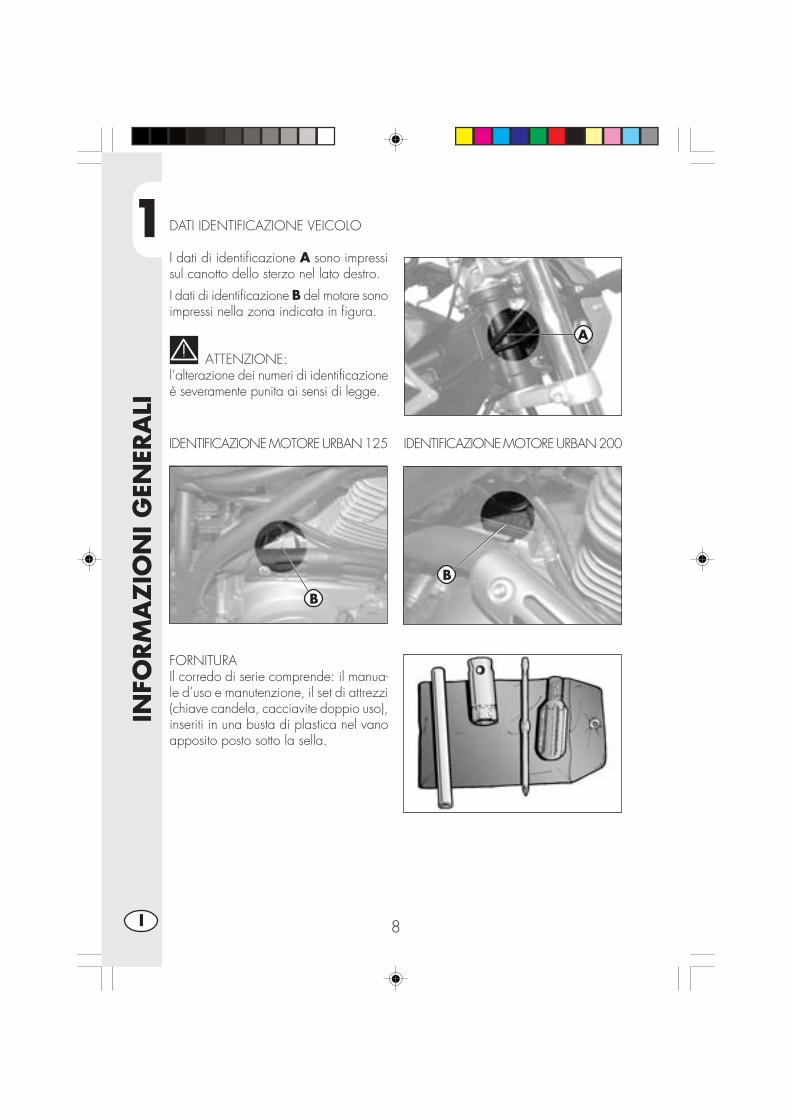
DATI IDENTIFICAZIONE VEICOLO
I dati di identificazione A sono impressisul canotto dello sterzo nel lato destro.
I dati di identificazione B del motore sonoimpressi nella zona indicata in figura.
ATTENZIONE:l’alterazione dei numeri di identificazioneè severamente punita ai sensi di legge.
IDENTIFICAZIONE MOTORE URBAN 125
FORNITURAIl corredo di serie comprende: il manua-le d’uso e manutenzione, il set di attrezzi(chiave candela, cacciavite doppio uso),inseriti in una busta di plastica nel vanoapposito posto sotto la sella.
A
IDENTIFICAZIONE MOTORE URBAN 200
B
B

1
INFO
RM
AZ
ION
I G
ENER
ALI
9 I
CARICO
•Carico massimo (conducente + passeggero): 280 Kg.•Non trasportare assolutamente oggetti voluminosi o troppo pesanti, che potrebbe-ro pregiudicare la stabilità del veicolo.
•Non trasportare oggetti che sporgano dal veicolo o che coprano i dispositivid’illuminazione e di segnalazione.
ATTENZIONE:• Per una guida sicura controllare frequentemente i pneumatici.•Mantenere la pressione dei pneumatici entro i limiti indicati.•Effettuare il controllo della pressione ogni 15 giorni.•Verificare la pressione solamente a pneumatici freddi.•Controllare prima di ogni viaggio che i pneumatici non presentino tagli, screpola-ture, abrasioni, rigonfiamenti, ecc... In questi casi far esaminare il pneumatico daun esperto in quanto potrebbero verificarsi condizioni estremamente pericolose.
• In caso di foratura arrestare subito il veicolo; proseguire la marcia, oltre ad essererischioso, può provocare irrimediabili danni al pneumatico ed al cerchio ruota.
• In condizioni di max. carico sono consigliate pressioni maggiori.•Lo spessore minimo del battistrada dei pneumatici (TUBE TYPE) non deve mai esse-re inferiore ai 2 mm. La mancata adempienza a questa norma è puni-ta ai sensi di legge.
PNEUMATICI
Pneumatico Anteriore Posteriore Dimensioni 80/100 - 19 49P 120/90-16 63P Pressione 1,4 ÷1,5 bar 1,5 ÷1,6 bar
Pressione troppo bassa Pressione troppo altaPressione giusta

1
INFO
RM
AZ
ION
I G
ENER
ALI
10I
CONOSCENZA DEL VEICOLO
1
2
34
5
7
8
9
19
20
13
14
10
15
16
12
17
11
11
18
21
22
24
25
24
17
6

1
INFO
RM
AZ
ION
I G
ENER
ALI
11 I
Elementi principali:
1 - Filtro aria2 - Serbatoio carburante3 - Tappo carburante4 - Silenziatore5 - Ammortizzatore posteriore6 - Faro anteriore7 - Indicatori di direzione anteriori8 - Fanale posteriore9 - Indicatori di direzione posteriori
10 - Cavalletto laterale11 - Specchi retrovisori12 - Pedane passeggero13 - Forcella14 - Pedane pilota15 - Sella16 - Motore17 - Parafango anteriore18 - Portatarga19 - Leva messa in moto20 - Serratura casco21 - Telaio22 - Catena23 - Paracatena24 - Pinza freno anteriore25 - Pinza freno posteriore

1
INFO
RM
AZ
ION
I G
ENER
ALI
12I
CHIAVI E SERRATUREIl veicolo viene fornito con due chiavientrambi, da utilizzare per il commutato-re/bloccasterzo e per la serratura casco.
ATTENZIONE:Non conservare la chiave di scorta al-l’interno del veicolo, ma in luogo sicuroed a portata di mano. Consigliamo diregistrare sul presente manuale (o altro-ve) il numero di codice impresso sullechiavi. In caso di smarrimento di entram-be si potranno richiedere dei duplicati.
ONOFF
LOCK
COMMUTATORE/BLOCCASTERZOControlla il circuito di accensione, l’inseri-mento del bloccasterzo e l’apertura sella.
OFF: Sistema elettrico disattivato.ON: Si può effettuare l’accensione del
veicolo.LOCK: Inserimento del bloccasterzo.
Per questa operazione occorresterzare il manubrio a sinistra,premere sulla chiave, ruotarlacompletamente in senso anti-orario e dopo rilasciarla.
SERRATURA CASCOInserire la chiave nella serratura posta sullato sinistro sotto la sella, e ruotarla insenso antiorario per aprire il gancioportacasco.

1
INFO
RM
AZ
ION
I G
ENER
ALI
13 I
1- LCD2- Commutatore a chiave3- Spia punto neutro4- Spia indicatori di direzione5- Spia abbaglianti6- Spia cavalletto7- Pulsante SCROLL8- Leva frizione9- Leva freno anteriore
10 - Manopola acceleratore11 - Pulsante accensione12 - Pulsante stop motore13 - Pulsante indicatori di direzione14 - Pulsante clacson15 - Deviatore luci16 - Passing17- Leva Starter (solo per URBAN125)
CRUSCOTTO E COMANDI
Nota: l’accensione della spia cavalletto indica la posizione abbassata del cavallet-to stesso. Per ragioni di sicurezza la moto si spegne all’inserimento della marcia.
2
14
10
11
8
1
9
6
3
5
4
7
12
13 15
16 17

1
INFO
RM
AZ
ION
I G
ENER
ALI
14I
ISTRUZIONI DI SETTAGGIO E FUNZIONAMENTO CONTACHILOMETRI
INDICE DEGLI ARGOMENTI
PARAGRAFO CONTENUTO
10.0 Test strumento e videata principale
10.1 Indicazione spie luminose
10.2 Velocità istantanea e percorrenza chilometrica totale (ODO)
20.0 Funzioni secondarie
20.1 Totalizzatore parziale (TRP)
20.2 Orologio (CLK)
20.3 Cronometro (LAP)
20.4 Velocità massima raggiunta (MAX)
30.0 Sostituzione della pila interna

1
INFO
RM
AZ
ION
I G
ENER
ALI
15 I
10.0 TEST STRUMENTO E VIDEATAPRINCIPALEAll’attivazione chiave o all’avviamentodel motore la strumentazione di bordoviene attivata presentando la videata dicontrollo in cui tutte le indicazioni e lespie sono attive per 3 secondi:
Pagina di controllo:Verifica globale di tutti i segmenti e ditutte le icone presenti su LCD e controllosugli indicatori luminosi.
Al termine della visualizzazione dellavideata di controllo viene automaticamen-te presentata la videata principale (Figu-ra 1) o l’ultima pagina selezionata pri-ma dello spegnimento precedente (vede-re par.20.0 e succ.).
Videata di controllo (check)
Figura 1

1
INFO
RM
AZ
ION
I G
ENER
ALI
16I
10.1 INDICAZIONE SPIE LUMINOSE EPULSANTE SCROLL
Lo strumento è dotato di 4 spie lumino-se con funzioni di segnalazione e diavviso:
•Spia Cavalletto rossa A: quandoattiva segnala che il cavalletto lateraledel veicolo è abbassato.
•Spia Neutral verde B: quando attivasegnala che il cambio è in posizionedi folle.
•Spia Abbagliante blu C: quandoattiva segnala che il faro abbaglianteè acceso.
•Spia Freccie verde D: quando attivasegnala che gli indicatori di direzione(destri o sinistri) sono attivati
•Pulsante Scroll E, permette di muover-si all’interno dello strumento selezio-nando la funzione desiderata (Vediparagrafo 20.0 e successivi)
A
B
C
DE
1
INFO
RM
AZ
ION
I G
ENER
ALI
17 I
Figura 1
Figura 1A
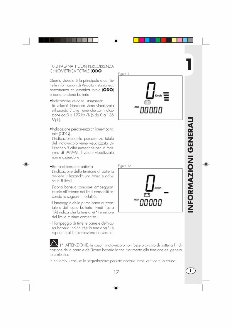
10.2 PAGINA 1 CON PERCORRENZACHILOMETRICA TOTALE (ODO)
Questa videata è la principale e contie-ne le informazioni di Velocità instantanea,percorrenza chilometrica totale (ODO)e barra tensione batteria:
•Indicazione velocità istantanea:La velocità istantanea viene visualizzatautilizzando 3 cifre numeriche con indica-zione da 0 a 199 km/h (o da 0 a 136Mph).
•Indicazione percorrenza chilometrica to-tale (ODO).L’indicazione della percorrenza totaledel motoveicolo viene visualizzata uti-lizzando 5 cifre numeriche per un mas-simo di 99999. Il valore visualizzatonon è azzerabile.
•Barra di tensione batteriaL’indicazione della tensione di batteriaavviene utilizzando una barra suddivi-sa in 8 livelli.
L’icona batteria compare lampeggian-te solo all’esterno dei limiti consentiti se-condo le seguenti modalità:
- Il lampeggio della prima barra orizzon-tale e dell’icona batteria (vedi figura1A) indica che la tensione(*) è minoredel limite minimo consentito.
- Il lampeggio di tutte le barre e dell’ico-na batteria indica che la tensione(*) èsuperiore al limite massimo consentito.
(*) ATTENZIONE: In caso il motoveicolo non fosse provvisto di batteria l’indi-cazione della barra e dell’icona batteria fanno riferimento alla tensione del genera-tore elettrico!
In entrambi i casi se la segnalazione persiste occorre farne verificare la causa!

1
INFO
RM
AZ
ION
I G
ENER
ALI
18I
20.0 FUNZIONI SECONDARIE
Dalla videata principale è possibile accedere in sequenza alle successive funzionisecondarie che consentono la visualizzazione di informazioni secondo la seguentelista:
Totalizzatore parziale (TRP)
Orologio (CLK)
Cronometro (LAP)
Velocità massima (MAX)
In ogni caso oltre all’informazione relativa alla specifica videata, continueranno adessere presenti sullo schermo l’indicazione di velocità istantanea e la barra/iconatensione batteria.
Tutte le videate a partire dalla principale (ODO) sono raggiungibili solo nella lorosequenza tramite l’azionamento breve del pulsante SCROLL. Questo significa chel’ordine di visualizzazione sarà il seguente:
ODO -> TRP -> CLK -> LAP -> MAX
Naturalmente premendo il pulsante SCROLL quando la videata di Velocità massi-ma è presente (MAX) si passerà nuovamente alla pagina principale (ODO) e lasequenza potrà riprendere a piacimento.
ATTENZIONE:L’UTILIZZO DEL PULSANTE SCROLL NON E’ CONSENTITO DURANTE LA MAR-CIA DEL VEICOLO E CIOE’ QUANDO L’INDICAZIONE DELLA VELOCITA’ ISTAN-TANEA E’ DIVERSA DA 0 Km/h-Mph.
QUESTO PER GARANTIRE LA NECESSARIA SICUREZZA DURANTE LACONDUZIONE DEL MOTOVEICOLO.
1
INFO
RM
AZ
ION
I G
ENER
ALI
19 I
Figura 2
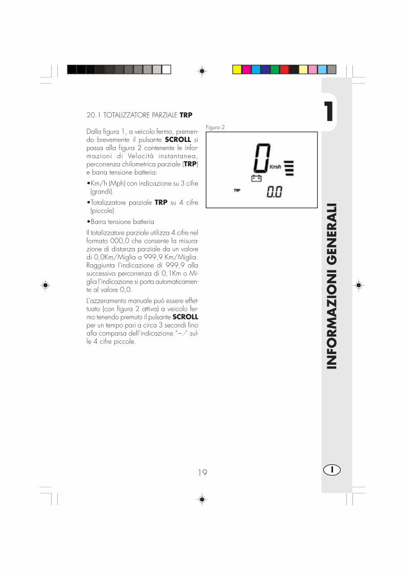
20.1 TOTALIZZATORE PARZIALE TRP
Dalla figura 1, a veicolo fermo, premen-do brevemente il pulsante SCROLL sipassa alla figura 2 contenente le infor-mazioni di Velocità instantanea,percorrenza chilometrica parziale (TRP)e barra tensione batteria:
•Km/h (Mph) con indicazione su 3 cifre(grandi).
•Totalizzatore parziale TRP su 4 cifre(piccole)
•Barra tensione batteria
Il totalizzatore parziale utilizza 4 cifre nelformato 000,0 che consente la misura-zione di distanza parziale da un valoredi 0,0Km/Miglia a 999,9 Km/Miglia.Raggiunta l’indicazione di 999,9 allasuccessiva percorrenza di 0,1Km o Mi-glia l’indicazione si porta automaticamen-te al valore 0,0.
L’azzeramento manuale può essere effet-tuato (con figura 2 attiva) a veicolo fer-mo tenendo premuto il pulsante SCROLLper un tempo pari a circa 3 secondi finoalla comparsa dell’indicazione “---.-“ sul-le 4 cifre piccole.

1
INFO
RM
AZ
ION
I G
ENER
ALI
20I
Figura 3
20.2 OROLOGIO CLK
Dalla figura 2, a veicolo fermo, premen-do brevemente il pulsante SCROLL sipassa alla figura 3 contenente le infor-mazioni di Velocità instantanea, orologio24h e barra tensione batteria:
•Km/h con indicazione su 3 cifre (grandi).
•Orologio hh:mm su 4 cifre (piccole)
•Barra tensione batteria
L’orologio indica l’orario su un arco di24 ore (da 0h:00’ a 23h:59’) e la suaregolazione è consentita solo a veicolofermo attraverso la seguente procedura:
•Premere il pulsante SCROLL fino allampeggio dei numeri relativi alle ore.
•Rilasciando e ripremendo il pulsanteSCROLL le ore avanzano di un nume-ro. Mantenendolo premuto avanzanoautomaticamente. Lasciandolo inattivosi passa al punto 4.
•Rilasciare il pulsante SCROLL quandosi è terminata l’impostazione delle ore:dopo 2 secondi lampeggieranno le ci-fre dei minuti.
•Operare come al punto 2 perl’impostazione dei minuti. Lasciandoinattivo il pulsante SCROLL per 2 se-condi anche i minuti verranno memoriz-zati e si uscirà dalla modalità diregolazione orologio.
1
INFO
RM
AZ
ION
I G
ENER
ALI
21 I
Figura 4
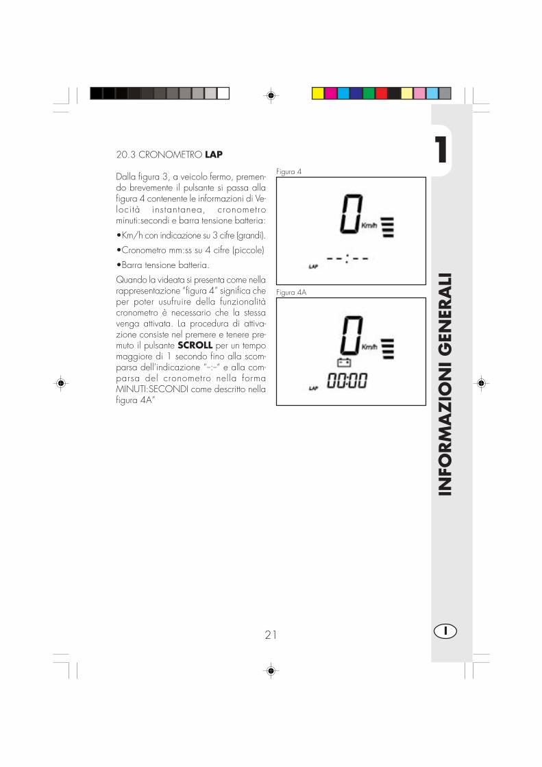
20.3 CRONOMETRO LAP
Dalla figura 3, a veicolo fermo, premen-do brevemente il pulsante si passa allafigura 4 contenente le informazioni di Ve-locità instantanea, cronometrominuti:secondi e barra tensione batteria:
•Km/h con indicazione su 3 cifre (grandi).
•Cronometro mm:ss su 4 cifre (piccole)
•Barra tensione batteria.
Quando la videata si presenta come nellarappresentazione “figura 4” significa cheper poter usufruire della funzionalitàcronometro è necessario che la stessavenga attivata. La procedura di attiva-zione consiste nel premere e tenere pre-muto il pulsante SCROLL per un tempomaggiore di 1 secondo fino alla scom-parsa dell’indicazione “--:--“ e alla com-parsa del cronometro nella formaMINUTI:SECONDI come descritto nellafigura 4A”
Figura 4A
1
INFO
RM
AZ
ION
I G
ENER
ALI
22I
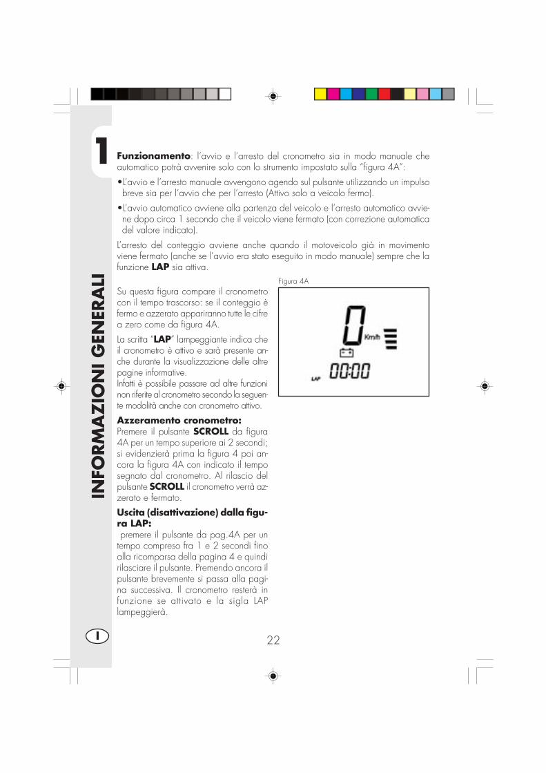
Funzionamento: l’avvio e l’arresto del cronometro sia in modo manuale cheautomatico potrà avvenire solo con lo strumento impostato sulla “figura 4A”:
•L’avvio e l’arresto manuale avvengono agendo sul pulsante utilizzando un impulsobreve sia per l’avvio che per l’arresto (Attivo solo a veicolo fermo).
•L’avvio automatico avviene alla partenza del veicolo e l’arresto automatico avvie-ne dopo circa 1 secondo che il veicolo viene fermato (con correzione automaticadel valore indicato).
L’arresto del conteggio avviene anche quando il motoveicolo già in movimentoviene fermato (anche se l’avvio era stato eseguito in modo manuale) sempre che lafunzione LAP sia attiva.
Figura 4ASu questa figura compare il cronometrocon il tempo trascorso: se il conteggio èfermo e azzerato appariranno tutte le cifrea zero come da figura 4A.
La scritta “LAP” lampeggiante indica cheil cronometro è attivo e sarà presente an-che durante la visualizzazione delle altrepagine informative.Infatti è possibile passare ad altre funzioninon riferite al cronometro secondo la seguen-te modalità anche con cronometro attivo.
Azzeramento cronometro:Premere il pulsante SCROLL da figura4A per un tempo superiore ai 2 secondi;si evidenzierà prima la figura 4 poi an-cora la figura 4A con indicato il temposegnato dal cronometro. Al rilascio delpulsante SCROLL il cronometro verrà az-zerato e fermato.
Uscita (disattivazione) dalla figu-ra LAP: premere il pulsante da pag.4A per untempo compreso fra 1 e 2 secondi finoalla ricomparsa della pagina 4 e quindirilasciare il pulsante. Premendo ancora ilpulsante brevemente si passa alla pagi-na successiva. Il cronometro resterà infunzione se attivato e la sigla LAPlampeggierà.

1
INFO
RM
AZ
ION
I G
ENER
ALI
23 I
Figura 5
20.4 VELOCITA’ MASSIMA RAGGIUN-TA MAX
Dalla figura 4, a veicolo fermo, premendobrevemente il pulsante SCROLL si passaalla figura 5 contenente le informazioni diVelocità instantanea, velocità massima rag-giunta e barra tensione batteria:
•Km/h con indicazione su 3 cifre (grandi).
•Velocità massima raggiunta su 3 cifre(piccole)
•Barra tensione batteria.
L’indicazione “Km/h” o “Mph” è lampeg-giante in questa videata.
Durante la marcia del veicolo l’indica-zione di velocità massima raggiunta vie-ne costantemente aggiornata e indicatasulle 3 cifre piccole. Questo valore vie-ne in ogni caso memorizzato anche sela figura 5 non è attiva.
L’azzeramento dell’indicazione può es-sere effettuato (con figura 5 attiva) a vei-colo fermo tenendo premuto il pulsanteSCROLL per un tempo pari a circa 3secondi fino alla comparsa dell’indica-zione “---“ sulle 3 cifre piccole.
Per tornare alla figura 1 iniziale è neces-sario azionare brevemente il pulsanteSCROLL.
30.0 LUNGA INATTIVITÀ
Lo strumento digitale è alimentato dallabatteria del veicolo, in caso di lunga inat-tività è buona norma scollegare labattertia.Tale operazione però comporta la perdi-ta delle impostazioni dell’ora e della ve-locità massima raggiunta.

1
INFO
RM
AZ
ION
I G
ENER
ALI
24I
DATI TECNICI
CARICO MASSIMOconducente + passeggero ............................................................. 280 (kg)
PESO VEICOLOin ordine di marcia (a secco) URBAN200 ........................................ 103 (kg)in ordine di marcia (a secco) URBAN125 ........................................ 101 (Kg)
DIMENSIONIlunghezza totale ........................................................................ 2143 mmlarghezza totale ........................................................................... 820 mmaltezza totale ............................................................................ 1170 mminterasse ................................................................................... 1372 mmaltezza sella ................................................................................ 836 mmluce a terra ................................................................................. 288 mm
TELAIO........................................................ in acciaio a doppia culla chiusa
CAPACITÀ DI RIEMPIMENTOserbatoio carburante ......................................................................... 6 (litri)di cui lt di riserva ..........................................................................1.5 (litri)consumo medio ........................................................................ 25 Km/litri

1
INFO
RM
AZ
ION
I G
ENER
ALI
25 I
SOSPENSIONE ANTERIOREforcella idraulica con steli di Ø 37 mm.Quantità olio per stelo:destro .................................................................................... 310 ± 5 ccsinistro ................................................................................... 310 ± 5 ccTipo olio ............................................................................. SHELL EBH 16Livello olio ........................................... 142 mm dal bordo superiore del tubo
con forcella a fine corsa e senza mollaavancorsa ................................................................................. 82,5 mm
SOSPENSIONE POSTERIOREmonoammortizzatore idraulico progressivo e regolazione in estensione e precaricomollacorsa ammortizzatore ..................................................................... 63 mm
FRENO ANTERIOREa disco Ø 245 mm con comando idraulico
FRENO POSTERIOREa disco Ø 220 mm con comando idraulico
1
INFO
RM
AZ
ION
I G
ENER
ALI
26I
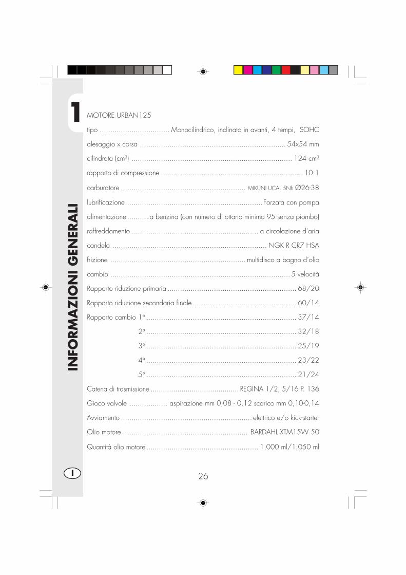
MOTORE URBAN125
tipo ................................. Monocilindrico, inclinato in avanti, 4 tempi, SOHC
alesaggio x corsa ..................................................................... 54x54 mm
cilindrata (cm3) ............................................................................ 124 cm3
rapporto di compressione ................................................................... 10:1
carburatore ........................................................... MIKUNI UCAL 5Nh Ø26-38
lubrificazione ................................................................ Forzata con pompa
alimentazione .......... a benzina (con numero di ottano minimo 95 senza piombo)
raffreddamento ............................................................ a circolazione d’aria
candela ......................................................................... NGK R CR7 HSA
frizione ................................................................ multidisco a bagno d’olio
cambio ..................................................................................... 5 velocità
Rapporto riduzione primaria ............................................................. 68/20
Rapporto riduzione secondaria finale ................................................. 60/14
Rapporto cambio 1° ....................................................................... 37/14
2° ....................................................................... 32/18
3° ....................................................................... 25/19
4° ....................................................................... 23/22
5° ....................................................................... 21/24
Catena di trasmissione ........................................... REGINA 1/2, 5/16 P. 136
Gioco valvole .................. aspirazione mm 0,08 - 0,12 scarico mm 0,10-0,14
Avviamento .............................................................. elettrico e/o kick-starter
Olio motore ........................................................... BARDAHL XTM15W 50
Quantità olio motore ..................................................... 1,000 ml/1,050 ml

1
INFO
RM
AZ
ION
I G
ENER
ALI
27 I
MOTORE URBAN200
tipo ......................................... Monocilindrico a quattro tempi SUZUKI H402
alesaggio x corsa .................................................................. 66x58,2 mm
cilindrata (cm3) ............................................................................ 199 cm3
rapporto di compressione .................................................................. 9,4:1
carburatore ............................................................... MIKUNI BST31 42AD
lubrificazione .................................................................. con olio in coppa
alimentazione .............................................. a benzina (con numero di ottanominimo 95 senza piombo) mediante carburatore
raffreddamento ............................................................ a circolazione d’aria
candela .............................................................................. NGK DR8 EA
frizione ................................................................ multidisco a bagno d’olio
cambio ..................................................................................... 5 velocità
Rapporto riduzione primaria ................................................. 3,157 (60/19)
Rapporto riduzione finale..................................................... 3,200 (48/15)
Rapporto cambio 1° ........................................................... 3,000 (33/11)
2° ........................................................... 1,933 (29/15)
3° ........................................................... 1,437 (23/16)
4° ........................................................... 1,095 (23/21)
5° ........................................................... 0,913 (21/23)
Catena di trasmissione .......................................... REGINA 5/8, 1/4 P 104
Gioco valvole ..................................... aspirazione e scarico mm 0,08 - 0,13
Avviamento .............................................................. elettrico e/o kick-starter
Olio motore ........................................................... BARDAHL XTM15W 50
Quantità olio motore .................... cambio olio 850 ml con cambio filtro 950 mlrevisione 1300 ml

1
INFO
RM
AZ
ION
I G
ENER
ALI
28I
SCHEMA ELETTRICO URBAN 125
1
INFO
RM
AZ
ION
I G
ENER
ALI
29 I
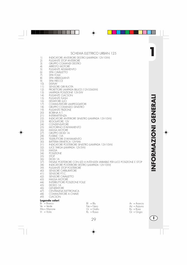
SCHEMA ELETTRICO URBAN 1251) INDICATORE ANTERIORE DESTRO (LAMPADA 12V-10W)2) PULSANTE STOP ANTERIORE3) GRUPPO COMANDI DESTRO4) ARRESTO MOTORE5) PULSANTE AVVIAMENTO6) SPIA CAVALLETTO7) SPIA FOLLE8) SPIA ABBAGLIANTI9) SPIA FRECCE10) DISPLAY11) SENSORE GIRI RUOTA12) PROIETTORE LAMPADA BILUCE (12V-5560W)13) LAMPADA POSIZIONE 12V-5W14) PULSANTE CLACSON15) PULSANTE FLASH16) DEVIATORE LUCI17) COMMUTATORE LAMPEGGIATORI18) GRUPPO COMANDO SINISTRO19) PULSANTE FRIZIONE20) BOBINA A.T.21) INTERMITTENZA22) INDICATORE ANTERIORE SINISTRO (LAMPADA 12V-10W)23) REGOLATORE 12V24) CONDENSATORE25) MOTORINO D’AVVIAMENTO26) MASSA MOTORE27) GRUPPO DIODI 1A28) FUSIBILE 15A29) TELERUTTORE D’AVVIAMENTO30) BATTERIA ERMETICA 12V-9Ah31) INDICATORE POSTERIORE SINISTRO (LAMPADA 12V-10W)32) LUCE TARGA (LAMPADA 12V-5W)33) MASSA34) POSIZIONE35) STOP36) DIODI 1A37) FANALE PODTERIORE CON LED A INTENSITA VARIABILE PER LUCE POSIZIONE E STOP38) INDICATORE POSTERIORE DESTRO (LAMPADA 12V-10W)39) PULSANTE STOP POSTERIORE40) SENSORE CARBURATORE41) SENSORE P.T.C.42) SENSORE CAVALLETTO43) MASSA MOTORE44) INTERRUTTORE POSIZIONE FOLLE45) DIODO 1A46) GENERATORE47) CENTRALINA ELETTRONICA48) COMMUTATORE A CHIAVE49) CLACSONLegenda coloriBi = BiancoVe = VerdeMa= MarroneVi = Viola
Bl = BluNe = NeroGi = GialloRs = Rosso
Ar = ArancioAz = AzzurroRo = RosaGr = Grigio

1
INFO
RM
AZ
ION
I G
ENER
ALI
30I
SCHEMA ELETTRICO URBAN 200

1
INFO
RM
AZ
ION
I G
ENER
ALI
31 I
Legenda coloriBi = BiancoVe = VerdeMa= MarroneVi = Viola
Bl = BluNe = NeroGi = GialloRs = Rosso
Ar = ArancioAz = AzzurroRo = RosaGr = Grigio
SCHEMA ELETTRICO URBAN 1251) INDICATORE ANTERIORE DESTRO (LAMPADA 12V-10W)2) PULSANTE STOP ANTERIORE3) GRUPPO COMANDI DESTRO4) ARRESTO MOTORE5) PULSANTE AVVIAMENTO6) SPIA CAVALLETTO7) SPIA FOLLE8) SPIA ABBAGLIANTI9) SPIA FRECCE10) DISPLAY11) SENSORE GIRI RUOTA12) PROIETTORE ANTERIORE LAMPADA BILUCE (12V-5560W)13) LAMPADA POSIZIONE (12V-5W)14) PULSANTE CLACSON15) PULSANTE FLASH16) DEVIATORE LUCI17) COMMUTATORE LAMPEGGIATORI18) GRUPPO COMANDO SINISTRO19) PULSANTE FRIZIONE20) INDICATORE ANTERIORE SINISTRO (LAMPADA 12V-10W)21) INTERMITTENZA22) BOBINA A.T.23) REGOLATORE 12V24) GRUPPO DIODI 1A25) FUSIBILE 15A26) MASSA MOTORE27) MOTORINO D’AVVIAMENTO28) CONDENSATORE 4700μ F-25V29) DIODO 6A30) TELERUTTORE D’AVVIAMENTO31) BATTERIA ERMETICA32) INDICATORE POSTERIORE SINISTRO (LAMPADA 12V-10W)33) LUCE TARGA (LAMPADA 12V-5W)34) MASSA35) POSIZIONE36) STOP37) Nº2 DIODI 1A38) FANALE PODTERIORE CON LED A INTENSITA VARIABILE PER LUCE POSIZIONE E STOP39) INDICATORE POSTERIORE DESTRO (LAMPADA 12V-10W40) PILSANTE STOP41) SENSORE CARBURANTE42) SENSORE P.T.C43) SENSORE CAVALLETTO44) MASSA MOTORE45) INTERRUTTORE POSIZIONE FOLLE46) GENERATORE47) CENTRALINA ELETTRONICA48) COMMUTATORE A CHIAVE49) CLACSON

1
INFO
RM
AZ
ION
I G
ENER
ALI
32I
DISPOSITIVI ELETTRICI
BATTERIASi accede alla batteria A rimuovendo lasella, come descritto nella sezione “Rimo-zione delle carrozzeria” a pagina 52.
Rimuovere il coperchio B svitando la viteC, sganciare l’elastico D scollegare i cavie rimuovere la batteria.
ATTENZIONE:Per evitare danni all’impianto elettrico,non scollegare mai i cavi con il motorein moto.
Reinserire la batteria A nell’apposita sedefissandola con l’elastico D.Collegare il terminale dei cavi di colorenero al negativo (-) e i due cavi di colorerosso al positivo (+) dopodiche inserirela relativa protezione.
CENTRALINALa centralina E si trova sul lato sinistrodel veicolo, per accedere a questo di-spositivo è necessario rimuovere lafiancatina sinistra sotto al serbatoio comedescritto a pagina 53
AVVISATORE ACUSTICOIn posizione anteriore, sul lato sinistro delmotoveicolo si trova l’avvisatore acusti-co F.
AD
E
F
B C

1
INFO
RM
AZ
ION
I G
ENER
ALI
33 I
INTERMITTENZAL’intermittenza G si trova sotto il serbato-io ed è raggiungibile rimuovendo lafiancatina destra sotto al serbatoio comedescritto a pagina 53.
BOBINA A.T. - RELE AVVIAMENTO - RELECAVALLETTO - FUSIBILEIn posizione centrale, sul lato sinistro delveicolo si trovano: la bobina H, il relèd’avviamento I, il relè cavalletto L e ilfusibile M.Questultimo protegge le seguenti utenze:- Clacson,- Lampeggiatori,- Strumentazione,- Accensione motore
Note:Un fusibile bruciato deve essre sostituitoesclusivamente con un altro equivalente.Se anche il nuovo fusibile dovesse bru-ciarsi una volta montato, è consigliabilerivolgersi ad una officina autorizzataBETAMOTOR.Il fusibile ha una capacita di 15 Ampere.
ATTENZIONE:Non montare in nessun caso un fusibilecon maggiore potenza o tentare di “ag-giustare” lo stesso fusibile. Interventi nonappropriati potrebbero causare il gua-sto dell’intero impianto elettrico.
REGOLATORE DI TENSIONEIn posizione centrale è collocato ilregolatore di tensione N.
G
H
L
N
I
M

1
INFO
RM
AZ
ION
I G
ENER
ALI
34I
A
VALVOLA AISSi chiama AIS ed è un sistema d’immis-sione d’aria che consente di completarela combustione di quella parte diidrocarburi incombusti, residuo del ciclotermodinamico.
Per accedere alla valvola A è necessa-rio rimuovere la protezione destra sotto ilserbatoio come descritto a pagina 52

2
UTI
LIZ
ZO
DEL
VEI
CO
LO
35 I
INDICE ARGOMENTI
CAP. 2 UTILIZZO DEL VEICOLO
Controlli e manutenzione prima e dopo l’utilizzo in fuoristrada
Lubrificanti e liquidi consigliati
Rodaggio
Avviamento del motore
Arresto del motore
Rifornimento carburante
2
UTI
LIZ
ZO
DEL
VEI
CO
LO
36I
CONTROLLI E MANUTENZIONE PRIMA E DOPOL’UTILIZZO IN FUORISTRADA
Onde evitare spiacevoli inconvenienti durante il funzionamento del veicolo èconsigliabile effettuare, sia prima che dopo l’utilizzo, alcune operazioni di controlloe manutenzione. Infatti pochi minuti dedicati a queste operazioni, oltre a rendere laguida più sicura, possono farvi risparmiare tempo e denaro. Quindi procederecome segue:
PNEUMATICI verificare la pressione, lo stato generale e lo spessore del batti-strada (vedi pagina 9)
RAGGI verificare la corretta tensioneBULLONERIA risentire completamente tutta la bulloneriaCATENA verificare la tensione (gioco 20 mm) e se necessario ingrassareFILTRO ARIA pulire il filtro e bagnarlo con olio (vedi pag.48)
Nota:Controllare la presenza dei documenti di identificazione del veicolo.Nei giorni freddi è consigliabile prima della partenza, fare scaldare il motore facen-dolo funzionare al minimo per alcuni istanti.Ogni volta che il veicolo viene utilizzato in fuoristrada occorre lavarlo accuratamente.

2
UTI
LIZ
ZO
DEL
VEI
CO
LO
37 I
LUBRIFICANTI E LIQUIDI CONSIGLIATI
Per un migliore funzionamento ed una più lunga durata del mezzo si raccomanda diutilizzare preferibilmente i prodotti elencati in tabella:
TIPO DI PRODOTTO SPECIFICHE TECNICHE
OLIO MOTORE BARDAHL XTM 15W 50
OLIO FRENI BARDAHL BRAKE FLUID DOT4
OLIO PER FORCELLE SHELL EBH 16
GRASSO PER TIRANTERIE BARDAHL Outboard Grease NLGI2
Nota:Per gli interventi di sostituzione si raccomanda di attenersi scrupolosamente allatabella di manutenzione programmata a pagina 57.
RODAGGIO
Il rodaggio ha una durata di circa 10 ore di attività, durante questo periodo siconsiglia di:•Utilizzare il veicolo dopo aver fatto scaldare bene il motore•Evitare di viaggiare a velocità costante (variando la velocità i vari componenti siassesteranno uniformemente ed in minor tempo.
•Evitare di ruotare la manopola dell’acceleratore per più di 3/4
ATTENZIONE:•Dopo i primi 1000 Km di percorrenza sostituire l’olio del motore•Utilizzare sempre benzina super senza piombo•Dopo la prima uscita fuoristrada provvedere a controllare tutta la bulloneria.

2
UTI
LIZ
ZO
DEL
VEI
CO
LO
38I
AVVIAMENTO DEL MOTORE
•Posizionare il rubinetto del serbatoiocarburante in posizione APERTO (vedidisegno accanto).
•Ruotare la chiave nel commutatore insenso orario ed assicurarsi che la spiadel folle, posta sul cruscotto, sia acce-sa (vedi richiamo 3 a pagina 13).
•Assicurarsi che l’interruttore di emergen-za A, posto sul comando gas, sia inposizione ON.
Importante:A motore freddo utilizzare sempre lostarter D.
Avviamento elettricoTirare la leva frizione e contemporaneamentespingere il pulsante avviamento B sul co-mando gas senza ruotare la manopola gas.
Kick-starterIntervenire sulla leva messa in moto C,affondando con il piede un colpo deci-so quindi ripiegare la leva.
Nota:E’ possibile avviare il motore anche conil cavalletto abbassato e la spia rossasul cruscotto accesa, purchè il pedale diinserimento delle marce sia in posizionefolle, segnalato dalla spia verde sullastrumentazione.Per ragioni di sicurezza, l’eventuale in-serimento della marcia; anche con frizio-ne attivata comporta lo spengimento delmotore.Quindi è necessario chiudere il cavalletto epoi procedere all’inserimento della marcia.
Nota:In caso di emergenza, questo veicolo puòfunzionare anche senza l’uso della batteria.
A
ON OFF
B
C
Aperto Chiuso Riserva
2
UTI
LIZ
ZO
DEL
VEI
CO
LO
39 I
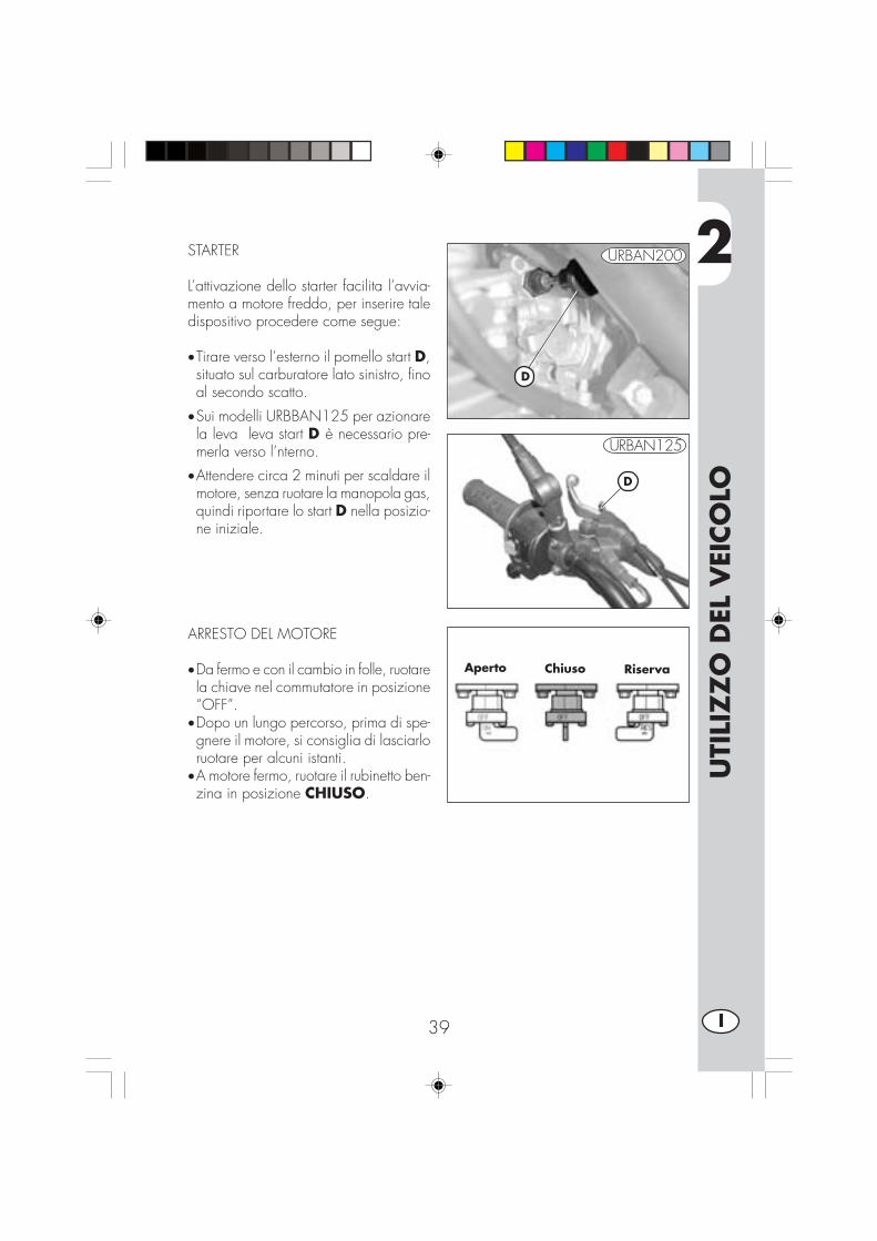
ARRESTO DEL MOTORE
•Da fermo e con il cambio in folle, ruotarela chiave nel commutatore in posizione“OFF”.
•Dopo un lungo percorso, prima di spe-gnere il motore, si consiglia di lasciarloruotare per alcuni istanti.
•A motore fermo, ruotare il rubinetto ben-zina in posizione CHIUSO.
Aperto Chiuso Riserva
STARTER
L’attivazione dello starter facilita l’avvia-mento a motore freddo, per inserire taledispositivo procedere come segue:
•Tirare verso l’esterno il pomello start D,situato sul carburatore lato sinistro, finoal secondo scatto.
•Sui modelli URBBAN125 per azionarela leva leva start D è necessario pre-merla verso l’nterno.
•Attendere circa 2 minuti per scaldare ilmotore, senza ruotare la manopola gas,quindi riportare lo start D nella posizio-ne iniziale.
D
D
URBAN125
URBAN200

2
UTI
LIZ
ZO
DEL
VEI
CO
LO
40I
RIFORNIMENTO CARBURANTE
•Spegnere il motore.
•Rimuovere il tappo A.
Nota:La capacità del serbatoio è di circa 6litri di cui 1 di riserva.
ATTENZIONE:La benzina è estremamente infiammabile.
Eventuali trabocchi di benzina sulla car-rozzeria o su altre parti, devono essereprontamente rimossi.
Prima di effettuare il rifornimento benzi-na, spegnere il motore.
Evitare di far cadere la benzina dal ser-batoio durante il rifornimento.
Non avvicinarsi al bocchettone del ser-batoio con fiamme libere o sigarette ac-cese.
Evitare anche di inalare vapori nocivi.
A
3
CO
NTR
OLL
I E
MA
NU
TEN
ZIO
NE
41 I
INDICE ARGOMENTI
CAP. 3 CONTROLLI E MANUTENZIONE
Olio motore e filtro olio
Tubo raccolta fumi
Olio pompa freni, spurgo freni
Olio forcelle
Filtro aria
Candela
Freni: anteriore, posteriore
Batteria
Rimozione carrozzeria
Pulizia del veicolo e controlli
Manutenzione programmata
Lunga inattività del veicolo
3
CO
NTR
OLL
I E
MA
NU
TEN
ZIO
NE
42I
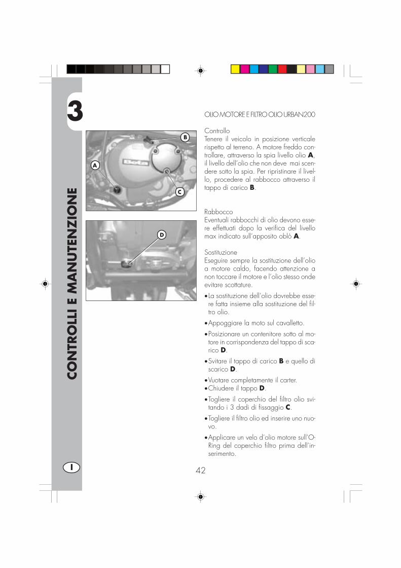
OLIO MOTORE E FILTRO OLIO URBAN200
ControlloTenere il veicolo in posizione verticalerispetto al terreno. A motore freddo con-trollare, attraverso la spia livello olio A,il livello dell’olio che non deve mai scen-dere sotto la spia. Per ripristinare il livel-lo, procedere al rabbocco attraverso iltappo di carico B.
RabboccoEventuali rabbocchi di olio devono esse-re effettuati dopo la verifica del livellomax indicato sull’apposito oblò A.
SostituzioneEseguire sempre la sostituzione dell’olioa motore caldo, facendo attenzione anon toccare il motore e l’olio stesso ondeevitare scottature.
• La sostituzione dell’olio dovrebbe esse-re fatta insieme alla sostituzione del fil-tro olio.
•Appoggiare la moto sul cavalletto.
•Posizionare un contenitore sotto al mo-tore in corrispondenza del tappo di sca-rico D.
•Svitare il tappo di carico B e quello discarico D.
•Vuotare completamente il carter.•Chiudere il tappo D.
•Togliere il coperchio del filtro olio svi-tando i 3 dadi di fissaggio C.
•Togliere il filtro olio ed inserire uno nuo-vo.
•Applicare un velo d’olio motore sull’O-Ring del coperchio filtro prima dell’in-serimento.
B
A
C
D
3
CO
NTR
OLL
I E
MA
NU
TEN
ZIO
NE
43 I
• Inserire il coperchio filtro olio, dopo avermontato molla ed O-Ring e serrare i tredadi di fissaggio C.
• Introdurre la giusta quantità di olio:- cambio olio ........................ 850 ml- con cambio filtro ................. 950 ml- revisione .......................... 1300 ml
•Richiudere il tappo di carico B.
•Avviare il motore lasciandolo girare perqualche minuto prima di spegnerlo
•Spegnere il motore ed attendere circa unminuto, quindi controllare il livello ed even-tualmente rabboccare, senza mai supera-re il livello max indicato sull’oblò A.
Nota:superati i primi 1000 km di percorrenzasostituire l’olio motore. Le successive sostitu-zioni devono essere effettuate ogni 5000km o 15 mesi (vedere tabella pag. 57),utilizzando i lubrificanti consigliati a pag. 37.Per il filtro olio, invece, la prima sostituzio-ne deve essere effettuata insieme all’oliomotore; le successive ogni 10.000 km (30mesi).
AVVERTENZA:Smaltire l’olio usato nel rispetto delle norma-tive vigenti.
3
CO
NTR
OLL
I E
MA
NU
TEN
ZIO
NE
44I
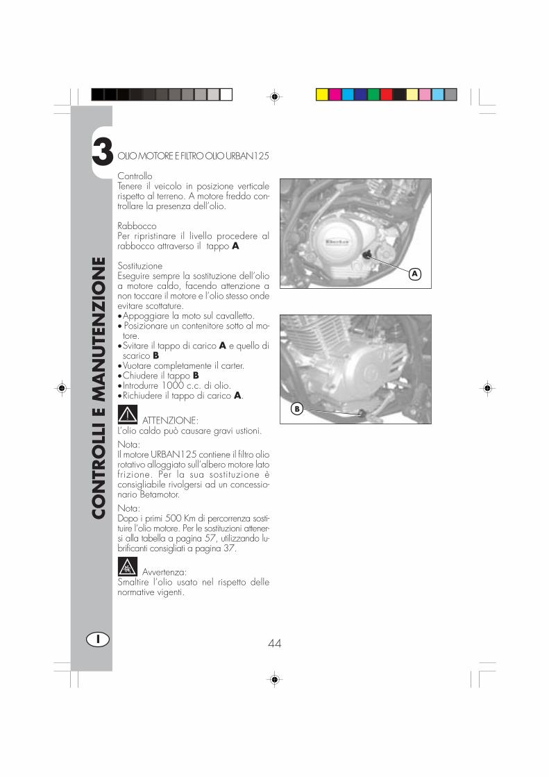
OLIO MOTORE E FILTRO OLIO URBAN125
ControlloTenere il veicolo in posizione verticalerispetto al terreno. A motore freddo con-trollare la presenza dell’olio.
RabboccoPer ripristinare il livello procedere alrabbocco attraverso il tappo A
SostituzioneEseguire sempre la sostituzione dell’olioa motore caldo, facendo attenzione anon toccare il motore e l’olio stesso ondeevitare scottature.•Appoggiare la moto sul cavalletto.• Posizionare un contenitore sotto al mo-tore.
•Svitare il tappo di carico A e quello discarico B
•Vuotare completamente il carter.•Chiudere il tappo B• Introdurre 1000 c.c. di olio.•Richiudere il tappo di carico A.
ATTENZIONE:L’olio caldo può causare gravi ustioni.Nota:Il motore URBAN125 contiene il filtro oliorotativo alloggiato sull’albero motore latofrizione. Per la sua sostituzione èconsigliabile rivolgersi ad un concessio-nario Betamotor.Nota:Dopo i primi 500 Km di percorrenza sosti-tuire l’olio motore. Per le sostituzioni attener-si alla tabella a pagina 57, utilizzando lu-brificanti consigliati a pagina 37.
Avvertenza:Smaltire l’olio usato nel rispetto dellenormative vigenti.
A
B
3
CO
NTR
OLL
I E
MA
NU
TEN
ZIO
NE
45 I
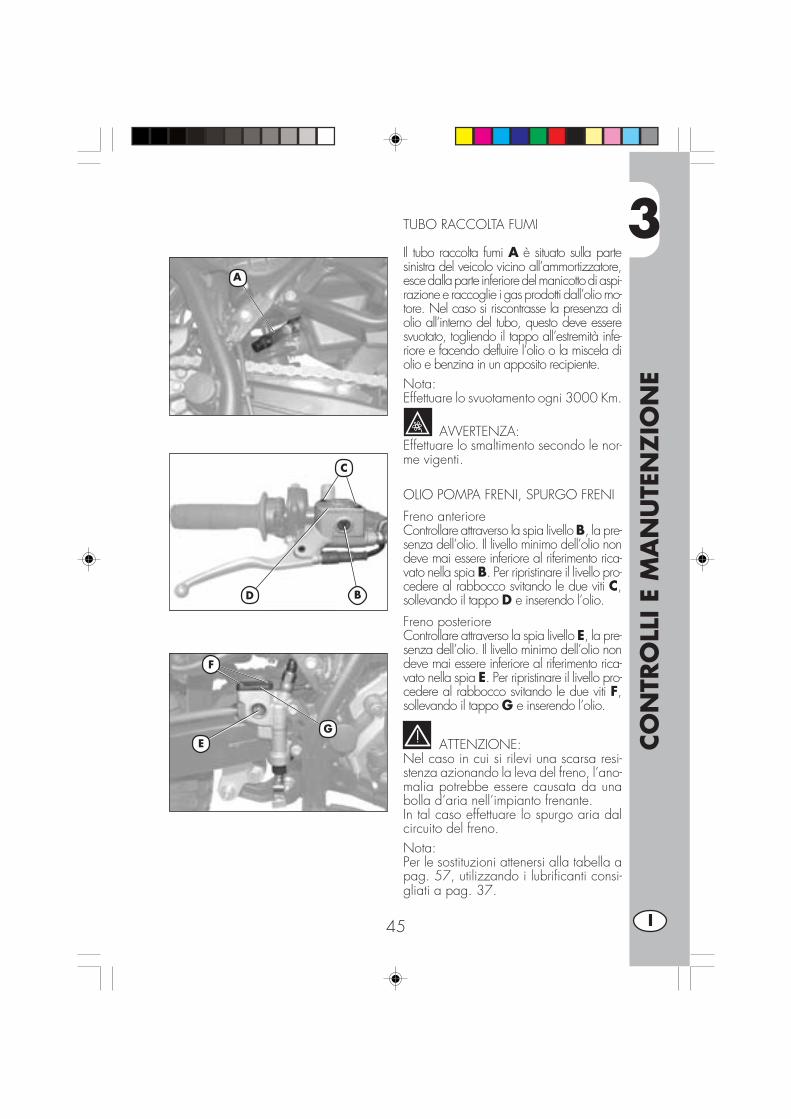
TUBO RACCOLTA FUMI
Il tubo raccolta fumi A è situato sulla partesinistra del veicolo vicino all’ammortizzatore,esce dalla parte inferiore del manicotto di aspi-razione e raccoglie i gas prodotti dall’olio mo-tore. Nel caso si riscontrasse la presenza diolio all’interno del tubo, questo deve esseresvuotato, togliendo il tappo all’estremità infe-riore e facendo defluire l’olio o la miscela diolio e benzina in un apposito recipiente.Nota:Effettuare lo svuotamento ogni 3000 Km.
AVVERTENZA:Effettuare lo smaltimento secondo le nor-me vigenti.
OLIO POMPA FRENI, SPURGO FRENI
Freno anterioreControllare attraverso la spia livello B, la pre-senza dell’olio. Il livello minimo dell’olio nondeve mai essere inferiore al riferimento rica-vato nella spia B. Per ripristinare il livello pro-cedere al rabbocco svitando le due viti C,sollevando il tappo D e inserendo l’olio.
Freno posterioreControllare attraverso la spia livello E, la pre-senza dell’olio. Il livello minimo dell’olio nondeve mai essere inferiore al riferimento rica-vato nella spia E. Per ripristinare il livello pro-cedere al rabbocco svitando le due viti F,sollevando il tappo G e inserendo l’olio.
ATTENZIONE:Nel caso in cui si rilevi una scarsa resi-stenza azionando la leva del freno, l’ano-malia potrebbe essere causata da unabolla d’aria nell’impianto frenante.In tal caso effettuare lo spurgo aria dalcircuito del freno.Nota:Per le sostituzioni attenersi alla tabella apag. 57, utilizzando i lubrificanti consi-gliati a pag. 37.
A
D
C
B
F
EG

3
CO
NTR
OLL
I E
MA
NU
TEN
ZIO
NE
46I
Spurgo freno anteriorePer lo spurgo aria dal circuito del frenoanteriore procedere come segue:•Togliere il cappuccio di gomma A dal-la valvola B.
•Aprire il tappo della vaschetta olio C.• Inserire un’estremità di un tubicino nellavalvola B, e l’altra all’interno di un con-tenitore.
•Svitare la valvola B (con leva tirata) epompare con la leva del freno fino adottenere una fuoriuscita d’olio continuasenza vuoti d’aria; durante questa ope-razione è importante non rilasciare com-pletamente la leva, rabboccare conti-nuamente la vaschetta della pompa fre-no per compensare l’olio fuoriuscito.
•Stringere la valvola, estrarre il tubicino.•Rimettere il cappuccio in gomma A.
Spurgo freno posteriorePer lo spurgo aria dal circuito del frenoposteriore procedere come segue:•Togliere il cappuccio di gomma D.•Rimuovere il tappo della pompa frenoolio E.
• Inserire un’estremità di un tubicino nellavalvola F, e l’altra all’interno di un con-tenitore.
•Svitare la valvola F (con leva tirata) epompare con la leva del freno fino adottenere una fuoriuscita d’olio continuasenza vuoti d’aria; durante questa ope-razione è importante non rilasciare com-pletamente la leva, rabboccare conti-nuamente la vaschetta della pompa fre-no per compensare l’olio fuoriuscito.
•Stringere la valvola, estrarre il tubicino.•Rimettere il cappuccio.
DF
A
B
C
E

3
CO
NTR
OLL
I E
MA
NU
TEN
ZIO
NE
47 I
OLIO FORCELLE
SteliLa descrizione relativa alla sostituzionedell’olio delle forcelle riveste un caratterepuramente informativo. Infatti è consi-gliabile rivolgersi ad un’officina autoriz-zata BETAMOTOR per effettuare questaoperazione.Per la sostituzione procedere nel modoseguente:1) Allentare la vite A di serraggio del-
lo stelo.
2) Togliere il tappo inferiore (vitebrugola nel gambaletto) ed il tapposuperiore B.
3) Attendere il completo svuotamentodell’olio dallo stelo.
4) Riavvitare il tappo inferiore del gam-baletto.
5) Immettere olio indicato nella tabellaa pag. 37.
6) Riavvitare il tappo superiore B.
7) Restringere la vite A.
Nota: la procedura di sostituizione olioè valida sia per lo stelo destro che sini-stro.
A
B

3
CO
NTR
OLL
I E
MA
NU
TEN
ZIO
NE
48I
FILTRO ARIA
Si accede al gruppo filtro A rimuovendo lasella, come descritto nella sezione “Rimo-zione della carrozzeria” a pagina 52.
•Rimuovere il coperchio B svitando lavite C.
• Sollevare il supporto batteria come in-dicato in figura,
• Sganciare il sostegno filtro D.• Rimuovere il gruppo filtro A.• Sfilare il sostegno D e rimuovere l’ele-mento filtrante in spugna.
• lavarlo con acqua e sapone•asciugarlo•bagnarlo con olio per filtri, eliminando-ne poi l’eccedenza in modo che nongoccioli
•se necessario pulire anche l’interno del-la scatola filtro
•procedere al rimontaggio prestando at-tenzione all’esatta chiusura ermetica del-la guarnizione in gomma
Nota: nel caso in cui il filtro fosse moltosporco lavarlo prima con detergente spe-cifico poi con acqua e shampoo.
Nel caso che il filtro risulti danneggiatoprocedere immediatamente alla sua so-stituzione.Eseguire la pulizia del filtro ogni voltache i l mezzo viene uti l izzato infuoristrada.
ATTENZIONE:Dopo ogni intervento controllare
che all’interno della scatola del filtro nonci sia rimasto nessun oggetto.
D
A
B C
DA

3
CO
NTR
OLL
I E
MA
NU
TEN
ZIO
NE
49 I
CANDELA
Effettuare l’operazione uti-lizzando guanti protettivi
onde evitare scottature.
Mantenere la candela in buono stato con-tribuisce alla diminuzione dei consumi eall’ottimale funzionamento del motore.È preferibile rimuovere la candela a mo-tore caldo (ovviamente spento) in quantoi depositi carboniosi e la colorazione del-l’isolamento forniscono importanti indica-zioni sulla carburazione, sulla lubrifica-zione e sullo stato generale del motore.Infatti se la colorazione dell’isolamento sipresenta bianca la carburazione potreb-be essere troppo “magra”, se viceversala colorazione risultasse verde la carbura-zione potrebbe essere considerata trop-po “ricca”. Una carburazione giusta do-vrebbe essere evidenziata dalla colora-zione nocciola.Per effettuare il controllo è sufficiente sfila-re la pipetta della corrente e svitare la can-dela, utilizzando la chiave in dotazione.Pulire accuratamente gli elettrodi utilizzan-do uno spazzolino metallico. Soffiare lacandela con aria compressa per evitareche eventuali residui possano entrare nelmotore.Esaminare con uno spessimetro la distan-za fra gli elettrodi che dovrà essere di0,6-0,7 mm, nel caso non corrispondaa questo valore è possibile correggerlapiegando l’elettrodo di massa.Verificare inoltre che non presenti scre-polature sull’isolante o elettrodi corrosi,in questi casi procedere all’immediata so-stituzione.
Effettuare il controllo attenendosi alla ta-bella a pag. 57.
Nota:Lubrificare la filettatura della candela e (amotore freddo) avvitarla a mano fino abattuta, quindi bloccarla con la chiave.
Nota:Si raccomanda di utilizzare sempre can-dele:URBAN 125 = NGK DR7 HSAURBAN 200 = NGK DR8 EA

3
CO
NTR
OLL
I E
MA
NU
TEN
ZIO
NE
50I
2 mm
FRENO ANTERIORE
ControlloPer verificare lo stato di usura del frenoanteriore è sufficiente visionare la pinzadalla parte anteriore, dove è possibileintravedere le estremità delle due pasti-glie che dovranno presentare almeno unostrato di 2 mm di ferodo. Nel caso lostrato fosse inferiore procedere immedia-tamente alla loro sostituzione (vedi sezio-ne 5 “Sostituzioni” pagina 66)..
Nota:Effettuare il controllo attenendosi ai tem-pi indicati in tabella a pag. 57.
FRENO POSTERIORE
ControlloPer verificare lo stato di usura del frenoposteriore è sufficiente visionare la pin-za dalla parte superiore, dove è possibi-le intravedere le estremità delle due pa-stiglie che dovranno presentare almenouno strato di 2 mm di ferodo. Nel casolo strato fosse inferiore procedere imme-diatamente alla loro sostituzione (vedisezione 5 “Sostituzioni” pagina 66).
Nota:Effettuare il controllo attenendosi ai tem-pi indicati in tabella a pag. 57.
3
CO
NTR
OLL
I E
MA
NU
TEN
ZIO
NE
51 I
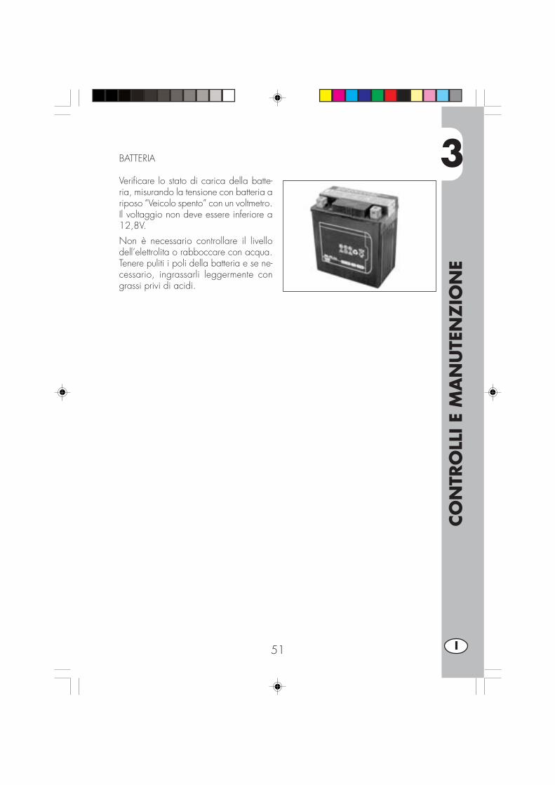
BATTERIA
Verificare lo stato di carica della batte-ria, misurando la tensione con batteria ariposo “Veicolo spento” con un voltmetro.Il voltaggio non deve essere inferiore a12,8V.
Non è necessario controllare il livellodell’elettrolita o rabboccare con acqua.Tenere puliti i poli della batteria e se ne-cessario, ingrassarli leggermente congrassi privi di acidi.
3
CO
NTR
OLL
I E
MA
NU
TEN
ZIO
NE
52I
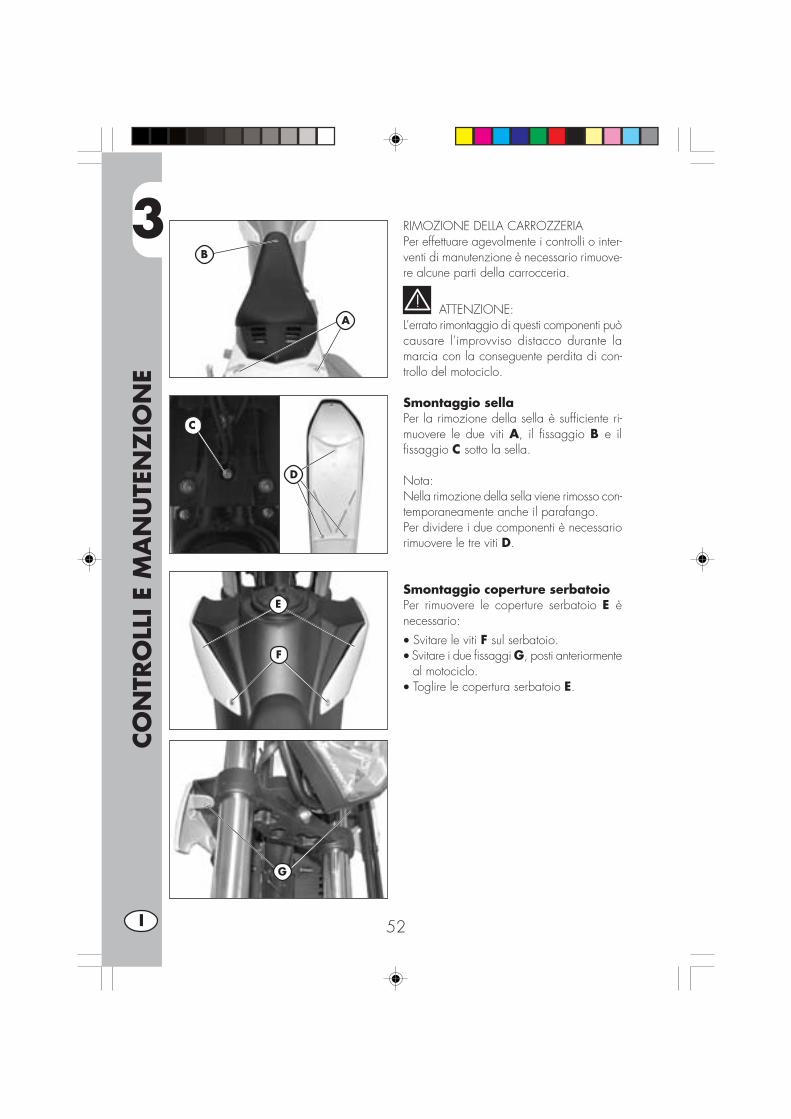
RIMOZIONE DELLA CARROZZERIAPer effettuare agevolmente i controlli o inter-venti di manutenzione è necessario rimuove-re alcune parti della carrocceria.
ATTENZIONE:L’errato rimontaggio di questi componenti puòcausare l’improvviso distacco durante lamarcia con la conseguente perdita di con-trollo del motociclo.
Smontaggio sellaPer la rimozione della sella è sufficiente ri-muovere le due viti A, il fissaggio B e ilfissaggio C sotto la sella.
Nota:Nella rimozione della sella viene rimosso con-temporaneamente anche il parafango.Per dividere i due componenti è necessariorimuovere le tre viti D.
Smontaggio coperture serbatoioPer rimuovere le coperture serbatoio E ènecessario:• Svitare le viti F sul serbatoio.• Svitare i due fissaggi G, posti anteriormente
al motociclo.• Toglire le copertura serbatoio E.
F
A
B
E
G
C
D
3
CO
NTR
OLL
I E
MA
NU
TEN
ZIO
NE
53 I
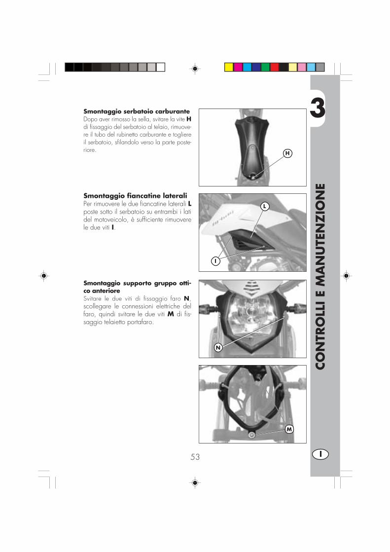
Smontaggio serbatoio carburanteDopo aver rimosso la sella, svitare la vite Hdi fissaggio del serbatoio al telaio, rimuove-re il tubo del rubinetto carburante e togliereil serbatoio, sfilandolo verso la parte poste-riore.
Smontaggio fiancatine lateraliPer rimuovere le due fiancatine laterali Lposte sotto il serbatoio su entrambi i latidel motoveicolo, è sufficiente rimuoverele due viti I.
Smontaggio supporto gruppo otti-co anterioreSvitare le due viti di fissaggio faro N,scollegare le connessioni elettriche delfaro, quindi svitare le due viti M di fis-saggio telaietto portafaro.
H
L
I
N
M

3
CO
NTR
OLL
I E
MA
NU
TEN
ZIO
NE
54I
Smontaggio portatargaE possibile rimuovere il portatarga poste-riore A completo di fanaleria e indicato-ri di direzione, dopo aver rimosso la sel-la e la plastica sotto-sella (vedi paginaprecedente), dopodichè:•Svitare le tre viti e relativi dadi di fissag-gio B del portatarga telaio posteriore.
•Scollegare la connessione elettrica del-la fanaleria posteriore e rimuovere ilportatarga A.
ATTENZIONE:Il veicolo senza portatarga e/o fa-
naleria non è conforme al codice dellastrada vigente. L’uso deve essere limitatoai soli circuiti privati e chiusi dalla circo-lazione
Smontaggio parafango anterioreSmontare il parafango anteriore agendo sulle4 viti C posizionate su entrambi i lati dellaforcella.
Smontaggio cavalletto•Rimuovere la coppia di fissaggio D (vitee dado).
•Estrarre il cavalletto E facendo attenzio-ne alla molla di trazione F.
Note: fare attenzione durante losmontaggio a non danneggiare il ma-gnete e il sensore cavalletto G.
Smontaggio pedane passeggero•Svitare le due viti H indicate in figura erimuovere la pedana passeggero com-pleta di supporto attacco al telaio.
A
B
C
E
D
F
G
H

3
CO
NTR
OLL
I E
MA
NU
TEN
ZIO
NE
55 I
Sostituzione pignone catenaLa descrizione relativa alla sostituzionedel pignone catena riveste un caratterepuramente informativo.Infatti è consigliabile rivolgersi ad un’of-ficina autorizzata BETAMOTOR per ef-fettuare questa operazione.
•Far avanzare la ruota fino a fine corsa,allentando i dadi I (su entrambi i lati) ei registri catena L in modo da poter al-lentare la catena.
•Svitare le 3 viti M di fissaggio del coper-chietto (2 viti per modelli URBAN125).
•Rimuovere la catena dal pignone.
• Inserire la prima marcia e svitare in sen-so antiorario il dado N di fissaggio pi-gnone per URBA200, e i due fissaggiP per URBAN125.
•Rimuovere il pignone catena O e sosti-tuirlo.
•Per il rimontaggio procedere in sensoinverso allo smontaggio.
Nota:Si consiglia di effettuare la sostituzionedel pignone accompagnata da tutto ilgruppo trasmissione.
I
M
O
N
L
M
P
O
URBAN200 URBAN125
URBAN200
URBAN125

3
CO
NTR
OLL
I E
MA
NU
TEN
ZIO
NE
56I
PULIZIA DEL VEICOLO E CONTROLLI
Per ammorbidire lo sporco e il fango depositato sulle superfici verniciate usare ungetto di acqua a bassa pressione. Una volta ammorbiditi, fango e sporcizia devonoessere tolti con una spugna soffice per carrozzeria imbevuta di molta acqua e“shampoo” (2-4% di shampoo in acqua). Successivamente sciacquare abbondante-mente con acqua, ed asciugare con pelle scamosciata. Per l’esterno del motoreservirsi di petrolio, pennello e stracci puliti. Il petrolio è dannoso per la vernice. Siricorda che l’eventuale lucidatura con cere siliconiche deve essere sempre precedu-ta dal lavaggio.
I detersivi inquinano le acque. Pertanto il lavaggio del veicolo va effettuato inzone attrezzate per la raccolta e la depurazione dei liquidi impiegati per illavaggio stesso.
Il lavaggio non deve mai essere eseguito al sole specialmente d’estate quan-do la carrozzeria è ancora calda in quanto lo shampoo, asciugandosi primadel risciacquo, può causare danni alla vernice. Non usare mai stracci imbe-vuti di benzina o nafta per il lavaggio delle superfici verniciate o in materiaplastica, per evitare la perdita della loro brillantezza e delle caratteristichemeccaniche dei materiali.
L’eventuale utilizzo di idropulitrici, può provocare danni alla strumentazione,consigliamo quindi di non indirizzare il getto dell’aqua verso componentielettrici in particolar modo verso il display LCD.
CONTROLLI DOPO LA PULIZIA
Dopo la pulizia del motociclo è buona norma:
•Pulire il filtro dell’aria (procedere come descritto a pag. 48)
• Ingrassare la catena.

3
CO
NTR
OLL
I E
MA
NU
TEN
ZIO
NE
57 I
MANUTENZIONE PROGRAMMATA
AVVERTENZA:
In caso di interventi da eseguire sulla moto rivolgersi alla catena di Assistenza Autorizzata BETAMOTOR.

3
CO
NTR
OLL
I E
MA
NU
TEN
ZIO
NE
58I
LUNGA INATTIVITÀ DEL VEICOLO
In previsione di un lungo periodo di inattività del veicolo, ad esempio durante lastagione invernale, è necessario adottare alcuni semplici accorgimenti a garanziadi un buon mantenimento:•Eseguire un’accurata pulizia del veico-lo in tutte le sue parti.
•Ridurre la pressione dei pneumatici dicirca il 30%, mantenendoli possibilmen-te sollevati da terra.
•Rimuovere la candela ed immettere nelforo qualche goccia di olio motore. Farcompiere qualche giro al motore,azionando la leva di avviamento apedale (dove previsto). Riavvitare lacandela.
•Coprire con un velo d’olio o siliconespray le parti non verniciate, tranne leparti in gomma ed i freni.
•Rimuovere la batteria e conservarla in luo-go asciutto, ricaricandola una volta almese.
•Coprire il veicolo con un telo a prote-zione della polvere.
•Scaricare la vaschetta del carburatoreagendo sull’apposita vite A. Il carbu-rante espulso dalla vaschetta tramite un’apposita tubazione deve essere raccoltoall’interno di un recipiente e immesso nel serbatoio carburante senza disperderlonell’ambiente.
•Serrare nuovamente la vite.
A
DOPO UN LUNGO PERIODO DI INATTIVITÀ
•Riposizionare la batteria e controllarne la tensione con un voltmetro.•Ripristinare la pressione dei pneumatici.•Controllare il serraggio di tutte le viti di una certa importanza meccanica.•Effettuare il primo avviamento con il sistema a pedale: “kick-starter”.
Nota:Il controllo del serraggio delle viti deve essere ripetuto con una frequenza periodica.
A
URBAN200
URBAN125

4
REG
OLA
ZIO
NI
59 I
INDICE ARGOMENTI
CAP. 4 REGOLAZIONI
Regolazione freni
Regolazione frizione
Regolazione minimo
Regolazione gioco gas
Controllo e regolazione gioco sterzo
Tensionamento catena
Fascio luminoso

4
REG
OLA
ZIO
NI
60I
REGOLAZIONE FRENI
Freno anterioreIl freno anteriore è del tipo a disco concomando idraulico per cui non necessitadi alcun intervento di regolazione.
Freno posterioreIl freno posteriore è del tipo a disco concomando idraulico per cui non necessitadi alcun intervento di regolazione.
REGOLAZIONE FRIZIONEL’unica operazione che viene effettuatasulla frizione è la regolazione della posi-zione della leva E.Per effettuare questa regolazione agiresul registro D.Nel caso si effettui la regolazione sullavite a registro è importante, una volta ter-minata, serrare il fermo F in modo dabloccare la vite a registro nella posizio-ne voluta.
Nota:La frizione deve avere un gioco compre-so tra i 0,4 mm e i 0,6 mm.
FD E

4
REG
OLA
ZIO
NI
61 I
REGOLAZIONE MINIMO URBAN200Per eseguire correttamente questa ope-razione, si consiglia di effettuarla a mo-tore caldo, collegando un contagiri elet-tronico al cavo candela. Intervenire poisulla vite di registro A tarando il minimo(n° giri motore 1400 ± 100).
REGOLAZIONE MINIMO URBAN125Per eseguire correttamente questa ope-razione si consiglia di effettuarla a moto-re caldo, collegando un contagiri elet-tronico al cavo candela.Intervenire poi con un giravite sulla vitedi registro C tarando il minimo a 1900 giri.
REGOLAZIONEFLUSSO BENZINA URBAN125/200Per regolare il flusso della benzina oc-corre agire sulla vite D allentandola diun giro e mezzo a partire dalla posizio-ne tutto chiuso.Regolazione standard: dalla posizionedi tutto chiuso (senzo orario) svitare il re-gistro di 1,5 giri
REGOLAZIONE GIOCO GASQualora sul comando dell’acceleratoresia presente una corsa a vuoto superioreai 3 mm misurati sul bordo della mano-pola stessa, occorre effettuarne laregolazione agendo sul registro B dellamanopola.
A
B
C
D
URBAN200
URBAN125
D
4
REG
OLA
ZIO
NI
62I
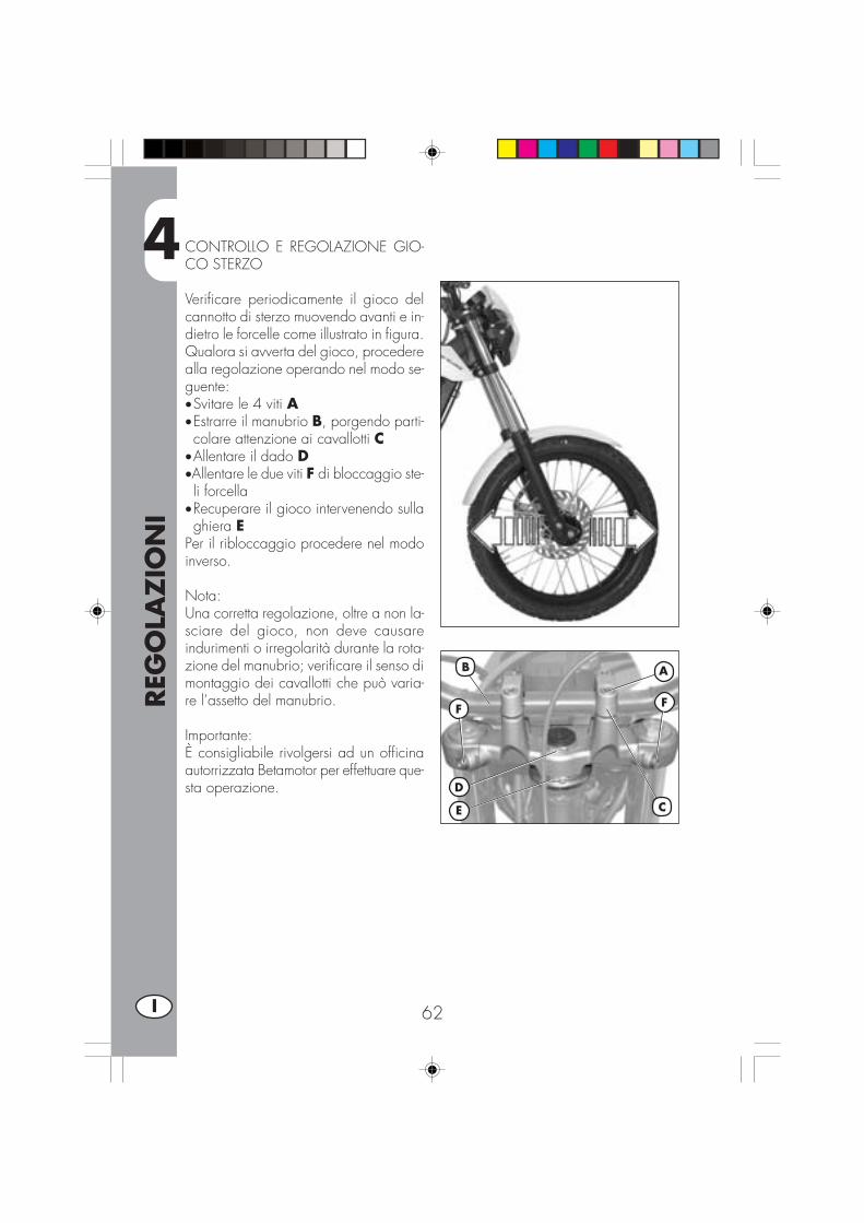
CONTROLLO E REGOLAZIONE GIO-CO STERZO
Verificare periodicamente il gioco delcannotto di sterzo muovendo avanti e in-dietro le forcelle come illustrato in figura.Qualora si avverta del gioco, procederealla regolazione operando nel modo se-guente:•Svitare le 4 viti A•Estrarre il manubrio B, porgendo parti-colare attenzione ai cavallotti C
•Allentare il dado D•Allentare le due viti F di bloccaggio ste-li forcella
•Recuperare il gioco intervenendo sullaghiera E
Per il ribloccaggio procedere nel modoinverso.
Nota:Una corretta regolazione, oltre a non la-sciare del gioco, non deve causareindurimenti o irregolarità durante la rota-zione del manubrio; verificare il senso dimontaggio dei cavallotti che può varia-re l’assetto del manubrio.
Importante:È consigliabile rivolgersi ad un officinaautorrizzata Betamotor per effettuare que-sta operazione.
B
D
E C
A
F F

4
REG
OLA
ZIO
NI
63 I
TENSIONAMENTO CATENA
Per una più lunga durata della catena ditrasmissione è opportuno controllare pe-riodicamente la sua tensione.Tenerla sempre pulita dalla sporcizia de-positata e lubrificarla.Se il gioco della catena supera i 20 mmprocedere al suo tensionamento.
•Allentare il dado A sul i braccio delforcellone
•Allentare il dado C su entrambi i braccidella forcellone
•Agire sul dado B fino al raggiungimentodella tensione desiderata della catena
•Procedere analogamente agendo suldado B situato sull’altro braccio delforcellone fino ad ottenere il perfetto al-lineamento della ruota
•Serrare i dado B e A su entrambi i brac-ci del forcellone.
20 mm
B
C A

4
REG
OLA
ZIO
NI
64I
FASCIO LUMINOSO
• La regolazione del fascio luminoso avviene manualmente dopo aver allentato leviti A poste sui lati del gruppo ottico
• L’orientamento del fascio luminoso va verificato periodicamente. La regolazione èsoltanto verticale
•Porre il veicolo (in piano, ma non sul cavalletto) a 10 m da una parete verticale
•Misurare l’altezza dal centro del proiettore a terra e riportarla con una crocetta sulmuro a 9/10 dall’altezza del faro
•Accendere la luce anabbagliante, sedersi sulla moto e verificare che il fascioluminoso proiettato sulla parete sia di poco al di sotto della crocetta riportata sulmuro.
9/10
h
10 m
h
AA

5
SOST
ITU
ZIO
NI
65 I
INDICE ARGOMENTI
CAP. 5 SOSTITUZIONI
Sostituzione pastiglie freni
Sostituzione lampade faro anteriore
Sostituzione lampade faro posteriore
Sostituzione lampade indicatori di direzione
Caratteristiche lampade

5
SOST
ITU
ZIO
NI
66I
SOSTITUZIONE PASTIGLIE FRENI
La descrizione relativa alla sostituzionedelle pastiglie, riveste un carattere pura-mente informativo; infatti è consigliabilerivolgersi ad un’officina autorizzataBETAMOTOR per effettuare questa ope-razione.
Freno anteriorePer la sostituzione delle pastiglie anterio-ri occorre procedere nel seguente modo:
•Smontare la pinza svitando le due viti A•Svitare le due viti B
Nota: le viti B sono serrate molto forte,è consigliabile allentarle prima di sgan-ciare la pinza dalla forcella
•Estrarre le pastiglie
•Per il rimontaggio procedere in sensoinverso.
Note:Fare attenzione che la molla D in figurasia bene posizionata nella propria sede,essa dovrà offrire un po’ di resistenza alposizionamento delle pastiglie.
Prestare particolare attenzione ad effet-tuare correttamente il rimontaggio delleviti per evitare problemi di frenata.
Nel caso di rimozione del disco freno,nel rimontaggio applicare della loctite alleviti.
Durante lo smontaggio della pinza frenofare attenzione a non danneggiare il reedC poiché è molto delicato.
CD
A
B
B

5
SOST
ITU
ZIO
NI
67 I
Freno posteriorePer la sostituzione delle pastiglie poste-riori occorre procedere nel seguentemodo:
•Rimuovere Il grano di sicurezza A
•Svitare il perno di sostegno pastignie B•Rimuovere le pastiglie C.
•Per il rimontaggio procedere in sensoinverso, prestando particolare attenzio-ne al corretto riposizionamento dellepastiglie nella propria sede.
Nota:Per la sostituzione delle pastiglie freno esempre consigliabile rivolgersi ad unaofficina autorizzata BETAMOTOR.
A
B
C

5
SOST
ITU
ZIO
NI
68I
SOSTITUZIONE LAMPADA DEL FAROANTERIOREPer la sostituzione delle lampade faroanteriori occorre procedere nel seguen-te modo:
•Rimuovere le due viti A di fissaggio delgruppo ottico completto al supporto.
•Scollegare il connettore elettrico B
•Sollevare la cuffia in gomma C•Sganciare la molla D
•Rimuovere la lampada difettosa e inse-rirne una nuova avendo cura di non toc-care il bulbo per evitare di compromet-tere l’efficienza.
•Per la lampada di posizione è sufficientesfilare il bulbo E e sfilare la lampadinadifettosa.
•Per il rimontaggio procedere in sensoinverso.
Nota:Tulle le lampade devono essere sostituitecon altre di uguali caratteristiche (Vediparagrafo “Caratteristiche lampade pa-gina 76).
AA
B
C
C
D
E
5
SOST
ITU
ZIO
NI
69 I
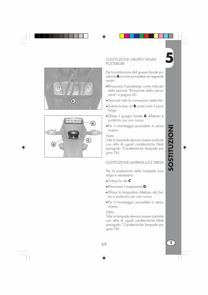
SOSTITUZIONE GRUPPO FANALEPOSTERIORE
Per la sostituzione dell gruppo fanale po-steriore A occorre procedere nel seguentemodo:
•Rimuovere il portatarga come indicatonella sezione “Rimozione della carroz-zeria” a pagina 60
•Staccare tutte le connessioni elettriche
•Svitare le due viti B poste sotto il para-fango
•Sfilare il gruppo fanale A difettoso esostituirlo con uno nuovo.
•Per il rimontaggio procedere in sensoinverso.
Nota:Tulle le lampade devono essere sostituitecon altre di uguali caratteristiche (Vediparagrafo “Caratteristiche lampade pa-gina 76).
SOSTITUZIONE LAMPADA LUCE TARGA
Per la sostituzione della lampada lucetarga e necessario:
•Svitare la vite C•Rimuovere il trasparente D
•Sfilare la lampadina difettosa dal bul-bo e sostituirla con una nuova.
•Per il rimontaggio procedere in sensoinverso.
Nota:Tulle le lampade devono essere sostituitecon altre di uguali caratteristiche (Vediparagrafo “Caratteristiche lampade pa-gina 76).
A
B
CD
5
SOST
ITU
ZIO
NI
70I
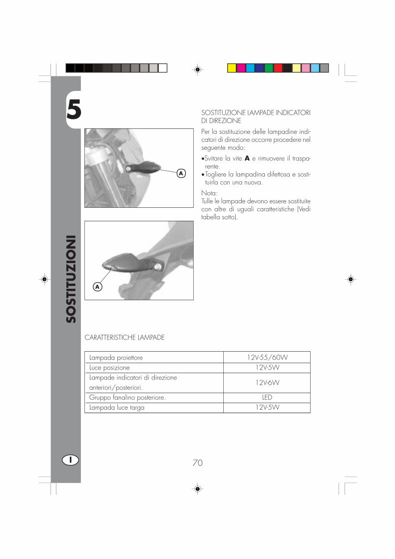
SOSTITUZIONE LAMPADE INDICATORIDI DIREZIONE
Per la sostituzione delle lampadine indi-catori di direzione occorre procedere nelseguente modo:
•Svitare la vite A e rimuovere il traspa-rente.
•Togliere la lampadina difettosa e sosti-tuirla con una nuova.
Nota:Tulle le lampade devono essere sostituitecon altre di uguali caratteristiche (Veditabella sotto).
A
A
Lampada proiettore 12V-55/60WLuce posizione 12V-5WLampade indicatori di direzioneanteriori/posteriori.
12V-6W
Gruppo fanalino posteriore. LEDLampada luce targa 12V-5W
CARATTERISTICHE LAMPADE

6
CO
SA F
ARE
IN C
ASO
DI EM
ERG
ENZ
A
71 I
INDICE ARGOMENTI
CAP. 6 COSA FARE IN CASO DI EMERGENZA
INDICE ALFABETICO

6
CO
SA F
ARE
IN C
ASO
DI EM
ERG
ENZ
A
72I
INCONVENIENTE CAUSA
Il motore non si avvia
RIMEDIO
- Impianto di alimentazionecarburante ostruito (tubi,serbatoio benzina, rubinetto)
- Filtro aria eccessivamentesporco
- Non arriva corrente alla candela
- Motore ingolfato
Effettuare la pulizia dell’impianto
Operare come indicato a pag. 48
Effettuare la pulizia o la sostituzionedella candela. Se il problema persisterivolgersi ad un nostro Concessionario
Con il gas tutto aperto insistere peralcuni istanti nella messa in moto. Senon si ottengono risultati occorresmontare la candela ed asciugarla
Il motore perde colpi - Candela con distanza elettrodiirregolare
- Candela sporca
Ripristinare la corretta distanza tra glielettrodi
Pulire o sostituire la candela
Il pistone batte in testa - Accensione troppo anticipata
- Presenza di depositi carboniosiall’interno del cilindro o sullacandela
Verificare la fase
Rivolgersi ad un nostro Concessiona-rio
Il motore si surriscalda eperde potenza
- Marmitta in parte ostruita
- Luce di scarico ostruita
- Accensione ritardata
Rivolgersi ad un nostroConcessionario
Rivolgersi ad un nostroConcessionario
Verificare la fase
Frenata anteriore scarsa - Pastiglie usurate
- Presenza di aria o umidità nelcircuito idraulico
Operare come indicato a pag. 66
Operare come indicato a pag. 46
Frenata posteriore scarsa - Pastiglie usurate
- Presenza di aria o umidità nelcircuito idraulico
Operare come indicato a pag. 66
Operare come indicato a pag. 46

IND
ICE
ALF
ABET
ICO
73 I
Avviamento ......................................................................................... 38
Candela............................................................................................. 49Chiavi e serrature ................................................................................. 12Commutatore / bloccasterzo ................................................................. 12Controlli dopo la pulizia ........................................................................ 56Controlli e manutenzione prima e dopo utilizzo in fuoristrada ....................... 36Cruscotto e comandi ............................................................................ 13
Dati identificazione veicolo ...................................................................... 8Dati tecnici ......................................................................................... 24
Filtro aria ............................................................................................ 48Freno anteriore: controllo e sostituzione ............................................. 50 - 66Freno posteriore: controllo e sostituzione ............................................ 50 - 66
Lubrificanti e liquidi consigliati ................................................................ 37LCD (istruzioni di settaggio e funzionamento tachimetro digitale) ................... 14
Manutenzione programmata .................................................................. 57
Olio motore: controllo e sostituzione URBAN200 ....................................... 42Olio motore: controllo e sostituzione URBAN125 ....................................... 44Olio pompa freni ................................................................................. 45Olio forcelle ........................................................................................ 47
Regolazione fascio luminoso .................................................................. 64Regolazione freni ................................................................................. 60Regolazione frizione ............................................................................. 60Regolazione flusso benzina (solo per URBAN125) ..................................... 61Regolazione gioco gas ......................................................................... 61Regolazione minimo ............................................................................. 61Ricerca del guasto................................................................................ 71Rifornimento carburante ......................................................................... 40Rodaggio ........................................................................................... 37
Schema elettrico URBAN125 ................................................................. 28Schema elettrico URBAN200 ................................................................. 30Serratura casco ................................................................................... 12Sostituzione lampade ............................................................................ 68Spurgo freni ........................................................................................ 45Sterzo: controllo e regolazione ............................................................... 62
Tensionamento catena ........................................................................... 63


1 GB
URBAN 125/200 cc
Thanks for you preference, and have a good time! This hand-book contains the information you need to properly operate andmaintain your motorcycle.
The data and specifications provided in this manual does not constitute anengagement on the part of BETAMOTOR S.p.A. BETAMOTOR reserves theright to make any changes and improvements to its models at any momentand without notice.

2GB
IMPORTANT
We recommend checking all the tightenings after the first one ortwo hours’ ride over rough ground. Special attention should bepaid to the following parts:
• rear sprocket• footrest supports• front brake caliper• rear disk brake caliper• plate holder• u-bolt for handlebar fastening• mudguard bracket• engine bolts• shock absorber bolts• wheel spokes• rear frame• Fairings
IMPORTANT
For any servicing requirements, please contact Betamotor’s au-thorized service network.
CO
NTE
NTS
3 GB
Operating notes.................................................................................... 5Ecologic guide ..................................................................................... 5Riding safety ........................................................................................ 6
CHAPTER 1 GENERAL INFORMATION ....................................... 7Vehicle identification data ....................................................................... 8Delivery .............................................................................................. 8Load ................................................................................................... 9Tyres ................................................................................................... 9Familiarizing with your vehicle ............................................................... 10Keys ................................................................................................. 12Ignition switch / Steering lock ............................................................... 12Helmet lock ........................................................................................ 12Instrument panel and controls .................................................................. 13Speedometer setting and operating istructions ........................................... 14General specifications .......................................................................... 24Engine specifications URBAN 125 .......................................................... 26Engine specifications URBAN 200 .......................................................... 27Wiring diagrams URBAN 125 .............................................................. 28Wiring diagrams URBAN 200 .............................................................. 30Electrical devices ................................................................................ 32AIS Valve ............................................................................................ 34
CHAPTER 2 OPERATION ......................................................... 35Checks and maintenance before and after off-road use .............................. 36Recommended lubricants and fluids ........................................................ 37Running-in .......................................................................................... 37Starting the engine .............................................................................. 38Choke ............................................................................................... 39Shutting off the engine ......................................................................... 39Refuelling........................................................................................... 40
CHAPTER 3 CHECKS AND MAINTENANCE ............................... 41Engine oil and oil filter URBAN 200 ....................................................... 42Engine oil URBAN 125 ......................................................................... 44Fume collecting tube ............................................................................ 45Brake pump oil - Bleeding the brakes ...................................................... 46Fork oil .............................................................................................. 47Air filter ............................................................................................. 48Spark plug ......................................................................................... 49Brakes .............................................................................................. 50Battery .............................................................................................. 51Removing the bodywork ....................................................................... 52Cleaning and checking the vehicle ......................................................... 56Scheduled maintenance ....................................................................... 57Prolonged inactivity ............................................................................. 58

CO
NTE
NTS
4GB
CHAPTER 4 ADJUSTMENTS ..................................................... 58Adjusting the brakes ............................................................................ 60Adjusting the clutch .............................................................................. 60Adjusting the slow running .................................................................... 61Fuel flow adjustment ............................................................................. 61Adjusting the throttle play ...................................................................... 61Checking and adjusting the steering play ................................................ 62Tensioning the chain ............................................................................ 63Adjusting the headlight ......................................................................... 64
CHAPTER 5 REPLACEMENTS ................................................... 65Replacing the brake pads ..................................................................... 66Replacing the headlight bulb ................................................................. 68Replacing the rear light bulb .................................................................. 69Replacing the pate Illumination ............................................................... 69Replacing the turn indicator bulbs ........................................................... 70Bulbs characteristics .............................................................................. 70
CHAPTER 6 TROUBLESHOOTING ............................................ 71
INDEX.................................................................................... 73

5 GB
OPERATING NOTES•The vehicle must be accompanied by: number-plate, registration document, taxdisc and insurance.
•Do not carry any animals or objects which are not securely fastened to the vehicle,or exceed the vehicle’s overall dimensions or the maximum load specified by themanufacturer.
•Riding without a helmet is forbidden.•Any modifications of the engine or other parts resulting in a power and/or speedincrease are punishable by severe sanctions including the confiscation of the vehi-cle.
•To protect your safety and that of others, always wear a helmet and adopt a saferiding conduct.
WARNINGAny modifications and tampering with the vehicle during the warranty periodexempt the manufacturer from all responsibility and make the warranty null andvoid.
ECOLOGIC GUIDE•Every vehicle powered by an internal combustion engine produces an amount ofnoise (noise pollution) and gases (air pollution) which varies with the riding style.
•The abatement of noise and air pollution levels is the duty of everybody. Avoid full-throttle starts, sudden acceleration and abrupt braking. This will reduce noise emis-sion as well as the wear and tear of the tyres and mechanical parts, and will alsoallow a considerable reduction in fuel consumption.

6GB
RIDING SAFETY
•Observe the Highway Code.
•Always put on and fasten a homologated helmet.
•Always keep the helmet visor clean.
•Avoid wearing garments with hanging ends.
•Do not keep sharp or brittle objects in your pockets while riding.
•Be sure to correctly adjust the rearview mirrors.
•Always ride in a seated position, with both hands on the handlebars and both feeton the footrests.
•Always pay attention and do not allow anything to distract you while riding.
•Do not eat, drink, smoke, use a mobile phone, etc. while riding.
•Do not wear headphones to listen to music while riding.
•Never ride abreast with other vehicles.
•Do not tow and avoid being towed by other vehicles.
•Always keep a safe distance from other vehicles.
•Ride with the lights (low beam) on, even during the day.
•Do not sit on the vehicle when it is on its stand.
•Do not start off while the vehicle is on its stand.
•Do not pull out the stand when the vehicle is facing downhill.
•Avoid swaying and wheelies as they are extremely dangerous for your own andother people’s safety as well as for your vehicle.
•Always apply both brakes on dry roads with no gravel and sand. Using one brakemay result in dangerous and uncontrolled skidding.
•To reduce the braking distance, always apply both brakes.
•On wet roads, ride at moderate speed and be very careful, especially whenapplying the brakes.
•Do not start the engine in closed places.
1
GEN
ERA
L IN
FORM
ATI
ON
7 GB
CONTENTS
CHAPTER 1 GENERAL INFORMATION
Vehicle identification data
Delivery
Load
Tyres
Familiarizing with your vehicle
Keys
Ignition switch / Steering lock
Helmet lock
Instrument panel and controls
Speedometer setting and operating istructions
Specifications
Wiring diagram
Electrical devices
AIS Valve
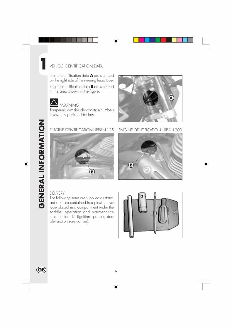
1
GEN
ERA
L IN
FORM
ATI
ON
8GB
VEHICLE IDENTIFICATION DATA
Frame identification data A are stampedon the right side of the steering head tube.
Engine identification data B are stampedin the area shown in the figure.
WARNINGTampering with the identification numbersis severely punished by law.
ENGINE IDENTIFICATION URBAN 200
DELIVERYThe following items are supplied as stand-ard and are contained in a plastic enve-lope placed in a compartment under thesaddle: operation and maintenancemanual, tool kit (ignition spanner, dou-ble-function screwdriver).
ENGINE IDENTIFICATION URBAN 125
A
B
B

1
GEN
ERA
L IN
FORM
ATI
ON
9 GB
LOAD
•Maximum load (rider + passenger): 280 kg.•To avoid making the vehicle unstable, do not carry bulky or heavy objects.•Do not carry objects that stick from the vehicle or cover the lighting and signallingdevices.
•The helmet must be put in its compartment with the top facing downwards.
WARNING•For your riding safety, frequently check the tyres.•Keep the tyre pressures within the prescribed range.•Check the tyre pressures every other week.•Always measure the inflating pressures when the tyres are cold.•Before riding, check the tyres for cuts, cracks, abrasions, bulges, etc. If any defectsare found, have the tyres checked by an expert as riding with a damaged tyre canbe extremely dangerous.
• If a tyre gets punctured, stop the vehicle immediately. Riding with a flat tyre isdangerous and may seriously damage the tyre itself and the wheel rim.
•Higher inflating pressures are recommended when riding in maximum load condition.•The tyre (TUBE TYPE) tread depth must never be less than 2 mm.Failure to comply with this rule is punished under the regulations in force.
TYRES
Tyre Front Rear Size 80/100 - 19 49P 120/90-16 63P Pressure 1,4 ÷1,5 bar 1,5 ÷1,6 bar
Pressure is too low Pressure is too higtpressure is correct

1
GEN
ERA
L IN
FORM
ATI
ON
10GB
FAMIALIARIZING WITH THE VEHICLE
1
2
34
5
7
8
9
19
20
13
14
10
15
16
12
17
11
11
18
21
22
24
25
24
17
6

1
GEN
ERA
L IN
FORM
ATI
ON
11 GB
FAMILIARIZING WITH THE VEHICLE:
1 - Air filter2 - Fuel tank3 - Filler cap4 - Silencer5 - Rear damper6 - Faro anteriore7 - Front turn signal lamp.8 - Tail lamp
9 - Rear turn signal lamp.
10 - Side stand11 - Rearview mirror12 - Passenger footrest13 - Fork14 - Footrest15 - Saddle16 - Engine17 - Front mudguard18 - Name-plate bracket19 - Start. lever20 - Helmet security lock21 - Frame22 - Chain23 - Chain guard24 - Front disk brake caliper25 - Rear disk brake caliper
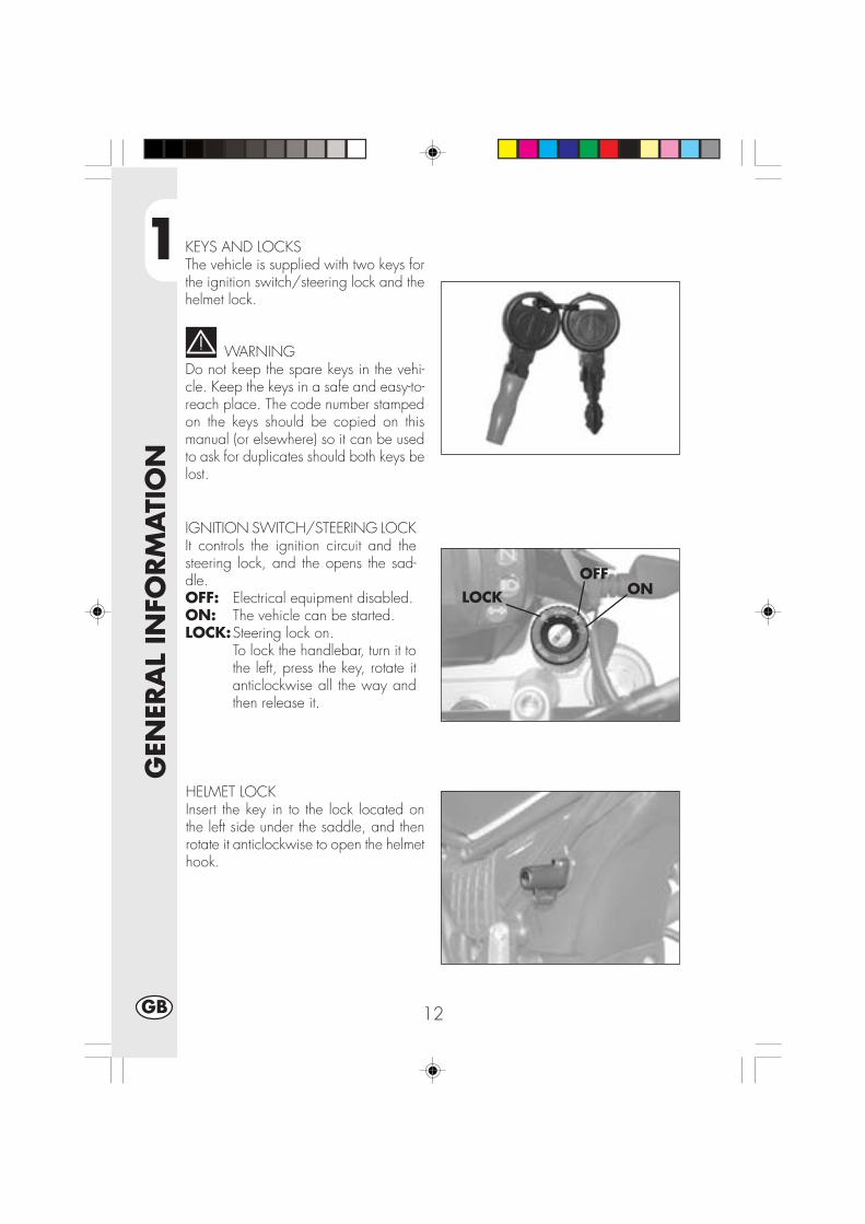
1
GEN
ERA
L IN
FORM
ATI
ON
12GB
KEYS AND LOCKSThe vehicle is supplied with two keys forthe ignition switch/steering lock and thehelmet lock.
WARNINGDo not keep the spare keys in the vehi-cle. Keep the keys in a safe and easy-to-reach place. The code number stampedon the keys should be copied on thismanual (or elsewhere) so it can be usedto ask for duplicates should both keys belost.
IGNITION SWITCH/STEERING LOCKIt controls the ignition circuit and thesteering lock, and the opens the sad-dle.OFF: Electrical equipment disabled.ON: The vehicle can be started.LOCK:Steering lock on.
To lock the handlebar, turn it tothe left, press the key, rotate itanticlockwise all the way andthen release it.
HELMET LOCKInsert the key in to the lock located onthe left side under the saddle, and thenrotate it anticlockwise to open the helmethook.
ONOFF
LOCK

1
GEN
ERA
L IN
FORM
ATI
ON
13 GB
INSTRUMENT PANEL AND CONTROLS
Note: The lighting of the stand warning light indicates that the stand is down. Forsafety reasons, the engine stops as soon as the gears are engaged.
2
10
11
8
1
9
6
3
5
4
7
12
13
14
15
16
17
1- LCD2- Key operated switch3- Neutral indicator light4- Trafficator lights tell tale lamp5- Headlight tell tale lamp6- Tell tale lamp central stand7- SCROLL Pushbutton8- Clutch lever9- Choke unit lever (Urban125)
10- Front brake lever11 - Throttle twist grip12 - Starting button13 - Engine stop button14 - Direction indicators pushbutton15 - Horn button16 - Headlight selector17 - Passing

1
GEN
ERA
L IN
FORM
ATI
ON
14GB
HOT TO SET AND USE THE ODOMETER
TABLE OF CONTENTS
ECTION CONTENT
10.0 Initial test and main screen
10.1 Warning lights
10.2 Instant speed and total distance (ODO)
20.0 Secondary functions
20.1 Trip odometer (TRP)
20.2 Clock (CLK)
20.3 Chronometer (LAP)
20.4 Max speed (MAX)
30.0 Storage
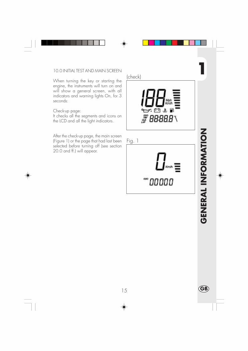
1
GEN
ERA
L IN
FORM
ATI
ON
15 GB
10.0 INITIAL TEST AND MAIN SCREEN
When turning the key or starting theengine, the instruments will turn on andwill show a general screen, with allindicators and warning lights On, for 3seconds:
Check-up page:It checks all the segments and icons onthe LCD and all the light indicators.
After the check-up page, the main screen(Figure 1) or the page that had last beenselected before turning off (see section20.0 and ff.) will appear.
(check)
Fig. 1
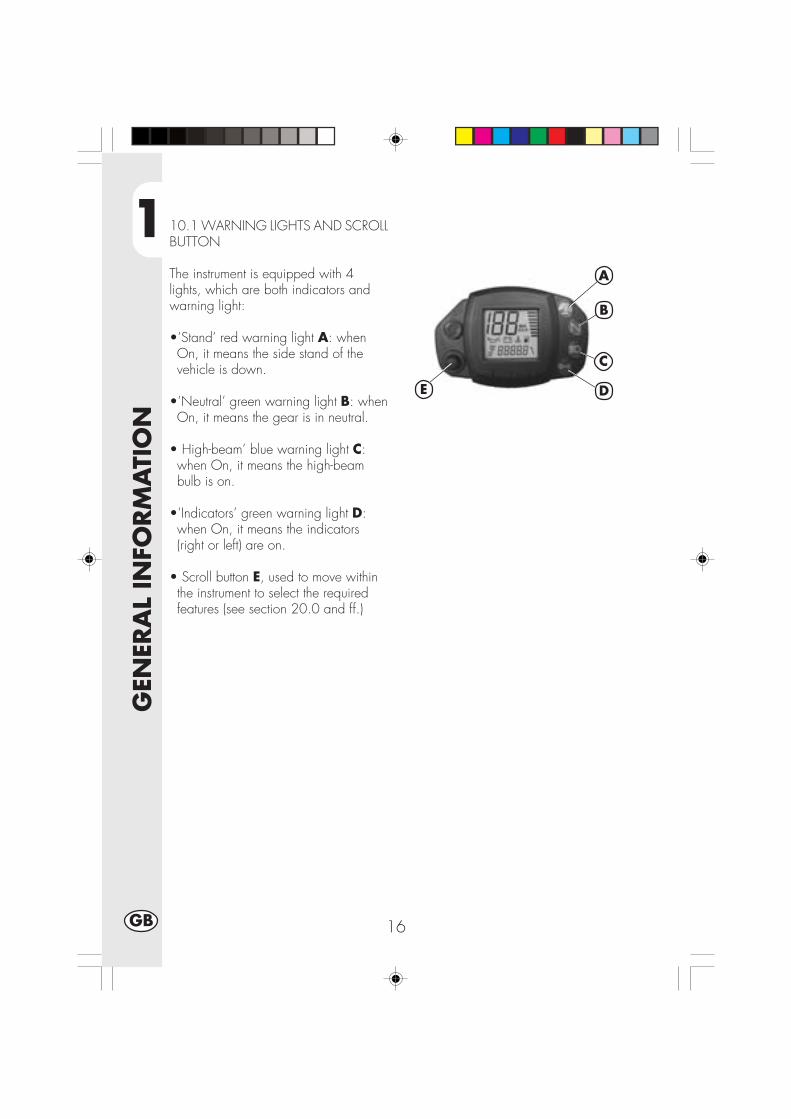
1
GEN
ERA
L IN
FORM
ATI
ON
16GB
10.1 WARNING LIGHTS AND SCROLLBUTTON
The instrument is equipped with 4lights, which are both indicators andwarning light:
•’Stand’ red warning light A: whenOn, it means the side stand of thevehicle is down.
•’Neutral’ green warning light B: whenOn, it means the gear is in neutral.
• High-beam’ blue warning light C:when On, it means the high-beambulb is on.
•’Indicators’ green warning light D:when On, it means the indicators(right or left) are on.
• Scroll button E, used to move withinthe instrument to select the requiredfeatures (see section 20.0 and ff.)
A
B
C
DE
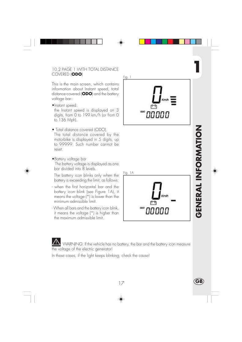
1
GEN
ERA
L IN
FORM
ATI
ON
17 GB
Fig. 1
Fig. 1A
10.2 PAGE 1 WITH TOTAL DISTANCECOVERED (ODO)
This is the main screen, which containsinformation about Instant speed, totaldistance covered (ODO) and the batteryvoltage bar:
•Instant speed:the Instant speed is displayed on 3digits, from 0 to 199 km/h (or from 0to 136 Mph).
• Total distance covered (ODO).The total distance covered by themotorbike is displayed in 5 digits, upto 99999. Such number cannot bereset.
•Battery voltage bar The battery voltage is displayed as onebar divided into 8 levels.
The battery icon blinks only when thebattery is exceeding the limit, as follows:
- when the first horizontal bar and thebattery icon blink (see Figure 1A), itmeans the voltage (*) is lower than theminimum admissible limit.
- When all bars and the battery icon blink,it means the voltage (*) is higher thanthe maximum admissible limit.
WARNING: If the vehicle has no battery, the bar and the battery icon measurethe voltage of the electric generator!
In these cases, if the light keeps blinking, check the cause!

1
GEN
ERA
L IN
FORM
ATI
ON
18GB
20.0 SECONDARY FUNCTIONS
The main screen provides access to the following secondary features, containinginformation in the following sequence:
Trip odometer (TRP)
Clock (CLK)
Chronometer (LAP)
Max speed (MAX)
In addition to the specific information, the screen will still show the instant speed andthe battery voltage bar/icon.
From the general screen (ODO), quickly press SCROLL to have access to the otherscreens. This means they will be displayed in the following sequence:
ODO -> TRP -> CLK -> LAP -> MAX
When pressing SCROLL when the max speed screen is on (MAX) the screen willgo back to the main page (ODO) and the sequence can be resumed anywhere.
WARNING:THE SCROLL BUTTON CANNOT BE PRESSED WHEN THE VEHICLE IS RUNNING,I.E. WHEN THE INSTANT SPEED IS OTHER THAN 0 km/h-mph.
THIS IS FOR THE DRIVER’S SAFETY.

1
GEN
ERA
L IN
FORM
ATI
ON
19 GB
Fig. 2
20.1 TRIP ODOMETER TRP
With the vehicle off, from Figure 1,quickly press SCROLL to go to figure 2,providing information on instant speed,subtotal distance covered (TRP) and thebattery voltage bar:
• Km/h (Mph) in 3 digits (large).
• Trip odometer TRP in 4 digits (small)
• battery voltage bar
The trip odometer uses 4 digits in the000.0 format to measure the subtotaldistance covered from 0.0 Km/Miles to999.9 Km/Miles. When reaching999.9, the odometer will automaticallygo back to 0.0 as soon as coveringanother 0.1 km or mile.
The odometer can be manually reset (withFigure 2 On) with the vehicle off bypressing SCROLL for about 3 secondsuntil “—.-“ appears in the 4 small digits.
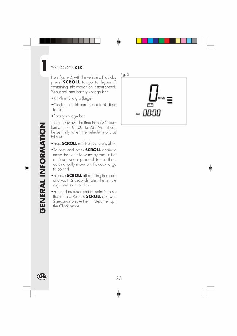
1
GEN
ERA
L IN
FORM
ATI
ON
20GB
Fig. 3
20.2 CLOCK CLK
From figure 2, with the vehicle off, quicklypress SCROLL to go to figure 3containing information on Instant speed,24h clock and battery voltage bar:
•Km/h in 3 digits (large)
•Clock in the hh:mm format in 4 digits(small)
•Battery voltage bar
The clock shows the time in the 24 hoursformat (from 0h:00’ to 23h:59’); it canbe set only when the vehicle is off, asfollows:
•Press SCROLL until the hour digits blink.
•Release and press SCROLL again tomove the hours forward by one unit ata time. Keep pressed to let themautomatically move on. Release to goto point 4.
•Release SCROLL after setting the hoursand wait: 2 seconds later, the minutedigits will start to blink.
•Proceed as described at point 2 to setthe minutes. Release SCROLL and wait2 seconds to save the minutes, then quitthe Clock mode.

1
GEN
ERA
L IN
FORM
ATI
ON
21 GB
Fig. 4
20.3 CHRONOMETER LAP
From figure 3, with the motorbike off,quickly press the button to go to figure 4,containing information on Instant speed,the chronometer in minutes:seconds andthe battery voltage bar:
•Km/h in 3 digits (large)
•Chronometer in the mm:ss format in 4digits (small)
• Battery voltage bar.
When the screen looks as in “Figure 4”,it means the chronometer must beactivated before it can be used. To dothis, press SCROLL and keep it pressedfor more than 1 second until “—:—“disappears and the chronometer appearsin the MINUTES:SECONDS format, asdescribed in figure 4A”
Fig. 4A
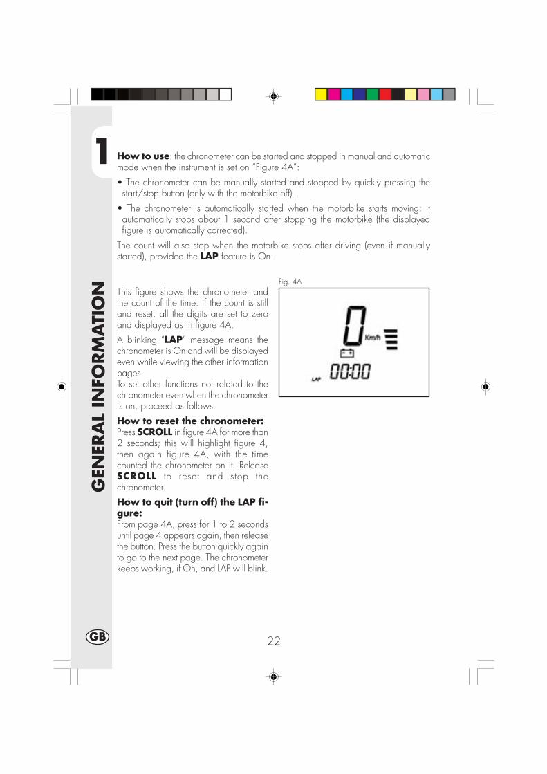
1
GEN
ERA
L IN
FORM
ATI
ON
22GB
How to use: the chronometer can be started and stopped in manual and automaticmode when the instrument is set on “Figure 4A”:
• The chronometer can be manually started and stopped by quickly pressing thestart/stop button (only with the motorbike off).
• The chronometer is automatically started when the motorbike starts moving; itautomatically stops about 1 second after stopping the motorbike (the displayedfigure is automatically corrected).
The count will also stop when the motorbike stops after driving (even if manuallystarted), provided the LAP feature is On.
Fig. 4AThis figure shows the chronometer andthe count of the time: if the count is stilland reset, all the digits are set to zeroand displayed as in figure 4A.
A blinking “LAP” message means thechronometer is On and will be displayedeven while viewing the other informationpages.To set other functions not related to thechronometer even when the chronometeris on, proceed as follows.
How to reset the chronometer:Press SCROLL in figure 4A for more than2 seconds; this will highlight figure 4,then again figure 4A, with the timecounted the chronometer on it. ReleaseSCROLL to reset and stop thechronometer.
How to quit (turn off) the LAP fi-gure:From page 4A, press for 1 to 2 secondsuntil page 4 appears again, then releasethe button. Press the button quickly againto go to the next page. The chronometerkeeps working, if On, and LAP will blink.
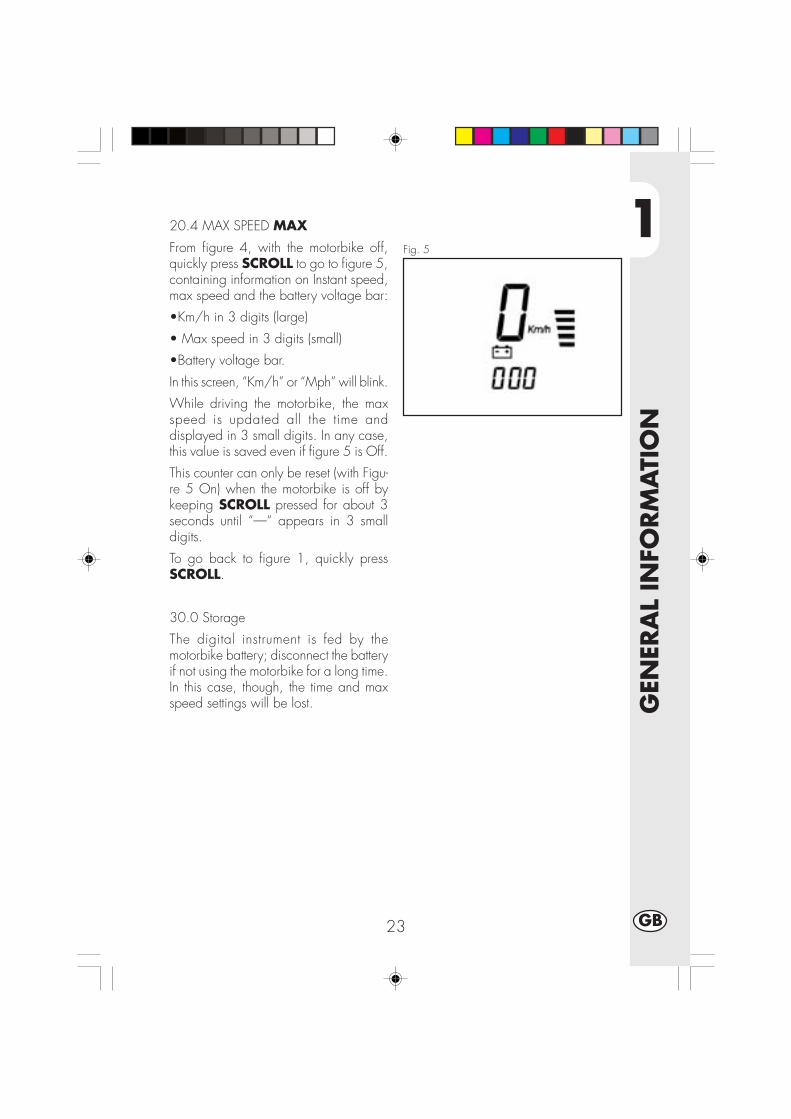
1
GEN
ERA
L IN
FORM
ATI
ON
23 GB
Fig. 5
20.4 MAX SPEED MAX
From figure 4, with the motorbike off,quickly press SCROLL to go to figure 5,containing information on Instant speed,max speed and the battery voltage bar:
•Km/h in 3 digits (large)
• Max speed in 3 digits (small)
•Battery voltage bar.
In this screen, “Km/h” or “Mph” will blink.
While driving the motorbike, the maxspeed is updated all the time anddisplayed in 3 small digits. In any case,this value is saved even if figure 5 is Off.
This counter can only be reset (with Figu-re 5 On) when the motorbike is off bykeeping SCROLL pressed for about 3seconds until “—“ appears in 3 smalldigits.
To go back to figure 1, quickly pressSCROLL.
30.0 Storage
The digital instrument is fed by themotorbike battery; disconnect the batteryif not using the motorbike for a long time.In this case, though, the time and maxspeed settings will be lost.

1
GEN
ERA
L IN
FORM
ATI
ON
24GB
SPECIFICATIONS
MAXIMUM LOADrider + passenger.......................................................................... 280 kg
VEHICLE’S KERB (DRY) WEIGHT URBAN 200 .................................... 103 kg
VEHICLE’S KERB (DRY) WEIGHT URBAN 125 ..................................... 101 kg
DIMENSIONSoverall length .......................................................................... 2,143 mm
overall width .............................................................................. 820 mm
overall height .......................................................................... 1,170 mm
wheelbase .............................................................................. 1,372 mm
saddle height ............................................................................. 836 mm
ground clearance ........................................................................ 288 mm
FRAME.............................................................. steel, double closed cradle
CAPACITIESfuel tank .............................................................................................. 6
including reserve ................................................................................ 1.5
average consumption .................................................................... 25 km/l
1
GEN
ERA
L IN
FORM
ATI
ON
25 GB
FRONT SUSPENSION
Hydraulic fork with Ø 37 mm.
Amount of oil per stem:
left ....................................................................................... 310 ± 5 cc
right ..................................................................................... 310 ± 5 cc
Oil type ............................................................................. SHELL EBH16
or LIQUI MOLY RECING SUSPENSION OIL SAE 10WOil level ......................................................... 142 mm from tube upper rim
with fork at end of travel and no spring
Trail ......................................................................................... 82,5 mm
REAR SUSPENSIONSingle progressive hydraulic shock absorber with adjustable rebound and springpreloadshock absorber travel ..................................................................... 63 mm
FRONT BRAKEØ 245 mm disc brake with hydraulic control
REAR BRAKEØ 220 mm disc brake with hydraulic control

1
GEN
ERA
L IN
FORM
ATI
ON
26GB
ENGINE URBAN 125
Type ................................ Single-cylinder, forward-inclined, four-stroke, SOHC
Bore x stroke ............................................................................ 54X54 mm
Displacement .............................................................................. 124 cm3
Compression ratio ............................................................................. 10:1
Carburettor ....................................................MIKUNI UCAL 5Nh Ø 26-38
Lubrication ............................................................................... oil in sump
Fuel system .... petrol (unleaded, with a minimum octane number of 95), by carburettor
Cooling system ................................................................. by air circulation
Spark plug ........................................................................ NGK DR7 HSA
Clutch ..................................................................... multiple-disc in oil bath
transmission ............................................. 5-speed, with constant-mesh gears
Primary gearbox ratio ..................................................................... 68/20
Final gearbox ratio ......................................................................... 60/14
Gear ratios 1st ...................................................................... 37/14
2nd..................................................................... 32/18
3rd ..................................................................... 25/19
4th ...................................................................... 23/22
5th ...................................................................... 21/24
Drive chain ..................................................... REGINA 1/2, 5/16 P. 136
Play of valves ...................... intake mm 0.08 - 0.12 , exhaust mm 0,10 - 0,14
Starting ................................................................. electric and/or kick-start
Engine oil ............................................................. BARDAHL XTM15W 50
Engine oil capacity ...................................................... 1,000 ml/1,050 ml
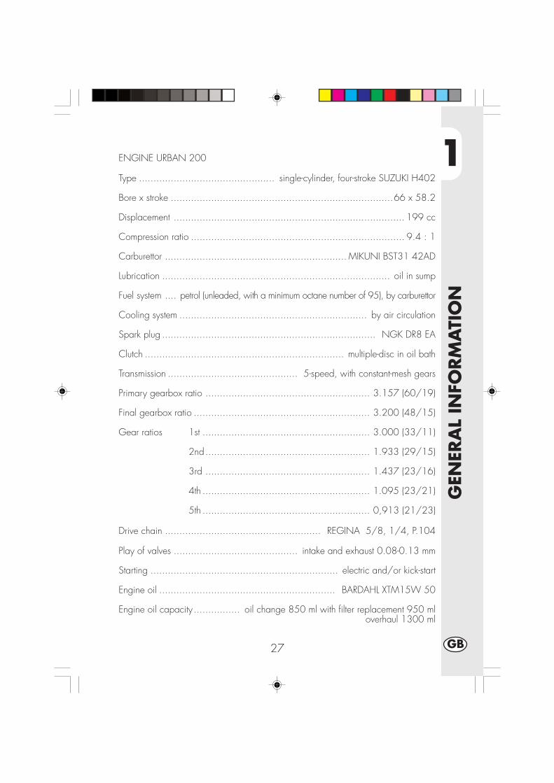
1
GEN
ERA
L IN
FORM
ATI
ON
27 GB
ENGINE URBAN 200
Type ............................................... single-cylinder, four-stroke SUZUKI H402
Bore x stroke .............................................................................66 x 58.2
Displacement ................................................................................ 199 cc
Compression ratio .......................................................................... 9.4 : 1
Carburettor ............................................................... MIKUNI BST31 42AD
Lubrication ............................................................................... oil in sump
Fuel system .... petrol (unleaded, with a minimum octane number of 95), by carburettor
Cooling system ................................................................. by air circulation
Spark plug .......................................................................... NGK DR8 EA
Clutch ..................................................................... multiple-disc in oil bath
Transmission ............................................. 5-speed, with constant-mesh gears
Primary gearbox ratio ......................................................... 3.157 (60/19)
Final gearbox ratio ............................................................. 3.200 (48/15)
Gear ratios 1st .......................................................... 3.000 (33/11)
2nd......................................................... 1.933 (29/15)
3rd ......................................................... 1.437 (23/16)
4th .......................................................... 1.095 (23/21)
5th .......................................................... 0,913 (21/23)
Drive chain ...................................................... REGINA 5/8, 1/4, P.104
Play of valves ........................................... intake and exhaust 0.08-0.13 mm
Starting ................................................................. electric and/or kick-start
Engine oil ............................................................. BARDAHL XTM15W 50
Engine oil capacity ................ oil change 850 ml with filter replacement 950 ml overhaul 1300 ml
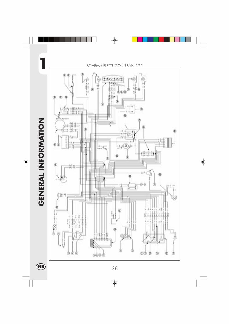
1
GEN
ERA
L IN
FORM
ATI
ON
28GB
SCHEMA ELETTRICO URBAN 125

1
GEN
ERA
L IN
FORM
ATI
ON
29 GB
WIRING DIAGRAM URBAN 1251) R.H. BLINKER (BULB 12V-10W)2) FRONT STOP PUSH BUTTON3) RIGHT CENTRAL UNIT4) ENGINE STOP5) STARTING BUTTON6) TELL TALE LAMP CENTRAL STAND7) NEUTRAL INDICATOR LIGHT8) HEADLIGHT TELL TALE LAMP9) TRAFFICATOR LIGHTS TELL TALE LAMP10) DISPLAY11) FRONT SENSOR WHEEL12) HEADLAMP (TWIN-LIGHT BULB 12V-5560W)13) SIDE LIGHT 12V-5W14) HORN BUTTON15) FLASH BUTTON16) HEADLIGHT SELECTOR17) TURN SIGNAL LAMPS SWITCH18) LEFT CENTRAL UNIT19) CLUTCH BUTTON20) AT COIL21) UNIT TURN SIGNAL LAMPS22) L.H. BLINKER (BULB 12V-10W)23) REGULATOR 12V24) CONDENSER25) STARTER MOTOR26) ENGINE CENTR.WEIGHT27) DIODE GR. 1A28) FUSE 15A29) REM. CONTROL SWITCH30) HERMETIC BATTERY 12V-9Ah31) L.H. BLINKER (BULB 12V-10W)32) PLATE ILLUMINATION (BULB 12V-5W)33) CENTR.WEIGHT34) POSITION35) STOP36) DIODE 1A37) TAIL LAMP (LED)38) R.H. BLINKER (BULB 12V-10W)39) REAR STOP PUSH BUTTON40) FUEL SENSOR41) SENSOR P.T.C.42) SENSOR STAND43) ENGINE CENTR.WEIGHT44) CONTACT, NEUTRAL SWITCH45) DIODE 1A46) PICK-UP47) ELECTRONIC CONTROL UNIT48) KEY OPERATED SWITCH49) HORN
Key to coloursBi = WhiteVe = GreenMa= BrawnVi = Purple
Bl = BlueNe = BlackGi = YellowRs = Red
Ar = OrangeAz = Sky-blueRo = PinKGr = Grey

1
GEN
ERA
L IN
FORM
ATI
ON
30GB
SCHEMA ELETTRICO URBAN 200

1
GEN
ERA
L IN
FORM
ATI
ON
31 GB
Key to coloursBi = WhiteVe = GreenMa= BrownVi = Purple
Bl = BlueNe = BlackGi = YellowRs = Red
Ar = OrangeAz = Sky-blueRo = PinkGr = Grey
WIRING DIAGRAM URBAN 1251) R.H. BLINKER (BULB 12V-10W)2) FRONT STOP PUSH BUTTON3) RIGHT CENTRAL UNIT4) ENGINE STOP5) STARTING BUTTON6) TELL TALE LAMP CENTRAL STAND7) NEUTRAL INDICATOR LIGHT8) HEADLIGHT TELL TALE LAMP9) TRAFFICATOR LIGHTS TELL TALE LAMP10) DISPLAY11) FRONT SENSOR WHEEL12) HEADLAMP (TWIN-LIGHT BULB 12V-5560W)13) SIDE LIGHT 12V-5W14) HORN BUTTON15) FLASH BUTTON16) HEADLIGHT SELECTOR17) TURN SIGNAL LAMPS SWITCH18) LEFT CENTRAL UNIT19) CLUTCH BUTTON20) L.H. BLINKER (BULB 12V-10W)21) UNIT TURN SIGNAL LAMPS22) AT COIL23) REGULATOR 12V24) DIODE GR. 1A25) FUSE 15A26) ENGINE CENTR.WEIGHT27) STARTER MOTOR28) CONDENSER 4700μ F-25V29) DIODE 6A30) REM. CONTROL SWITCH31) HERMETIC BATTERY32) L.H. BLINKER (BULB 12V-10W)33) PLATE ILLUMINATION (BULB 12V-5W34) CENTR.WEIGHT35) POSITION36) STOP37) Nº2 DIODE 1A38) TAIL LAMP (LED)39) R.H. BLINKER (BULB 12V-10W40) REAR STOP PUSH BUTTON41) FUEL SENSOR42) SENSOR P.T.C.43) SENSOR STAND44) ENGINE CENTR.WEIGHT45) CONTACT, NEUTRAL SWITCH46) PICK-UP47) ELECTRONIC CONTROL UNIT48) KEY OPERATED SWITCH49) HORN
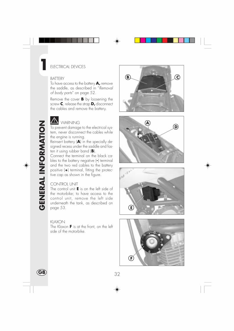
1
GEN
ERA
L IN
FORM
ATI
ON
32GB
ELECTRICAL DEVICES
BATTERYTo have access to the battery A, removethe saddle, as described in “Removalof body parts” on page 52.
Remove the cover B by loosening thescrew C, release the strap D, disconnectthe cables and remove the battery.
WARNINGTo prevent damage to the electrical sys-tem, never disconnect the cables whilethe engine is running.Reinsert battery (A) in the specially de-signed recess under the saddle and fas-ten it using rubber band (B).Connect the terminal on the black ca-bles to the battery negative (-) terminaland the two red cables to the batterypositive (+) terminal, fitting the protec-tive cap as shown in the figure.
CONTROL UNITThe control unit E is on the left side ofthe motorbike; to have access to thecontrol unit, remove the left sideunderneath the tank, as described onpage 53.
KLAXONThe Klaxon F is at the front, on the leftside of the motorbike.
AD
E
F
B C

1
GEN
ERA
L IN
FORM
ATI
ON
33 GB
FLICKERINGThe flickering system G is under the tank;to have access to it, remove the right sideunderneath the tank, as described onpage 53.
HV REEL – STARTER RELAY – STANDRELAY - FUSEThe reel H, the starter relay I, the standrelay L and the fuse M are centrallylocated on the left side of the motorbike.The left side contains:- The klaxon,- The indicators,- The instruments,- Engine ignition.
Notes:Any burnt fuse must be replaced with anequivalent one. If the new fuse burns outtoo, contact a BETAMOTOR licensedgarage.The fuse’s capacity is 15 Ampere.
WARNING:Never fit a fuse of a higher power or tryto ‘repair’ it; an improper repair coulddamage the whole electric system.
VOLTAGE REGULATORThe voltage regulator N is centrallylocated.
G
H
L
N
I
M

1
GEN
ERA
L IN
FORM
ATI
ON
34GB
A
AIS VALVEIt is called AIS valve and is an air inflowsystem that completes the combustion ofthat part of un-burnt hydrocarbons thatare the by-product of the thermodynamiccycle.
To have access to the valve A, removethe right guard under the tank, asdescribed on page 52

2
OPER
ATI
ON
35 GB
CONTENTS
CHAPTER 2 OPERATION
Checks and maintenance before and after off-road use
Recommended lubricants and fluids
Running-in
Starting the engine
Shutting off the engine
Refuelling

2
OPER
ATI
ON
36GB
CHECKS AND MAINTENANCE OPERATIONS BEFORE AND AFTER OFF-ROADUSE
To avoid trouble during operation, it is advisable to perform a few checks andmaintenance operations before and after riding. In addition to making your vehiclesafer, a few minutes spent carrying out these operations will enable you to save timeand money.Follow these steps:
TYRES Check the inflating pressures, the general condition, and thetread depth (see page 9).
SPOKES Check the tensioning.NUTS AND BOLTS Check the tightening of all nuts and bolts.DRIVE CHAIN Check the tension (play = 20 mm) and if necessary grease.AIR FILTER Clean the filter and wet it with oil (see page 48).
NoteCheck for the presence of the vehicle identification papers.In cold weather, it is advisable to warm up the engine by letting it idle for a fewmoments before starting off.The vehicle needs to be carefully washed every time it is used over rough ground.
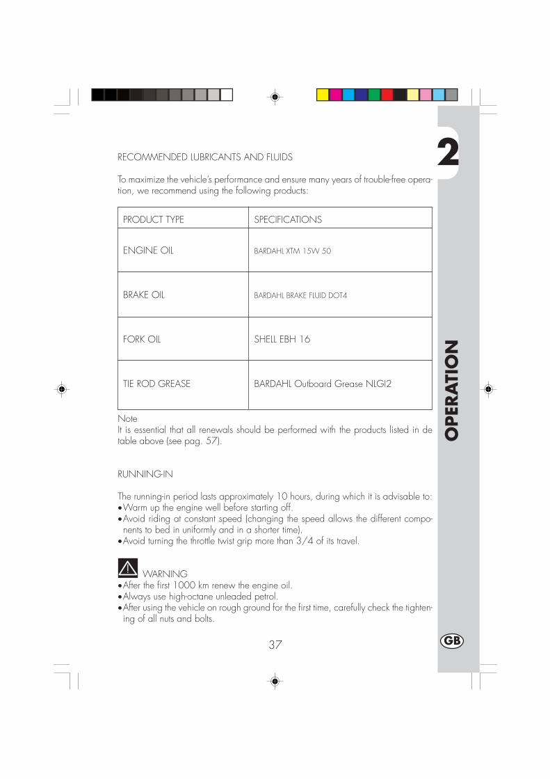
2
OPER
ATI
ON
37 GB
PRODUCT TYPE SPECIFICATIONS
ENGINE OIL BARDAHL XTM 15W 50
BRAKE OIL BARDAHL BRAKE FLUID DOT4
FORK OIL SHELL EBH 16
TIE ROD GREASE BARDAHL Outboard Grease NLGI2
RECOMMENDED LUBRICANTS AND FLUIDS
To maximize the vehicle’s performance and ensure many years of trouble-free opera-tion, we recommend using the following products:
NoteIt is essential that all renewals should be performed with the products listed in detable above (see pag. 57).
RUNNING-IN
The running-in period lasts approximately 10 hours, during which it is advisable to:•Warm up the engine well before starting off.•Avoid riding at constant speed (changing the speed allows the different compo-nents to bed in uniformly and in a shorter time).
•Avoid turning the throttle twist grip more than 3/4 of its travel.
WARNING•After the first 1000 km renew the engine oil.•Always use high-octane unleaded petrol.•After using the vehicle on rough ground for the first time, carefully check the tighten-ing of all nuts and bolts.
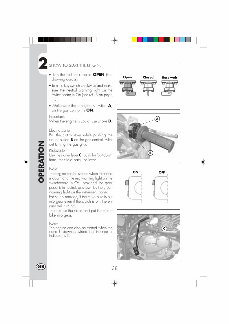
2
OPER
ATI
ON
38GB
SHOW TO START THE ENGINE
• Turn the fuel tank tap to OPEN (seedrawing across).
• Turn the key switch clockwise and makesure the neutral warning light on theswitchboard is On (see ref. 3 on page13).
• Make sure the emergency switch A,on the gas control, is ON.
Important:When the engine is could, use choke D.
Electric starterPull the clutch lever while pushing thestarter button B on the gas control, with-out turning the gas grip.
Kick-starterUse the starter lever C; push the foot downhard, then fold back the lever.
Note:The engine can be started when the standis down and the red warning light on theswitchboard is On, provided the gearpedal is in neutral, as shown by the greenwarning light on the instrument panel.For safety reasons, if the motorbike is putinto gear even if the clutch is on, the en-gine will turn off.Then, close the stand and put the motor-bike into gear.
Note:The engine can also be started when thestand is down provided that the neutralindicator is lit.
A
ON OFF
B
C
Open Closed Reservoir
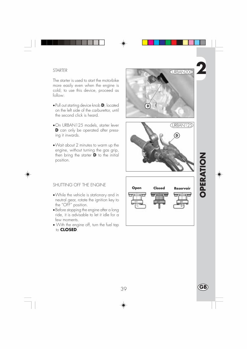
2
OPER
ATI
ON
39 GB
STARTER
The starter is used to start the motorbikemore easily even when the engine iscold; to use this device, proceed asfollow:
•Pull out starting device knob D, locatedon the left side of the carburettor, untilthe second click is heard.
•On URBAN125 models, starter leverD can only be operated after press-ing it inwards.
•Wait about 2 minutes to warm up theengine, without turning the gas grip,then bring the starter D to the initialposition.
SHUTTING OFF THE ENGINE
•While the vehicle is stationary and inneutral gear, rotate the ignition key tothe “OFF” position.
•Before stopping the engine after a longride, it is advisable to let it idle for afew moments.
• With the engine off, turn the fuel tapto CLOSED.
Open Closed Reservoir
D
D
URBAN125
URBAN200

2
OPER
ATI
ON
40GB
REFUELLING
•Switch off the engine.•Remove cap A.
NoteThe fuel tank capacity is approximately6 litres, including 1 litres reserve.
WARNING:Gasoline is extremely flammable.
Immediately remove any leak of gaso-line from the body or any other part.
Before refuelling, turn off the engine.
Do not let the gasoline leak out of thetank whi le refuelling.
Do not get close to the filler neck withnaked flames or lighted cigarettes.
Do not inhale harmful fuels.
A

3
CH
ECK
S A
ND
MA
INTE
NA
NCE
41 GB
CONTENTS
CHAPTER 3 CHECKS AND MAINTENANCE
Engine oil and oil filter
Fume collecting tube
Brake pump oil - Bleeding the brakes
Fork oil
Air filter
Spark plug
Front and rear brakes
Battery
Removing the bodywork
Notes for trial use
Cleaning and checking the vehicle
Scheduled maintenance
Prolonged inactivity

3
CH
ECK
S A
ND
MA
INTE
NA
NCE
42GB
ENGINE OIL AND OIL FILTER URBAN 200
CheckKeep the vehicle in an upright position.Check the oil level through oil level sightA when the engine is cold. The oil levelmust never fall below the sight. If neces-sary, top up after removing filler cap B.
Topping upOnly top up after checking the max levelshown on sight A.
RenewalAlways renew the oil when the engine ishot. To avoid burns, take care not to touchthe engine and the oil.•Replace the oil when replacing the oilfilter.
•Put the vehicle on its stand.• Put a container under the engine, rightunder the drain plug D.
•Unscrew filler plug B and drain plug D.•Drain all the oil from the crankcase.•Close plug D.•Remove the oil filter cover after unscrew-ing the three nuts C.
•Remove the oil filter and replace it witha new one.
•Apply a thin film of engine oil to thefilter cover O-ring before insertion.
•Apply a film of engine oil over the filtercover O-ring before fitting it.
B
A
C
D

3
CH
ECK
S A
ND
MA
INTE
NA
NCE
43 GB
•Fit the oil filter cover after fitting the springand the O-ring, and then tighten the threefastening nuts C.
•Fill in with the right amount of oil:
- Oil replacement 850 ml- With filter replacement 950 ml- Overhaul 1300 ml
•Close the inlet plug B again.dle for afew minutes.
•Turn off the engine and wait for aboutone minute, then check the level and topup if needed, without exceeding the maxlevel shown on the window A.
NoteRenew the oil after the first 1,000 km.Subsequent renewals should be every5,000 km 15 months, (refer to the tableon page 57). Always use the lubricantsshown on page 37.The oil filter should be replaced for the firsttime when the oil is first renewed, and sub-sequently every 10,000 km (30 months).
IMPORTANTDispose of used oil in compliance with theregulations in force.

3
CH
ECK
S A
ND
MA
INTE
NA
NCE
44GB
ENGINE OIL AND OIL FILTER URBAN125
CheckKeep the vehicle in an upright position.The engine is cold, check for the pres-ence of oil.
Topping upTo restore the level, remove cap A andtop up.
RenewalAlways renew the oil when the engine ishot. To avoid burns, take care not to touchthe engine and the oil.•Put the vehicle on its stand.•Extract the two screws D and fasteningE, and then remove protection C.
•Place a container under the engine.•Unscrew filler plug A and drain plug B.•Drain all the oil from the crankcase.•Close plug B.•Pour in 1000 cc of fresh oil.•Screw on filler cap A again.
WARNINGHot oil can cause severe burns.
Note:the URBANI25 engine contains the rotaryoil filter, which is mounted on the clutchside of the drive shaft. To replace it,contact a licensed Betamotor dealer.Note:Renew the engine oil after the first 500km. For the renewal intervals, refer to thetable on page 57. Only use the lubri-cants recommended on page 37.
IMPORTANTDispose of used oil in compliance withthe regulations in force.
A
B

3
CH
ECK
S A
ND
MA
INTE
NA
NCE
45 GB
FUME COLLECTING PIPEFume collecting tube A is located on the leftside of the vehicle next to the shock absorber.It comes out of the lower part of the Intakesleeve and is designed to collect the fumesproduced by the engine oil. It is designed tocollect the fumes produced by the engine oil.Should any oil be found in the tube, removethe cap at the lower end of the tube and drainthe oil, or the mixture of oil and petrol, into asuitable container. Disposal is to be made ac-cording to the regulations in force.NoteEmpty the fume collecting tube every 3,000 km.
IMPORTANTDispose of used oil in compliance with theregulations in force.
BRAKE PUMP OIL - BLEEDING THE BRAKESFront brakeCheck that oil is present by looking through oillevel sight B. The minimum oil level shouldnever be lower than the mark on sight B. Torestore the oil level, loosen the two screws C,lift cover D and pour in fresh oil.Rear brakeCheck the oil level through the level lightE. The min oil level must never drop belowthe mark shown by the warning light E.To fill up, loosen the two screws F, lift theplug G and pour in the oil.
WARNINGA spongy feel of the brake lever may bedue to an air bubble in the braking sys-tem. Immediately contact an authorizedworkshop. In this case, bleed any air outof the braking circuit.NoteFor information on oil renewals, refer tothe table on page 57. Use the recom-mended lubricants shown on page 37.
A
D
C
B
F
EG
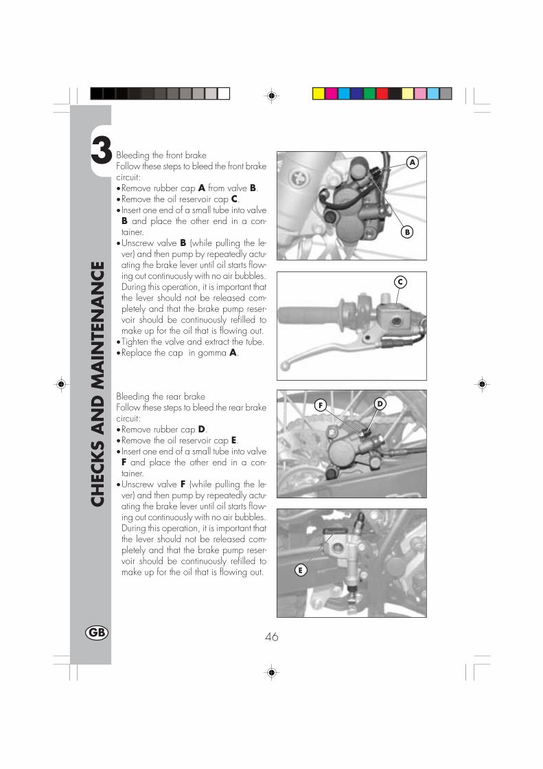
3
CH
ECK
S A
ND
MA
INTE
NA
NCE
46GB
Bleeding the front brakeFollow these steps to bleed the front brakecircuit:•Remove rubber cap A from valve B.•Remove the oil reservoir cap C.• Insert one end of a small tube into valveB and place the other end in a con-tainer.
•Unscrew valve B (while pulling the le-ver) and then pump by repeatedly actu-ating the brake lever until oil starts flow-ing out continuously with no air bubbles.During this operation, it is important thatthe lever should not be released com-pletely and that the brake pump reser-voir should be continuously refilled tomake up for the oil that is flowing out.
•Tighten the valve and extract the tube.•Replace the cap in gomma A.
Bleeding the rear brakeFollow these steps to bleed the rear brakecircuit:•Remove rubber cap D.•Remove the oil reservoir cap E.• Insert one end of a small tube into valveF and place the other end in a con-tainer.
•Unscrew valve F (while pulling the le-ver) and then pump by repeatedly actu-ating the brake lever until oil starts flow-ing out continuously with no air bubbles.During this operation, it is important thatthe lever should not be released com-pletely and that the brake pump reser-voir should be continuously refilled tomake up for the oil that is flowing out.
DF
A
B
C
E

3
CH
ECK
S A
ND
MA
INTE
NA
NCE
47 GB
FORK OIL
Right-hand rodsThe procedure for changing the oil in theforks is provided only for information. Werecommend having the operation per-formed by a BETAMOTOR authorizedworkshop.Follow these steps to renew the oil:1) Loosen rod clamping screw A.
2) Remove the lower plug (Allen screwin the legging) and upper plug B.
3) Let all the oil drain from the rod.
4) Fit and tighten the legging lower plug.
5) Pour in fresh oil of the type shown inthe table on page 37.
6) Fit and tighten upper plug B.
7) Retighten rod clamping screw A.
Note:The oil change procedure applies to boththe left and the right fork legs.
A
B

3
CH
ECK
S A
ND
MA
INTE
NA
NCE
48GB
AIR FILTER
To have access to the filter unit A, removethe saddle, as described in “Removal ofbody parts” on page 52.
• Remove the cover B by loosening thescrew C.
• Lift the battery holder, as shown in thefigure,
• Release the filter holder D.• Remove the filter unit A.• Pull out the holder D and take out thesponge filter.• Wash it with soap and water.• Dry the filter.•Wet the filter with filter oil. Remove any ex-
cess lubricant to prevent it from dripping.• If necessary, also clean the inside of the
filter casing.• Refit the parts, making sure of the seal of
the rubber gasket.
Note:If the filter is very dirty, first wash it with aspecial detergent and then with water andshampoo.If the filter is damaged, immediately re-place it.Clean the filter every time the vehicle isused off road.
WARNING:After working on the filter, ensure that noth-ing is left inside the filter casing.
D
A
B C
DA

3
CH
ECK
S A
ND
MA
INTE
NA
NCE
49 GB
SPARK PLUG
To avoid burns, put on pro-tective gloves before per-forming the operation.
Keeping the spark plug in good condi-tion makes for reduced consumption andoptimum engine performance.It is advisable to remove the spark plugwhen the engine is hot (and naturally off)because the carbon formation and thecolour of the insulator provide importantinformation on carburetion, lubrication,and the general condition of the engine.If the insulator appears white, the mixtureis probably too lean; conversely, a greeninsulator denotes a rich mixture. The mix-ture is correct when the insulator is tan col-oured.To carry out the check, simply removethe current cap and then unscrew thespark plug using the spanner provided.Carefully clean the electrodes using awire brush. Blow the spark plug with com-pressed air to prevent any residues fromgetting into the engine.Measure the spark gap with a thicknessgauge. The gap should be 0.6-0.7 mm.If the gap is not as specified, restore theproper gap by bending the earth elec-trode.
Check that the insulator is not crackedand that the electrodes are not corroded,in which case the spark plug should beimmediately replaced.
Conduct the check by referring to the table on page 57.
Note:Lubricate the spark plug thread, and then(when the engine is cold) screw in thespark plug by hand to its abutting end.Finally tighten the spark plug with thespanner.
Note:•Always use spark plugs:URBAN 200 = NGK DR8 EAURBAN 125 = NGK CR7 HSA
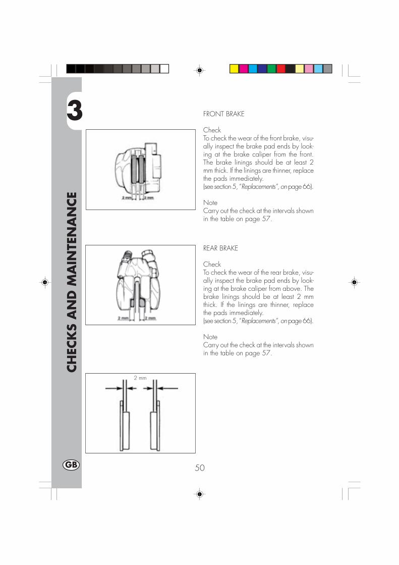
3
CH
ECK
S A
ND
MA
INTE
NA
NCE
50GB
FRONT BRAKE
CheckTo check the wear of the front brake, visu-ally inspect the brake pad ends by look-ing at the brake caliper from the front.The brake linings should be at least 2mm thick. If the linings are thinner, replacethe pads immediately.(see section 5, “Replacements”, on page 66).
NoteCarry out the check at the intervals shownin the table on page 57.
REAR BRAKE
CheckTo check the wear of the rear brake, visu-ally inspect the brake pad ends by look-ing at the brake caliper from above. Thebrake linings should be at least 2 mmthick. If the linings are thinner, replacethe pads immediately.(see section 5, “Replacements”, on page 66).
NoteCarry out the check at the intervals shownin the table on page 57.
2 mm
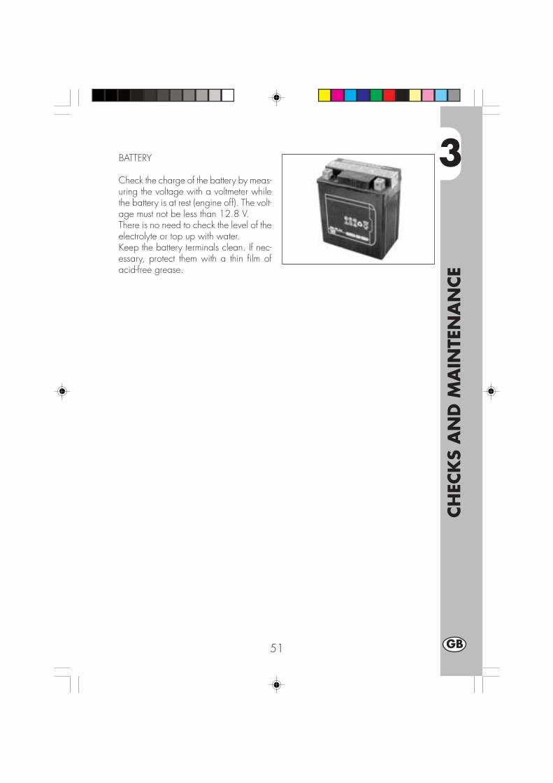
3
CH
ECK
S A
ND
MA
INTE
NA
NCE
51 GB
BATTERY
Check the charge of the battery by meas-uring the voltage with a voltmeter whilethe battery is at rest (engine off). The volt-age must not be less than 12.8 V.There is no need to check the level of theelectrolyte or top up with water.Keep the battery terminals clean. If nec-essary, protect them with a thin film ofacid-free grease.

3
CH
ECK
S A
ND
MA
INTE
NA
NCE
52GB
HOW TO REMOVE BODY PARTS
Some parts of the body may have to beremoved for easier inspections or main-tenance.
WARNING:If these parts are improperly reassembled,they might suddenly come off while driv-ing, and the driver might lose control ofthe motorbike.
How to remove the saddleTo remove the saddle, just remove thetwo screws A, the clamp B and the clampC underneath the saddle.
Note:When removing the saddle the fenderwill come off too.To separate the two parts, remove thethree screws D.
How to remove the tank coversTo remove the tank covers E, proceed asfollows:
• Loosen the screws F on the tank.• Loosen the two clamps G, in the front
of the motorbike.• Remove the tank cover E.
F
E
G
A
B
C
D

3
CH
ECK
S A
ND
MA
INTE
NA
NCE
53 GB
How to remove the fuel tankRemove the saddle, then loosen the screw Hwhich secures the tank to the frame, removethe pipe of the fuel tap and take off the tankby pulling it out of the back.
How to remove the side framesTo remove the two side frames L underthe tank on both sides of the motorbike,just remove the two screws I.
How to remove the front lightholderRemove the lamp screws N, disconnectthe lamp wires, then remove the twoscrews M which secure the lamp-hold-ing unit.
H
L
I
N
M
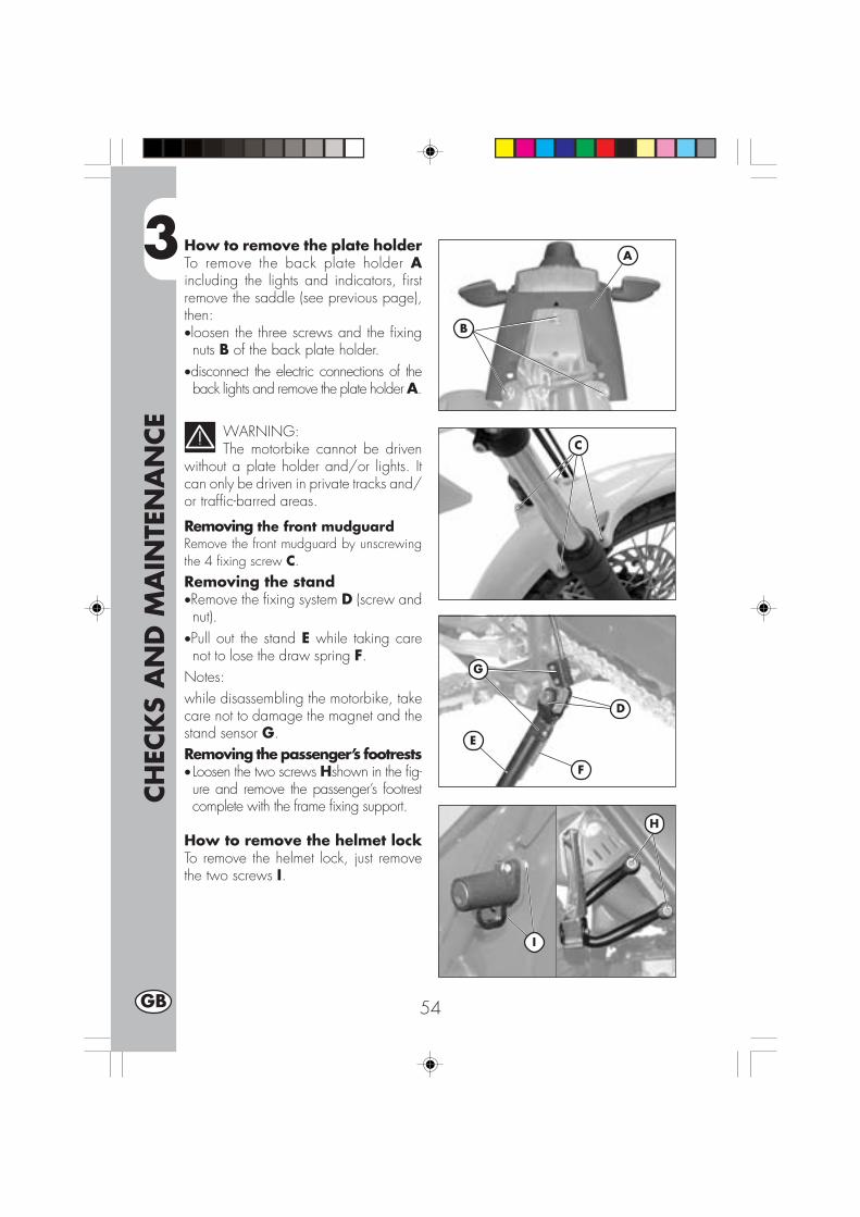
3
CH
ECK
S A
ND
MA
INTE
NA
NCE
54GB
A
B
E
D
F
G
H
I
How to remove the plate holderTo remove the back plate holder Aincluding the lights and indicators, firstremove the saddle (see previous page),then:•loosen the three screws and the fixingnuts B of the back plate holder.
•disconnect the electric connections of theback lights and remove the plate holder A.
WARNING:The motorbike cannot be driven
without a plate holder and/or lights. Itcan only be driven in private tracks and/or traffic-barred areas.
Removing the front mudguardRemove the front mudguard by unscrewingthe 4 fixing screw C.
Removing the stand•Remove the fixing system D (screw andnut).
•Pull out the stand E while taking carenot to lose the draw spring F.
Notes:while disassembling the motorbike, takecare not to damage the magnet and thestand sensor G.Removing the passenger’s footrests• Loosen the two screws Hshown in the fig-ure and remove the passenger’s footrestcomplete with the frame fixing support.
How to remove the helmet lockTo remove the helmet lock, just removethe two screws I.
C
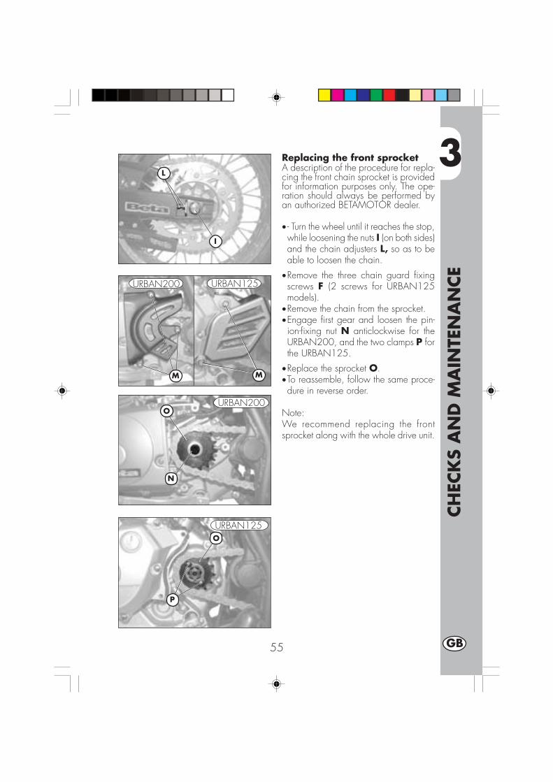
3
CH
ECK
S A
ND
MA
INTE
NA
NCE
55 GB
I
M
O
N
L
M
P
O
URBAN200 URBAN125
URBAN200
URBAN125
Replacing the front sprocketA description of the procedure for repla-cing the front chain sprocket is providedfor information purposes only. The ope-ration should always be performed byan authorized BETAMOTOR dealer.
• - Turn the wheel until it reaches the stop,while loosening the nuts I (on both sides)and the chain adjusters L, so as to beable to loosen the chain.
•Remove the three chain guard fixingscrews F (2 screws for URBAN125models).
•Remove the chain from the sprocket.•Engage first gear and loosen the pin-ion-fixing nut N anticlockwise for theURBAN200, and the two clamps P forthe URBAN125.
•Replace the sprocket O.•To reassemble, follow the same proce-dure in reverse order.
Note:We recommend replacing the frontsprocket along with the whole drive unit.
3
CH
ECK
S A
ND
MA
INTE
NA
NCE
56GB
CLEANING AND CHECKING THE VEHICLE
Use a low-pressure water jet to soften the dirt and mud accumulated on the paintwork,then remove them with a soft bodywork sponge soaked in water and shampoo (2-4 percent shampoo in water). Rinse generously with water and wipe dry withchamois leather. For the outside of the engine use a brush soaked in petroleum andclean rags. Petroleum damages the paintwork. Always wash the vehicle beforewaxing it with silicon waxes.
Detergents pollute the waters. Always wash the vehicle in areas equippedfor the collection and purification of the washing liquids.
Never wash the vehicle in the sun, particularly during the summer when thebodywork is hot. The shampoo would dry before being rinsed off and causedamage to the paintwork. Do not clean the plastic surfaces with clothssoaked in petrol or naphtha as they would lose their shine and mechanicalproperties.
Water jets can damage the instruments; do not direct the jet towards theelectric parts, especially the LCD display.
CHECKS AFTER CLEANING
After cleaning the motorcycle, it is advisable to:
•Clean the air filter (refer to the procedure described on page 48).•Grease the chain.
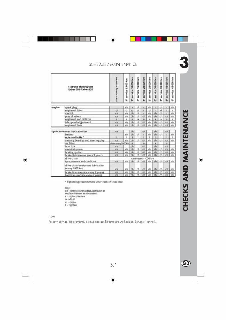
3
CH
ECK
S A
ND
MA
INTE
NA
NCE
57 GB
SCHEDULED MAINTENANCE
Note
For any service requirements, please contact Betamotor’s Authorized Service Network.

3
CH
ECK
S A
ND
MA
INTE
NA
NCE
58GB
AFTER PROLONGED INACTIVITY
•Reinstall the battery.•Restore the tyre inflating pressures.•Check the tightening of all the screws having an important mechanical function.
NotePeriodically check the tightening of the screws.
•Start the vehicle for the first time by means of the kick-start.
PROLONGED INACTIVITY
A few simple operations should be performed to keep the vehicle in good conditionwhenever it is to remain inactive for a long period (e.g. during the winter):
•Thoroughly clean the vehicle.•Reduce the tyre pressures by approxi-mately 30 percent, and if possible raisethe tyres off the ground.
•Remove the spark plug and pour a fewdrops of engine oil into the spark plughole. Make the engine turn a few timesby operating the kick-start (where avail-able) and then replace the spark plug.
•Cover the unpainted parts, exceptingthe brakes and the rubber parts, with afilm of oil or spray silicone.
•Remove the battery and keep it in a dryplace. Recharge the battery once amonth.
•Protect the vehicle with a dust cover.•Drain the carburettor float chamber byloosening screw A. The fuel drainedfrom the chamber through a suitablepipe must be collected in a containerand poured into the fuel tank. Do notdispose of the fuel in the environment.
•Retighten the screw.
A
A
URBAN200
URBAN125

4
AD
JUST
MEN
TS
59 GB
CONTENTS
CHAPTER 4 ADJUSTMENTS
Adjusting the brakes
Adjusting the clutch
Adjusting the slow running
Adjusting the throttle play
Checking and adjusting the steering play
Tensioning the chain
Adjusting the headlight
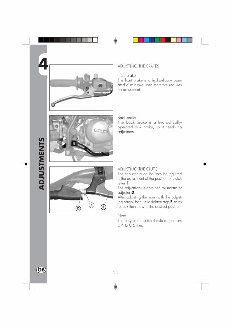
4
AD
JUST
MEN
TS
60GB
ADJUSTING THE BRAKES
Front brakeThe front brake is a hydraulically oper-ated disc brake, and therefore requiresno adjustment.
Back brakeThe back brake is a hydraulically-operated disk brake, so it needs noadjustment.
ADJUSTING THE CLUTCHThe only operation that may be requiredis the adjustment of the position of clutchlever E.The adjustment is obtained by means ofadjuster D.After adjusting the lever with the adjust-ing screw, be sure to tighten stop F so asto lock the screw in the desired position.
NoteThe play of the clutch should range from0.4 to 0.6 mm.
FD E
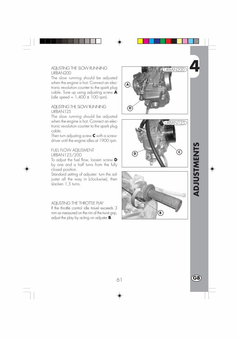
4
AD
JUST
MEN
TS
61 GB
ADJUSTING THE SLOW RUNNINGURBAN200The slow running should be adjustedwhen the engine is hot. Connect an elec-tronic revolution counter to the spark plugcable. Tune up using adjusting screw A(idle speed = 1,400 ± 100 rpm).
ADJUSTING THE SLOW RUNNINGURBAN125The slow running should be adjustedwhen the engine is hot. Connect an elec-tronic revolution counter to the spark plugcable.Then turn adjusting screw C with a screw-driver until the engine idles at 1900 rpm.
FUEL FLOW ADJUSMENTURBAN125/200To adjust the fuel flow, loosen screw Dby one and a half turns from the fullyclosed position.Standard setting of adjuster: turn the ad-juster all the way in (clockwise), thenslacken 1,5 turns.
ADJUSTING THE THROTTLE PLAYIf the throttle control idle travel exceeds 3mm as measured on the rim of the twist grip,adjust the play by acting on adjuster B.
B
A
CD
URBAN200
URBAN125
D

4
AD
JUST
MEN
TS
62GB
CHECKING AND ADJUSTING THESTEERING PLAY
Periodically check the play of the steer-ing head tube by moving the forks back-wards and forwards as shown in thefigure. If any play is felt, carry out theadjustment by following these steps:•Unscrew the four screws A.•Pull out handlebar B, paying specialattention to clevises C.
• Loosen nut D.• Loosen the two screws F.•Reduce the play by turning ring E.To refit the parts, follow the reverse pro-cedure.
NoteProper adjustment must leave no playand cause no stiffness, and allow thesteering to rotate smoothly. Check thefitting direction of the clevises as it canalter the geometry of the handlebar.
B
D
E C
A
F F
Note:The operration should always be per-formed by an authorized Betamotordealer.

4
AD
JUST
MEN
TS
63 GB
TENSIONING THE CHAIN
To ensure the drive chain a longer life, itis advisable to periodically check its ten-sion.Always maintain the chain clean and lu-bricated.If the chain play exceeds 20 mm, ten-sion the chain by following these steps:
•Loosen the nuts A on both branche ofthe big fork.
•Loosen the nut C on both branches ofthe big fork.
•Turn the nut B until the chain is properlystretched.
•Do the same with the nut B, which is onthe other branch of the big fork, untilthe wheel is perfectly aligned.
•Tighten the nuts B and A on bothbranches of the fork.
20 mm
B
C A

4
AD
JUST
MEN
TS
64GB
ADJUSTING THE HEADLIGHT
•The headlight beam is adjusted manually after loosening the screws on either sideof the headlight with an Allen key.
•Periodically check the direction of the beam. The beam can only be adjustedvertically.
•Place the vehicle on level ground (but not on the stand) 10 metres from a verticalwall.
•Measure the height of the headlight centre above the ground and then draw across on the wall at 9/10 of the height of the headlight centre.
•Turn on the low beam, get on the motorbike and check that the headlight beam onthe wall is slightly lower than the cross drawn previously.
9/10
h
10 m
h
AA
5
REP
LACEM
ENTS
65 GB
CONTENTS
CHAPTER 5 REPLACEMENTS
Replacing the brake pads
Replacing the headlight bulb
Replacing the rear light bulb
Replacing the turn indicator bulbs
Bulbs characteristics
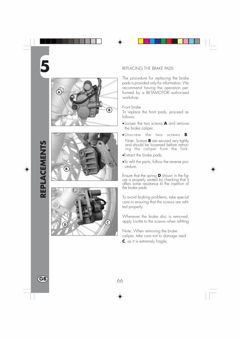
5
REP
LACEM
ENTS
66GB
REPLACING THE BRAKE PADS
The procedure for replacing the brakepads is provided only for information. Werecommend having the operation per-formed by a BETAMOTOR authorizedworkshop.
Front brakeTo replace the front pads, proceed asfollows:
• Loosen the two screws A and removethe brake caliper.
•Unscrew the two screws B.Note: Screws B are secured very tightlyand should be loosened before remov-ing the caliper from the fork.
•Extract the brake pads.
•To refit the parts, follow the reverse pro-cedure.
Ensure that the spring D shown in the fig-ure is properly seated by checking that itoffers some resistance to the insertion ofthe brake pads.
To avoid braking problems, take specialcare in ensuring that the screws are refit-ted properly.
Whenever the brake disc is removed,apply Loctite to the screws when refitting
Note: When removing the brakecaliper, take care not to damage reedC, as it is extremely fragile.
CD
A
B
B
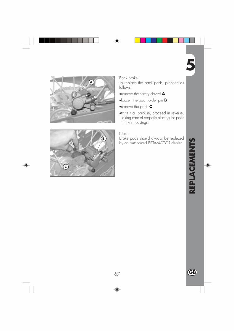
5
REP
LACEM
ENTS
67 GB
Back brakeTo replace the back pads, proceed asfollows:
•remove the safety dowel A
•loosen the pad holder pin B•remove the pads C.
•to fit it all back in, proceed in reverse,taking care of properly placing the padsin their housings.
Note:Brake pads should always be replecedby an authorized BETAMOTOR dealer.
A
B
C
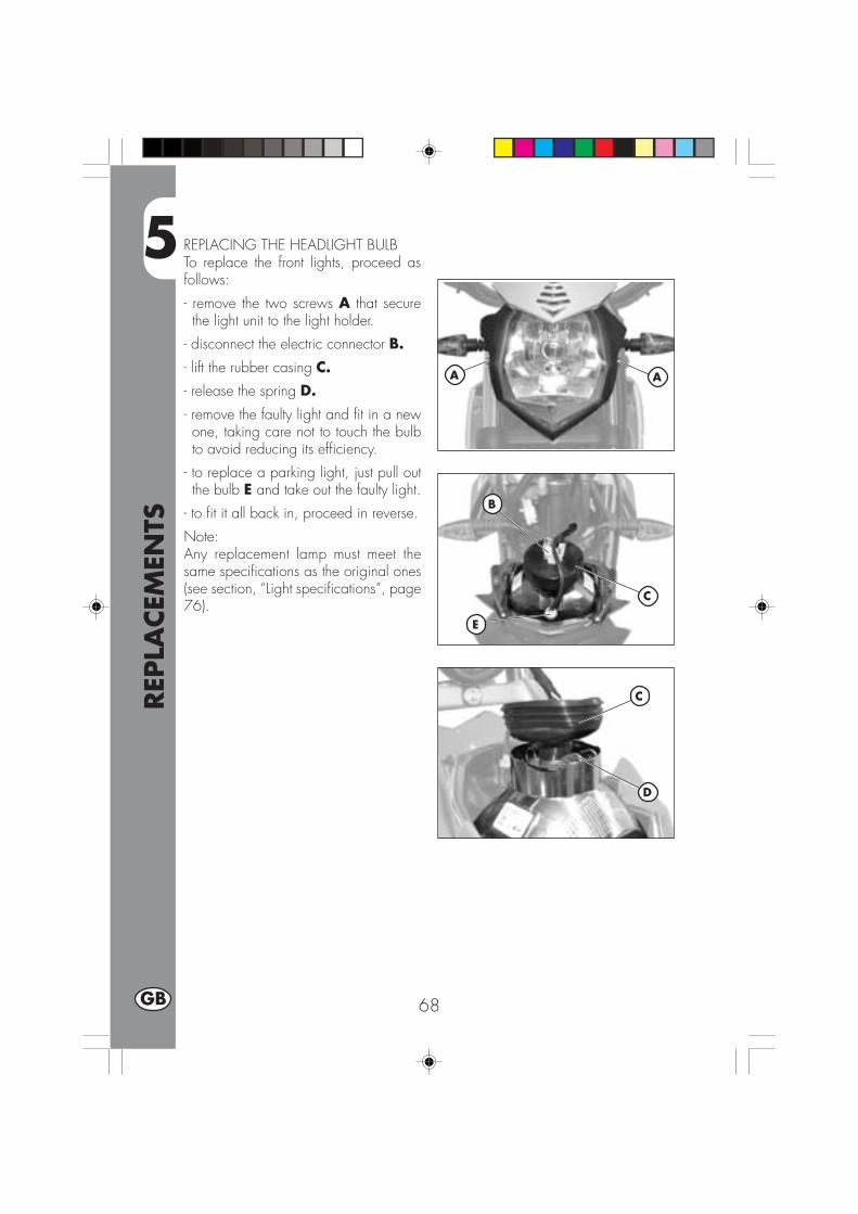
5
REP
LACEM
ENTS
68GB
REPLACING THE HEADLIGHT BULBTo replace the front lights, proceed asfollows:
- remove the two screws A that securethe light unit to the light holder.
- disconnect the electric connector B.
- lift the rubber casing C.- release the spring D.
- remove the faulty light and fit in a newone, taking care not to touch the bulbto avoid reducing its efficiency.
- to replace a parking light, just pull outthe bulb E and take out the faulty light.
- to fit it all back in, proceed in reverse.
Note:Any replacement lamp must meet thesame specifications as the original ones(see section, “Light specifications”, page76).
B
C
C
D
E
AA

5
REP
LACEM
ENTS
69 GB
REPLACING THE TURN INDICATORBULBS
To replace the plate number light,proceed as follows:
• Loosen the screw C.• Remove the transparent screen D.• Pull the faulty light out of the bulb andreplace with a new one.
• To fit it all back in, proceed in reverse.
Note:Any replacement lamp must meet thesame specifications as the original ones(see section, “Light specifications”, page76).
REPLACING THE REAR LIGHT BULB
To replace the back light unit A, proceedas follows:
• Remove the plate holder as describedin the section, “Removal of body parts”on page 60.
• Disconnect all electric connections.
• Loosen the two screws B under the fen-der.
• Pull out the faulty light unit A and replaceit with a new one.
• To fit it all back in, proceed in reverse.
Note:Any replacement lamp must meet thesame specifications as the original ones(see section, “Light specifications”, page76).
A
B
CD

5
REP
LACEM
ENTS
70GB
REPLACING THE TURN INDICATORBULBSTo replace the indicator lights, proceedas follows:
•Loosen screw A and remove the lens.
•Remove the faulty light and replace witha new one.
Note:Any replacement lamp must meet thesame specifications as the original ones(see Table below).
A
A
Headlamp bulb 12V-55/60WPosition bulb 12V-5WTrafficator lights bulbFront/Rear
12V-6W
Taillight/stop bulb LEDNumber plate light 12V-5W
BULBS CHARACTERISTICS

6
TRO
UBLE
SHO
OTI
NG
71 GB
CONTENTS
CHARTER 6 TROUBLESHOOTING
INDEX

6
TRO
UBLE
SHO
OTI
NG
72GB
PROBLEM CAUSE
Engine does not start
REMEDY
- Fuel system clogged (fuel lines,fuel tank, fuel cock).
- Air filter dirty.
- No current supplied to sparkplug.
- Engine flooded.
Clean the system.
Proceed as described on page 48.
Clean or replace the spark plug. If theproblem persists, contact aBETAMOTOR dealer.
Open the throttle wide and try startingthe engine for a few moments. If thisdoes not solve the problem, remove thespark plug and dry it.
Engine misfires - Spark gap wrongly adjusted.
- Spark plug dirty.
- Spark advance excessive.
- Carbon formation in cylinder oron spark plug.
Restore the spark gap.
Clean or replace the spark plug.
Engine knocks Check the ignition timing.
Contact a BETAMOTOR dealer.
Engine overheats andloses power
- Silencer partly clogged.
- Exhaust port clogged.
- Ignition delayed.
Contact a BETAMOTOR dealer.
Contact a BETAMOTOR dealer.
Check the timing.
Front braking poor - Brake pads worn.
- Air or humidity in the hydrauliccircuit.
- Brake pads worn.
- Air or humidity in the hydrauliccircuit.
Follow the procedure described onpage 66.
Follow the procedure described onpage 46.
Follow the procedure described onpage 66.
Follow the procedure described onpage 46.
Rear braking poor

IND
EX
73 GB
Air filter ............................................................................................. 48
Brake pump oil ................................................................................... 45Brakes, adjustment .............................................................................. 60Brakes, bleeding ................................................................................. 45Brake pad check and replacement ......................................................... 66Bulbs, replacement .............................................................................. 68
Chain, tensioning ................................................................................ 63Checks after cleaning .......................................................................... 56Checks and maintenance before and after off-road use .............................. 36Clutch, adjustment ............................................................................... 60
Engine oil, check and renewal URBAN200 ............................................. 42Engine oil, check and renewal URBAN125 .............................................. 44
Fork oil .............................................................................................. 47
Helmet lock ........................................................................................ 12
Ignition switch/Steering lock ................................................................. 12Instrument panel and controls .................................................................. 13LCD ................................................................................................... 14
Keys ................................................................................................. 12
Recommended lubricants and fluids ........................................................ 37Refuelling........................................................................................... 40Running-in .......................................................................................... 37
Scheduled maintenance ....................................................................... 57Slow running, adjustment ...................................................................... 61Spark plug ......................................................................................... 49Specifications ..................................................................................... 24Starting ............................................................................................. 38Steering, check and adjustment ............................................................. 62
Throttle play, adjustment ....................................................................... 61Troubleshooting................................................................................... 71
Vehicle identification data ....................................................................... 8
Wiring diagrams URBAN125 ............................................................... 28Wiring diagrams URBAN200 ................................................................ 30


1 F
URBAN 125/200 cc
Merci de votre confiance et bon divertissement. Ce livret vousdonnera les informations nécessaires pour une utilisation correcteet un bon entretien de votre moto.
Les informations et les caractéristiques indiquées dans ce manuel n’engagentpas BETAMOTOR S.p.A. qui se réserve le droit d’apporter des modifica-tions et des améliorations à ses modèles à tout moment et sans préavis.
2F
AVERTISSEMENT
Il est recommandé, au bout de la première ou de la secondeheure d’utilisation en tout-terrain, de contrôler tous les serragesavec une attention particulière pour:
• Couronne• Supports de cale-pieds• Étrier de frein avant• pinza freno posteriore• porte-plaque• cavalier pour fixage guidon• Support de garde-boue• Boulonnerie moteur• Boulonnerie amortisseur.• Rayons roue• Cadre arrière• Carenages
AVERTISSEMENT
En cas d’intervention à effectuer sur la moto, s’adresser au ré-seau d’assistance agréé Betamotor.

TABLE
DES
MA
TIÈR
ES
3 F
Conseils d’utilisation ............................................................................... 5Conduite écologique .............................................................................. 5Conduire en sécurité ............................................................................... 6
CHAP. 1 GÉNÉRALITÉS .............................................................. 7Données d’identification du véhicule .......................................................... 8Equipement ........................................................................................... 8Charge ................................................................................................ 9Pneumatiques ........................................................................................ 9Connaissance du véhicule ..................................................................... 10Clés .................................................................................................. 12Commutateur / verrouillage de la direction ............................................... 12Serrure du casque ................................................................................ 12Tableau de bord et commandes .............................................................. 13Istructions de mise au point et fonctionnement compteur kilometrique .............. 14Caractéristiques techniques générales ...................................................... 24Caractéristiques techniques du moteur URBAN 125 ................................... 26Caractéristiques techniques du moteur URBAN 200 ................................... 27Schéma électrique URBAN 125 ............................................................. 28Schéma électrique URBAN 200 ............................................................. 30Equipement électrique ........................................................................... 32Soupape AIS....................................................................................... 34
CHAP. 2 UTILISATION DU VÉHICULE......................................... 35Contrôles et entretien avant et après l’utilisation en tout-terrain ....................... 36Lubrifiants et liquides conseillés ............................................................... 37Rodage .............................................................................................. 37Démarrage du moteur ........................................................................... 38Starter ................................................................................................ 39Arrêt du moteur .................................................................................... 39Approvisionnement en carburant ............................................................. 40
CHAP. 3 CONTRÔLES ET ENTRETIEN ......................................... 41Huile moteur et filtre à huile URBAN200 .................................................. 41Huile moteur à huile URBAN125 ............................................................ 44Tuyau de récupération des fumées ........................................................... 45Liquide de frein, purge du circuit ............................................................. 45Huile de fourche .................................................................................. 47Filtre à air ........................................................................................... 48Bougie ............................................................................................... 49Freins : avant, arrière ............................................................................ 50Batterie .............................................................................................. 51Dépose de la carrosserie ....................................................................... 52Nettoyage du véhicule et contrôles .......................................................... 56Entretien programmé ............................................................................. 57Longue inactivité du véhicule .................................................................. 58

TABLE
DES
MA
TIÈR
ES
4F
CHAP. 4 RÉGLAGES ................................................................ 59Réglage des freins ................................................................................ 60Réglage de l’embrayage ....................................................................... 60Réglage du ralenti ................................................................................ 61Réglage du débit d’essence ................................................................... 61Réglage du jeu à la poignée des gaz ...................................................... 61Contrôle et réglage du jeu à la direction .................................................. 62Tension de la chaîne ............................................................................. 63Faisceau lumineux ................................................................................ 64
CHAP. 5 REMPLACEMENTS ...................................................... 65Remplacement des plaquettes de frein ...................................................... 66Remplacement de l’ampoule de phare avant ............................................. 68Remplacement de l’ampoule de phare arrière ............................................ 69Remplacement eclairage De Plaque ......................................................... 69Remplacement des ampoules des clignotants ............................................. 70Caractéristiques ampoules ..................................................................... 70
CHAP. 6 QUE FAIRE EN CAS D’URGENCE.................................. 71
INDEX ALPHABÉTIQUE ............................................................ 73

5 F
CONSEILS POUR L’UTILISATION DU VÉHICULE• Le véhicule doit être obligatoirement pourvu de: plaque d’immatriculation, cartergrise, vignette et assurance.
• Il est interdit de transporter des animaux ou objets qui ne soient pas rendus solidai-res du véhicule, qui dépassent l’encombrement du véhicule et la charge utile pré-vue par le constructeur;
• Le casque est obligatoire.•Toute modification apportée au moteur ou aux autres organes, destinée à augmen-ter la puissance et par conséquent la vitesse, est sévèrement sanctionnée par la loiet entraîne la saisie du véhicule.
•Pour ne pas risquer sa vie ni celle des autres, conduire prudemment et toujoursporter le casque de sécurité.
ATTENTIONLes modifications ou transformations au cours de la période de garantie dégagentle Constructeur de toute responsabilité et annulent la garantie.
CONDUITE ÉCOLOGIQUE•Tous les véhicules ayant un moteur à explosion produisent un certain bruit (pollutionsonore) et plus ou moins de gaz toxiques (pollution atmosphérique) en fonction dumode de conduite adoptée.
• L’abaissement, autant que possible, de ces conditions constitue de nos jours undevoir pour tous, éviter donc les départs plein gaz, les accélérations brutales etinutiles ainsi que les freinages impromptus et tout aussi inutiles, afin de limiter lebruit, l’usure précoce des pneus et des parties mécaniques du véhicule ainsi que,de manière non négligeable, la consommation de carburant.

TABLE
DES
MA
TIÈR
ES
6F
CONDUIRE EN SÉCURITÉ•Respecter le code de la route
•Toujours porter un casque homologué et attaché
•Toujours garder propre la visière de protection
•Porter des vêtements sans pans flottants
•Ne pas rouler avec des objets pointus ou fragiles dans les poches
•Régler le rétroviseur correctement
•Toujours conduire assis avec le deux mains sur le guidon et les pieds sur les cale-pieds
•Ne jamais se distraire ou se laisser distraire en conduisant
•Ne pas manger, boire, fumer, téléphoner etc... en conduisant
•Ne pas écouter de musique avec un baladeur en conduisant
•Ne pas rouler de front avec d’autres véhicules
•Ne pas remorquer ou se faire remorquer par d’autres véhicules
•Toujours maintenir les distances de sécurité
•Rouler avec les feux de croisement allumés même de jour
•Ne pas rester assis sur le véhicule sur béquille
•Ne pas partir avec le véhicule sur béquille
•Ne pas sortir la béquille avec l’avant du véhicule en descente
•Cabrages, lacets et zigzags sont très dangereux pour le pilote, les autres et levéhicule
•Sur route sèche et sans gravillon ni sable, utiliser les deux freins. L’utilisation d’unseul frein peut provoquer des glissades dangereuses et incontrôlables.
•En cas de freinage, utiliser les deux freins pour avoir un arrêt du véhicule sur unedistance plus réduite
•Sur route mouillée, conduire avec prudence et à vitesse modéré: utiliser les freinsavec plus de sensibilité
•Ne pas mettre le moteur en marche dans une pièce close.
1
GÉN
ÉRA
LITÉ
S
7 F
TABLE DES MATIÈRES
CHAP. 1 GÉNÉRALITÉS
Données d’identification du véhicule
Equipement
Charge
Pneumatiques
Connaissance du véhicule
Clés et serrures
Commutateur / verrouillage de la direction
Serrure du casque
Tableau de bord et commandes
indications sur ecran LCD
Caractéristiques techniques
Schéma électrique
Equipement électrique
Soupape AIS

1
GÉN
ÉRA
LITÉ
S
8F
IDENTIFICATION DU MOTEUR URBAN 125
EQUIPEMENTL’équipement de série comprend: le livretd’utilisation et d’entretien, la trousse àoutils (clé à bougie, tournevis doubleemploi) dans une enveloppe plastiquesous la selle.
DONNÉES D’IDENTIFICATION DU VÉ-HICULE
Les données d’identification A sont im-primées sur la colonne de direction côtédroit.Les données d’identification B du moteursont imprimées dans la zone indiquée surla figure.
ATTENTION:l’altération des numéros d’identificationest sévèrement punie par la loi.
IDENTIFICATION DU MOTEUR URBAN 200
B
B
A
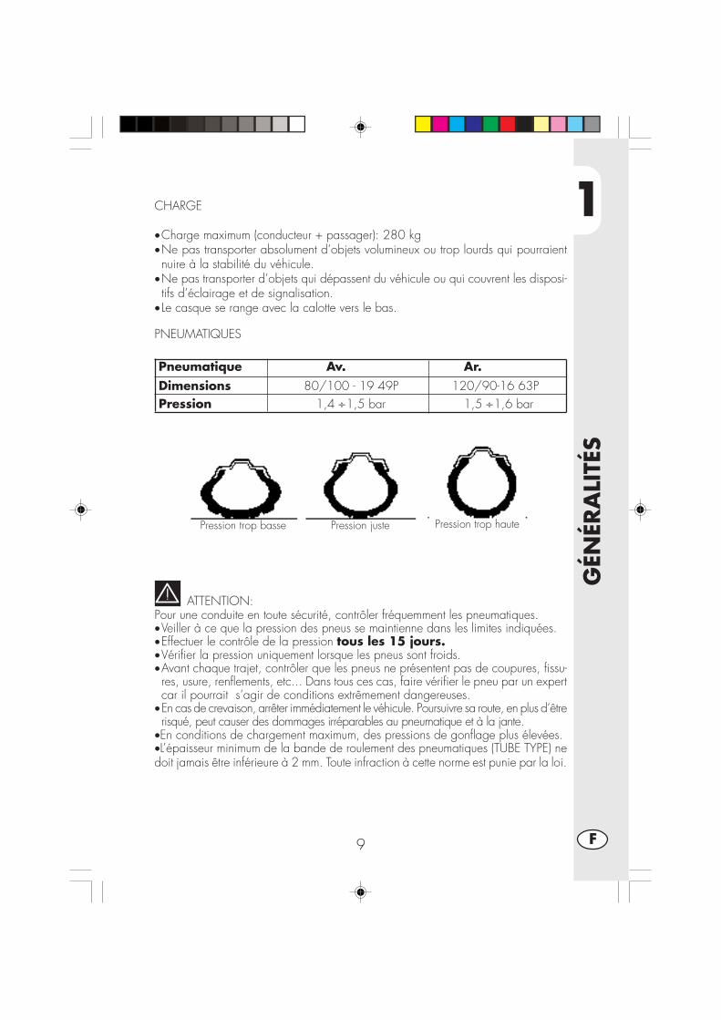
1
GÉN
ÉRA
LITÉ
S
9 F
CHARGE
•Charge maximum (conducteur + passager): 280 kg•Ne pas transporter absolument d’objets volumineux ou trop lourds qui pourraientnuire à la stabilité du véhicule.
•Ne pas transporter d’objets qui dépassent du véhicule ou qui couvrent les disposi-tifs d’éclairage et de signalisation.
• Le casque se range avec la calotte vers le bas.
PNEUMATIQUES
ATTENTION:Pour une conduite en toute sécurité, contrôler fréquemment les pneumatiques.•Veiller à ce que la pression des pneus se maintienne dans les limites indiquées.•Effectuer le contrôle de la pression tous les 15 jours.•Vérifier la pression uniquement lorsque les pneus sont froids.•Avant chaque trajet, contrôler que les pneus ne présentent pas de coupures, fissu-res, usure, renflements, etc... Dans tous ces cas, faire vérifier le pneu par un expertcar il pourrait s’agir de conditions extrêmement dangereuses.
•En cas de crevaison, arrêter immédiatement le véhicule. Poursuivre sa route, en plus d’êtrerisqué, peut causer des dommages irréparables au pneumatique et à la jante.
•En conditions de chargement maximum, des pressions de gonflage plus élevées.•L’épaisseur minimum de la bande de roulement des pneumatiques (TUBE TYPE) nedoit jamais être inférieure à 2 mm. Toute infraction à cette norme est punie par la loi.
Pneumatique Av. Ar. Dimensions 80/100 - 19 49P 120/90-16 63P Pression 1,4 ÷1,5 bar 1,5 ÷1,6 bar
Pression trop basse Pression trop hautePression juste

1
GÉN
ÉRA
LITÉ
S
10F
CONNAISSANCE DU VEHICULE
1
2
34
5
7
8
9
19
20
13
14
10
15
16
12
17
11
11
18
21
22
24
25
24
17
6

1
GÉN
ÉRA
LITÉ
S
11 F
Eléments principaux:
1 - Filtre De Conduite2 - Reservoir carb.3 - Bouchon réservoir essence4 - Silencieux5 - Amortisseur AR.6 - Projecteur7 - Clignotant AV.8 - Feu AR.
9 - Clignotant AR.
10 - Béquille lat.11 - Retroviseur12 - Repose-pied passager13 - Fourche14 - Repose-pieds15 - Selle16 - Moteur17 - Garde boue AV.18 - Porte-plaque19 - Levier du démarrage20 - Antivol casque21 - Châssis22 - Chaîne23 - Cache-chaîne24 - Etrier de frein AV.25 - Etrier de frein AR.

1
GÉN
ÉRA
LITÉ
S
12F
CLÉSLa moto est fournie avec deux clés; lesdeux clés sont à uti l iser pour lecommutateur/verrou de direction et pourla serrure casque.
ATTENTION:Ne pas conserver la clé de réserve àl’intérieur du véhicule mais dans un lieusûr et à portée de main. Nous conseillonsd’enregistrer sur ce manuel (ou ailleurs)le numéro de code imprimé sur les clés.En cas de perte des deux clés, il estpossible de demander des doubles.
CONTACTEUR PRINCIPAL/VERROUILLAGEDE DIRECTIONContrôler le circuit d’allumage, la miseen service du verrouillage de direction etl’ouverture de la selle.
OFF: Système électrique coupé.ON: L’allumage du véhicule est possi-
ble.LOCK:Verrouillage de la direction. Pour
cette opération, il faut braquer leguidon à gauche, appuyer surla clé, la tourner complètementvers la gauche et relâcher.
SERRURE POUR CASQUEIntroduire la clé dans la serrure située àgauche sous la selle et la tourner àgauche pour ouvrir le crochet pourcasque.
ONOFF
LOCK
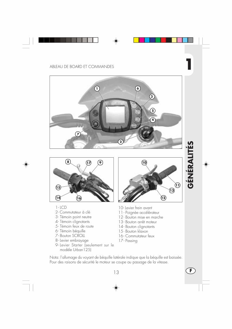
1
GÉN
ÉRA
LITÉ
S
13 F
1- LCD2- Commutateur à clé3- Témoin point neutre4- Témoin clignotants5- Témoin feux de route6- Témoin béquille7- Bouton SCROLL8- Levier embrayage9- Levier Starter (seulement sur le
modèle Urban125)
10- Levier frein avant11 - Poignée accélérateur12 - Bouton mise en marche13 - Bouton arrêt moteur14 - Bouton clignotants15 - Bouton klaxon16 - Commutateur feux17 - Passing
ABLEAU DE BOARD ET COMMANDES
Nota: l’allumage du voyant de béquille latérale indique que la béquille est baissée.Pour des raisons de sécurité le moteur se coupe au passage de la vitesse.
2
10
11
8
1
9
6
3
5
4
7
12
13
14
15
16
17
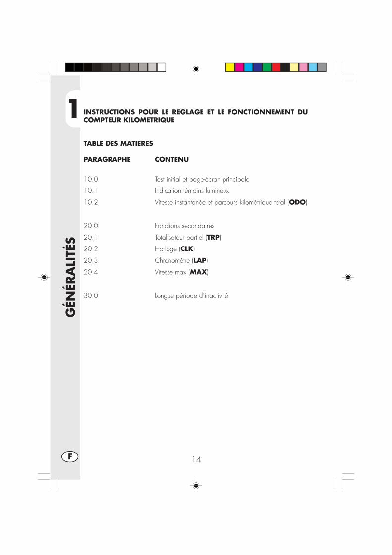
1
GÉN
ÉRA
LITÉ
S
14F
INSTRUCTIONS POUR LE REGLAGE ET LE FONCTIONNEMENT DUCOMPTEUR KILOMETRIQUE
TABLE DES MATIERES
PARAGRAPHE CONTENU
10.0 Test initial et page-écran principale
10.1 Indication témoins lumineux
10.2 Vitesse instantanée et parcours kilométrique total (ODO)
20.0 Fonctions secondaires
20.1 Totalisateur partiel (TRP)
20.2 Horloge (CLK)
20.3 Chronomètre (LAP)
20.4 Vitesse max (MAX)
30.0 Longue période d’inactivité
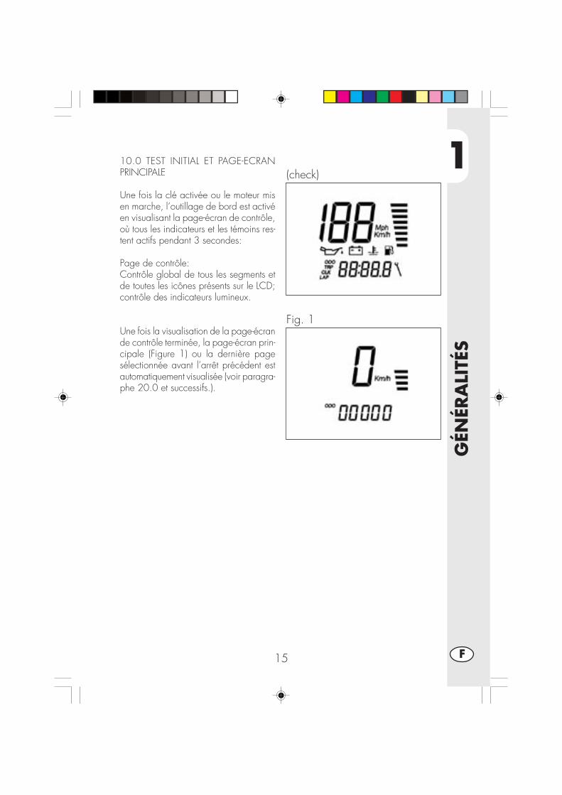
1
GÉN
ÉRA
LITÉ
S
15 F
10.0 TEST INITIAL ET PAGE-ECRANPRINCIPALE
Une fois la clé activée ou le moteur misen marche, l’outillage de bord est activéen visualisant la page-écran de contrôle,où tous les indicateurs et les témoins res-tent actifs pendant 3 secondes:
Page de contrôle:Contrôle global de tous les segments etde toutes les icônes présents sur le LCD;contrôle des indicateurs lumineux.
Une fois la visualisation de la page-écrande contrôle terminée, la page-écran prin-cipale (Figure 1) ou la dernière pagesélectionnée avant l’arrêt précédent estautomatiquement visualisée (voir paragra-phe 20.0 et successifs.).
(check)
Fig. 1

1
GÉN
ÉRA
LITÉ
S
16F
10.1 INDICATION TÉMOINS LUMI-NEUX ET BOUTON SCROLL
L’outillage est doté de 4 témoinslumineux avec fonction de signalisationet d’avis:
•Témoin Béquille rouge A: lorsqu’il estallumé, il signale que la béquillelatérale de la moto est baissée.
•Témoin Neutral vert B: lorsqu’il estallumé, il signale que le levier chan-gement de vitesse est en position depoint mort.
•Témoin Feu de route bleu C: lorsqu’ilest allumé, il signale que le feu deroute est allumé.
•Témoin Clignotants vert D: lorsqu’ilest allumé, il signale que les cligno-tants (droits ou gauches) sont activés.
•Bouton Scroll E, il permet de bougerà l’intérieur de l’outillage en sélection-nant la fonction requise (Voir leparagraphe 20.0 et successifs)
A
B
C
DE
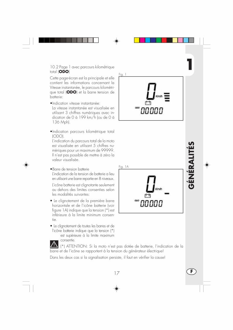
1
GÉN
ÉRA
LITÉ
S
17 F
Fig. 1
Fig. 1A
10.2 Page 1 avec parcours kilométriquetotal (ODO)
Cette page-écran est la principale et ellecontient les informations concernant laVitesse instantanée, le parcours kilométri-que total (ODO) et la barre tension debatterie:
•Indication vitesse instantanée:La vitesse instantanée est visualisée enutilisant 3 chiffres numériques avec in-dication de 0 à 199 km/h (ou de 0 à136 Mph).
•Indication parcours kilométrique total(ODO).L’indication du parcours total de la motoest visualisée en utilisant 5 chiffres nu-mériques pour un maximum de 99999.Il n’est pas possible de mettre à zéro lavaleur visualisée.
•Barre de tension batterieL’indication de la tension de batterie a lieuen utilisant une barre repartie en 8 niveaux.
L’icône batterie est clignotante seulementau dehors des limites consenties selonles modalités suivantes:
• Le clignotement de la première barrehorizontale et de l’icône batterie (voirfigure 1A) indique que la tension (*) estinférieure à la limite minimum consen-tie.
• Le clignotement de toutes les barres et del’icône batterie indique que la tension (*)
est supérieure à la limite maximumconsentie.(*) ATTENTION: Si la moto n’est pas dotée de batterie, l’indication de la
barre et de l’icône se rapportent à la tension du générateur électrique!
Dans les deux cas si la signalisation persiste, il faut en vérifier la cause!
1
GÉN
ÉRA
LITÉ
S
18F
20.0 FONCTIONS SECONDAIRES
De la page-écran principale il est possible d’accéder de façon séquentielle auxfonctions secondaires successives qui permettent de visualiser les informations selonla liste suivante:
Totalisateur partiel (TRP)
Horloge (CLK)
Chronomètre (LAP)
Vitesse max (MAX)
En tout cas, outre l’information concernant la page-écran spécifique, les indicationsde vitesse instantanée et barre/icône tension de batterie continueront à être visuali-sées sur l’écran.
Toutes les pages-écran à partir de la page-écran principale (ODO) ne peuvent êtrevisualisées que dans leur séquence en effectuant une courte pression sur le boutonSCROLL. Cela signifie que l’ordre de visualisation sera le suivant:
ODO -> TRP -> CLK -> LAP -> MAX
Naturellement, si vous pressez le bouton SCROLL quand la page-écran de Vitessemax est présente (MAX), vous passerez à nouveau à la page principale (ODO) etla séquence pourra reprendre comme vous voulez.
ATTENTION:L’EMPLOI DU BOUTON SCROLL N’EST PAS CONSENTI PENDANT LA MARCHEDE LA MOTO, C’EST-A-DIRE QUAND L’INDICATION DE VITESSE INSTANTANEEEST DIFFERENTE DE 0 Km/h-Mph.
CELA POUR GARANTIR LA NECESSAIRE SECURITE PENDANT LA CONDUITE DELA MOTO.

1
GÉN
ÉRA
LITÉ
S
19 F
Fig. 2
20.1 Totalisateur partiel TRP
De la figure 1, avec la moto en positionarrêtée, en effectuant une courte pressionsur le bouton SCROLL vous passez à lafigure 2 contenant les informations deVitesse instantanée, de parcours kilomé-trique partiel (TRP) et de barre tensionbatterie:
•Km/h (Mph) avec indication sur 3 chif-fres (grands).
•Totalisateur partiel TRP sur 4 chiffres(petits)
•Barre tension de batterie
Le totalisateur partiel utilise 4 chiffres dansle format 000,0 qui permet de mesurerla distance partielle d’une valeur de0,0Km/Mille à 999,9 Km/Mille. Unefois arrivés à l’indication 999,9, au par-cours successif de 0,1Km ou Mille l’indi-cation passe automatiquement à la va-leur 0,0.
Il est possible d’effectuer la mise à zéromanuelle (avec figure 2 activée), avec lamoto en position arrêtée, en poussant surle bouton SCROLL pendant un laps detemps égal à environ 3 secondes jusqu’àla visualisation de l’indication “—.-“ surles 4 chiffres petits.
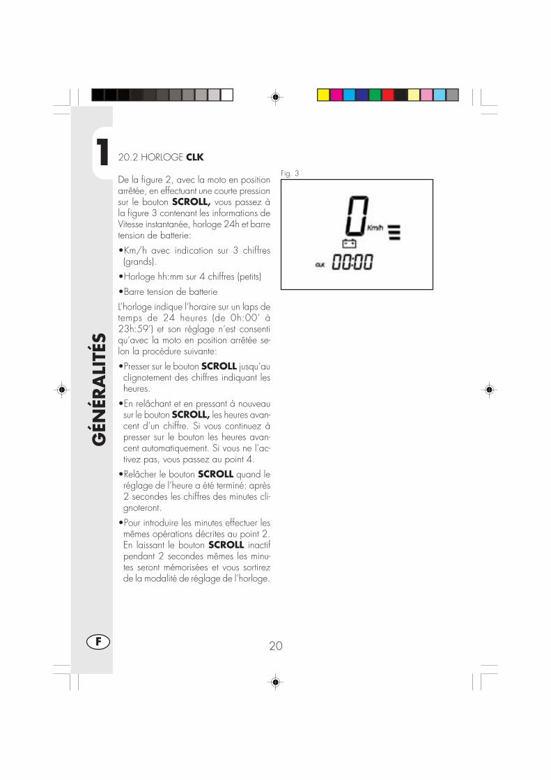
1
GÉN
ÉRA
LITÉ
S
20F
Fig. 3
20.2 HORLOGE CLK
De la figure 2, avec la moto en positionarrêtée, en effectuant une courte pressionsur le bouton SCROLL, vous passez àla figure 3 contenant les informations deVitesse instantanée, horloge 24h et barretension de batterie:
•Km/h avec indication sur 3 chiffres(grands).
•Horloge hh:mm sur 4 chiffres (petits)
•Barre tension de batterie
L’horloge indique l’horaire sur un laps detemps de 24 heures (de 0h:00’ à23h:59’) et son réglage n’est consentiqu’avec la moto en position arrêtée se-lon la procédure suivante:
•Presser sur le bouton SCROLL jusqu’auclignotement des chiffres indiquant lesheures.
•En relâchant et en pressant à nouveausur le bouton SCROLL, les heures avan-cent d’un chiffre. Si vous continuez àpresser sur le bouton les heures avan-cent automatiquement. Si vous ne l’ac-tivez pas, vous passez au point 4.
•Relâcher le bouton SCROLL quand leréglage de l’heure a été terminé: après2 secondes les chiffres des minutes cli-gnoteront.
•Pour introduire les minutes effectuer lesmêmes opérations décrites au point 2.En laissant le bouton SCROLL inactifpendant 2 secondes mêmes les minu-tes seront mémorisées et vous sortirezde la modalité de réglage de l’horloge.
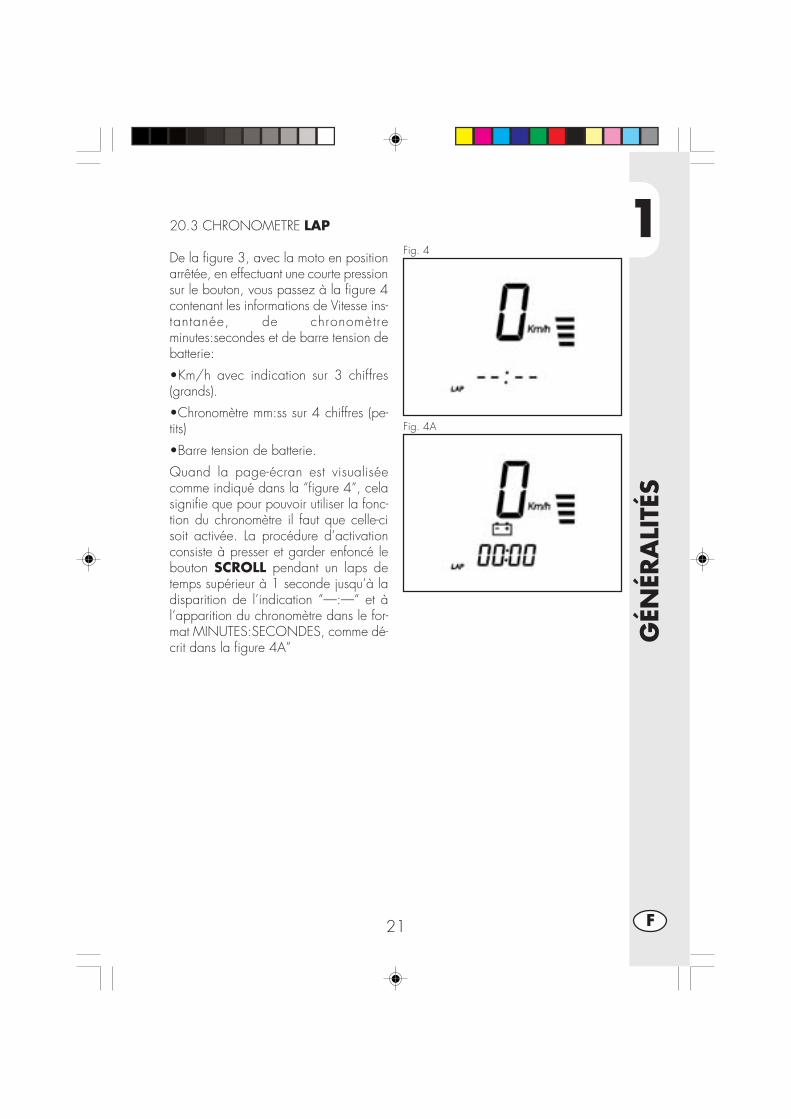
1
GÉN
ÉRA
LITÉ
S
21 F
Fig. 4
20.3 CHRONOMETRE LAP
De la figure 3, avec la moto en positionarrêtée, en effectuant une courte pressionsur le bouton, vous passez à la figure 4contenant les informations de Vitesse ins-tantanée, de chronomètreminutes:secondes et de barre tension debatterie:
•Km/h avec indication sur 3 chiffres(grands).
•Chronomètre mm:ss sur 4 chiffres (pe-tits)
•Barre tension de batterie.
Quand la page-écran est visualiséecomme indiqué dans la “figure 4”, celasignifie que pour pouvoir utiliser la fonc-tion du chronomètre il faut que celle-cisoit activée. La procédure d’activationconsiste à presser et garder enfoncé lebouton SCROLL pendant un laps detemps supérieur à 1 seconde jusqu’à ladisparition de l’indication “—:—“ et àl’apparition du chronomètre dans le for-mat MINUTES:SECONDES, comme dé-crit dans la figure 4A”
Fig. 4A

1
GÉN
ÉRA
LITÉ
S
22F
Fonctionnement: le départ et l’arrêt du chronomètre, soit manuellementqu’automatiquement, ne pourront avoir lieu qu’avec l’outillage réglé comme indiquésur la “figura 4A”:
•Pour le départ et l’arrêt manuel presser sur le bouton en utilisant une impulsioncourte soit pour le départ que pour l’arrêt (Actif seulement avec la moto arrêtée).
•Le départ automatique a lieu au moment de la mise en marche de la moto et l’arrêtautomatique a lieu environ 1 seconde après l’arrêt de la moto (avec correctionautomatique de la valeur indiquée).
L’arrêt du comptage a lieu aussi quand la moto déjà en marche est arrêtée (même si ledépart avait été effectué de façon manuelle), à condition que la fonction LAP soit active.
Fig. 4ACette figure visualise le chronomètre avecle temps passé: si le comptage est arrêtéet mis à zéro, tous les chiffres visualisésseront zéro, comme indiqué dans la figu-re 4A.Le sigle “LAP” clignotant indique que lechronomètre est actif et qu’il sera présentaussi pendant la visualisation des autrespages d’information.En effet, il est possible de passer àd’autres fonctions qui ne se réfèrent pasau chronomètre selon les modalitéssuivantes même avec le chronomètre actif.Mise à zéro du chronomètre:Presser sur le bouton SCROLL de la fi-gure 4A pendant un laps de tempssupérieur à 2 secondes; tout d’abord seravisualisée la figure 4 et puis encore lafigure 4A avec l’indication du tempsmarqué par le chronomètre. Une fois lebouton SCROLL relâché, le chronomètresera mis à zéro et arrêté.Sortie (désactivation) de la figu-re LAP:Presser le bouton de page 4A pendantun laps de temps compris entre 1 et 2secondes jusqu’à la visualisation de lapage 4 et puis relâcher le bouton. Eneffectuant encore une courte pression surle bouton, vous passez à la page suc-cessive. Le chronomètre restera enfonction si activé et le sigle LAP clignotera.

1
GÉN
ÉRA
LITÉ
S
23 F
Fig. 5
20.4 VITESSE MAX MAX
De la figure 4, avec la moto en positionarrêtée, en effectuant une courte pressionsur le bouton SCROLL, vous passezà la figure 5 contenant les informationsde Vitesse instantanée, vitesse maxobtenue et barre tension de batterie:
•Km/h avec indication sur 3 chiffres(grands).
•Vitesse max obtenue sur 3 chiffres (petits)
•Barre tension de batterie.
Sur cette page-écran l’indication “Km/h” ou “Mph” est clignotante.
Pendant la marche de la moto l’indicationde vitesse max atteinte est constammentmise à jour et indiqué sur les 3 chiffrespetits. De toute façon cette valeur estmémorisée même si la figura 5 n’est pasactive.
Pour la mise à zéro de l’indication (avecfigure 5 active), avec la moto en positionarrêtée, garder enfoncé le boutonSCROLL pendant un laps de tempsd’environ 3 secondes, jusqu’à lavisualisation de l’indication “—“ sur les3 chiffres petits.
Pour tourner à la figure initiale 1 il estnécessaire d’effectuer une courte pressionsur le bouton SCROLL.
30.0 Longue période d’inactivité
L’outillage digital est alimenté par la bat-terie de la moto, en cas de longuepériode d’inactivité il est de règle dedétacher la batterie.De toute façon, cette opération impliquela perte des valeurs introduite concernantl’heure et la vitesse max obtenue.
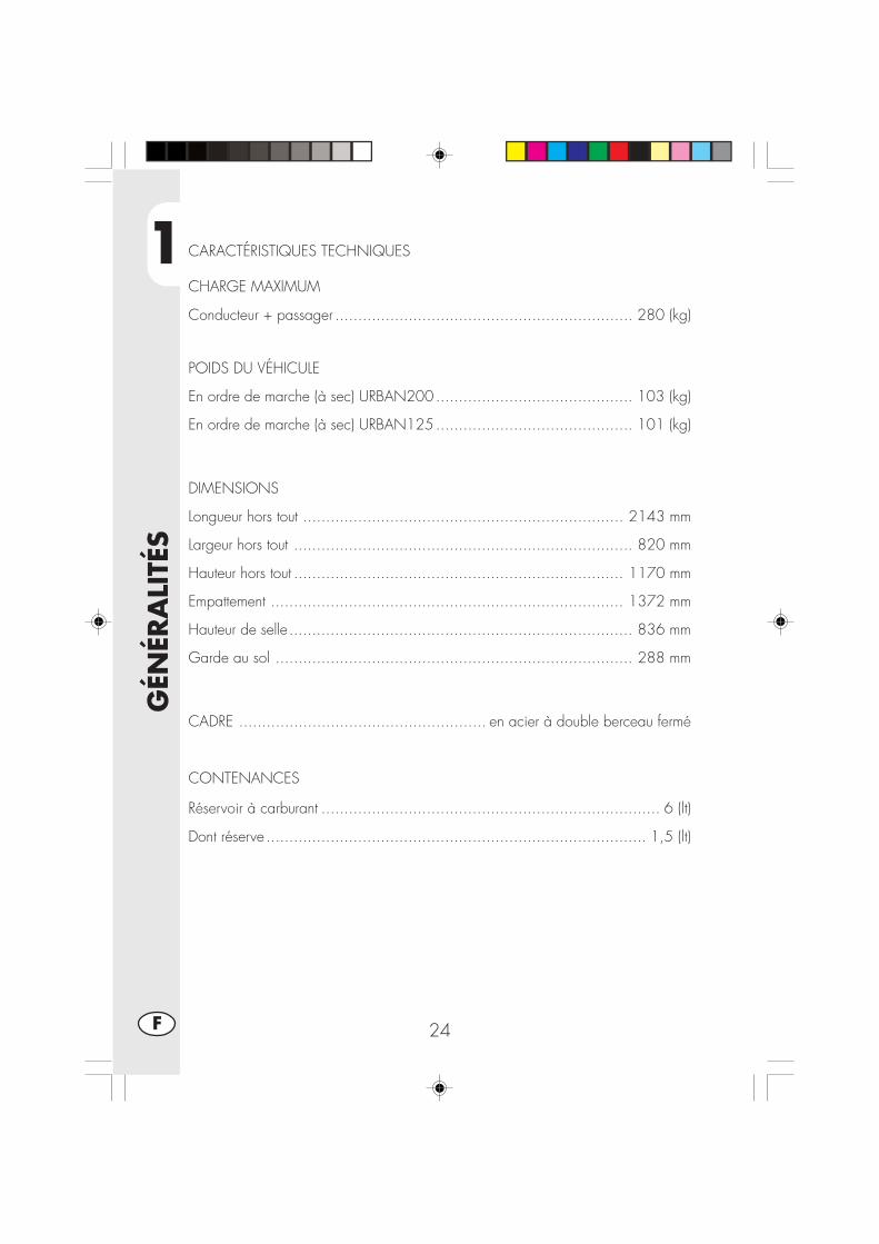
1
GÉN
ÉRA
LITÉ
S
24F
CARACTÉRISTIQUES TECHNIQUES
CHARGE MAXIMUM
Conducteur + passager ................................................................. 280 (kg)
POIDS DU VÉHICULE
En ordre de marche (à sec) URBAN200........................................... 103 (kg)
En ordre de marche (à sec) URBAN125........................................... 101 (kg)
DIMENSIONS
Longueur hors tout ...................................................................... 2143 mm
Largeur hors tout .......................................................................... 820 mm
Hauteur hors tout ........................................................................ 1170 mm
Empattement ............................................................................. 1372 mm
Hauteur de selle........................................................................... 836 mm
Garde au sol .............................................................................. 288 mm
CADRE ...................................................... en acier à double berceau fermé
CONTENANCES
Réservoir à carburant .......................................................................... 6 (lt)
Dont réserve ................................................................................... 1,5 (lt)
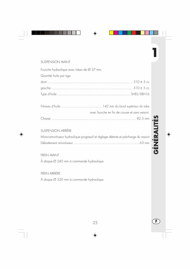
1
GÉN
ÉRA
LITÉ
S
25 F
SUSPENSION AVANT
Fourche hydraulique avec tubes de Ø 37 mm.
Quantité huile par tige:
droit ...................................................................................... 310 ± 5 cc
gauche .................................................................................. 310 ± 5 cc
Type d’huile ......................................................................... SHELL EBH16
Niveau d’huile .......................................... 142 mm du bord supérieur du tube
avec fourche en fin de course et sans ressort.
Chasse ..................................................................................... 82,5 mm
SUSPENSION ARRIÈRE
Mono-amortisseur hydraulique progressif et réglage détente et précharge du ressort
Débattement amortisseur .................................................................. 63 mm
FREIN AVANT
À disque Ø 245 mm à commande hydraulique
FREIN ARRIÈRE
À disque Ø 220 mm à commande hydraulique

1
GÉN
ÉRA
LITÉ
S
26F
MOTEUR URBAN 125
Type .................................Monocylindrique, incliné en avant, 4 temps, SOHC
Alésage x course ...................................................................... 54x54 mm
Cylindrée (cm3) ............................................................................ 124 cm3
Rapport de compression ..................................................................... 10.1
Carburateur ...................................................... MIKUNI UCAL 5N Ø26-38
Graissage .................................................................. par huile dans carter
Alimentation ...... à essence (indice d’octane minimum 95 sans plomb) par carburateur
Refroidissement ............................................................ par circulation d’aire
Bougie ........................................................................... NGK R CR7 HSA
Embrayage ........................................................... multidisque à bain d’huile
Boîte de vitesses ......................................................................... 5 vitesses
Rapport de démultiplication primaire .................................................. 68/20
Rapport de démultiplication final ....................................................... 60/14
Rapport des vitesses 1° ................................................................... 37/14
2° ................................................................... 32/18
3° ................................................................... 25/19
4° ................................................................... 23/22
5° ................................................................... 21/24
Chaîne de transmission ............................. REGINA DERVIO 1/2, 5/16 P. 136
Jeu aux soupapes .... admission mm 0,08 - 0,12 échappement mm 0,10 - 0,14
Démarrage ......................................................... électrique et/ou kick-starter
Huile moteur .......................................................... BARDAHL XTM15W 50
Quantité d’huile moteur .................................................. l1,00 ml/1,050 mll

1
GÉN
ÉRA
LITÉ
S
27 F
MOTEUR URBAN 200
Type ...........................................monocylindre à quatre temps SUZUKI H402
Alésage x course ................................................................... 66x58,2 mm
Cylindrée (cm3) ............................................................................ 199 cm3
Rapport de compression .................................................................... 9,4:1
Carburateur .............................................................. MIKUNI BST31 42AD
Graissage .................................................................. par huile dans carter
Alimentation ...... à essence (indice d’octane minimum 95 sans plomb) par carburateur
Refroidissement ............................................................ par circulation d’aire
Bougie ................................................................................ NGK DR8 EA
Embrayage ........................................................... multidisque à bain d’huile
Boîte de vitesses ......................................................................... 5 vitesses
Rapport de démultiplication primaire ...................................... 3,157 (60/19)
Rapport de démultiplication final ........................................... 3,200 (48/15)
Rapport des vitesses 1° ....................................................... 3,000 (33/11)
2° ....................................................... 1,933 (29/15)
3° ....................................................... 1,437 (23/16)
4° ....................................................... 1,095 (23/21)
5° ....................................................... 0,913 (21/23)
Chaîne de transmission ......................................... REGINA 5/8, 1/4, P.104
Jeu aux soupapes .......................... admission et échappement mm 0,08 - 0,13
Démarrage ......................................................... électrique et/ou kick-starter
Huile moteur .......................................................... BARDAHL XTM15W 50
Quantité d’huile moteur ........ vidange seule 850 mL avec remplacement filtre 950 mlrévision 1300 ml

1
GÉN
ÉRA
LITÉ
S
28F
SCHÉMA ÉLECTRIQUE URBAN 125
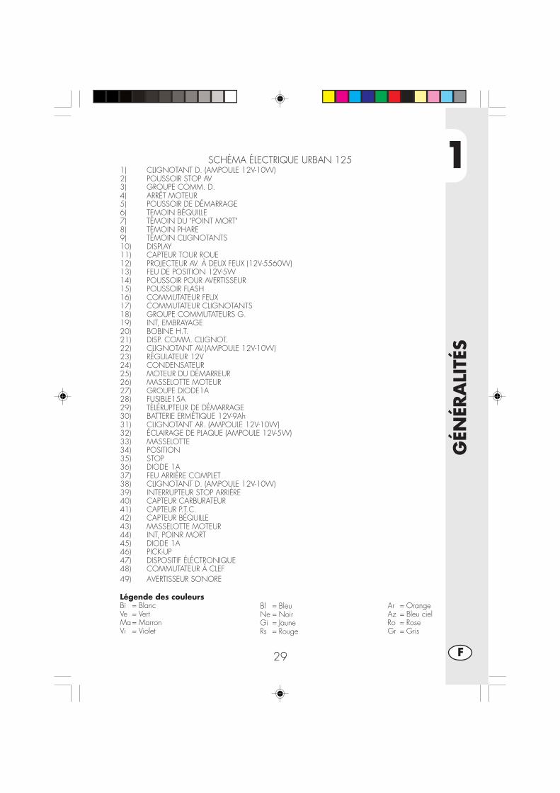
1
GÉN
ÉRA
LITÉ
S
29 F
Légende des couleursBi = BlancVe = VertMa= MarronVi = Violet
Bl = BleuNe = NoirGi = JauneRs = Rouge
Ar = OrangeAz = Bleu cielRo = RoseGr = Gris
SCHÉMA ÉLECTRIQUE URBAN 1251) CLIGNOTANT D. (AMPOULE 12V-10W)2) POUSSOIR STOP AV3) GROUPE COMM. D.4) ARRÊT MOTEUR5) POUSSOIR DE DÉMARRAGE6) TEMOIN BÉQUILLE7) TÉMOIN DU "POINT MORT"8) TÉMOIN PHARE9) TÉMOIN CLIGNOTANTS10) DISPLAY11) CAPTEUR TOUR ROUE12) PROJECTEUR AV. À DEUX FEUX (12V-5560W)13) FEU DE POSITION 12V-5W14) POUSSOIR POUR AVERTISSEUR15) POUSSOIR FLASH16) COMMUTATEUR FEUX17) COMMUTATEUR CLIGNOTANTS18) GROUPE COMMUTATEURS G.19) INT, EMBRAYAGE20) BOBINE H.T.21) DISP. COMM. CLIGNOT.22) CLIGNOTANT AV.(AMPOULE 12V-10W)23) RÉGULATEUR 12V24) CONDENSATEUR25) MOTEUR DU DÉMARREUR26) MASSELOTTE MOTEUR27) GROUPE DIODE1A28) FUSIBLE15A29) TÉLÉRUPTEUR DE DÉMARRAGE30) BATTERIE ERMÉTIQUE 12V-9Ah31) CLIGNOTANT AR. (AMPOULE 12V-10W)32) ÉCLAIRAGE DE PLAQUE (AMPOULE 12V-5W)33) MASSELOTTE34) POSITION35) STOP36) DIODE 1A37) FEU ARRIÈRE COMPLET38) CLIGNOTANT D. (AMPOULE 12V-10W)39) INTERRUPTEUR STOP ARRIÈRE40) CAPTEUR CARBURATEUR41) CAPTEUR P.T.C.42) CAPTEUR BÉQUILLE43) MASSELOTTE MOTEUR44) INT, POINR MORT45) DIODE 1A46) PICK-UP47) DISPOSITIF ÉLÉCTRONIQUE48) COMMUTATEUR À CLEF49) AVERTISSEUR SONORE

1
GÉN
ÉRA
LITÉ
S
30F
SCHÉMA ÉLECTRIQUE URBAN 200
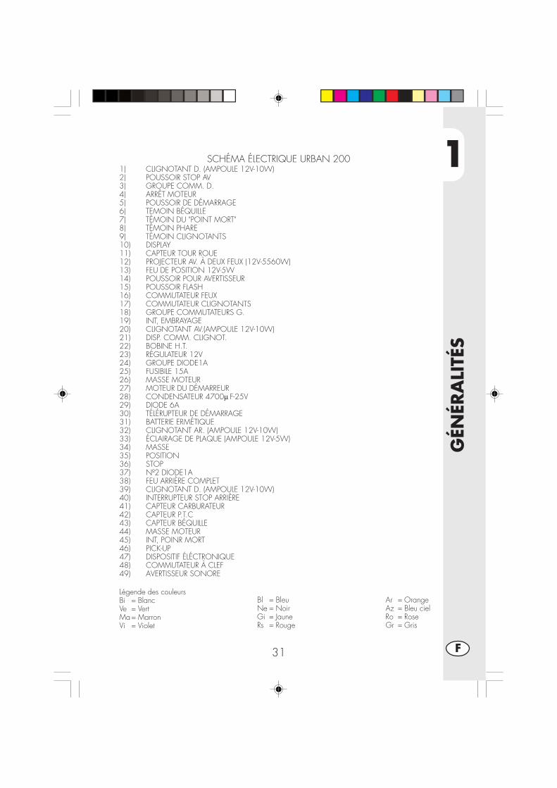
1
GÉN
ÉRA
LITÉ
S
31 F
Légende des couleursBi = BlancVe = VertMa= MarronVi = Violet
Bl = BleuNe = NoirGi = JauneRs = Rouge
Ar = OrangeAz = Bleu cielRo = RoseGr = Gris
SCHÉMA ÉLECTRIQUE URBAN 2001) CLIGNOTANT D. (AMPOULE 12V-10W)2) POUSSOIR STOP AV3) GROUPE COMM. D.4) ARRÊT MOTEUR5) POUSSOIR DE DÉMARRAGE6) TEMOIN BÉQUILLE7) TÉMOIN DU "POINT MORT"8) TÉMOIN PHARE9) TÉMOIN CLIGNOTANTS10) DISPLAY11) CAPTEUR TOUR ROUE12) PROJECTEUR AV. À DEUX FEUX (12V-5560W)13) FEU DE POSITION 12V-5W14) POUSSOIR POUR AVERTISSEUR15) POUSSOIR FLASH16) COMMUTATEUR FEUX17) COMMUTATEUR CLIGNOTANTS18) GROUPE COMMUTATEURS G.19) INT, EMBRAYAGE20) CLIGNOTANT AV.(AMPOULE 12V-10W)21) DISP. COMM. CLIGNOT.22) BOBINE H.T.23) RÉGULATEUR 12V24) GROUPE DIODE1A25) FUSIBILE 15A26) MASSE MOTEUR27) MOTEUR DU DÉMARREUR28) CONDENSATEUR 4700μ F-25V29) DIODE 6A30) TÉLÉRUPTEUR DE DÉMARRAGE31) BATTERIE ERMÉTIQUE32) CLIGNOTANT AR. (AMPOULE 12V-10W)33) ÉCLAIRAGE DE PLAQUE (AMPOULE 12V-5W)34) MASSE35) POSITION36) STOP37) Nº2 DIODE1A38) FEU ARRIÈRE COMPLET39) CLIGNOTANT D. (AMPOULE 12V-10W)40) INTERRUPTEUR STOP ARRIÈRE41) CAPTEUR CARBURATEUR42) CAPTEUR P.T.C43) CAPTEUR BÉQUILLE44) MASSE MOTEUR45) INT, POINR MORT46) PICK-UP47) DISPOSITIF ÉLÉCTRONIQUE48) COMMUTATEUR À CLEF49) AVERTISSEUR SONORE

1
GÉN
ÉRA
LITÉ
S
32F
BATTERIEPour accéder à la batterie A enlever laselle, comme décrit dans la section“Démontage du châssis” à la page 52.
Enlever le couvercle B en dévissant lavis C, décrocher l’élastique D,déconnecter les câbles et en labatterie.
ATTENTION:Afin d'éviter d'endommager la partieélectrique, ne jamais déconnecter lesfils avec le moteuren marche.Remettre la batterie (A) dans sonemplacement sous la selle en la fixantavec l'élastique (B).Connecter l'extrémité des fils de couleurnoire au négatif (-) et les deux câblesde couleur rouge au positif (+) puisinsérer la protection (voir schéma).
CENTRALLa central E est placée sur le côtégauche de la moto, pour accéder à cedispositif il faut enlever la joue gauchesituée sous le réservoir comme décrit àla page 53.
KLAXONLe Klaxon F est situé en position avant,sur le côté gauche de la moto.
ÉQUIPEMENT ÉLECTRIQUE
AD
F
B C
E
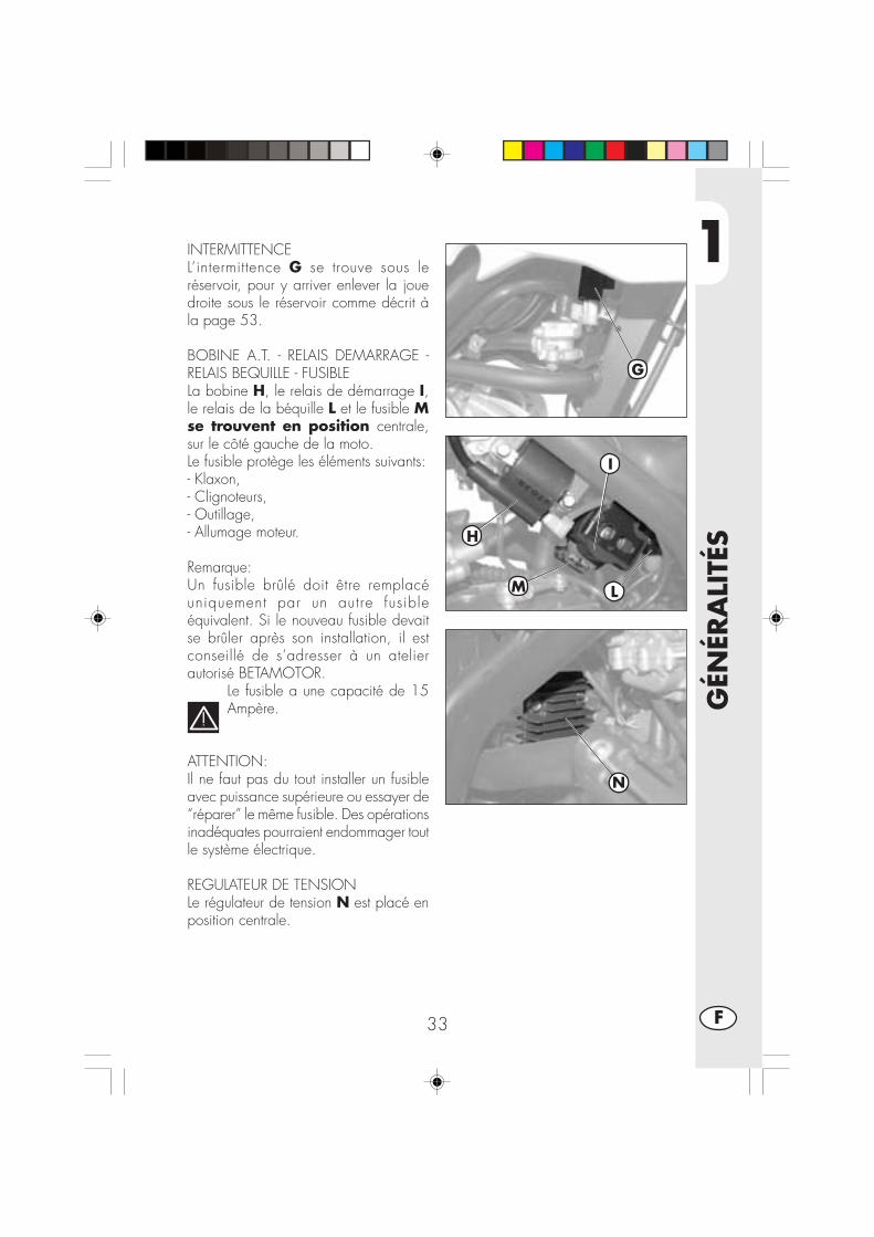
1
GÉN
ÉRA
LITÉ
S
33 F
INTERMITTENCEL’intermittence G se trouve sous leréservoir, pour y arriver enlever la jouedroite sous le réservoir comme décrit àla page 53.
BOBINE A.T. - RELAIS DEMARRAGE -RELAIS BEQUILLE - FUSIBLELa bobine H, le relais de démarrage I,le relais de la béquille L et le fusible Mse trouvent en position centrale,sur le côté gauche de la moto.Le fusible protège les éléments suivants:- Klaxon,- Clignoteurs,- Outillage,- Allumage moteur.
Remarque:Un fusible brûlé doit être remplacéuniquement par un autre fusibleéquivalent. Si le nouveau fusible devaitse brûler après son installation, il estconseillé de s’adresser à un atelierautorisé BETAMOTOR.
Le fusible a une capacité de 15Ampère.
ATTENTION:Il ne faut pas du tout installer un fusibleavec puissance supérieure ou essayer de“réparer” le même fusible. Des opérationsinadéquates pourraient endommager toutle système électrique.
REGULATEUR DE TENSIONLe régulateur de tension N est placé enposition centrale.
H
L
N
I
M
G

1
GÉN
ÉRA
LITÉ
S
34F
SOUPAPE AISLa soupape AIS est un système d’injectiond’air qui permet d’achever la combustiond’hydrocarbures non brûlés, à savoir lerésidu du cycle thermodynamique.Pour accéder à la soupape A il fautenlever la protection droite sous leréservoir comme décrit à la page 52
A
2
UTI
LISA
TIO
N D
U V
ÉHIC
ULE
35 F
TABLE DES MATIÈRES
CHAP. 2 UTILISATION DU VÉHICULE
Contrôles et entretien avant et après l’utilisation en tout-terrain
Lubrifiants et liquides conseillés
Rodage
Démarrage du moteur
Arrêt du moteur
Approvisionnement en carburant
2
UTI
LISA
TIO
N D
U V
ÉHIC
ULE
36F
CONTRÔLES ET ENTRETIEN AVANT ET APRÈS L’UTILISATION EN TOUT-TERRAIN
Pour éviter des problèmes ennuyeux pendant le fonctionnement du véhicule, il estpréférable d’effectuer aussi bien avant qu’après l’utilisation, quelques opérations decontrôle et d’entretien. En effet, quelques minutes consacrées à ces opérations, enplus de rendre la conduite plus sûre, peuvent vous faire économiser du temps et del’argent. Il faut donc procéder ainsi:
PNEUMATIQUES vérifier la pression de gonflage, l’état général et l’épaisseur de labande (Tu vois page 9)
RAYONS vérifier la tension correcteBOULONNERIE vérifier le serrage de toute la boulonnerieCHAÎNE vérifier la tension (flèche de 20 mm) et graisser si nécessaireFILTRE A AIR nettoyer le filtre et l’humecter d’huile (Tu vois page 48)
Nota:Contrôler la présence des papiers du véhicule.Les jours de froid, il est préférable de chauffer le moteur en le laissant tourner auralenti quelques minutes avant de se mettre en route. Toutes les fois que le véhiculeest utilisé en tout-terrain, il faut le laver soigneusement.

2
UTI
LISA
TIO
N D
U V
ÉHIC
ULE
37 F
LUBRIFIANTS ET LIQUIDES CONSEILLES
Pour un meilleur fonctionnement et une plus grande longévité de la moto, il estrecommandé d’utiliser de préférence les produits du tableau:
TYPE DE PRODUIT CARACTÉRISTIQUES
HUILE MOTEUR BARDAHL XTM 15W 50
LIQUIDE DE FREINS BARDAHL BRAKE FLUID DOT4
HUILE DE FOURCHE SHELL EBH 16
GRAISSE POUR TRANSMISSION BARDAHL Outboard Grease NLGI2
Nota:Lors des vidanges et renouvellements de fluides, il est recommandé de respecterscrupuleusent le tableau (tu vois page 57)
RODAGELe rodage correspond à une dizaine d’heures d’activité, pendant cette période il estconseillé de:•Utiliser le véhicule après avoir bien chauffé le moteur•Eviter de rouler à vitesse constante (en variant la vitesse, les différents composantsse tasseront de manière plus uniforme en un temps plus réduit)
•Eviter de tourner la poignée de l’accélérateur plus de 3/4
ATTENTION:•Au bout de 1000 premiers kilomètres de trajet, vidanger l’huile du moteur•Toujours utiliser de l’essence super sans plomb•Après la première sortie en tout-terrain, contrôler toute la boulonnerie.

2
UTI
LISA
TIO
N D
U V
ÉHIC
ULE
38F
DEMARRAGE DU MOTEUR
•Positionner le robinet du réservoir ducarburant en position OUVERT (voirdessin annexé).
•Tourner la clé du commutateur dans lesens des aiguilles d’une montre et s’as-surer que le témoin du point mort, placésur le tableau de bord, est allumé (voirremarque 3 à la page 13).
•S’assurer que l’interrupteur d’urgence A,placé sur la commande du gaz, est enposition ON.
Remarque:A moteur froid, actionner le starter D.
Démarrage électriqueTirer le levier de l’embrayage et en mêmetemps pousser le bouton de démarrageB sur la commande gaz sans tourner lapoignée du gaz.Kick-starterAgir sur le levier mise en marche C, enenfonçant le pied d’un coup décis et puisreplier le levier.
Remarque:Il est possible de démarrer le moteur aussiavec la béquille baissée et le témoin rougesur le tableau de bord allumé, à conditionque la pédale changement de vitesse soiten position de point mort, ce qui est signalépar le témoin vert sur l’outillage.Pour des raisons de sécurité, l’éventuel bran-chement de la vitesse, même avec em-brayage activé, implique l’arrêt du moteur.Il est donc nécessaire de fermer la béquilleet puis procéder au branchement de la vi-tesse.
Nota:En cas d’urgence, ce véhicule peut fonc-tionner également sans batterie.
A
ON OFF
B
C
Ouvert Fermé Réserve
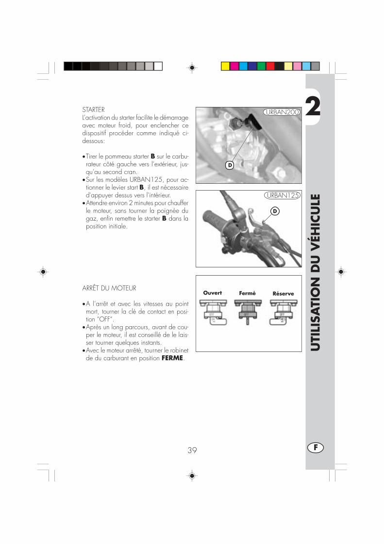
2
UTI
LISA
TIO
N D
U V
ÉHIC
ULE
39 F
STARTERL’activation du starter facilite le démarrageavec moteur froid, pour enclencher cedispositif procéder comme indiqué ci-dessous:
•Tirer le pommeau starter B sur le carbu-rateur côté gauche vers l’extérieur, jus-qu’au second cran.
•Sur les modèles URBAN125, pour ac-tionner le levier start B, il est nécessaired'appuyer dessus vers l'intérieur.
•Attendre environ 2 minutes pour chaufferle moteur, sans tourner la poignée dugaz, enfin remettre le starter B dans laposition initiale.
ARRÊT DU MOTEUR
•A l’arrêt et avec les vitesses au pointmort, tourner la clé de contact en posi-tion “OFF“.
•Après un long parcours, avant de cou-per le moteur, il est conseillé de le lais-ser tourner quelques instants.
•Avec le moteur arrêté, tourner le robinetde du carburant en position FERME.
Ouvert Fermé Réserve
D
D
URBAN125
URBAN200

2
UTI
LISA
TIO
N D
U V
ÉHIC
ULE
40F
APPROVISIONNEMENT EN CARBU-RANT
•Couper le moteur•Retirer le bouchon A.
Nota:La capacité du réservoir est d’environ 6litres dont 1 de réserve.
Attention:Le carburant est extrêmement inflamma-ble.
D’éventuels débordements du carburantsur le châssis ou sur d’autres parties dela moto doivent être éliminées immédia-tement.
Avant de prendre du carburant, arrêterle moteur.
Eviter de faire sortir du carburant du ré-servoir pendant le ravitaillement.
Ne pas s’approcher du goulot du réser-voir avec flammes libres ou cigarettesallumées.
Eviter aussi d’inhaler les vapeurs toxiques.
A
3
CO
NTR
ÔLE
S ET
EN
TRET
IEN
41 F
TABLE DES MATIÈRES
CHAP. 3 CONTRÔLES ET ENTRETIEN
Huile moteur et filtre à huile
Tuyau de récupération des fumées
Liquide de frein, purge du circuit
Huile de fourche
Filtre à air
Bougie
Freins: avant, arrière
Batterie
Dépose de la carrosserie
Notes pour le trial
Nettoyage du véhicule et contrôles
Entretien programmé
Longue inactivité du véhicule
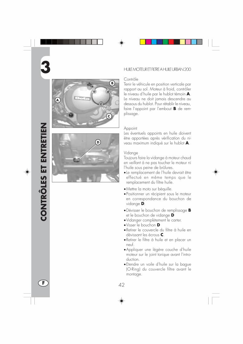
3
CO
NTR
ÔLE
S ET
EN
TRET
IEN
42F
HUILE MOTEUR ET FILTRE A HUILE URBAN 200
ContrôleTenir le véhicule en position verticale parrapport au sol. Moteur à froid, contrôlerle niveau d’huile par le hublot témoin A.Le niveau ne doit jamais descendre audessous du hublot. Pour rétablir le niveau,faire l’appoint par l’embout B de rem-plissage.
AppointLes éventuels appoints en huile doiventêtre apportées après vérification du ni-veau maximum indiqué sur le hublot A.
VidangeToujours faire la vidange à moteur chauden veillant à ne pas toucher le moteur nil’huile sous peine de brûlures.• Le remplacement de l’huile devrait êtreef fectué en même temps que leremplacement du filtre huile.
•Mettre la moto sur béquille.•Positionner un récipient sous le moteuren correspondance du bouchon devidange D.
•Dévisser le bouchon de remplissage Bet le bouchon de vidange D
•Vidanger complètement le carter.•Visser le bouchon D•Retirer le couvercle du filtre à huile endévissant les écrous C.
•Retirer le filtre à huile et en placer unneuf.
•Appliquer une légère couche d’huilemoteur sur le joint torique avant l’intro-duction.
•Etendre un voile d’huile sur la bague(O-Ring) du couvercle filtre avant lemontage.
B
A
C
D
3
CO
NTR
ÔLE
S ET
EN
TRET
IEN
43 F
•Remettre le couvercle du filtre à huile aprèsmontage du ressort et du joint torique etserrer les 3 écrous de fixation C.
• Introduire la juste quantité d’huile:- changement huile 850 ml- avec changement filtre 950 ml- révision 1300 ml
•Refermer le bouchon de chargement B.
•Démarrer le moteur en laissant tournerquelques minutes avant de le couper.
•Arrêter le moteur et attendre environ uneminute, enfin contrôler le niveau etéventuellement remplir à ras bord, sansjamais dépasser le niveau max indiquésur le hublot A.
Nota:lorsque les 1000 premiers kilomètre deparcours ont été effectués, vidanger l’huilemoteur. Les vidanges suivantes s’effectuenttous les 5000 km15 mois,(voir tableaupage 57), en utilisant les lubrifiants con-seillés à page 37.Pour le filtre à huile en revanche, le pre-mier changement a lieu en même tempsque la vidange. Les remplacements sui-vants tous les 10.000 km (30 mois).
Attention:Evacuer l’huile usée dans le respect desnormes en vigueur.
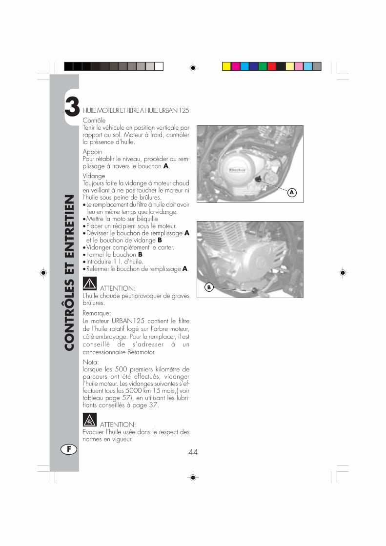
3
CO
NTR
ÔLE
S ET
EN
TRET
IEN
44F
HUILE MOTEUR ET FILTRE A HUILE URBAN 125ContrôleTenir le véhicule en position verticale parrapport au sol. Moteur à froid, contrôlerla présence d’huile.AppoinPour rétablir le niveau, procéder au rem-plissage à travers le bouchon A.VidangeToujours faire la vidange à moteur chauden veillant à ne pas toucher le moteur nil’huile sous peine de brûlures.• Le remplacement du filtre à huile doit avoirlieu en même temps que la vidange.
•Mettre la moto sur béquille•Placer un récipient sous le moteur.•Dévisser le bouchon de remplissage Aet le bouchon de vidange B
•Vidanger complètement le carter.•Fermer le bouchon B• Introduire 1 l. d'huile.•Refermer le bouchon de remplissage A.
ATTENTION:L’huile chaude peut provoquer de gravesbrûlures.
Remarque:Le moteur URBAN125 contient le filtrede l’huile rotatif logé sur l’arbre moteur,côté embrayage. Pour le remplacer, il estconseil lé de s’adresser à unconcessionnaire Betamotor.Nota:lorsque les 500 premiers kilomètre deparcours ont été effectués, vidangerl’huile moteur. Les vidanges suivantes s’ef-fectuent tous les 5000 km 15 mois,( voirtableau page 57), en utilisant les lubri-fiants conseillés à page 37.
ATTENTION:Evacuer l’huile usée dans le respect desnormes en vigueur.
A
B

3
CO
NTR
ÔLE
S ET
EN
TRET
IEN
45 F
TUYAU DE RÉCUPÉRATION DES FUMÉES
Le tuyau récolte gaz A est placé sur lecôté gauche de la moto près de l’amor-tisseur, il sort de la partie inférieure de lamanchon admission et il récolte les gaz pro-duits par l’huile moteur. En présenced’huile à l’intérieur du tuyau, celui-ci doitêtre vidé, en retirant le bouchon sur l’ex-trémité inférieure et en faisant couler l’huileou le mélange huile-essence dans un ré-cipient. Evacuer l’huile dans le respectdes normes en vigueur.Nota:Vider ce tuyau tous les 3000 km.
ATTENTION:Evacuer l’huile usée dans le respect desnormes en vigueur.
LIQUIDE DE FREIN, PURGE DU CIRCUITFrein avantContrôler par le voyant de niveau B, la pré-sence de liquide. Le niveau minimum de li-quide ne doit jamais être en dessous du re-père sur le témoin B. Pour rétablir le niveau,faire l’appoint après avoir dévissé les deuxvis C et soulevé le bouchon D.Frein arrièreContrôler à l’aide du témoin de niveau E laprésence de l’huile. Le niveau minimum del’huile ne doit jamais être inférieur au pointde repère sur le témoin de niveau E. Pourrétablir le niveau procéder au remplissageen dévissant les deux vis F, en soulevant lebouchon G et en versant l’huile.
ATTENTION:En cas de faible résistance du levier de frein,l’anomalie peut être causée par une bulled’air dans le circuit de freinage. Il est néces-saire de s’adresser au plus tôt à un répara-teur agréé. Dans ce cas effectuer la purgede l’air du circuit du frein.Nota:Pour les vidanges, respecter le tableau àpage 57 et utiliser les lubrifiants conseillés àpage 37.
A
D
C
B
F
EG
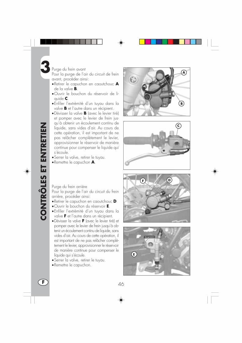
3
CO
NTR
ÔLE
S ET
EN
TRET
IEN
46F
Purge du frein avantPour la purge de l’air du circuit de freinavant, procéder ainsi:•Retirer le capuchon en caoutchouc Ade la valve B.
•Ouvrir le bouchon du réservoir de li-quide C.
•Enfiler l’extrémité d’un tuyau dans lavalve B et l’autre dans un récipient.
•Dévisser la valve B (avec le levier tiré)et pomper avec le levier de frein jus-qu’à obtenir un écoulement continu deliquide, sans vides d’air. Au cours decette opération, il est important de nepas relâcher complètement le levier,approvisionner le réservoir de manièrecontinue pour compenser le liquide quis’écoule.
•Serrer la valve, retirer le tuyau.•Remettre le capuchon A.
Purge du frein arrièrePour la purge de l’air du circuit du freinarrière, procéder ainsi:•Retirer le capuchon en caoutchouc D•Ouvrir le bouchon du réservoir E.•Enfiler l’extrémité d’un tuyau dans lavalve F et l’autre dans un récipient.
•Dévisser la valve F (avec le levier tiré) etpomper avec le levier de frein jusqu’à ob-tenir un écoulement continu de liquide, sansvides d’air. Au cours de cette opération, ilest important de ne pas relâcher complè-tement le levier, approvisionner le réservoirde manière continue pour compenser leliquide qui s’écoule.
•Serrer la valve, retirer le tuyau.•Remettre le capuchon.
DF
A
B
C
E
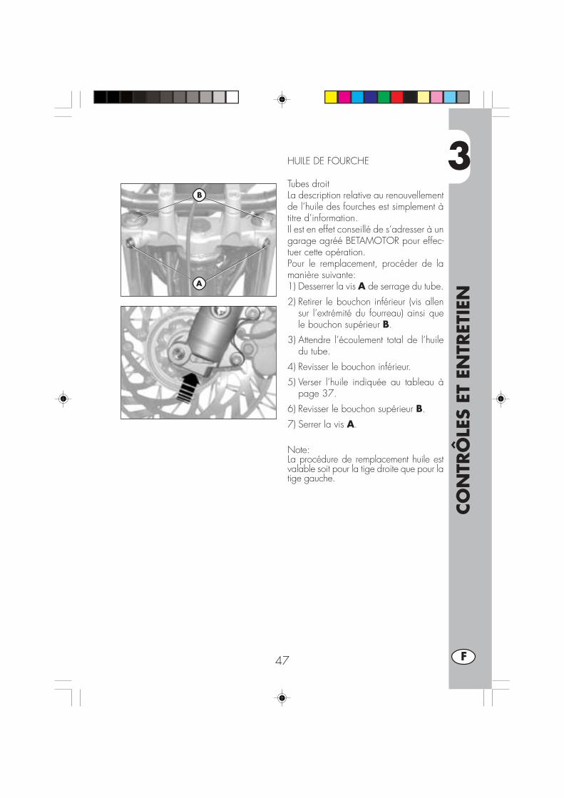
3
CO
NTR
ÔLE
S ET
EN
TRET
IEN
47 F
HUILE DE FOURCHE
Tubes droitLa description relative au renouvellementde l’huile des fourches est simplement àtitre d’information.Il est en effet conseillé de s’adresser à ungarage agréé BETAMOTOR pour effec-tuer cette opération.Pour le remplacement, procéder de lamanière suivante:1) Desserrer la vis A de serrage du tube.
2) Retirer le bouchon inférieur (vis allensur l’extrémité du fourreau) ainsi quele bouchon supérieur B.
3) Attendre l’écoulement total de l’huiledu tube.
4) Revisser le bouchon inférieur.
5) Verser l’huile indiquée au tableau àpage 37.
6) Revisser le bouchon supérieur B.
7) Serrer la vis A.
Note:La procédure de remplacement huile estvalable soit pour la tige droite que pour latige gauche.
A
B
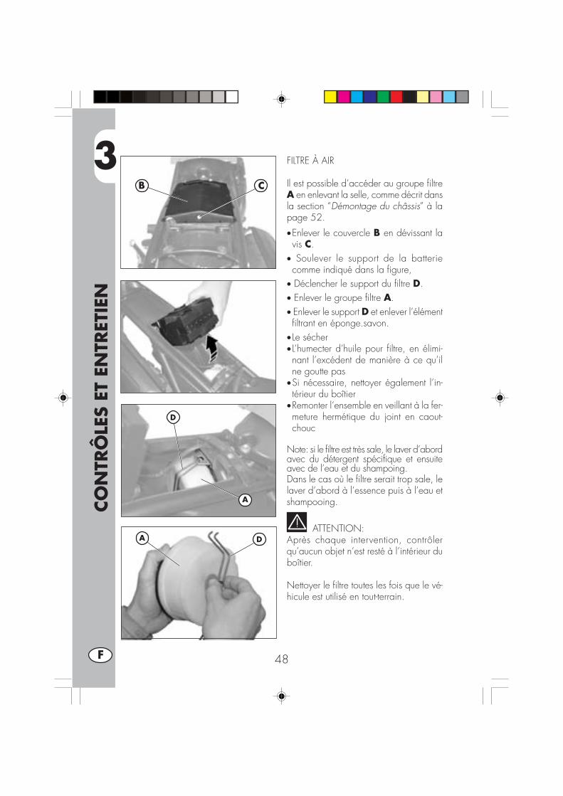
3
CO
NTR
ÔLE
S ET
EN
TRET
IEN
48F
FILTRE À AIR
Il est possible d’accéder au groupe filtreA en enlevant la selle, comme décrit dansla section “Démontage du châssis” à lapage 52.
•Enlever le couvercle B en dévissant lavis C.
• Soulever le support de la batteriecomme indiqué dans la figure,
• Déclencher le support du filtre D.• Enlever le groupe filtre A.• Enlever le support D et enlever l’élémentfiltrant en éponge.savon.
• Le sécher• L’humecter d’huile pour filtre, en élimi-nant l’excédent de manière à ce qu’ilne goutte pas
•Si nécessaire, nettoyer également l’in-térieur du boîtier
•Remonter l’ensemble en veillant à la fer-meture hermétique du joint en caout-chouc
Note: si le filtre est très sale, le laver d’abordavec du détergent spécifique et ensuiteavec de l’eau et du shampoing.Dans le cas où le filtre serait trop sale, lelaver d’abord à l’essence puis à l’eau etshampooing.
ATTENTION:Après chaque intervention, contrôlerqu’aucun objet n’est resté à l’intérieur duboîtier.
Nettoyer le filtre toutes les fois que le vé-hicule est utilisé en tout-terrain.
D
A
B C
DA

3
CO
NTR
ÔLE
S ET
EN
TRET
IEN
49 F
BOUGIE
Effectuer l’opération en utili-sant des gants de protectionpour éviter des brûlures.
Une bougie en bon état contribue à ladiminution de la consommation et auparfait fonctionnement du moteur. Il estpréférable de retirer la bougie lorsque lemoteur est en température (évidemmentcoupé) car les dépôts de calamine et lacoloration de l’isolant fournissent des in-dications importantes sur la carburation,sur la lubrification et sur l’état général dumoteurEn effet si la coloration de l’isolement estblanche, la carburation pourrait être trop“maigre”, si vice-versa la coloration estverte la carburation pourrait être considé-rée trop “riche”. Une carburation correctedevrait être mise en évidence par la colo-ration noisette.Pour ce contrôle, il suffit d’enlever la cosseet de dévisser la bougie à l’aide de laclé fournie.Nettoyer soigneusement les électrodes enutilisant une brosse métallique. Soufflerla bougie à l’air comprimé pour éviterque les résidus éventuels puissent péné-trer dans le moteur.Mesurer l’écartement des électrodes avecun calibre d’épaisseur, il doit être de 0,6- 0,7 mm, dans le cas où il ne corres-ponde pas à cette valeur, il est possiblede corriger en pliant l’électrode de masse.
Vérifier qu’il n’y a pas de fissures sur l’iso-lant ou d’électrodes corrodées, dans cescas, il faut la remplacer immédiatement.
Nota:Effectuer le contrôle en respectant les in-dications du tableau à page 57.
Nota:Lubrifier le filetage de la bougie et (mo-teur à froid), la visser à la main jusqu’àla butée puis la bloquer avec la clé.
Nota:Il est recommandé d’utiliser toujours desbougies:URBAN 200 = NGK DR8 EAURBAN 125 = NGK CR7 HSA
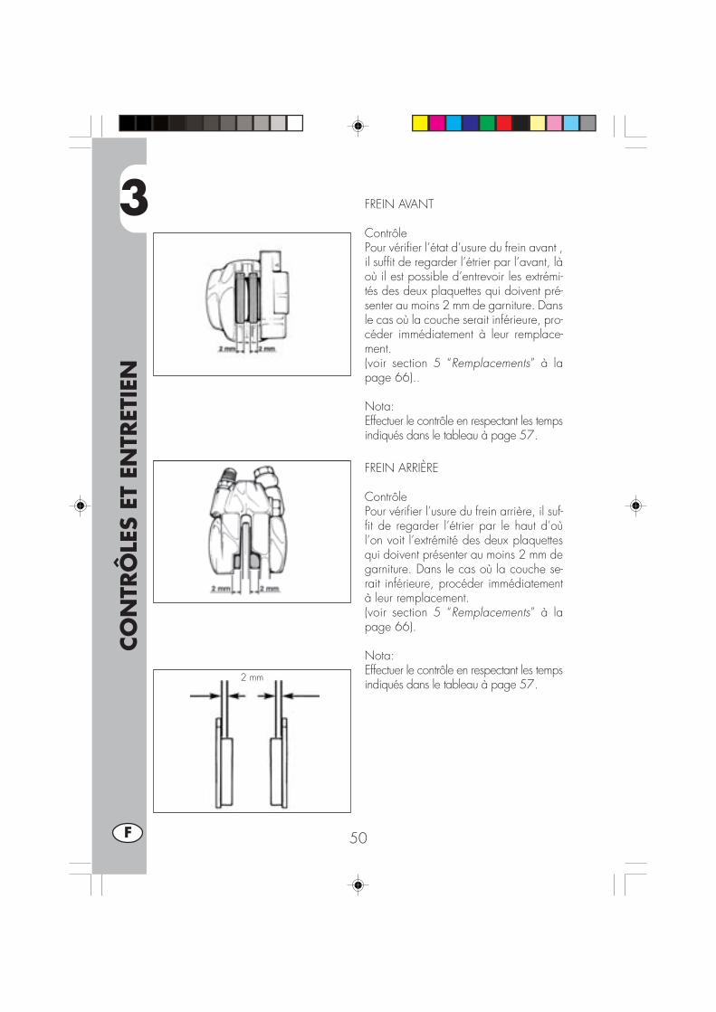
3
CO
NTR
ÔLE
S ET
EN
TRET
IEN
50F
2 mm
FREIN AVANT
ContrôlePour vérifier l’état d’usure du frein avant ,il suffit de regarder l’étrier par l’avant, làoù il est possible d’entrevoir les extrémi-tés des deux plaquettes qui doivent pré-senter au moins 2 mm de garniture. Dansle cas où la couche serait inférieure, pro-céder immédiatement à leur remplace-ment.(voir section 5 “Remplacements” à lapage 66)..
Nota:Effectuer le contrôle en respectant les tempsindiqués dans le tableau à page 57.
FREIN ARRIÈRE
ContrôlePour vérifier l’usure du frein arrière, il suf-fit de regarder l’étrier par le haut d’oùl’on voit l’extrémité des deux plaquettesqui doivent présenter au moins 2 mm degarniture. Dans le cas où la couche se-rait inférieure, procéder immédiatementà leur remplacement.(voir section 5 “Remplacements” à lapage 66).
Nota:Effectuer le contrôle en respectant les tempsindiqués dans le tableau à page 57.

3
CO
NTR
ÔLE
S ET
EN
TRET
IEN
51 F
BATTERIE
Vérifier la charge de la batterie avec unvoltmètre en mesurant la tension avec labatterie au repos: moteur coupé. Le vol-tage ne doit pas être inférieur à 12,8 V.Il n'est pas nécessaire de contrôler leniveau de l'électrolyte ni de remplir avecde l'eau.Maintenir les pôles de la batterie pro-pres et si nécessaire lubrifier ceux-ci àl'aide de graisses sans acides.

3
CO
NTR
ÔLE
S ET
EN
TRET
IEN
52F
DEMONTAGE DU CHASSIS
Pour effectuer aisément les contrôles oules opérations d’entretien il faut enlevercertaines pièces du châssis.
ATTENTION:Le remontage erroné de ces pièces peutcauser leur détachement soudain pendantla marche ce qui entraîne la perte decontrôle de la moto.
Démontage de la sellePour enlever la selle, il suffit d’enlever lesdeux vis A, la fixation B et la fixation Csous la selle.
Remarque :En enlevant la selle, on enlève égalementle garde-boue.Pour séparer les deux éléments, il fautenlever les trois vis D.
Démontage de la couverture duréservoirPour démonter les couvertures du réser-voir E, il faut :• Dévisser les vis Fsur le réservoir.• Dévisser les deux fixations G, situées à
l’avant du véhicule.• Enlever les couvertures du réservoir E.
F
E
G
A
B
C
D

3
CO
NTR
ÔLE
S ET
EN
TRET
IEN
53 F
Démontage du réservoir de car-burantAprès avoir enlevé la selle, dévisser lavis H de fixation du réservoir auchâssis, enlever le tuyau du robinet ducarburant et enlever le réservoir en lefaisant glisser vers l’arrière.
Démontages joues latéralesPour enlever les deux joues latérales Lplacées sous le réservoir sur les deux côtésde la moto il est suffisant d’enlever lesdeux vis I.
Démontage support groupe op-tique avantDévisser les deux vis de fixation du phareN, débrancher les connexions électriquesdu phare, puis dévisser les deux vis Mde fixation du châssis du garde-boue.
H
L
I
N
M
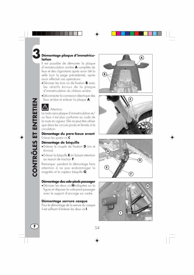
3
CO
NTR
ÔLE
S ET
EN
TRET
IEN
54F
Démontage plaque d’immatricu-lationIl est possible de démonter la plaqued’immatriculation arrière A complète defeux et des clignotants après avoir ôté laselle (voir la page précédente); aprèsavoir effectué ces opérations:•Dévisser les trois vis de fixation B avecles relatifs écrous de la plaqued’immatriculation du châssis arrière.
•Déconnecter la connexion électrique desfeux arrière et enlever la plaque A.
Attention:La moto sans plaque d’immatriculation et/ou feux n’est plus conforme au code dela route en vigueur. Elle ne peut être utiliserque dans les circuits privés et fermés à lacirculation.Démontage du pare-boue avantEnlever les quatre vis CDémontage de béquille•Enlever le couple de fixation D (vis etécrous).
•Enlever la béquille E en faisant attentionau ressort de traction F.
Remarque: pendant le démontage faireattention à ne pas endommager lamagnéto et le capteur béquille G.
Démontage des cale-pieds passager•Dévisser les deux vis Hindiquées sur lafigure et déposer le cale-pied passageravec le support d’ancrage sur cadre.
Démontage serrure casquePour le démontage de la serrure du casqueil est suffisant d’enlever les deux vis I.
A
B
E
D
F
G
H
I
C
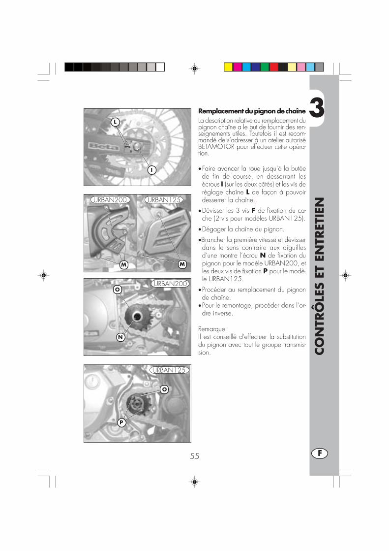
3
CO
NTR
ÔLE
S ET
EN
TRET
IEN
55 F
Remplacement du pignon de chaîneLa description relative au remplacement dupignon chaîne a le but de fournir des ren-seignements utiles. Toutefois il est recom-mandé de s’adresser à un atelier autoriséBETAMOTOR pour effectuer cette opéra-tion.
•Faire avancer la roue jusqu’à la butéede fin de course, en desserrant lesécrous I (sur les deux côtés) et les vis deréglage chaîne L de façon à pouvoirdesserrer la chaîne..
•Dévisser les 3 vis F de fixation du ca-che (2 vis pour modèles URBAN125).
•Dégager la chaîne du pignon.
•Brancher la première vitesse et dévisserdans le sens contraire aux aiguillesd’une montre l’écrou N de fixation dupignon pour le modèle URBAN200, etles deux vis de fixation P pour le modè-le URBAN125.
•Procéder au remplacement du pignonde chaîne.
•Pour le remontage, procéder dans l’or-dre inverse.
Remarque:Il est conseillé d'effectuer la substitutiondu pignon avec tout le groupe transmis-sion.
I
M
O
N
L
M
P
O
URBAN200 URBAN125
URBAN200
URBAN125

3
CO
NTR
ÔLE
S ET
EN
TRET
IEN
56F
NETTOYAGE DU VÉHICULE ET CONTRÔLES
Pour ramollir la saleté et la boue accumulées sur les peintures, utiliser un jet d’eau àbasse pression. Une fois ramollis, la boue et la saleté doivent être enlevées avec uneéponge douce pour carrosserie imprégnée de beaucoup d’eau et shampooing (2-4% de shampooing dans l’eau). Rincer ensuite abondamment à l’eau et essuyeravec une peau de chamois. Pour l’extérieur du moteur, utiliser du pétrole avec pin-ceaux et chiffons propres. Le pétrole est nocif pour les peintures. Il est rappelé que lelustrage éventuel avec des cires au silicone doit toujours être précédé d’un lavage.
Les détergents polluent les eaux. Aussi, le lavage du véhicule doit s’effectuerdans un endroit équipé pour la récupération et l’épuration des liquides delavage.
Le lavage ne doit jamais avoir lieu au soleil, en particulier l’été lorsque lacarrosserie est encore chaude et que le shampooing sèche avant le rinçage
pouvant provoquer des dommages à la peinture. Ne jamais utiliser de chiffon impré-gnés d’essence ou de mazout pour le lavage des peintures ou des plastiques car ilperdent leur brillant et les caractéristiques mécaniques des matériaux se détériorent.
L’emploi de systèmes d’hydronettoyage peut endommager l’outillage; il estdonc conseillé de ne pas adresser le jet d’eau sur les composants électriques,en particulier sur l’écran LCD.
CONTRÔLES APRÈS LE NETTOYAGEAprès le nettoyage de la moto, il est préférable de:•Nettoyer le filtre à air (procéder comme décrit à page 48)•Graisser la chaîne.
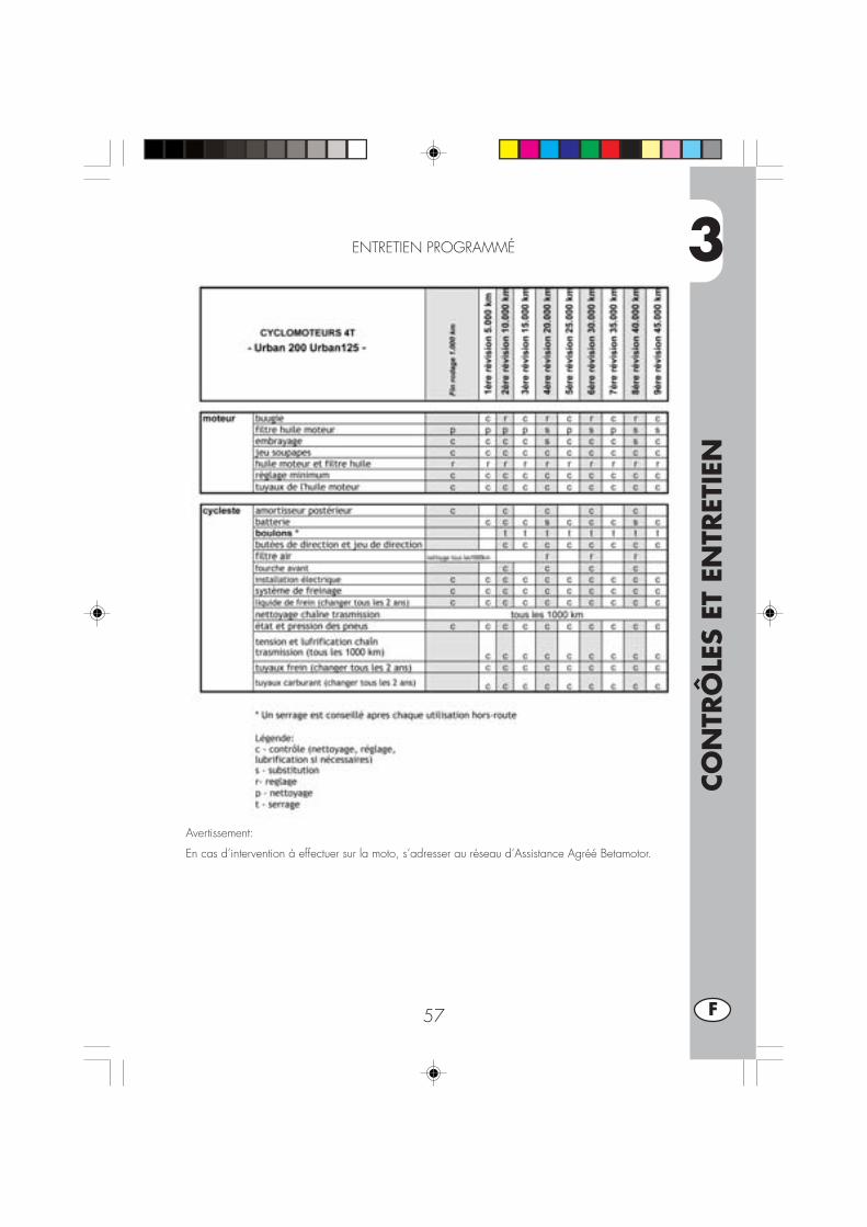
3
CO
NTR
ÔLE
S ET
EN
TRET
IEN
57 F
ENTRETIEN PROGRAMMÉ
Avertissement:
En cas d’intervention à effectuer sur la moto, s’adresser au réseau d’Assistance Agréé Betamotor.

3
CO
NTR
ÔLE
S ET
EN
TRET
IEN
58F
LONGUE INACTIVITÉ DU VÉHICULE
En prévision d’une longue période d’inactivité du véhicule, par exemple durant lasaison d’hiver, il est nécessaire de prendre quelques mesures simples qui garantis-sent un bon maintien.•Effectuer un nettoyage soigné de toutesles parties du véhicule ;
•Réduire la pression des pneumatiquesd’environ 30% en les maintenant si pos-sible soulevés du sol.
•Retirer la bougie et verser dans l’orificequelques gouttes d’huile moteur. Fairetourner le moteur de quelques tours avecle levier de kick (si prévu), revisser labougie.
•Couvrir d’un voile d’huile ou de siliconespray, les parties non peintes, à l’ex-ception des parties en caoutchouc etdes freins.
•Déposer la batterie pour la conserverdans un endroit sec et la charger unefois par mois.
•Couvrir le véhicule avec une bâche pourla poussière.
•Vidanger la cuve du carburateur enagissant sur la vis A. Le carburant chasséde la cuve dans un tuyau prévu à ceteffet, doit être récupéré dans un récipient et versé dans le réservoir sans le disper-ser dans l’environnement.
•Serrer la vis.
APRÈS UNE LONGUE PÉRIODE D’INACTIVITÉ
•Remettre la batterie en place.•Rétablir la pression des pneus.•Contrôler le serrage de toutes les vis ayant une certaine importance du point devue mécanique.
Nota:Le contrôle du serrage des vis doit être renouvelé régulièrement.
A
A
URBAN200
URBAN125

4
RÉG
LAG
ES
59 F
TABLE DES MATIÈRES
CHAP. 4 RÉGLAGES
Réglage des freins
Réglage de l’embrayage
Réglage du ralenti
Réglage du jeu à la poignée des gaz
Contrôle et réglage du jeu à la direction
Tension de la chaîne
Faisceau lumineux
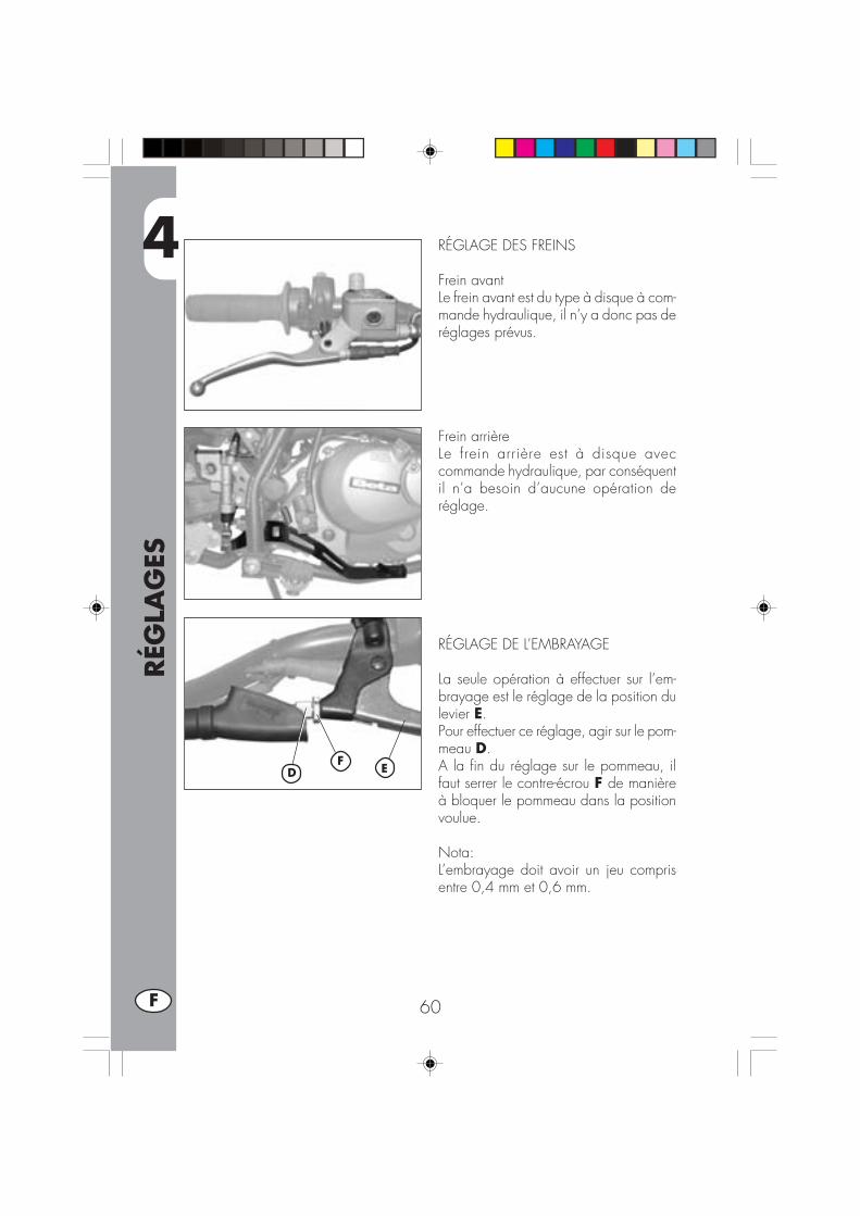
4
RÉG
LAG
ES
60F
RÉGLAGE DES FREINS
Frein avantLe frein avant est du type à disque à com-mande hydraulique, il n’y a donc pas deréglages prévus.
Frein arrièreLe frein arrière est à disque aveccommande hydraulique, par conséquentil n’a besoin d’aucune opération deréglage.
RÉGLAGE DE L’EMBRAYAGE
La seule opération à effectuer sur l’em-brayage est le réglage de la position dulevier E.Pour effectuer ce réglage, agir sur le pom-meau D.A la fin du réglage sur le pommeau, ilfaut serrer le contre-écrou F de manièreà bloquer le pommeau dans la positionvoulue.
Nota:L’embrayage doit avoir un jeu comprisentre 0,4 mm et 0,6 mm.
FD E

4
RÉG
LAG
ES
61 F
RÉGLAGE DU RALENTI URBAN 200Pour effectuer correctement cette opéra-tion, il est conseillé de la réaliser à mo-teur chaud, en branchant un compte-tourélectronique au câble de bougie. Inter-venir ensuite sur la vis de réglage A etétalonner le ralenti (régime moteur 1400± 100).
RÉGLAGE DU RALENTI URBAN 125Pour effectuer correctement cette opéra-tion, il est conseillé de la réaliser à mo-teur chaud, en branchant un compte-tourélectronique au câble de bougie.Intervenir ensuite à l'aide d'un tournevissur la vis de réglage C en calibrant leminimum sur 1900 tours.
REGLAGE DU DEBIT D’ESSENCEURBAN125/200Pour régler le débit d'essence, agir sur lavis D en la desserrant d'un tour et demi àpartir de la positions de fermeture totale.Tarage d’usine du réglage: de la positiontout fermé (complètement tourné vers ladroit), dévissez le reglage de 1,5 tours.
RÉGLAGE DU JEU A LA POIGNÉE DESGAZSi la commande d’accélérateur présenteune course à vide supérieure à 3 mmmesurée sur le bord de la poignée, il fautfaire le réglage en agissant sur la vis deréglage B de la poignée.
A
CD
D
B
URBAN200
URBAN125

4
RÉG
LAG
ES
62F
CONTRÔLE ET RÉGLAGE DU JEU ALA DIRECTION
Vérifier périodiquement le jeu à la di-rection en faisant jouer la fourche enavant et en arrière comme le montre lafigure. En cas de jeu, procéder au ré-glage en opérant de la manière sui-vante:
•Dévisser les 4 vis A•Extraire le guidon B en faisant atten-tion aux cavaliers C
•Desserrer l’écrou D• Desserrer les 2 vis F,
•Compenser le jeu en intervenant surl’écrou à créneau E
Pour le blocage, procéder de manièreinverse.
Note:Un réglage correct en plus de ne paslaisser de jeu, ne doit pas provoquerde durcissement ou de points durs à larotation du guidon. Vérifier le sens demontage des cavaliers qui peut modi-fier l’assise du guidon.Note:Est recomandé de s’adresser à un ate-lier autorisé Betamotor pour effectuercette opération.
B
D
E C
A
F F

4
RÉG
LAG
ES
63 F
TENSION DE LA CHAINE
Per una più lunga durata della catena ditrasmissione è opportuno controllareperiodicamente la sua tensione.Tenerla sempre pulita dalla sporciziadepositata e lubrificarla.Se il gioco della catena supera i 20 mmprocedere al suo tensionamento.
•Desserrer le écrou A sur le deux brasde la fourche
•Desserrer l’écrou C sur les deux bras dela fourche
•Agir sur l’écrou B jusqu’à obtenir latension de la chaîne requise
•Procéder de la même façon pour l’écrouB placé sur l’autre bras de la fourchejusqu’à obtenir l’alignement parfait dela roue
•Serrer les écrous B et A sur les deuxbras de la fourche.
20 mm
B
C A
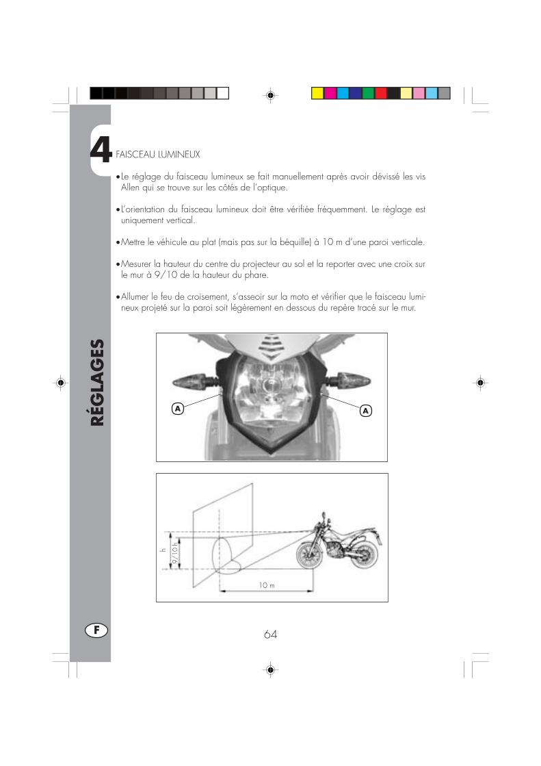
4
RÉG
LAG
ES
64F
FAISCEAU LUMINEUX
• Le réglage du faisceau lumineux se fait manuellement après avoir dévissé les visAllen qui se trouve sur les côtés de l’optique.
• L’orientation du faisceau lumineux doit être vérifiée fréquemment. Le réglage estuniquement vertical.
•Mettre le véhicule au plat (mais pas sur la béquille) à 10 m d’une paroi verticale.
•Mesurer la hauteur du centre du projecteur au sol et la reporter avec une croix surle mur à 9/10 de la hauteur du phare.
•Allumer le feu de croisement, s’asseoir sur la moto et vérifier que le faisceau lumi-neux projeté sur la paroi soit légèrement en dessous du repère tracé sur le mur.
9/10
h
10 m
h
AA
5
REM
PLA
CEM
ENTS
65 F
TABLE DES MATIÈRES
CHAP. 5 REMPLACEMENTS
Remplacement des plaquettes de frein
Remplacement de l’ampoule de phare avant
Remplacement de l’ampoule de phare arrière
Remplacement des ampoules des clignotants
Caractéristiques ampoules
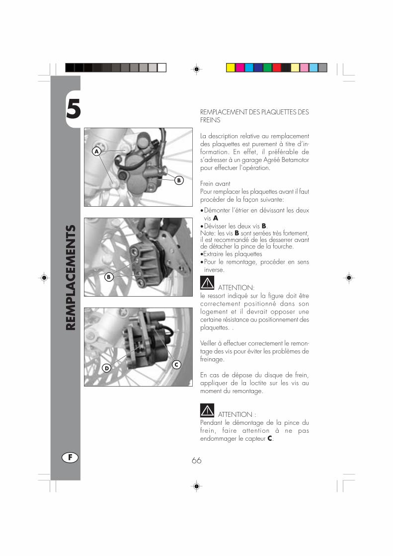
5
REM
PLA
CEM
ENTS
66F
REMPLACEMENT DES PLAQUETTES DESFREINS
La description relative au remplacementdes plaquettes est purement à titre d’in-formation. En effet, il préférable des’adresser à un garage Agréé Betamotorpour effectuer l’opération.
Frein avantPour remplacer les plaquettes avant il fautprocéder de la façon suivante:
•Démonter l’étrier en dévissant les deuxvis A
•Dévisser les deux vis B.Note: les vis B sont serrées très fortement,il est recommandé de les desserrer avantde détacher la pince de la fourche.•Extraire les plaquettes•Pour le remontage, procéder en sensinverse.
ATTENTION:le ressort indiqué sur la figure doit êtrecorrectement positionné dans sonlogement et il devrait opposer unecertaine résistance au positionnement desplaquettes. .
Veiller à effectuer correctement le remon-tage des vis pour éviter les problèmes defreinage.
En cas de dépose du disque de frein,appliquer de la loctite sur les vis aumoment du remontage.
ATTENTION :Pendant le démontage de la pince dufrein, faire attention à ne pasendommager le capteur C.
CD
A
B
B

5
REM
PLA
CEM
ENTS
67 F
FREIN ARRIEREFrein arrièrePour remplacer les plaquettes arrière ilfaut procéder de la façon suivante:
•Enlever l’élément de sécurité A•Dévisser le doigt de support desplaquettes B
•Enlever les plaquettes C.
•Pour le remontage procéder dans le sensinverse, faisant bien attention aurepositionnement correct des plaquettesdans leur siège
NOTE:Pour le remplacement des plaquettes ilest conseillé de s’adresser à un atelierautorisé BETAMOTOR.
A
B
C
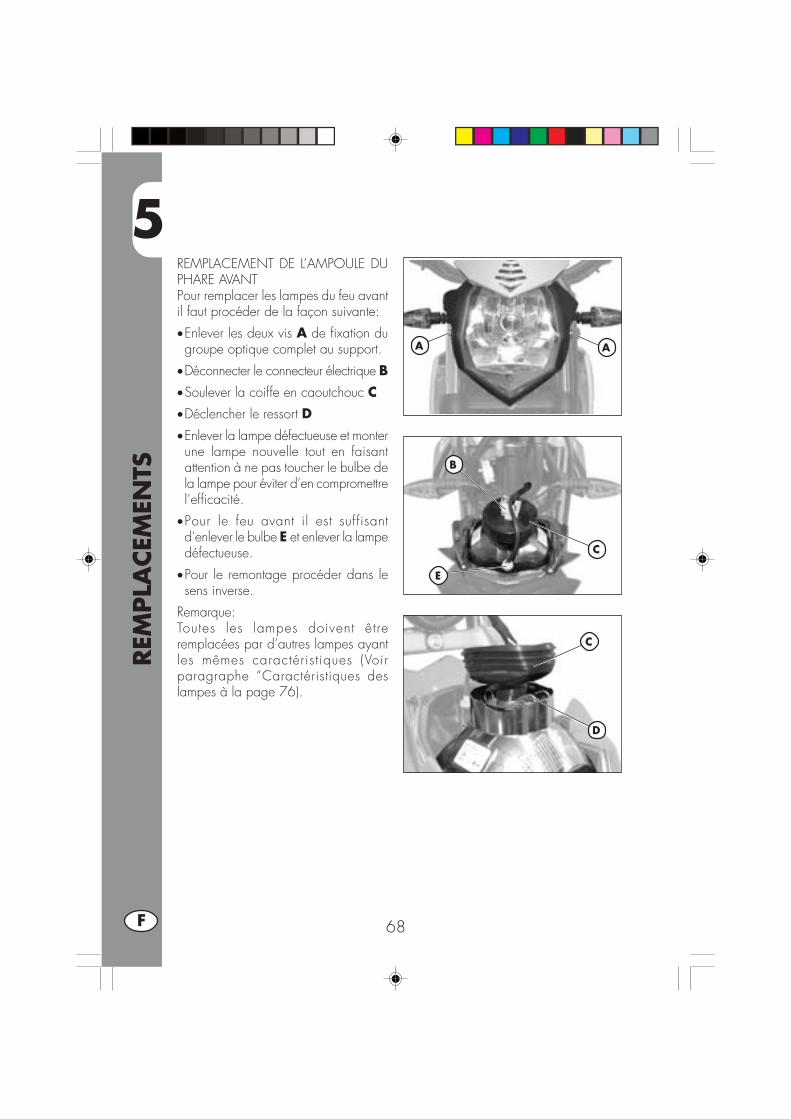
5
REM
PLA
CEM
ENTS
68F
REMPLACEMENT DE L’AMPOULE DUPHARE AVANTPour remplacer les lampes du feu avantil faut procéder de la façon suivante:
•Enlever les deux vis A de fixation dugroupe optique complet au support.
•Déconnecter le connecteur électrique B•Soulever la coiffe en caoutchouc C•Déclencher le ressort D
•Enlever la lampe défectueuse et monterune lampe nouvelle tout en faisantattention à ne pas toucher le bulbe dela lampe pour éviter d’en compromettrel’efficacité.
•Pour le feu avant il est suffisantd’enlever le bulbe E et enlever la lampedéfectueuse.
•Pour le remontage procéder dans lesens inverse.
Remarque:Toutes les lampes doivent êtreremplacées par d’autres lampes ayantles mêmes caractérist iques (Voirparagraphe “Caractéristiques deslampes à la page 76).
B
C
C
D
E
AA

5
REM
PLA
CEM
ENTS
69 F
REMPLACEMENT DE L’AMPOULE DUPHARE ARRIÈRE
Pour remplacer le groupe feu arrière A ilfaut procéder de la façon suivante:•Enlever la plaque d’immatriculationcomme indiqué dans la section“Démontage du châssis” à la page 60
•Déconnecter toutes les connexionsélectriques
•Dévisser les deux vis B placées sous legarde-boue
•Enlever le groupe feu A défectueux,remplacer le groupe feu défectueux parun groupe feu nouveau
•Pour le remontage procéder dans le sensinverse.
Remarque:Toutes les lampes doivent être remplacéespar d’autres lampes ayant les mêmescaractérist iques (Voir paragraphe“Caractéristiques des lampes à la page76).
REMPLACEMENT DES AMPOULE POURFEU PLAQUE POLICE
Pour remplacer la lampe de la plaqued’immatriculation il faut:•Dévisser la vis C•Enlever le transparent D•Enlever la lampe défectueuse du bulbeet la remplacer par une lampe nouvelle.
•Pour le remontage procéder dans le sensinverse.
Remarque:Toutes les lampes doivent être remplacéespar d’autres lampes ayant les mêmescaractéristiques (Voir paragraphe“Caractéristiques des lampes à la page 76).
A
B
CD
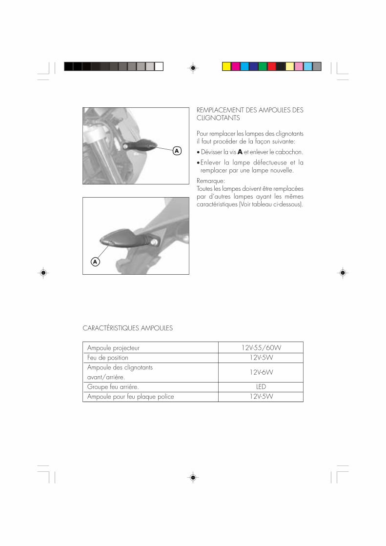
REMPLACEMENT DES AMPOULES DESCLIGNOTANTS
Pour remplacer les lampes des clignotantsil faut procéder de la façon suivante:
• Dévisser la vis A et enlever le cabochon.
•Enlever la lampe défectueuse et laremplacer par une lampe nouvelle.
Remarque:Toutes les lampes doivent être remplacéespar d’autres lampes ayant les mêmescaractéristiques (Voir tableau ci-dessous).
A
A
Ampoule projecteur 12V-55/60WFeu de position 12V-5WAmpoule des clignotantsavant/arriére.
12V-6W
Groupe feu arriére. LEDAmpoule pour feu plaque police 12V-5W
CARACTÉRISTIQUES AMPOULES
6
QU
E FA
IRE
EN C
AS
D’U
RG
ENCE
?
71 F
TABLE DES MATIÈRES
CHAP. 6 QUE FAIRE EN CAS D’URGENCE ?
INDEX ALPHABÉTIQUE

6
QU
E FA
IRE
EN C
AS
D’U
RG
ENCE
?
72F
PROBLÈME CAUSE
Le moteur ne démarrepas
REMÈDE
- Circuit d’alimentation encarburant obstrué (canalisations,réservoir d’essence, robinet)
- Filtre à air trop encrassé
- Le courant n’arrive pas à labougie
- Moteur noyé
Effectuer le nettoyage du circuit
Opérer comme indiqué à page 48
Effectuer le nettoyage ou le remplacementde la bougie. Si le problème persiste,s’adresser à un concessionnaire Agreé
Avec les gaz ouverts en grand, insisterquelques instants avec le démarrage.Si l’on obtient pas de résultat, il fautdémonter la bougie et la sécher
Le moteur à des ratés - Bougie avec écartement desélectrodes irrégulier
- Bougie encrassé
Rétablir l’écartement correct entre lesélectrodes
Nettoyer ou remplacer la bougie
Nettoyer ou remplacerla bougie
- Trop d’avance à l’allumage
- Présence de calamine à l’intérieurdu cylindre ou sur la bougie
Vérifier le calage de l’allumage
S’adresser à un concessionnaire agreé
Le moteur surchauffe etperd de la puissance
- Pot d’échappement partiellementobturé
- Lumière d’échappement obturée
- Retard à l’allumage
S’adresser à un concessionnaire agreé
S’adresser à un concessionnaire agreé
Vérifier le calage de l’allumage
Freinage insuffisant àl’avant
- Plaquettes usées
- Présence d’air ou d’humiditédans le circuit hydraulique
Opérer comme indiqué à page 66
Opérer comme indiqué à page 46
Freinage insuffisant àl’arrière
- Plaquettes usées
- Présence d’air ou d’humiditédans le circuit hydraulique
Opérer comme indiqué à page 66
Opérer comme indiqué à page 46
IND
EX A
LPH
ABÉT
IQU
E
73 F
Approvisionnement en carburant ............................................................. 40
Bougie ............................................................................................... 49
Caractéristiques techniques .................................................................... 24Clés .................................................................................................. 12Contacteur principal/verrouillage direction ............................................... 12Contrôles après le nettoyage .................................................................. 56Contrôles et entretien avant et après l’utilisation tout-terrain ........................... 36
Démarrage ......................................................................................... 38Direction: contrôle et réglage ................................................................. 62Données d’identification du véhicule .......................................................... 8
Entretien programmé ............................................................................. 57
Filtre à air ........................................................................................... 48Frein avant: contrôle et remplacement ................................................ 50, 66Frein arrière: contrôle et remplacement ............................................... 50, 67
Huile de fourche .................................................................................. 47Huile moteur: contrôle et vidange ...................................................... 42, 44
LCD................................................................................................... 14Lubrifiants et fluides conseillés ................................................................. 37
Purge des freins ................................................................................... 45
Recherche des pannes .......................................................................... 71Réglage de l’embrayage ....................................................................... 60Réglage des freins ................................................................................ 60Réglage du jeu à la poignée des gaz ...................................................... 61Réglage du ralenti ................................................................................ 61Remplacement des ampoules .................................................................. 68Rodage .............................................................................................. 37
Schéma électrique URBAN200 .............................................................. 30Schéma électrique URBAN125 .............................................................. 28Serrure du casque ................................................................................ 12
Tableau de bord et commandes .............................................................. 13Tension de la chaîne ............................................................................. 63


1 D
URBAN 125/200 cc
Vielen Dank für Ihr Vertrauen und viel Spaß.Mit dieser Bedienungsanleitung möchten wir Ihnen die notwendi-gen Informationen für einen richtigen Gebrauch und eine guteWartung Ihres Motorrads geben.
Alle Angaben zu Technik und Ausstattung sind unverbindlich. Die BetamotorS.p.A. behält sich das Recht vor, an ihren Fahrzeugmodellen jederzeit undohne Vorankündigung Änderungen und Verbesserungen vorzunehmen.

2D
HINWEIS
Wir raten Ihnen nach der ersten bzw. zweiten Betriebsstunde mitGeländefahrt alle Sicherheits-Anzugsmomente zu überprüfen unddabei besonders auf folgende Bauteile zu achten:
• Zahnkranz• Fußrastenbefestigung• Vorderer Bremssattel• Bremszange• Kennzeichenträger• Bügelbolzen für Lenkstangenbefestigung• Kotflügelbefestigung• Alle Schrauben und Bolzen am Motor• Alle Schrauben und Bolzen an den Stoßdämpfern• Radspeichen• Hinterer Rahmsen• Verkleidungen
HINWEIS
Für Arbeiten am Motorrad wenden Sie sich bitte an dasKundendienstnetz der Betamotor Vertragshändler.
INH
ALT
SVER
ZEI
CH
NIS
3 D
Hinweise zum Gebrauch des Fahrzeugs ..................................................... 5Umweltfreundliches Fahren ....................................................................... 5Sicheres Fahren ................................................................................. 246
KAPITEL 1 ALLGEMEINE ANGABEN............................................ 7Rahmen- und Motornummer ...................................................................... 8Auslieferung .......................................................................................... 8Zuladung .............................................................................................. 9Reifen .................................................................................................. 9Wichtigste Fahrzeugteile ....................................................................... 10Schlüssel ............................................................................................ 12Zünd-/ Lenkerschloß ............................................................................. 12Helmschloß ......................................................................................... 12Armaturenbrett und Bedienungselemente ................................................... 13Anleitung zum einstellen und betrib des kilometerzahlers .............................. 14Allgemeine technische Angaben ............................................................. 24Technische Angaben Motor URBAN1125 ................................................ 26Technische Angaben Motor URBAN1200 ................................................ 27Elektrische Schaltpläne URBAN1 125 ...................................................... 28Elektrische Schaltpläne URBAN1 200 ...................................................... 30Elektrische Anlage ................................................................................ 32Ventil AIS ............................................................................................ 34
KAPITEL 2 BEDIENUNGSVORSCHRIFTEN .................................. 35Kontrollen und Wartung vor und nach Einsatz im Gelände ........................... 36Empfohlene Schmiermittel und Flüssigkeiten ............................................... 37Einfahren ............................................................................................ 37Starten des Motors ............................................................................... 38Choke ............................................................................................... 39Abstellen des Motors ............................................................................ 39Tanken ............................................................................................... 40
KAPITEL 3 WARTUNG UND KONTROLLEN ............................... 41Motoröl und Ölfilter URBAN1200 ........................................................... 42Motoröl URBAN1125 .......................................................................... 44Leitung Öldampfsammlung ..................................................................... 45Bremsflüssigkeit, Entlüften der Bremsen ...................................................... 45Gabelöl ............................................................................................. 47Luftfilter ............................................................................................... 48Zündkerze .......................................................................................... 49Bremsen: Vorderradbremse, Hinterradbremse............................................. 50Batterie .............................................................................................. 51Ausbau von Karosserie- und anderen Fahrzeugteilen ................................... 52Fahrzeugpflege und Kontrollen ................................................................ 56Wartungsprogramm.............................................................................. 57Längeres Stilllegen des Fahrzeugs............................................................ 58
INH
ALT
SVER
ZEI
CH
NIS
4D
KAPITEL 4 EINSTELLUNGEN ..................................................... 59Einstellen der Bremsen ........................................................................... 60Einstellen der Kupplung ......................................................................... 60Leerlaufeinstellung ................................................................................ 61Einstellung Benzinfluss ........................................................................... 61Einstellen des Gaszuges ........................................................................ 61Kontrolle und Einstellen Lenkerspiels ......................................................... 62Spannen der Kette ................................................................................ 63Einstellen des Scheinwerfers ................................................................... 64
KAPITEL 5 AUSTAUSCHEN/ AUSWECHSELN VON TEILEN .......... 65Auswechseln der Bremsbeläge ............................................................... 66Auswechseln der Scheinwerferlampen ...................................................... 68Auswechseln der Rücklichtlampe ............................................................. 69Auswechseln Glühbirne Nummernschildbeleuchtung ................................... 69Auswechseln der Blinkerlampen .............................................................. 70Charakteristische Lampen ...................................................................... 70
KAPITEL 6 WAS IST IM NOTFALL ZU TUN ................................. 71
ALPHABETISCHES INHALTSVERZEICHNIS ................................................ 73

5 D
HINWEISE ZUM GEBRAUCH DES FAHRZEUGS
•Das Fahrzeug muß vorschriftsmäßig mit folgendem ausgestattet sein: Nummern-schild, Fahrzeugschein, Fahrzeugsteuer- und Versicherungsmarke.
•Das Fahren und der Transport mit Tieren und nicht fest am Fahrzeug befestigtenoder am Fahrzeug überstehenden Gegenständen ist verboten. Die vom Herstellerangegebene Nutzlast darf nicht überschritten werden.
•Es besteht Helmpflicht.•Veränderungen am Motor oder anderen Fahrzeugteilen, die die Fahrzeugleistungund damit die Geschwindigkeit erhöhen, sind gesetzlich verboten und werden, u.a. mit Beschlagnahmung des Fahrzeugs, bestraft.
•Zum Schutz des eigenen Lebens und des Lebens anderer Personen stets vorsichtigfahren und immer einen Sturzhelm tragen.
ACHTUNG:Bei Änderungen am Fahrzeug während der Garantiezeit haftet der Hersteller nichtund es verfallen sämtliche Garantieansprüche.
UMWELTFREUNDLICHES FAHREN• Jedes Fahrzeug mit Verbrennungsmotor ist mehr oder weniger laut (Geräusch-belastung) und belastet je nach Fahrstil mehr oder weniger die Umwelt(Luftverschmutzung).
•Die Verringerung dieser Umweltbelastungen ist heute für alle zur Pflicht geworden.Vermeiden Sie daher ein Anfahren mit Vollgas sowie unnötiges plötzliches Be-schleunigen und Abbremsen des Fahrzeugs. Die Geräuschbelastung ist dann ge-ringer, die Reifen und die mechanischen Fahrzeugteile verschleißen langsamer, derBenzinverbrauch kann deutlich gesenkt werden.

INH
ALT
SVER
ZEI
CH
NIS
6D
SICHERES FAHREN•Die Straßenverkehrsordnung beachten.•Stets einen zugelassenen Sturzhelm tragen und diesen festschnallen.•Das Schutzvisier am Helm immer sauber halten.•Enganliegende Kleidung tragen.•Niemals mit spitzen oder zerbrechlichen Gegenständen in den Taschen fahren.•Die Rückspiegel richtig einstellen.•Nur im Sitzen fahren, beide Hände am Lenker halten und die Füße auf das Tritt-brett/ die Fußrasten stellen.
•Stets aufmerksam fahren und sich nie ablenken lassen.•Beim Fahren nie essen, trinken, rauchen, telefonieren usw…•Beim Fahren niemals über Kopfhörer Musik hören.•Nie neben anderen Fahrzeugen fahren.•Nie andere Fahrzeuge abschleppen oder sich abschleppen lassen.• Immer den Sicherheitsabstand einhalten.•Auch tagsüber das Licht (Fahrlicht) einschalten.•Nicht auf das Fahrzeug setzen, solange dieses auf dem Ständer steht.•Nicht mit dem Motorroller anfahren, wenn dieses auf dem Ständer steht.•Den Ständer nicht benutzen, wenn das Fahrzeug in Fahrtrichtung auf abschüssigerStraße steht.
•Fahren mit angehobenem Vorderrad, Schlangenfahren, Wippen ist gefährlich fürDich, für die anderen und für den Motorroller.
•Auf trockener, sand- und kiesfreier Straße stets mit beiden Bremsen gleichzeitigbremsen, um ein gefährliches und nicht kontrollierbares Rutschen oder Ausbrechendes Fahrzeugs zu vermeiden.
•Stets mit beiden Bremsen gleichzeitig bremsen, der Bremsweg wird kürzer.•Auf nassen Straßen vorsichtig und langsam fahren, weniger stark bremsen.•Den Motor niemals in geschlossenen Räumen laufen lassen.

1
ALL
GEM
EIN
E A
NG
ABEN
7 D
INHALTSVERZEICHNIS
KAPITEL 1 ALLGEMEINE ANGABEN
Rahmen- und Motornummer
Auslieferung
Zuladung
Reifen
Wichtigste Fahrzeugteile
Vorbereitung für TRIAL-Lage
Schlüssel
Zünd-/ Lenkerschloß
Helmschloß
Armaturenbrett und Bedienungselemente
Anzeigen am LCD
Technische Daten
Elektrische Schaltpläne
Elektrische AnlageVentil AIS
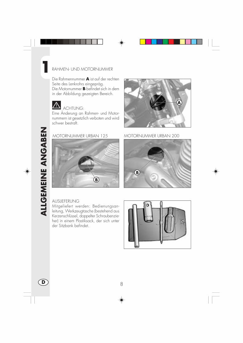
1
ALL
GEM
EIN
E A
NG
ABEN
8D
RAHMEN- UND MOTORNUMMER
Die Rahmennummer A ist auf der rechtenSeite des Lenkrohrs eingepräg.Die Motornummer B befindet sich in demin der Abbildung gezeigten Bereich.
ACHTUNG:Eine Änderung an Rahmen- und Motor-nummern ist gesetzlich verboten und wirdschwer bestraft.
MOTORNUMMER URBAN 200
AUSLIEFERUNGMitgeliefert werden: Bedienungsan-leitung, Werkzeugtasche (bestehend ausKerzenschlüssel, doppelter Schraubenzie-her) in einem Plastiksack, der sich unterder Sitzbank befindet.
MOTORNUMMER URBAN 125
B
B
A
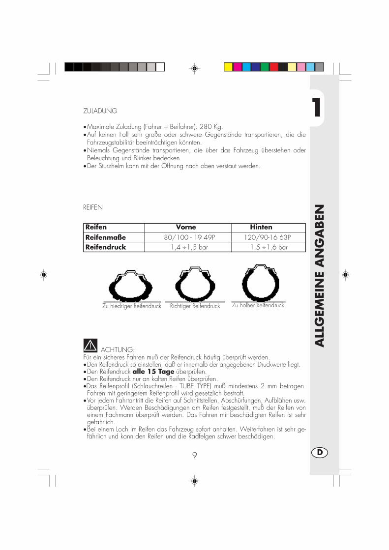
1
ALL
GEM
EIN
E A
NG
ABEN
9 D
ZULADUNG
•Maximale Zuladung (Fahrer + Beifahrer): 280 Kg.•Auf keinen Fall sehr große oder schwere Gegenstände transportieren, die dieFahrzeugstabilität beeinträchtigen könnten.
•Niemals Gegenstände transportieren, die über das Fahrzeug überstehen oderBeleuchtung und Blinker bedecken.
•Der Sturzhelm kann mit der Öffnung nach oben verstaut werden.
ACHTUNG:Für ein sicheres Fahren muß der Reifendruck häufig überprüft werden.•Den Reifendruck so einstellen, daß er innerhalb der angegebenen Druckwerte liegt.•Den Reifendruck alle 15 Tage überprüfen.•Den Reifendruck nur an kalten Reifen überprüfen.•Das Reifenprofil (Schlauchreifen - TUBE TYPE) muß mindestens 2 mm betragen.Fahren mit geringerem Reifenprofil wird gesetzlich bestraft.
•Vor jedem Fahrtantritt die Reifen auf Schnittstellen, Abschürfungen, Aufblähen usw.überprüfen. Werden Beschädigungen am Reifen festgestellt, muß der Reifen voneinem Fachmann überprüft werden. Das Fahren mit beschädigten Reifen ist sehrgefährlich.
•Bei einem Loch im Reifen das Fahrzeug sofort anhalten. Weiterfahren ist sehr ge-fährlich und kann den Reifen und die Radfelgen schwer beschädigen.
REIFEN
Reifen Vorne Hinten Reifenmaße 80/100 - 19 49P 120/90-16 63P Reifendruck 1,4 ÷1,5 bar 1,5 ÷1,6 bar
Zu niedriger Reifendruck Zu holher ReifendruckRichtiger Reifendruck
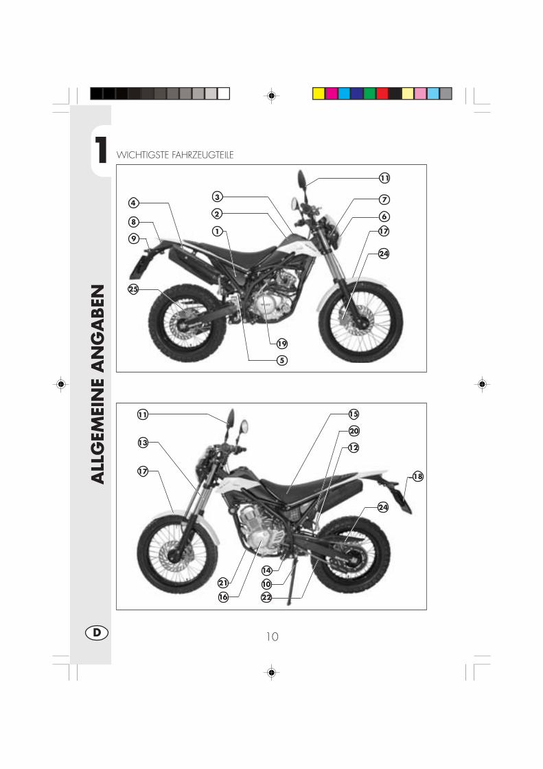
1
ALL
GEM
EIN
E A
NG
ABEN
10D
WICHTIGSTE FAHRZEUGTEILE
1
2
34
5
7
8
9
19
20
13
14
10
15
16
12
17
11
11
18
21
22
24
25
24
17
6
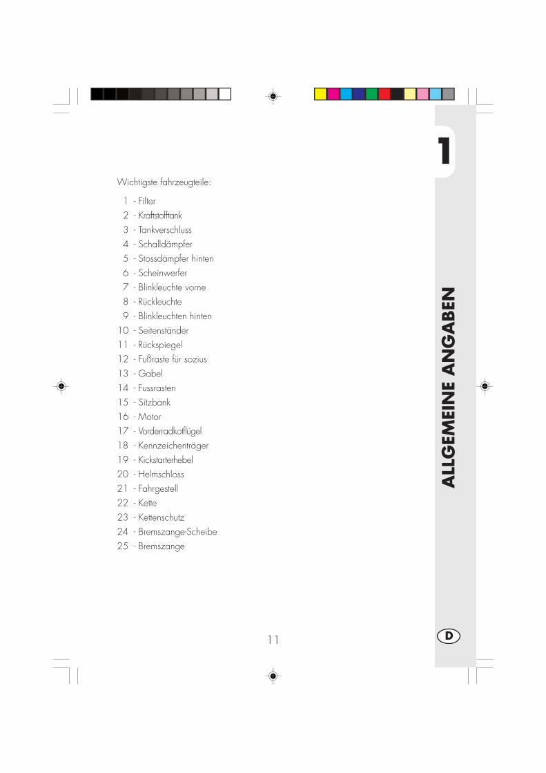
1
ALL
GEM
EIN
E A
NG
ABEN
11 D
Wichtigste fahrzeugteile:
1 - Filter2 - Kraftstofftank3 - Tankverschluss4 - Schalldämpfer5 - Stossdämpfer hinten6 - Scheinwerfer7 - Blinkleuchte vorne8 - Rückleuchte9 - Blinkleuchten hinten
10 - Seitenständer11 - Rückspiegel12 - Fußraste für sozius13 - Gabel14 - Fussrasten15 - Sitzbank16 - Motor17 - Vorderradkotflügel18 - Kennzeichenträger19 - Kickstarterhebel20 - Helmschloss21 - Fahrgestell22 - Kette23 - Kettenschutz24 - Bremszange-Scheibe25 - Bremszange
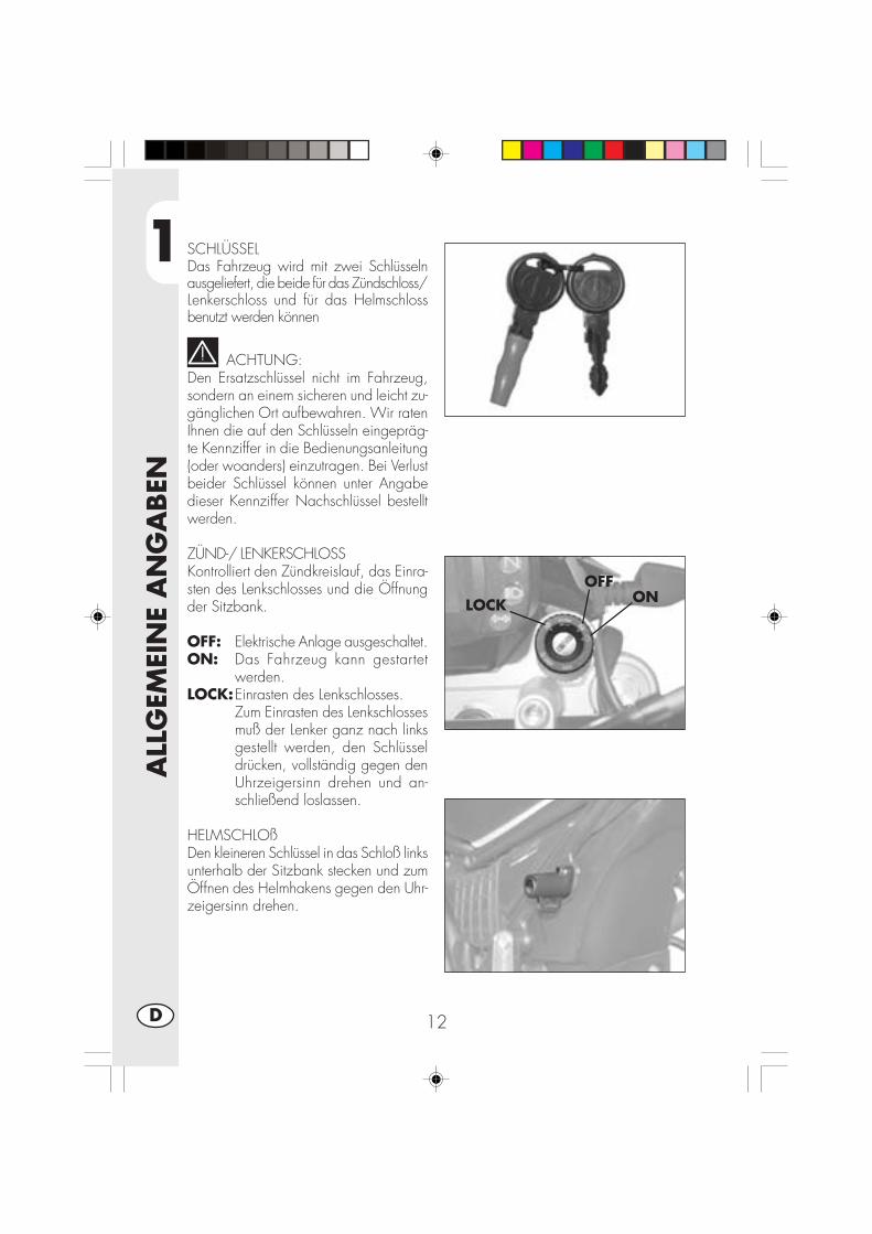
1
ALL
GEM
EIN
E A
NG
ABEN
12D
SCHLÜSSELDas Fahrzeug wird mit zwei Schlüsselnausgeliefert, die beide für das Zündschloss/Lenkerschloss und für das Helmschlossbenutzt werden können
ACHTUNG:Den Ersatzschlüssel nicht im Fahrzeug,sondern an einem sicheren und leicht zu-gänglichen Ort aufbewahren. Wir ratenIhnen die auf den Schlüsseln eingepräg-te Kennziffer in die Bedienungsanleitung(oder woanders) einzutragen. Bei Verlustbeider Schlüssel können unter Angabedieser Kennziffer Nachschlüssel bestelltwerden.
ZÜND-/ LENKERSCHLOSSKontrolliert den Zündkreislauf, das Einra-sten des Lenkschlosses und die Öffnungder Sitzbank.
OFF: Elektrische Anlage ausgeschaltet.ON: Das Fahrzeug kann gestartet
werden.LOCK:Einrasten des Lenkschlosses.
Zum Einrasten des Lenkschlossesmuß der Lenker ganz nach linksgestellt werden, den Schlüsseldrücken, vollständig gegen denUhrzeigersinn drehen und an-schließend loslassen.
HELMSCHLOßDen kleineren Schlüssel in das Schloß linksunterhalb der Sitzbank stecken und zumÖffnen des Helmhakens gegen den Uhr-zeigersinn drehen.
ONOFF
LOCK

1
ALL
GEM
EIN
E A
NG
ABEN
13 D
ARMATURENBRETT UND BEDIENUNGSELEMENTE
Anmerkung: Das Aufleuchten der Kontrollampe Seitenständer zeigt an, dass derSeitenständer ausgeklappt ist. Aus Sicherheitsgründen stellt sich dann bei Einlegeneines Gangs das Motorrad ab.
2
10
11
8
1
9
6
3
5
4
7
12
13
14
15
16
17
1- LCD2- Zündschloss3- Leerlaufpunkt-Kontrolllampe4- Blinker-Kontrolllampe5- Fernlichtkontrolle6- Kippständer-Kontrolllampe7- Taste SCROLL8- Kupplungshebel9- Choke-Hebel (nur an Urban125)
10 - Bremshebel Vorderradbremse11 - Gasgriff12 - Anlasserschalter13 - Schalter zum Ausschalten des Motors14 - Blinkerschalter15 - Hupenschalter16 - Licht-Wechselschalter17 - Lichthupe

1
ALL
GEM
EIN
E A
NG
ABEN
14D
ANLEITUNG ZUM EINSTELLEN UND BETRIEB DES KILOMETERZÄHLERS
INHALTSVERZEICHNIS
ABSATZ I NHALT
10.0 Start-Text und Startseite10.1 Kontrolllampen10.2 Ist-Geschwindigkeit und Gesamt-Kilometerstand (ODO)
20.0 Sonderfunktionen20.1 Teilstrecken-Kilometerzähler (TRP)20.2 Uhr (CLK)20.3 Chronometer (LAP)20.4 Erreichte Höchstgeschwindigkeit (MAX)
30.0 Längeres Stilllegen
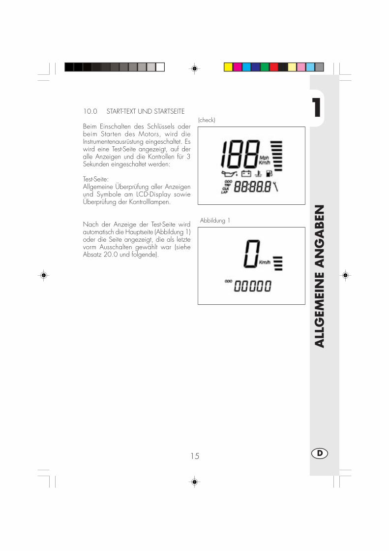
1
ALL
GEM
EIN
E A
NG
ABEN
15 D
10.0 START-TEXT UND STARTSEITE
Beim Einschalten des Schlüssels oderbeim Starten des Motors, wird dieInstrumentenausrüstung eingeschaltet. Eswird eine Test-Seite angezeigt, auf deralle Anzeigen und die Kontrollen für 3Sekunden eingeschaltet werden:
Test-Seite:Allgemeine Überprüfung aller Anzeigenund Symbole am LCD-Display sowieÜberprüfung der Kontrolllampen.
Nach der Anzeige der Test-Seite wirdautomatisch die Hauptseite (Abbildung 1)oder die Seite angezeigt, die als letztevorm Ausschalten gewählt war (sieheAbsatz 20.0 und folgende).
(check)
Abbildung 1
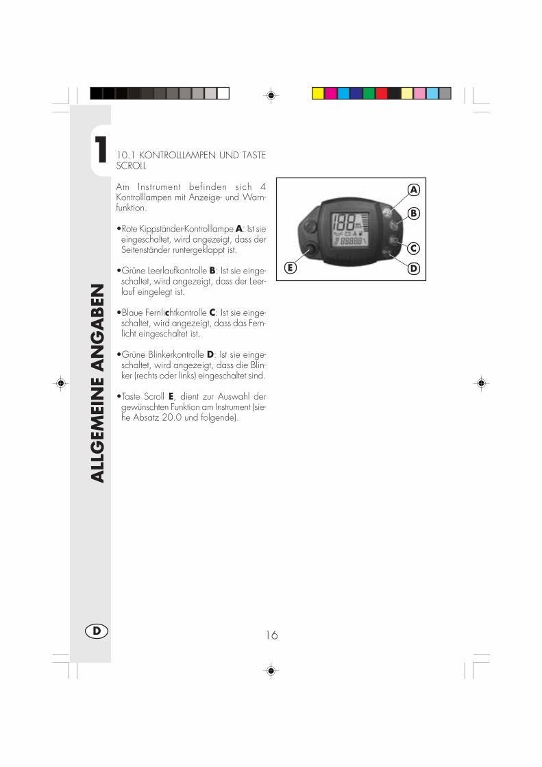
1
ALL
GEM
EIN
E A
NG
ABEN
16D
10.1 KONTROLLLAMPEN UND TASTESCROLL
Am Instrument befinden sich 4Kontrolllampen mit Anzeige- und Warn-funktion.
•Rote Kippständer-Kontrolllampe A: Ist sieeingeschaltet, wird angezeigt, dass derSeitenständer runtergeklappt ist.
•Grüne Leerlaufkontrolle B: Ist sie einge-schaltet, wird angezeigt, dass der Leer-lauf eingelegt ist.
•Blaue Fernlichtkontrolle C: Ist sie einge-schaltet, wird angezeigt, dass das Fern-licht eingeschaltet ist.
•Grüne Blinkerkontrolle D: Ist sie einge-schaltet, wird angezeigt, dass die Blin-ker (rechts oder links) eingeschaltet sind.
•Taste Scroll E, dient zur Auswahl dergewünschten Funktion am Instrument (sie-he Absatz 20.0 und folgende).
A
B
C
DE
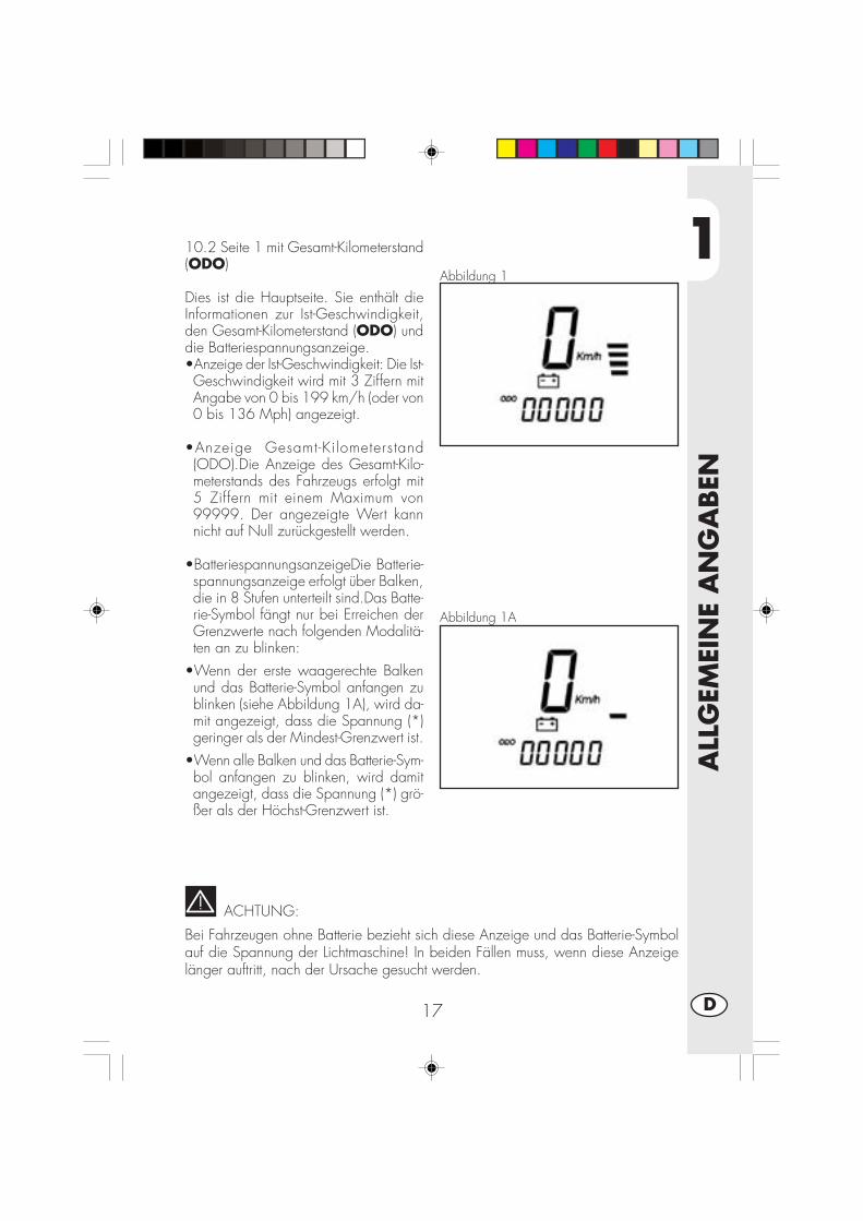
1
ALL
GEM
EIN
E A
NG
ABEN
17 D
Abbildung 1
Abbildung 1A
10.2 Seite 1 mit Gesamt-Kilometerstand(ODO)
Dies ist die Hauptseite. Sie enthält dieInformationen zur Ist-Geschwindigkeit,den Gesamt-Kilometerstand (ODO) unddie Batteriespannungsanzeige.•Anzeige der Ist-Geschwindigkeit: Die Ist-Geschwindigkeit wird mit 3 Ziffern mitAngabe von 0 bis 199 km/h (oder von0 bis 136 Mph) angezeigt.
•Anzeige Gesamt-Kilometerstand(ODO).Die Anzeige des Gesamt-Kilo-meterstands des Fahrzeugs erfolgt mit5 Ziffern mit einem Maximum von99999. Der angezeigte Wert kannnicht auf Null zurückgestellt werden.
•BatteriespannungsanzeigeDie Batterie-spannungsanzeige erfolgt über Balken,die in 8 Stufen unterteilt sind.Das Batte-rie-Symbol fängt nur bei Erreichen derGrenzwerte nach folgenden Modalitä-ten an zu blinken:
•Wenn der erste waagerechte Balkenund das Batterie-Symbol anfangen zublinken (siehe Abbildung 1A), wird da-mit angezeigt, dass die Spannung (*)geringer als der Mindest-Grenzwert ist.
•Wenn alle Balken und das Batterie-Sym-bol anfangen zu blinken, wird damitangezeigt, dass die Spannung (*) grö-ßer als der Höchst-Grenzwert ist.
ACHTUNG:
Bei Fahrzeugen ohne Batterie bezieht sich diese Anzeige und das Batterie-Symbolauf die Spannung der Lichtmaschine! In beiden Fällen muss, wenn diese Anzeigelänger auftritt, nach der Ursache gesucht werden.
1
ALL
GEM
EIN
E A
NG
ABEN
18D
20.0 SONDERFUNKTIONENVon der Hauptseite kann man nacheinander die folgenden Sonderfunktionen errei-chen, auf denen Informationen entsprechend der folgenden Liste angezeigt werden:
Teilstrecken-Kilometerstand (TRP)Uhr (CLK)Chronometer (LAP)Höchstgeschwindigkeit (MAX)
Außer den Informationen zur spezifischen Seite werden am Display weiterhin die Ist-Geschwindigkeit und die Batteriespannung/ Batterie-Symbol angezeigt.
Die einzelnen Seite sind ab der Hauptseite (ODO) durch kurzen Druck auf die TasteSCROLL in Reihenfolge abrufbar. Die einzelnen Seiten werden in folgender Reihen-folge angezeigt:
ODO -> TRP -> CLK -> LAP -> MAX
Wird die Taste SCROLL erneut gedrückt, wenn die Seite mit der Höchstgeschwin-digkeit (MAX) angezeigt wird, wird erneut auf die Hauptseite (ODO) zurückgestelltund die anderen Seite können nach Belieben wieder aufgerufen werden.
ACHTUNG:DIE BETÄTIGUNG DER TASTE SCROLL IST WÄHREND DER FAHRT NICHT GE-STATTET, D. H., WENN FÜR DIE IST-GESCHWINDIGKEIT EIN ANDERER WERTALS 0 Km/h-Mph ANGEZEIGT WIRD.DAMIT SOLL DIE SICHERHEIT BEIM LENKEN DES FAHRZEUGS GARANTIERTWERDEN.
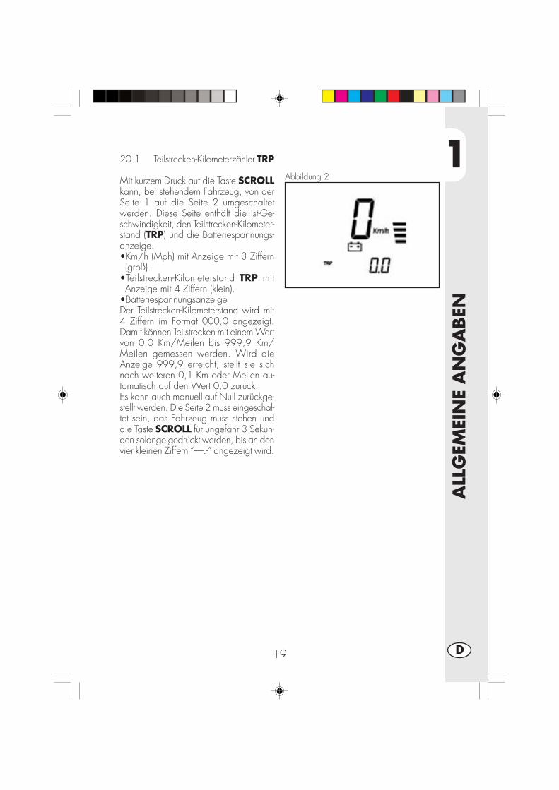
1
ALL
GEM
EIN
E A
NG
ABEN
19 D
Abbildung 2
20.1 Teilstrecken-Kilometerzähler TRP
Mit kurzem Druck auf die Taste SCROLLkann, bei stehendem Fahrzeug, von derSeite 1 auf die Seite 2 umgeschaltetwerden. Diese Seite enthält die Ist-Ge-schwindigkeit, den Teilstrecken-Kilometer-stand (TRP) und die Batteriespannungs-anzeige.•Km/h (Mph) mit Anzeige mit 3 Ziffern(groß).
•Teilstrecken-Kilometerstand TRP mitAnzeige mit 4 Ziffern (klein).
•BatteriespannungsanzeigeDer Teilstrecken-Kilometerstand wird mit4 Ziffern im Format 000,0 angezeigt.Damit können Teilstrecken mit einem Wertvon 0,0 Km/Meilen bis 999,9 Km/Meilen gemessen werden. Wird dieAnzeige 999,9 erreicht, stellt sie sichnach weiteren 0,1 Km oder Meilen au-tomatisch auf den Wert 0,0 zurück.Es kann auch manuell auf Null zurückge-stellt werden. Die Seite 2 muss eingeschal-tet sein, das Fahrzeug muss stehen unddie Taste SCROLL für ungefähr 3 Sekun-den solange gedrückt werden, bis an denvier kleinen Ziffern “—.-“ angezeigt wird.
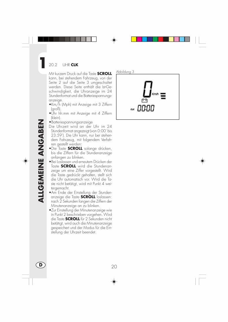
1
ALL
GEM
EIN
E A
NG
ABEN
20D
Abbildung 3
20.2 UHR CLK
Mit kurzem Druck auf die Taste SCROLLkann, bei stehendem Fahrzeug, von derSeite 2 auf die Seite 3 umgeschaltetwerden. Diese Seite enthält die Ist-Ge-schwindigkeit, die Uhranzeige im 24Stundenformat und die Batteriespannungs-anzeige.•Km/h (Mph) mit Anzeige mit 3 Ziffern(groß).
•Uhr hh:mm mit Anzeige mit 4 Ziffern(klein).
•BatteriespannungsanzeigeDie Uhrzeit wird an der Uhr im 24Stundenformat angezeigt (von 0:00’ bis23:59’). Die Uhr kann, nur bei stehen-dem Fahrzeug, mit folgendem Verfah-ren gestellt werden:
•Die Taste SCROLL solange drücken,bis die Ziffern für die Stundenanzeigeanfangen zu blinken.
•Bei Loslassen und erneutem Drücken derTaste SCROLL wird die Stundenan-zeige um eine Ziffer vorgestellt. Wirddie Taste gedrückt gehalten, stellt sichdie Uhr automatisch vor. Wird die Ta-ste nicht betätigt, wird mit Punkt 4 wei-tergemacht.
•Am Ende der Einstellung der Stunden-anzeige die Taste SCROLL loslassen:nach 2 Sekunden fangen die Ziffern derMinutenanzeige an zu blinken.
•Zur Einstellung der Minutenanzeige wiein Punkt 2 beschrieben vorgehen. Wirddie Taste SCROLL für 2 Sekunden nichtbetätigt, wird auch die Minutenanzeigegespeichert und der Modus für die Ein-stellung der Uhrzeit beendet.

1
ALL
GEM
EIN
E A
NG
ABEN
21 D
Abbildung 4
20.3 CHRONOMETER LAP
Mit kurzem Druck auf die Taste kann, beistehendem Fahrzeug, von der Seite 3 aufdie Seite 4 umgeschaltet werden. DieseSeite enthält die Ist-Geschwindigkeit, dasChronometer Minuten:Sekunden und dieBatteriespannungsanzeige.•Km/h (Mph) mit Anzeige mit 3 Ziffern(groß).
•Chronometer mm:ss mit Anzeige mit 4Ziffern (klein).
•Batteriespannungsanzeige.Wird die Seite wie in der Abbildung “Sei-te 4” angezeigt, kann die Chronometer-Funktion, nachdem sie eingeschaltet wur-de, genutzt werden. Zum Einschaltenmuss die Taste SCROLL länger als 1Sekunden gedrückt werden, bis die An-zeige “—:—“ verschwindet und dasChronometer im FormatMINUTEN:SEKUNDEN angezeigt wird(siehe Abbildung 4A).
Abbildung 4A

1
ALL
GEM
EIN
E A
NG
ABEN
22D
Funktion: Das manuelle und automatische Starten und Anhalten des Chronome-ters kann nur erfolgen, wenn das Instrument auf “Abbildung 4A” eingestellt ist.•Das manuelle Starten und Anhalten erfolgt durch kurzen Druck auf die Taste. Dasgilt sowohl für das Starten als auch für das Anhalten (nur bei stehendem Fahrzeugeingeschaltet).
•Das automatische Starten erfolgt beim Losfahren des Fahrzeugs und das automati-sche Anhalten erfolgt ungefähr 1 Sekunde nach dem Anhalten des Fahrzeugs (mitautomatischer Berichtigung des angezeigten Wertes).
Ein Anhalten der Zählung erfolgt auch, wenn ein bereits fahrendes Fahrzeug ange-halten wird (auch wenn manuell gestartet wurde). Voraussetzung ist, dass die SeiteLAP eingeschaltet ist.
Abbildung 4AIn dieser Abbildung wird das Chronome-ter mit der abgelaufenen Zeit angezeigt:bei angehaltener und auf Null zurückge-stellter Zählung werden alle Ziffern mitNull angezeigt (siehe Abbildung 4A).Wenn die Anzeige “LAP” blinkt, wirddamit angezeigt, dass das Chronometereingeschaltet ist. Diese Anzeige findetsich in dem Fall auch auf allen anderenSeiten.Es können bei eingeschaltetem Chrono-meter auch andere als die Chronometer-Seite aufgerufen werden. Wie folgt vor-gehen.Nullstellen des Chronometers:Bei Anzeige der Abbildung 4A die TasteSCROLL länger als 2 Sekunden drük-ken. Zuerst wird Abbildung 4 und dannwieder Abbildung 4A mit der vom Chro-nometer erfassten Zeit angezeigt. BeimLoslassen der Taste SCROLL wird dasChronometer auf Null zurückgestellt undangehalten.Beenden (Ausschalten) der Ab-bildung LAP: Bei Anzeige der Seite 4A die Taste zwi-schen 1 und 2 Sekunden drücken, bisSeite 4 wieder angezeigt wird, anschlie-ßend die Taste loslassen. Durch erneutenkurzen Druck auf die Taste wird auf dienächste Seite umgeschaltet. Das Chrono-meter bleibt eingeschaltet und die Anzei-ge LAP blinkt.

1
ALL
GEM
EIN
E A
NG
ABEN
23 D
Figura 5
20.4 ERREICHTE HÖCHSTGE-SCHWINDIGKEIT MAXMit kurzem Druck auf die Taste SCROLLkann, bei stehendem Fahrzeug, von derSeite 4 auf die Seite 5 umgeschaltetwerden. Diese Seite enthält die Ist-Ge-schwindigkeit, die erreichte Höchstge-schwindigkeit und die Batteriespannungs-anzeige.•Km/h (Mph) mit Anzeige mit 3 Ziffern(groß).
•Erreichte Höchstgeschwindigkeit mitAnzeige mit 3 Ziffern (klein).
•Batteriespannungsanzeige.Auf dieser Seite blinkt die Anzeige “Km/h” oder “Mph”.Während der Fahrt wird die erreichteHöchstgeschwindigkeit ständig aktuali-siert und an den drei kleinen Ziffern an-gezeigt. Dieser Wert wird auf alle Fällegespeichert, auch wenn die Seite 5 nichtgeöffnet ist.Es kann auf Null zurückgestellt werden.Die Seite 5 muss eingeschaltet sein, dasFahrzeug muss stehen und die TasteSCROLL für ungefähr 3 Sekunden so-lange gedrückt werden, bis an den 3 klei-nen Ziffern “—“ angezeigt wird.Um auf die Hauptseite 1 zurückzustellen,die Taste SCROLL kurz betätigen.
30.0 Längeres StilllegenDas Digitalinstrument wird über dieFahrzeugbatterie mit Strom versorgt. Beieinem längeren Stilllegen sollte die Bat-terie getrennt werden.Beim Trennen der Batterie geht dieUhrzeiteinstellung und die Information zurerreichten Höchstgeschwindigkeit verlo-ren.

1
ALL
GEM
EIN
E A
NG
ABEN
24D
TECHNISCHE DATEN
MAXIMALE ZULADUNG
Fahrer + Beifahrer .......................................................................... 280 kg
FAHRZEUGGEWICHT
Fahrbereit (leer) ALP 200 ................................................................. 103 kg
Fahrbereit (leer) ALP 125 ................................................................. 101 kg
FAHRZEUGMAßE
Gesamtlänge ............................................................................ 2143 mm
Gesamtbreite .............................................................................. 820 mm
Gesamthöhe ............................................................................. 1170 mm
Radstand .................................................................................. 1372 mm
Zitzhöhe ..................................................................................... 836 mm
Bodenfreiheit ............................................................................... 288 mm
RAHMEN .. Doppelschleifen Rohrrahnen aus Stahl mit Geschloßenen Unterzuegen
FASSUNGSVERMÖGEN
Tank inhalt ........................................................................................ 6 (lt)
Reserve ......................................................................................... 1,5 (lt)
Durchschnittsverbrauch ............................................................... 25 km/ (lt)

1
ALL
GEM
EIN
E A
NG
ABEN
25 D
RADAUFHÄNGUNG VORNE
Hydraulische Teleskopgabel Schaftdurchmesser Ø 38 mm.
Öl-Menge pro Schaft
- rechts ................................................................................... 310 ± 5 cc
- links ..................................................................................... 310 ± 5 cc
Öltyp .................................................................................. SHELL EBH16
Ölstand ......................................... 142 mm unterhalb des oberen Rohrrandes
bei Gabel an Hubende und ohne Feder
Vorlauf ...................................................................................... 82,5 mm
RADAUFHÄNGUNG HINTENProgressiver hydraulischer Einzelstoßdämpfer, einstellbare Federdehnung und Feder-vorspannung.
Stoßdämpferhub ............................................................................ 63 mm
VORDERRADBREMSE
Hydraulische Scheibenbremse mit Scheibe Ø 245 mm
HINTERRADBREMSE
Hydraulische Scheibenbremse mit Scheibe Ø 220 mm

1
ALL
GEM
EIN
E A
NG
ABEN
26D
Motor URBAN 125
Typ: ........................................ Einzylinder, nach vorne geneigt, 4-Takt, SOHC
Bohrung x Hub (mm) .................................................................. 54X54 mm
Hubraum (cm3) ............................................................................ 124 cm3
Verdichtung .................................................................................... 10 : 1
Vergaser .........................................................MIKUNI UCAL 5Nh Ø26-38
Schmierung ............................................................ Mit Öl aus der Ölwanne
Gemischversorgung ........Mit Benzin (bleifrei Mindestoktanzahl 95) über Vergaser
Kühlung ................................................................................... Luftgekuehlt
Gabel ............................................................................ NGK R CR7 HSA
Kupplung .................................................... Mehrscheibenkupplung in Ölbad
Getriebe ........................................................................ 5-Gang-Getriebe
Haupt-Übersetzungsverhältnis ............................................................. 68-20
Übersetzungsverhältnis Endantrieb ..................................................... 60/14
Übersetzungsverhältnis 1. Gang ....................................................... 37/14
Übersetzungsverhältnis 2. Gang ....................................................... 32/18
Übersetzungsverhältnis 3. Gang ....................................................... 25/19
Übersetzungsverhältnis 4. Gang ....................................................... 23/22
Übersetzungsverhältnis 5. Gang ....................................................... 21/24
Antriebskette..................................................... REGINA 1/2, 5/16 P. 136
Ventilspiel .............................................. Einlaß mm 0,08, Auslaßventil 0,13
Starter ............................................................................... Elektro und Kick
Motoröl ................................................................. BARDAHL XTM15W 50
Fassungsvermögen Motoröl ............................................ 1,000 ml/1,050 ml
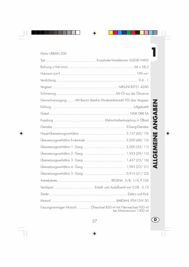
1
ALL
GEM
EIN
E A
NG
ABEN
27 D
Motor URBAN 200
Typ: .................................................. Einzylinder-Viertaktmotor SUZUKI H402
Bohrung x Hub (mm) ...................................................................66 x 58,2
Hubraum (cm3) ............................................................................ 199 cm3
Verdichtung ................................................................................... 9,4 : 1
Vergaser ................................................................... MIKUNI BST31 42AD
Schmierung ............................................................ Mit Öl aus der Ölwanne
Gemischversorgung ........Mit Benzin (bleifrei Mindestoktanzahl 95) über Vergaser
Kühlung ................................................................................... Luftgekuehlt
Gabel ................................................................................. NGK DR8 EA
Kupplung .................................................... Mehrscheibenkupplung in Ölbad
Getriebe ........................................................................ 5-Gang-Getriebe
Haupt-Übersetzungsverhältnis ............................................... 3,157 (60/ 19)
Übersetzungsverhältnis Endantrieb ........................................ 3,200 (48/ 15)
Übersetzungsverhältnis 1. Gang .......................................... 3,000 (33/ 11)
Übersetzungsverhältnis 2. Gang .......................................... 1,933 (29/ 15)
Übersetzungsverhältnis 3. Gang .......................................... 1,437 (23/ 16)
Übersetzungsverhältnis 4. Gang .......................................... 1,095 (23/ 21)
Übersetzungsverhältnis 5. Gang .......................................... 0,913 (21/ 23)
Antriebskette...................................................... REGINA 5/8, 1/4, P.104
Ventilspiel ........................................ Einlaß- und Auslaßventil mm 0,08 - 0,13
Starter ............................................................................... Elektro und Kick
Motoröl ................................................................. BARDAHL XTM15W 50
Fassungsvermögen Motoröl ............. Ölwechsel 850 ml mit Filterwechsel 950 mlbei Motorrevision 1300 ml

1
ALL
GEM
EIN
E A
NG
ABEN
28D
SCHEMA ELETTRICO URBAN 125

1
ALL
GEM
EIN
E A
NG
ABEN
29 D
ELEKTRISCHER SCHALTPLAN URBAN1251) R. BLINKER (LAMPE12V-10W)2) STOPSCHALTER3) RECHTER LENKERSCHALTER4) ANSCHLAG5) STARTERKNOPF6) SPIONSEITENSTANDPLATZ7) LEERLAUFANZEIGEKONTROLLAMPE8) FERNLICHTKONTROLLAMPE9) BÜNKLICHTKONTROLLAMPE10) DISPLAY11) SENSOR12) VORDERER SCHEINWERFER (12V-5560W)13) LAMPADA12V-5W14) HUPENDRUCKKNOPF15) DRUCKKNOPF FLASH16) UMSCHALTER FERNLICHT/FAHRLICHT17) BLINKLICHTSCHALTER18) LINKER LENKERSCHALTER19) HUPENDRUCKKNOPF20) ZÜNDSPULE21) BLINKGEBER22) L. BLINKER (LAMPE 12V-10W)23) REGLER 12V24) KONDENSATOR25) STARTERMOTOR26) MASSE27) DIODENEINHEIT 1A28) SICHERUNG 15A29) STARTERRELAIS30) HERMETISCHE BATTERIE 12V-9Ah31) BLINKER L (LAMPE 12V-10W)32) GLÜHBIRNE NUMMERNSCHILDBELEUCHTUNG (LAMPE 12V-5W)33) MASSE34) POSIT.LEUCHTE35) STOP36) DIODE 1A37) RÜCKLEUCHTE (LED)38) BLINKER R (LAMPADA 12V-10W)39) BREMSLICHTSCHALTER40) SENSOR41) SENSOR P.T.C.42) SENSOR43) MASSE44) KONTAKT, LEERLAUFSCHALTER45) DIODE 1A46) PICK-UP47) ELEKTRONISCHES STEUERGERÄT48) ZÜNDSCHALTER49) HUPEFarberklärungBi = WeißVe = GrünMa= BraunVi = Violett
Bl = BlauNe = SchwarzGi = GelbRs = Rot
Ar = OrangeAz = HellblauRo = RosaGr = Grau
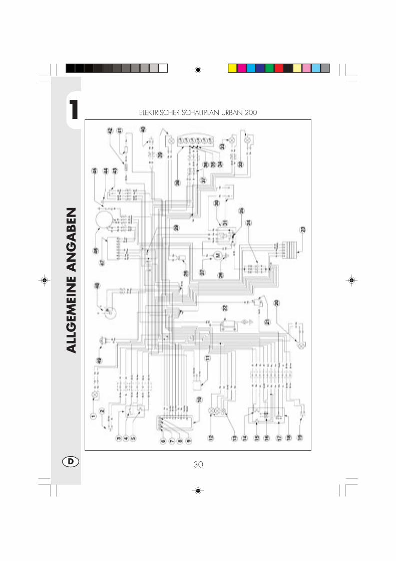
1
ALL
GEM
EIN
E A
NG
ABEN
30D
ELEKTRISCHER SCHALTPLAN URBAN 200
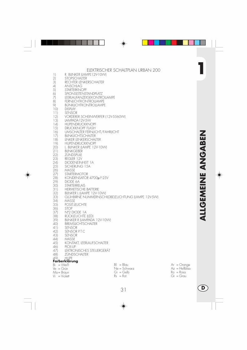
1
ALL
GEM
EIN
E A
NG
ABEN
31 D
FarberklärungBi = WeißVe = GrünMa= BraunVi = Violett
Bl = BlauNe = SchwarzGi = GelbRs = Rot
Ar = OrangeAz = HellblauRo = RosaGr = Grau
ELEKTRISCHER SCHALTPLAN URBAN 2001) R. BLINKER (LAMPE12V-10W)2) STOPSCHALTER3) RECHTER LENKERSCHALTER4) ANSCHLAG5) STARTERKNOPF6) SPIONSEITENSTANDPLATZ7) LEERLAUFANZEIGEKONTROLLAMPE8) FERNLICHTKONTROLLAMPE9) BÜNKLICHTKONTROLLAMPE10) DISPLAY11) SENSOR12) VORDERER SCHEINWERFER (12V-5560W)13) LAMPADA12V-5W14) HUPENDRUCKKNOPF15) DRUCKKNOPF FLASH16) UMSCHALTER FERNLICHT/FAHRLICHT17) BLINKLICHTSCHALTER18) LINKER LENKERSCHALTER19) HUPENDRUCKKNOPF20) L. BLINKER (LAMPE 12V-10W)21) BLINKGEBER22) ZÜNDSPULE23) REGLER 12V24) DIODENEINHEIT 1A25) SICHERUNG 15A26) MASSE27) STARTERMOTOR28) KONDENSATOR 4700μ F-25V29) DIODE 6A30) STARTERRELAIS31) HERMETISCHE BATTERIE32) BLINKER L (LAMPE 12V-10W)33) GLÜHBIRNE NUMMERNSCHILDBELEUCHTUNG (LAMPE 12V-5W)34) MASSE35) POSIT.LEUCHTE36) STOP37) Nº2 DIODE 1A38) RÜCKLEUCHTE (LED)39) BLINKER R (LAMPADA 12V-10W)40) BREMSLICHTSCHALTER41) SENSOR42) SENSOR P.T.C43) SENSOR44) MASSE45) KONTAKT, LEERLAUFSCHALTER46) PICK-UP47) LEKTRONISCHES STEUERGERÄT48) ZÜNDSCHALTER49) HUPE
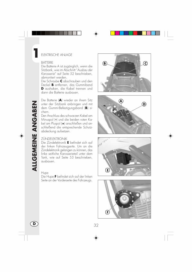
1
ALL
GEM
EIN
E A
NG
ABEN
32D
ELEKTRISCHE ANLAGE
BATTERIEDie Batterie A ist zugänglich, wenn dieSitzbank, wie im Abschnitt “Ausbau derKarosserie” auf Seite 52 beschrieben,abmontiert werden.Die Schraube C abschrauben und denDeckel B entfernen, das GummibandD aushaken, die Kabel trennen unddann die Batterie ausbauen.
Die Batterie (A) wieder an ihrem Sitzunter der Sitzbank anbringen und mitdem Gummi-Befestigungsband (B) si-chern.Den Anschluss des schwarzen Kabel amMinuspol (-) und die beiden roten Ka-bel am Pluspol (+) anschließen und an-schließend die entsprechende Schutz-abdeckung aufsetzen.
ZÜNDELEKTRONIKDie Zündelektronik E befindet sich aufder linken Fahrzeugseite. Um an dieZündelektronik gelangen zu können, daslinke seitliche Karosserieteil unter demTank, wie auf Seite 53 beschrieben,ausbauen.
HupeDie Hupe F befindet sich auf der linkenSeite an der Vorderseite des Fahrzeugs.
AD
F
B C
E

1
ALL
GEM
EIN
E A
NG
ABEN
33 D
LINKGEBERDer Blinkgeber G befindet sich unterhalbdes Tanks. Um an den Blinkgebergelangen zu können, das rechte seitlicheKarosserieteil unter dem Tank, wie aufSeite 53 beschrieben, ausbauen.
ZÜNDSPULE - ANLASSERRELAIS -STÄNDERRELAIS - SICHERUNGIn der Mitte auf der linken Fahrzeugseitebefinden sich: Die Spule H desAnlasserrelais I, das Ständerrelais L unddie Sicherung M.Mit der Sicherung sind folgendeAbnehmer gesichert:- Hupe- Blinker- Instrumentenausrüstung- Zündung Motor
Anmerkungen:Eine durchgebrannte Sicherung darf nurdurch eine andere gleichwer tigeSicherung ersetzt werden. Sollte die neueSicherung nach dem Einbau ebenfallsdurchbrennen, sollten Sie sich unbedingtan eine autorisier te BETAMOTORFachwerkstatt wenden.Die Sicherung hat eine Leistung von 15Ampere.
ACHTUNG:Auf keinen Fall eine Sicherung mitgrößerer Leistung einbauen oderversuchen die Sicherung zu “reparieren”.Falsche Arbeiten können zu einem Ausfallder gesamten elektrischen Anlage führen.
SPANNUNGSREGLERIn der Mitte ist der Spannungsregler Nangebracht.
H
L
N
I
M
G
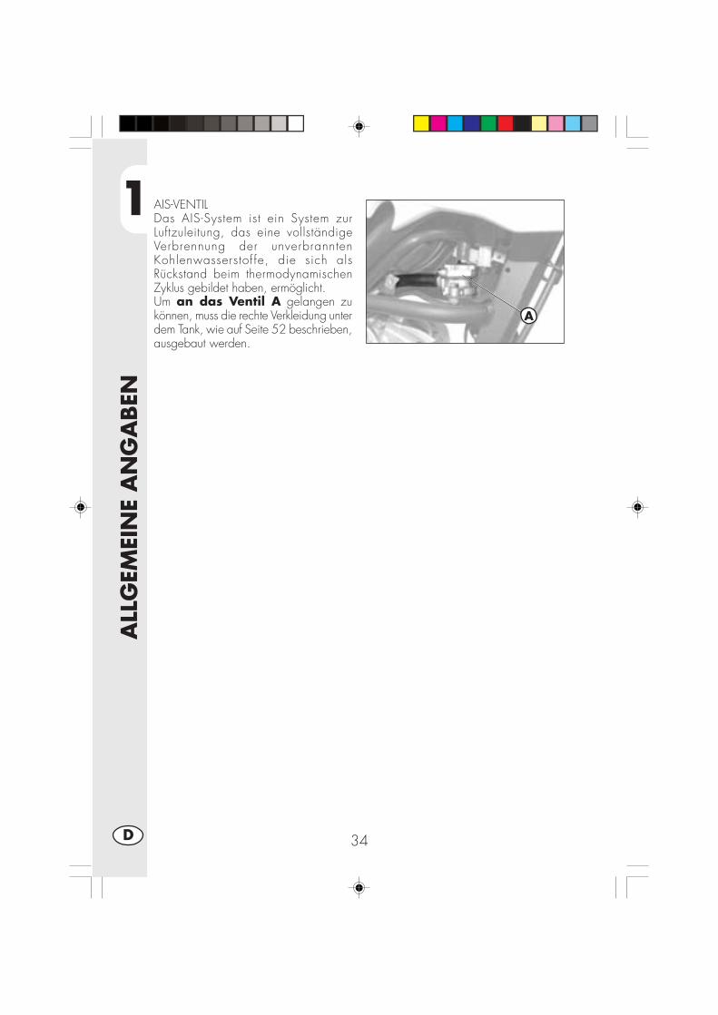
1
ALL
GEM
EIN
E A
NG
ABEN
34D
AIS-VENTILDas AIS-System ist ein System zurLuftzuleitung, das eine vollständigeVerbrennung der unverbranntenKohlenwasserstof fe, die sich alsRückstand beim thermodynamischenZyklus gebildet haben, ermöglicht.Um an das Ventil A gelangen zukönnen, muss die rechte Verkleidung unterdem Tank, wie auf Seite 52 beschrieben,ausgebaut werden.
A

2
BED
IEN
UN
GSV
ORSC
HRIF
TEN
35 D
INHALTSVERZEICHNIS
KAPITEL 2 BEDIENUNGSVORSCHRIFTEN
Kontrollen und Wartung vor und nach Einsatz im Gelände
Empfohlene Schmiermittel und Flüssigkeiten
Einfahren
Starten des Motors
Abstellen des Motors
Tanken
2
BED
IEN
UN
GSV
ORSC
HRIF
TEN
36D
KONTROLLEN UND WARTUNG VOR UND NACH EINSATZ IM GELÄNDE
Um unangenehme Störungen während der Fahrt mit dem Fahrzeug zu vermeiden,sollte das Fahrzeug vor und nach jedem Einsatz kontrolliert und gewartet werden.Die kurze Zeit, die sie für diese Arbeiten aufbringen, wird Ihnen helfen, Geld undZeit zu sparen. Wie folgt vorgehen:
REIFEN Reifendruck und Profiltiefe prüfen (seite.9)RADSPEICHEN Speichen auf richtige Spannung überprüfenSCHRAUBEN UND BOLZEN Alle Schrauben und Bolzen richtig festziehenKETTE Kettenspannung prüfen (Durchhang 20 mm) und ge-
gebenenfalls fettenLUFTFILTER Filter reinigen und mit Öl tränken (seite.48)
Anmerkung:Sicherstellen, dass die Fahrzeugpapier vorhanden sind.An kalten Tagen sollte der Motor vorm Losfahren für kurze Zeit im Leerlauf warmlau-fen. Nach jedem Einsatz im Gelände muß das Fahrzeug gründlich gereinigt wer-den.

2
BED
IEN
UN
GSV
ORSC
HRIF
TEN
37 D
PRODUKTTYP TECHNISCHE DATEN
MOTORÖL BARDAHL XTM 15W 50
BREMSFLÜSSIGKEIT BARDAHL BRAKE FLUID DOT4
GABELÖL SHELL EBH 16
GELENKE, ZUGSTANGEN BARDAHL Outboard Grease NLGI2
EMPFOHLENE SCHMIERMITTEL UND FLÜSSIGKEITEN
Für einen besseren Betrieb und längere Haltbarkeit des Fahrzeugs empfehlen wirIhnen die in der nachstehenden Tabelle aufgeführten Produkte zu verwenden:
Anmerkung:Zum Austausch der Schmiermittel müssen die Angaben in der Tabelle genau einge-halten werden (seite 57)
EINFAHREN
Die Einfahrzeit dauert ungefähr 10 Betriebsstunden, während dieser Zeit müssenfolgenden Vorschriften eingehalten werden:•Den Motor vorm Losfahren warmlaufen lassen;•Fahrten mit gleichbleibender Geschwindigkeit vermeiden. Bei Geschwindigkeits-änderungen spielen sich die mechanischen Bauteile schneller und gleichmäßigerein.
•Den Gasgriff nicht mehr als 3/4 Umdrehung öffnen;
ACHTUNG:•Nach den ersten 1000 Km muß das Getriebeöl gewechselt werden.•Ausschließlich bleifreies Superbenzin tanken.•Nach dem ersten Einsatz im Gelände alle Schrauben und Bolzen überprüfen.
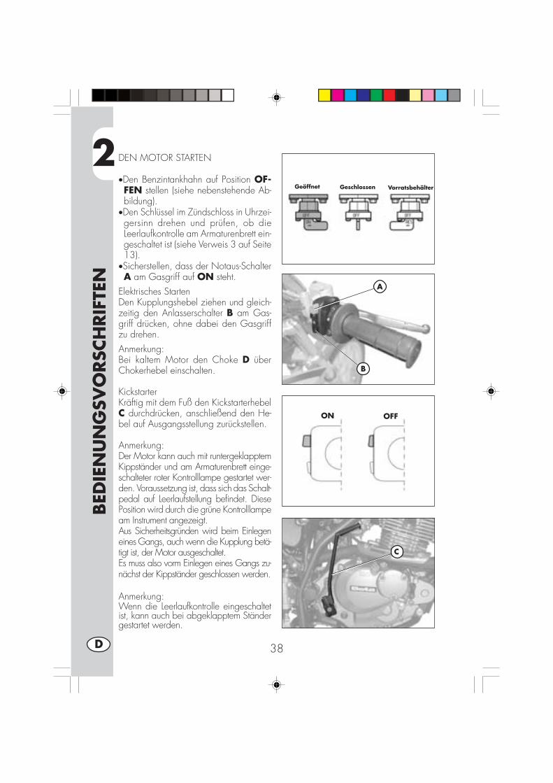
2
BED
IEN
UN
GSV
ORSC
HRIF
TEN
38D
DEN MOTOR STARTEN
•Den Benzintankhahn auf Position OF-FEN stellen (siehe nebenstehende Ab-bildung).
•Den Schlüssel im Zündschloss in Uhrzei-gersinn drehen und prüfen, ob dieLeerlaufkontrolle am Armaturenbrett ein-geschaltet ist (siehe Verweis 3 auf Seite13).
•Sicherstellen, dass der Notaus-SchalterA am Gasgriff auf ON steht.
Elektrisches StartenDen Kupplungshebel ziehen und gleich-zeitig den Anlasserschalter B am Gas-griff drücken, ohne dabei den Gasgriffzu drehen.Anmerkung:Bei kaltem Motor den Choke D überChokerhebel einschalten.
KickstarterKräftig mit dem Fuß den KickstarterhebelC durchdrücken, anschließend den He-bel auf Ausgangsstellung zurückstellen.
Anmerkung:Der Motor kann auch mit runtergeklapptemKippständer und am Armaturenbrett einge-schalteter roter Kontrolllampe gestartet wer-den. Voraussetzung ist, dass sich das Schalt-pedal auf Leerlaufstellung befindet. DiesePosition wird durch die grüne Kontrolllampeam Instrument angezeigt.Aus Sicherheitsgründen wird beim Einlegeneines Gangs, auch wenn die Kupplung betä-tigt ist, der Motor ausgeschaltet.Es muss also vorm Einlegen eines Gangs zu-nächst der Kippständer geschlossen werden.
Anmerkung:Wenn die Leerlaufkontrolle eingeschaltetist, kann auch bei abgeklapptem Ständergestartet werden.
A
ON OFF
B
C
Geöffnet Geschlossen Vorratsbehälter

2
BED
IEN
UN
GSV
ORSC
HRIF
TEN
39 D
CHOKE
Die Betätigung des Choke erleichtert denKaltstart des Motors. Zum Einschalten desChoke wie folgt vorgehen:
•Den Choke-Knauf D links am Vergaserbis zur zweiten Raste herausziehen.
•Zur Betätigung des Chokehebels D anden Modellen ALP125 muss dieser nachinnen gedrückt werden.
•Um den Motor warmlaufen zu lassen,ungefähr 2 Minuten warten ohne denGasgriff zu drehen, anschließend denChoke D wieder auf Ausgangsstellungzurückstellen.
ABSTELLEN DES MOTORS
• Im Stand und im Leerlauf den Zündschlüs-sel auf “OFF” drehen.
•Nach längerer Fahrt raten wir Ihnen denMotor vorm Abstellen einen kurzen Mo-ment im Leerlauf laufen zu lassen.
•Nach Abstellen des Motors stets denBenzinhahn schließen.
•Bei ausgeschaltetem Motor den Benzin-hahn auf Position GESCHLOSSEN dre-hen.
D
D
Geöffnet Geschlossen Vorratsbehälter
URBAN125
URBAN200

2
BED
IEN
UN
GSV
ORSC
HRIF
TEN
40D
TANKEN
•Den Motor abstellen.•Den Tankdeckel A öffnen.
ACHTUNG:Benzin ist äußerst leicht entflammbar.Eventuell auf die Karosserie oder andereFahrzeugteile getropftes Benzin muss so-fort beseitigt werden.Vor dem Tanken den Motor abstellen.Beim Tanken kein Benzin aus dem Tanktropfen lassen.Nähern sie sich der Tanköffnung nie mitoffenen Flammen oder brennenden Ziga-retten.Die giftigen Benzindämpfe niemals einat-men.
A
3
WA
RTU
NG
UN
D K
ON
TRO
LLEN
41 D
INHALTSVERZEICHNIS
KAPITEL 3 WARTUNG UND KONTROLLEN
Motoröl und Ölfilter
Leitung Öldampfsammlung
Bremsflüssigkeit, Entlüften der Bremsen
Gabelöl
Luftfilter
Zündkerze
Bremsen: Vorderradbremse, Hinterradbremse
Batterie
Ausbau von Karosserie- und anderen Fahrzeugteilen
Hinweise für Trial
Fahrzeugpflege und Kontrollen
Wartungsprogramm
Längeres Stilllegen des Fahrzeugs
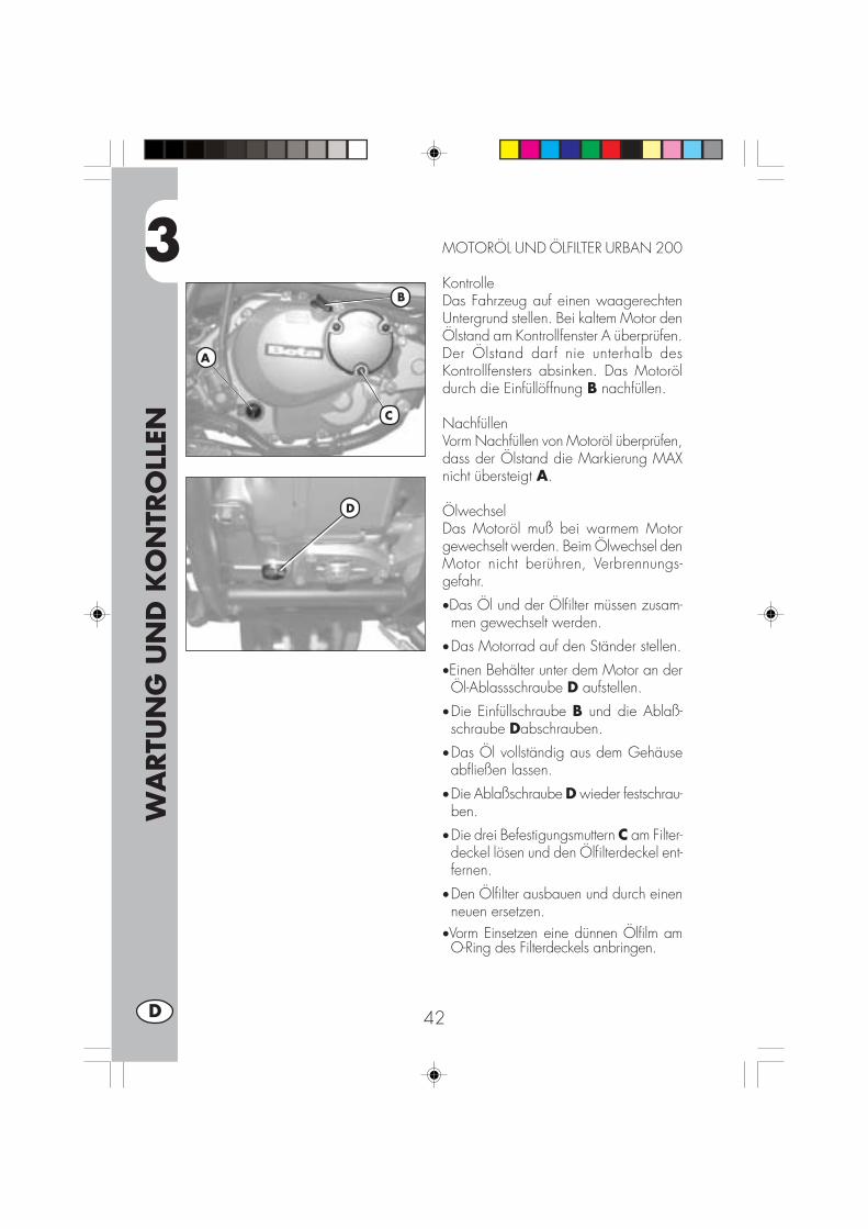
3
WA
RTU
NG
UN
D K
ON
TRO
LLEN
42D
MOTORÖL UND ÖLFILTER URBAN 200
KontrolleDas Fahrzeug auf einen waagerechtenUntergrund stellen. Bei kaltem Motor denÖlstand am Kontrollfenster A überprüfen.Der Ölstand darf nie unterhalb desKontrollfensters absinken. Das Motoröldurch die Einfüllöffnung B nachfüllen.
NachfüllenVorm Nachfüllen von Motoröl überprüfen,dass der Ölstand die Markierung MAXnicht übersteigt A.
ÖlwechselDas Motoröl muß bei warmem Motorgewechselt werden. Beim Ölwechsel denMotor nicht berühren, Verbrennungs-gefahr.
•Das Öl und der Ölfilter müssen zusam-men gewechselt werden.
•Das Motorrad auf den Ständer stellen.
•Einen Behälter unter dem Motor an derÖl-Ablassschraube D aufstellen.
•Die Einfüllschraube B und die Ablaß-schraube Dabschrauben.
•Das Öl vollständig aus dem Gehäuseabfließen lassen.
•Die Ablaßschraube D wieder festschrau-ben.
•Die drei Befestigungsmuttern C am Filter-deckel lösen und den Ölfilterdeckel ent-fernen.
•Den Ölfilter ausbauen und durch einenneuen ersetzen.
•Vorm Einsetzen eine dünnen Ölfilm amO-Ring des Filterdeckels anbringen.
B
A
C
D

3
WA
RTU
NG
UN
D K
ON
TRO
LLEN
43 D
•Die Feder und den O-Ring anbringen undden Filterdeckel mit den drei Muttern be-festigen C.
•Die richtige Ölmenge einfüllen:- Ölwechsel 850 ml- mit Filterwechsel 950 ml- Revision 1300 ml
•Die Öl-Einfüllschraube B wieder schlie-ßen.
•Den Motor starten und einige Minutenlaufen lassen.
•Den Motor ausschalten und ungefähr eineMinute warten, anschließend den Füll-stand kontrollieren und gegebenenfallsnachfüllen, ohne dabei den Max-Füllstandam Schauglas A zu überschreiten.
Anmerkung:Nach den ersten 1.000 gefahrenen Kilo-metern muß das Motoröl gewechselt wer-den. Anschließend muß das Motoröl alle5.000 km15 Monate, (siehe Tabelle aufSeite 57). Ausschließlich die in der Tabelleauf Seite 37 angegebenen Schmiermittelverwenden.Der Ölfilter muß beim ersten Ölwechselausgetauscht werden. Anschließend denÖlfilter alle 10.000 km (30 Monate).
Hinweis:Das Altöl muß entsprechend der gesetzli-chen Umweltvorschriften entsorgt werden.

3
WA
RTU
NG
UN
D K
ON
TRO
LLEN
44D
MOTORÖL UND ÖLFILTER URBAN 125KontrolleDas Fahrzeug auf einen waagerechtenUntergrund stellen. Bei kaltem Motor DenÖlstand prüfen.NachfüllenZum Nachfüllen Öl über die EinfüllöffnungA einfüllen.ÖlwechselDas Motoröl muß bei warmem Motor ge-wechselt werden. Beim Ölwechsel denMotor nicht berühren, Verbrennungsgefahr.•Der Ölfilter muß beim Ölwechsel eben-falls ausgetauscht werden.
•Das Motorrad auf den Ständer stellen.•Einen Behälter zum Auffangen des Alt-öls unter dem Motor aufstellen.
•Die Einfüllschraube A und die Ablaß-schraube B abschrauben.
•Das Öl vollständig aus dem Gehäuseabfließen lassen.
•Die Öl-Ablassschraube B wieder schließen.•1000 cm3 Öl einfüllen.•Die Öl-Einfüllschraube (A) wieder schlie-ßen.
ACHTUNG:Heißes Öl kann schwere Verbrühungenverursachen.Anmerkung:Beim Motor URBAN125 befindet sich derRotations-Ölfilter an der Kurbelwelle aufder Kupplungsseite. Zum Wechseln wen-den Sie sich bitte an einen Betamotor-Vertragshändler.Anmerkung:Nach den ersten 500 km muss das Motorölgewechselt werden. Für das Wechseln dieAngaben aus der Tabelle auf Seite 57 be-achten. Die auf Seite 37 angegebenen emp-fohlenen Schmiermittel benutzen.
Hinweis:Das Altöl muß entsprechend der gesetzli-chen Umweltvorschriften entsorgt werden.
A
B

3
WA
RTU
NG
UN
D K
ON
TRO
LLEN
45 D
ÖLDAMPF-SAMMELLEITUNG
Die Öldampf-Sammelleitung A befindet sich auf derlinken Fahrzeugseite in der Nähe des Stoßdämp-fers. Sie wird aus der Unterseite des Filtergehäusesherausgeführt und sammelt die Motoröldämpfe.Sobald sich Öl in dieser Leitung befindet, muß diesegeleert werden. Dazu den Verschluß am unterenEnde der Leitung abnehmen und das ausfließendeÖl bzw. Benzin- Ölgemisch in einem geeignetenBehälter auffangen. Das Altöl muß entsprechendder gesetzlichen Umweltvorschriften entsorgt werden.Anmerkung: Die Leitung muß alle 3.000km entleert werden.
HINWEIS:Das Altöl muß entsprechend der gesetzli-chen Umweltvorschriften entsorgt werden.
BREMSFLÜSSIGKEIT, ENTLÜFTEN DERBREMSENVorderradbremseDen Bremsflüssigkeit am Kontrollfenster B über-prüfen. Der Bremsflüssigkeitsstand darf nie un-ter die entsprechende Markierung amKontrollfenster B abfallen. Zum Nachfüllen derBremsflüssigkeit die beiden Schrauben C lö-sen, den Deckel D anheben und die Brems-flüssigkeit einfüllen.HinterradbremseDen Bremsflüssigkeitsstand über das SchauglasE kontrollieren. Der Mindest-Bremsflüssigkeits-stand darf nie unterhalb der Markierung amSchauglas E liegen. Zum Nachfüllen vonBremsflüssigkeit die beiden Schrauben F ab-schrauben, den Deckel G anheben und Brems-flüssigkeit einfüllen.
ACHTUNG:Gibt der Bremshebel beim Bremsen
nach, befindet sich wahrscheinlich Luft in derBremsanlage. Wenden Sie sich bitte umge-hend an den Kundendienst. In diesem Fall mussder Bremskreis entlüftet werden.Anmerkung:Zum Wechseln der Bremsflüssigkeit bittedie Angaben in der Tabelle aus Seite 57einhalten. Die in der Tabelle auf Seite 37angegebenen Schmiermittel und Flüssigkei-ten verwenden.
A
D
C
B
F
EG

3
WA
RTU
NG
UN
D K
ON
TRO
LLEN
46D
Entlüften der VorderradbremseZum Entlüften der Vorderradbremse wiefolgt vorgehen:•Die Gummikappe A vom Entlüftungsven-til B abnehmen.
•Den Deckel vom Bremsflüssigkeits-behälter abnehmen.
•Einen Schlauch auf das EntlüftungsventilB aufsetzen, das andere Schlauchen-de in einen Behälter leiten.
•Das Ventil B (bei gezogenem Bremshebel)losschrauben und mit dem Bremshebelsolange pumpen, bis nur noch Brems-flüssigkeit ohne Luftblasen austritt. Wichtig,bei dieser Arbeit den Bremshebel niemalsvollständig loslassen und ständig Brems-flüssigkeit nachfüllen, um die austretendeBremsflüssigkeit zu ersetzen.
•Das Entlüftungsventil wieder festschraubenund den Schlauch abnehmen.
•Die Gummikappe wieder aufsetzen.
Entlüften der HinterradbremseZum Entlüften der Hinterradbremse wiefolgt vorgehen:•Die Gummikappe D.•Den Deckel vom Bremsflüssigkeits-behälter abnehmen.
•Einen Schlauch auf das Entlüftungsven-til F aufsetzen, das andere Schlauchen-de in einen Behälter leiten.
•Das Ventil F (bei gezogenem Bremshebel)losschrauben und mit dem Bremshebelsolange pumpen, bis nur noch Brems-flüssigkeit ohne Luftblasen austritt. Wichtig,bei dieser Arbeit den Bremshebel niemalsvollständig loslassen und ständig Brems-flüssigkeit nachfüllen, um die austretendeBremsflüssigkeit zu ersetzen.
•Das Entlüftungsventil wieder festschraubenund den Schlauch abnehmen.
•Die Gummikappe wieder aufsetzen.
DF
A
B
C
E

3
WA
RTU
NG
UN
D K
ON
TRO
LLEN
47 D
GABELÖL
Rechter GabelschaftDie Beschreibung zum Wechseln desGabelöl hat rein informativen Charakter.Wir empfehlen Ihnen sich zum Austauschdes Gabelöl an den BETAMOTOR-Kun-dendienst zu wenden.Zum Austausch des Gabelöls wie folgtvorgehen:
1) Die Befestigungsschraube A desGabelschafts lösen.
2) Die untere Verschlußschraube(Inbusschraube) und den oberen Ver-schluß B entfernen.
3) Das Gabelöl vollständig ausfließenlassen.
4) Die untere Verschlußschraube wiederfestschrauben.
5) Das in der Tabelle auf Seite 37 ange-gebenen Gabelöl einfüllen.
6) Den oberen Verschluß B wieder schlie-ßen.
7) Die Schraube A wieder festziehen.
Anmerkung: Das Verfahren zum Ölwech-sel gilt für den rechten und linken Schaft.
A
B

3
WA
RTU
NG
UN
D K
ON
TRO
LLEN
48D
LUFTFILTER
Die Filtereinheit A ist zugänglich, wenndie Sitzbank, wie im Abschnitt “Ausbauder Karosserie” auf Seite 52 beschrieben,abmontiert werden.•Die Schraube C abschrauben und denDeckel B entfernen.
• Den Batteriehalter anheben (siehe Ab-bildung).
• Die Filterhalterung D aushaken.• Die Filtereinheit A entfernen.• Die Filterhalterung D herausziehen unddas Filterelement entfernen.
•Mit Wasser und Seife waschen.•Trocknen.•Mit Filteröl tränken und überschüssigesÖl ausdrücken.
•Gegebenenfalls auch das Innere desFiltergehäuses reinigen.
•Beim Einbau des Filters darauf achten,dass die Gummidichtung den Filter her-metisch abschließt.
Anmerkung: Ist der Filter sehr schmutzig,zuerst mit einem Spezial-Reinigungsmittelreinigen und dann mit Wasser und einemmilden Waschmittel waschen.Ein beschädigter Filter muß sofort ausge-wechselt werden.
ACHTUNG:Nach jeder Filterreinigung daraufachten, dass keine Gegenstände
im Filtergehäuse vergessen worden sind.
Der Filter muß nach jedem Geländeein-satz des Fahrzeugs gereinigt werden.
D
A
B C
DA

3
WA
RTU
NG
UN
D K
ON
TRO
LLEN
49 D
ZÜNDKERZE
Um Verbrennungen zu ver-meiden, müssen bei dieserArbeit Schutzhandschuhegetragen werden.
Eine gut gepflegte Zündkerze senkt denBenzinverbrauch und sorgt für einen op-timalen Betrieb des Motors.Die Zündkerze sollte möglichst bei war-mem (und natürlich abgestelltem) Motorausgewechselt werden, da die Schlacke-ablagerungen und die Verfärbung desIsolationsteils wichtige Hinweise auf dieVerbrennung, Schmierung und den allge-meinen Motorzustand geben.Ist das Isolationsteil weiß verfärbt, kann dieGemischbildung zu „mager“ sein. Umge-kehrt, ist das Isolationsteil grün verfärbt,kann die Gemischbildung zu „fett“ sein.Bei einer richtigen Gemischbildung ist dasIsolationsteil nussbraun.Zur Kontrolle der Zündkerze den Kerzen-stecker abziehen und die Zündkerze mitdem mitgelieferten Kerzenstecker los-schrauben.Die Kerzenelektroden gründlich mit einerMetallbürste reinigen. Anschließend dieZündkerze mit Druckluft ausblasen, um zuvermeiden, dass eventuelle Rückstände inden Motor gelangen können.Mit einer Schublehre den Elektrodenab-stand messen. Der Elektrodenabstandmuß 0,6 - 0,7 mm betragen. Bei abwei-chenden Werten kann der richtigeElektrodenabstand durch vorsichtiges Bie-gen der äußeren Elektrode hergestelltwerden.Das Isolierteil auf Risse und die Elektro-den auf Rostbildung überprüfen. Gege-
benenfalls die Zündkerze auswechseln.Anmerkung:Für die Kontrolle die Angaben auf Seite57 einhalten.
Anmerkung:Das Kerzengewinde (bei kaltem Motor)schmieren und die Kerze zunächst vonHand einschrauben, erst anschließend mitdem Kerzenschlüssel festziehen.
Anmerkung:•Wir raten Ihnen ausschließlich Kerzenzu verwenden:
URBAN 200 = NGK DR8 EAURBAN 125 = NGK CR7 HSA

3
WA
RTU
NG
UN
D K
ON
TRO
LLEN
50D
VORDERRADBREMSE
KontrolleUm den Verschleißzustand der Vorderrad-bremse zu überprüfen, reicht es aus denBremssattel von der Vorderseite her zubetrachten. Von dort aus sieht man diebeiden Bremsbeläge, die eine Belag-stärke von mindestens 2 mm haben müs-sen. Bei geringerer Belagstärke müssendie Bremsbeläge sofort ausgewechseltwerden (siehe Abschnitt 5 “Auswechseln”auf Seite 66).
Anmerkung:Bei den Kontrollen müssen die in der Ta-belle auf Seite 302 angegebenen Zeit-räume eingehalten werden.
HINTERRADBREMSE
KontrolleUm den Verschleißzustand der Vorderrad-bremse zu überprüfen, reicht es aus denBremssattel von der oben her zu betrach-ten. Von dort aus sieht man die beidenBremsbeläge, die eine Belagstärke vonmindestens 2 mm haben müssen. Bei ge-ringerer Belagstärke müssen die Bremsbe-läge sofort ausgewechselt werden (sieheAbschnitt 5 “Auswechseln” auf Seite 66).
Anmerkung:Bei den Kontrollen müssen die in der Ta-belle auf Seite 57 angegebenen Zeiträu-me eingehalten werden.
2 mm
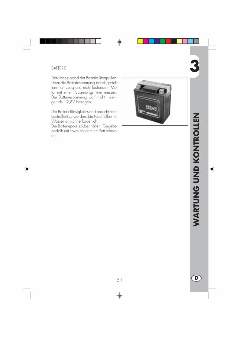
3
WA
RTU
NG
UN
D K
ON
TRO
LLEN
51 D
BATTERIE
Den Ladezustand der Batterie überprüfen.Dazu die Batteriespannung bei abgestell-tem Fahrzeug und nicht laufendem Mo-tor mit einem Spannungsmeter messen.Die Batteriespannung darf nicht weni-ger als 12,8V betragen.
Der Batterieflüssigkeitsstand braucht nichtkontrolliert zu werden. Ein Nachfüllen mitWasser ist nicht erforderlich.Die Batteriepole sauber halten. Gegebe-nenfalls mit etwas säurefreiem Fett schmie-ren.
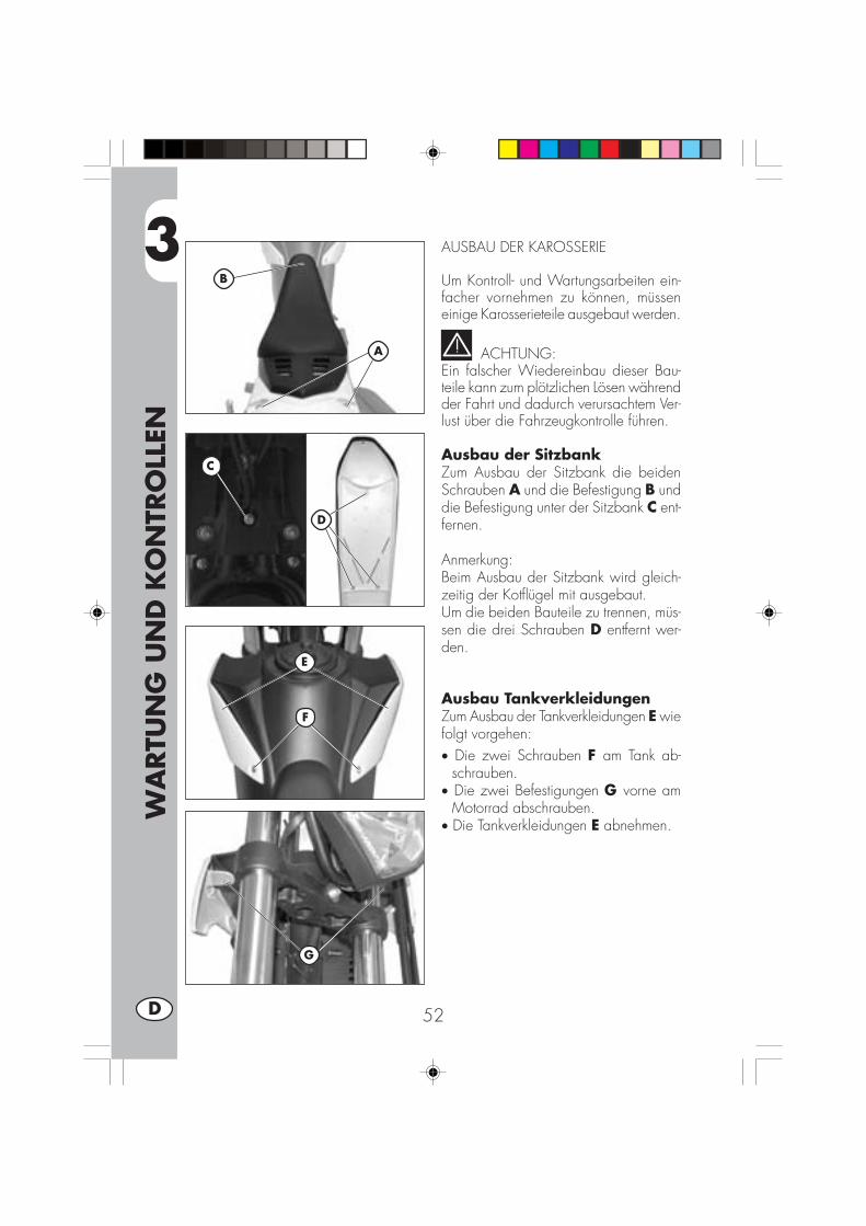
3
WA
RTU
NG
UN
D K
ON
TRO
LLEN
52D
AUSBAU DER KAROSSERIE
Um Kontroll- und Wartungsarbeiten ein-facher vornehmen zu können, müsseneinige Karosserieteile ausgebaut werden.
ACHTUNG:Ein falscher Wiedereinbau dieser Bau-teile kann zum plötzlichen Lösen währendder Fahrt und dadurch verursachtem Ver-lust über die Fahrzeugkontrolle führen.
Ausbau der SitzbankZum Ausbau der Sitzbank die beidenSchrauben A und die Befestigung B unddie Befestigung unter der Sitzbank C ent-fernen.
Anmerkung:Beim Ausbau der Sitzbank wird gleich-zeitig der Kotflügel mit ausgebaut.Um die beiden Bauteile zu trennen, müs-sen die drei Schrauben D entfernt wer-den.
Ausbau TankverkleidungenZum Ausbau der Tankverkleidungen E wiefolgt vorgehen:• Die zwei Schrauben F am Tank ab-
schrauben.• Die zwei Befestigungen G vorne am
Motorrad abschrauben.• Die Tankverkleidungen E abnehmen.
F
E
G
A
B
C
D
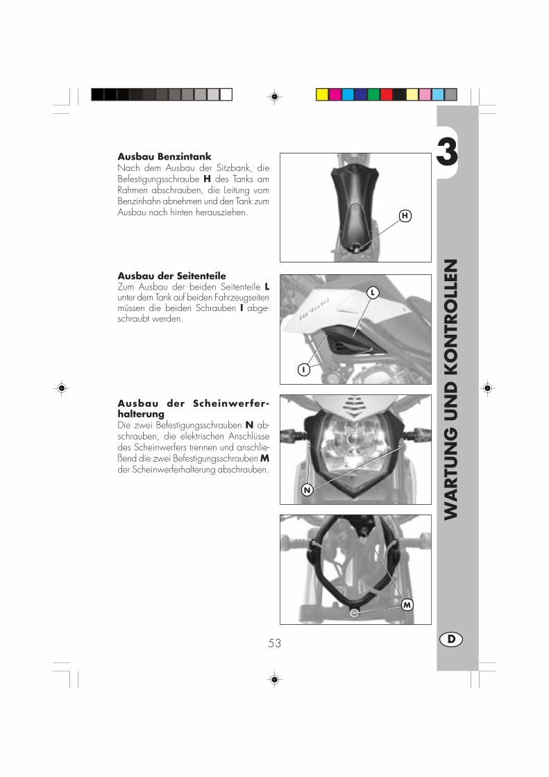
3
WA
RTU
NG
UN
D K
ON
TRO
LLEN
53 D
Ausbau BenzintankNach dem Ausbau der Sitzbank, dieBefestigungsschraube H des Tanks amRahmen abschrauben, die Leitung vomBenzinhahn abnehmen und den Tank zumAusbau nach hinten herausziehen.
Ausbau der SeitenteileZum Ausbau der beiden Seitenteile Lunter dem Tank auf beiden Fahrzeugseitenmüssen die beiden Schrauben I abge-schraubt werden.
Ausbau der Scheinwerfer-halterungDie zwei Befestigungsschrauben N ab-schrauben, die elektrischen Anschlüssedes Scheinwerfers trennen und anschlie-ßend die zwei Befestigungsschrauben Mder Scheinwerferhalterung abschrauben.
H
L
I
N
M
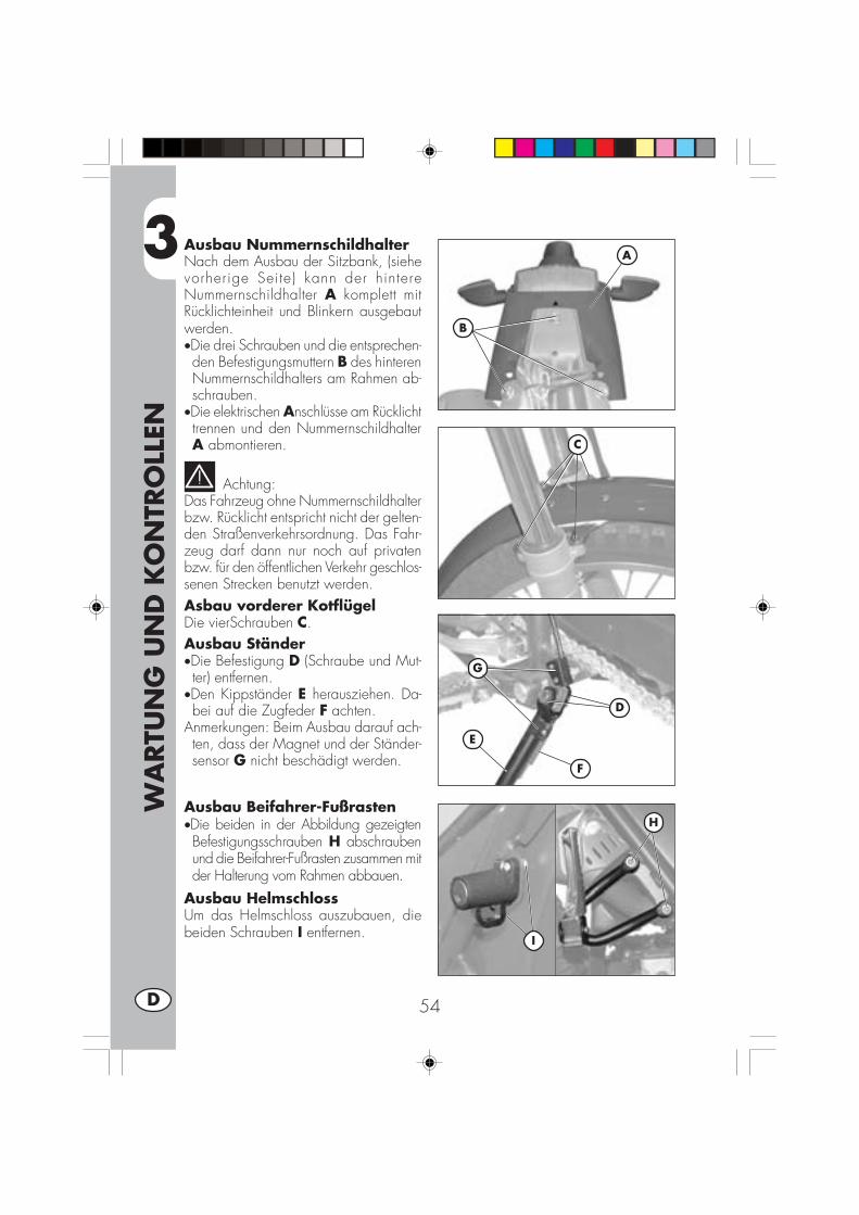
3
WA
RTU
NG
UN
D K
ON
TRO
LLEN
54D
A
B
C
E
D
F
G
H
I
Ausbau NummernschildhalterNach dem Ausbau der Sitzbank, (siehevorherige Seite) kann der hintereNummernschildhalter A komplett mitRücklichteinheit und Blinkern ausgebautwerden.•Die drei Schrauben und die entsprechen-den Befestigungsmuttern B des hinterenNummernschildhalters am Rahmen ab-schrauben.
•Die elektrischen Anschlüsse am Rücklichttrennen und den NummernschildhalterA abmontieren.
Achtung:Das Fahrzeug ohne Nummernschildhalterbzw. Rücklicht entspricht nicht der gelten-den Straßenverkehrsordnung. Das Fahr-zeug darf dann nur noch auf privatenbzw. für den öffentlichen Verkehr geschlos-senen Strecken benutzt werden.Asbau vorderer KotflügelDie vierSchrauben C.Ausbau Ständer•Die Befestigung D (Schraube und Mut-ter) entfernen.
•Den Kippständer E herausziehen. Da-bei auf die Zugfeder F achten.
Anmerkungen: Beim Ausbau darauf ach-ten, dass der Magnet und der Ständer-sensor G nicht beschädigt werden.
Ausbau Beifahrer-Fußrasten•Die beiden in der Abbildung gezeigtenBefestigungsschrauben H abschraubenund die Beifahrer-Fußrasten zusammen mitder Halterung vom Rahmen abbauen.
Ausbau HelmschlossUm das Helmschloss auszubauen, diebeiden Schrauben I entfernen.

3
WA
RTU
NG
UN
D K
ON
TRO
LLEN
55 D
Austausch des KettenritzelsDie Beschreibung zum Wechsel des Ket-tenritzels hat rein informativen Charakter.Für diese Arbeit sollten Sie sich an eineBETAMOTOR-Vertragswerkstatt wenden.
•Zum Lockern der Kette die Muttern I (aufbeiden Seiten) und die Ketten-Stellvor-richtung L lösen und das Rad bis zumAnschlag nach vorne schieben.
•Die drei Befestigungsschrauben M derAbdeckung abschrauben ( 2 Schraubenfür Modelle URBAN125).
•Die Kette aus dem Kettenritzel aushän-gen.
• IDen ersten Gang einlegen und dieBefestigungsmutter N des Ritzels (fürURBA200) und die beiden Befestigun-gen P (für URBAN125) gegen den Uhr-zeigersinn lösen..
•Das Kettenritzel austauschen.•Beim Wiedereinbau in umgekehrterReihenfolge wie beim Ausbau vorgehen.
Befestigungszapfen Gabel•Den Gummiverschluss oberhalb derrechten Fahrer-Fußraste entfernen.
•Die darunter liegende Mutter lösen undden Zapfen von der gegenüber liegen-den Seite her herausziehen.
Hinweis:Der Abbau des Nummernschildhalterkomplett mit Rücklicht ist nur auf Privat-gelände oder Rennpisten gestattet.
Anmerkung:Wir empfehlen das Ritzel zusammen mit dergesamten Antriebseinheit auszuwechseln.
I
M
O
N
L
M
P
O
URBAN200 URBAN125
URBAN200
URBAN125

3
WA
RTU
NG
UN
D K
ON
TRO
LLEN
56D
FAHRZEUGPFLEGE UND KONTROLLEN
Zum Aufweichen von Schmutz und Schlamm auf den lackierten Oberflächen einenWasserstrahl mit niedrigem Druck benutzen. Ist der Schmutz aufgeweicht, muß er miteinem weichen Schwamm mit viel Wasser und Autoshampoo (2-4% Shampoo imWasser) entfernt werden. Anschließend mit viel klarem Wasser nachspülen und miteinem Wildledertuch abledern. Den Motor außen mit Petroleum, Pinsel und reinenLappen säubern. Petroleum schädigt den Lack. Eine Glanzbehandlung darf erstnach erfolgtem Waschen durchgeführt werden.
Die Reinigungsmittel verschmutzen das Wasser. Daher muß die Fahrzeug-reinigung an Orten stattfinden, die mit einer Anlage zur Waschwasserrück-
führung und Aufbereitung ausgestattet sind.
Das Fahrzeug nie in praller Sonne waschen. Dies gilt besonders im Sommer,wenn die Karosserie noch warm ist und das Shampoo noch vor dem abspü-
len antrocknen kann. Dies kann Schäden an der Karosserie verursachen. BenutzenSie nie in Benzin oder Öl getränkte Lappen zur Reinigung lackierter Fahrzeugteile,um Glanzverluste und den Verlust mechanischer Eigenschaften zu vermeiden.
Ein eventueller Einsatz von Wasserstrahl-Reinigungsgeräten kann Schäden anden Instrumenten verursachen. Wir empfehlen daher den Wasserstrahl nicht
direkt auf die elektrischen Bauteile zu richten. Das gilt speziell für das LCD-Display.
KONTROLLEN NACH DER FAHRZEUGPFLEGE
Nach der Fahrzeugpflege sollten folgende Kontrollen durchgeführt werden:
•Den Luftfilter reinigen (siehe Anleitung aus Seite 48).•Die Kette schmieren.
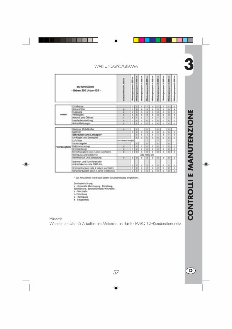
3
CO
NTR
OLL
I E
MA
NU
TEN
ZIO
NE
57 D
WARTUNGSPROGRAMM
Hinweis:Wenden Sie sich für Arbeiten am Motorrad an das BETAMOTOR-Kundendienstnetz.

3
CO
NTR
OLL
I E
MA
NU
TEN
ZIO
NE
58D
LÄNGERES STILLLEGEN DES FAHRZEUGS
Soll der Motorroller längere Zeit stillgelegt werden, z. B. während des Winters,müssen zur richtigen Aufbewahrung einige einfache Vorkehrungen getroffen wer-den:•Das Fahrzeug und alle Fahrzeugteilegründlich reinigen.
•Den Reifendruck um ungefähr 30% sen-ken, die Räder möglichst vom Bodenanheben.
•Die Zündkerze ausbauen und einigeTropfen Motoröl in die Kerzenöffnunggeben. Den Kickstarter (wo vorhanden)betätigen und den Motor einige Umdre-hungen ausführen lassen. Die Zündker-ze wieder einschrauben.
•Die elektronische Diebstahlsicherung(wenn vorhanden) abklemmen.
•Außer an Gummiteilen und Bremsen aufalle nicht lackierten Fahrzeugteile einedünne Schicht Silikonöl auftragen.
•Die Batterie ausbauen und an einemTrockenen Ort aufbewahren. Die Batte-rie muß einmal im Monat aufgeladenwerden.
•Zum Schutz gegen Staub den Motorrol-ler mit einer Schutzplane bedecken.
•Die Vergaserwanne durch die Ablaßschraube A entleeren. Den abgelassenen Kraft-stoff in einem geeigneten Behälter auffangen und in den Tank füllen. Keinen Kraft-stoff in die Umwelt gelangen lassen.
•Die Ablaßschraube wieder festziehen.
NACH LÄNGEREM STILLEGEN DES FAHRZEUGS
•Die Batterie wieder einbauen.•Den Reifendruck wieder herstellen.•Den Anzug aller wichtigen Schrauben überprüfen.
ANMERKUNG:Der richtige Anzug aller Schrauben muß in regelmäßigen Abständen überprüft wer-den.
•Das erstmalige Starten muß mit dem Kickstarter erfolgen.
A
A
URBAN200
URBAN125
4
EIST
ELLU
NG
EN
59 D
INHALTSVERZEICHNIS
KAPITEL 4 EINSTELLUNGEN
Einstellen der Bremsen
Einstellen der Kupplung
Leerlaufeinstellung
Einstellen des Gaszuges
Kontrolle und Einstellen des Lenkerspiels
Spannen der Kette
Einstellen des Scheinwerfers

4
EIST
ELLU
NG
EN
60D
EINSTELLEN DER BREMSEN
VorderradbremseDie Vorderradbremse ist eine Scheiben-bremse mit hydraulischer Betätigung. Die-se Bremse muss nicht nachgestellt wer-den.
HinterradbremseDie Hinterradbremse ist eine Scheiben-bremse mit hydraulischer Betätigung. Die-se Bremse muss nicht nachgestellt wer-den.
EINSTELLUNG DER KUPPLUNG
Die einzige Einstellung an der Kupplungist die Einstellung der Position desKupplungshebels E.Diese Einstellung erfolgt über die Ein-stellvorrichtung D.Bei Verstellen der Einstellschraube mußnach erfolgter Einstellung unbedingt dieKontermutter F in der gewünschten Stel-lung festgezogen werden.
Anmerkung:Der Kupplungshebel muß ein Spiel zwi-schen 0,4 und 0,6 mm haben.
FD E

4
EIST
ELLU
NG
EN
61 D
LEERLAUFEINSTELLUNG URBAN200Um den Leerlauf richtig einzustellen, mußdiese Arbeit bei warmem Motor ausge-führt werden. Einen elektronischen Dreh-zahlmesser an das Zündkabel anschlie-ßen. Die Leerlaufdrehzahl über die Leer-lauf-Einstellschraube A auf einen Wert von1.400 ± 100 U/min einstellen.
LEERLAUFEINSTELLUNG URBAN125Um den Leerlauf richtig einzustellen, mußdiese Arbeit bei warmem Motor ausge-führt werden. Einen elektronischen Dreh-zahlmesser an das Zündkabel anschlie-ßen.Mit einem Schraubenzieher über die Leer-lauf-Einstellschraube (C) die Leerlauf-drehzahl auf einen Wert von 1900 U/Min einstellen.
EINSTELLUNG BENZINFLUSSURBAN125/200ZUR EINSTELLUNG DES BENZINFLUSSES DIE
SCHRAUBE D VON VOLLSTÄNDIG GESCHLOSSENER
POSITION UM 1 _ UMDREHUNGEN ÖFFNEN.Standard-Regulierung der Eistellschraube:Von ganz geschlossen (Uhrzeigersinn) dieEistellschraube um 1,5 Drehungen lockern
EINSTELLEN DES GASZUGESHat der Gasgriff ein Spiel von mehr als3 mm (gemessen am oberen Rand desGasgriffs), muß das Spiel über die Ein-stellvorrichtung B am Gasgriff eingestelltwerden.
B
A
CD
URBAN125
D
URBAN200

4
EIST
ELLU
NG
EN
62D
KONTROLLE UND EINSTELLEN DESLENKERSPIELS
Das Spiel am Lenkrohr regelmäßig über-prüfen. Dazu das Vorderrad bremsen unddas Fahrzeug wie in der Abbildung ge-zeigt nach vorne und hinten bewegen.Wird ein Spiel am Lenkrohr festgestellt,muß wie folgt vorgegangen werden:
•Die vier Schrauben A abschrauben.
•Den Lenker B herausziehen. Dabei be-sonders auf die Bügelschrauben C ach-ten.
•Die Mutter D lösen.
• Die zwei Schrauben F.
•Das Spiel über die Nutmutter E einstel-len.
Zum Befestigen in umgekehrter Reihen-folge vorgehen.
Anmerkung:Ist die Einstellung richtig ausgeführt wor-den, ist das Spiel vollständig beseitigt,das Drehen des Lenkers erfolgt leicht-gängig und gleichmäßig. Die Einbau-stellung der Bügelschrauben überprüfen,da diese die Lenkereinstellung ändernkönnen
Anmerkung:Für diese Arbeit sollten Sie sich an eineBetamotor-Vertragswerkstaff wenden.
B
D
E C
A
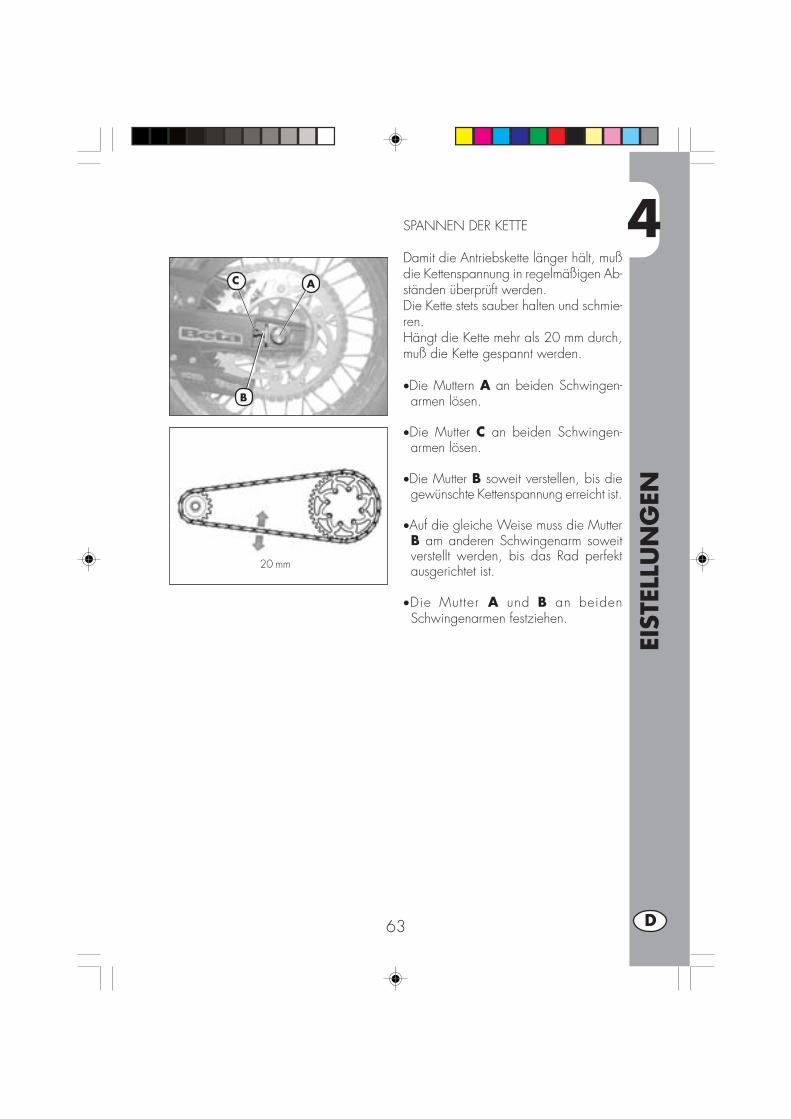
4
EIST
ELLU
NG
EN
63 D
SPANNEN DER KETTE
Damit die Antriebskette länger hält, mußdie Kettenspannung in regelmäßigen Ab-ständen überprüft werden.Die Kette stets sauber halten und schmie-ren.Hängt die Kette mehr als 20 mm durch,muß die Kette gespannt werden.
•Die Muttern A an beiden Schwingen-armen lösen.
•Die Mutter C an beiden Schwingen-armen lösen.
•Die Mutter B soweit verstellen, bis diegewünschte Kettenspannung erreicht ist.
•Auf die gleiche Weise muss die MutterB am anderen Schwingenarm soweitverstellt werden, bis das Rad perfektausgerichtet ist.
•Die Mutter A und B an beidenSchwingenarmen festziehen.
20 mm
B
C A

4
EIST
ELLU
NG
EN
64D
EINSTELLEN DES SCHEINWERFERS
•Die Einstellung des Scheinwerfers erfolgt von Hand, nachdem die beidenInbusschrauben an den Scheinwerferseiten gelöst wurden.
•Der Scheinwerfer muß in regelmäßigen Abständen eingestellt werden. Der Schein-werfer kann nur in der Höhe verstellt werden.
•Das Fahrzeug in einem Abstand von 10 auf einem ebenen Untergrund vor eineWand stellen (nicht auf den Ständer stellen).
•Den Abstand der Scheinwerfermitte vom Boden messen und die Wand in einemAbstand von 9/10 des gemessenen Wertes markieren.
•Das Fahrlicht einschalten, sich auf das Motorrad setzen und überprüfen, dass sichder Scheinwerferstrahl knapp unterhalb der Wandmarkierung befindet.
9/10
h
10 m
h
AA
5
AU
STA
USC
HEN
/ A
USW
ECH
SELN
VO
N T
EILE
N
65 D
INHALTSVERZEICHNIS
KAPITEL 5 AUSTAUSCHEN/ AUSWECHSELN VON TEILEN
Auswechseln der Bremsbeläge
Auswechseln der Scheinwerferlampen
Auswechseln der Rücklichtlampe
Auswechseln der Blinkerlampen
Auswechseln der Armaturenbrettlampen
Charakteristische Lampen
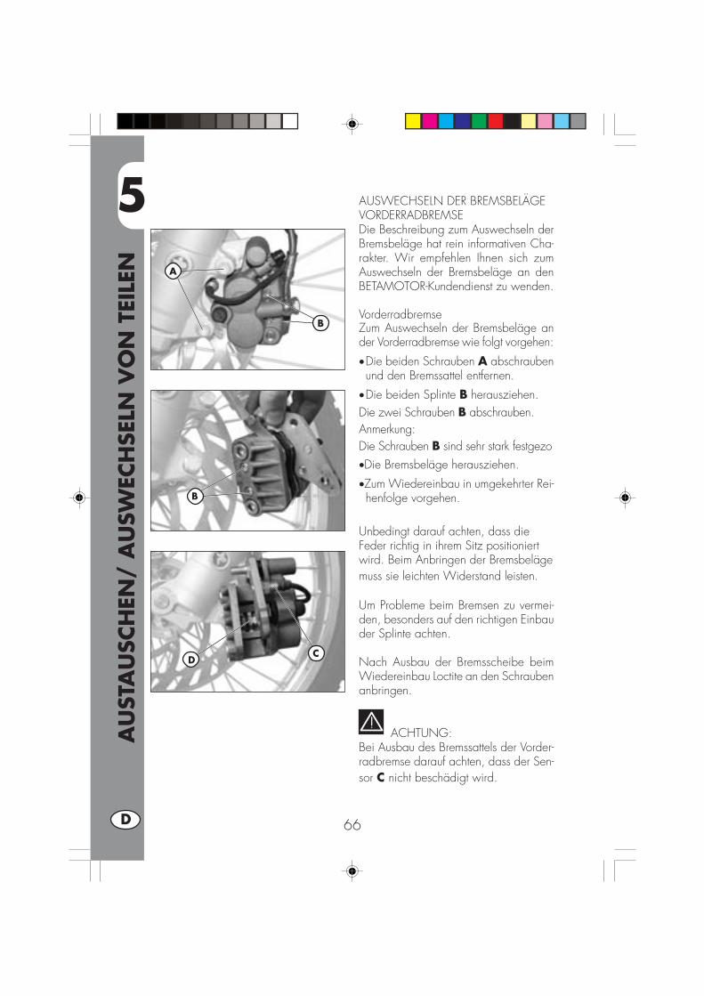
5
AU
STA
USC
HEN
/ A
USW
ECH
SELN
VO
N T
EILE
N
66D
AUSWECHSELN DER BREMSBELÄGEVORDERRADBREMSEDie Beschreibung zum Auswechseln derBremsbeläge hat rein informativen Cha-rakter. Wir empfehlen Ihnen sich zumAuswechseln der Bremsbeläge an denBETAMOTOR-Kundendienst zu wenden.
VorderradbremseZum Auswechseln der Bremsbeläge ander Vorderradbremse wie folgt vorgehen:
•Die beiden Schrauben A abschraubenund den Bremssattel entfernen.
•Die beiden Splinte B herausziehen.Die zwei Schrauben B abschrauben.Anmerkung:Die Schrauben B sind sehr stark festgezo•Die Bremsbeläge herausziehen.
•Zum Wiedereinbau in umgekehrter Rei-henfolge vorgehen.
Unbedingt darauf achten, dass dieFeder richtig in ihrem Sitz positioniertwird. Beim Anbringen der Bremsbelägemuss sie leichten Widerstand leisten.
Um Probleme beim Bremsen zu vermei-den, besonders auf den richtigen Einbauder Splinte achten.
Nach Ausbau der Bremsscheibe beimWiedereinbau Loctite an den Schraubenanbringen.
ACHTUNG:Bei Ausbau des Bremssattels der Vorder-radbremse darauf achten, dass der Sen-sor C nicht beschädigt wird.
CD
A
B
B

5
AU
STA
USC
HEN
/ A
USW
ECH
SELN
VO
N T
EILE
N
67 D
HinterradbremseZum Auswechseln der Bremsbeläge ander Hinterradbremse wie folgt vorgehen:•Den Sicherungsstift A entfernen.•Den Haltebolzen der Bremsbeläge Babschrauben.
•Die Bremsbeläge C entfernen.•Beim Einbau in umkehrter Reihenfolgevorgehen. Sorgfältig darauf achten,dass die Bremsbeläge wieder richtig inihren Sitz eingesetzt werden.
ANMERKUNG:Für einen Wechsel der Bremsbeläge soll-ten Sie sich immer an eine autorisierteBETAMOTOR-Werkstatt wenden.
A
B
C

5
AU
STA
USC
HEN
/ A
USW
ECH
SELN
VO
N T
EILE
N
68D
AUSWECHSELN DER SCHEINWERFER-LAMPEN
Zum Auswechseln der Scheinwerfer-lampen wie folgt vorgehen:•Die beiden Befestigungsschrauben Ader Scheinwerfereinheit an der Halte-rung entfernen.
•Den Kabelstecker B trennen.•Die Gummikappe C anheben.•Die Feder D aushaken.•Die durchgebrannte Lampe entfernenund eine neue Lampe einsetzen. BeimEinsetzen darauf achten, dass dasLampenglas nicht angefasst wird, um dieLampeneffizienz nicht zu beeinträchti-gen.
•Für die Standlichtlampe braucht nur dieKugel E abgezogen und die defekteLampe ausgewechselt zu werden.
•Zum Wiedereinbau in umgekehrter Rei-henfolge vorgehen.
Anmerkung:Alle Lampen müssen durch Lampen mitgleichen Eigenschaften ersetzt werden(Siehe Abschnitt “Technische Angaben zuden Lampen” auf Seite 76).
B
C
C
D
E
AA

5
AU
STA
USC
HEN
/ A
USW
ECH
SELN
VO
N T
EILE
N
69 D
AUSWECHSELN DER RÜCKLICHTLAMPEZum Auswechseln des Rücklichts A wiefolgt vorgehen:
•Den Nummernschildhalter wie im Kapi-tel “Ausbau der Karosserie” auf Seite60 beschrieben ausbauen.
•Alle elektrischen Anschlüsse trennen.•Die beiden Schrauben B unter demKotflügel abschrauben.
•Die defekte Rücklichteinheit A heraus-ziehen und durch eine neue ersetzen.
•Zum Wiedereinbau in umgekehrter Rei-henfolge vorgehen.
Anmerkung:Alle Lampen müssen durch Lampen mitgleichen Eigenschaften ersetzt werden(Siehe Abschnitt “Technische Angaben zuden Lampen” auf Seite 76).
AUSWECHSELN NUMMERNSCHILD-BELEUCHTUNG
Auswechseln der Lampe für dieNummernschildbeleuchtung wie folgtvorgehen:•Die Schraube C abschrauben.•Das Lampenglas D entfernen.•Die defekte Lampe aus der Kugelherausziehen und durch eine neueersetzen.
•Zum Wiedereinbau in umgekehrterReihenfolge vorgehen.
Anmerkung:Alle Lampen müssen durch Lampen mitgleichen Eigenschaften ersetzt werden(Siehe Abschnitt “Technische Angaben zuden Lampen” auf Seite 76).
A
B
CD
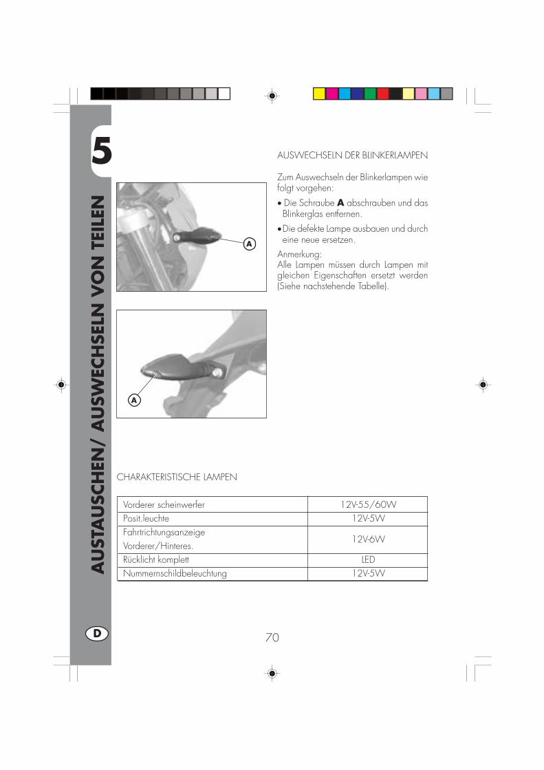
5
AU
STA
USC
HEN
/ A
USW
ECH
SELN
VO
N T
EILE
N
70D
A
A
AUSWECHSELN DER BLINKERLAMPEN
Zum Auswechseln der Blinkerlampen wiefolgt vorgehen:
• Die Schraube A abschrauben und dasBlinkerglas entfernen.
•Die defekte Lampe ausbauen und durcheine neue ersetzen.
Anmerkung:Alle Lampen müssen durch Lampen mitgleichen Eigenschaften ersetzt werden(Siehe nachstehende Tabelle).
Vorderer scheinwerfer 12V-55/60WPosit.leuchte 12V-5WFahrtrichtungsanzeigeVorderer/Hinteres.
12V-6W
Rücklicht komplett LEDNummernschildbeleuchtung 12V-5W
CHARAKTERISTISCHE LAMPEN

6
WA
S IS
T IM
NO
TFA
LL Z
U T
UN
71 D
INHALTSVERZEICHNIS
KAPITEL 6 WAS IST IM NOTFALL ZU TUN
ALPHABETISCHES INHALTSVERZEICHNIS
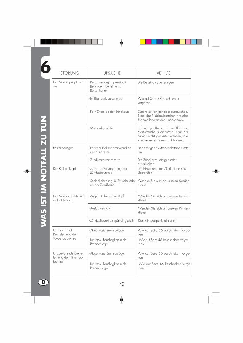
6
WA
S IS
T IM
NO
TFA
LL Z
U T
UN
72D
STÖRUNG URSACHE
Der Motor springt nichtan
ABHILFE
- Benzinversorgung verstopft(Leitungen, Benzintank,Benzinhahn)
- Luftfilter stark verschmutzt
- Kein Strom an der Zündkerze
- Motor abgesoffen
Die Benzinanlage reinigen
Wie auf Seite 48 beschriebenvorgehen
Zündkerze reinigen oder austauschen.Bleibt das Problem bestehen, wendenSie sich bitte an den Kundendienst
Bei voll geöffnetem Gasgriff einigeStartversuche unternehmen. Kann derMotor nicht gestartet werden, dieZündkerze ausbauen und trocknen
Fehlzündungen - Falscher Elektrodenabstand ander Zündkerze
Den richtigen Elektrodenabstand einstel-len
Der Kolben klopft - Zu starke Vorverstellung desZündzeitpunktes
- Schlackebildung im Zylinder oderan der Zündkerze
Die Einstellung des Zündzeitpunktesüberprüfen
Wenden Sie sich an unseren Kunden-dienst
Der Motor überhitzt undverliert Leistung
- Auspuff teilweise verstopft
- Auslaß verstopft
- Zündzeitpunkt zu spät eingestellt
Wenden Sie sich an unseren Kunden-dienst
Wenden Sie sich an unseren Kunden-dienst
Den Zündzeitpunkt einstellen
UnzureichendeBremsleistung derVorderradbremse
- Abgenutzte Bremsbeläge Wie auf Seite 66 beschrieben vorge-hen
Unzureichende Brems-leistung der Hinterrad-bremse
- Abgenutzte Bremsbeläge Wie auf Seite 66 beschrieben vorge-hen
Die Zündkerze reinigen oderaustauschen.
- Zündkerze verschmutzt
- Luft bzw. Feuchtigkeit in derBremsanlage
Wie auf Seite 46 beschrieben vorge-hen
- Luft bzw. Feuchtigkeit in derBremsanlage
Wie auf Seite 46 beschrieben vorge-hen
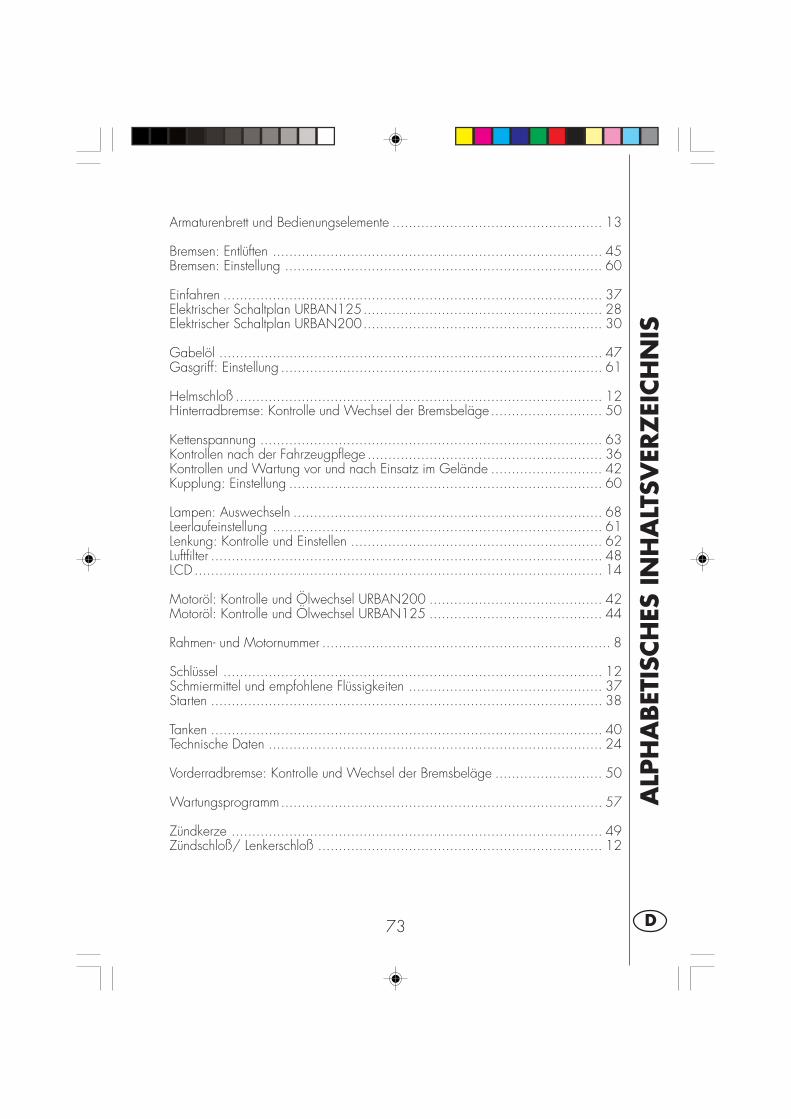
ALP
HA
BET
ISCH
ES IN
HA
LTSV
ERZ
EICH
NIS
73 D
Armaturenbrett und Bedienungselemente ................................................... 13
Bremsen: Entlüften ................................................................................ 45Bremsen: Einstellung ............................................................................. 60
Einfahren ............................................................................................ 37Elektrischer Schaltplan URBAN125.......................................................... 28Elektrischer Schaltplan URBAN200.......................................................... 30
Gabelöl ............................................................................................. 47Gasgriff: Einstellung .............................................................................. 61
Helmschloß ......................................................................................... 12Hinterradbremse: Kontrolle und Wechsel der Bremsbeläge ........................... 50
Kettenspannung ................................................................................... 63Kontrollen nach der Fahrzeugpflege ......................................................... 36Kontrollen und Wartung vor und nach Einsatz im Gelände ........................... 42Kupplung: Einstellung ............................................................................ 60
Lampen: Auswechseln ........................................................................... 68Leerlaufeinstellung ................................................................................ 61Lenkung: Kontrolle und Einstellen ............................................................. 62Luftfilter ............................................................................................... 48LCD ................................................................................................... 14
Motoröl: Kontrolle und Ölwechsel URBAN200 .......................................... 42Motoröl: Kontrolle und Ölwechsel URBAN125 .......................................... 44
Rahmen- und Motornummer ...................................................................... 8
Schlüssel ............................................................................................ 12Schmiermittel und empfohlene Flüssigkeiten ............................................... 37Starten ............................................................................................... 38
Tanken ............................................................................................... 40Technische Daten ................................................................................. 24
Vorderradbremse: Kontrolle und Wechsel der Bremsbeläge .......................... 50
Wartungsprogramm.............................................................................. 57
Zündkerze .......................................................................................... 49Zündschloß/ Lenkerschloß ..................................................................... 12


1 E
URBAN 125/200
Gracias por la confianza que nos han concedido y buena diver-sión. Con este libro hemos querido darle las informaciones nece-sarias para un uso correcto y un buen mantenimiento de Su moto.
Los datos y las características indicadas en éste manual no comprometenBETAMOTOR S.p.A que se reserva los derechos a realizar modificaciones ymejoras a sus propios modelos en cualquier momento sin previo aviso.
2E
ADVERTENCIA
Recomendamos después de la primera o segunda hora de utili-zación en todo terreno, de controlar todos los aprietesespecialménte a los siguientes:
• corona• soportes estribos• pinza freno delantero• pinza freno trasero• porta matr.• brida fij. manillar• soporte guardabarros• tornillos del motor• tornillos amortiguador• rayos rueda• chasis trasero• carenados
ADVERTENCIA
En el caso de intervenciones en la moto, dirigirse a la cadenade asistencia autorizada Betamotor.

IND
ICE
3 E
Advertencias sobre el uso ........................................................................ 5Conducción ecologica ............................................................................ 5Conducción segura ................................................................................ 6
CAP. 1 INFORMACIONES GENERALES ........................................ 7Datos identificación vehìculo .................................................................... 8Suministro ............................................................................................. 8Carga ................................................................................................. 9Neumáticos .......................................................................................... 9Conocimiento del vehìculo ..................................................................... 10Llaves ................................................................................................ 12Conmutador / bloquéo tubo dirección..................................................... 12Cerradura casco .................................................................................. 12Tablero y mandos ................................................................................ 13Instrucciones para el ajuste y funcionamento del cuentakilometros .................. 14Datos técnicos ..................................................................................... 24Datos técnicos del motor URBAN125 ...................................................... 26Datos técnicos del motor URBAN200 ...................................................... 27Esquema eléctrico URBAN 125 .............................................................. 28Esquema eléctrico URBAN 200 .............................................................. 30Dispositivos electrónicos ........................................................................ 32Válvula AIS ......................................................................................... 34
CAP. 2 USO DEL VEHICULO ..................................................... 35Controles y mantenimiento antes y después del uso en todoterreno ................ 36Lubricantes y lìquidos aconsejados .......................................................... 37Rodaje ............................................................................................... 37Arranque del motor .............................................................................. 38Starter ................................................................................................ 39Parada del motor ................................................................................. 39Abastecimiento de gasolina ................................................................... 40
CAP. 3 COMPROBACIONES Y MANUTENCION ......................... 41Aceite motor y filtro aceite URBAN 200 ................................................... 42Aceite motor y filtro aceite URBAN 125 ................................................... 44Tubo recuperación de humos .................................................................. 45Aceite bomba de frenos, espurgo frenos .................................................. 45Aceite horquilla ................................................................................... 47Filtro aire ............................................................................................ 48Bujìa.................................................................................................. 49Frenos: delantero y trasero ..................................................................... 50Baterìa ............................................................................................... 51Extracción de la carrocerìa .................................................................... 52Limpieza del vehìculo y comprobaciomnes ............................................... 56Manutención programada ..................................................................... 57Larga inactividad del vehìculo ................................................................ 58

IND
ICE
4E
CAP. 4 REGULACIONES ........................................................... 59Regulación frenos ................................................................................. 60Regulación embrague ........................................................................... 60Regulación ralentì ................................................................................. 61Ajuste del flujo de la gasolina ................................................................ 61Regulación juego gas ........................................................................... 61Comprobación y regulación juego tubo dirección ...................................... 62Tensionamiento cadena ......................................................................... 63Haz luminoso ...................................................................................... 64
CAP. 5 SUSTITUCIONES ......................................................... 65Sustitución pastillas frenos ...................................................................... 66Sustitución bombillo faro delantero .......................................................... 68Sustitución bombillo piloto trasero............................................................ 69Sustitución ilumnación Placa ................................................................... 69Sustitución bombillos indicadores de dirección .......................................... 70Lámparas características ........................................................................ 70
CAP. 6 QUE HACER EN CASO DE EMERGENCIA ........................ 71
INDICE ALFABETICO ................................................................ 73
5 E
ADVERTENCIAS SOBRE EL USO DEL VEHICULO•El vehículo debe ser obligatoriaménte provisto de: placa, libreto de identificación,impuesto y seguro.
•Está prohibido transportar animales u otros objetos no integrado al vahículo, que“salgan” de las dimenciones máximas ocupadas por el vehículo y que superen lacarga prevista pr el constructor.
•Es obligatorio el uso del casco.•Modificaciones al motor o a otros organos que puedan determinar un aumento depotencia y por consiguiente aumento de velocidad, es castigado por la ley conseveras sanciones, entre las cuales el secuestro del vehículo.
•Para salvaguardar su vida y la de los demás, conducir con prudencia y ponersesiempre el casco.
ATENCION:Modificaciones o intervenciones durante la garantía, liberan al Constructor decualquier responsabilidad y hacen decaer la misma garantía.
CONDUCCION ECOLOGICA•Cada vehículo con motor a explosión produce mas o menos ruido (contaminaciónde sonido) y mas o menos (contaminación atmosférica) según el tipo de conduc-ción adoptada.
• La mayor reducción posible de estas condiciones es hoy un deber para todos, porlo tanto evitar salidas a todo gas, improvisas e inutiles aceleraciones e improvisasigualmente inutiles frenadas, limitando asì la rumorosidad, el desgaste precoz delos neumáticos y de las partes mecanicas del vehículo y ahorrando en el gasto decombustible.
6E
CONDUCCION SEGURA•Respetar el código de la circulación•Ponerse siempre el casco homologado y enganchado•Tener siempre limpia la visera protectiva•Ponerse siempre ropa sin extremos colgando•No viajar teniendo en el bolsillo objetos con punta o fragiles•Regular correctaménte los espejos retrovisores•Conducir siempre sentados, con las dos manos en el manillar y los pies sobre losestribos
•No distraerse nunca durante la conducción•No comer, beber, fumar, usar el celular, etc…. mientras conduce•No escuchar musica con auriculares mientras conduce•No viajar nunca en pareja con otros vehículos•No remolcar o dejarse remolcar por otros vehículos•Tener siempre una distancia de seguridad•Viajar con las luces (de cruce) encendidas también de día•No estar sentados cuando el vehículo se encuentra sobre el caballete•No salir con el vehículo sobre el caballete•No extraer el caballete cuando el vehículo se encuentra con su parte anterior enbajada
•Empinadas, serpentinas, oscilaciones, son peligrosas para Ti, para los demás ypara tu vehículo
•En calle seca y sin grava o arena, usar ambos frenos, un solo freno puede provo-car deslizamientos peligrosos e incontrolables.
•En caso de frenada utilizar ambos frenos, se obtendrá una parada del vehículo enun espacio mas corto
•En calle mojada, conducir con prudencia y a velocidad moderada : utilizar losfrenos con mas sensibilidad
•No arrancar el motor en locales cerrados

1
INFO
RM
ACIO
NES
GEN
ERA
LES
7 E
INDICE DE LOS ARGUMENTOS
CAP. 1 INFORMACIONES GENERALES
Datos identificación vehículo
Suministro
Carga
Neumáticos
Conocimiento del vehículo
Llaves y cerradura
Conmutador/bloquéo de la dirección
Cerradura casco
Tablero y mandos
Indicaciones sobre LCD
Datos técnicos
Esquema eléctrico
Dispositivos eléctricos
Válvula AIS
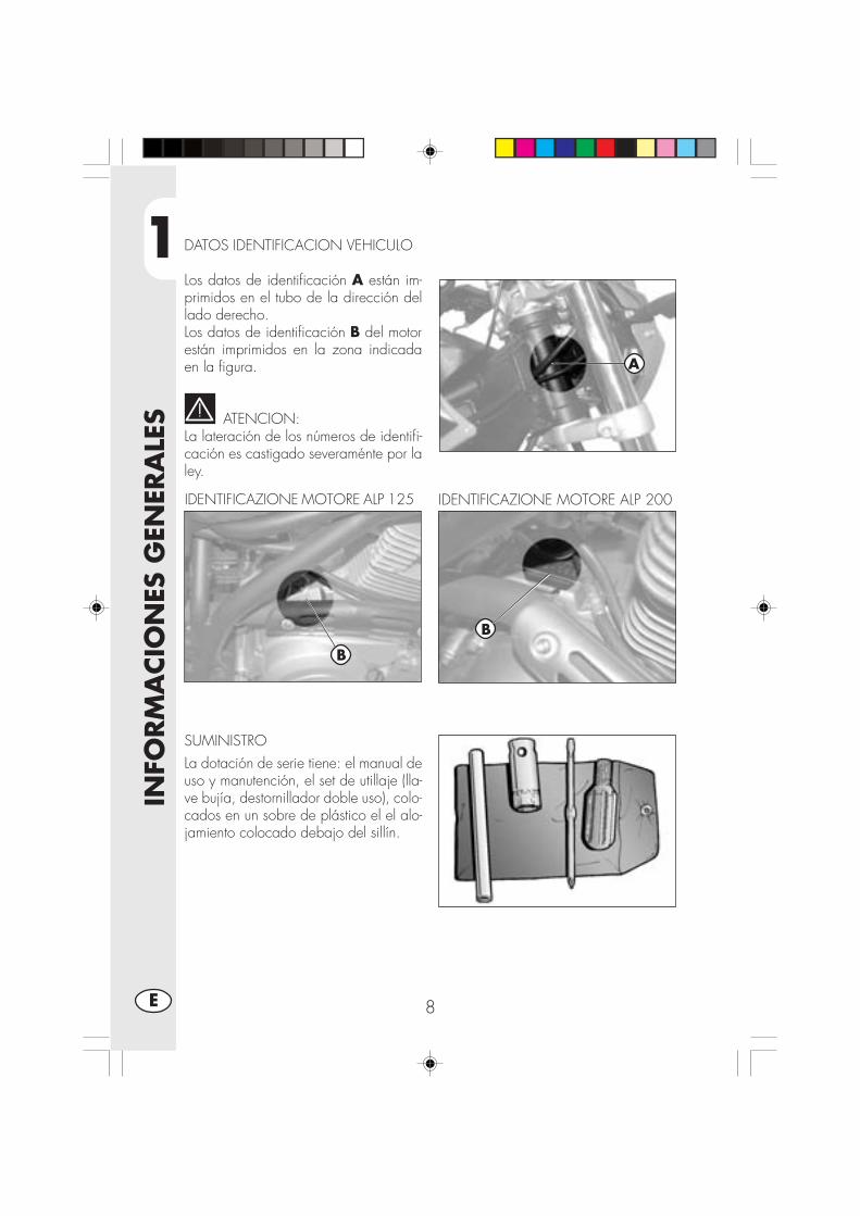
1
INFO
RM
ACIO
NES
GEN
ERA
LES
8E
DATOS IDENTIFICACION VEHICULO
Los datos de identificación A están im-primidos en el tubo de la dirección dellado derecho.Los datos de identificación B del motorestán imprimidos en la zona indicadaen la figura.
ATENCION:La lateración de los números de identifi-cación es castigado severaménte por laley.
SUMINISTROLa dotación de serie tiene: el manual deuso y manutención, el set de utillaje (lla-ve bujía, destornillador doble uso), colo-cados en un sobre de plástico el el alo-jamiento colocado debajo del sillín.
IDENTIFICAZIONE MOTORE ALP 125 IDENTIFICAZIONE MOTORE ALP 200
B
B
A

1
INFO
RM
ACIO
NES
GEN
ERA
LES
9 E
CARGA
•Carga max. (conductor + pasajero): 280 Kgs.•No transportar absolutaménte objetos de mucho volumen o muy pesados quepodrían perjudicar la estabilidad del vehículo.
•No transportar objetos que sobresalgan del vehículo o que cubran los dispositivosde iluminación y de señalización.
ATENCION:Para tener una conducción segura controlar con frecuencia los neumáticos.•Tener la presión de los neumáticos dentro de los limites indicados.•Efectuar el control de la presión cada 15 dias.•Verificar la presión solo con los neumáticos fríos.•Controlar antes de cada viaje que los neumáticos no tengan cortes, rajaduras,abrasiones, hinchazones, etc…. En tal caso hecer examinar el neumático por unexperto puesto que se podrían verificar condiciones extremamente peligrosas.
•En el caso de pinchazo parar inmediatamente el vehículo; seguir viajando, además deser riesgoso, puede provocar irremediables daños al neumático y a la llanta.
•El espesor mínimo de la banda de rodadura de los neumáticos (TUBE TYPE) no debe sernunca inferior a los 2 mm. La falta de respeto de esta norma es castigada por la ley.
•El espesor mínimo de la banda de rodadura de los neumáticos (TUBE TYPE) no debe sernunca inferior a los 2 mm. La falta de respeto de esta norma es castigada por la ley.
NEUMATICOS
Neumatico Delantero Trasero Dimensiones 80/100 - 19 49P 120/90-16 63P Presión 1,4 ÷1,5 bar 1,5 ÷1,6 bar
Presión muy baja Presión muy altaPresión correcta

1
INFO
RM
ACIO
NES
GEN
ERA
LES
10E
CONOCIMIENTO DEL VEHICULO
1
2
34
5
7
8
9
19
20
13
14
10
15
16
12
17
11
11
18
21
22
24
25
24
17
6
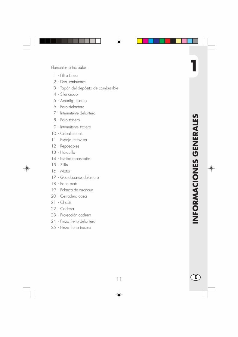
1
INFO
RM
ACIO
NES
GEN
ERA
LES
11 E
Elementos principales:
1 - Filtro Linea2 - Dep. carburante3 - Tapón del depósito de combustible4 - Silenciador5 - Amortig. trasero6 - Faro delantero7 - Intermitente delantero
8 - Faro trasero
9 - Intermitente trasero
10 - Caballete lat.11 - Espejo retrovisor12 - Reposapies13 - Horquilla14 - Estribo reposapiés15 - Sillín16 - Motor17 - Guardabarros delantero18 - Porta matr.19 - Palanca de arranque20 - Cerradura casci21 - Chasis22 - Cadena23 - Protección cadena24 - Pinza freno delantero25 - Pinza freno trasero

1
INFO
RM
ACIO
NES
GEN
ERA
LES
12E
LLAVESEl vehículo se suministra con dos llavesque se utilizan para el conmutador/blo-queo del manillar y para la cerraduradel casco.
ATENCION:No conservar la llave de repuesto en elinterior del vehículo, sino en un lugarseguro y a su alcance. Aconsejamosanotar en este manual (o en otro lugar)el número de código imprimido en lasllaves. En el caso que se pierdan las dos,se podran pedir duplicados.
CONMUTADOR / BLOQUEO DIREC-CIONControlar el circuito de encendido, elfuncionamiento del bloquéo de la direc-ción y la abertura del sillín.
OFF: Sistema eléctrico desconectado.ON: Se puede efectuar el encendido
del vehículo.LOCK: Introducción del bloquéo de la
dirección.Para realizar esta operación esnecesario girar el manillar haciala izquierda, empujar la llavegirarla completamente en senti-do contrario a las agujas del re-loj y luago soltarla.
CERRADURA CASCOIntroducir la llave en la cerradura colo-cada en el lado izquierdo del sillín y gi-rarla en sentido contrario a las agujasdel reloj para abrir el gancho portacasco.
ONOFF
LOCK

1
INFO
RM
ACIO
NES
GEN
ERA
LES
13 E
TABLERO Y MANDOS
Nota: el encendido del testigo del caballete indica que el mismo caballete estábajado. Por razones de seguridad el motor se apaga en el momento de la introduc-ción de una marcha.
2
10
11
8
1
9
6
3
5
4
7
12
13
14
15
16
17
1- LCD2- Conmutador de llave3- Testigo punto neutro4- Testigo intermitentes5- Testigo luces de carretera6- Testigo caballete7- Pulsador SCROLL8- Palanca embrague9- Palanca Starter (sólo en Urban125)
10- Palanca del freno delantero11 - Puño acelerador12 - Pulsador de encendido13 - Pulsador stop motor14 - Pulsador Intermitentes15 - Pulsador claxon16 - Conmutador de luces17 - Passing
1
INFO
RM
ACIO
NES
GEN
ERA
LES
14E
INSTRUCCIONES PARA LA CONFIGURACIÓN Y EL FUNCIONAMIEN-TO DEL CUENTAKILÓMETROS
ÍNDICE DE LOS ARGUMENTOS
APARTADO CONTENIDO
10.0 Test inicial y página vídeo principal
10.1 Indicación testigos luminosos
10.2 Velocidad instantánea y kilómetros totales recorridos (ODO)
20.0 Funciones secundarias
20.1 Totalizador parcial (TRP)
20.2 Reloj (CLK)
20.3 Cronómetro (LAP)
20.4 Velocidad máxima alcanzada (MÁX)
30.0 Inactividad prolongada
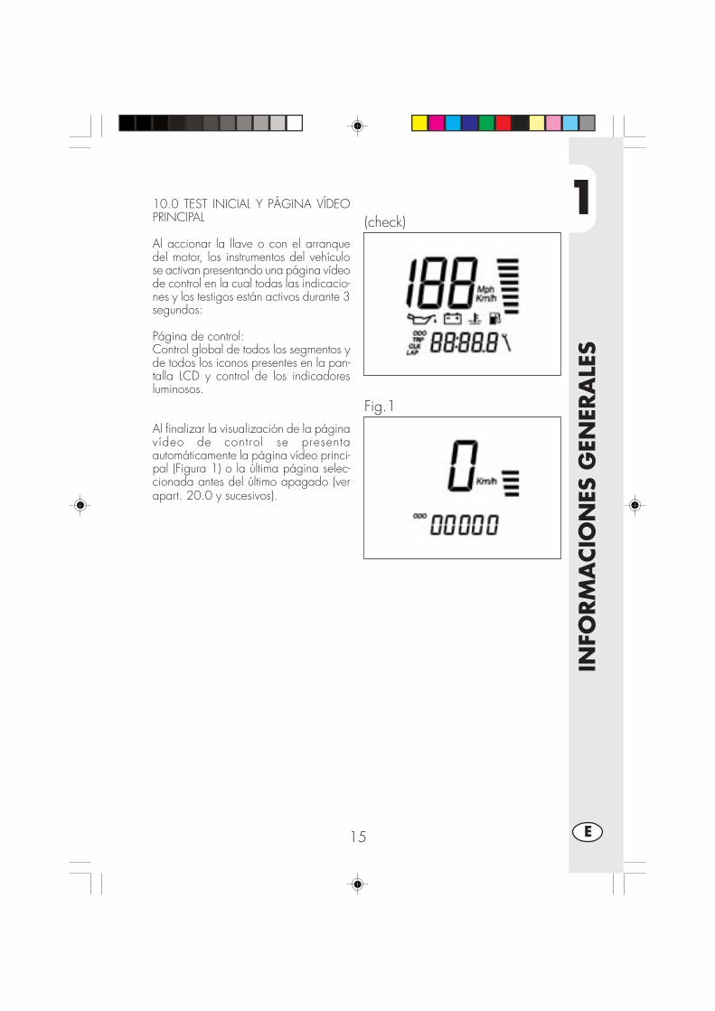
1
INFO
RM
ACIO
NES
GEN
ERA
LES
15 E
10.0 TEST INICIAL Y PÁGINA VÍDEOPRINCIPAL
Al accionar la llave o con el arranquedel motor, los instrumentos del vehículose activan presentando una página vídeode control en la cual todas las indicacio-nes y los testigos están activos durante 3segundos:
Página de control:Control global de todos los segmentos yde todos los iconos presentes en la pan-talla LCD y control de los indicadoresluminosos.
Al finalizar la visualización de la páginavídeo de control se presentaautomáticamente la página vídeo princi-pal (Figura 1) o la última página selec-cionada antes del último apagado (verapart. 20.0 y sucesivos).
(check)
Fig.1

1
INFO
RM
ACIO
NES
GEN
ERA
LES
16E
10.1 Indicación testigos luminosos ypulsador scroll
El instrumento cuenta con 4 testigosluminosos con funciones deseñalización y aviso:
•Testigo Caballete, rojo A: cuandoestá activo indica que el caballetelateral del vehículo está bajo.
•Testigo Neutral, verde B: cuando estáactivo indica que el cambio está enpunto muerto.
•Testigo Luz de carretera, azul C:cuando está activo indica que el farode luz de carretera está encendido.
•Testigo Intermitentes, verde D: cuandoestá activo indica que los intermitentes(derechos o izquierdos) están activos.
•Pulsador Scroll E, permite desplazarsedentro del instrumento seleccionando lafunción deseada (Ver apartado 20.0 ysucesivos)
A
B
C
DE
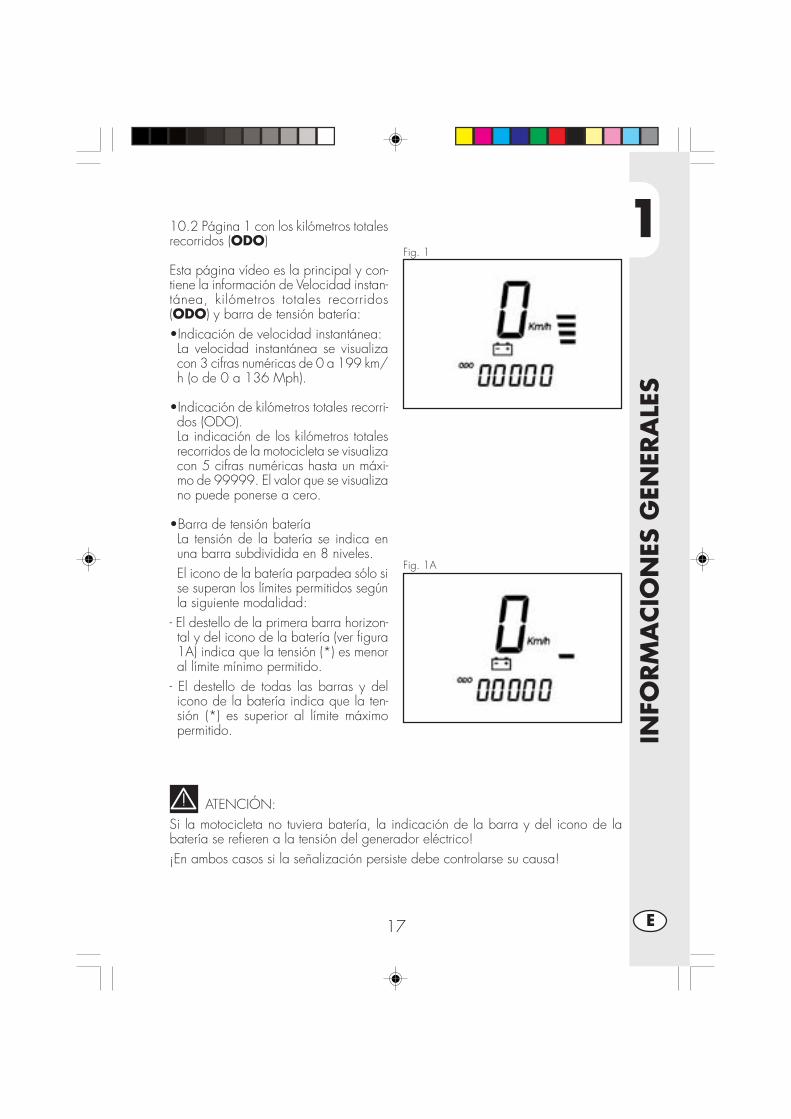
1
INFO
RM
ACIO
NES
GEN
ERA
LES
17 E
Fig. 1
Fig. 1A
10.2 Página 1 con los kilómetros totalesrecorridos (ODO)
Esta página vídeo es la principal y con-tiene la información de Velocidad instan-tánea, kilómetros totales recorridos(ODO) y barra de tensión batería:•Indicación de velocidad instantánea:La velocidad instantánea se visualizacon 3 cifras numéricas de 0 a 199 km/h (o de 0 a 136 Mph).
•Indicación de kilómetros totales recorri-dos (ODO).La indicación de los kilómetros totalesrecorridos de la motocicleta se visualizacon 5 cifras numéricas hasta un máxi-mo de 99999. El valor que se visualizano puede ponerse a cero.
•Barra de tensión bateríaLa tensión de la batería se indica enuna barra subdividida en 8 niveles.El icono de la batería parpadea sólo sise superan los límites permitidos segúnla siguiente modalidad:
- El destello de la primera barra horizon-tal y del icono de la batería (ver figura1A) indica que la tensión (*) es menoral límite mínimo permitido.
- El destello de todas las barras y delicono de la batería indica que la ten-sión (*) es superior al límite máximopermitido.
ATENCIÓN:Si la motocicleta no tuviera batería, la indicación de la barra y del icono de labatería se refieren a la tensión del generador eléctrico!¡En ambos casos si la señalización persiste debe controlarse su causa!

1
INFO
RM
ACIO
NES
GEN
ERA
LES
18E
20.0 FUNCIONES SECUNDARIASDesde la página vídeo principal, se puede acceder en secuencia a las funcionessecundarias sucesivas que permiten visualizar la información según la siguientelista:
Totalizador parcial (TRP)Reloj (CLK)Cronómetro (LAP)Velocidad máxima (MÁX)
En todos los casos, además de la información pertinente a la página vídeo especí-fica, continuarán visualizándose en la pantalla la indicación de velocidad instantá-nea y la barra/icono de la tensión batería.
Se acceden a todas las páginas vídeo, comenzando por la principal (ODO), sóloen su secuencia, mediante un breve accionamiento del pulsador SCROLL. Estosignifica que el orden de visualización será el siguiente:
ODO -> TRP -> CLK -> LAP -> MÁX
Naturalmente, si se presiona el pulsador SCROLL cuando se visualiza la páginavídeo de la Velocidad máxima (MÁX), se pasará nuevamente a la página princi-pal (ODO) y se podrá reanudar la secuencia según como se desee.
ATENCIÓN:NO SE PERMITE EL USO DEL PULSADOR SCROLL DURANTE LA MARCHA DELVEHÍCULO, ES DECIR CUANDO LA INDICACIÓN DE LA VELOCIDAD INSTANTÁ-NEA ES DIFERENTE DE 0 Km/h-Mph.ESTA MEDIDA GARANTIZA LA SEGURIDAD REQUERIDA DURANTE LA CONDUC-CIÓN DE LA MOTOCICLETA.

1
INFO
RM
ACIO
NES
GEN
ERA
LES
19 E
Fig.2
20.1 Totalizador parcial (TRP)
Desde la figura 1, con el vehículo dete-nido, presionando brevemente el pulsa-dor SCROLL se pasa a la figura 2 quecontiene la información de Velocidadinstantánea, kilómetros parciales recorri-dos (TRP) y barra de tensión de la bate-ría:•Km/h (Mph) indicado en 3 cifras (gran-des).
•Totalizador parcial TRP en 4 cifras (pe-queñas)
•Barra de tensión de la bateríaEl totalizador parcial utiliza 4 cifras enformato 000,0 y permite medir la dis-tancia parcial en valores que van de0,0Km/Millas a 999,9 Km/Millas. Alllegar a 999,9 y al recorrer el siguiente0,1Km o Milla la indicación se restable-ce en 0,0.La puesta a cero manual puede realizar-se (con figura 2 activa) con el vehículodetenido manteniendo presionado elpulsador SCROLL durante aproximada-mente 3 segundos hasta que se visualicela indicación “—.-“ en las 4 cifras pe-queñas.

1
INFO
RM
ACIO
NES
GEN
ERA
LES
20E
Fig. 3
20.2 RELOJ CLK
Desde la figura 2, con el vehículo dete-nido y presionando brevemente el pulsa-dor SCROLL se pasa a la figura 3 quecontiene la información de Velocidadinstantánea, reloj 24h y barra de ten-sión de la batería:•Km/h indicado en 3 cifras (grandes).•Reloj hh:mm en 4 cifras (pequeñas)•Barra de tensión de la bateríaEl reloj indica la hora en un arco de 24horas (de 0h:00’ a 23h:59’) y se lo pue-de regular sólo con el vehículo detenidomediante el siguiente procedimiento:•Presionar el pulsador SCROLL hastaque destellen los números correspon-dientes a las horas.
•Soltando y presionando nuevamente elpulsador SCROLL, las horas avanzande un número. Manteniéndolo presio-nado avanzan automáticamente. Deján-dolo inactivo se pasa al punto 4.
•Soltar el pulsador SCROLL cuando fi-naliza la configuración de las horas:después de 2 segundos comienzan aparpadear las cifras de los minutos.
•Seguir el mismo procedimiento indica-do en el punto 2 para configurar losminutos. Dejando inactivo el pulsadorSCROLL durante 2 segundos, tambiénse memorizan los minutos y se sale dela modalidad de regulación del reloj.

1
INFO
RM
ACIO
NES
GEN
ERA
LES
21 E
Fig. 4
20.3 CRONÓMETRO LAP
Desde la figura 3, con el vehículo dete-nido, presionando brevemente el pulsa-dor se pasa a la figura 4 que contienela información de Velocidad instantánea,cronómetro minutos:segundos y barra detensión de la batería:•Km/h indicado en 3 cifras (grandes).•Cronómetro mm:ss en 4 cifras (peque-ñas)•Barra de tensión de la bateríaCuando la página vídeo se visualizacomo en la figura 4 significa que parapoder utilizar la función cronómetro, lamisma debe estar activada. El procedi-miento de activación consiste en presio-nar y mantener presionado el pulsadorSCROLL durante más de 1 segundohasta que desaparezca la indicación “—:—“ y se visualice el cronómetro en laforma de MINUTOS:SEGUNDOS comose describe en la figura 4A”
Fig. 4A
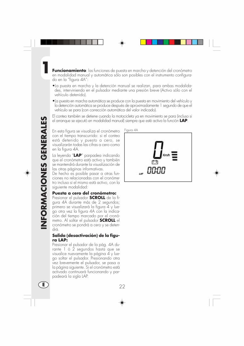
1
INFO
RM
ACIO
NES
GEN
ERA
LES
22E
Funcionamiento: las funciones de puesta en marcha y detención del cronómetroen modalidad manual y automática sólo son posibles con el instrumento configura-do en la “figura 4A”:•La puesta en marcha y la detención manual se realizan, para ambas modalida-des, interviniendo en el pulsador mediante una presión breve (Activo sólo con elvehículo detenido).
•La puesta en marcha automática se produce con la puesta en movimiento del vehículo yla detención automática se produce después de aproximadamente 1 segundo de que elvehículo se para (con corrección automática del valor indicado).
El conteo también se detiene cuando la motocicleta ya en movimiento se para (incluso siel arranque se ejecutó en modalidad manual) siempre que esté activa la función LAP.
Figura 4AEn esta figura se visualiza el cronómetrocon el tiempo transcurrido: si el conteoestá detenido y puesto a cero, sevisualizarán todas las cifras a cero comoen la figura 4A.La leyenda “LAP” parpadea indicandoque el cronómetro está activo y tambiénse mantendrá durante la visualización delas otras páginas informativas.De hecho es posible pasar a otras fun-ciones no relacionadas con el cronóme-tro incluso si el mismo está activo, con lasiguiente modalidad:Puesta a cero del cronómetro:Presionar el pulsador SCROLL de la fi-gura 4A durante más de 2 segundos;primero se visualizará la figura 4 y lue-go otra vez la figura 4A con la indica-ción del tiempo marcado por el cronó-metro. Al soltar el pulsador SCROLL elcronómetro se pondrá a cero y se deten-drá.Salida (desactivación) de la figu-ra LAP:Presionar el pulsador de la pág. 4A du-rante 1 ó 2 segundos hasta que sevisualice nuevamente la página 4 y lue-go soltar el pulsador. Presionando otravez brevemente el pulsador, se pasa ala página siguiente. Si el cronómetro estáactivado continuará funcionando y par-padeará la sigla LAP.

1
INFO
RM
ACIO
NES
GEN
ERA
LES
23 E
Figura 5
20.4 VELOCIDAD MÁXIMA ALCANZA-DA MÁXDesde la figura 4, con el vehículo dete-nido, presionando brevemente el pulsa-dor SCROLL se pasa a la figura 5 quecontiene la información de Velocidadinstantánea, velocidad máxima alcanza-da y barra de tensión de la batería:•Km/h indicado en 3 cifras (grandes).•Velocidad máxima alcanzada en 3 ci-fras (pequeñas)
•Barra de tensión de la bateríaLa indicación “Km/h” o “Mph” parpa-dea en esta página vídeo.Durante la marcha del vehículo, la indi-cación de velocidad máxima alcanza-da se actualiza permanentemente y seindica en las 3 cifras pequeñas. En to-dos los casos se memoriza este valor in-cluso si la figura 5 no está activa.La puesta a cero de la indicación puederealizarse (con figura 5 activa) con elvehículo parado, manteniendo presiona-do el pulsador SCROLL durante aproxi-madamente 3 segundos hasta que sevisualice la indicación “—.-“ en las 3cifras pequeñas.Para regresar a la figura 1 inicial, sedebe accionar brevemente el pulsadorSCROLL.
30.0 Inactividad prolongadaEl instrumento digital se alimenta con labatería del vehículo, en caso de inactivi-dad prolongada es aconsejabledesconectarla.Sin embargo dicha operación elimina lasconfiguraciones de la hora y la veloci-dad máxima alcanzada.

1
INFO
RM
ACIO
NES
GEN
ERA
LES
24E
DATOS TECNICOS
CARGA MAXIMA
Conductor + pasajero.................................................................. 280 (kgs)
PESO DEL VEHICULO
Peso total en vacío URBAN 200.................................................... 103 (kgs)
Peso total en vacío URBAN 125.................................................... 101 (kgs)
DIMENSIONES
Longitud total ............................................................................. 2143 mm
Anchura total ............................................................................... 820 mm
Altura total ................................................................................ 1170 mm
Distancia entre ejes .................................................................... 1372 mm
Altura sillín .................................................................................. 836 mm
Distancia al terreno ...................................................................... 288 mm
BASTIDOR.................. ................................ de acero de doble cuna cerrada
CAPACIDAD DE LLENADO
Tanque combustible ........................................................................... 6 (lts)
De los cuales lts. De reserva ............................................................. 1,5 (lts)
Consumo promedio ....................................................................25 kms/lt.

1
INFO
RM
ACIO
NES
GEN
ERA
LES
25 E
SUSPENSION DELANTERA
Horquilla hidráulica con barras de Ø 37 mm.
Cantidad de aceite por vástago:
Derecho ................................................................................. 310 ± 5 cc
Izquierdo ................................................................................ 310 ± 5 cc
Tipo de aceite ...................................................................... SHELL EBH16
Nivel del aceite...................................142 mm del borde superior del tubo dela horquilla a final de carrera y sin muelle.
Antecarrera ................................................................................ 82,5 mm
SUSPENSION TRASERA
Monoamortiguador hidráulico progresivo y regulación en extención y precarga delmuelle.
Carrera amortiguador ..................................................................... 63 mm
FRENO DELANTERO
De disco Ø 245 mm con mando hidráulico
FRENO TRASERO
De disco Ø 220 mm con mando hidráulico

1
INFO
RM
ACIO
NES
GEN
ERA
LES
26E
MOTOR URBAN 125
Tipo .................... Monocilíndrico, inclinado hacia adelante, 4 tiempos, SOHC
Diámetro X carrera .................................................................... 54x54 mm
Cilindrada (cm3) .......................................................................... 124 cm3
Relación de compresión ..................................................................... 10:1
Carburador ...................................................... MIKUNI UCAL 5Nh Ø26-38
Lubricación ............................................................... con aceite en el carter
Alimentación ......... a de gasolina (con número de octanos mínimo 95 sin plomo)
Refrigeración .................................................................. circulación de aire
Bujía.............................................................................. NGK R CR7 HSA
Embrague ..................................................... multidisco empapado en aceite
Cambio .............................................................................. 5 velocidades
Relación reducción primaria ............................................................. 68/20
Relación reducción final ................................................................. 60/14
Relación cambio 1° ....................................................................... 37/14
2° ....................................................................... 32/18
3° ....................................................................... 25/19
4° ....................................................................... 23/22
5° ....................................................................... 21/24
Cadena de transmisión ......................................... REGINA 1/2, 5/16 P. 136
Juego válvulas ................... admisión mm 0,08 - 0,12 escape mm 0,10 - 0,14
Arranque ................................................................ eléctrico y/o kick-starter
Aceite motor ......................................................... BARDAHL XTM 15W 50
Cantidad aceite en el motor, ........................................ 1,000 ml / 1,050 ml

1
INFO
RM
ACIO
NES
GEN
ERA
LES
27 E
MOTOR URBAN 200
Tipo ..................................... monocilíndrico de cuatro tiempos SUZUKI H402
Diámetro X carrera ................................................................. 66x58,2 mm
Cilindrada (cm3) .......................................................................... 199 cm3
Relación de compresión .................................................................... 9,4:1
Carburador ............................................................... MIKUNI BST31 42AD
Lubricación ............................................................... con aceite en el carter
Alimentación ......... a de gasolina (con número de octanos mínimo 95 sin plomo)
Refrigeración .................................................................. circulación de aire
Bujía................................................................................... NGK DR8 EA
Embrague ..................................................... multidisco empapado en aceite
Cambio .............................................................................. 5 velocidades
Relación reducción primaria ................................................. 3,157 (60/19)
Relación reducción final ..................................................... 3,200 (48/15)
Relación cambio 1° ........................................................... 3,000 (33/11)
2° ........................................................... 1,933 (29/15)
3° ........................................................... 1,437 (23/16)
4° ........................................................... 1,095 (23/21)
5° ........................................................... 0,913 (21/23)
Cadena de transmisión ......................................... REGINA 5/8, 1/4, P.104
Juego válvulas .........................................admisión y escape mm 0,08 - 0,13
Arranque ................................................................ eléctrico y/o kick-starter
Aceite motor ......................................................... BARDAHL XTM 15W 50
Cantidad aceite en el motor, . cambio de aceite 850 ml con cambio filtro 950 mlrevisión 1300 ml

1
INFO
RM
ACIO
NES
GEN
ERA
LES
28E
ESQUEMA ELÉCTRICO URBAN 125

1
INFO
RM
ACIO
NES
GEN
ERA
LES
29 E
Colores:Bi = BlancoVe = VerdeMa= MarrónVi = Violeta
Bl = AzulNe = NegroGi = AmarilloRs = Rojo
Ar = NaranjaAz = CelesteRo = RosaGr = Gris
ESQUEMA ELÉCTRICO URBAN 1251) INTERMITENTE DEL. D. (BOMBILLA 12V-10W)2) INTERRUPTOR DELANTERO3) CONMUTADOR DERECH.4) PULSADOR PARADA MOTOR5) BOTÓN ARRANQUE6) TESTIGOS CABALLETE7) INDICADOR DE PUNTO MUERTO8) TESTIGO LUZ DE CARRETERA9) INDICADOR LUCES INTERMITENTES10) DISPLAY11) SENSOR12) FARO DELANTERO (12V-5560W)13) LUCE DE POSICIÓN 12V-5W14) PULSADOR CLAXON15) PULSADOR FLASH16) CONMUTADOR LUCES17) CONMUTADOR INTERMITENTES18) CONMUTADOR IZQ.19) INTERRUPTOR EMBRAGUE20) BOBINA A.T.21) DISP. INTERMITENTES22) INTERMITENTE DEL. I. (BOMBILLA 12V-10W)23) REGULADOR 12V24) CONDENSADOR25) MOTOR DE ARRANQUE26) MASA27) DIODOS 1A28) FUSIBLE 15A29) TELERRUPTOR DE ARRANQUE30) BATERIA HERMETICA 12V-9Ah31) INTERMITENTE TRAS. I (BOMBILLA 12V-10W)32) ILUMNACIÓN PLACA (LAMPADA 12V-5W)33) MASA34) POSICIÓN35) STOP36) DIODI 1A37) FARO TRASERO COMPL. (LED)38) INTERMITENTE TRAS. D (BOMBILLA 12V-10W)39) INTERRUPTOR DELANTERO40) SENSOR41) SENSOR P.T.C.42) SENSOR43) MASA44) CONTACTO, INTERRUPTOR PUNTO MUERTO45) DIODO 1A46) PICK-UP47) CENTRALITA ELECTRÓNICA48) CONMUTADOR DE LLAVE49) CLAXON
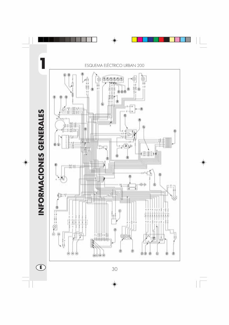
1
INFO
RM
ACIO
NES
GEN
ERA
LES
30E
ESQUEMA ELÉCTRICO URBAN 200
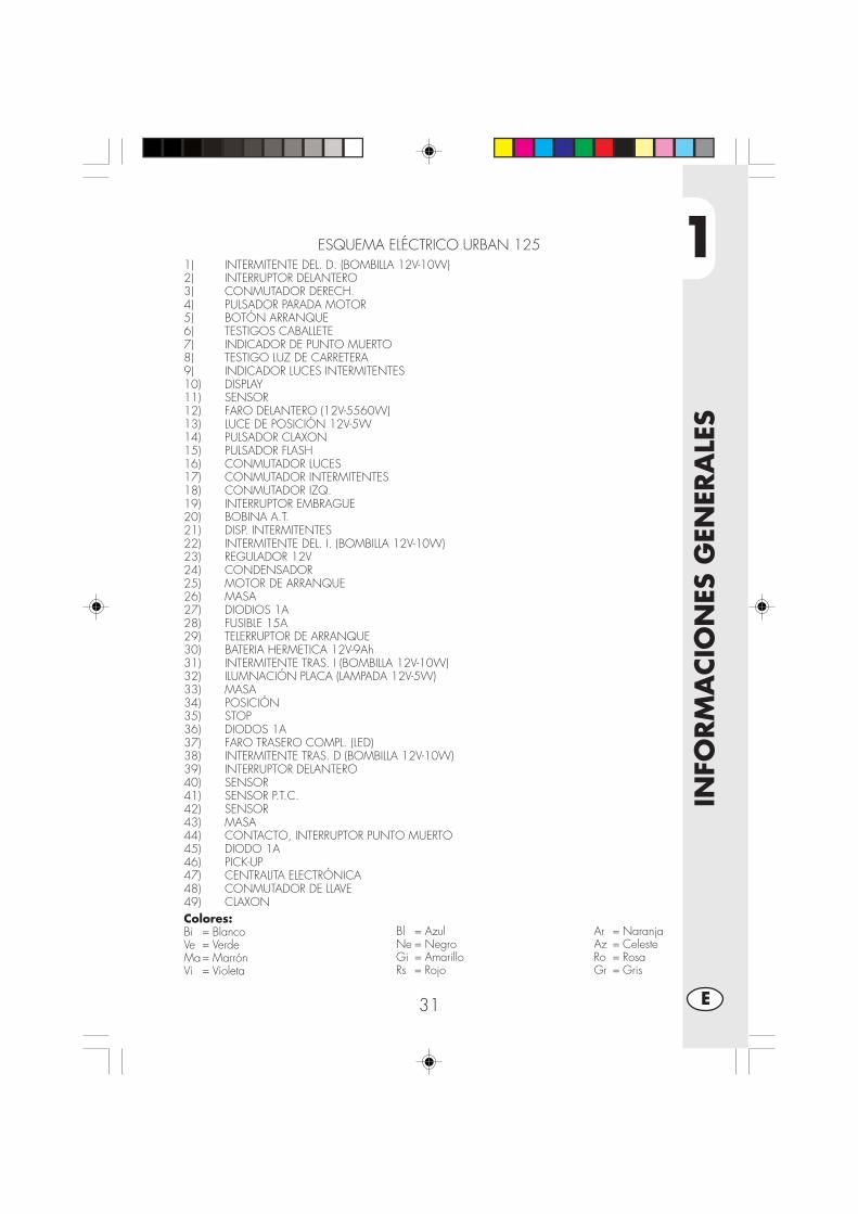
1
INFO
RM
ACIO
NES
GEN
ERA
LES
31 E
Colores:Bi = BlancoVe = VerdeMa= MarrónVi = Violeta
Bl = AzulNe = NegroGi = AmarilloRs = Rojo
Ar = NaranjaAz = CelesteRo = RosaGr = Gris
ESQUEMA ELÉCTRICO URBAN 1251) INTERMITENTE DEL. D. (BOMBILLA 12V-10W)2) INTERRUPTOR DELANTERO3) CONMUTADOR DERECH.4) PULSADOR PARADA MOTOR5) BOTÓN ARRANQUE6) TESTIGOS CABALLETE7) INDICADOR DE PUNTO MUERTO8) TESTIGO LUZ DE CARRETERA9) INDICADOR LUCES INTERMITENTES10) DISPLAY11) SENSOR12) FARO DELANTERO (12V-5560W)13) LUCE DE POSICIÓN 12V-5W14) PULSADOR CLAXON15) PULSADOR FLASH16) CONMUTADOR LUCES17) CONMUTADOR INTERMITENTES18) CONMUTADOR IZQ.19) INTERRUPTOR EMBRAGUE20) BOBINA A.T.21) DISP. INTERMITENTES22) INTERMITENTE DEL. I. (BOMBILLA 12V-10W)23) REGULADOR 12V24) CONDENSADOR25) MOTOR DE ARRANQUE26) MASA27) DIODIOS 1A28) FUSIBLE 15A29) TELERRUPTOR DE ARRANQUE30) BATERIA HERMETICA 12V-9Ah31) INTERMITENTE TRAS. I (BOMBILLA 12V-10W)32) ILUMNACIÓN PLACA (LAMPADA 12V-5W)33) MASA34) POSICIÓN35) STOP36) DIODOS 1A37) FARO TRASERO COMPL. (LED)38) INTERMITENTE TRAS. D (BOMBILLA 12V-10W)39) INTERRUPTOR DELANTERO40) SENSOR41) SENSOR P.T.C.42) SENSOR43) MASA44) CONTACTO, INTERRUPTOR PUNTO MUERTO45) DIODO 1A46) PICK-UP47) CENTRALITA ELECTRÓNICA48) CONMUTADOR DE LLAVE49) CLAXON

1
INFO
RM
ACIO
NES
GEN
ERA
LES
32E
AD
F
B C
DISPOSITIVOS ELECTRICOS
BATERÍASe accede a la batería A retirando elsillín, como se describe en la sección“Desmontaje de la carrocería” de pági-na 52.Desmontar la tapa B desenroscando eltornillo C, desenganchar el elástico D,desconectar los cables y quitarla batería.
ATENCIÓN:Para evitar daños a la instalación
eléctrica, no desconectar nunca los ca-bles con el motor en marcha.Colocar nuevamente la batería (A) en sualojamiento debajo de asiento y fijarlacon el elástico (B).Conectar el terminal de los cables decolor negro en el negativo (-) y los doscables rojos en el positivo (+) y luegocolocar la protección (ver el dibujo).
CENTRALITALa centralita E se encuentra en el ladoizquierdo del vehículo; para acceder aeste dispositivo se debe desmontar elcarenado izquierdo, debajo del depósi-to, como se describe en la página 53.
CLAXONEn la parte delantera sobre el lado iz-quierdo de la motocicleta se encuentrael Claxon F.
E
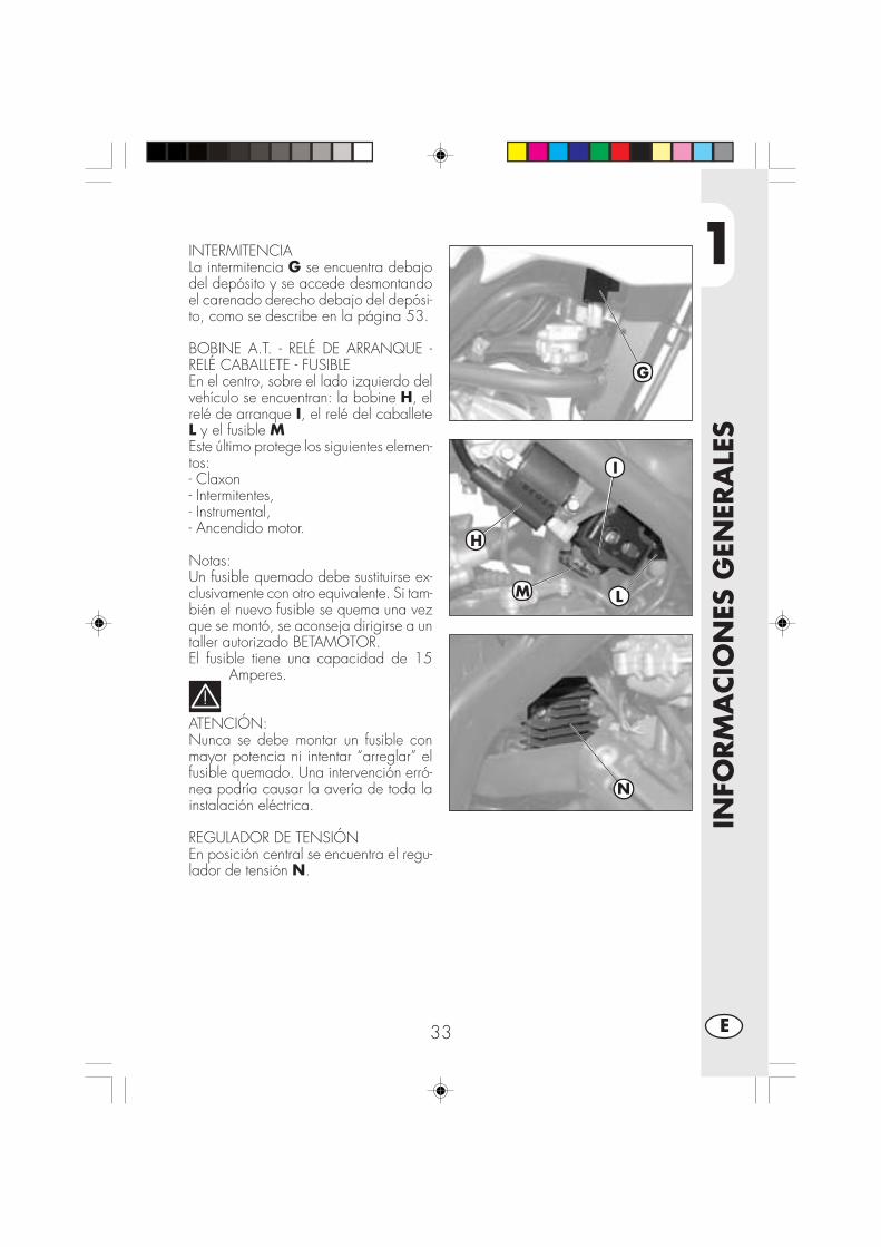
1
INFO
RM
ACIO
NES
GEN
ERA
LES
33 E
INTERMITENCIALa intermitencia G se encuentra debajodel depósito y se accede desmontandoel carenado derecho debajo del depósi-to, como se describe en la página 53.
BOBINE A.T. - RELÉ DE ARRANQUE -RELÉ CABALLETE - FUSIBLEEn el centro, sobre el lado izquierdo delvehículo se encuentran: la bobine H, elrelé de arranque I, el relé del caballeteL y el fusible MEste último protege los siguientes elemen-tos:- Claxon- Intermitentes,- Instrumental,- Ancendido motor.
Notas:Un fusible quemado debe sustituirse ex-clusivamente con otro equivalente. Si tam-bién el nuevo fusible se quema una vezque se montó, se aconseja dirigirse a untaller autorizado BETAMOTOR.El fusible tiene una capacidad de 15
Amperes.
ATENCIÓN:Nunca se debe montar un fusible conmayor potencia ni intentar “arreglar” elfusible quemado. Una intervención erró-nea podría causar la avería de toda lainstalación eléctrica.
REGULADOR DE TENSIÓNEn posición central se encuentra el regu-lador de tensión N.
H
L
N
I
M
G

1
INFO
RM
ACIO
NES
GEN
ERA
LES
34E
VÁLVULA AIS
Se llama AIS y es un sistema de admi-sión de aire que permite completar lacombustión de la parte de hidrocarbu-ros residuos del ciclo termodinámico queno han participado en la combustión.Para acceder a la válvula A se debedesmontar la protección derecha deba-jo del depósito, como se describe en lapágina 52
A

2
UTI
LIZ
ACIO
N D
EL V
EHIC
ULO
35 E
INDICE ARGUMENTOS
CAP. 2 UTILIZACION DEL VEHICULO
Controles y manutención antes y después de la utilización en todo terreno
Lubricantes y líquidos aconsejados.
Rodaje.
Arranque del motor.
Parada del motor.
Abastecimiento combustible
2
UTI
LIZ
ACIO
N D
EL V
EHIC
ULO
36E
COMPROBACIONES Y MANUTENCION ANTES Y DESPUES DE LA UTILIZACIONEN TODO TERRENO
Para evitar desagradables inconvenientes durante el funcionamiento del vehículo seaconseja efectuar, sea antes que después del uso, algunas operaciones de controly manutención. En efecto, pocos minutos dedicados a ésta operación, además deobtener una conducción mas segura, pueden hacerle ahorrar tiempo y dinero. Porlo tanto proceder de la siguiente manera:
NEUMATICOS verificar la presión, las condiciones generales y el espe-sor de la banda de rodadura (vea pag. 9).
RAYOS verificar el correcto tensionamiento.CONJUNTO DE PERNOS verificar el apriete de todos los pernos.CADENA verificar el tensionamiento (juego 20 mm) y si es nece-
sario engrasar.FILTRO DEL AIRE limpiar el filtro y empaparlo en aceite(vea pag.48).
Nota:Verificar la presencia de los documentos de identificación del vehículo.En los dias frios se aconseja antes de la salida, calentar el motor dejandolo enfunción en ralentí por algunos instantes. Cada vez que utilizamos el vehículo entodo terreno es necesario lavarlo con muy bien.
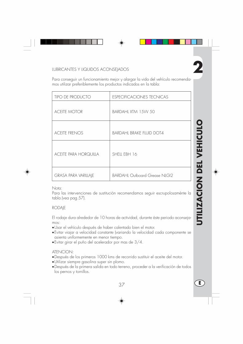
2
UTI
LIZ
ACIO
N D
EL V
EHIC
ULO
37 E
TIPO DE PRODUCTO ESPECIFICACIONES TECNICAS
ACEITE MOTOR BARDAHL XTM 15W 50
ACEITE FRENOS BARDAHL BRAKE FLUID DOT4
ACEITE PARA HORQUILLA SHELL EBH 16
GRASA PARA VARILLAJE BARDAHL Outboard Grease NLGI2
LUBRICANTES Y LIQUIDOS ACONSEJADOS
Para conseguir un funcionamiento mejor y alargar la vida del vehículo recomenda-mos utilizar preferiblemente los productos indicados en la tabla:
Nota:Para las intervenciones de sustitución recomendamos seguir escrupolosaménte latabla.(vea pag.57).
RODAJE
El rodaje dura alrededor de 10 horas de actividad, durante éste periodo aconseja-mos:•Usar el vehículo después de haber calentado bien el motor.•Evitar viajar a velocidad constante (variando la velocidad cada componente seasienta uniformemente en menor tiempo.
•Evitar girar el puño del acelerador por mas de 3/4.
ATENCION:•Después de los primeros 1000 kms de recorrido sustituir el aceite del motor.•Utilizar siempre gasolina super sin plomo.•Después de la primera salida en todo terreno, proceder a la verificación de todoslos pernos y tornillos.

2
UTI
LIZ
ACIO
N D
EL V
EHIC
ULO
38E
ARRANQUE DEL MOTOR
•Colocar la válvula del depósito decombustible en posición ABIERTA (verel diseño al lado).
•Girar la llave del conmutador en sentidohorario y asegurarse de que el testigode punto muerto, que se encuentra enel salpicadero, esté encendido (ver nota3 en la página 13).
•Asegurarse de que el interruptor deemergencia A, ubicado en el mandodel acelerador, se encuentre en posiciónON.
Nota:Con el motor frío conectar el cebador D.
Arranque eléctricoTirar de la palanca del embrague y almismo tiempo presionar el pulsador dearranque B en el mando del acelerador,sin girar el puño del mando delacelerador.Kick-starterIntervenir en la palanca puesta en marchaC, efectuando con el pie un golpe preci-so y luego replegarla.
Nota:Se puede arrancar el motor con elcaballete bajo y el testigo rojo en elsalpicadero encendido, siempre que elpedal de acople de las marchas esté enpunto muerto, indicado mediante eltestigo verde en el instrumental.Por razones de seguridad, el eventualacople de la marcha, incluso con elembrague activado, produce elapagado del motor.Por lo tanto se debe cerrar el caballete yluego acoplar la marcha.
Nota:En caso de emergencia, éste vehículo pue-de funcionar también sin usar la batería.
A
ON OFF
B
C
Abierto Cerrado Depósito
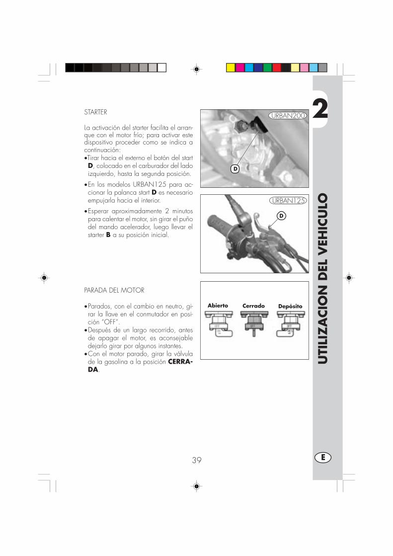
2
UTI
LIZ
ACIO
N D
EL V
EHIC
ULO
39 E
STARTER
La activación del starter facilita el arran-que con el motor frío; para activar estedispositivo proceder como se indica acontinuación:•Tirar hacia el externo el botón del startD, colocado en el carburador del ladoizquierdo, hasta la segunda posición.
•En los modelos URBAN125 para ac-cionar la palanca start D es necesarioempujarla hacia el interior.
•Esperar aproximadamente 2 minutospara calentar el motor, sin girar el puñodel mando acelerador, luego llevar elstarter B a su posición inicial.
PARADA DEL MOTOR
•Parados, con el cambio en neutro, gi-rar la llave en el conmutador en posi-ción “OFF”.
•Después de un largo recorrido, antesde apagar el motor, es aconsejabledejarlo girar por algunos instantes.
•Con el motor parado, girar la válvulade la gasolina a la posición CERRA-DA.
D
D
Abierto Cerrado Depósito
URBAN125
URBAN200
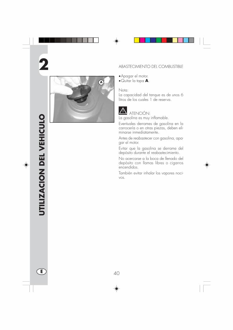
2
UTI
LIZ
ACIO
N D
EL V
EHIC
ULO
40E
ABASTECIMIENTO DEL COMBUSTIBLE
•Apagar el motor.•Quitar la tapa A.
Nota:La capacidad del tanque es de unos 6litros de los cuales 1 de reserva.
ATENCIÓN:La gasolina es muy inflamable.Eventuales derrames de gasolina en lacarrocería o en otras piezas, deben eli-minarse inmediatamente.Antes de reabastecer con gasolina, apa-gar el motor.Evitar que la gasolina se derrame deldepósito durante el reabastecimiento.No acercarse a la boca de llenado deldepósito con llamas libres o cigarrosencendidos.También evitar inhalar los vapores noci-vos.
A

3
CO
NTR
OLE
S Y
MA
NU
TEN
CIO
N
41 E
INDICE DE LOS ARGUMENTOS
CAP. 3 CONTROLES Y MANUTENCION
Aceite y filtro aceite
Tubo recolección humo
Aceite bomba frenos, espurgo frenos
Aceite horquilla
Filtro aire
Bujía
Frenos: delantero, trasero
Batería
Remoción carrocería
Nota para trial
Limpieza del vehículo y comprobaciones
Manutención programada
Larga inactividad del vehículo

3
CO
NTR
OLE
S Y
MA
NU
TEN
CIO
N
42E
ACEITE MOTOR Y FILTRO ACEITEURBAN200
VerificaciónTener el vehículo en posición vertical conrespecto al terreno. Con el motor friocontrolar por medio de la mirilla el niveldel aceite A, el nivel del aceite que nodebe bajar nunca por debajo de la miri-lla. Para restablecer el nivel proceder alllenado a travez de la tapa de carga B.LlenadoEventuales restablecimientos del nivel sedeben efectuar después del control delnivel max. indicado en la mirilla A.SustituciónEfectuar siempre la sustitución del aceitecon el motor caliente, prestando atenciónen no tocar el motor y el mismo aceitepara evitar quemaduras.•El aceite debe sustituirse junto con elfiltro de aceite.
•Colocar la moto sobre el caballete.•Colocar un contenedor debajo delmotor en correspondencia con el tapónde drenaje D.
•Colocar un contenedor debajo delmotor.
•Destornillar el tapón de llenado B y devaciado D.
•Vaciar completamente el carter.•Cerrar el tapón D.•Quitar la tapa del filtro aceite destorni-llando las 3 tuercas de fijación C.
•Quitar el filtro e introducir uno nuevo.• Lubricar con aceite del motor el O-Ringde la tapa del filtro antes del montaje.
•Colocar la tapa del filtro después dehaber montadomuelle y Oring y apre-tar las tres tuercas de fijación.
B
A
C
D
3
CO
NTR
OLE
S Y
MA
NU
TEN
CIO
N
43 E
• Introducir la correcta cantidad de aceite C.•Introducir la cantidad de aceite correcta:- cambio de aceite 850 ml- con cambio de filtro 950 ml- revisión 1.300 ml
•Cerrar nuevamente el tapón de llenadoB.
•Apagar el motor y esperar un minuto.•Apagar el motor y esperar aproximada-mente un minuto, luego controlar el nively llenar si corresponde, nunca superar elnivel máx. indicado en la mirilla A.
Nota:Después de los primeros 1000 kms de re-corrido sustituir el aceite del motor. Las sus-tituciones siguientes deberán realizarse acada 5000 kms15 meses, (ver tabla pag.57) utilizando lubricantes aconsejados enpag. 37.En cambio para el filtro de aceite la pri-mera sustitución se debe realizar junto alaceite motor, las siguientes cada 10.000kms (30 meses).
Advertencia:Eliminar el aceite usado respetando lasnormas vigentes.

3
CO
NTR
OLE
S Y
MA
NU
TEN
CIO
N
44E
ACEITE MOTOR Y FILTRO ACEITEURBAN125VerificaciónTener el vehículo en posición verticalcon respecto al terreno. Con el motorfrio comprobar que haya aceite.LlenadoPara restablecer el nivel añadir aceitea través del orificio del tapón A.SustituciónEfectuar siempre la sustitución del acei-te con el motor caliente, prestando aten-ción en no tocar el motor y el mismoaceite para evitar quemaduras.•Colocar la moto sobre el caballete.•Colocar un contenedor debajo delmotor.
•Destornillar el tapón de llenado A yde vaciado B.
•Vaciar completamente el carter.•Cerrar el tapón B• Introducir 1000 c.c. de aceite.•Cerrar el tapón de llenado A.
ATENCIÓN:El aceite caliente puede provocar gra-ves quemaduras.
Nota:El filtro de aceite rotativo del motorURBAN125 está alojado en el eje delmismo (lado embrague). Recomenda-mos contactar con un concesionarioBetamotor para su sustitución.Nota:Después de los primeros 500 Km derecorrido sustituir el aceite del motor.Para el cambio respetar la tabla en lapágina 57, utilizando los lubricantes re-comendados en la página 37.
Advertencia:Eliminar el aceite usado respetando lasnormas vigentes.
A
B
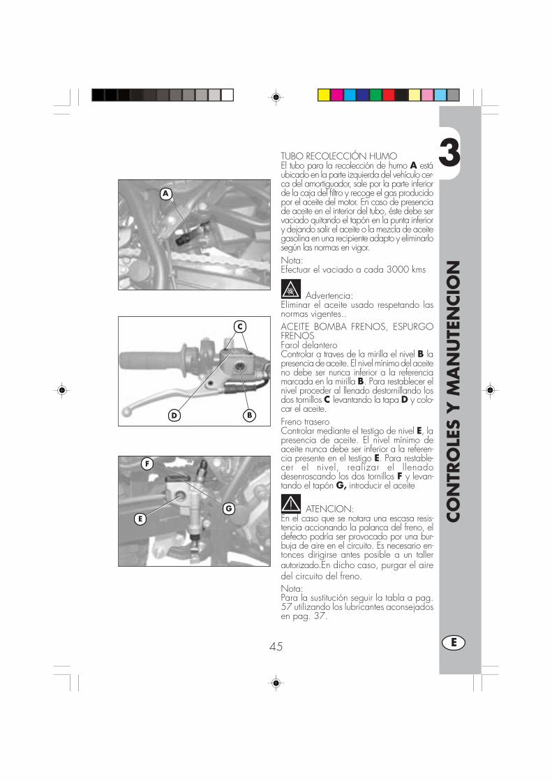
3
CO
NTR
OLE
S Y
MA
NU
TEN
CIO
N
45 E
TUBO RECOLECCIÓN HUMOEl tubo para la recolección de humo A estáubicado en la parte izquierda del vehículo cer-ca del amortiguador, sale por la parte inferiorde la caja del filtro y recoge el gas producidopor el aceite del motor. En caso de presenciade aceite en el interior del tubo, éste debe servaciado quitando el tapón en la punta inferiory dejando salir el aceite o la mezcla de aceitegasolina en una recipiente adapto y eliminarlosegún las normas en vigor.Nota:Efectuar el vaciado a cada 3000 kms
Advertencia:Eliminar el aceite usado respetando lasnormas vigentes..ACEITE BOMBA FRENOS, ESPURGOFRENOSFarol delanteroControlar a traves de la mirilla el nivel B lapresencia de aceite. El nivel mínimo del aceiteno debe ser nunca inferior a la referenciamarcada en la mirilla B. Para restablecer elnivel proceder al llenado destornillando losdos tornillos C levantando la tapa D y colo-car el aceite.Freno traseroControlar mediante el testigo de nivel E, lapresencia de aceite. El nivel mínimo deaceite nunca debe ser inferior a la referen-cia presente en el testigo E. Para restable-cer el nivel, realizar el llenadodesenroscando los dos tornillos F y levan-tando el tapón G, introducir el aceite
ATENCION:En el caso que se notara una escasa resis-tencia accionando la palanca del freno, eldefecto podría ser provocado por una bur-buja de aire en el circuito. Es necesario en-tonces dirigirse antes posible a un tallerautorizado.En dicho caso, purgar el airedel circuito del freno.Nota:Para la sustitución seguir la tabla a pag.57 utilizando los lubricantes aconsejadosen pag. 37.
A
D
C
B
F
EG
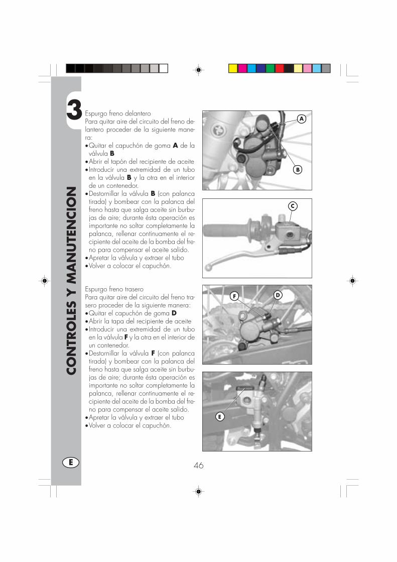
3
CO
NTR
OLE
S Y
MA
NU
TEN
CIO
N
46E
Espurgo freno delanteroPara quitar aire del circuito del freno de-lantero proceder de la siguiente mane-ra:•Quitar el capuchón de goma A de laválvula B
•Abrir el tapón del recipiente de aceite• Introducir una extremidad de un tuboen la válvula B y la otra en el interiorde un contenedor.
•Destornillar la válvula B (con palancatirada) y bombear con la palanca delfreno hasta que salga aceite sin burbu-jas de aire; durante ésta operación esimportante no soltar completamente lapalanca, rellenar continuamente el re-cipiente del aceite de la bomba del fre-no para compensar el aceite salido.
•Apretar la válvula y extraer el tubo•Volver a colocar el capuchón.
Espurgo freno traseroPara quitar aire del circuito del freno tra-sero proceder de la siguiente manera:•Quitar el capuchón de goma D•Abrir la tapa del recipiente de aceite• Introducir una extremidad de un tuboen la válvula F y la otra en el interior deun contenedor.
•Destornillar la válvula F (con palancatirada) y bombear con la palanca delfreno hasta que salga aceite sin burbu-jas de aire; durante ésta operación esimportante no soltar completamente lapalanca, rellenar continuamente el re-cipiente del aceite de la bomba del fre-no para compensar el aceite salido.
•Apretar la válvula y extraer el tubo•Volver a colocar el capuchón.
DF
A
B
C
E

3
CO
NTR
OLE
S Y
MA
NU
TEN
CIO
N
47 E
ACEITE HORQUILLA
Barra derechaLa descripción relativa a la sustitución delaceite de la horquilla tiene carácter soloinformativo. Es aconsejable dirigirse auna oficina autorizada BETAMOTORpara efectuar ésta operación.Para la sustitución proceder de la siguien-te manera:
1) Aflojar el tornillo A de apriete de labarra.
2) Quitar el tapón inferior (tornillo deexágono interior en la parte inferior)y el tapón superior B.
3) Esperar que la barra se vacie com-pletamente.
4) Volver a montar el tapón en la parteinferior.
5) Introducir aceite indicado en la tablaen pag. 37.
6) Volever a enroscar el tapón superior B.
7) Apretar el tornillo A.
Nota: el procedimiento para la sustitucióndel aceite es válido sea para la barraderecha sea para la barra izquierda.
A
B
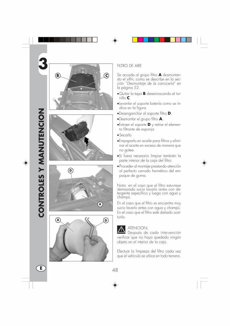
3
CO
NTR
OLE
S Y
MA
NU
TEN
CIO
N
48E
FILTRO DE AIRE
Se accede al grupo filtro A desmontan-do el sillín, como se describe en la sec-ción “Desmontaje de la carrocería” enla página 52.•Quitar la tapa B desenroscando el tor-nillo C.
•Levantar el soporte batería como se in-dica en la figura.
•Desenganchar el soporte filtro D.•Desmontar el grupo filtro A.•Extraer el soporte D y retirar el elemen-to filtrante de esponja.
•Secarlo•Empaparlo en aceite para filtros y elimi-nar el aceite en exceso de manera queno gotee.
•Si fuera necesario limpiar también laparte interior de la caja del filtro.
•Proceder al montaje prestando atenciónal perfecto cerrado hermético del em-paque de goma.
Nota: en el caso que el filtro estuviesedemasiado sucio lavarlo antes con de-tergente específico y luego con agua ychampú.En el caso que el filtro se encuentre muysucio lavarlo antes con agua y champú.En el caso que el filtro esté dañado susti-tuirlo.
ATENCION:Después de cada intervención
verificar que no haya quedado ningúnobjeto en el interior de la caja.
Efectuar la limpieza del filtro cada vezque el vehículo se utilice en todo terreno.
D
A
B C
DA

3
CO
NTR
OLE
S Y
MA
NU
TEN
CIO
N
49 E
BUJIA
Realizar la operación utili-zando guantes de protec-ción para evitar quemadu-ras.
Montar una bujía en buen estado contri-buye a disminuir el gasto de combusti-ble y a un optimo rendimiento del motor.Es preferible quitar la bujía con el motorcaliente (naturalménte prendido) puestoque los depósitos de carbón y el colordel aislamiento dan importantes indica-ciones sobre la carburación, la lubrica-ción y el estado general del motor.En efecto si el color del aislante es blan-co la carburación podría ser demasiado“pobre”, si en cambio el color resultaverde la carburación podría ser dema-siado “rica”. Una carburación correctadebería corresponder al color marrónclaro.Para efectuar el control es suficiente qui-tar el capuchón de la corriente y desen-roscar la bujía, utilizando la llave endotación.Limpiar cuidadosamente los electrodoscon un cepillo de metal. Soplar la bujíacon aire comprimido para evitar queeventuales residuos entren en el motor.Examinar con un calibre de espesor ladistancia entre los electrodos, ésta debeestar comprendida entre 0,6 - 0,7 mm,en el caso no esté comprendida entreéstos valores se puede corregir doblan-do el electrodo de masa.
Comprobar además que no haya ra-jaduras en el aislante o electrodos oxi-dados, en éste caso proceder a su susti-tución.
Nota:Efectuar el control respetando la tablaen pag. 57.
Nota:Lubricar la rosca de la bujía y (con elmotor frio) enroscarla a mano hasta eltope, luego apretarla con la llave.
Nota:•Recomendamos utilizar siempre bujías:URBAN 200 = NGK DR8 EAURBAN 125 = NGK CR7 HSA

3
CO
NTR
OLE
S Y
MA
NU
TEN
CIO
N
50E
FRENO DELANTERO
ComprobaciónPara verificar el estado de desgaste delfreno delantero es suficiente revisar la pin-za la la parte delantera por donde esposible ver las pastillas, las cuales debe-rán tener un espesor de 2 mm de ferodo.En el caso que el espesor fuera inferiorproceder inmediatamente a su sustitución.(ver la sección 5 “Sustituciones” en lapágina 66).
Nota:Efectuar el control respetando los tiem-pos indicados en la tabla en pag. 57.
FRENO TRASERO
ComprobaciónPara verificar el estado de desgaste delfreno trasero es suficiente revisar la pin-za por la parte superior por donde esposible ver las pastillas, las cuales debe-rán tener un espesor de 2 mm de ferodo.En el caso que el espesor fuera inferiorproceder inmediatamente a su sustitución.(ver la sección 5 “Sustituciones” en lapágina 66).
Nota:Efectuar el control respetando los tiem-pos indicados en la tabla en pag. 57.2 mm
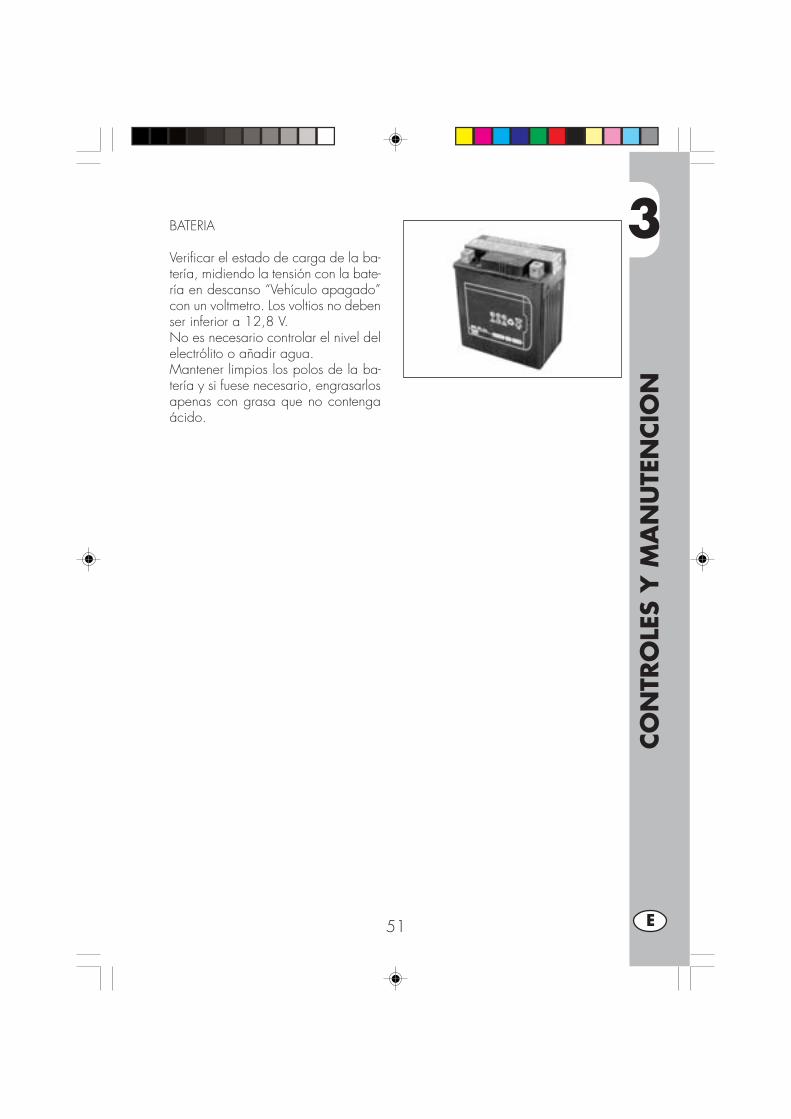
3
CO
NTR
OLE
S Y
MA
NU
TEN
CIO
N
51 E
BATERIA
Verificar el estado de carga de la ba-tería, midiendo la tensión con la bate-ría en descanso “Vehículo apagado”con un voltmetro. Los voltios no debenser inferior a 12,8 V.No es necesario controlar el nivel delelectrólito o añadir agua.Mantener limpios los polos de la ba-tería y si fuese necesario, engrasarlosapenas con grasa que no contengaácido.

3
CO
NTR
OLE
S Y
MA
NU
TEN
CIO
N
52E
DESMONTAJE DE LA CARROCERÍA
Para facilitar los controles y las interven-ciones de mantenimiento se deben des-montar algunas piezas de la carrocería.
ATENCIÓN:El montaje erróneo de estos componen-tes puede producir su desenganche du-rante la marcha con la consiguiente pér-dida de control de la motocicleta.
Desmontaje sillínPara remover el sillín sólo es necesarioquitar los dos tornillos A, la fijación B yla fijación C debajo del sillín.
Nota:Al remover el sillín también se extrae si-multáneamente el guardabarros.Para separar los dos componentes sedeben remover los tres tornillos D.
Desmontaje de las cubiertas deldepósitoPara retirar las cubiertas del depósito Ese debe:• Desenroscar los tornillos F del depósi-
to• Desenroscar las dos fijaciones G, ubi-
cadas en la parte delantera de la mo-tocicleta.
• Quitar las cubiertas del depósito E.
F
E
G
A
B
C
D

3
CO
NTR
OLE
S Y
MA
NU
TEN
CIO
N
53 E
Desmontaje del depósito decombustibleLuego de retirar el sillín, desenroscar eltornillo H que fija el depósito al chasis,quitar el tubo de la válvula del combusti-ble y extraer el depósito hacia la partetrasera
Desmontaje de los carenadoslateralesPara desmontar los dos carenados late-rales L ubicados debajo del depósito enambos lados de la motocicleta, basta conretirar los dos tornillos I.
Desmontaje soporte del grupoóptico delanteroDesenroscar los dos tornillos de fijacióndel faro N, desconectar las conexioneseléctricas del faro, luego desenroscar losdos tornillos M de fijación del soporteportafaro.
H
L
I
N
M

3
CO
NTR
OLE
S Y
MA
NU
TEN
CIO
N
54E
A
B
C
E
D
F
G
H
I
Desmontaje porta-matrículaSe puede desmontar el porta-matrículatrasero A con los faros y los intermiten-tes, después de haber quitado el sillín,(ver la página anterior), y a continuación:•Desenroscar los tres tornillos y sus co-rrespondientes tuercas de fijación B delporta-matrícula del chasis trasero.
•Desconectar la conexión eléctrica delos faros traseros y desmontar el porta-matrícula A.
Atención:El vehículo sin el porta-matrícula y/o sinlos faros, no es conforme con el códigode circulación vigente. El uso se deberestringir sólo a los circuitos privados y/o cerrados a la circulación.
Desmontaje guardabarros delanteroQuitar los cuatro tornillos C y sacar el guar-dabarros delanttero completo.
Desmontaje del caballete•Quitar el par de fijación D (tornillo ytuerca).
•Extraer el caballete E prestando aten-ción al muelle de tracción F.
Notas: prestar atención durante el des-montaje para no dañar el magneto y elsensor del caballete G
Desmontaje estribo pasajero•Destornillar los dos tornillos E indica-dos en la figura y sacar el estribo pa-sajero completo de soporte fijación albastidor.
Desmontaje cerradura cascoPara el desmontaje de la cerradura delcasco se deben retirar los dos tornillos I.
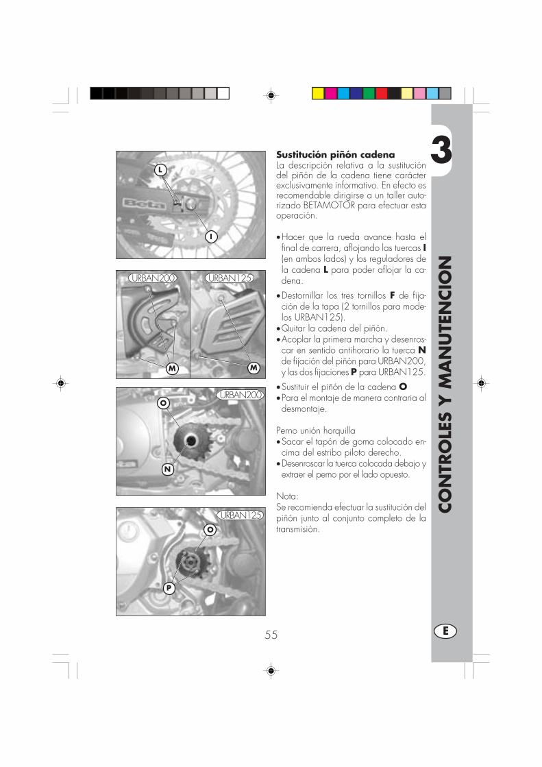
3
CO
NTR
OLE
S Y
MA
NU
TEN
CIO
N
55 E
Sustitución piñón cadenaLa descripción relativa a la sustitucióndel piñón de la cadena tiene carácterexclusivamente informativo. En efecto esrecomendable dirigirse a un taller auto-rizado BETAMOTOR para efectuar estaoperación.
•Hacer que la rueda avance hasta elfinal de carrera, aflojando las tuercas I(en ambos lados) y los reguladores dela cadena L para poder aflojar la ca-dena.
•Destornillar los tres tornillos F de fija-ción de la tapa (2 tornillos para mode-los URBAN125).
•Quitar la cadena del piñón.•Acoplar la primera marcha y desenros-car en sentido antihorario la tuerca Nde fijación del piñón para URBAN200,y las dos fijaciones P para URBAN125.
•Sustituir el piñón de la cadena O•Para el montaje de manera contraria aldesmontaje.
Perno unión horquilla•Sacar el tapón de goma colocado en-cima del estribo piloto derecho.
•Desenroscar la tuerca colocada debajo yextraer el perno por el lado opuesto.
Nota:Se recomienda efectuar la sustitución delpiñón junto al conjunto completo de latransmisión.
I
M
O
N
L
M
P
O
URBAN200 URBAN125
URBAN200
URBAN125

3
CO
NTR
OLE
S Y
MA
NU
TEN
CIO
N
56E
LIMPIEZA DEL VEHICULO Y VERIFICACIONES
Para ablandar la suciedad y el barro depositado en la superficie pintada usar unchorro de agua de baja presión. Una vez ablandado el barro y suciedad se debenquitar con una esponja blanda para carrocería empapada con mucha agua y “champú “ (2-4 % de champú en agua) . Luego enjuagar abundantemente con aguay secar con piel. Para la parte externa del motor usar petrolio, pincel y traposlimpios. El petrolio daña la pintura. Recordamos que para eventual lustrado conceras siliconicas hay que proceder antes a un lavado.
Los detergentes contaminan las aguas. Por lo tanto el lavado del vehículo hayque realizarlo en zona equipada para la recolección y la depuración de
líquidos empleados para el mismo lavado.
El lavado no debe ser nunca realizado bajo el sol especialmente de veranocuando la carrocería está aún caliente puesto que el champú que se seca
antes que el agua puede provocar daños a la pintura. No utilizar nunca traposmojado con gasolina o gasoil para lavar superficies pintadas o de material plásti-co, para evitar que pierdan su brillantez y las características mecánicas de losmateriales.
El uso eventual de hidrolimpiadoras puede dañar los instrumentos, por lotanto se aconseja no dirigir el chorro de agua sobre los componentes eléctri-cos y especialmente hacia la pantalla LCD.
COMPROBACIONES DESPUES DE LA LIMPIEZA
Después de limpiar la moto es buena norma:
• Limpiar el filtro de aire (proceder como descrito en pag. 374)•Engrasar la cadena.

3
CO
NTR
OLE
S Y
MA
NU
TEN
CIO
N
57 E
MANUTENCION PROGRAMADA
Advertencia:
En caso de intervenciones en la moto dirigirse a la cadena de Asistencia Autorizada Betamotor.
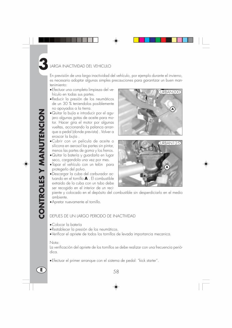
3
CO
NTR
OLE
S Y
MA
NU
TEN
CIO
N
58E
LARGA INACTIVIDAD DEL VEHICULO
En previsión de una larga inactividad del vehículo, por ejemplo durante el invierno,es necesario adoptar algunas simples precauciones para garantizar un buen man-tenimiento:•Efectuar una completa limpieza del ve-hículo en todas sus partes.
•Reducir la presión de los neumáticosde un 30 % teniendolos posiblementeno apoyados a la tierra.
•Quitar la bujía e introducir por el agu-jero algunas gotas de aceite para mo-tor. Hacer gira el motor por algunasvueltas, accionando la palanca arran-que a pedal (donde prevista) . Volver aeroscar la bujía .
•Cubrir con un pelicula de aceite osilicona en aerosol las partes sin pintar,menos las partes de goma y los frenos.
•Quitar la batería y guardarla en lugarseco, cargandola una vez por mes.
•Tapar el vehículo con un telón paraprotegerlo del polvo.
•Descargar la cuba del carburador ac-tuando en el tornillo A . El combustibleextraido de la cuba con un tubo debeser recogido en el interior de un reci-piente y colocado en el depósito del combustible sin desperdiciarlo en el medioambiente.
•Apretar nuevamente el tornillo.
DEPUES DE UN LARGO PERIODO DE INACTIVIDAD
•Colocar la batería•Restablecer la presión de los neumáticos.•Verificar el apriete de todos los tornillos de levada importancia mecanica.
Nota:La verificación del apriete de los tornillos se debe realizar con una frecuencia perió-dica.
•Efectuar el primer arranque con el sistema de pedal: “kick starter“.
A
A
URBAN200
URBAN125

4
REG
ULA
CIO
NES
59 E
INDICE ARGUMENTOS
CAP. 4 REGULACIONES
Regulación frenos
Regulación embregue
Regulación ralentí
Regulación juego gas
Comprobación y regulación juego dirección
Tensionamiento cadena
Haz luminoso
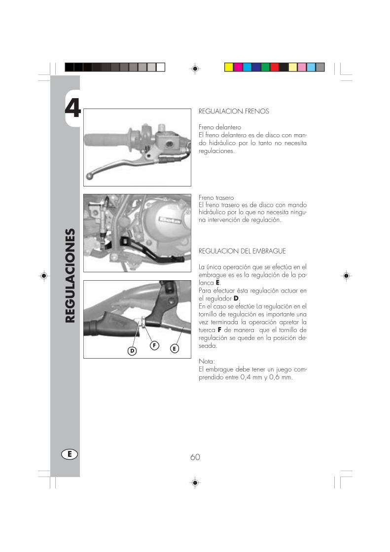
4
REG
ULA
CIO
NES
60E
REGUALACION FRENOS
Freno delanteroEl freno delantero es de disco con man-do hidráulico por lo tanto no necesitaregulaciones.
Freno traseroEl freno trasero es de disco con mandohidráulico por lo que no necesita ningu-na intervención de regulación.
REGULACION DEL EMBRAGUE
La única operación que se efectúa en elembrague es es la regulación de la pa-lanca E.Para efectuar ésta regulación actuar enel regulador D.En el caso se efectúe La regulación en eltornillo de regulación es importante unavez terminada la operación apretar latuerca F de manera que el tornillo deregulación se quede en la posición de-seada.
Nota:El embrague debe tener un juego com-prendido entre 0,4 mm y 0,6 mm.
FD E
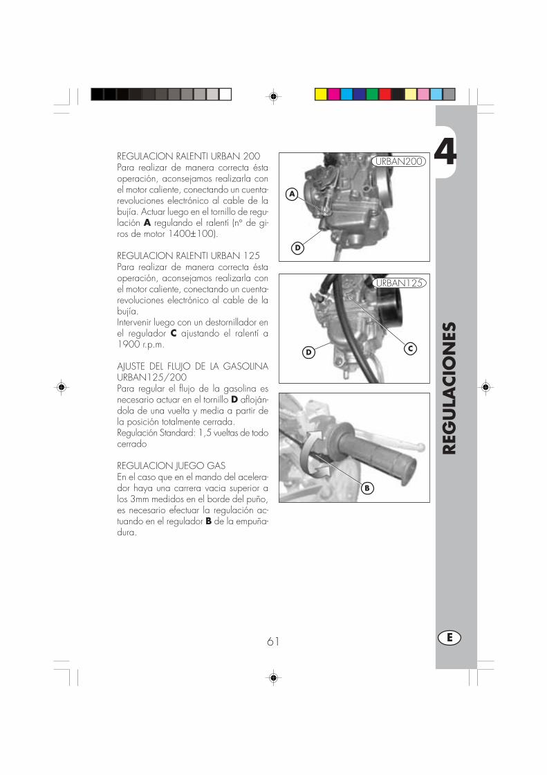
4
REG
ULA
CIO
NES
61 E
REGULACION RALENTI URBAN 200Para realizar de manera correcta éstaoperación, aconsejamos realizarla conel motor caliente, conectando un cuenta-revoluciones electrónico al cable de labujía. Actuar luego en el tornillo de regu-lación A regulando el ralentí (n° de gi-ros de motor 1400±100).
REGULACION RALENTI URBAN 125Para realizar de manera correcta éstaoperación, aconsejamos realizarla conel motor caliente, conectando un cuenta-revoluciones electrónico al cable de labujía.Intervenir luego con un destornillador enel regulador C ajustando el ralentí a1900 r.p.m.
AJUSTE DEL FLUJO DE LA GASOLINAURBAN125/200Para regular el flujo de la gasolina esnecesario actuar en el tornillo D afloján-dola de una vuelta y media a partir dela posición totalmente cerrada.Regulación Standard: 1,5 vueltas de todocerrado
REGULACION JUEGO GASEn el caso que en el mando del acelera-dor haya una carrera vacia superior alos 3mm medidos en el borde del puño,es necesario efectuar la regulación ac-tuando en el regulador B de la empuña-dura.
B
A
CD
D
URBAN200
URBAN125
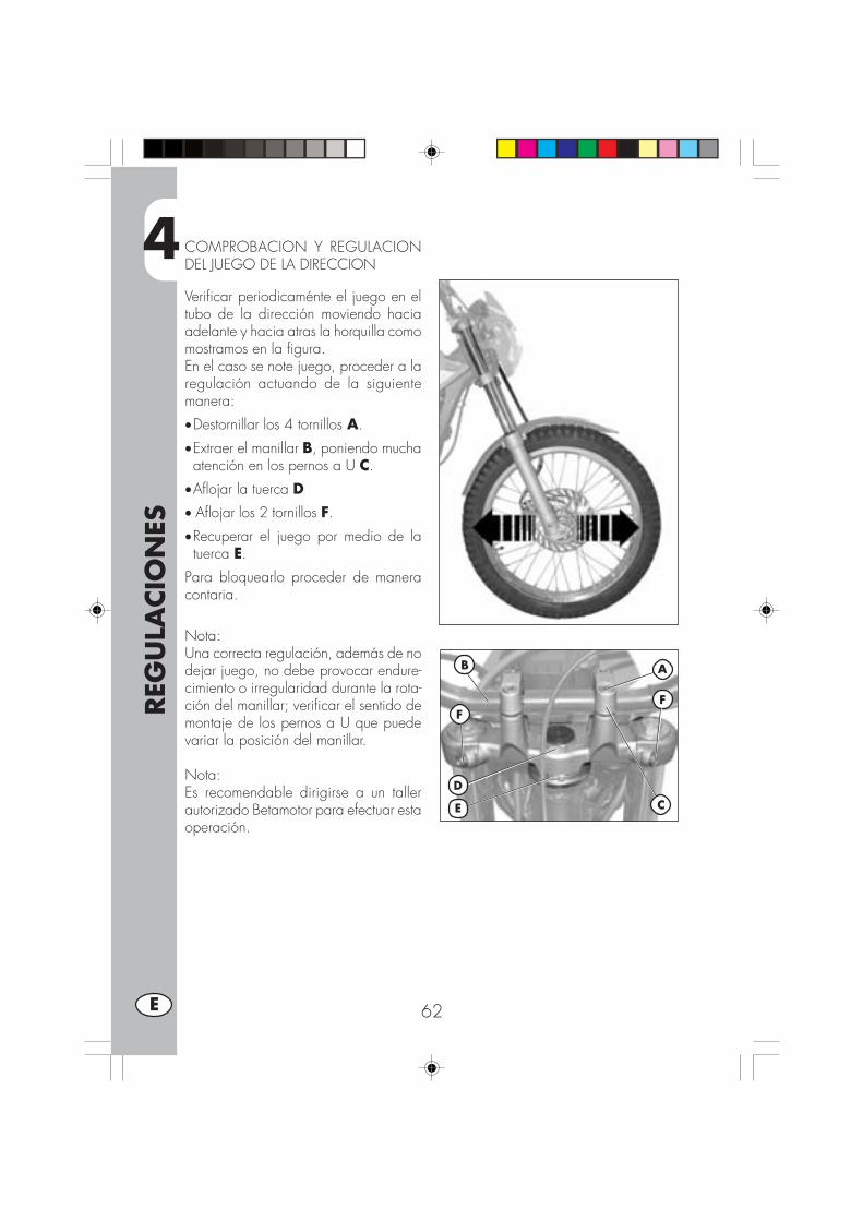
4
REG
ULA
CIO
NES
62E
COMPROBACION Y REGULACIONDEL JUEGO DE LA DIRECCION
Verificar periodicaménte el juego en eltubo de la dirección moviendo haciaadelante y hacia atras la horquilla comomostramos en la figura.En el caso se note juego, proceder a laregulación actuando de la siguientemanera:
•Destornillar los 4 tornillos A.
•Extraer el manillar B, poniendo muchaatención en los pernos a U C.
•Aflojar la tuerca D• Aflojar los 2 tornillos F.
•Recuperar el juego por medio de latuerca E.
Para bloquearlo proceder de maneracontaria.
Nota:Una correcta regulación, además de nodejar juego, no debe provocar endure-cimiento o irregularidad durante la rota-ción del manillar; verificar el sentido demontaje de los pernos a U que puedevariar la posición del manillar.
Nota:Es recomendable dirigirse a un tallerautorizado Betamotor para efectuar estaoperación.
B
D
E C
A
FF

4
REG
ULA
CIO
NES
63 E
TENSIONAMIENTO CADENA
Para una mas larga vida de la cadenadetransmisión es oportuno controlar pe-riodicaménte su tensión.Si el juego de la cadena supera los 20mm proceder al tensionamiento.
•Aflojar las tuerca A en brazo de lahorquilla
•Aflojar la tuerca C en ambos brazosde la horquilla
• Intervenir en la tuerca B hasta que lacadena alcance la tensión deseada
•Proceder de la misma forma intervinien-do en la tuerca B situada en el otrobrazo de la horquilla hasta obtener laalineación perfecta de la rueda
•Apretar las tuercas B y A en ambosbrazos de la horquilla trasera.
20 mm
B
C A

4
REG
ULA
CIO
NES
64E
HAZ LUMINOSO
• La reguilación del haz luminoso se realiza manualménte después de haber destor-nillado con una llave Allen el tornillo ubicado en los lados del grupo optico.
• La otientación del haz luminoso debe ser verificado periodicaménte. La regulaciónes solo vertical.
•Colocar el vehículo (en plano pero no sobre el caballete) a 10 metros de unapared vertical.
•Medir la altura del centro del proyector al suelo y llevar con una cruz en la pareda 9/10 de la altura del farol.
•Encender la luz de cruce, sentarse en la moto y verificar que el haz luminosoproyectado en la pared esté poco debajo de la cruz colocada en la pared.
9/10
h
10 m
h
AA

5
SUST
ITU
CIO
NES
65 E
INDICE DE ARGUMENTOS
CAP. 5 SUSTITUCIONES
Sustitución pastillas freno
Sustitución bombillos faro delantero.
Sustitución bombillos piloto trasero.
Sustitución bombillos indicadores de dirección.
Sustitución bombillos tablero.
Lámparas características

5
SUST
ITU
CIO
NES
66E
SUSTITUCION PASTILLAS FRENO DE-LANTEROLa descripción relativa a la sustitución delas pastillas es de caracter informativopuesto que es aconsejable dirigirse a untaller autorizado Betamotor para efectuarésta operación.
Freno delanteroPara sustituir las pastillas delanteras sedebe proceder de la siguiente manera:
•Desmontar la pinza destornillando losdos tornillos A
•Desenroscar los dos tornillos BNota:los tornillos B están apretados muy fuerte,se recomienda aflojarlos antes de desen-ganchar la pinza de la horquilla•Extraer las pastillas
•Para el montaje proceder de maneracontraria.
Prestar atención que el muelle de la figu-ra esté bien colocado en su propio alo-jamiento, deberá tener un poco de re-sistencia durante la colocación de laspastillas.
Prestar mucha atención al correcto mon-taje de los pasadores para evitar proble-mas de frenada.
En el caso se tenga que desmontar eldisco freno, en el montaje aplicar Loctitea los tornillos.
ATENCION:Durante el desmontaje de la pin-
za del freno prestar atención para evitardaños al reed C puesto que el mismo esmuy delicado.
CD
A
B
B

5
SUST
ITU
CIO
NES
67 E
Freno traseroPara sustituir las pastillas traseras se debeproceder de la siguiente manera:•Retirar el perno de seguridad A•Desenroscar el perno de soporte de laspastillas B
•Desmontar las pastillas C.
•Para montar nuevamente proceder ensentido inverso, prestando especial aten-ción a la ubicación correcta de laspastillas en su alojamiento.
Note:En el caso se tenga que desmontar eldisco freno, en el montaje aplicar Loctitea los tornillos.
A
B
C
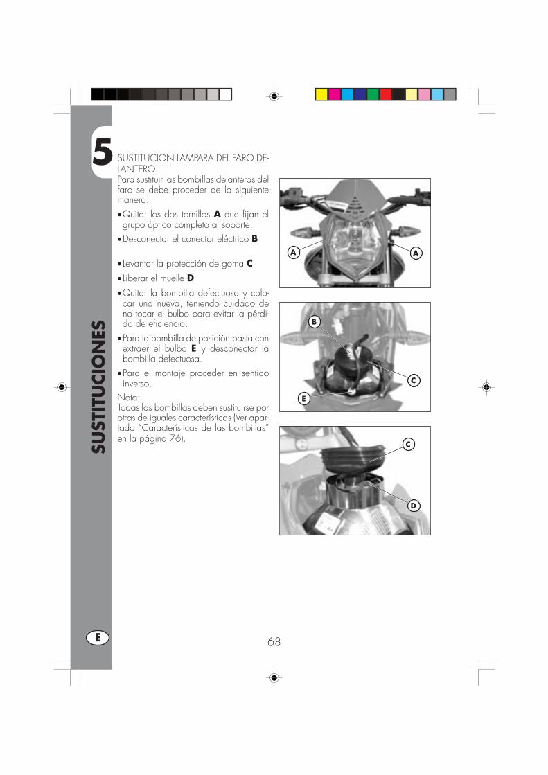
5
SUST
ITU
CIO
NES
68E
SUSTITUCION LAMPARA DEL FARO DE-LANTERO.Para sustituir las bombillas delanteras delfaro se debe proceder de la siguientemanera:•Quitar los dos tornillos A que fijan elgrupo óptico completo al soporte.
•Desconectar el conector eléctrico B
• Levantar la protección de goma C• Liberar el muelle D•Quitar la bombilla defectuosa y colo-car una nueva, teniendo cuidado deno tocar el bulbo para evitar la pérdi-da de eficiencia.
•Para la bombilla de posición basta conextraer el bulbo E y desconectar labombilla defectuosa.
•Para el montaje proceder en sentidoinverso.
Nota:Todas las bombillas deben sustituirse porotras de iguales características (Ver apar-tado “Características de las bombillas”en la página 76).
AA
B
C
C
D
E

5
SUST
ITU
CIO
NES
69 E
SUSTITUCION BOMBILLO DEL PILOTOTRASEROPara sustituir el grupo faro trasero A sedebe proceder de la siguiente manera:•Desmontar el porta-matrícula como seindica en la sección “Desmontaje de lacarrocería” en la página 60
•Desconectar todas las conexiones eléc-tricas
•Desenroscar los dos tornillos B ubica-dos debajo del guardabarros
•Extraer el grupo faro A defectuoso ysustituirlo con uno nuevo.
•Para el montaje proceder en sentidoinverso.
Nota:Todas las bombillas deben sustituirse porotras de iguales características (Ver apar-tado “Características de las bombillas”en la página 76).
SUSTITUCION LÁMPARA ALUMBRA-DO MATRÌCULAPara sustituir la bombilla de la luz dematrícula se debe:•Desenroscar el tornillo C•Quitar el plástico transparente D•Desconectar la bombilla defectuosa delbulbo y sustituirla con otra nueva.
•Para el montaje proceder en sentidoinverso.
Nota:Todas las bombillas deben sustituirse porotras de iguales características (Ver apar-tado “Características de las bombillas”en la página 76).
A
B
CD
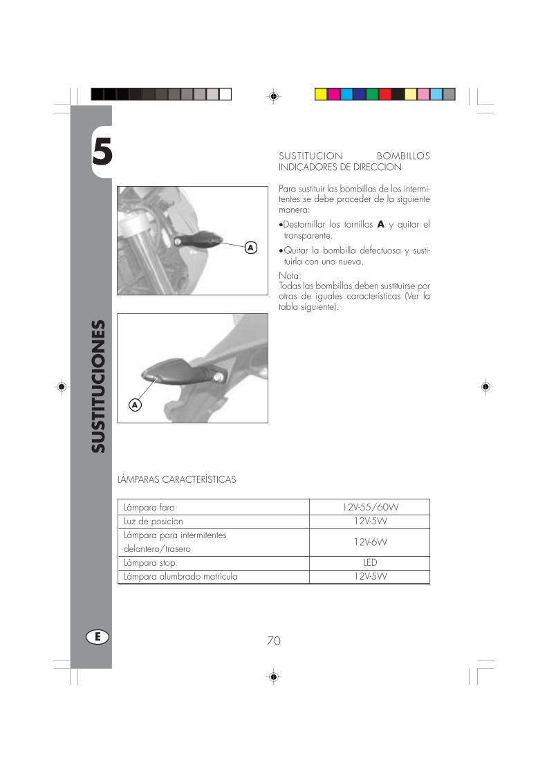
5
SUST
ITU
CIO
NES
70E
SUSTITUCION BOMBILLOSINDICADORES DE DIRECCION
Para sustituir las bombillas de los intermi-tentes se debe proceder de la siguientemanera:
•Destornillar los tornillos A y quitar eltransparente.
•Quitar la bombilla defectuosa y susti-tuirla con una nueva.
Nota:Todas las bombillas deben sustituirse porotras de iguales características (Ver latabla siguiente).
A
A
Lámpara faro 12V-55/60WLuz de posicion 12V-5WLámpara para intermitentesdelantero/trasero
12V-6W
Lámpara stop. LEDLámpara alumbrado matrìcula 12V-5W
LÁMPARAS CARACTERÍSTICAS

6
QU
E H
ACER
EN
CA
SO D
E EM
ERG
ENCIA
71 E
INDICE DE LOS ARGUMENTOS
CAP. 6 QUE HACER EN CASO DE MERGENCIA
INDICE ALFABETICO
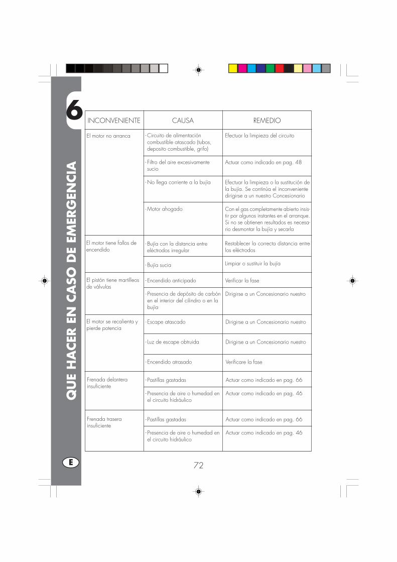
6
QU
E H
ACER
EN
CA
SO D
E EM
ERG
ENCIA
72E
INCONVENIENTE CAUSA
El motor no arranca
REMEDIO
- Circuito de alimentacióncombustible atascado (tubos,deposito combustible, grifo)
- Filtro del aire excesivamentesucio
- No llega corriente a la bujía
- Motor ahogado
Efectuar la limpieza del circuito
Actuar como indicado en pag. 48
Efectuar la limpieza o la sustitución dela bujía. Se continúa el inconvenientedirigirse a un nuestro Concesionario
Con el gas completamente abierto insis-tir por algunos instantes en el arranque.Si no se obtienen resultados es necesa-rio desmontar la bujía y secarla
El motor tiene fallos deencendido
- Bujía con la distancia entreeléctrodos irregular
- Bujía sucia
Restablecer la correcta distancia entrelos eléctrodos
Limpiar o sustituir la bujía
El pistón tiene martilleosde válvulas
- Encendido anticipado
- Presencia de depósito de carbónen el interior del cilindro o en labujía
Verificar la fase
Dirigirse a un Concesionario nuestro
El motor se recalienta ypierde potencia
- Escape atascado
- Luz de escape obtruida
- Encendido atrasado
Dirigirse a un Concesionario nuestro
Dirigirse a un Concesionario nuestro
Verificare la fase
Frenada delanterainsuficiente
- Pastillas gastadas
- Presencia de aire o humedad enel circuito hidráulico
Actuar como indicado en pag. 66
Actuar como indicado en pag. 46
Frenada traserainsuficiente
- Pastillas gastadas
- Presencia de aire o humedad enel circuito hidráulico
Actuar como indicado en pag. 66
Actuar como indicado en pag. 46

IND
ICE
ALF
ABET
ICO
73 I
Abastecimiento combustible ................................................................... 40Aceite bomba frenos ............................................................................ 45Aceite horquilla ................................................................................... 47Aceite motor: control y sustitución URBAN200........................................... 42Aceite motor: control y sustitución URBAN200........................................... 44Arranque ............................................................................................ 38
Busca de inconveniente ......................................................................... 71
Cerradura casco .................................................................................. 12Conmutador / bloquéo dirección ........................................................... 12Controles después de la limpieza............................................................ 56Controles y manutención antes y después del utilizo en todo terreno .............. 36
Datos identificación vehículo .................................................................... 8Datos técnicos ..................................................................................... 24Dirección: control y regulación ............................................................... 62
Embrague ........................................................................................... 60Espurgo frenos ..................................................................................... 45Esquema eléctrico URBAN125 ............................................................... 28Esquema eléctrico URBAN200 ............................................................... 30
Filtro aire ............................................................................................ 48Freno delantero control y sustitución ......................................................... 66Freno trasero control y sustitución ............................................................ 66
Llaves ................................................................................................ 12Lubricantes y líquidos aconsejados .......................................................... 37LCD ................................................................................................... 14
Manutención programada ..................................................................... 57
Regulación embrague ........................................................................... 60Regulación frenos ................................................................................. 60Regulación juego gas ........................................................................... 61Regulación mínimo ............................................................................... 61Rodaje ............................................................................................... 37
Sustitución lámparas ............................................................................. 68
Tablero y mandos ................................................................................ 13Tensionamiento cadena ......................................................................... 63

Edition April 2008