urban sketcher: creating urban scenery using multimodal ... · urban sketcher: creating urban...
TRANSCRIPT
Urban Sketcher: Creating Urban Scenery UsingMultimodal Interfaces on Large Screen Displays
José Pedro DiasInstituto Superior Técnico
Av. Prof. Dr. Aníbal Cavaco Silva2744-016 Porto Salvo, Portugal
Joaquim A. JorgeInstituto Superior Técnico
Av. Rovisco Pais1049-001 Lisboa, Portugal
ABSTRACTA system was developed for the creation of urban scenarios pro-duced on large screen displays using laser pointers as input devicesand supporting collaborative usage. A novel interface had to be de-veloped to support interaction with such input devices, based on theconcept of gates and circular menus with a non-intrusive interface.
Users can navigate on a virtual world using a set of comprehen-sive navigation modes, namely: first person, bird’s eye view andexamine modes, along with a multimodal flight mode controlled byspeech commands and arm tracking. Simple shapes can be createdand modeled using a minimalistic set of modeling tools, defining anovel modeling interface. Buildings can be instantiated from a li-brary of facade styles by drawing the desired blueprint and settingthe facade height to generate unique buildings. Additional stylesmay be implemented by making use of a developed XML formatfor defining façade layout rules. Buildings and other shapes can betransformed and cloned. Objects in the scene can have notes at-tached to them to aid in reviewing sessions. An alternative buildingcreation work flow is proposed to take advantage of this system forearly prototypes and showcasing projects.
Keywordsstroke, building, multimodal, large screen, BREP
1. INTRODUCTIONWith the advent of advanced visualization hardware it is now pos-sible to interact with complex representations of urban scenarios.There is a myriad of systems supporting the modeling of three-dimensional content but they tend to be overly complex and makeuse of concepts focused on mouse and keyboard interaction. Thereis a demand for systems capable of offering 3D scenes renderingand supporting multi-user interaction on large screens on fields sodisparate as architecture and the entertainment industry.
This project aims at offering a simple to learn interface for collab-orative interaction on large screen displays. It supports both laserpointers and a multimodal arms motion tracking plus speech recog-nition modes: the former for controlling actions, navigation andmodeling; the latter for an alternative, hands-free flying navigationmode.
The application of such interface is a system for fast creation of citylandscapes by means of instancing template-based building stylesthe minimal set of strokes, along with a modeling tool kit capableof editing 3D shapes by manipulating its faces and edges throughtheir most common directions.
The state of the art in this domain was sought out. No project map-ping the objectives of this project has been developed though some,due to their dimension or common ground, were subject of analysis.
Work from other authors was reviewed when it addressed relevantproblems, subject of usage on the project. The most well knownsoftware bundles were compared to analyze possible solutions andavoid common mistakes.
Developing an application for such purposes requires dealing withseveral aspects – the large scale rendering of the scenario, givingpeople means to interact with the screen, allowing people to inter-act at the same time and offering a simple interface adapted to therunning environment. Several navigation modes were developedto enhance the user experience, most notably a multimodal flightmode controlled by the user arms motion and triggered by voicecommands. A set of rules was designed so building templates couldbe created and instanced easily on the scene. A set of modeling op-erations was defined and implemented so a novice user could per-form simple yet effective modeling operations to enrich the scenewith details.
This system’s interface was set for large screen displays and laserpointers chosen as the main source of user input due to it beingboth portable and light. The usage of laser pointers issues the prob-lem that a laser pointer can not be tracked while the light is notturned on. Clicking behaviors are hard to detect and users can notbe precise while unable to view the laser pointer’s projection on thescreen. An alternate interface urged to solve this issue – instead ofthe commonly used buttons and drop-down menus, crossable areasand ring shaped menus were introduced. These menus can be in-voked where needed by issuing a closed triangle gesture, to betterexplore the available space on the screen.
The design and development of this system was routinely testedwith users for detailing the layout of menus, readability of thefeatured action icons and validate innovative features, namely theflight mode, template-based instancing of buildings and shape mod-eling tools.
At the final usability tests, for every mappable feature, tasks wereperformed on both Urban Sketcher and other system – Google SketchUp1.Even though GSU relies on desktop concepts and input/output de-vices, users were able to perform the tasks successfully and tookless than twice the time performing them using such devices and in-terface. Users easily learned the system’s features and their menus,being able to easily create 3D content such as buildings (template-based) and custom objects (using a tool set of simple modelingtools).
This project takes advantage of large screen displays, made pos-sible by the devised interface based on area activation and ringmenus, with users applying discrete strokes using laser pointers.The navigation and shape creation functionalities focused on sim-
1Google SketchUp – http://www.sketchup.com
plicity, offering a set of tools and the capability to extend the soft-ware with additional scenarios and facade styles. A novel set ofmodeling tools and interaction gestures was put to work, with em-phasis on a multimodal flight navigation mode.
Following is the related work chapter where a set of solutions de-vised by other authors are discussed. A comparative analysis oncommercial software bundles is performed to emphasize their ad-vantages and avoid their flaws. The design chapter is next, describ-ing the broad view of the Urban Sketcher project, its architecture,modules and purpose. The concepts used throughout this documentare defined here. Subsequently one can find the implementationchapter, where the various navigation modes are defined and justi-fied, as are the content creation, editing and review features whichmake part of the system. An alternative cityscape drafting work-flow is then suggested taking advantage of the system developed.The process of evaluation is described, presented and discussed onthe evaluation chapter. The document ends stating the results whichhave been reached, the main contributions this project introducesand ways it can be enhanced in the future.
2. RELATED WORKThis section is the result of researching existing academic and com-mercial software systems and publications. Since no prior systemswith these requirements could be determined, related work wassought to cover subproblems related to the design and implementa-tion of such a system.
Three systems are discussed in this area, each one withstandingcommon goals with the idealized solution.
2.0.1 ARVIKA, 2003ARVIKA [6] is a project with sponsoring from the German FederalMinistry of Education and Research that was implemented between1999 and 2003. It focused on the development of Augmented Re-ality (AR) technologies to aid in performing industrial tasks.
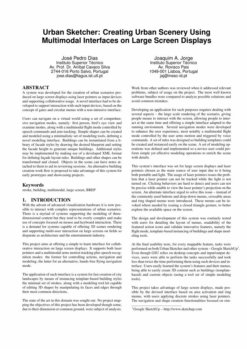
An expert in the industrial area would carry a head-mounted display(HMD) with a camera mounted on it. The real-time captured videowas then interpreted and markers extracted from the image. Thecamera’s positioning and orientation were estimated and the HMDview was enriched with virtual objects (see figure 1, left). Theframework was distributed in the form of an ActiveX plug-in forthe Internet Explorer browser named ARBrowser.
Figure 1: HMD augmented view; a user of the ARVIKA system
Weidenhausen et al. [9] consider the deployment of the project asan ActiveX component to be an advantage since it is based on awidespread program (Internet Explorer) and allowed developers tocreate task scenarios with familiar technologies such as JavaScriptand HTML. Although the world’s largest research project in thearea, ARVIKA focused too much on the technical problems re-garding AR and little effort was spent on the creation of a suit-able user interface. The authors agree on a point: “most peoplejudge the usefulness of a technology mainly by its user interface”.ARVIKA was meant to support many industrial scenarios – devel-opment, production and services for several industrial partners on
different domains. Creating a scenario was a time consuming task– taking several days, according to Weidenhausen et al. – and re-quired extensive knowledge in 3D modeling tools and VRML. Noauthoring capabilities were given to end-users. This problem wasidentified as paramount and an authoring tool was scheduled for fu-ture development, supporting generic task creation with parameterscontrolled by the users.
2.0.2 Speech & Gestures on Multi-user Tabletop, 2006Tse et al. [16] developed a multimodal interface on top of GoogleEarth2 to be run on a multi-touch table. The system allows multi-user collaboration with touch and voice commands.
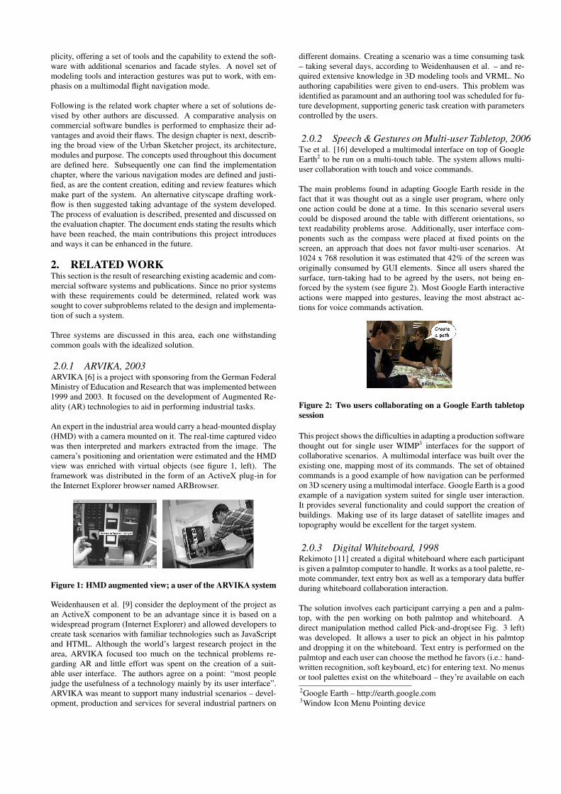
The main problems found in adapting Google Earth reside in thefact that it was thought out as a single user program, where onlyone action could be done at a time. In this scenario several userscould be disposed around the table with different orientations, sotext readability problems arose. Additionally, user interface com-ponents such as the compass were placed at fixed points on thescreen, an approach that does not favor multi-user scenarios. At1024 x 768 resolution it was estimated that 42% of the screen wasoriginally consumed by GUI elements. Since all users shared thesurface, turn-taking had to be agreed by the users, not being en-forced by the system (see figure 2). Most Google Earth interactiveactions were mapped into gestures, leaving the most abstract ac-tions for voice commands activation.
Figure 2: Two users collaborating on a Google Earth tabletopsession
This project shows the difficulties in adapting a production softwarethought out for single user WIMP3 interfaces for the support ofcollaborative scenarios. A multimodal interface was built over theexisting one, mapping most of its commands. The set of obtainedcommands is a good example of how navigation can be performedon 3D scenery using a multimodal interface. Google Earth is a goodexample of a navigation system suited for single user interaction.It provides several functionality and could support the creation ofbuildings. Making use of its large dataset of satellite images andtopography would be excellent for the target system.
2.0.3 Digital Whiteboard, 1998Rekimoto [11] created a digital whiteboard where each participantis given a palmtop computer to handle. It works as a tool palette, re-mote commander, text entry box as well as a temporary data bufferduring whiteboard collaboration interaction.
The solution involves each participant carrying a pen and a palm-top, with the pen working on both palmtop and whiteboard. Adirect manipulation method called Pick-and-drop(see Fig. 3 left)was developed. It allows a user to pick an object in his palmtopand dropping it on the whiteboard. Text entry is performed on thepalmtop and each user can choose the method he favors (i.e.: hand-written recognition, soft keyboard, etc) for entering text. No menusor tool palettes exist on the whiteboard – they’re available on each2Google Earth – http://earth.google.com3Window Icon Menu Pointing device
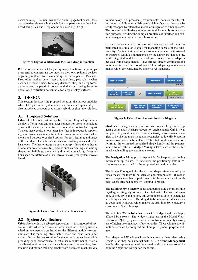
user’s palmtop. The main window is a multi page tool panel. Userscan store data elements in this window and paste them to the white-board using Pick-and-Drop operations. (see Fig. 3 right).
Figure 3: Digital Whiteboard: Pick-and-drop interaction
Rekimoto concludes that by putting many functions on palmtops,users tend to concentrate too much on their own palmtop devices,degrading mutual awareness among the participants. Pick-and-Drop often worked better than drag-and-drop, particularly whenuser had to move objects for a long distance. Drag-and-drop forcesa user to keep the pen tip in contact with the board during the entireoperation, a restriction not suitable for large display surfaces.
3. DESIGNThis section describes the proposed solution, the various moduleswhich take part in the system and each module’s responsibility. Italso introduces concepts used extensively throughout the solution.
3.1 Proposed SolutionUrban Sketcher is a system capable of controlling a large screendisplay, offering conventional laser pointers for users to be able todraw on the screen, with multi-user cooperative control (see Fig.4).To meet these goals, a novel user interface is introduced, support-ing multi-user laser interaction, free invocation and dismissal ofmenus and purpose-organized options for easy learning and usageof the interface. The interface is based on crossing areas and circu-lar menus. The heavy usage on such concepts drove the author todevise new ways of executing actions such as creating and editingshapes and buildings, scene navigation and note taking. Most ac-tions span the lifetime of a laser stroke, making the system stroke-based.
Figure 4: Urban Sketcher interaction scenario
3.2 System ArchitectureUrban Sketcher is a distributed application – it is composed of sev-eral modules which can run on different machines, making use of awired intranet network on the lab for the different modules to com-municate. The rendering infrastructure based on OpenSG computernodes offers a cheaper solution for rendering large surfaces whileproviding good performance. Most other modules benefit from adistributed environment – tasks such as speech recognition, lasertracking and motion tracking benefit from dedicated machines due
to their heavy CPU processing requirements; modules for integrat-ing input modalities establish standard interfaces so they can beeasily swapped by alternative media or integrated to other systems.The core and middle-tier modules are modular mainly for abstrac-tion purposes, dividing the complex problems of interface and con-tent management into manageable solutions.
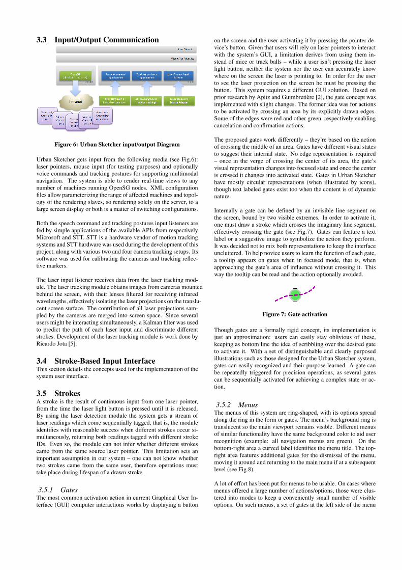
Urban Sketcher composed of a set of modules, most of them im-plemented as singleton classes for managing subsets of the func-tionality. The interaction between system components is illustratedon Figure 5. Modules implemented by the author are shaded blue,while integrated modules are shaded green. A set of input adaptersget data from several media – laser strokes, speech commands andmotion tracked markers’ coordinates. These adapters generate com-mands which are consumed by higher level managers.
Figure 5: Urban Sketcher Architecture Diagram
Strokes are managed and at low level, with key stroke gestures trig-gering commands. A shape recognition engine named Cali [1] wasintegrated to provide shape detection on two types of strokes: trian-gles, to invoke the main menu and rectangles, to identify blueprintsketches over construction planes. Cali is fed polyline information,returning the estimated recognized shape family and its parame-ters, if found. The 2D Widget Manager takes care of the visibleinterface, handling gate and menu events.
The Navigation Manager is responsible for keeping positioninginformation up to date. It transforms the positioning state in re-sponse to actions issued by the supported navigation modes.
The Shape Manager holds the existing shape references and pro-vides means for them to be selected and manipulated. It cachesloaded shapes to enhance performance in the generation of build-ings, where attached geometry is bound to repeat.
The Building Style Factory loads and parses style definitions intofaçade-generating algorithms. Once fed with blueprint informa-tion, desired style and height, this component is able to instantiatea building and its details. Building details are attached shapes suchas doors and windows, which makes the Building Style Factory aconsumer of Shape Manager.
The 2D Gate/Menu Interface is a set of widgets and their logic,affected by strokes. The widgets make use of the Model-View-Controller [7] design pattern, with the controller ultimately makinguse of higher level managers functionalities. These widgets are of-tentimes created by composition of simpler, general purpose wid-gets.
Both shapes and 2D widgets know how to render themselves usingOpenSG, so they both interact with it. 3D Scene Managementhandles the representation of the virtual world and is controlled byboth the Shape and Navigation managers.
3.3 Input/Output Communication
Figure 6: Urban Sketcher input/output Diagram
Urban Sketcher gets input from the following media (see Fig.6):laser pointers, mouse input (for testing purposes) and optionallyvoice commands and tracking postures for supporting multimodalnavigation. The system is able to render real-time views to anynumber of machines running OpenSG nodes. XML configurationfiles allow parameterizing the range of affected machines and topol-ogy of the rendering slaves, so rendering solely on the server, to alarge screen display or both is a matter of switching configurations.
Both the speech command and tracking postures input listeners arefed by simple applications of the available APIs from respectivelyMicrosoft and STT. STT is a hardware vendor of motion trackingsystems and STT hardware was used during the development of thisproject, along with various two and four camera tracking setups. Itssoftware was used for calibrating the cameras and tracking reflec-tive markers.
The laser input listener receives data from the laser tracking mod-ule. The laser tracking module obtains images from cameras mountedbehind the screen, with their lenses filtered for receiving infraredwavelengths, effectively isolating the laser projections on the translu-cent screen surface. The contribution of all laser projections sam-pled by the cameras are merged into screen space. Since severalusers might be interacting simultaneously, a Kalman filter was usedto predict the path of each laser input and discriminate differentstrokes. Development of the laser tracking module is work done byRicardo Jota [5].
3.4 Stroke-Based Input InterfaceThis section details the concepts used for the implementation of thesystem user interface.
3.5 StrokesA stroke is the result of continuous input from one laser pointer,from the time the laser light button is pressed until it is released.By using the laser detection module the system gets a stream oflaser readings which come sequentially tagged, that is, the moduleidentifies with reasonable success when different strokes occur si-multaneously, returning both readings tagged with different strokeIDs. Even so, the module can not infer whether different strokescame from the same source laser pointer. This limitation sets animportant assumption in our system – one can not know whethertwo strokes came from the same user, therefore operations musttake place during lifespan of a drawn stroke.
3.5.1 GatesThe most common activation action in current Graphical User In-terface (GUI) computer interactions works by displaying a button
on the screen and the user activating it by pressing the pointer de-vice’s button. Given that users will rely on laser pointers to interactwith the system’s GUI, a limitation derives from using them in-stead of mice or track balls – while a user isn’t pressing the laserlight button, neither the system nor the user can accurately knowwhere on the screen the laser is pointing to. In order for the userto see the laser projection on the screen he must be pressing thebutton. This system requires a different GUI solution. Based onprior research by Apitz and Guimbretière [2], the gate concept wasimplemented with slight changes. The former idea was for actionsto be activated by crossing an area by its explicitly drawn edges.Some of the edges were red and other green, respectively enablingcancelation and confirmation actions.
The proposed gates work differently – they’re based on the actionof crossing the middle of an area. Gates have different visual statesto suggest their internal state. No edge representation is required– once in the verge of crossing the center of its area, the gate’svisual representation changes into focused state and once the centeris crossed it changes into activated state. Gates in Urban Sketcherhave mostly circular representations (when illustrated by icons),though text labeled gates exist too when the content is of dynamicnature.
Internally a gate can be defined by an invisible line segment onthe screen, bound by two visible extremes. In order to activate it,one must draw a stroke which crosses the imaginary line segment,effectively crossing the gate (see Fig.7). Gates can feature a textlabel or a suggestive image to symbolize the action they perform.It was decided not to mix both representations to keep the interfaceuncluttered. To help novice users to learn the function of each gate,a tooltip appears on gates when in focused mode, that is, whenapproaching the gate’s area of influence without crossing it. Thisway the tooltip can be read and the action optionally avoided.
Figure 7: Gate activation
Though gates are a formally rigid concept, its implementation isjust an approximation: users can easily stay oblivious of these,keeping as bottom line the idea of scribbling over the desired gateto activate it. With a set of distinguishable and clearly purposedillustrations such as those designed for the Urban Sketcher system,gates can easily recognized and their purpose learned. A gate canbe repeatedly triggered for precision operations, as several gatescan be sequentially activated for achieving a complex state or ac-tion.
3.5.2 MenusThe menus of this system are ring-shaped, with its options spreadalong the ring in the form or gates. The menu’s background ring istranslucent so the main viewport remains visible. Different menusof similar functionality have the same background color to aid userrecognition (example: all navigation menus are green). On thebottom-right area a curved label identifies the menu title. The top-right area features additional gates for the dismissal of the menu,moving it around and returning to the main menu if at a subsequentlevel (see Fig.8).
A lot of effort has been put for menus to be usable. On cases wheremenus offered a large number of actions/options, those were clus-tered into modes to keep a conveniently small number of visibleoptions. On such menus, a set of gates at the left side of the menu
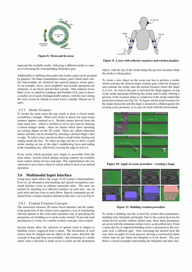
Figure 8: Menu and its areas
represent the available modes. Selecting a different mode is a mat-ter of activating the corresponding illustrative gate.
Additionally to splitting menu gates into modes, gates can be groupedby purpose. On shape manipulation menus, gates which share sim-ilar functionality are clustered into general purpose action gates.As an example: move, move neighbors and extrude operations areclustered, as are bevel and beveled extrude. This solution favorsHick’s Law as stated by Landauer and Nachbar [10], since it showsa smaller set of easily distinguishable options, with the user settingthe exact action he intends to reach from a smaller, filtered set ofgates.
3.5.3 Stroke GesturesTo invoke the main menu the user needs to draw a closed strokeresembling a triangle. When such stroke is drawn one main menuinstance appears centered on it. Besides menus derived from themain menu tree – which is invoked as we’ve just seen by drawinga closed triangle stroke – there are menus which allow operatingon existing shapes on the 3D world. These are called contextualmenus and they can be invoked by selecting a desired shape’s faceor edge. To select a face one has to draw a small stroke starting andending inside the face. To select an edge one has to draw a smallstroke starting on one of the edge’s neighboring faces and endingat the remaining one, effectively crossing the edge to select it.
Every action which generates new shapes is accessible from themain menu. Actions which change existing contents are availablefrom context menus for face and edge. This segmentation rule wasenforced so users know where to search when in need of an untriedoperation.
3.6 Multimodal Input InterfaceUsing laser input allows the usage of all system’s functionalities.Even so, an alternative arm-tracking and speech recognition com-mand interface exists to enhance particular tasks. The arms aretracked by attaching two reflective markers on each arm: one oneach wrist and one close to each elbow. Speech commands are ob-tained from a wireless headset attached to the user’s ear (see Fig.9).
3.6.1 Content Creation ConceptsThe interaction between 2D menu based interface and the under-lying projection of the virtual scene required a way of transferringselected options to the scene and a dynamic way of specifying theparameters of a building so it can be easily created. To provide suchmechanisms to work, two content creation concepts were created.
Several menus allow the selection of options (such as shapes orbuilding styles), triggered from a menu. The destination of suchchoice must be mapped into an object on the scene, therefore theconcept of drag and drop was extended – the remaining of a strokewhere such a selection is made server to point out the destination
Figure 9: A user with reflective markers and wireless headset
object, with the tip of the stroke being the preview location whilethe stroke is taking place.
To create a new object on the scene one has to perform a strokewhich activates the desired shape creation gate (cube for instance)and continue the stroke onto the desired location where the shapeis to rest. As soon as the gate is activated the shape appears on topof the stroke and keeps following the stroke until it ends, offering apreview of the location where is would rest if the stroke ended thatparticular moment (see Fig.10). To figure out the actual location forthe shape during the task the shape is iteratively collided against theexisting scene geometry so it stays in touch with the environment.
Figure 10: Apply-to-scene procedure - creating a shape
Figure 11: Building creation procedure
To create a building one has to feed the system three parameters:building style, blueprint and height. Due to the system decision forstroke-driven actions without global state, these three parametersare given with the minimum strokes (two), as described next. Froma menu the list of supported building styles is presented to the user,each style a different gate. Once activating the desired style theuser starts an apply-to-scene process, moving a construction planewhich must be put where the blueprint is to be drawn. The userdraws a closed rectangle representing the blueprint and after clos-
ing it continues the stroke upwards in order to define the building’sheight. Once the stroke ends the building is generated according tothe given parameters. The construction plane has now carried outits purpose and therefore is terminated (see Fig.11).
4. IMPLEMENTATIONThe execution of the projected features described earlier on is thefocus of this section. Functionalities are grouped by purpose andtheir details explained and discussed. The several offered naviga-tion modes, content creation and editing features and review fea-tures are described. To close this section, an alternative work flowis proposed for taking advantage of the Urban Sketcher features.
4.1 NavigationGood navigation modes are paramount for the success of any 3Dbased system. The nature of this system, with the availability ofa large screen, stroke-controlled input and the aim of allowing un-experienced users to take control of the system quickly, made thisrequirement even more relevant.
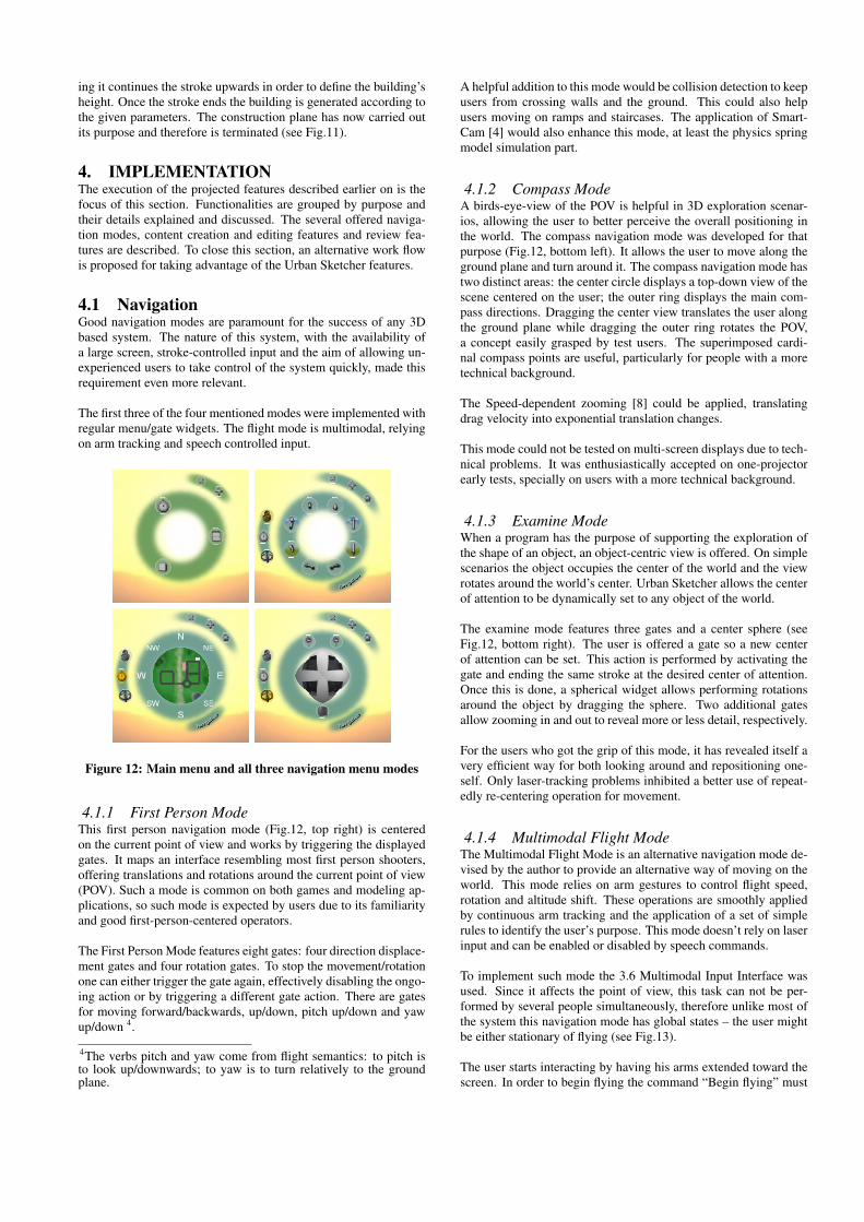
The first three of the four mentioned modes were implemented withregular menu/gate widgets. The flight mode is multimodal, relyingon arm tracking and speech controlled input.
Figure 12: Main menu and all three navigation menu modes
4.1.1 First Person ModeThis first person navigation mode (Fig.12, top right) is centeredon the current point of view and works by triggering the displayedgates. It maps an interface resembling most first person shooters,offering translations and rotations around the current point of view(POV). Such a mode is common on both games and modeling ap-plications, so such mode is expected by users due to its familiarityand good first-person-centered operators.
The First Person Mode features eight gates: four direction displace-ment gates and four rotation gates. To stop the movement/rotationone can either trigger the gate again, effectively disabling the ongo-ing action or by triggering a different gate action. There are gatesfor moving forward/backwards, up/down, pitch up/down and yawup/down 4.
4The verbs pitch and yaw come from flight semantics: to pitch isto look up/downwards; to yaw is to turn relatively to the groundplane.
A helpful addition to this mode would be collision detection to keepusers from crossing walls and the ground. This could also helpusers moving on ramps and staircases. The application of Smart-Cam [4] would also enhance this mode, at least the physics springmodel simulation part.
4.1.2 Compass ModeA birds-eye-view of the POV is helpful in 3D exploration scenar-ios, allowing the user to better perceive the overall positioning inthe world. The compass navigation mode was developed for thatpurpose (Fig.12, bottom left). It allows the user to move along theground plane and turn around it. The compass navigation mode hastwo distinct areas: the center circle displays a top-down view of thescene centered on the user; the outer ring displays the main com-pass directions. Dragging the center view translates the user alongthe ground plane while dragging the outer ring rotates the POV,a concept easily grasped by test users. The superimposed cardi-nal compass points are useful, particularly for people with a moretechnical background.
The Speed-dependent zooming [8] could be applied, translatingdrag velocity into exponential translation changes.
This mode could not be tested on multi-screen displays due to tech-nical problems. It was enthusiastically accepted on one-projectorearly tests, specially on users with a more technical background.
4.1.3 Examine ModeWhen a program has the purpose of supporting the exploration ofthe shape of an object, an object-centric view is offered. On simplescenarios the object occupies the center of the world and the viewrotates around the world’s center. Urban Sketcher allows the centerof attention to be dynamically set to any object of the world.
The examine mode features three gates and a center sphere (seeFig.12, bottom right). The user is offered a gate so a new centerof attention can be set. This action is performed by activating thegate and ending the same stroke at the desired center of attention.Once this is done, a spherical widget allows performing rotationsaround the object by dragging the sphere. Two additional gatesallow zooming in and out to reveal more or less detail, respectively.
For the users who got the grip of this mode, it has revealed itself avery efficient way for both looking around and repositioning one-self. Only laser-tracking problems inhibited a better use of repeat-edly re-centering operation for movement.
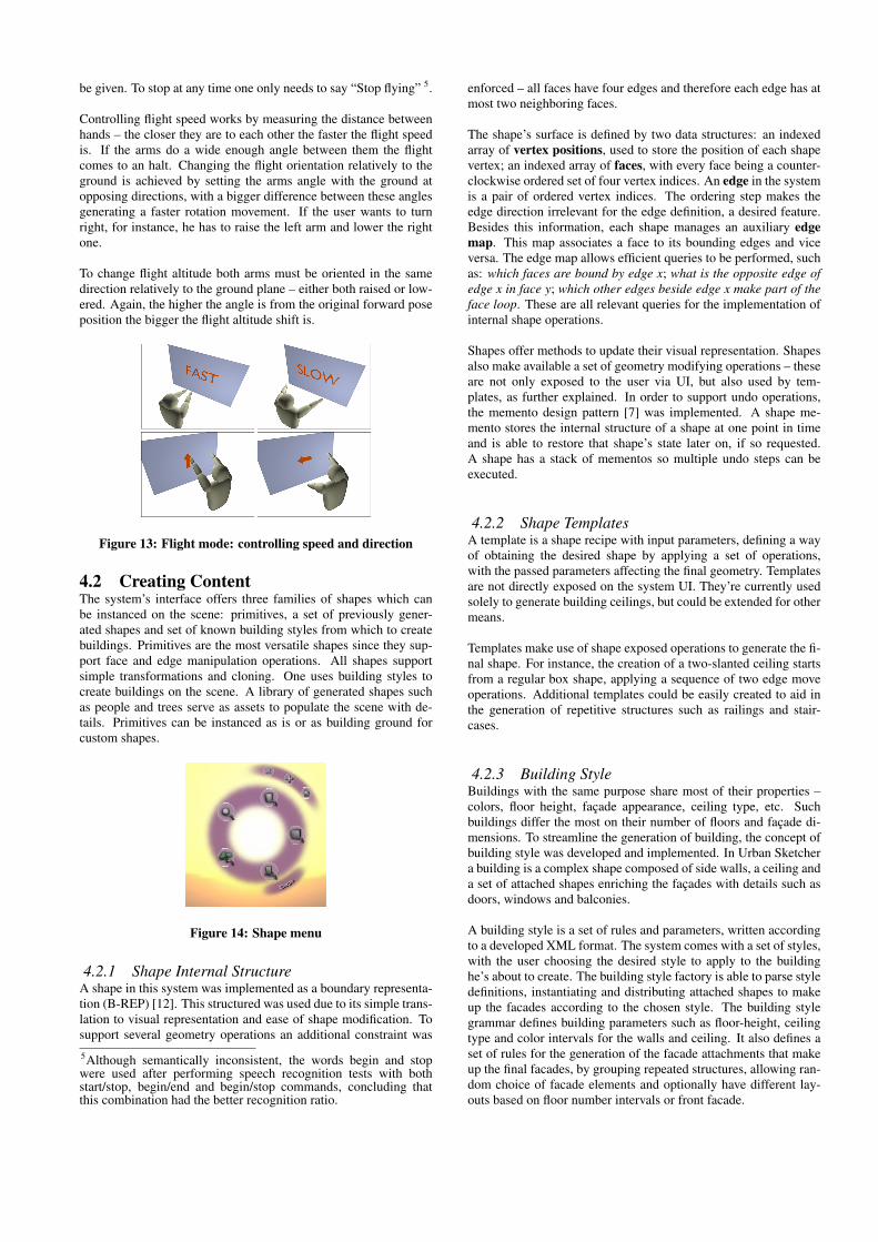
4.1.4 Multimodal Flight ModeThe Multimodal Flight Mode is an alternative navigation mode de-vised by the author to provide an alternative way of moving on theworld. This mode relies on arm gestures to control flight speed,rotation and altitude shift. These operations are smoothly appliedby continuous arm tracking and the application of a set of simplerules to identify the user’s purpose. This mode doesn’t rely on laserinput and can be enabled or disabled by speech commands.
To implement such mode the 3.6 Multimodal Input Interface wasused. Since it affects the point of view, this task can not be per-formed by several people simultaneously, therefore unlike most ofthe system this navigation mode has global states – the user mightbe either stationary of flying (see Fig.13).
The user starts interacting by having his arms extended toward thescreen. In order to begin flying the command “Begin flying” must
be given. To stop at any time one only needs to say “Stop flying” 5.
Controlling flight speed works by measuring the distance betweenhands – the closer they are to each other the faster the flight speedis. If the arms do a wide enough angle between them the flightcomes to an halt. Changing the flight orientation relatively to theground is achieved by setting the arms angle with the ground atopposing directions, with a bigger difference between these anglesgenerating a faster rotation movement. If the user wants to turnright, for instance, he has to raise the left arm and lower the rightone.
To change flight altitude both arms must be oriented in the samedirection relatively to the ground plane – either both raised or low-ered. Again, the higher the angle is from the original forward poseposition the bigger the flight altitude shift is.
Figure 13: Flight mode: controlling speed and direction
4.2 Creating ContentThe system’s interface offers three families of shapes which canbe instanced on the scene: primitives, a set of previously gener-ated shapes and set of known building styles from which to createbuildings. Primitives are the most versatile shapes since they sup-port face and edge manipulation operations. All shapes supportsimple transformations and cloning. One uses building styles tocreate buildings on the scene. A library of generated shapes suchas people and trees serve as assets to populate the scene with de-tails. Primitives can be instanced as is or as building ground forcustom shapes.
Figure 14: Shape menu
4.2.1 Shape Internal StructureA shape in this system was implemented as a boundary representa-tion (B-REP) [12]. This structured was used due to its simple trans-lation to visual representation and ease of shape modification. Tosupport several geometry operations an additional constraint was
5Although semantically inconsistent, the words begin and stopwere used after performing speech recognition tests with bothstart/stop, begin/end and begin/stop commands, concluding thatthis combination had the better recognition ratio.
enforced – all faces have four edges and therefore each edge has atmost two neighboring faces.
The shape’s surface is defined by two data structures: an indexedarray of vertex positions, used to store the position of each shapevertex; an indexed array of faces, with every face being a counter-clockwise ordered set of four vertex indices. An edge in the systemis a pair of ordered vertex indices. The ordering step makes theedge direction irrelevant for the edge definition, a desired feature.Besides this information, each shape manages an auxiliary edgemap. This map associates a face to its bounding edges and viceversa. The edge map allows efficient queries to be performed, suchas: which faces are bound by edge x; what is the opposite edge ofedge x in face y; which other edges beside edge x make part of theface loop. These are all relevant queries for the implementation ofinternal shape operations.
Shapes offer methods to update their visual representation. Shapesalso make available a set of geometry modifying operations – theseare not only exposed to the user via UI, but also used by tem-plates, as further explained. In order to support undo operations,the memento design pattern [7] was implemented. A shape me-mento stores the internal structure of a shape at one point in timeand is able to restore that shape’s state later on, if so requested.A shape has a stack of mementos so multiple undo steps can beexecuted.
4.2.2 Shape TemplatesA template is a shape recipe with input parameters, defining a wayof obtaining the desired shape by applying a set of operations,with the passed parameters affecting the final geometry. Templatesare not directly exposed on the system UI. They’re currently usedsolely to generate building ceilings, but could be extended for othermeans.
Templates make use of shape exposed operations to generate the fi-nal shape. For instance, the creation of a two-slanted ceiling startsfrom a regular box shape, applying a sequence of two edge moveoperations. Additional templates could be easily created to aid inthe generation of repetitive structures such as railings and stair-cases.
4.2.3 Building StyleBuildings with the same purpose share most of their properties –colors, floor height, façade appearance, ceiling type, etc. Suchbuildings differ the most on their number of floors and façade di-mensions. To streamline the generation of building, the concept ofbuilding style was developed and implemented. In Urban Sketchera building is a complex shape composed of side walls, a ceiling anda set of attached shapes enriching the façades with details such asdoors, windows and balconies.
A building style is a set of rules and parameters, written accordingto a developed XML format. The system comes with a set of styles,with the user choosing the desired style to apply to the buildinghe’s about to create. The building style factory is able to parse styledefinitions, instantiating and distributing attached shapes to makeup the facades according to the chosen style. The building stylegrammar defines building parameters such as floor-height, ceilingtype and color intervals for the walls and ceiling. It also defines aset of rules for the generation of the facade attachments that makeup the final facades, by grouping repeated structures, allowing ran-dom choice of facade elements and optionally have different lay-outs based on floor number intervals or front facade.
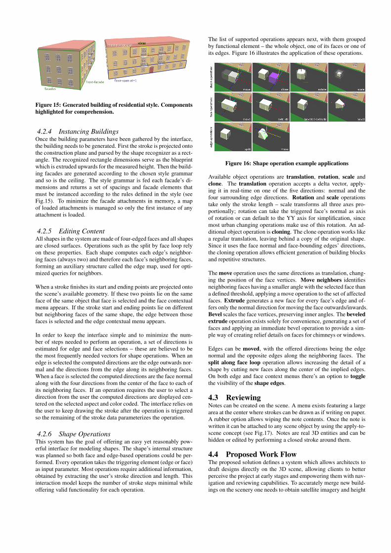
Figure 15: Generated building of residential style. Componentshighlighted for comprehension.
4.2.4 Instancing BuildingsOnce the building parameters have been gathered by the interface,the building needs to be generated. First the stroke is projected ontothe construction plane and parsed by the shape recognizer as a rect-angle. The recognized rectangle dimensions serve as the blueprintwhich is extruded upwards for the measured height. Then the build-ing facades are generated according to the chosen style grammarand so is the ceiling. The style grammar is fed each facade’s di-mensions and returns a set of spacings and facade elements thatmust be instanced according to the rules defined in the style (seeFig.15). To minimize the facade attachments in memory, a mapof loaded attachments is managed so only the first instance of anyattachment is loaded.
4.2.5 Editing ContentAll shapes in the system are made of four-edged faces and all shapesare closed surfaces. Operations such as the split by face loop relyon these properties. Each shape computes each edge’s neighbor-ing faces (always two) and therefore each face’s neighboring faces,forming an auxiliary structure called the edge map, used for opti-mized queries for neighbors.
When a stroke finishes its start and ending points are projected ontothe scene’s available geometry. If these two points lie on the sameface of the same object that face is selected and the face contextualmenu appears. If the stroke start and ending points lie on differentbut neighboring faces of the same shape, the edge between thosefaces is selected and the edge contextual menu appears.
In order to keep the interface simple and to minimize the num-ber of steps needed to perform an operation, a set of directions isestimated for edge and face selections – these are believed to bethe most frequently needed vectors for shape operations. When anedge is selected the computed directions are the edge outwards nor-mal and the directions from the edge along its neighboring faces.When a face is selected the computed directions are the face normalalong with the four directions from the center of the face to each ofits neighboring faces. If an operation requires the user to select adirection from the user the computed directions are displayed cen-tered on the selected aspect and color coded. The interface relies onthe user to keep drawing the stroke after the operation is triggeredso the remaining of the stroke data parameterizes the operation.
4.2.6 Shape OperationsThis system has the goal of offering an easy yet reasonably pow-erful interface for modeling shapes. The shape’s internal structurewas planned so both face and edge-based operations could be per-formed. Every operation takes the triggering element (edge or face)as input parameter. Most operations require additional information,obtained by extracting the user’s stroke direction and length. Thisinteraction model keeps the number of stroke steps minimal whileoffering valid functionality for each operation.
The list of supported operations appears next, with them groupedby functional element – the whole object, one of its faces or one ofits edges. Figure 16 illustrates the application of these operations.
Figure 16: Shape operation example applications
Available object operations are translation, rotation, scale andclone. The translation operation accepts a delta vector, apply-ing it in real-time on one of the five directions: normal and thefour surrounding edge directions. Rotation and scale operationstake only the stroke length – scale transforms all three axes pro-portionally; rotation can take the triggered face’s normal as axisof rotation or can default to the YY axis for simplification, sincemost urban changing operations make use of this rotation. An ad-ditional object operation is cloning. The clone operation works likea regular translation, leaving behind a copy of the original shape.Since it uses the face normal and face-bounding edges’ directions,the cloning operation allows efficient generation of building blocksand repetitive structures.
The move operation uses the same directions as translation, chang-ing the position of the face vertices. Move neighbors identifiesneighboring faces having a smaller angle with the selected face thana defined threshold, applying a move operation to the set of affectedfaces. Extrude generates a new face for every face’s edge and of-fers only the normal direction for moving the face outwards/inwards.Bevel scales the face vertices, preserving inner angles. The beveledextrude operation exists solely for convenience, generating a set offaces and applying an immediate bevel operation to provide a sim-ple way of creating relief details on faces for chimneys or windows.
Edges can be moved, with the offered directions being the edgenormal and the opposite edges along the neighboring faces. Thesplit along face loop operation allows increasing the detail of ashape by cutting new faces along the center of the implied edges.On both edge and face context menus there’s an option to togglethe visibility of the shape edges.
4.3 ReviewingNotes can be created on the scene. A menu exists featuring a largearea at the center where strokes can be drawn as if writing on paper.A rubber option allows wiping the note contents. Once the note iswritten it can be attached to any scene object by using the apply-to-scene concept (see Fig.17). Notes are real 3D entities and can behidden or edited by performing a closed stroke around them.
4.4 Proposed Work FlowThe proposed solution defines a system which allows architects todraft designs directly on the 3D scene, allowing clients to betterperceive the project at early stages and empowering them with nav-igation and reviewing capabilities. To accurately merge new build-ings on the scenery one needs to obtain satellite imagery and height
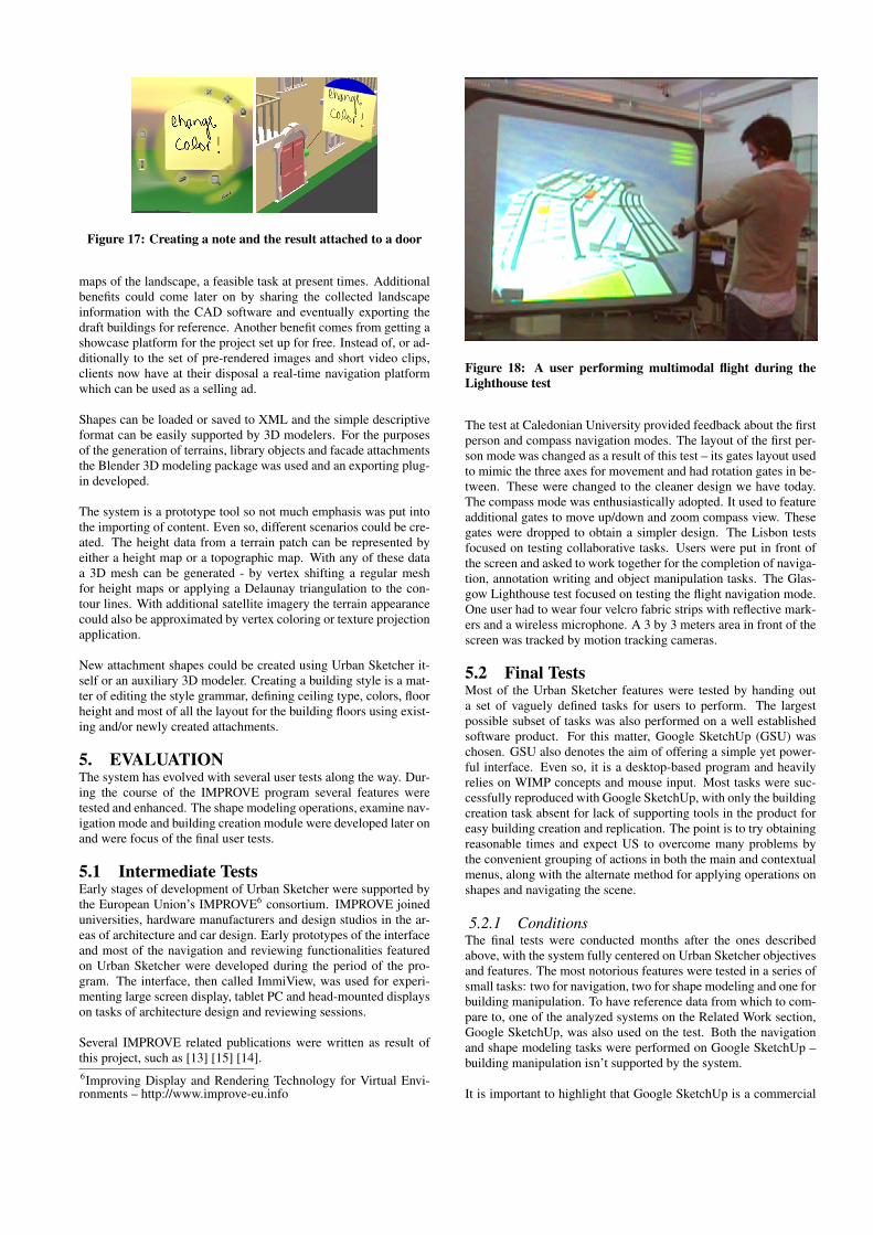
Figure 17: Creating a note and the result attached to a door
maps of the landscape, a feasible task at present times. Additionalbenefits could come later on by sharing the collected landscapeinformation with the CAD software and eventually exporting thedraft buildings for reference. Another benefit comes from getting ashowcase platform for the project set up for free. Instead of, or ad-ditionally to the set of pre-rendered images and short video clips,clients now have at their disposal a real-time navigation platformwhich can be used as a selling ad.
Shapes can be loaded or saved to XML and the simple descriptiveformat can be easily supported by 3D modelers. For the purposesof the generation of terrains, library objects and facade attachmentsthe Blender 3D modeling package was used and an exporting plug-in developed.
The system is a prototype tool so not much emphasis was put intothe importing of content. Even so, different scenarios could be cre-ated. The height data from a terrain patch can be represented byeither a height map or a topographic map. With any of these dataa 3D mesh can be generated - by vertex shifting a regular meshfor height maps or applying a Delaunay triangulation to the con-tour lines. With additional satellite imagery the terrain appearancecould also be approximated by vertex coloring or texture projectionapplication.
New attachment shapes could be created using Urban Sketcher it-self or an auxiliary 3D modeler. Creating a building style is a mat-ter of editing the style grammar, defining ceiling type, colors, floorheight and most of all the layout for the building floors using exist-ing and/or newly created attachments.
5. EVALUATIONThe system has evolved with several user tests along the way. Dur-ing the course of the IMPROVE program several features weretested and enhanced. The shape modeling operations, examine nav-igation mode and building creation module were developed later onand were focus of the final user tests.
5.1 Intermediate TestsEarly stages of development of Urban Sketcher were supported bythe European Union’s IMPROVE6 consortium. IMPROVE joineduniversities, hardware manufacturers and design studios in the ar-eas of architecture and car design. Early prototypes of the interfaceand most of the navigation and reviewing functionalities featuredon Urban Sketcher were developed during the period of the pro-gram. The interface, then called ImmiView, was used for experi-menting large screen display, tablet PC and head-mounted displayson tasks of architecture design and reviewing sessions.
Several IMPROVE related publications were written as result ofthis project, such as [13] [15] [14].6Improving Display and Rendering Technology for Virtual Envi-ronments – http://www.improve-eu.info
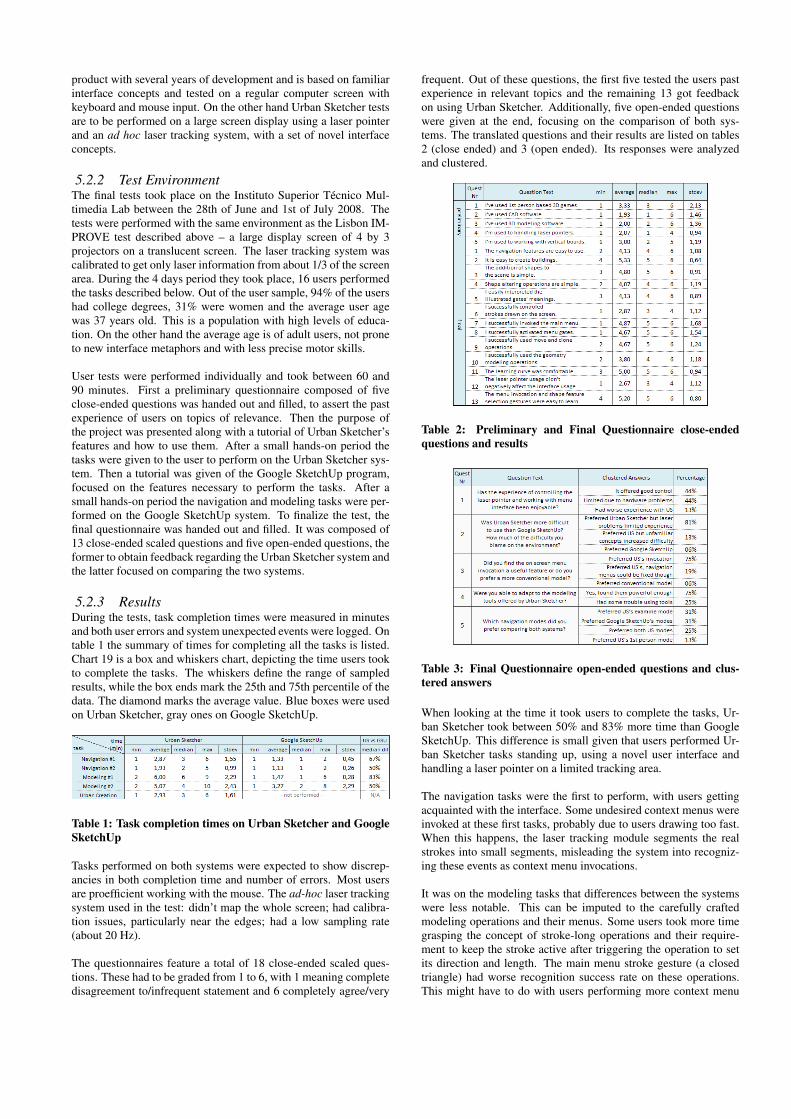
Figure 18: A user performing multimodal flight during theLighthouse test
The test at Caledonian University provided feedback about the firstperson and compass navigation modes. The layout of the first per-son mode was changed as a result of this test – its gates layout usedto mimic the three axes for movement and had rotation gates in be-tween. These were changed to the cleaner design we have today.The compass mode was enthusiastically adopted. It used to featureadditional gates to move up/down and zoom compass view. Thesegates were dropped to obtain a simpler design. The Lisbon testsfocused on testing collaborative tasks. Users were put in front ofthe screen and asked to work together for the completion of naviga-tion, annotation writing and object manipulation tasks. The Glas-gow Lighthouse test focused on testing the flight navigation mode.One user had to wear four velcro fabric strips with reflective mark-ers and a wireless microphone. A 3 by 3 meters area in front of thescreen was tracked by motion tracking cameras.
5.2 Final TestsMost of the Urban Sketcher features were tested by handing outa set of vaguely defined tasks for users to perform. The largestpossible subset of tasks was also performed on a well establishedsoftware product. For this matter, Google SketchUp (GSU) waschosen. GSU also denotes the aim of offering a simple yet power-ful interface. Even so, it is a desktop-based program and heavilyrelies on WIMP concepts and mouse input. Most tasks were suc-cessfully reproduced with Google SketchUp, with only the buildingcreation task absent for lack of supporting tools in the product foreasy building creation and replication. The point is to try obtainingreasonable times and expect US to overcome many problems bythe convenient grouping of actions in both the main and contextualmenus, along with the alternate method for applying operations onshapes and navigating the scene.
5.2.1 ConditionsThe final tests were conducted months after the ones describedabove, with the system fully centered on Urban Sketcher objectivesand features. The most notorious features were tested in a series ofsmall tasks: two for navigation, two for shape modeling and one forbuilding manipulation. To have reference data from which to com-pare to, one of the analyzed systems on the Related Work section,Google SketchUp, was also used on the test. Both the navigationand shape modeling tasks were performed on Google SketchUp –building manipulation isn’t supported by the system.
It is important to highlight that Google SketchUp is a commercial
product with several years of development and is based on familiarinterface concepts and tested on a regular computer screen withkeyboard and mouse input. On the other hand Urban Sketcher testsare to be performed on a large screen display using a laser pointerand an ad hoc laser tracking system, with a set of novel interfaceconcepts.
5.2.2 Test EnvironmentThe final tests took place on the Instituto Superior Técnico Mul-timedia Lab between the 28th of June and 1st of July 2008. Thetests were performed with the same environment as the Lisbon IM-PROVE test described above – a large display screen of 4 by 3projectors on a translucent screen. The laser tracking system wascalibrated to get only laser information from about 1/3 of the screenarea. During the 4 days period they took place, 16 users performedthe tasks described below. Out of the user sample, 94% of the usershad college degrees, 31% were women and the average user agewas 37 years old. This is a population with high levels of educa-tion. On the other hand the average age is of adult users, not proneto new interface metaphors and with less precise motor skills.
User tests were performed individually and took between 60 and90 minutes. First a preliminary questionnaire composed of fiveclose-ended questions was handed out and filled, to assert the pastexperience of users on topics of relevance. Then the purpose ofthe project was presented along with a tutorial of Urban Sketcher’sfeatures and how to use them. After a small hands-on period thetasks were given to the user to perform on the Urban Sketcher sys-tem. Then a tutorial was given of the Google SketchUp program,focused on the features necessary to perform the tasks. After asmall hands-on period the navigation and modeling tasks were per-formed on the Google SketchUp system. To finalize the test, thefinal questionnaire was handed out and filled. It was composed of13 close-ended scaled questions and five open-ended questions, theformer to obtain feedback regarding the Urban Sketcher system andthe latter focused on comparing the two systems.
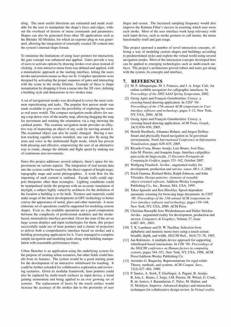
5.2.3 ResultsDuring the tests, task completion times were measured in minutesand both user errors and system unexpected events were logged. Ontable 1 the summary of times for completing all the tasks is listed.Chart 19 is a box and whiskers chart, depicting the time users tookto complete the tasks. The whiskers define the range of sampledresults, while the box ends mark the 25th and 75th percentile of thedata. The diamond marks the average value. Blue boxes were usedon Urban Sketcher, gray ones on Google SketchUp.
Table 1: Task completion times on Urban Sketcher and GoogleSketchUp
Tasks performed on both systems were expected to show discrep-ancies in both completion time and number of errors. Most usersare proefficient working with the mouse. The ad-hoc laser trackingsystem used in the test: didn’t map the whole screen; had calibra-tion issues, particularly near the edges; had a low sampling rate(about 20 Hz).
The questionnaires feature a total of 18 close-ended scaled ques-tions. These had to be graded from 1 to 6, with 1 meaning completedisagreement to/infrequent statement and 6 completely agree/very
frequent. Out of these questions, the first five tested the users pastexperience in relevant topics and the remaining 13 got feedbackon using Urban Sketcher. Additionally, five open-ended questionswere given at the end, focusing on the comparison of both sys-tems. The translated questions and their results are listed on tables2 (close ended) and 3 (open ended). Its responses were analyzedand clustered.
Table 2: Preliminary and Final Questionnaire close-endedquestions and results
Table 3: Final Questionnaire open-ended questions and clus-tered answers
When looking at the time it took users to complete the tasks, Ur-ban Sketcher took between 50% and 83% more time than GoogleSketchUp. This difference is small given that users performed Ur-ban Sketcher tasks standing up, using a novel user interface andhandling a laser pointer on a limited tracking area.
The navigation tasks were the first to perform, with users gettingacquainted with the interface. Some undesired context menus wereinvoked at these first tasks, probably due to users drawing too fast.When this happens, the laser tracking module segments the realstrokes into small segments, misleading the system into recogniz-ing these events as context menu invocations.
It was on the modeling tasks that differences between the systemswere less notable. This can be imputed to the carefully craftedmodeling operations and their menus. Some users took more timegrasping the concept of stroke-long operations and their require-ment to keep the stroke active after triggering the operation to setits direction and length. The main menu stroke gesture (a closedtriangle) had worse recognition success rate on these operations.This might have to do with users performing more context menu
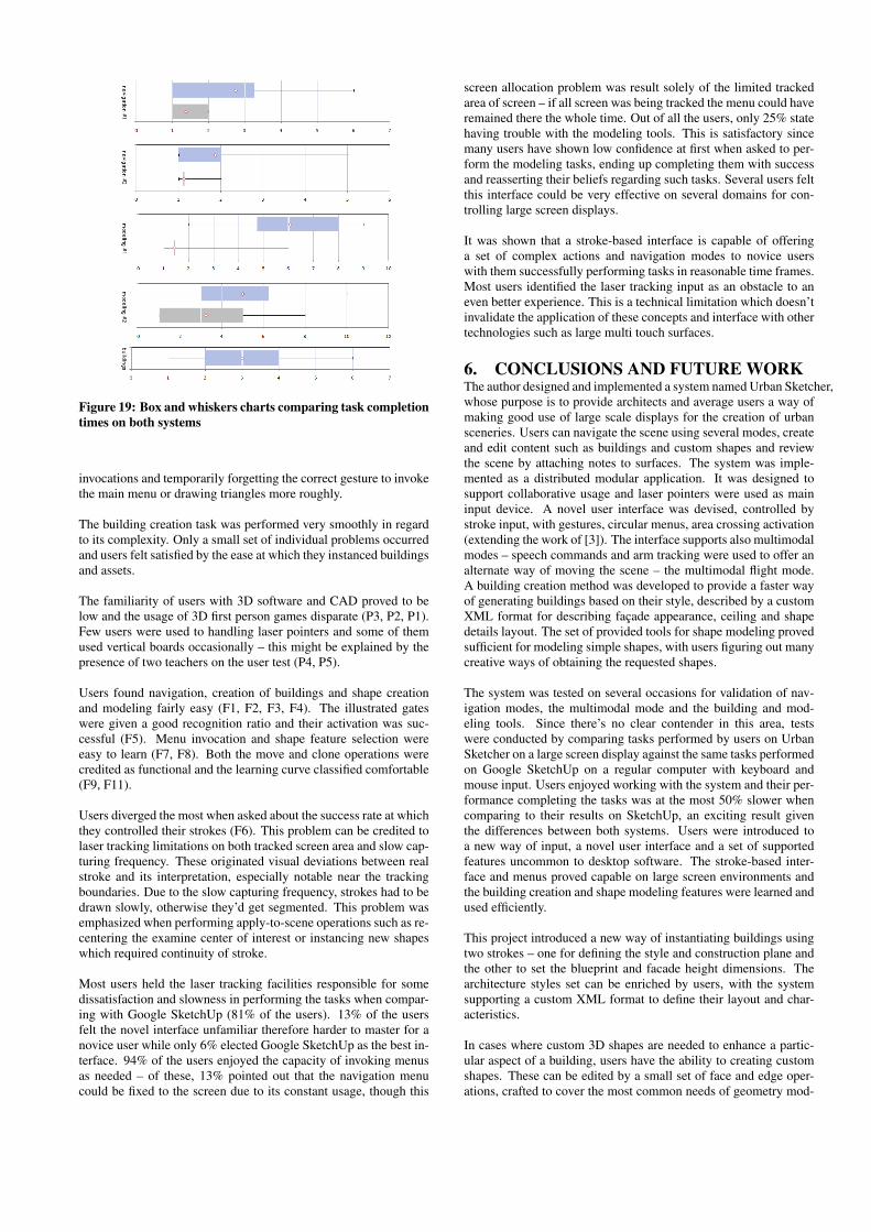
Figure 19: Box and whiskers charts comparing task completiontimes on both systems
invocations and temporarily forgetting the correct gesture to invokethe main menu or drawing triangles more roughly.
The building creation task was performed very smoothly in regardto its complexity. Only a small set of individual problems occurredand users felt satisfied by the ease at which they instanced buildingsand assets.
The familiarity of users with 3D software and CAD proved to below and the usage of 3D first person games disparate (P3, P2, P1).Few users were used to handling laser pointers and some of themused vertical boards occasionally – this might be explained by thepresence of two teachers on the user test (P4, P5).
Users found navigation, creation of buildings and shape creationand modeling fairly easy (F1, F2, F3, F4). The illustrated gateswere given a good recognition ratio and their activation was suc-cessful (F5). Menu invocation and shape feature selection wereeasy to learn (F7, F8). Both the move and clone operations werecredited as functional and the learning curve classified comfortable(F9, F11).
Users diverged the most when asked about the success rate at whichthey controlled their strokes (F6). This problem can be credited tolaser tracking limitations on both tracked screen area and slow cap-turing frequency. These originated visual deviations between realstroke and its interpretation, especially notable near the trackingboundaries. Due to the slow capturing frequency, strokes had to bedrawn slowly, otherwise they’d get segmented. This problem wasemphasized when performing apply-to-scene operations such as re-centering the examine center of interest or instancing new shapeswhich required continuity of stroke.
Most users held the laser tracking facilities responsible for somedissatisfaction and slowness in performing the tasks when compar-ing with Google SketchUp (81% of the users). 13% of the usersfelt the novel interface unfamiliar therefore harder to master for anovice user while only 6% elected Google SketchUp as the best in-terface. 94% of the users enjoyed the capacity of invoking menusas needed – of these, 13% pointed out that the navigation menucould be fixed to the screen due to its constant usage, though this
screen allocation problem was result solely of the limited trackedarea of screen – if all screen was being tracked the menu could haveremained there the whole time. Out of all the users, only 25% statehaving trouble with the modeling tools. This is satisfactory sincemany users have shown low confidence at first when asked to per-form the modeling tasks, ending up completing them with successand reasserting their beliefs regarding such tasks. Several users feltthis interface could be very effective on several domains for con-trolling large screen displays.
It was shown that a stroke-based interface is capable of offeringa set of complex actions and navigation modes to novice userswith them successfully performing tasks in reasonable time frames.Most users identified the laser tracking input as an obstacle to aneven better experience. This is a technical limitation which doesn’tinvalidate the application of these concepts and interface with othertechnologies such as large multi touch surfaces.
6. CONCLUSIONS AND FUTURE WORKThe author designed and implemented a system named Urban Sketcher,whose purpose is to provide architects and average users a way ofmaking good use of large scale displays for the creation of urbansceneries. Users can navigate the scene using several modes, createand edit content such as buildings and custom shapes and reviewthe scene by attaching notes to surfaces. The system was imple-mented as a distributed modular application. It was designed tosupport collaborative usage and laser pointers were used as maininput device. A novel user interface was devised, controlled bystroke input, with gestures, circular menus, area crossing activation(extending the work of [3]). The interface supports also multimodalmodes – speech commands and arm tracking were used to offer analternate way of moving the scene – the multimodal flight mode.A building creation method was developed to provide a faster wayof generating buildings based on their style, described by a customXML format for describing façade appearance, ceiling and shapedetails layout. The set of provided tools for shape modeling provedsufficient for modeling simple shapes, with users figuring out manycreative ways of obtaining the requested shapes.
The system was tested on several occasions for validation of nav-igation modes, the multimodal mode and the building and mod-eling tools. Since there’s no clear contender in this area, testswere conducted by comparing tasks performed by users on UrbanSketcher on a large screen display against the same tasks performedon Google SketchUp on a regular computer with keyboard andmouse input. Users enjoyed working with the system and their per-formance completing the tasks was at the most 50% slower whencomparing to their results on SketchUp, an exciting result giventhe differences between both systems. Users were introduced toa new way of input, a novel user interface and a set of supportedfeatures uncommon to desktop software. The stroke-based inter-face and menus proved capable on large screen environments andthe building creation and shape modeling features were learned andused efficiently.
This project introduced a new way of instantiating buildings usingtwo strokes – one for defining the style and construction plane andthe other to set the blueprint and facade height dimensions. Thearchitecture styles set can be enriched by users, with the systemsupporting a custom XML format to define their layout and char-acteristics.
In cases where custom 3D shapes are needed to enhance a partic-ular aspect of a building, users have the ability to creating customshapes. These can be edited by a small set of face and edge oper-ations, crafted to cover the most common needs of geometry mod-
eling. The most useful directions are estimated and made avail-able for the user to manipulate the shape’s faces and edges, with-out the overhead of dozens of menu commands and parameters.Shapes can also be generated from other 3D applications such asthe Blender 3D Modeler, for which an exporter plug-in was gener-ated, allowing the integration of externally created 3D content intothe system’s internal shape format.
To minimize the limitations of using laser pointers for interaction,the gate concept was enhanced and applied. Gates provide a wayof users to activate options by drawing strokes over areas instead ofclicking. A non-intrusive menu form was defined and applied, witha minimalistic approach at the starting interface, letting the usersinvoke and position menus as they see fit. Complex operations weredesigned by activating the proper sequence of gates and interactingwith the scene in the stroke lifetime. Example of these is shapeinstantiation by dropping it from a menu into the 3D view; defininga building style and dimensions in two strokes time.
A set of navigational modes was developed to cover the most com-mon repositioning and tasks. The popular first person mode wasmade available to give users the possibility of exploring the sceneas real users would. The compass navigation mode allows for see-ing a top-down view of the nearby map, allowing dragging the mapfor movement and rotating the orientation via a ring showing thecardinal points. The examine navigation mode provides an effec-tive way of inspecting an object of any scale by moving around it.The examined object can also be easily changed. Having a mo-tion tracking capable system installed, one can also fly using thearms and voice in the multimodal flight mode, which has provenboth pleasing and effective, empowering the user of an alternativeway to rotate, change the altitude and flight speed by making useof continuous arm movements.
Since this project addresses several subjects, there’s space for im-provement on various aspects. The integration of real terrain datainto the system could be eased by the direct support of height maps,topography maps and aerial photographies. A work flow for theimporting of such content is outlined. Facade walls could sup-port blueprints other than rectangles. Lighting conditions couldbe manipulated inside the program with an accurate simulation ofdaylight, a subject highly valued by architects for the definition ofthe location a building is to be built. Textures and materials couldmake usage of the latest developments in GPU technology to betterconvey the appearance of metal, glass and other materials. A moreelaborate set of operations could be supported for modeling customshapes. Even so, the available operations are a good compromisebetween the complexity of professional modelers and the stroke-based, minimalistic interface provided. Given the state of the art onlarge screen displays and input technologies for them, this projectsuccessfully made use of laser pointers and a cluster of projectorsto deliver both a comprehensive interface based on strokes and abuilding prototyping application for it. Users managed to completesimple navigation and modeling tasks along with building manipu-lation with reasonable performance times.
Urban Sketcher is an application using the underlying system forthe purpose of creating urban scenarios, but other fields could ben-efit from its features. The system would be a good starting pointfor the development of an interactive whiteboard for teaching. Itcould be further extended for collaborative exploration and review-ing scenarios. Given its modular framework, laser pointers couldalso be replaced by multi-touch surfaces as input device, a trendgaining momentum and being applied to an ever growing set ofsystems. The replacement of lasers by the touch surface wouldincrease the accuracy of the strokes due to the proximity of user
finger and screen. The increased sampling frequency would alsoimprove the Kalman Filter’s success in asserting which user ownseach stroke. Most of the user interface work keep relevancy withsuch input device, such as stroke gestures to call menus, the menufunctionality itself and gate usage.
This project spawned a number of novel interaction concepts, of-fering a way of modeling custom shapes and buildings accordingto predetermined styles and explore the virtual world using severalnavigation modes. Most of the interaction concepts developed herecan be applied to emerging technologies such as multi-touch sur-faces. The project’s architecture proved robust and users got alongwith the system, its concepts and interface.
7. REFERENCES[1] M. P. Albuquerque, M. J. Fonseca, and J. A. Jorge. Cali: An
online scribble recognizer for calligraphic interfaces. InProceedings of the 2002 AAAI Spring Symposium, 2002.
[2] Georg Apitz and François Guimbretière. Crossy: acrossing-based drawing application. In UIST ’04:Proceedings of the 17th annual ACM symposium on Userinterface software and technology, pages 3–12, New York,NY, USA, 2004. ACM.
[3] Georg Apitz and François Guimbretière. Crossy: acrossing-based drawing application. ACM Trans. Graph.,24(3):930–930, 2005.
[4] Henrik Buchholz, Johannes Bohnet, and Jurgen Dollner.Smart and physically-based navigation in 3d geovirtualenvironments. Ninth International Conference in InformationVisualisation, pages 629–635, 2005.
[5] Ricardo Costa, Bruno Araújo, Luis Bruno, José Dias,João M. Pereira, and Joaquim Jorge. Interface caligráficapara ecrãs de larga escala. 15 Encontro Português deComputação Gráfica, pages 153–162, October 2007.
[6] Wolfgang Friedrich. Arvika - augmented reality fordevelopment, production and service. ismar, 00:1–3, 2002.
[7] Erich Gamma, Richard Helm, Ralph Johnson, and JohnVlissides. Design patterns: elements of reusableobject-oriented software. Addison-Wesley LongmanPublishing Co., Inc., Boston, MA, USA, 1995.
[8] Takeo Igarashi and Ken Hinckley. Speed-dependentautomatic zooming for browsing large documents. In UIST’00: Proceedings of the 13th annual ACM symposium onUser interface software and technology, pages 139–148,New York, NY, USA, 2000. ACM Press.
[9] Christian Knoepfle Jens Weidenhausen and Didier Stricker.Arvika - augmented reality for development, production andservice. Computers & Graphics, Volume 27, Issue6:887–891, 2003.
[10] T. K. Landauer and D. W. Nachbar. Selection fromalphabetic and numeric menu trees using a touch screen:breadth, depth, and width. SIGCHI Bull., 16(4):73–78, 1985.
[11] Jun Rekimoto. A multiple device approach for supportingwhiteboard-based interactions. In CHI ’98: Proceedings ofthe SIGCHI conference on Human factors in computingsystems, pages 344–351, New York, NY, USA, 1998. ACMPress/Addison-Wesley Publishing Co.
[12] Aristides G. Requicha. Representations for rigid solids:Theory, methods, and systems. ACM Comput. Surv.,12(4):437–464, 1980.
[13] P. Santos, A. Stork, T. Gierlinger, A. Pagani, B. Araújo,R. Jota, L. Bruno, J. Jorge, J.M. Pereira, M. Witzel, G. Conti,R. de Amicis, I. Barandarian, C. Paloc, M. Hafner, andD. McIntyre. Improve: Advanced displays and interactiontechniques for collaborative design review. In Virtual reality.

Second international conference, ICVR 2007, pages376–385, 2007.
[14] P. Santos, A. Stork, T. Gierlinger, A. Pagani, B. Araújo,R. Jota, L. Bruno, J. Jorge, J.M. Pereira, M. Witzel, G. Conti,R. de Amicis, I. Barandarian, C. Paloc, M. Hafner, andD. McIntyre. Improve: Designing effective interaction forvirtual and mixed reality environments. In Human-computerinteraction. 12th international conference, HCI International2007. Vol.2: Interaction platforms and techniques, pages689–699, 2007.
[15] P. Santos, A. Stork, T. Gierlinger, A. Pagani, B. Araújo,R. Jota, L. Bruno, J. Jorge, J.M. Pereira, M. Witzel, G. Conti,R. de Amicis, I. Barandarian, C. Paloc, O. Machui, J.M.Jiménez, G. Bodammer, and D. McIntyre. Improve:Collaborative design review in mobile mixed reality. InVirtual reality. Second international conference, ICVR 2007,pages 543–553, 2007.
[16] Edward Tse, Chia Shen, Saul Greenberg, and CliftonForlines. Enabling interaction with single user applicationsthrough speech and gestures on a multi-user tabletop. In AVI’06: Proceedings of the working conference on Advancedvisual interfaces, pages 336–343, New York, NY, USA,2006. ACM Press.