uriglow transilluminating ureteric...
TRANSCRIPT

Revision 17 Author N.J.Tyrrell Product Manager, Research & Development
Published 24/07/18 Signed
ZDOCK298 Rev.17 24/07/18 Copyright© 1993-2018
URIGLOW® Transilluminating Ureteric Stents
Rocket® Users Guide
2 ZDOCK298 Rev.16 23/03/18 Copyright© 1993-2018
Contents
1. Introduction: ................................................................................................................................................. 3
2. The Problem: ................................................................................................................................................. 4
3. The Solution: ................................................................................................................................................. 5
4. Product Description: .................................................................................................................................... 6 4.1 URIGLOW® Stents: .................................................................................................................................................... 6 4.2 Construction:................................................................................................................................................................... 6 4.3 Specifications: ................................................................................................................................................................. 6 4.4 Fibre Optic Transmission: ........................................................................................................................................... 6
5. URIGLOW® Light Guide Coupler R57411: ................................................................................................. 7 5.1 Light Guide Connection: ................................................................................................................................................. 7
6. Light Sources: .............................................................................................................................................. 7
7. The Procedure: ............................................................................................................................................. 8 7.1 Unpacking stents and loading the cystoscope: ........................................................................................................... 8 7.2 Cystoscopy and ureteric cannulation: ......................................................................................................................... 9 7.3 Removal of the cystoscope and securing the URIGLOW®: ....................................................................................... 10
8. Using the URIGLOW® Light Guide Coupler: ........................................................................................... 11 8.2 Mounting the Light Guide Coupler using the URIGLOW® LGC Bracket ................................................................... 11 8.4 Attaching the stents to the URIGLOW® Light Guide Coupler: .................................................................................. 14
9. Ureteric identification - in laparoscopy and open surgery: ................................................................... 15 9.1 Laparoscopic Technique – Use of Shade: ................................................................................................................ 15
9.2 URIGLOW® Removal: .............................................................................................................................................. 15
10. Light Guide Coupler – Cleaning & Sterilisation ...................................................................................... 16
11. Reference: ................................................................................................................................................... 17
12. Rocket Medical Offices: ............................................................................................................................. 18
Contents

3 ZDOCK298 Rev.16 23/03/18 Copyright© 1993-2018
1. Introduction: Recent advances in laparoscopic techniques have challenged the established surgical practices of many surgeons. However, every surgical procedure carries with it some risk and even in the most experienced hands a patient may be inadvertently injured during the surgical procedure.
Any device which is solely designed to prevent inadvertent injury and reduce risk to the patient becomes as valuable to the surgeon as the most elaborate surgical instrument.
"....the frequency of damage to the descending ureter as complication of abdominal hysterectomy has been as high as 1.5%. Complications are more likely if the patient has undergone previous surgery, if the anatomy is distorted or in the presence of gross pelvic adhesions."
DalyJ.W. & Higgins K.A. 'Injury to the ureter during gynaecological surgery'. Surg Gynaecol Obstet. 167 19-22.
" ......a case of a laser laparoscopic dissection of the pelvic sidewall in a patient with very severe endometriosis where the ovaries were completely bound down with dense adhesions on top of the ureter.......it was very difficult to be absolutely sure that we were removing ovarian remnants without damaging the ureter."
Sutton C.J. Personal communication to the author. Sept '92.
"....the morbidity and financial cost of ureteric injury are such that any reduction in the occurrence of this complication must be welcomed."
Phipps J.H. & Tyrrell N.J. 'Transilluminating ureteric stents for preventing operative ureteric damage.' Brit J. Obstet & Gynaecol Jan 1992. Vol 99 pp. 81-84.
glow glo, v.i. to emit a steady light - n a luminous appearance.
light¹ lit, n. the agency by which objects are rendered visible: electromagnetic radiation capable of producing visual sensation: that from which it proceeds, as the sun, a lamp,: a high degree of illumination: day: a gleam or shining from a bright source:
prevent pre-vent', v.t. to precede (obs): to be, go or act earlier than (obs): to go faster than (obs): to anticipate, forestall (obs): to satisfy in advance (obs): to balk: to preclude: to stop, keep or hinder effectually: to keep from coming to pass. Chambers Dictionary. 1983.
Introduction
4 ZDOCK298 Rev.16 23/03/18 Copyright© 1993-2018
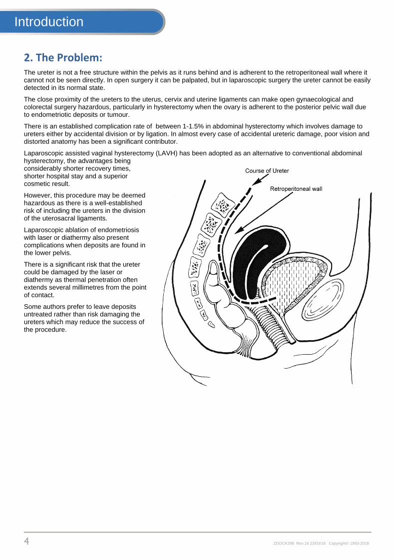
2. The Problem: The ureter is not a free structure within the pelvis as it runs behind and is adherent to the retroperitoneal wall where it cannot not be seen directly. In open surgery it can be palpated, but in laparoscopic surgery the ureter cannot be easily detected in its normal state.
The close proximity of the ureters to the uterus, cervix and uterine ligaments can make open gynaecological and colorectal surgery hazardous, particularly in hysterectomy when the ovary is adherent to the posterior pelvic wall due to endometriotic deposits or tumour.
There is an established complication rate of between 1-1.5% in abdominal hysterectomy which involves damage to ureters either by accidental division or by ligation. In almost every case of accidental ureteric damage, poor vision and distorted anatomy has been a significant contributor.
Laparoscopic assisted vaginal hysterectomy (LAVH) has been adopted as an alternative to conventional abdominal hysterectomy, the advantages being considerably shorter recovery times, shorter hospital stay and a superior cosmetic result.
However, this procedure may be deemed hazardous as there is a well-established risk of including the ureters in the division of the uterosacral ligaments.
Laparoscopic ablation of endometriosis with laser or diathermy also present complications when deposits are found in the lower pelvis.
There is a significant risk that the ureter could be damaged by the laser or diathermy as thermal penetration often extends several millimetres from the point of contact.
Some authors prefer to leave deposits untreated rather than risk damaging the ureters which may reduce the success of the procedure.
Introduction
5 ZDOCK298 Rev.16 23/03/18 Copyright© 1993-2018
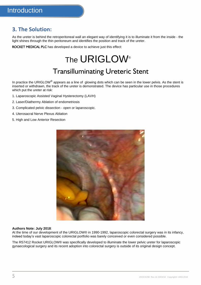
3. The Solution: As the ureter is behind the retroperitoneal wall an elegant way of identifying it is to illuminate it from the inside - the light shines through the thin peritoneum and identifies the position and track of the ureter.
ROCKET MEDICAL PLC has developed a device to achieve just this effect:
The URIGLOW
Transilluminating Ureteric Stent
In practice the URIGLOW® appears as a line of glowing dots which can be seen in the lower pelvis. As the stent is inserted or withdrawn, the track of the ureter is demonstrated. The device has particular use in those procedures which put the ureter at risk:
1. Laparoscopic Assisted Vaginal Hysterectomy (LAVH)
2. Laser/Diathermy Ablation of endometriosis
3. Complicated pelvic dissection - open or laparoscopic.
4. Uterosacral Nerve Plexus Ablation
5. High and Low Anterior Resection
Authors Note: July 2018: At the time of our development of the URIGLOW® in 1990-1992, laparoscopic colorectal surgery was in its infancy, indeed today’s vast laparoscopic colorectal portfolio was barely conceived or even considered possible.
The R57412 Rocket URIGLOW® was specifically developed to illuminate the lower pelvic ureter for laparoscopic gynaecological surgery and its recent adoption into colorectal surgery is outside of its original design concept.
Introduction

6 ZDOCK298 Rev.16 23/03/18 Copyright© 1993-2018
4. Product Description:
4.1 URIGLOW® Stents:
The URIGLOW® is a fibre optic ureteric stent designed to connect to a high intensity laparoscopic light source. See Section 6 for guidance on light sources
It is inserted into the ureter through a standard operating cystoscope as for any conventional ureteric catheter. The stent has universal markings to assist in correct placement.
The distal tip is specially prepared to emit light from 6 points 1cm apart which allows easy identification of the position and track of the ureter. The catheter can be inserted and withdrawn during the operative procedure to demonstrate different portions of the ureteric tract.
4.2 Construction:
The URIGLOW® is an acrylic single fibre bundle 1m long covered in a medical grade PVC coating.
The ends of the stent are sealed with medical grade epoxy resin, the distal end is then domed whilst the proximal end is cut and polished.
Markings are conventional 1cm graduations commencing 75mm from the tip
The 6 glow points are produced by etching the refractive coating to release light from the fibre.
4.3 Specifications:
Optical Fibre: 1.9mm (6FG) OD x 100cm Radio-opaque marker line. Active tip: 6 x 1cm high intensity emission points. 1st point 15mm from distal domed tip.
Marker positions from the distal tip :
1st single blue marker: 75mm
2nd single blue marker: 85mm
3rd single blue marker: 95mm
4th single blue marker: 105mm
5th double blue marker: 120mm
Mid-point of RED marker: 175mm
Mid-point of wide BLUE marker: 285mm
4.4 Fibre Optic Transmission:
All fibre-optic cable systems rely on a property of light known as 'Total Internal Reflection'. When light passes from one medium to another which is optically less dense e.g. from glass to air, the ray is bent away from the normal.
If the incident ray meets the surface at such an angle that the refracted ray is bent away at an angle of more than 90°, then the light cannot emerge at all and is totally internally reflected. In practice this is commonly achieved by applying a vacuum coating to an acrylic fibre.
Technical
7 ZDOCK298 Rev.16 23/03/18 Copyright© 1993-2018
5. URIGLOW® Light Guide Coupler R57411:
5.1 Light Guide Connection:
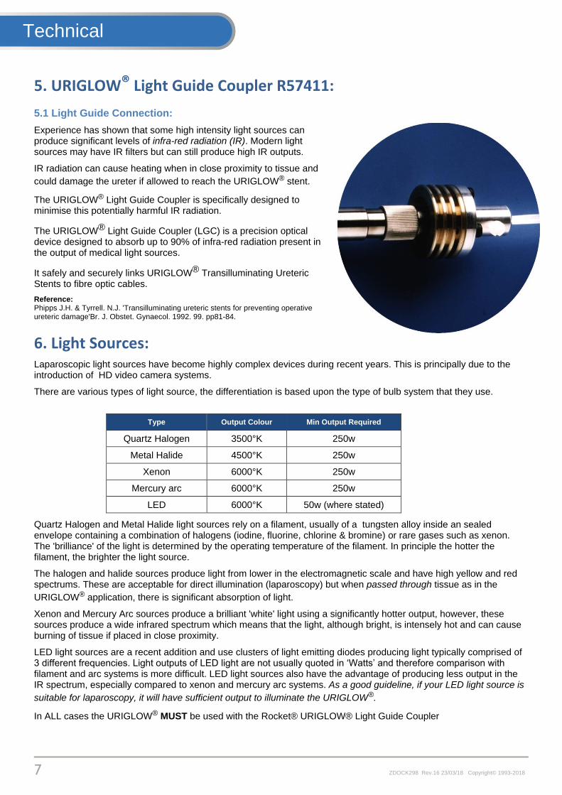
Experience has shown that some high intensity light sources can produce significant levels of infra-red radiation (IR). Modern light sources may have IR filters but can still produce high IR outputs.
IR radiation can cause heating when in close proximity to tissue and
could damage the ureter if allowed to reach the URIGLOW® stent.
The URIGLOW® Light Guide Coupler is specifically designed to minimise this potentially harmful IR radiation.
The URIGLOW® Light Guide Coupler (LGC) is a precision optical device designed to absorb up to 90% of infra-red radiation present in the output of medical light sources.
It safely and securely links URIGLOW® Transilluminating Ureteric Stents to fibre optic cables.
Reference: Phipps J.H. & Tyrrell. N.J. 'Transilluminating ureteric stents for preventing operative ureteric damage'Br. J. Obstet. Gynaecol. 1992. 99. pp81-84.
6. Light Sources: Laparoscopic light sources have become highly complex devices during recent years. This is principally due to the introduction of HD video camera systems.
There are various types of light source, the differentiation is based upon the type of bulb system that they use.
Type Output Colour Min Output Required
Quartz Halogen 3500°K 250w
Metal Halide 4500°K 250w
Xenon 6000°K 250w
Mercury arc 6000°K 250w
LED 6000°K 50w (where stated)
Quartz Halogen and Metal Halide light sources rely on a filament, usually of a tungsten alloy inside an sealed envelope containing a combination of halogens (iodine, fluorine, chlorine & bromine) or rare gases such as xenon. The 'brilliance' of the light is determined by the operating temperature of the filament. In principle the hotter the filament, the brighter the light source.
The halogen and halide sources produce light from lower in the electromagnetic scale and have high yellow and red spectrums. These are acceptable for direct illumination (laparoscopy) but when passed through tissue as in the
URIGLOW® application, there is significant absorption of light.
Xenon and Mercury Arc sources produce a brilliant 'white' light using a significantly hotter output, however, these sources produce a wide infrared spectrum which means that the light, although bright, is intensely hot and can cause burning of tissue if placed in close proximity.
LED light sources are a recent addition and use clusters of light emitting diodes producing light typically comprised of 3 different frequencies. Light outputs of LED light are not usually quoted in ‘Watts’ and therefore comparison with filament and arc systems is more difficult. LED light sources also have the advantage of producing less output in the IR spectrum, especially compared to xenon and mercury arc systems. As a good guideline, if your LED light source is
suitable for laparoscopy, it will have sufficient output to illuminate the URIGLOW®.
In ALL cases the URIGLOW® MUST be used with the Rocket® URIGLOW® Light Guide Coupler
Technical
8 ZDOCK298 Rev.16 23/03/18 Copyright© 1993-2018
7. The Procedure: The procedure to place and use the URIGLOW®can be divided into the following sections:
(a) Unpacking the stents and loading the cystoscope.
(b) Cystoscopy and ureteric cannulation
(c) Removal of the cystoscope and securing the URIGLOW®
(e) Light source connections
(f) Ureteric identification - in laparoscopy and open surgery.
(g) URIGLOW® removal.
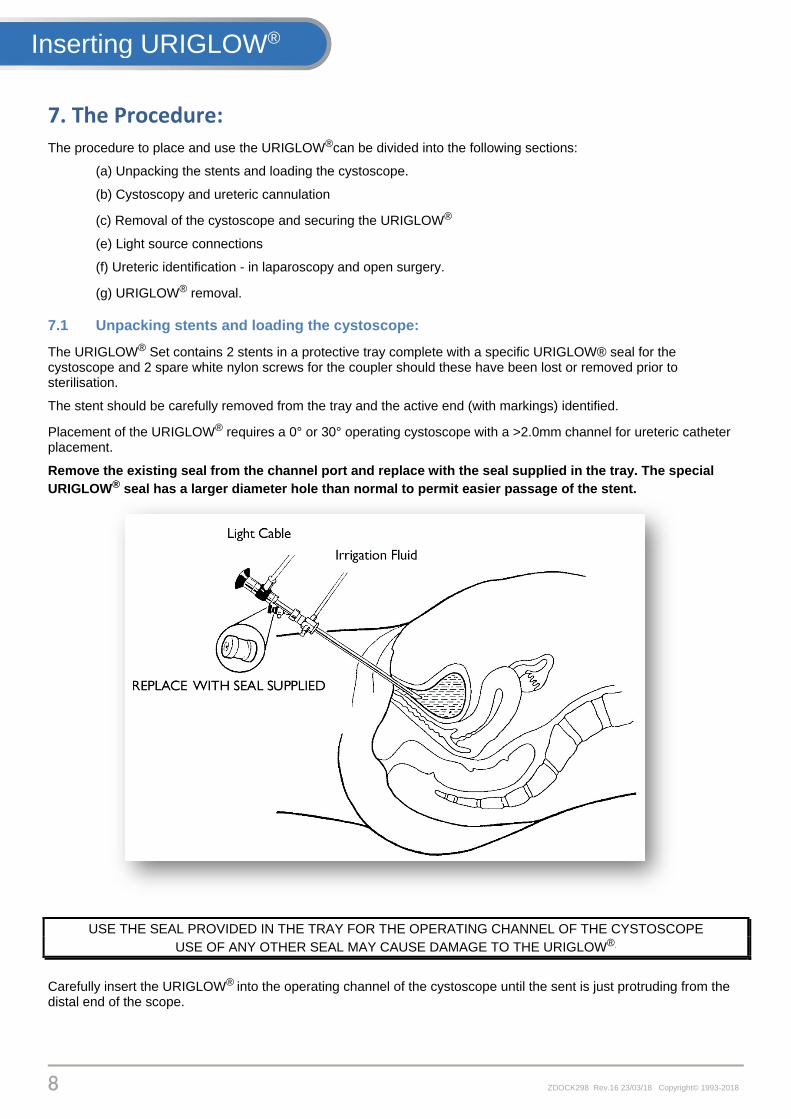
7.1 Unpacking stents and loading the cystoscope:
The URIGLOW® Set contains 2 stents in a protective tray complete with a specific URIGLOW® seal for the cystoscope and 2 spare white nylon screws for the coupler should these have been lost or removed prior to sterilisation.
The stent should be carefully removed from the tray and the active end (with markings) identified.
Placement of the URIGLOW® requires a 0° or 30° operating cystoscope with a >2.0mm channel for ureteric catheter placement.
Remove the existing seal from the channel port and replace with the seal supplied in the tray. The special
URIGLOW® seal has a larger diameter hole than normal to permit easier passage of the stent.
USE THE SEAL PROVIDED IN THE TRAY FOR THE OPERATING CHANNEL OF THE CYSTOSCOPE
USE OF ANY OTHER SEAL MAY CAUSE DAMAGE TO THE URIGLOW®.
Carefully insert the URIGLOW® into the operating channel of the cystoscope until the sent is just protruding from the distal end of the scope.
Inserting URIGLOW®
9 ZDOCK298 Rev.16 23/03/18 Copyright© 1993-2018
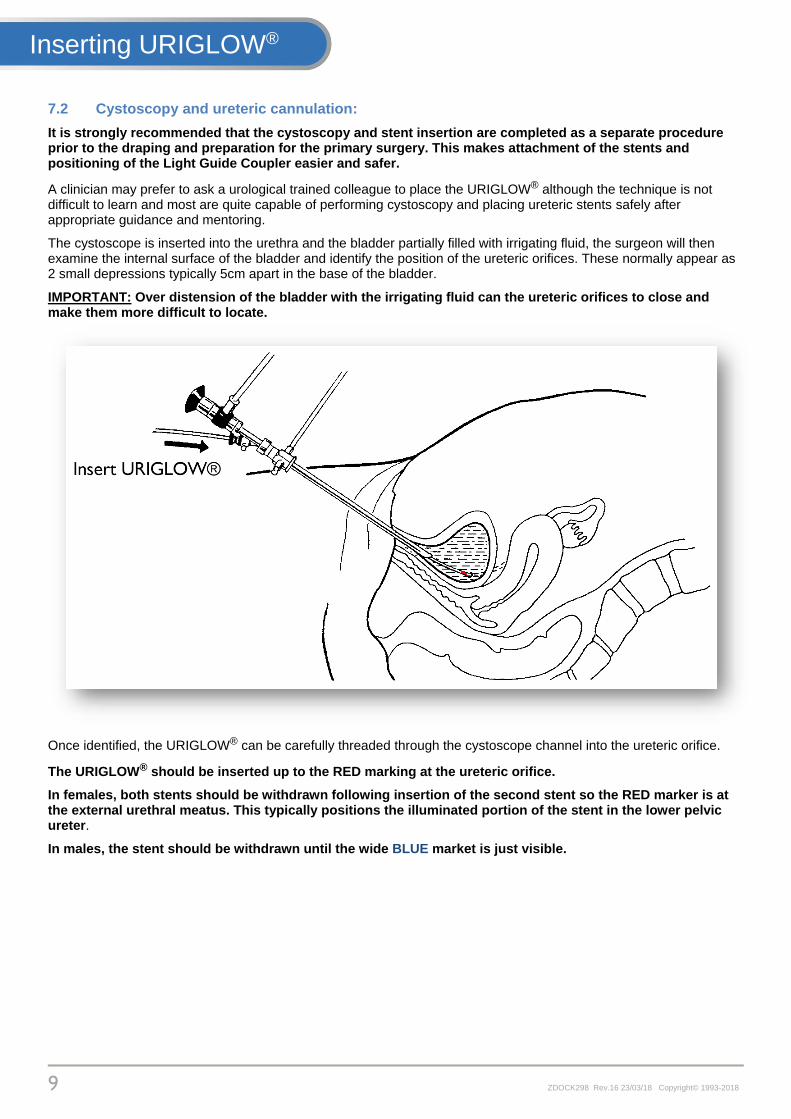
7.2 Cystoscopy and ureteric cannulation:
It is strongly recommended that the cystoscopy and stent insertion are completed as a separate procedure prior to the draping and preparation for the primary surgery. This makes attachment of the stents and positioning of the Light Guide Coupler easier and safer.
A clinician may prefer to ask a urological trained colleague to place the URIGLOW® although the technique is not difficult to learn and most are quite capable of performing cystoscopy and placing ureteric stents safely after appropriate guidance and mentoring.
The cystoscope is inserted into the urethra and the bladder partially filled with irrigating fluid, the surgeon will then examine the internal surface of the bladder and identify the position of the ureteric orifices. These normally appear as 2 small depressions typically 5cm apart in the base of the bladder.
IMPORTANT: Over distension of the bladder with the irrigating fluid can the ureteric orifices to close and make them more difficult to locate.
Once identified, the URIGLOW® can be carefully threaded through the cystoscope channel into the ureteric orifice.
The URIGLOW® should be inserted up to the RED marking at the ureteric orifice.
In females, both stents should be withdrawn following insertion of the second stent so the RED marker is at the external urethral meatus. This typically positions the illuminated portion of the stent in the lower pelvic ureter.
In males, the stent should be withdrawn until the wide BLUE market is just visible.
Inserting URIGLOW®

10 ZDOCK298 Rev.16 23/03/18 Copyright© 1993-2018
7.3 Removal of the cystoscope and securing the URIGLOW®:
After insertion of the first stent, the URIGLOW® is gently threaded through the scope to allow withdrawal.
Avoid 'stripping' the cystoscope along the stent during withdrawal - it may damage the fibre and will reduce light emission.
FEED STENT STEADILY THROUGH OPERATING CHANNEL WHEN WITHDRAWING THE CYSTOSCOPE DO NOT PULL SHARPLY THROUGH CYSTOSCOPE.
The URIGLOW® can be secured to the upper leg with tape, by placing one 10cm piece along the length of the fibre and 2 x 5cm pieces across the line of the stent.
Take care to see that if the legs are to be lowered for surgery, that the URIGLOW® stents are not accidentally pulled out.
The process can then be repeated for the 2nd stent.
ONCE INSERTED, THE STENTS ARE THEN GENTLY WITHDRAWN TO LEAVE THE COLOURED MARKERS LOCATED AT THE EXTERNAL URETHRAL ORIFICE (See above) - TAPE SECURE IN PLACE
Inserting URIGLOW®
11 ZDOCK298 Rev.16 23/03/18 Copyright© 1993-2018
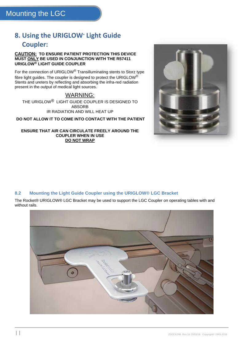
8. Using the URIGLOW® Light Guide Coupler:
CAUTION: TO ENSURE PATIENT PROTECTION THIS DEVICE MUST ONLY BE USED IN CONJUNCTION WITH THE R57411
URIGLOW® LIGHT GUIDE COUPLER
For the connection of URIGLOW® Transilluminating stents to Storz type
fibre light guides. The coupler is designed to protect the URIGLOW® Stents and ureters by reflecting and absorbing the infra-red radiation present in the output of medical light sources.
WARNING: THE URIGLOW® LIGHT GUIDE COUPLER IS DESIGNED TO
ABSORB
IR RADIATION AND WILL HEAT UP
DO NOT ALLOW IT TO COME INTO CONTACT WITH THE PATIENT
ENSURE THAT AIR CAN CIRCULATE FREELY AROUND THE
COUPLER WHEN IN USE DO NOT WRAP
8.2 Mounting the Light Guide Coupler using the URIGLOW® LGC Bracket
The Rocket® URIGLOW® LGC Bracket may be used to support the LGC Coupler on operating tables with and without rails.
Mounting the LGC

12 ZDOCK298 Rev.16 23/03/18 Copyright© 1993-2018
1. The Light Guide coupler should be supported on the uppermost groove
2. Slide the Light Guide Coupler into the opening on the LGC Bracket
3. Slide the Light Guide Coupler down and forward into the slot
Mounting the LGC URIGLOW®

13 ZDOCK298 Rev.16 23/03/18 Copyright© 1993-2018
4. Slide the Light Guide Coupler fully forward until it locks fully into the bracket
Selecting an appropriate side of the operating table, the bracket complete with Light Guide Coupler can be inserted under the table mattress with the wide section innermost.
It is recommended that the coupler and bracket are positioned prior to the placing of the patient onto the operating table, however the positioning of OR equipment may not always permit this.
The Rocket URIGLOW® LGC Bracket is for single use only. It may NOT be autoclaved
ALWAYS EXERCISE CAUTION DURING ANY MOVEMENT OR REPOSITIONING OF THE PATIENT
Mounting the LGC URIGLOW®
14 ZDOCK298 Rev.16 23/03/18 Copyright© 1993-2018
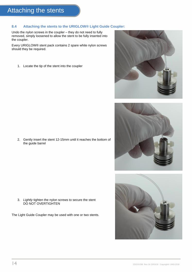
8.4 Attaching the stents to the URIGLOW® Light Guide Coupler:
Undo the nylon screws in the coupler – they do not need to fully removed, simply loosened to allow the stent to be fully inserted into the coupler.
Every URIGLOW® stent pack contains 2 spare white nylon screws should they be required.
1. Locate the tip of the stent into the coupler
2. Gently insert the stent 12-15mm until it reaches the bottom of the guide barrel
3. Lightly tighten the nylon screws to secure the stent DO NOT OVERTIGHTEN
The Light Guide Coupler may be used with one or two stents.
Attaching the stents
15 ZDOCK298 Rev.16 23/03/18 Copyright© 1993-2018
9. Ureteric identification - in laparoscopy and open surgery: Once initial laparoscopy or laparotomy has been performed, it is important to establish the correct position and
function of the URIGLOW® stents.
With the light source activated, the surgeon should examine the lower pelvis for the presence of glowing lines - indicating the track of the ureter.
If the URIGLOW® is not immediately obvious, the surgical assistant should gently withdraw or insert the stent by no more than 20mm - the red marker should normally be at the external urethral orifice to demonstrate the lower pelvic ureter.
The URIGLOW® can be inserted further to demonstrate the mid and upper portions of the ureteric tract.
9.1 Laparoscopic Technique – Use of Shade:
Identification of the URIGLOW® relies on differential illumination. The light emitted by the URIGLOW® Stent must, by definition pass through the ureter and the surrounding tissue.
During the identification process, there is a temptation to approach the surgical area where they are expected to appear, too closely, thus swamping the light output from the URIGLOW® stents with the light from the laparoscope.
There is also a temptation to turn down the laparoscope light source – in modern systems where camera and light source are electronically linked, this may reduce the resolution of the camera and actually reduce visibility.
In both cases the best technique is to withdraw the laparoscope from the field placing the lower or mid pelvis in partial shade. The light from the URIGLOW® then becomes visible – provided the tissue surrounding it are sufficiently thin to permit transmission.
9.2 URIGLOW® Removal:
The URIGLOW® stents are easily removed at the end of the procedure, by gently withdrawing the stent through the urethra. There is normally no reason to re-cystoscope the patient prior to removal of the stents unless there is evidence of active bleeding. Any such evidence must be fully investigated
It is quite normal for the patient to experience a light haematuria for 6-8 hours post insertion as is typical with ureteric stenting. Excessive bleeding should be investigated immediately.
The device is strictly for single use and no attempt should be made to re-sterilise the stent.
Using the URIGLOW®
16 ZDOCK298 Rev.16 23/03/18 Copyright© 1993-2018
10. Light Guide Coupler – Cleaning & Sterilisation The URIGLOW® Light Guide coupler is not sterile in use and in normal usage should only require surface decontamination with 70% Isopropyl Alcohol (IPA) wipes.
If more significant contamination has occurred:
Initial Cleaning: Remove White Securing Screws and discard. Each URIGLOW® Stent set contains replacement securing screws.
Rinse blood and saline solutions from the coupler as soon as possible following use. When cleaning by hand, the coupler should be cleaned with a soft nylon brush under cool or warm running water. Very hot water will cause coagulation of proteinous substances and should not be used.
Mechanical washing machines and ultrasonic cleaners, using instrument detergents of strength recommended by the manufacturer may be used followed by a clean rinse. Neutral (Ph7) detergents should be used during manual, mechanical or ultrasonic cleaning. The use of high pH alkaline detergents may be used but can result in the formation of brown or orange staining on the instrument.
The concentration and volume of detergents used should be in line with the detergent manufacturer's instructions, taking into account regional water quality variations
Sterilisation: The recommended method for sterilisation is steam sterilisation @ 134°C (+3°C – 0°C) for minimum of 3 minutes.
This recommendation should be used in conjunction with the standards and guidelines laid down in ISO 17665-1:2009 (as amended): Sterilization of Health Care Products - Moist heat. Part 1: Requirements for the development, validation and routine control of a sterilization process for medical devices and ISO/TSO 17665-2:2009 Sterilization of health care products: Moist heat - Part 2: Guidance on the application of ISO 17665-1
The URIGLOW® LGC is a precision optical instrument, repeated autoclaving will reduce the overall life of the device
DO NOT IMMERSE IN GLUTERALDEHYDE OR SIMILAR DISINFECTANT SOLUTIONS.
THIS WILL RESULT IN IRREPARABLE DAMAGE TO THE COUPLER
LGC Care
17 ZDOCK298 Rev.16 23/03/18 Copyright© 1993-2018
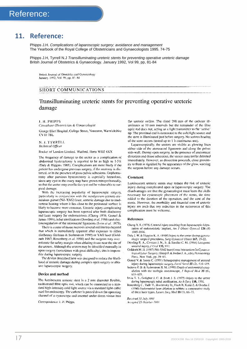
11. Reference: Phipps J.H. Complications of laparoscopic surgery: avoidance and management The Yearbook of the Royal College of Obstetricians and Gynaecologists 1995. 74-75 Phipps J.H, Tyrrell N.J Transilluminating ureteric stents for preventing operative ureteric damage Britsh Journal of Obstetrics & Gynaecology. January 1992, Vol 99, pp, 81-84
Reference:

18 ZDOCK298 Rev.16 23/03/18 Copyright© 1993-2018
12. Rocket Medical Offices: Rocket Medical plc. HQ & Administration Imperial Way. WATFORD Herts. WD24 4XX, England Tel: +44 01923 651400 Rocket Medical plc. Design & Global Production Sedling Road, WASHINGTON, Tyne & Wear. NE38 9BZ, England Tel: +44 0191 419 6988 Global Customer Services: [email protected] Rocket Medical Pty - Australia Suite 209, 1 Katherine Street, Chatswood. NSW 2067, Australia Tel: +61 (0) 431 146448 Customer Services: [email protected] Rocket Medical Canada Inc. 1959 Upper Water Street, Suite 900, Halifax, Nova Scotia, B3J 3N2, Canada Customer Services: [email protected] Rocket Medical - Germany Am Rosengarten 48, 15566 Schöneiche. Germany Tel:+49 30 85994460 Customer Services: [email protected] Rocket Medical Ltd - New Zealand PO Box 07, Albertown, New Zealand Tel:+64 21 945391 Customer Services: [email protected] Rocket Medical - United States 150 Recreation Park Drive. Unit 1. HINGHAM. MA. 02043. USA Tel: +1 781 749 6223 Customer Services: [email protected]
Contacts: