us army armament research and … end of the arm, to apply a moment to ... analysis calculated the...
TRANSCRIPT

CONTRACT REPORT ARBRL-CR-00514
PROJECTILE FOUNDATION MOMENT GENERATION
Prepared by
Battelle, Pacific Northwest LaboratoryP. 0. Box 999
Richland, Washington 99352
June 1983"ATCA
US ARMY ARMAMENT RESEARCH AND DEVELOPMENT COMMANDBALLISTIC RESEARCH LABORATORY
ABERDEEN PROVING GROUND, MARYLAI`D
Approved for public release; distribution unlimited.
C-,
Best Available Copy
C..
83 06 24 048

Destroy this report when it is no longer needed.Do not return it to the originator.
Additional copies of this report may be obtainedfrom the National Technical Information Service,U. S. Department of Commerce, Springfield, Virginia22161.
The findings in this report are not to be construed asan official Department of the Army position, unlessso designated by other authorized documents.
". see us# Q ef :d• i ,a or" H,' ao'u ig ' V?%81 i'e n bhi3 report
""_O 3.tU.itutf 3'l reIwu~t of vy owero-.al produot.

uMLASSIFIEDSECuRITY CLASSIFICATION OF THIS PAGE ("on~t oats Enteted)
REPORT DOCUMENTATION PAGE READ WSTRUCTIONSBEFORE COMPLETING FORM
1. REPORT N .UMBER jZ. GOVT ACCESSION NO. 3. RCIPIENT•' CATALOG NUi.BER
CONTRACT REPORT ARBRL-CR-00514 i_;,,!_ ,__ _/__._- _ _
4. TITLE (and Subtitle) S. TYPE OF REPORT & PERIOD COVERED
YEARLY REPORT FOR FY82PROJECTILE FOUNDATION MOMENT GENERATION S. PERFORMING ORG. REPOPT NUMBER
7. AUTHORf• 8. CONTRACT OR GRANT NUMBER(&)
E.M. PATTONF.A. SIM(INENL.A. STROPE9. PERFORMING ORGANIZATION NAME AND ADDRESS 10. PROGRAM ELEMENT. PROJECT. TA'.K
. BATTELLE, PACIFIC NORTHWEST LABORATORY AREA & WORK UNIT NUMBERS
P. 0. Box 999Richland, Washington 99352 lL162618AH80
11. CONTROLLING OFFICE NAME AND ADDRESS 12. REPORT OATFUS Army Armament Research & Development Command•. June 1983US Army Ballistic Research Laboratory (DRDAR-BLA-S) 13. NUMBER OF PAGESAberdeen Proving Ground, MD 2100514. MONITORING AGENCY NAME & ADDRESS(If dilffrent from Controlling Office) 15. SECURITY CL.ASS. (of thi& report)
• ~ ~UNCLASSIFIED....
IS. DECLASSI FICATION/DOWN GRADI N GSCHEDULE
"16. DISTRIBUTION STATEMENT (of this Report)
Approved for public release; distribution unlimited.
17. DISTRIaUTION STATEMENT (o* the b.t•.rc entered In Block 20, It different from Report)
18. SUPPLEMENTARY NOTES
1S, KEY WORDS (Continue on reverse side It necesaary end Identify by block number)
Projectile Off-Axis Motion Rotating BandBalloting ObturatorYaw-In-Bore In-Bore Dynamics
* Rotating Band Moment Gun Dynamics
20. ABrR ACT (Cauwo so owers* ,k* It nemeat Md ideratif by block number) j mkA project was initiated to develop methods to evaluate the magnitude of
restoring foundation moment generated by cocking of an obturated projectilewhile in bore. An analytical and experimental study was undertaken to assessthe magnitude of this foundation moment for a stationary projectile. Theanalytical portion of the study consisted of a finite element analysis conductedusing the computer code ANSYS. An experimental apparatus was constructed totest the validity of the finite element approach.
DDO 1473 EDITION Ort NOV65 IS OBSOLETE UNCLASSIFIEDSECURITY CLASSIFICATION OF THIS PAGE (When Date Entered)

SCCUITY CLASSIFICATION OF THIS PAQC(ham Data Entem.)
20. (continued)
"The results of this study indicate that the foundation moment is large.A comparison of this foundation-moment to the moment caused by an off-axisrotation of the center of gravity (yaw-in-bore) shows that the foundation momentis equivalent to having the center of gravity at least 2.68 in. (6.8 cm) behindthe axial center of the obturator band of a 120-mm kinetic energy projectile.
-J
S ~UNCLASS IFIED)StCUmiYV CLASIMPICAtION OP ?"IS OA~tMORa 0.'. t"P

TABLE OF CONTENTS
LIST OF ILLUSTRATIONS . .. . .. . . 5LIST OF TABLES . . .. . . . . . . 7INTRODUCTION . . . . . .. .. 9FINITE ELEMENT MODELS . .. . .. . . 12
ELEMENT AND MESH REFINEMENT STUDIES ... .. . 12FURTHER ANALYSIS ..... 16
TEST FIXTURE . • • . . • • • • • 21TEST RESULTS VS.FINITE ELEMENT ANALYSIS . . . . . . 26
BOUNDARY CONDITIONS - FIXED VS. SLIDING . . . . . . 36
MATERIAL PROPERTIES TESTS . . . . . . . . 39IMPLICATIONS OF RESULTS . . . . . . . . . 45
REFERENCES . . . .. . . . . . . 48
APPENDIX A - CLOSED-FORM ESTIMATION OF APPARENT DISCREPANCYIN THE TWO BOUNDARY CONDITION CASES . .. . 49
DISTRIBUTION LIST . . .. . . . .. 57
~i as .5
4'#

LIST OF ILLUSTRATIONS
Figure
1 Cross Section Drawing of M735 - Similar in Design to SeveralLong "Wheel Base" KE Projectiles .. . .. . . 10
2 Cross Section of Analyzer and Tested Geometry . 13
3 3-D Finite Element Model Mesh Showing Restraints, Imposed Dis-placement, and Imposition of the Symmetry Condition . . 15
4 2-D End-On Model of Test Fixture Showing 5 Degree CircumferentialMesh Size, Plastic Band, Restraints, and Imposed Displacement . 17
5 Results of Circumferential Mesh Size Sensitivity Study . , . 19
6 Revised Version of 3-D Model With Slotted Band and 15 DegreeCircumferential Element Size .. . . . .. . 20
7 Photographs of Original Test Fixture .. ... 22
8 Photographs of Test Fixture Installed in its Load Frame. NoteLoad Cell and Clip Gage . .. . . . .. . 23
9 Schematic of Original Test Fixture . .. . .. . 24
10 First Test Results . . . . . . . . . . 27
11 Centerline Deflection for Rigid Fixture and Aluminum Fixture. . 28
12 New Fixture Central Core, Machined From Type 304 Stainless Steel . 30
13 Photographs of New Fixture Central Core . . . . . . 31
14 Finite Element Model of New Fixture Central Core . . . . 32
15 Test Results With New Central Core Portion . . 33
16 Photos of Newly Stiffened Fixture Assembled With Stainless SteelCentral Core . . . .. . . . .. 34
17 Test Results With Newly Stiffened Fixture . . .. . 35
18 Cross Section View of Zytel 101 Tensile Test Specimens . . . 40
"19 Summary of Dynamic and Static Tests Performed on Zytel 101Extruded Bar Specimens . . . . . . . . . 42
A-I4 Idealization of Test Fixture Geometry Showing Both BoundaryCondition Cases: Sliding (Top) and Nonsliding (Bottom) • . 52
SpIIOUs 'AO IU0•t
LAV
4-5

LIST OF TABLES
Table
1 LOAD RATIO FROM ANSYS AND COMPUTATION 37
2 ANALYSIS RESULTS VARYING ENYLON AND BOUNDARY CONDITIONS . 38
3 SUMMARY OF MECHANICAL PROPERTIES TESTS ... . 43
4
7
-7- "~O !A F
p" K
It

INTRODUCTION
This study was conducted by Battelle's Pacific Northwest Laboratory(PNL) for the U.S. Army's Ballistic Research Laboratory (BRL). Thepurpose of this study was to develop methods to evaluate the magnitude ofthe restoring or foundation moment generated by cocking of an obturatedprojectile while it is within the bore of a gun. Saboted projectiles (KE-type) most commonly ride the bore of the gun during launch on what is calledthe obturator or drive band. Stability of the projectile in-bore is most
often provided by two bore contact surfaces located at some distance fromone another (i.e., a long "wheel base"). The rearward surface is provided
by the plastic obturator, and the forward surface is either a plastic bandor steel bourrelet which rides the gun bore. The use of two bore riding
* surfaces results in a greater parasitic weight of the projectile (thesabot) than if there were only one bore riding surface. A cross-sectionview of a typical KE projectile with a long "wheel base" is shown in Figure
The purpose of this project is to develop analysis methods to be
applied in the design of projectiles with one bore-riding surface and withgood in-bore stability. One of the contributing factors to stability isthe righting moment which occurs when the projectile begins to cock inbore. This righting moment will be a function of the stiffness of theplastic obturator or drive band and its resistance to local radialdeformations. The characteristics of this band as well as the stiffness ofthe sabot are therefore very important in determining the resistance of thesingle bore contact projectile to balloting or wobbling in the bore of the
gun.
In the case of the projectile with a long "wheel base," this wobbling
resistance (termed foundation moment) is provided by the separation of two
"-9-

gm
wl
41
int
tA Ln
MCC
Rit
4AL

line contacts with a fairly rigid member between them. In the case of thesingle bore contact projectile, this resistance to wobbling or foundation
moment is provided by the stiffness of the obturator drive band.
This report describes an experimental and analytical study performed
at PNL to estimate the foundation moment. A simplified but characteristic
geometry was chosen which was simple both to model analytically and to
fabricate for experimental studies. Three different finite element models
were constructed for the purpose of evaluating alternate simulation
techniques. An experimental apparatus was also constructed with the same
geometry in order to verify the analytical models. This report documents
the analysis, testing, and conclusions of the project thus far. For the
sake of simplicity, this report looks at the problem in a nondimensionalmanner. The only time that actual dimensions are reported is in the
Implications of Results section in which results of the analysis are scaled
up to what would be seen in an actual gun tube.
-ll

FINITE ELEMENT MODELS
Following a meeting between BRL and PNL personnel in early January
1982, a geometry was chosen for the finite element and testing phase of theprogram. That geometry is shown in cross-section view in Figure 2. Thisfigure shows a plot of a finite element mesh developed for the finite
element code ANSYS.* All finite element stress analyses were performed
with ANSYS. The large diameter portion of the model in Figure 2 is the
"bore-riding" portion of the configuration, and the small diameter
extension serves as the arm by which a moment can be applied to the "bore-riding" portion. The shaded area of the "bore-riding" part models theplastic band or obturator. This plastic band was restrained at its outer
diameter in the radial direction. A transverse deflection was applied atthe end of the arm, to apply a moment to the model. The finite elementanalysis calculated the reaction force at the deflected end of the arm
which in effect gives the moment required to produce the known (prescribed)
angular deflection.
ELEMENT AND MESH REFINEMENT STUDIES
Two- dimensional (2-0) axisyfmetric finite element codes do not
generally allow nonaxs~ymetrtc loading such as that required for thepresent analysis. ANSYS, however, permits the nonaxiisymetric loadirg to
be applied in the form of a sinusoiac variation around the circumferenceof the model. The variation is in the form of A sin Ne, where A is the
amplitude of the loading and N is the number of sine waves applied aroundthe circumference. (One can also specify that the loading is A cos NO.) Byadding up the resu lts of several analyses the solution for a Fourier seriestype of loading can be obtained. Foe this uork, only a single term isrequired To describe the 0. 1-inCh deflection at the end of the model (i.e.,
4 .0.1 cos 4.
*'ANSS 4 d ptOptaty goteliNtg wea1ty~h COMpattt p guit ftd.* V~~mot~t~etd ~m wAmqpte by &Ututwu Awt4si6 SgUten6. tic.

C -
'I I-
a wwU)00.
'a
I- .QJ
z -CI
U I-t wiT NUt r-- -
2 Ut- 3
je-
t-cpa B C
�0S a CN -
.5, 0 -w11111 '.4
i 4'TYVYT a
_ C
*
4
- -- - _________________________________________ Siw a,I 1 0tJ�Jw.a4iS esassni iii. flU Mhill -
S4It'.
4
-1 3�
6

It is possible that the 2-D representation with nonaxisymmetric
loading can give more accurate results than a model using 3-D finite
elements. The 3-D model, for the same cost per computation, must be meshed
coarsely in the circumferential direction, This will cause numerical
•. errors not present in the 2-0 axisymmetric model, which treats circum-
ferential variations in stress in an "exact" analytical manner. The 2-D
element used in ANSYS does not, however, allow material nonlinearities in
* conjunction with nonaxisymmetric loadings. It is expected that the
plastics used for obturator materials will not behave in a linear elastic
tI fashion at the stress levels imposed during launch of a projectile. The
*- ANSYS 3-D element can treat material nonlinearity, and for this reason, a
* 3-Dmodel was also developed as shown in Figure 3. The 2-D model was used
primarily as a guide for evaluating the circumferential mesh refinement
for the 3-D models.
A three-dimensional finite element analysis can involve considerablecomputing costs, since the number of nodes and elements increase rapidly
with the level of refinement of the mesh. In this case, the refinement of
concern is in the circumferential direction. The cost of a finite element
analysis goes up at least in proportion to the increase in number of nodes
and elements, since the number of degrees of freedom directly determines
the size of the system of equations which has to be solved. Nonlinear
materials require iterative solutions, which typically increase cost about
an order of magnitude. For these reasons, it was desirable to determine an
optimum circumferential mesh refinement for the 3-0 analysis.
The 3-D model as shown in Figure 3 has a moment applying arm, a bore-
riding porticn and a plastic band (i.e., shaded region). This model is
meshed into 30 degree segments circumferentially. The element used is the
S .3-D extension of the 2-D isoparametric quadrilateral used in the axi-
symmetric model. It is often describe~d as an 8-node brick element. The
fact that element stresses are computed by ANSYS only at the element
-14-
.S
i•"

I-.7
uoLU 1
0.* A
L4A
0 41
4-)
ow
-44
LL.

centroid gives rise to less detailed stress output than the 2-D models.The 3-0 element does, however, allow material nonlinearities in the form ofinelastic strains which will occur in the obturator material during launch
of a projectile.
Another finite element model was developed as a further check on the2-D axisymmetric model with nonaxisymmetric loading. This model treatsthe large bore-ridina part of the chosen geometry as seen in an end on view.This model, shown in Figure 4, is essertially a flat circular plate of unit(I in.) (2.54 cm) thickness. It is constrained radially (radialdisplacement :0 ) at its outside edge and a small radial displacement (0.01in.) (0.0254 cm) is imposed at its center. The circumferential meshincrement is 5 degrees. The 2-D axisymmetric and 3-D models were alsoconstrained and loaded in this fashion. In addition, the 3-0 model meshwas refined circumferentially from 30 degrees per element to 15 degrees and"10 degrees. In this manner, a sensitivity study was performed to study theeffects of mesh refinement of the 3-0 models. The results are shown inFigure 5. Note that all of the models produced results that differed byless than 10 percent and that even the 3-D model with 30 degree elementsproduced good results. It was thought, however, that a 15 degreecircumferential mesh refinement, although not required in the linearelastic analyses, would be desirable when material nonlinearities wereadded to the model. The 15 degree circumferential mesh refinement wastherefore chosen for the remainder of the 3-D modelling.
FURTHER ANALYSIS
The material properties used initially for the plastic band weretaken from handbook values. It was also originally thought that a rigidrepresentation of the metal parts would be adequate. For the plastic band
"A material values of 175,000 psi (1207 MPa) for Young's modulus and 0.4 for
-16-
• 4

I--<I-Ij
zn'.4 a)0EQ
V)~ (A
co
CL
V-)
Ci
L a)
LL.

Poisson's Ratio were chosen on the basis of manufacturers' data and
discussions with staff in PNL's Materials Department. These values and a
Young's modulus of 30 X 108 psi (20.7 x 10⁶ MPa) (2 orders of magnitude morestiff than steel) for the metal core of the model produced the results
shown in Figure 5.
During the course of this project several aspects of the models usedin the above described element selection and mesh refinement study were
changed. The most notable changes were the properties of the plastic usedfor obturator band material, and the geometry of the metal portion of themodel. A small variation in the banded (bore-riding) part of the model was
required to produce a band that would not slip during testing. Thatgeometry is shown in Figure 6. It is essentially identical to that shownin Figure 3 except that the plastic band has a thicker portion which fitsinto a central depression in the metal core. This eliminated any
possibility of slip in the axial direction at the core-plastic interface.
A second, much more significant change had to be made in the geometry
of the moment-applying bar portion of the model. Initial testing and
analysis showed an unexpectedly high moment generated by the plastic bandand associated bending of the bar. Therefore,it was decided to stiffen the
bar considerably.
The elastic properties of the plastic obturator material were alsochanged during the course of this project. Initial handbook values for
- Young's modulus proved to be much lower than the actual material used inthe testing phase of this work. Material tests performed as part of this
-project are described in another section of this report.
Du PuPont Pla.ttu Ve6ign Handbook, page 15, Tr.bte S.
*", -18-
0]•

LM
LUw
w
w
r4 w ewe -
(5)0~

U. C
UwU
4-j
x toIJ.s 0 4-
W a)cu
t.0
200

TEST FIXTURE
The original test fixture built to measure the foundation moment is
shown in Figure 7. Figure 8 shows a series of photographs of the fixture
in the load frame used for the tests. Figure 9 is a schematic of the
original test fixture. The central portion of the assembly is made of
aluminum bar stock. The aluminum portion comes apart in the middle toallow installation of the plastic band. Four hardened cap screws were used
to fasten the aluminum end cap which holds the plastic band in place. Once
this aluminum and plastic assembly is put together, it is bolted into the
steel frame shown schematically in Figure 9 and pictorially in Figures 7
and 8. This steel frame consists of a bottom plate and an upright member
which is split horizontally to allow installation of the aluminum and
plastic assembly. In this fashion, a simulated projectile (aluminum and
plastic assembly) is assembled into a short section of a simulated gun tube
(steel clamping device). The inside of the steel clamping fixture and the
outer surface of the plastic band had machined grooves to prevent slippage
along the plastic-steel interface. To ensure proper clamping of the
aluminum and plastic assembly, an interference of approximately 0.005 in.
(0.013 cm) was provided in the steel clamping device. The bottom of the
upper semicircular clamp was machined off to provide this interference.
The plastic band in the test fixture was machined from a tube of nylon
ordered from DuPont. The tube is centrifugally cast ZYTEL 101 with an
outside diameter of 3-1/8 in. (7.9 cm) and an inside diameter of 1-1/4 in.o• (3.2 cm). The material was specified with a military specification common
to most of the KE obturators. This specification is: nylon tube,
centrifugally cast, ZYTEL 101, composition "A," Type I, MIL-M-20693.
This entire assembly was placed in a load frame. This frame consisted
of a handcranked bottom platen which moves the specimen up to contact a
-21-
S , • . , , . . •

FIGURE 7. Photographs of Original Test Fixture
-22-

FIUR 8. Phoogrph of Tes Fixur Intale in it Loa Frame. - -- *
Not Load. CeladClpGg
-23

-No.
yNYJ
- S.0NNN %:%U
.0 .a'
~1* -24-

mandrel which is bolted to a BLH Electronics Type UG32 load cell. The loadcell signal was conditioned with a Doric Digital Transducer IndicatorModel 420 with analog output. The capacity of this load frame was 10,000lbf (5450 kg). A clip gauge was placed between the bottom plate of thefixture and the end of the moment applying arm (aluminum arm). This clipgauge is a doubly cantilevered gauge with four micromeasurement straingauges connected in a wheatstone bridge. The output signal from the gaugewas conditioned with an Endevco Model 4470 voltage regulator bridgeconditioner. This signal, combined with the output from the BLHelectronics load cell, was fed to a Honeywell Model 1540 X-Y chartrecorder. The entire system was calibrated and used to obtain a plot of
force versus deflection at the end of the aluminum bar.
-25
I2.

TEST RESULTS VS.FINITE ELEMENT ANALYSIS
The results of the first test are shown in Figure 10. Note that the
force required to deflect the end of the aluminum bar by 0.1 in. (0.25 cm)
was about 180-190 lbf (82-86 kg). The initial finite element analyses
treated the metallic parts as essentially rigid because it was thought that
the resisting moment (foundation moment) would be fairly small. It is most
commonly treated as a higher order effect in ballistic analyses of
*. projectiles.
-. The initial analyses predicted forces much greater than the 190 lbf
(86 kg) output from the test. The forces calculated by ANSYS were in excess
of 1300 lbf (590 kg) and in one case as high as 8200 lbf (3720 kg), computed
'9. by using different restraint conditions. Explanations were sought for the
obvious difference between the analysis and the test. A possible source of
the discrepancy was the compliance of the test fixture. To check for
compliance the actual modulus of elasticity (10 X 106 psi) (69 x 103 MPa)
was used for the aluminum central portion in the ANSYS model. The
calculated reaction force at the end of the aluminum bar dropped from 1390
. lbf (630 kg) to 325 lbf (147 kg). The fixture was obviously much too
"compliant to be modeled as a rigid member in the finite element simulation.
Figure 11 portrays graphically the difference betwen a rigid center and an
alwninum center. It is a plot of the cenuerline deflection (as calculated
by ANSYS) of the fixture for two cases; one with the center portion
modelled as rigid (E a 30 X 108psi) (20.7 x 10⁶ MPa), and one for an
alhtinum centee (E - 10 X 106 psi) (69 x 103 tPa). Note that almost all of
the deflection in the case of the aluminum center consists of bending in
the bat.
* To .minimize undesired bending of the bar, a new central core was
designed and manufactured from a single bar of 304 stainless steel. A
•46

- cw�'�' -.- � - � -- - �
.1I II **1
Ku I
I &I I.
I I IU
w*1' F-
0
wa.-II I a
I - La..0
I 0 0
I I --I* La.
Ii U--a
- - m -
(t*ISIAIP 8*U (kg ss*)'�u oI) avoi
-2?'.
0

#A
LM
(ALA
In r4
V
D 4-.
x 0
wL 04.)
:2Q
'cu
xL
LAU
o *1**

Ia
schematic of this central piece is shown in Figure 12, and photographs of
it are shown in Figure 13. A slot was added to thp rear portion of the arm
to get clearance for the clip gauge in the test setup. The ANSYS model for
this new central portion is shown in Figure 14. Because the interest was
in the behavior at the plastic-to-bore interface, it was unnecessary to add
the notch geometry to the ANSYS model. The results for this ANSYS model
which treated the compliance of the stainless steel rod (1314 lbf) (597 kg)
were reasonably close to the results of the rigid center case (1375 lbf)
(624 kg).
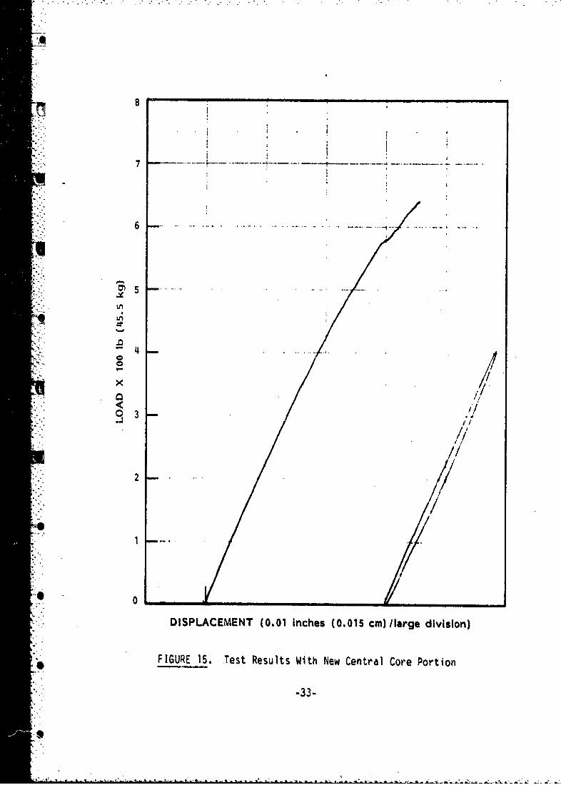
The tested results for this new central core clamped in tne origihal
fixture are shown in Figure 15. The clamping fixture was then also
"stiffened as shown in the photographs of Figure 16. The results of tests
with the newly revised fixture are shown in Figure 17. If the measurementsfrom the last test are corrected for bolt stretch in the clamping device
and for bending of the bottom plate of the clamping device, the test data
indicate that it will require approximately 1800 lbf (810 kg) to deflect
the end of the fixture 0.02 in. (.05 cm). Further predictions were made
using ANSYS. These predictions use a 0.02 in. (0.05 cm) fixture end
deflection, the stainless steel core, and a nylon elastic modulus of
600,000 psi (4140 MPa). The measured result of 1800 lbf (810 kg) is bounded
by two predictions varying boundary conditions: fixed axially and radially
at the plastic gun bore interface, and fixed radially only at this
interface.
/I
-29-
t-' -l _ 4 - 1
,,

0. 33" 0. 17"(8.4mm) (9.3mm)I _Si 0. 1 _ ! .33"
• 2.- " ' -8. 4mm )(12.7cm)
ii 2.4"
"1. 1"2.)
-A
_ FIGURE 12. New Fixture Central Core, Machined FromType 304 Stainless Steel
-
:12, -3C-
4i
1. .

Y 1
wl4'
4". ý
'4M
FIGURE 13. Photos of New Fixture Central Core
-31-

u a
ww
CL 0
CLU
UC
UUCl
UU
ax
0
-- 33
i*1
I I
=,,
0•J 0
DIPAEMN 0.1Ichs(.15c)/,rediiin
FIUE15 et eutsWt ewCnra oeXoto
.33;
0e

IT
la%
-34-
Ip

LA
.4)
-- 35
11
- ".,
' D SPL CEM NT 0.0 in he 10 025 cm) lar e d vis on
FI U E 1 . T s es l s W t nly t f e e i t r
S..... 35
iC

."
BOUNDARY CONDITIONS - FIXED VERSUS SLIDING
The boundary conditions at the plastic-to-gun-bore interface are acritical aspect of the analysis. In order to model this interface usingANSYS, the outer nodes of the plastic band were assigned zero displacementvalues in specified directions. This essentially models the gun bore as arigid boundary. These nodes could be fixed in the radial, axial or
circumferential directions. The method used to generate the nodal pointsused a cylindrical coordinate system. In the convention of the ANSYS codethis means that fixing a node in the X-direction was the same as fixing itin the radial direction. The Y-coordinate coresponded to the tangential(or e) directicn, and the Z-coordinate corresponded to the axial direction.Since the simulation did not include twisting of the projectile in-bore(i.e., a smooth bore bullet), the displacement in the e-direction was not
constrained. This leaves two options, nodes fixed only in the R-direction(radially), or in both the r and Zdirections (radial and axial). The test
fixture had circumferential grooves machined into it as mentioned before,so it would seem reasonable to expect that the plastic would not slipaxially in the test. In a gun tube, however, the plastic is always slidingaxially along the bore surface. In this light, it is more reasonable to fixthese points in the radial direction only when modeling actual projectile
behavior. In order to both model the condition of the test fixture, and• .shed some light upon the actual foundation moment under launch conditions,
both of these cases were analyzed. The analyses of these two cases* produced some surprising results. If we assume that the end deflection of
the bar is 0.1 in. (0.25 cm) as before, ANSYS predicted reaction forces of
1314 lbf (597 kg) when only radial displacements were fixed and 7280 lbf
(3305 kg) for the case where the outer plastic nodes were fixed in both theradial and axial directions. This is a factor of over 5.5 differencebetween the two cases.
-36-
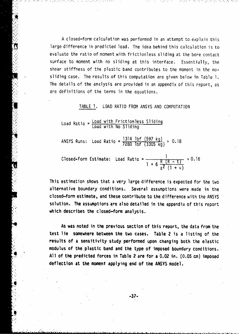
A closed-form calculation was performed in an attempt to explain thislarge difference in predicted load. The idea behind this calculation is to
evaluate the ratio of moment with frictionless sliding at the bore contactsurface to moment with no sliding at this interface. Essentially, the
shear stiffness of the plastic band contributes to the moment in the no-sliding case. The results of this computation are given below in Table I.The details of the analysis are provided in an appendix of this report, as
are definitions of the terms in the equations.
TABLE 1. LOAD RATIO FROM ANSYS AND COMPUTATION
LaRt Load with Frictionless Sliding- .'. L o a d R a t i o =Load with No Sliding
• 1314 Ibf (597 kg)ANSYS Runs: Load Ratio = = 0.187280 lbf (3305 kg)
Closed-Form Estimate: Load Ratio 1 0.16S~I + 6 I
This estimation shows that a very large difference is expected for the twoalternative boundary conditions. Several assumptions were made in the
closed-form estimate, and these contribute to the difference with the ANSYS
solution. The assumptions are also detailed in the appendix of this report
which describes the closed-form analysis.
:4 As was noted in the previous section of this report, the data from the
test lie somewhere between the two cases. Table 2 is a listing of the
results of a sensitivity study performed upon changing both the elasticmodulus of the plastic band and the type of imposed boundary conditions.
0 All of the predicted forces in Table 2 are for a 0.02 in. (0.05 cm) imposed
deflection at the moment applying end of the ANSYS model.
"-37-
S,

TABLE 2. ANALYSIS RESULTS VARYING ENYLON ANDBOUNDARY CONDITIONS
Force PredictedENylon by ANSYS
(psi) (MPa) Fixity (lbfJ (kg)
175,000 (1207) Radial 268 (122)175,000 (1207) Radial + Axial 1,456 (661)
370,000 (2550) Radial 540 (245)
370,000 (2550) Radial + Axial 2,683 (1218)
600,000 (4130) Radial 829 (376)
600,000 (4130) Radial + Axial 3,780 (1716)
Two trends are immediately apparent upon examining this table. First, the
boundary conditions imposed upon the model are very important in deter-mining the predicted system stiffness. In all cases there is at least a
factor of 4.5 difference in predicted force between the two alternate
"boundary conditions. Second, the relationship between the elastic modulus
of the band and foundation moment is not linear. An increase in elasticmodulus by a factor of two does not increase the stiffness of the system bya factor of two. This is at least partly because deformation of the steelcore pleys an increasing role in tVe flexing of the fixture with increasing
band stiffness. This result shows that modelling the metallic parts asrigid is not a valid assumption. It also shows that the interaction
between obturator and sabot, and the deformations of the metallic parts of
any projectile play a significant role in determining the magnitude of thesystem stiffness and contribute to the balloting response of the pro-
jectile. Any design strategy which deals with foundation moment musttherefore include the compliance of the metallic parts of the projectile.
3
.•. -38-
"i

MATERIAL PROPERTIES TESTS
The only mechanical properties available for the specific plastic
used to fabricate the band were minimum manufacturer's specifications. As
such, it was decided that material characterization tests for the plastic
were necessary to permit detailed comparisons of finite element pre-
dictions with test results. Both the low strain rate and moderately high
strain rate regions were of interest since the elastic modulus and yield
"strength of the plastic were believed to change with changing strain rate.
Both properties were expected to increase with strain rate.
"Initial mechanical properties tests were performed using some ex-
"truded ZYTEL 101 bar stock that was available in PNL's Materials Department
from another project. Figure 18 shows the tensile specimens machined from
this material. Initially, those specimens were machined from this bar
stock. All three were machined from longitudinal sections of the bar;
i.e., the long axis of the specimens was in the extrusion direction of the
bar. The first specimen was pulled in tension to failure in an Instron
tensile test machine. This was the "low strain rate" test. The head speed
S"(rate of elongation of the specimen) was .02 in./min (0.051 cm/min).
Another low strain rate test was performed in a similar manner except that
the material was stressed above yield, then unloaded, and then cycled up to
a stress above yield again. This cycling was repeated four times, and then
the specimen was pulled in tension to failure. This cyclic testing was
performed to study the anelastic or hysteresis behavior of the nylon
material. 'he test results do show a significant amount of this type of
behavior. This behavior was studied in this fashion because of the
hysteresis seen in the .bench tests (Figures 15 and 17). The shape of the
Instron test curve is in fact very similar to that seen in the bench tests.
The third specimen was pulled to failure in tension at a high rate of
strain. The specimen was loaded into a drop tower and impacted by a fal I ing
S_30

"9/16" THREAD
(51c)
0,.25" 2"1
a'. .
FIGURE 18, Cross Section View of Zytel 101 TensileTest Specimens
.40-

weight. The velocity of the falling weight was 3180 in./min (8077 cm/min).This yields strain rates 160,000 t.es higher than those used in the slowrate tests. The entire high strain rate testing event took place in 3.12msec from the initial impact. Results from the high strain rate (dynamic)"and low strain rate (static) tests are summarized in Figure 19. The elasticmodulus for the low rate of strain tests is 370,000 psi (2250 MPa) and forthe high rate of strain tests it is 520,000 psi (3590 MPa) for thisparticular nylon. The third sample, before impact testing, was also testedultrasonically to determine the dynamic modulus of elasticity. This testproduced a modulus of 520,000 psi (3590 MPa), as in the impact test.
Test specimens were also cut from the centrifugally cast tube boughtfor this project. These specimens were cut from the same material as thenylon bands used in the bench test fixture. Three tensile specimens,
identical to those used previously, and one compression specimen (acylinder 2-1/2 in. (6,4 cm) long and 3/4 in. (1.9 cm) in diameter) were cutfrom this material. One of the tensile specimens was placed in a bucket ofwater overnight before testing to determine the effect of water absorptionon the mechanical properties of the nylon material. Two of the tensilespecimens were tested statically (low strain rate): one dry (65% relativehumidity in the lab at the time) and one wet (out of the bucket of water).These two were tested ultrasonically before being pulled to failure on theInstron. The third tensile specimen cut from the tube was loaded into the
Sdrop tower and tested dynamically (high strain rate). The compressionspecimen was tested in the Instron at.the low strain rate..4
A summary of the results of all of the nylon mechanical propertiestests performed for this project is provided in Table 3. There are a fewimportant things to note in this table. First, the elastic modulus of thedelivered nylon product is considerably above minimium manufacturers'specifications. These specifications. were taken directly from the
-41-
Il

ZYTEL, 101 TENSILE STRESS-STRAIN DATA
1.?o
DYNAMIC.. v - ; : v " . " ". " .* . . .
I.') :,,%
LO 0.8 E=520,000 PSI (3590 MPA) ...
Ntoo
.-. ., E 370,000 PSI (2550 MPA)'0.4
.a ,*STATIC0.00.0.6.
0.2. -0
1.S
L0
"E 0..0h0 P.2I .50 (.25 2.00
DEFLECTION, X .1 iN. (.25 CM.)
FIGURE 19. Summary of Dynamic and Static Tests Performed onZytel 101 Extruded Bar Specimens
.42-S,

CL. )r-. r-- CJ-
4-) 4-J
LA)
- - -M
LfI. :) Lo I I
-c
a)
-0
LU.
ton0j
x f'CJ 'O
0j
CL LLr Ic C4 %Q Ln. N..N
U 10
CLL
4.4
6~.t V~
L L)U L'..f) u o
444
* C
0 I
S -43-

manufacturers' specifications. Another handbook of material properties of
plastics 2 quotes a somewhat higher modulus for the product. This
reference quotes 350,000 psi (2410 MPa) for cast nylon type 6 and 200,000
psi (1380 MPa) for nucleated nylon type 66. The variability in quoted
mechanical properties points to a second important conclusion to be drawn
"from the mechanical properties tests. That is that even Young's modulus is
different for different product forms and possibly even for different lots
of the same material. This is not the case in metals. Thus, it is not
reasonable to treat these plastics in our simulation as we would metals.
Another rather important note to be made relates to the effects of
rate of strain upon the mechanical properties of nylon. Within the same
lot of material, the rate at which the material is strained determines in
part the elastic response of the material. Both of the materials tested
(extruded bar and spin-cast tube) exhibit this behavior. The rate of
strain imposed upon the impact test specimens was similar to what could be
expected to occur during launch of a projectile.
I
SModem Plahtic6 EmtcydopediA, Octobet 1915s Vo&&rne S2, Ntumbet IOA,Me.Gtw-HIU PubLicationi Comp'uJg, New Vo,,a, NV.
-44-
I' r- •

IMPLICATIONS OF RESULTS
Historically, it has been assumed that the foundation moment for asingle bore contact projectile is rather small and would have a second
order effect on projectile motion. The results of this project indicatethat the foundation moment in a short wheel base round is not a neglectable
effect. This will be shown with a relatively simple calculation.
If we presume
* qthat the modulus is more likely to be near 600,000 psi (431 MPa) as a
consequence of the materials test,
*..that the lower values for the moment are more nearly correct (the
sliding case), and
- that the results are amenable to linear scaling,
then the calculations can be made to evaluate the effective magnitude of
the restoring moment for a 120-mm projectile (KE). For a deflection of0.02 in. (0.051 cm) related to the test apparatus, the net foundationmoment generated for the 2.8 in. (70 mm) diameter band can be computed from
M70 = F d
= (829 lbf)* (5.5 in.)
- 4565 in,-Ibf (5264 cm-Kg)
. Now estimating the moment for a 120-mm diameter projectile, presuming that
"the length and thickness of the band are unchanged, gives
'.': t12oM12 M710
4 (4565 in.-lbf) (\--)
= 7825 in.-lbf
"M120 7800 in.-lbf (8995 cm-Kg)
4 *This value is taken directly from Table 2 for a nylon Young's modulus
of 600,000 psi (4137 MPa) and fixed R-direction only.
-45-
S. . " -

The 0.02 in. (0.051 cm) deflection at the moment applying end is
equivalent to about 0.21 degrees of angular deflection. To calculate the
value of the peak moment generated by having the center of mass of the
projectile at some axial distance from the position of the obturator band
"(the hinge) and at the same angle, we will assume a peak axial acceleration
of 50,000 g's and a projectile weight of 16 lbm (7.26 Kg).* The resulting
moment is given by
Macc (Facc) (tan a) (g)
where
Macc = peak moment due to acceleration.
Facc body force due to acceleration mass of round x axial
acceleration (16 lbm) x (50,000 g's) 800,000 lbf (363,200 Kg)a angular displacement, and
2 = axial distance between center of gravity and center of
obturator band.
We can now solve for Lmin by equating the two moments, or
Macc.- +.• min =2.min Facc tan
7800 in.-lbf(800,000 lbf) (tan .210)
= 2.68 in. (6.81 cm)
. In other words, the foundation moment in this case will equal the peak. torque produced by the center of gravity being about 0.6 caliber ahead of
the axial center of the obturator band. If the band restoring moment turns
out to be greater, or if times other than peak propelling gas pressure are
.. considered, the foundation moment is even more important.
These figures are representative of a 120-mm KE bullet.
"-46-
Uo

It should be recalled that several assumptions were made in the above
calculation. For example, instead of using the results of the bench tests
in which sliding was restrained, we used the results of the analysis of the
same geometry in which sliding was permitted. The properties of the
plastic were taken from results of mechanical properties tests. Linearly
* elastic behavior with no yielding was assumed. The measured yield strength
of the plastic is about 12 kpsi (82.7 MPa), and the outer portion of the
plastic in the analysis showed a stress of approximately that magnitude.
Also, the analysis results were scaled from a 2.8 in. (70 mm) assembly to
a 4.7 in. (120 mm) assembly.
If any one of the above assumptions is invalid, the comparison
calculation could be inaccurate, We believe, however, that the assump-
tions made yield results that are conservative in the event that they are
inaccurate. It, therefore, seems reasonable to expect that the foundation
moment is a large effect and must be included in any calculation involving
the dynamics of an in-bore projectile. There are several parameters to the
problem which, however, warrant further investigation. Bench tests should
be performed with a model projectile sliding within a model gun tube.
Different grades of plastics should be used: for example, centrifugally
cast versus extruded material. This will show the effect of typical
variations in the mechanical properties of the plastic band material. The
geometry of the band should also be changed to assess the effects of
changing the thickness of the band and the length of the bore contact
surface. Finally, the importance of the hysteresis must be explored as a
damping mechanism for balloting motion.
-47-

REFERENCES
1. DuPont Plastics Design Handbook, page 15, Table 5.
2. Modern Plastics Encyclopedia, October 1975, Volume 52, Number IOA,- McGraw-Hill Publications Company, New York, NY.
A_.48
I.I
R'4
li" -48-

APPENDIX A
CLOSED-FORM ESTIMATION OF APPARENT DISCREPANCY INTHE TWO BOUNDARY CONDITION CASES
-49-
0,

APPENDIX A
This appendix contains a calculation to resolve the apparent dis-
crepancy in analysis results for the two different boundary condition
cases: sliding or no sliding. In the sliding case, the gun bore-nylon
interface is modeled as friction free and only the radial compliance of the
nylon withstands the applied moment. In the no-sliding case, both the
radial compliance and the shear stress at the gun bore-nylon interface will
withstand the moment.
Figure A-1 portrays symbolically the two different boundary condition
cases. The upper portion shows the sliding friction free case, and the
lower portion shows the no-sliding case. Let us define terms as follows:
I, = length of gun bore to nylon interface (width of obturator)
t = thickness of nylon
U R = radius of center of projectile
r radial position or direction
"z longitudinal or down-bore direction
E = nylon Young's modulus
EG = nylon shear modulus 2(0 + V)
v nylon Poisson's Ratio
e rotation of projectile about the center - this rotation causes*e the moment
u = displacement in the radial direction (r direction)
v a displacement in the longitudinal direction (z direction).
*,e First, we will look at the no-sliding case. The relationship between
shear stress and shear strain can be given by Hooke's Law as follows:
G,,T =G Vduz dv
I ... 51-
A U •-f "lBs.X,. •->-_-

ut r Sliding
- -R
wv R
:7 7 7 77 7 )Non-sliding
"FIGURE A-I. Idealization of Test Fixture Geometry Showing BothBoundary Condition Cases: Sliding (Top) andNonsliding (Bottom)
"-52-
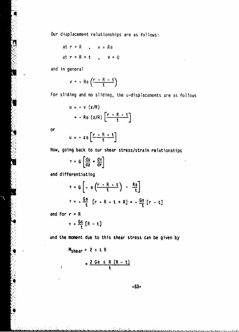
Our displacement relationships are as follows:
at r = R , v Re• ,4
at r=R+t 0 v
and in general
v = -Re r - R -t-" t
For sliding and no sliding, the u-displacements are as follows
"* u - v (z/R)
::iZ - -Re (z/R) t
or
U u .ze [r- R-t]
"Now, going back to our shear stress/strain relationships
TG u dvLdz dr]
and differentiating
-[ (r R -t) Re• :, T G "t " -
Go - R - t + RR] Ge tr Qt
and for r * R,-.-T ( R -qt
t
"and the moment due to this shear stress can be given by
"" Msheara 2 T t R
2Ge G t R (R - t)I 2t
"-53-
S

and from our shear modulus/Young's modulus relationshipsSE ezR(R - ,l
Mshear tt (1 + IV)
The radial stress at any point, Or, can be given by
E d E [Oz (l/t)]
.L".-/E e z
and the moment due to this radial stress can be given by
Mradial 2 Z Or dz
12Ee z2 dz
.2/f2 -2 1
-Ee 3
Eq3--- 6t
Now, what we want is a measure of the difference between the two boundary
condition cases, or a ratio as follows
Moment due to orRatio Moment due both to Or and T
or
* Ratio Eet 3/6t
Eet 3/6t + EW JR -t (I + •
W54-
4... . -- 4

or, after some algebraic manipulation
"" • 1Ratio =
- + 6 12 (1 + v)
Taking values of the dimensions from our test fixture, as follows:
t = 0.2 in. (0.51 cm)
R = 1.2 in. (3.05 cm)I = 1.0 in. (2.54 cm)
V 0.386 (from material test data)
. Then the ratio can be evaluated as follows
Ratio•::: ~ ~~~I + 6 •,'Z( .36
Ratio 0.16
From our finite element results, the ratio of results can be evaluated as
follows and ,compared to the. closed-form solution:
- 1314Ratio From Finite Element Results 1
"Ratio Calculated 0.18
The closed-form estimate is based upon many assumptions, such as a
rigid representation of the metal parts. The difference between the 0.16
calculated closed form and the 0. IS calculated using ANSYS is therefore not
considered significant. The fact thot the ratio is so small, or that the
shear stress plays such a major role in determining the moment is, however,
a significant finding.
S
45.
SO
-: -A- .5--

DISTRIBUTION LIST
No. of No. ofCopies Organization Copis Organization
12 Administrator 1 CommanderDefense Technical Info Center US Army Materiel Development
SATTN: DTIC-DDA and Readiness CommandCameron StationAlexandria, VA 22314 ATTN: DRCDMD-ST
5001 Eisenhower AvenueI Director of Defense Alexandria, VA 22333
Research & Engineering (OSD)ATTN: Mr. R. Thorkildsen I CommanderWashington, DC 20301 US Army Materiel Development
and Readiness Command1 "..Director of Defense ATTN: DRCLDC, fir. T. Shirata
"Research & Engineering (OSD) 5001 Eisenhower Avenue* ATTN: Mr. 3. Persh Alexandria, VA 22333
Washington, DC 20301 Commander
US Army Materiel Development1 Director and Readiness Command
Defense Advanced Research ATTN: DRCDE, Dr. R.H. HaleyProjects Agency Deputy Director
1400 Wilson Boulevard 5001 Eisenhower AvenueArlington, VA 22209 Alexandria, VA 22333
1 Director CommanderInstitute of Defense Analysis US Army Materiel DevelopmentATTN: Documents Acquisition and Readiness Command1801 Beauregard StASAlexandria, VA 22311 ATTh: DRCDE-R
5001 Eisenhower AvenueI HQDA (DANA-MS) Alexandria, VA 22333
Washington, DC 20310ICommander
I HQDA (DA4A-ZA) US Army Materiel DevelopmentWashington, DC 20310 and Readiness Command
ATTN: Mr. LindwarmI HQDA (DAPA-ZD, H. Woodall) 5001 Etsenhoeer Avenue
Washington, DC 20310 Alexandria, VA 22333
1 HQDA (DA14A-ARZ-A, Dr. M.E. Lasser) 8 CommanderWashington, OC 20310 USA ARRADCO4
SATTN: DRDAR-LCA, Mr.. A. Hoss2 HQDP (OAHA-CSN-VA) DRDAR-LC, J.T. Frasier
(DAMA-CSH-CA) DROR-SEWashington, DC 20310 DRDAR-SA
DRDAR-AC1 HQDA (DI4A-CSS-T, Dr. J. Bryant) IRCMR-LCU-SE, O. Pearson
* Washington, DC. 20310 ORDAR-LCA-Ml, F. SaxeDRDAR-LCU-SS, R. Botticel I.
Dover, NJ 07801
.-57.- *Act*. -t|aaIVwu.lPAca .i-n

DISTRIBUTION LIST
No. of No. ofCopies Organization Copies Organization
5 Commander 7 CommanderUSA ARRADCOM USA ARRADCOMUSA AT RDC S, ATTN: DRDAR-SCA, C.J. McGeeATTN: DRDAR-SCS, Mr. D. Brandt DVDAR-SCA, S. GoldsteinDRDAR-SCS-E, Mr. J. Blumer CRDAR-SCA, F.P. Puzychki•.. ~~~~DRDAR-SCF, Mr. G. Del Coco DDRSA .. Pzck
D RDAR-SCA, E. JeeterDRDAR-SCS, Mr. S. Jacobson DRDAR-SCA, M. JeeteDRDAR-SCF, Mr. K. Pfleger DRDAR-SCF, M.j, Schmitz
..Dover, , 97801 DRDAR-SCF, L. Berman,-DRDAR-SCZ, P. Petrella
Dover, NJ 07801
_-.2 CommanderUSA ARRADCOM 9 CommanderATTN: DRDAR-TSS USA ARRADCOMDover, NJ 0780" ATTN: DRDAR-SCMDRDAR-SCM, Dr. E. Bloore
4 Commander DRDAR-SCM, Mr. J, Mulherin"USA ARRADCOM DRDAR-SCS, Mr. B. Brodman
DRDAR-SCS, Dr. T. HungAT. DRuDAR-TD DRDAR-SCA, Mr. W. Gadomski
DROAR-TDS DRDAR-SCA, Mr. E. MalatestaDRDAR-TDC, Dr. D. Gyorog DRDAR-SCA-T, P. BenzkoferDr A Dr D8 DRDAR-SCA-T, F. Dahdouh
Dover, NJ 07801 Dover, NJ 07801
5 CommanderUSA ARRADCOM 3 Commander
ATTN: DRDAR-LCU, Mr. E. Barrieres USA ARRADCOMMr. R. Davitt ATTN: DRDAR-LCA, Mr. W. Williver
DRDAR-LCU-M, Mr. D. Robertson DRDAR-LCA, Mr. S. BernsteinDRDAR-LCU-M, Mr. M. Weinstock DRDAR-LCA, Mr. G. Demitrack
DRDAR-LCA-M, Mr. C. Larson Dover, NJ 07801
Dover, NJ 07801 4 CommanderSomne USA ARRADCOM
',USA ARRADCOM ATTN: DPDAP-LCA, Dr. S. YlmATTN: DRDAR-LCA, Mr. B. Knutelsk- DRDAR-LCA, Mr. L. kosendorf
DRDAR-LCR-R, Mr. EBH. Moore IlI DRDAR-LCA, Dr. S.H. ChuDRDAR-LCW, Mr. R. Wrenn
DRDAR-LCS, Mr. J. Gregorits Dover, NJ 07801DRDAR-LCS-D, Mr. K, RubinDPDAR-LCA,*Dr. T. DavidsonDRDAR-LCA, E. Friedman 6 DirectorDRDAR-LCA, A. Lehberger USA ARRADCOM
"- Dover, NJ 07801 Benet Weapons Laboratoryoer NATTN: DRDAR-LCB-TL
DRDAR-LCB, Mr. RuimielDRUAR-LCB-RA, Mr. R. ScanlonDftDAR-LCB-R14, fir. M. ScarulloDRDAR-LCB-RA, Mr. R. Soanes, Jr.DRDAR-LCB-RA, Dr. J. Vasilakis
Watervliet, NY 12189
-58-S'

DISTRIBUTION LIST
No. of No. ofCopies Organization Copies Organization
7 Director 1 CommanderUSA ARRADCOM USA ARRADCOM"Benet Weapons Laboratory ATTN: L. GoldsmithATTN: DRDAR-LCB-RA, Dr. T. Simkins Dover, NJ 07801
DRDAR-LCB-D, Dr. J. ZweigDRDAR-LCB-RA, Mr. G. Pflegl 1 CormyanderDRDAR-LCB-M, Mr. J. Purtell US Army Rock Island ArsenalDRDAR-LCB-RA, Dr. R. Racicot ATTN: DRDAR-TSE-SW, R. RadkiewiczDRDAR-LCB-DS, Dr. J. Santini Rock Island, IL 61299DRDAR-LCB-RA, Dr. J. Wu 2 Commander
Watervliet, NY 12189 US Army Armament Matevlel
2 Commnader Readiness CommandUSA ARRADCOM ATTN: DRDAR-LEP-L
ATTN: nRDAR-SC, Mr. B. Shulman DRDAR4SE-SW, G. Strahl
DRDAR-SC, Mr. Webster Rock Island, IL 61299Dover, NJ 07801 1 Commander
1"I Commander US Army Armament MaterielSUSA ARRADCOM Readiness CommandSATTN: RDAR-SE ATTN: SARRI-RLS, Mr. J.B. AckleyDover, NJ 07801 Rock Island, IL 61299
2 Commander 1 Commander
USA ARRADCOM US Army Aviation ResearchATTN: Army Fuze Mgt Project Office and Development CommandDRDAR-FU ATTN: DRDAV-ErNJ 07801 4300 Goodfellow Blvd.Dover, St. Louis, MO 63120
2 CommanderUSA ARRADCOM 1 DirectorATTN: Development Project Office US Army Air Mobility Research
for Selected Ammunitions and Development Laboratory
DRDAR-DP Ames Research Center
Dover, NJ 07801 Moffett Field, CA 94035
2 Commander 2 DirectorUSA ARRADCOM US Army Air Mobility ResearchSATTN: Product Assurance Directorate and Development LaboratoryARDAR-QA ATTN: Dr. Hans Mark
* .DovrNJDr. R.L. Cohen, 07801 Ames Research Center
1 Commander Moffett Field, CA 94035USA ARRADCOMATTN: DRDAR-NS 2 DirectorDover, NJ 07801 US Army Research and
* Technology Laboratories(AVRADCOM)
Ames Research CenterMoffett Field, CA 94035
-59-

"DISTRIBUTION LIST
No. of No. ofCopies Organization Copies Organization
3 Director 1 DirectorUS Army Research and Night Vision Laboratory
Technology Laboratories Fort Belvoir, VA 22060ATTN: DAVDL-AS, Mr. W. Andre(2 cys)
DAVDL-AS, Dr. R.M. Carlson CommanderAmes Research Center US Army Missile CommandMoffett Field, CA 94035 ATTN: DRSMI-R
Redstone Arsenal, AL 3s8981 Commander Commandant
US Arn•y Communications Research 2 Commandantand Development Command US Army Infantry School" ATTN: DRSEL-ATDD ATTN: ATSH-CD-CSO-OR
"Fort Monmouth, NJ 07703 Fort Benning, GA 3190S
I Commander 1 CommanderUS Army Electronics Research US Army Missile Command
"and Development Command ATTN: DRSMI-YDLTechnical Support Activity Redstone Arsenal, AL 35a98ATTN: DELSD-LFort Monmouth, NJ 07703 2 Commander
US Army Missile CommandCommander ATTN: DRCPM-TOAtmospheric Sciences Laboratory DRCPM-HDUS Army Electronics Research Redstone Arsenal, AL 35898
and Development CommandATTN: DELAS-EO-MO, Dr. R.B.Gomez. I CommanderWhite Sands Missile Range US Army Mobility EquipmentNM 88002 Research & Development Command
Fort Belvoir, VA 220603 Commander 2 Commander
US Army Harry Diamond Laboratories US Army Tank Automotive CommandATTN: DELHD-I-TR, H.D. Curchak ATTN: DRSTA-TSL
DELHD-I-TR, H. Davis DRSTA-ZSA, Dr. R. Beck4 DELHD-S-QE-ES, Ben Banner Warren, MI 48090
2800 Powder Mill Road- .. Adelphi, MD 20783 1 CommanderUS Army Natick Research
I Commander and Development CommandUS Army Harry Diamond Laboratories ATTN: DRDNA-PT, Dr. SielingATTN: DELHD-TA-L Natick, MA 017622800 Powder Mill RoadAdelphi, MD 20783
-,
-60-

DISTRIBUTION LIST
No. of No. ofCopies Organization Copies Organization
- Commander 2 Project ManagerUS Army Tank Automotive Nuclear Munitions
-Command ATTN: DRCPM-NUC"ATTN: DRSTA-NS Dover, NJ 07801Warren
2MI 48090 Project ManagerTank Main Armament Systems"ATTN: DRCPM-TMA
"" Director Dover, NJ 07801US Army TRADOC Systems
Analysis Activity 2 Project ManagerATTN: ATAA-SL Serqeant YorkWhite Sands Missile Range, NM 88002 ATTN: DRCPM-ADG
Dover, NJ 078012 President
US Army Armor and Engineering Board 1 Product M-anager for 30mm Ammo.ATTN: ATZK-AE-CV ATTN: DRCPM-AAH-3Omm
ATZK-AE-IN, Mr. L. Smith Dover, NJ 07801Fort Knox, KY 40121-- 2 Product Manager
2 Commander MllOE2 Weapon System, DARCOMUS Army Research Office ATTN: DRCPM-MlIOE2ATTN: Dr. R. Weigle Rock Island, IL 61299
Dr. E. SaibelP.O. Box 12211 4 DirectorResearch Triangle Park US Army Materials andNC 27709 Mechanics Research Center
ATTN: Director (3 cys)3 Commander DRXMR-ATL (1 cy)
US Army Research Office Watertown, MA 02172P.O. Box 12211ATTN: Technical Director Commander
Engineering Division US Army Materials andMetallurgy & Material s Mechanics Research CenterMtlugDivision ATTN: J. Mescall
Research Triangle Park, NC 27709 Tech. Library"R c n a2Watertown, MA 02172
1 CommanderUS Army Research Office 1 CommanderATTN: Dr. J. Chandra US Army Training and
. Research Triangle Park, NC 27709 Doctrine CommandATTN: TRADOC Lib, Mrs. Thomas
3 Project Manager Fort Monroe, VA 23651Cannon Artillery Weapons System.. • ATTN: DRCPM-CAWS 1CommanderATTN: D 078M0C1WS US Army Armor SchoolDe N 08ATTN: Armor Agency, MG Brown
Fort Knox, KY 40121
•:-61.

DISTRIBUTION LIST
No. of No. ofCO es Organization Copies Organization
1 Commander 1 CommanderUS Army Field Artillery School Naval Research LaboratorySATTN: Field Artillery Agency ATTN: Commander H. Peritt, Code R31Fort Sill, OK 73503 Washington, DC 20375
1Commander1- CommanderUS Army Infantry School David 11, Taylor Naval ShiC"-. ATTN: BG R.W. Riscassi DvdW alrNvlSiATT: Research & Development CenterFort Benning, GA 31905 Bethesda, MD 20084
1 Superintendent 4 Commander. Naval Postgraduate School Naval Research LaboratoryATTN: Dir of Lib ATTN: Mr. W.J. Ferguson.Monterey, CA 93940 Dr. C. Sanday
Dr. H. Pusey1Commander Dr. F. RosenthalUS Army Combined Arms Combat Washington, DC 20375
Development ActivityFort Leavenworth, KS 66027 6 CommanderNaval Surface Weapons CenterI Commander ATTN: Code X211, Lib
US Army Combat Development E. Zimet, R13Experimentation Command R.R. Bernecker, R13ATTN: Tech Info Center J.W. Forbes, R13Bldg. 2925, Box 22 S.J. Jacobs, R1OFort Ord, CA 93941 K. Kim, R13I Commander Silver Spring, MD 20910
Naval Sea Systems Command 3 CommanderATTN: ORD-9132 Naval Surface Weapons CenterWashington, DC 20362 ATTN: Code E-31, R.C. Reed' Commander Code V-14, W.M. Hinckley* Naval Sea Systems Command Silver Spring, MD 20910
(SEA-62R41)ATTN: L. PasiukWashington, DC 20362
*I 5 CommanderNaval Surface Weapons CenterATTN: Code G-33, T.N. Tschirn
Code N-43, J.J. YaglaL. AndersonG. Soo Hoo"-
Code TX, Dr. W.G. SoperDahlgren, VA 22448
-62-

DISTRIBUTION LIST
No. of No. ofSCopies Organization Copies Organization
1 Commander 2 AFATLNaval Weapons Center Gun and Rocket DivisionChina Lake, CA 93555 ATTN: W. Dittrich; DLJX
D. Davis; DLDLCommander Eglin AFB, FL 32542Naval Weapons CenterATTN: J. O'Malley 2 ADTC/DLJWChina Lake, CA 93555 Eglin AFB, FL 32542
2 C1 ADTC/DLODL, Tech LibCoanderEglin AFB, FL 32542Naval Weapons CenterATTN: Code 3835, R. Sewell 1 AFWL/SUL
Code 3431, Tech Lib Kirtland AFB, NM 8711SChina Lake, CA 93555
1 AFWL/SUL-2 Commander ATTN: J.L. Bratton
US Naval Weapons Center Kirtland AFB, NM $7113ATTN: Code 608, Mr. R. Derr
Code 4505, Mr. C. Thelen--- • .I Ai'ML (Dr. T, Nicholas);;•!i'China Lake, CA 93555 Wright- Patterson AFB, OH 454333 CommanderNaval Weapons Center 2 ASD (XROT, G. Bennett;
NavATTN: Code 4057 ENFTV, Martin Lentz)AT Code 4057 B.LunWright-Patterson AFB, OH 45433
"Code 3835 B. Lundstrom"Code 383S M. Backman 1 New Mexico Institute of
China Lake, CA 93555 Mining and Technology
1 Commander Terra Group"Naval Ordnance Station Socorro, NN 8'780n| lli~!Indian Head, MD 20640 e
2 Battelle Memorial Institute
"2 Commander ATTN: Dr. L. E. Hulbert* Naval Ordnance Station Mr. J. E. Backofen, Jr.i:•:"505 King Avenue
ATTN: Code 5034, Ch. Irish, Jr.C SmiColumbus, OH 43201-- - •:.--..T.C. Smith
"Indian Head, MD 20640
*-1 Office of Naval ResearchATTN: Code ONR 439, N. Perrone"De)partment of the Navy800 North Quincy StreetArlington, VA 22217
S"1 CommandantUS Marine CorpsATTN: AX,- ashington, DC 20380
"-63-
6' ' • • t , •.. ... '-• "

DISTRIBUTION LIST
No. of No. ofCopies Organization Copies Organization
"3 Battelle Pacific Northwest 1 AFELM, The Rand CorporationLaboratory ATTN: Library-D
ATTN: E.M. Patton 1700 Main StreetDr. F.A. Simonen Santa Monica, CA 90406L.A. Strope
P.O. Box 999 1 Aircraft Armaments Inc."Richland, WA 99352 ATTN: John Hebert
1 Bell Telephone Laboratories, Inc. York Road & Industry LaneMountain Avenue Cockeysville, MD 21030Murray Hill, NJ 07971 2 ARES, Inc.
"i1 Director ATTN: Duane SummersLawrence Livermore Laboratory Phil ConnersP.O. Box 808 Port Clinton, OH 43452Livermore, CA 94550
2 AVCO Corporation' Director Structures and Mechanics Department
Lawrence Livermore Laboratory ATTN: Dr. W. BrodingATTN: E. Farley, L9 Mr. J. Gilmore
D. Burton, L200 Wilmington, MA 01887Livermore, CA 945S0 3 BLM Applied Mechanics Consultants
ATTN: Dr. A. BoresiDr. R. Miller
3 Director Dr. H. LanghaarLawrence Livermore Laboratory 3310 Willett DriveATTN: Dr. R.H. Toland, L-424 Laramie, WY 82070
Dr. M.L. Wilkins I Martin Marietta LaboratoriesDr. R. Werne
94550 ATTN: Mr. J.I. BacileLvroeCAOrlando, FL 32805
"I Director I Hi. P. Whute LaboratoryNASA - Ames Research Center 3114 Scarboro Road?offett Field Street, NID 21154CA 94035 1 CALSPAN Corporation
2 Forrestal Research Center ATTN: E. FisherAeronautical Engineering Laboratory P.O. Box 400ATTN: Dr. S. Lam Buffalo, NY 14225
'* Dr. A. Eringeni"Princeton, NJ 08540 1 RIC CorporationPnt.05Ordnance Engineering Division
1 Sandia National Laboratories San Jose, CA 951)4ATTN: D.E. Waye
."Livermore, CA 94550 1 ran-TIrOA'TrTX: F. Bryant715 S*,arock !oak"Be) Air, ND 21014
,64-S

DISTRIBUTION LIST
No. of No. ofCopies Organization Copies Organization
1 General Electric Company 1 Rutgers UniversityATTN: Armament Systems Department Dept. of Mechanical and Aerospace
D. A. Graham EngineeringLakeside Avenue P.O. Box 909Burlington, VT 05402 ATTN: Dr. T.W. Lee
1 i r tPiscataway, NJ 088541 Ol in Corporation
Badger Army Ammunition Plant 1 University of WisconsinATTN: R.J. Thiede Mechanical Engineering DepartmentBaraboo, WI 53913 ATTN: Prof. S.M. Wu•! Madison, WI 53706
i S&D Dynamics, Inc.ATTN: Dr. M. Soifer 1 University of Wisconsin755 New York Avenue Mathematics Research CenterHuntington, NY 11743 610 Walnut Street
ATTN: Prof. B. Noble1 Southwest Research Institute Madison, WI 53706
ATTN: P.A. Cox8500 Culebra Road Aberdeen Proving GroundSan Antonio, TX 78223)St t e I iDir, USAMSAA
I Southwest Research Institute ATTN: DRXSY-DATTN: Mr. T. Jeter DRXSY-MP, H. Cohen8300 Culebra Road DRXSY-G, E. ChristmanSan Antonio, TX 78228 DRXSY-OSD, H. Burke
"DRXSY-G, R.C. ConroyI University of Dayton DRXSY-LM, J.C.C. Fine
Research Institute Dir, USAHELATTN: S.J. Bless ATTN: DRXHE, A.H. Eckles, IIIDayton, OH 45406 Cdr, USATECOM
ATTN: DRSTE-CE- University of Delaware DRSTE-TO-F
Department of Mechanical Dir, USACSL, Bldg. F-3516, EAEngineering ATTN: DRDAR-CLB-PA
ATTN: Dr. H. Kingsbury DRDAR-CLNewark, DE 19711 DRDAR-CLB
DRDAR-CLDI University of Illinois DRDAR-CLY
Aeronautical and Astronautical DRDAR-CLNEngineering Department DRDAR-CLN-D, L. Shaff
101 Transportation Building DRDAR-CLN-D, F. DagostinATTN: Prof. Adam Zak DRDAR-CLN-D, C. HughesUrbana, IL 61801 DRDAR-CLN, J. McKivrigan
"DRDAR-CLJ- L2 University of Iowa
* College of EngineeringATTN: Dr. R. Benedict
Dr. E.J. HaugIowa City, IA S2240
-65-

USER EVALUATION OF REPORT
Please take a few minutes to answer the questions below; tear outthis sheet, fold as indicated, staple or tape closed, and placein the mail. Your comments will provide us with information forimproving future reports.
1. BRL Report Number
2. Does this report satisfy a need? (Comment on purpose, relatedproject, or other area of interest for which report will be used.)
3. How, specifically, is the report being used? (Informationsource, design data or procedure, management procedure, source ofideas, etc.)
4. Has the information in this report led to any quantitativesavings as far as man-hours/contract dollars saved, operating costsavoided, efficiencies achieved, etc.? If so, please elaborate.
S. General Comments (Indicate what you think should be changed tomake this report and future reports of this type more responsiveto your needs, more usable, improve readability, etc.)
6. If you would like to be contacted by the personnel who preparedthis report to raise specific questions or discuss the topic,"please fill in the following information.
Name:
Telephone Number:
Organization Address:__ _
,..
I