u.s. department of the interior - pubs.usgs.gov vertices with a ... clipping at window ... the...
TRANSCRIPT

U.S. DEPARTMENT OF THE INTERIOR
U.S. GEOLOGICAL SURVEY
GKS-PC:A Kernel Graphics Programming System
for IBM-PC and Compatible Microcomputers
By
Richard H. Balay1
Open-File Report 93-241
Documentation (paper copy) Executable program (5.25" diskette)
This report is preliminary and has not been reviewed for conformity with U.S. Geological Survey editorial standards. Any use of trade, product or firm names is for descriptive purposes only and does not imply endorsement by the U.S. Government. No warranty, expressed or implied, is made by the USGS as to the accuracy and functioning of the program and related program material, nor shall the fact of distribution constitute any such warranty, and no responsibility is assumed by the USGS in connection therewith.
1 U.S. Geological Survey, Box 25046, MS 971, DFC, Denver, Colorado 80225
1993

Page
1. INTRODUCTION ............................................... 1
2. FEATURES ................................................... 1
3. AN EXAMPLE PLOT ............................................ 2
4. REQUIREMENTS FOR USING GKS-PC ............................. 24.1 HARDWARE AND SOFTWARE ................................. 24.2 INSTALLATION OF SOFTWARE ................................ 44.3 PROGRAM STRUCTURE ...................................... 74.4 COMPILING ................................................ 84.5 THE ERROR LOGGING FILE ................................... 8
5. SOME GKS-PC CONCEPTS ....................................... 85.1 VIEWPORTS ............................................... 85.2 ATTRIBUTES ............................................... 95.3 FUNCTION NAMES AND ARGUMENTS .......................... 95.4 WORKSTATIONS ............................................ 95.5 PRINTED OUTPUT ........................................... 10
6. THE GKS LIBRARY FUNCTIONS .................................. 116.1 ENTRY AND EXIT FUNCTIONS ................................ 116.2 WINDOWING FUNCTIONS .................................... 126.3 ATTRIBUTE SETTING FUNCTIONS .............................. 146.4 DRAWING PRIMITIVES ....................................... 246.5 SEGMENT FUNCTIONS ....................................... 286.6 CONTROL FUNCTIONS ....................................... 326.7 UTILITY FUNCTIONS ........................................ 336.8 GRAPHICAL INPUT FUNCTIONS ................................ 36
7. APPENDIX .................................................... 427.1 THE SUMMASKETCH GRAPHICS TABLET ........................ 427.2 SUMMARY OF GKS-PC FUNCTIONS ............................. 427.3 SUMMARY OF GKS-PC KEYWORDS ............................. 447.4 SUMMARY OF ERROR MESSAGES .............................. 457.5 LISTING OF PROGRAM OILPLOT - ANSI TURBO C ................. 46
8. SELECTED REFERENCES ....................................... 52

GKS-PC is a Graphical Kernel System for the family of microcomputers compatible with the IBM-PC/MS-DOS standard. This library of functions allows an application program to control a computer graphics display conforming to a variety of graphics display standards.
GKS-PC contains a subset of the GKS system of graphics primitive functions. GKS is an ANSI standardized computer graphics software development environment. General descriptions of GKS are in the references (American National Standards Committee X3, 1984) and (Hopgood etal., 1983) listed on page 52.
GKS-PC is not a comprehensive package for producing commercial grade graphics software, and it is not a general animation environment even though certain kinds of animation are possible with this software.
The 5.25" diskette containing the GKS-PC object library files and installation program is available as Open-File Report 93-241-B.
GKS-PC has several features that make it a desirable system for the programmer:
Environment. GKS-PC works with the Turbo C++ compiler (TC), version 1.0 or higher, or Borland C++, version 2.0 or higher. These language processors are published by Borland International. GKS-PC is not available for Macintosh computers.
Device-independent programming. A GKS-PC program can be written without concern for the addressing requirements of the particular graphical display used to view the image. It uses a normalized device coordinate system that describes the viewing rectangle in general terms. GKS-PC supports the following graphics display adapters:
Video adapter
CGA
EGA
VGA
AT&T
Hercules
IBM 8514
Colors Resolution (pixels)
monochrome
6-color
6-color
monochrome
monochrome
6-color
640x200
640x350
640x480
640x400
720x348
1024x768
Four drawing primitives. GKS-PC can (1) plot polygons (chains of line segments); (2) mark polygon vertices with a variety of marker symbols; (3) plot a string of text on the display in a choice of type faces or fonts; and (4) fill the interior of a closed polygon with a variety of patterns.
1

Attribute control. GKS-PC can adjust many global attributes that govern the appearance of the output. Clipping at window boundaries, textures or colors for figure drawing, adjustment of font, size and base line angle for string plotting are examples of controllable attributes.
Segmented display file. A picture space may be composed of one or more sub-pictures, or segments. After a segment is created and filled with graphical output information, it can be managed independently of other segments by turning its visibility on or off, moving it around in the display space using several transformation types, or deleting it.
Error logging. GKS-PC monitors for errors that may occur during the execution of a graphics program, and reports error messages on a separate file for review after program termination.
Graphical input. GKS-PC accepts interactive input of character strings, and of real numbers; and with an optional SummaSketch graphics tablet, it accepts input of real (x, j) coordinates selected by a cursor from the tablet surface.
The sample plot shown in Figure 1 was produced with a GKS program. The source program in ANSI C appears in Appendix 7.5 (page 46). The example shows many GKS features: various line and marker styles, windowing, clipping, text plotting, and graphical input. These are described later in this document.
The data and appearance of the graph are purely for illustration of the capabilities of GKS-PC; they have no geologic significance whatever.
4. REQUIREMENTS
4.1 HARDWARE AND SOFTWARE
The minimum system for running GKS-PC includes the following:
An IBM (or compatible) PC (8086-486) with 512Kbyte or more conventional memory; IBM-BIOS compatibility (for proper operation of the printer and optional graphics input
tablet); A graphics adapter (CGA, EGA, VGA, AT&T, IBM 8514 or Hercules) and compatible
display monitor; A graphics printer compatible with the Epson or IBM dot matrix graphics standards; An MS-DOS operating system version 3.3 or higher, or equivalent PC-DOS; One of the following language compilers: Turbo C++, version 1.0 or later; or Borland
C++, version 2.0 or later; A hard disk (most recent releases of Turbo languages are too large to run on floppies);

OIL
PRODUCTION IN SOUTH AMERICA
Source
: Petroleun Neusueekly
1980
1981
1982
1983
1984
1985
Fig
ure
1. O
utpu
t of
pro
gram
OIL
PL
OT
.
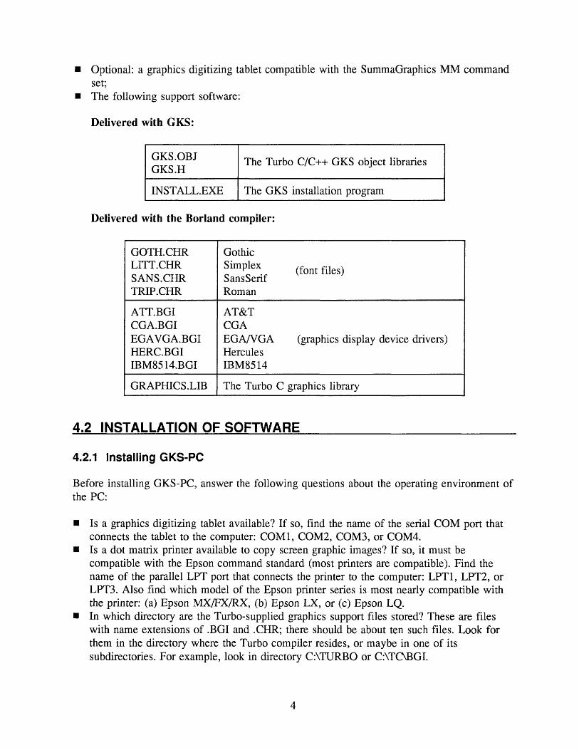
Optional: a graphics digitizing tablet compatible with the SummaGraphics MM commandset;The following support software:
Delivered with GKS:
GKS.OBJ GKS.H
INSTALL.EXE
The Turbo C/C++ GKS object libraries
The GKS installation program
Delivered with the Borland compiler:
GOTH.CHRLITT.CHR SANS.CHRTRIP.CHR
ATT.BGICGA.BGIEGAVGA.BGIHERC.BGIIBM8514.BGI
GRAPHICS.LIB
GothicSimplex (fom files) SansSenfRoman
AT&TCGAEGA/VGA (graphics display deviceHerculesIBM8514
drivers)
The Turbo C graphics library
4.2 INSTALLATION OF SOFTWARE
4.2.1 Installing GKS-PC
Before installing GKS-PC, answer the following questions about the operating environment of the PC:
Is a graphics digitizing tablet available? If so, find the name of the serial COM port that connects the tablet to the computer: COM1, COM2, COM3, or COM4.
Is a dot matrix printer available to copy screen graphic images? If so, it must be compatible with the Epson command standard (most printers are compatible). Find the name of the parallel LPT port that connects the printer to the computer: LPT1, LPT2, or LPT3. Also find which model of the Epson printer series is most nearly compatible with the printer: (a) Epson MX/FX/RX, (b) Epson LX, or (c) Epson LQ.
In which directory are the Turbo-supplied graphics support files stored? These are files with name extensions of .BGI and .CHR; there should be about ten such files. Look for them in the directory where the Turbo compiler resides, or maybe in one of its subdirectories. For example, look in directory C:\TURBO or C:\TC\BGL

Is a RAM-disk utility available on the computer? This is a DOS-supplied program named RAMDRIVE . SYS or VDISK. SYS. Look for it in the root directory or in a system directory like \DOS.
Now proceed with installing GKS.
Insert the issue disk on which GKS-PC was delivered into a diskette drive. Run the GKS install program by typing
disk: INSTALL
For disk, substitute the letter designating the diskette drive containing the GKS issue disk. An example of this command is
A:INSTALL
Follow the directions shown on the screen. Select Install and Configure for the initial installation of GKS (the Configure Only option is explained in 4.2.2 below).
The installation procedure creates a \GKS directory on the destination disk, copies the system into it, then leads through the configuration of GKS to suit the hardware connected to the computer. See the next section.
4.2.2 Configuring GKS-PC
Now the installation program requests entry of the configuration information collected earlier. GKS saves the configuration in a file named GKSC.CFG in the directory \GKS on the destination disk. Thereafter, GKS uses the parameters stored in the configuration file every time GKS is opened by the program. The parameters on the GKS configuration menu are shown in Table 1.
To change the configuration later, just run the INSTALL program again; but select Configure Only instead of Install and Configure.
4.2.3 After Installing/Configuring
If the configuration specifies a virtual RAM disk (i.e., a disk drive higher than the highest actual disk drive on the computer), set up the RAM disk where GKS will store segments during execution of a graphics program. If the configuration specifies segment storage on a real disk drive during the configuration, skip this section.
RAM disk is ideal for segment storage. This is an area of main memory, managed by DOS so it appears to the user like a disk, but it is much faster than a physical disk drive. DOS has a RAM disk driver called RAMDRIVE . SYS (called VDISK. SYS with earlier releases of DOS).
To install RAMDRIVE, add the following line to the CONFIG .SYS file in the root directory on the startup drive (probably C:\):
device - [path] RAMDRIVE.SYS 1024 512 80 /e

Table 1. Configuration parameters.
Parameter Value
Port for graphics tablet
Options are: no tablet connected; serial ports COM1, COM2, COM3, or COM4. Select the correct option. If it is not clear which port is used for the tablet, try COM1. The tablet must be compatible with the SummaGraphics command set and the computer must be 100% BIOS compatible with the IBM standard.
Port for printerOptions are: no printer connected; parallel ports LPT1, LPT2, or LPT3. Select the correct option. If it is not clear which port is used for the printer, try LPT1.
Type of printerThis question appears only if a printer is connected. Options are: Epson compatible (MX/FX/RX, LX, LQ). Select the correct option.
Directory path to Turbo graphics driver files
Enter the complete absolute path to the directory containing the Turbo-supplied .BGI graphics driver files and .CHR character font files. These are usually stored in the same directory where the Turbo compiler is kept. Examples of directory paths are \TC or \BORLANDCXBGI.
RAM disk drive
Enter the letter (A, B, C, ...) of the disk drive where picture segments are to be stored. This should be a RAM disk, if that facility is installed on the computer. If not, it can be a hard disk drive or even a floppy, but these are much slower than RAM disk.
The RAM disk drive identifier is the letter following the last physical disk drive on your system; e.g., if the computer has disk drives A, B, and C, then the RAM disk is drive D.
This creates a RAM disk of 1024 Kbytes (1 Mbyte) with 512 bytes/sector and up to 80 directory entries in extended memory. The optional [path] prefix is the path to the directory where RAMDRIVE . SYS is stored (this is often \DOS\). If the computer doesn't have extended memory (that is, memory above 1 Mbyte), omit the /e. But then RAM disk storage is kept in conventional memory; and this means that 1024 must be replaced by a smaller number, and the RAM disk must share limited memory with the program and its data.
The device command above does not take effect until the computer is restarted. Because GKS programs are likely to exceed 64 Kbytes, the Turbo C or C++ compiler's memory model should be set to Medium when using GKS. Consult the TC manual for the method of doing this; it may have changed with different versions of the compiler. For TC version 2.0, the procedure is: go into TC, bring up the Option menu (ALT-0), then the Compiler submenu, and select Medium under memory model.

4.3 PROGRAM STRUCTURE
4.3.1 Attaching the GKS Library
To use GKS, a program must link to the object library modules containing the graphics routines and device drivers. The GKS library files contain many global declarations that refer to the graphics functions. The program must inherit these declarations from the library.
To attach the GKS libraries to a C program, place the preprocessor command
finclude "\GKS\GKS.H"
near the top of the program. Note, the above backslashes are not doubled as normally is required to avoid C's use of \ as an escape character.
After loading TC, go into the O/C/C menu (Options, Compiler, Code generation)-- or its equivalent in the installed compiler-and toggle the Floating Point setting to read Emulation. This makes the compiled program use the 80x87 numeric coprocessor if one is installed in the computer, otherwise it uses a software emulator to imitate the 80x87. Then the program runs correctly on any computer, whether or not it has the coprocessor hardware. It runs faster with the coprocessor.
The TC compiler's memory model should be set to Medium when using GKS. See page 6 of this document, or consult the TC manual.
For the sake of program compatibility and portability, limit the program to ANSI C syntax only and avoid C++ extensions or special features. Use the suffix . C on the source program file, not .CPP.
4.3.2 GKS Open and Close
Before any graphics plotting functions can be called, the GKS library must be initialized by issuing a call on function Op en GKS. After graphics plotting is finished, GKS must be terminated by a call on CloseGKS. See Appendix 7.5 for an example of OpenGKS and CloseGKS.
Between these two function calls, the program cannot send output to the terminal through printf or put functions; the only allowable terminal activity is generated by GKS itself. If the program includes interaction with the user terminal, it must be done either before calling OpenGKS or after calling CloseGKS; or by using the special input functions provided by GKS: RequestLoc, RequestString, RequestVal, SampleChoice. Input/output operations to external files are permissible while GKS is active; only terminal I/O operations are restricted.
If the program fails to call OpenGKS before calling the graphics plotting functions in section 6 below, GKS writes error messages on the terminal. If the program fails to call CloseGKS after graphics plotting, the terminal remains in graphics mode. Then the behavior of the system is unpredictable; it may require restarting.
Opening GKS uses some space on the runtime free memory list. Opening and closing GKS more than once in a program may use enough additional space to cause memory shortage problems. Normally there is no need to open and close more than once.
4.4 COMPILING
Compiling a GKS program is just like compiling any other C program. But if the #include directive is missing, the compiler produces many error messages because it can't find the information it needs.
The program may be compiled either to memory for immediate execution (assuming there is enough memory heap overflow or malfunction may occur if not), or it may be compiled to disk for stand-alone execution. If the program is compiled to disk, the . BGI and . CHR files (see article 4.1, page 4) still must be available to support the program at run time.
Name the program with the .C suffix, not .CPP; this forces the compiler to use ANSI conventions. To compile a Turbo C++ program using GKS, create & project file containing a script of file and library names that TC uses to compile and link. Consult the language manual. If the program name is MYPROG. C, make a project file named MYPROG. PRJ specifying the source file MYFILE . C and the object library \GKS\GKS . OBJ.
4.5 THE ERROR LOGGING FILE______________________
After GKS becomes active, the system cannot display error messages on the screen because the terminal is in non-ASCII graphics mode. If exceptions occur during execution, GKS writes error messages on an error logging file for review after program termination. The argument of OpenGKS must specify the name of the error logging file; see Appendix 7.5 (page 46) for examples.
After executing the CloseGKS function, GKS displays the error file on the screen if any errors occurred; and it gives the option of copying the error file onto the printer. The error file also can be printed after program termination by the DOS command
PRINT errfile
where err file is replaced by the name of the error file specified in OpenGKS.
While GKS-PC is a subset of the GKS standard, it has additional capabilities not defined by standard GKS. This article describes some differences between GKS-PC and GKS.
5.1 VIEWPORTS________________________________
Since every graphics display adapter for the PC has a unique machine coordinate system, GKS regards all devices as having a display surface described in uniform normalized device coordinates, or NDC. In GKS-PC, the height of the display is described in real coordinates from 0 to 1, and the width in real coordinates from 0 to at least 1. Most displays are wider than they are tall, so GKS-PC allows a drawing rectangle to have a width exceeding 1 unit in order to make use of more of the display surface than standard GKS (which permits a display viewport to have width at most 1). The viewport is the screen area in which graphic drawing

appears. Within GKS-PC the width-to-height ratio (the aspect ratio) varies on different displays, as shown in Table 2.
For program portability, limit the horizontal viewport Table 2. Screen aspect dimension to 1.3. This is within bounds on all the display ratios. modes.
GKS-PC attempts to preserve geometric proportions of Graphics Aspect figures displayed on the screen, so that squares look truly adapter ratio square. However, different manufacturers of graphics CCA 1 adapters and monitors have different ideas of screen AT&T 1 geometry, so a 1-by-l viewport on some screens may not cr^ Ai i AI j- f tUA .be exactly square. Also, some distortion of proportions is Here les 1 479 possible when a dot matrix printer is used to copy a screen VCA 1 333
image " IBM 8514 1.333
5.2 ATTRIBUTES
Attributes are features of the graphics image that govern the appearance of the output, including the texture and color of lines, the shape of marker symbols, or the size of plotted characters. GKS-PC uses individual attributes, by which the properties for each graphics primitive and each display device are either accepted at the default values defined by the system, or they are explicitly set to other values using separate calls on the attribute setting functions described in section 6.3 (page 14). Standard GKS provides for setting a large bundle of attributes at once using a single function call, but GKS-PC does not use this approach.
5.3 FUNCTION NAMES AND ARGUMENTS______________
Standard GKS defines some functions with long names, for example "Select Normalization Transformation." In GKS-PC, function names are abbreviated for convenience while preserving the descriptive value of identifiers. The above function in GKS-PC is called SelectNormTrans.
Some GKS-PC functions have argument lists that differ slightly from those defined in the GKS standard. These variances simplify or clarify the passing of arguments to functions.
5.4 WORKSTATIONS______________________________
GKS defines a workstation as a graphics input or output device. It may be a CRT terminal, plotter, printer, keyboard, digitizing tablet, or several interconnected graphics input or output devices. Under standard GKS a program can define and activate several workstations at once and separately manage the activity on each of them; a flexible but complicated idea. GKS-PC uses a simpler workstation management method: the configuration procedure mentioned in article 4.2.2 (page 5) predefines workstation parameters and activates the workstation each time a program opens GKS.

5.5 PRINTED OUTPUT
Whenever the program pauses during graphics drawing (on a call to function Pause), GKS waits while the user views the image.
During the pause, GKS gives an option to send the picture currently on the screen to an Epson-compatible graphics printer, if the computer has one. There are two ways of printing the image: using the GKS built-in printer driver, or using the Shift-PrtScr command. Experiment with both to find the best results.
With either method, the screen print routines assume that the printer uses continuous forms. If it has single page feed, some screen images may not fit on a page before the printer gives a paper-out alarm. Then the rest of the image is printed on the next page. Use legal sized paper to get the entire picture on one page.
5.5.1 The GKS Printer Driver
When the program pauses, press the P key (or enter CTRL-P) to start the printer. GKS selects the best printer density for the video mode and printer in the workstation configuration.
To experiment with different print densities, press one of the digit keys 1... 7 or one of the letter keys A. . . G instead of P to start the printer. The digit keys print the image horizontally across the page; the letter keys print it vertically down the page. Each key selects a different printer horizontal resolution; try the seven different modes to find the desired combination for the CRT and printer.
The output of the built-in driver is a one-to-one mapping of pixels in the CRT's bit map into dots in the printer's matrix, and uses only the 9-pin mode of a dot matrix printer, even if the printer has 24 pins. The printer must be graphics compatible with one of the standard printer types on the configuration menu (see Table 1, page 6). This method works with all the graphics adapters supported by GKS, but there may be some distortion of proportions if the pixel ratio of the CRT differs from the dot ratio of the printer.
To abort the screen print after it has started, press any printing key on the keyboard.
5.5.2 The Shift-PrtScr Command
This uses a resident utility program named GRAPHICS . COM that comes with DOS. It may give better results than the GKS printer driver with some graphics adapters or printers, but may fail to work at all with some others.
To use this method, load the GRAPHICS program before starting the GKS run, unless it is already loaded. Enter the DOS command
GRAPHICS
This command loads the resident screen dump utility, then returns to the DOS prompt. When GKS pauses at a call on function Pause, start the printer with the key code Shift- PrtScr (hold down on the Shift key while pressing the key labelled PrtScr, or PrtSc, or PrtScrn).
10

The GRAPHICS utility included with later versions of MS-DOS is improved over earlier releases. It can handle CGA, EGA, and VGA screens and a variety of printer types, including Hewlett-Packard LaserJet and DeskJet models. Consult the MS-DOS manual.
6. THE GKS LIBRARY FUNCTIONS
The rest of this document describes in detail each function contained in the GKS library for performing graphics functions. Function names must be written with the exact capitalization shown below, as the C programming language is case sensitive. All routines are called as procedures (none returns a function value), and arguments are passed by value instead of by pointer except as noted in the section on graphics input (page 36).
The GKS environment has predefined several words used in communicating arguments to some library functions: words like Center, Simplex, Red, Dotted. A complete list of these keywords is in article 7.3, page 44. These are not reserved words; i.e., the Turbo compiler does not prevent the user program from redefining any of them. Be careful not to declare a predefined word as a program constant or variable, as the user's value overrides the GKS predefined value, and the GKS system probably will malfunction in some way because the environment of the library functions is modified.
All the predefined words are named integer constants. To pass a predefined word as an argument into a user-written function, declare it as an integer.
6.1 ENTRY AND EXIT FUNCTIONS__________________
6.1.1 OpenGKS
This function activates GKS and initializes its internal variables, preparing the system to produce graphics output. No calls to any other GKS functions should be attempted before calling OpenGKS. After the program calls OpenGKS, all writing to the screen is in graphics mode; therefore the program cannot attempt to produce any other output directed to the screen through printf or puts functions, until after calling CloseGKS (see 6.1.2 below).
OpenGKS ( errfile )
errfileis replaced by the quoted name of a file on which GKS writes its error messages, if any errors occur. A character string variable also can be used for errfile.
Be sure to use a legal DOS file name (including a directory prefix if necessary), as GKS doesn't check the legality of the name, and an incorrect file name causes unpredictable results. An example of a call on OpenGKS is
OpenGKS ( "\\MAPS\\MEXICO.ERR" );
11

The double \\ in the C path string forces the C compiler to accept a single backslash character. Backslash is C's escape character, which normally gives special meaning to the following character.
6.1.2 CloseGKS
This function deactivates GKS, returning the terminal to normal ASCII mode. CloseGKS takes no arguments:
CloseGKS ()
Consider preceding CloseGKS with a call on Pause to allow viewing the final image before exiting from graphics mode. See Pause on page 32. When it receives the command to continue, CloseGKS clears the graphic image and returns the system to normal ASCII operation.
CloseGKS cannot be called while a segment is open, otherwise GKS issues an error.
6.2 WINDOWING FUNCTIONS________________________
A window is a rectangular area of interest in the real world coordinate system containing the user's application data. A window is defined in terms of user's real world coordinates (WC).
A viewport is a rectangular area on the display surface of the graphical viewing device. A viewport is defined in terms of real normalized device coordinates (NDC), previously defined on page 8. Once a window and a viewport are declared and selected, the interior of the specified window is associated with the rectangular viewport on the terminal screen so that any drawing done in the virtual world window maps onto a corresponding image in the viewport, which is in turn mapped onto the physical display surface.
Taken together, the world window dimensions and the viewport dimensions define a normalization transformation. A normalization transformation takes effect when it is selected by a call on SelectNormTrans (page 14). A program can define up to 64 different normalization transformations (numbered 1 to 64) at a time, and any one of these can be in use at any time. GKS internally defines one additional normalization transformation (number 0); it maps the unit square in world coordinates onto the unit square in normalized device coordinates. It cannot be changed by the user program, and it is the default transformation used by GKS if the program doesn't select another.
6.2.1 SetWindow
This function specifies dimensions of a world window and attaches this window to a specified normalization transformation. SetWindow doesn't select this transformation for use; that is done by function SelectNormTrans (page 14).
SetWindow
nt is replaced number in
( nt, xlow, xhigh, ylow, yhigh )
by the
an integer range 1 to
normalization 64.
transformation
12

xlow, xhigh
ylow, yhigh
are replaced by real values defining the extent of the window horizontally, in world coordinates, with constraint
xlow < xhigh
are replaced by real values defining the extent of the window vertically, in world coordinates, with constraint
ylow < yhigh
An example of Set Window is
SetWindow ( 3, -476.4, 539.0, -12.08, 9.16 );
The default for any normalization transformation window not explicitly set otherwise is xlow = 0.0, xhigh = 1.0, ylow = 0.0, yhigh = 1.0.
6.2.2 SetViewport
This function specifies a rectangular area on the graphics display surface into which the virtual drawing done in the world window will be projected, and attaches this viewport to a specified normalization transformation. SetViewport doesn't select this transformation for use; that is done by function SelectNormTrans (page 14).
SetViewport ( nt, xlow, xhigh, ylow, yhigh )
nt
xlow, xhigh
ylow, yhigh
is replaced by an integer normalization transformation number in the range 1 to 64.
are replaced by real values defining the extent of the viewport horizontally, in NDC, with constraints:
0.0 < xlow < xhigh < 1.3 The upper limit 1.3 is within bounds for all graphics video displays; see Table 2, page 9.
are replaced by real values defining the extent of the viewport vertically, in NDC, with constraints:
0.0 <ylow < yhigh < 1.0
An example of SetViewport is
SetViewport ( 3, 0.1, 0.9, 0.0, 0.75 );
The default for any normalization transformation viewport not explicitly set otherwise is xlow = 0.0, xhigh = 1.0, ylow = 0.0, yhigh = 1.0.
13

6.2.3 SelectNormTrans
This function selects one of the normalization transformations previously defined by calls on SetWindow and SetViewport, and makes it the transformation in effect for future drawing primitives. It remains active until another call is made on SelectNormTrans.
SelectNormTrans ( nt )
is replaced by the number of the normalization transformation to be selected, in the range 0 to 64.
An example of SelectNormTrans is
SelectNormTrans (3);
The default normalization transformation is number 0; see page 12. GKS uses this until the user selects another.
The windowing and viewport settings of the currently selected normalization transformation can be changed by calls on SetWindow or SetViewport, but this is not recommended since it may interfere with correct operation of segment transformations. In any case the changed window/viewport settings do not take effect unless the program makes a new call on SelectNormTrans.
6.3 ATTRIBUTE SETTING FUNCTIONS_______________
If attributes are not explicitly set before calling on the functions that produce graphical output, then GKS uses its default attributes. The attribute functions do not cause any graphical output to be produced. Actual figure drawing is done by the functions in article 6.4, page 24.
Arguments for some of these functions are chosen from a restricted set of possibilities. In these cases the GKS environment has already assigned these possible values to predefined identifiers, to make function calling more intuitive. Thus for example, to specify that lines are to be drawn in a dotted texture, write SetLineType (Dotted) instead of something cryptic like SetLineType (3). The identifier Dotted is an example of a predefined word. Predefined words are constant identifiers, not character strings, so they are not enclosed in quotes.
6.3.1 SetLineType
This function sets GKS to draw all lines (including the lines used to make Stroke or Italic characters) in a selected texture or line style. The possible line types are:
Solid Dashed Dotted DashDot
The selected line type remains in effect until another call on SetLineType changes it.
14

SetLineType (
type is replaced by one of the
type
four
)
line types above.
An example of SetLineType is
SetLineType (DashDot);
The default line type is Solid.The four line types are predefined identifiers in the GKS environment, and they should
not be redefined.
6.3.2 SetLineWidth
This function sets GKS to draw all lines (including the lines used to draw Stroke or Italic characters) in a selected line thickness. The possible line widths are:
Thick Thin
The selected line width remains in effect until another call on SetLineWidth changes it.
SetLineWidth (
thickness is replaced by one
thickness )
of the two line widths above.
An example of SetLineWidth is
SetLineWidth (Thick);
The default line width is Thin. Thick lines drawn at the screen display boundaries may not be as thick as lines drawn in the interior of the display space.
The two line widths are predefined identifiers in the GKS environment, and they should not be redefined.
6.3.3 SetMarkerType
This function sets GKS to plot markers in a selected style or shape. The possible marker types are:
Square Cross Plus Circle Triangle Dot
The selected marker type remains in effect until another call on SetMarkerType changes it. Samples of the six marker types are shown in Figure 2.
15

X.
B""" w """-4.""""' ,S> fcb o ~ o ti
g ^ w .fa .S "o tf ^ o £ Q2 PH
CO
Figure 2. Marker types.
SetMarkerType (
type is replaced by one of the
type )marker types above.
An example of SetMarkerType is
SetMarkerType (Circle);
The default marker type is Square .The six marker types are predefined identifiers in the GKS environment, and they should
not be redefined.
6.3.4 SetClipInd
This function determines whether GKS clips drawings at the current window boundary:
SetClipInd ( ind )
ind is replaced by one of the two clipping indicators Clip or NoClip.
An example of this function call is
SetClipInd (NoClip);
The default clipping indicator is Clip.The setting of the clipping indicator affects all graphical output primitives: lines, markers,
text, and area fill; but its behavior with text output depends on the selected font. For most fonts, characters are clipped at the window boundary just as vectors would be, so a character that lies partly inside the clipping window is partly visible. But if the font is Standard (see 6.3.5 following), character cell clipping is used: this means that if any part of a character lies outside the clipping window, then none of that character is visible in the image.
The words Clip and NoClip are predefined identifiers in the GKS environment, and they should not be redefined.
16

6.3.5 SetTextFont
This function selects the style of characters used to plot text. The possible fonts are:
This is a simple type face made of a few vector strokes, but it is the highest precision font in GKS-PC. Stroke characters can be produced in any size and with a base line at any angle to the horizontal. It is also the only font that can be italicized, and the only one that can be reflected vertically or horizontally (see page 34). Stroke is a monospaced font: every character occupies the same horizontal space.
Stroke
Italic This is the italic variant of Stroke.
This is a low precision bit mapped type face similar to that used to produce screen characters in ASCII mode. It is attractive for making small characters, but the font is enlarged by pixel replication so in larger sizes Standard characters look crude. The aspect ratio of Standard characters is not variable, and both the largest and smallest character sizes are limited. Standard is a monospaced font.
Standard
This is a medium resolution font made of a few vector strokes. It is attractive Simplex and legible in all sizes. It is not quite monospaced: a few characters are
narrower than the others.
This is more ornate than Simplex, approximating the type face used in book Roman printing. It looks best in larger sizes. It is proportionally spaced: each
character has its own horizontal spacing value.
SansSerif
Gothic
This font is bolder than Simplex but less ornate than Roman and looks good in most sizes. Proportionally spaced.
Gothic is... well, Gothic. It's hard to read unless it is of a larger size. Proportionally spaced.
Examples of these fonts are in Figure 3.
SetTextFont (font)
font is replaced face to be
by the used in
name of plotting
the text
type
An example of SetTextFont is
SetTextFont (Simplex);
The default font is Stroke.
17

5 t r D k E Roman
SansSerif
Simplex
StandardFigure 3. Text fonts.
6.3.6 SetCharHeight
This function determines the height of characters produced by the Text function described in 6.4.5, page 26.
SetCharHeight ( height )
height is replaced by a positive real number, desired characters in world units. The
the height of the height must be > 0.
An example of SetCharHeight is
SetCharHeight (1.25);
The default character height is 0.05 world units, but the height must be changed to something more appropriate if the world window differs much from the unit square. Because of variations between different fonts, character height renderings may be approximate.
Setting the character height also determines the width, as GKS proportions all character cells with width equal to some fraction of the height. The relation of height to width depends on the choice of font. But the normalization and segment transformations (see page 12 and page 28), and the function SetCharExpFact (page 21), may modify these proportions.
6.3.7 SetCharUpVect
This function determines the angle of the base line along which characters are plotted by function Text. It does this by specifying the components of an up-vector that points from the base line of the character cell toward the top of the character. Only the high precision fonts Stroke and Italic can be tilted to any angle; all the others can be displayed only with a horizontal base line (up vector (0, 1)), or with a vertical base line (up vector (-1, 0)). These other fonts respond to any other up-vector by assuming a horizontal base line.
18

SetCharUpVect ( upx,
upx
upy
is replaced
is replaced
by
by
the
the
^-component
^-component
of
of
upy
the
the
)
desired up-vector;
up-vector.
An example of SetCharUpVect is
SetCharUpVect ( -0.5, 0.9 );
The magnitudes of upx and upy are not important, provided their ratio gives the correct slope for the up-vector. The up-vector must have positive length. The default up-vector is (0, 1), which plots characters along a horizontal base line.
Only the high precision fonts Stroke and Italic can be tilted to any angle; all the others can be displayed only with a horizontal base line (up vector (0, 1)), or with a vertical base line (up vector (-1, 0)). These other fonts respond to any other up-vector by assuming a horizontal base line.
If strings are plotted with the text path set to Right (see SetTextPath following), then the character up-vector is perpendicular to the path of the text string. If strings are plotted with the text path set to Down, then the character up-vector is parallel to the path of the text string, and directed toward the top of the text box.
6.3.8 SetTextAlign
This function determines the way in which the box surrounding a string of plotted text positions itself with respect to the alignment point given in a call on function Text (page 26).
SetTextAlign ( horiz, vert)
horiz
vert
is replaced by the desired horizontal alignment point, with possible values
Left Center Right
is replaced by the desired vertical alignment point, with possible values
Bottom Base Half Cap Top
These two arguments combine to give 15 different alignment points, as shown in Figure 4. An example of SetTextAlign is
SetTextAlign ( Center, Half );
The default alignment point is (Left, Base). Because of variations between fonts, text alignment renderings may be approximate.
19

-j^ TOP
4 CAP
LEFT CENTER
HALF
BASE - BOTTOM
RIGHT
Text Alignment
Vertical
Horizontal
TOP CAP HALF BASE BOTTOM
LEFT CENTER RIGHT
TOP CAP
HALF
I I BASE
-* --* BOTTOM
LEFT
Figure 4. Text alignments.
CENTER RIGHT
The eight alignment words shown above are predefined identifiers in the GKS environment, and they should not be redefined.
6.3.9 SetTextPath
This function selects the direction of the imaginary line joining the character cells to be plotted. There are two possible paths (see Figure 4).
Right in which each character is to the right of its predecessor along a path perpendicular to the character up-vector;
Down in which each character is below its predecessor along a path parallel to the character up-vector.
SetTextPath ( path )
path is replaced by either Right or Down.
20

An example of SetTextPath is
SetTextPath (Down);
The default path is Right. The words Right and Down are predefined identifiers in the GKS environment, and they should not be redefined.
6.3.10 SetCharExpFact
Every font defines its own character width as a ratio of the character height. This function sets the character expansion factor to a value different from that inherent in the font.
SetCharExpFact (factor )
factoris a positive real number expressing the degree of horizontal expansion or contraction of characters, relative to the font's default character width.
An example of SetCharExpFact is
SetCharExpFact (1.4);
Values of factor greater than 1 stretch characters horizontally by that expansion factor; values less than 1 contract characters horizontally by that factor. The default value of factor is 1.
This function is useful when plotting text with a normalization transformation that maps a world window into a viewport with a significantly different aspect ratio. Such a normalization transformation deforms the characters by horizontal stretching or contraction (for fonts other than Standard). If this is undesirable, the default proportions of characters can be main tained by a call on SetCharExpFact with the argument
factor = (HV*WW)/(HW*WV)
where WV = width of viewport HV = height of viewport WW = width of window HW = height of window
The expansion factor of the Standard font cannot be modified, and it ignores a call on the SetCharExpFact function.
6.3.11 SetFillStyle
This function selects the pattern to be used by function FillArea (page 28) in filling the interior of a polygon. Several fill styles are possible, as listed on page 23 and illustrated in Figure 5.
21

Hoilou
Solid
S lat
to
to
Corduroy
Grid
Hatch
Fabric
SparseDot
DenseDot
Fig
ure
5. F
ill s
tyle
s.
Hollow Corduroy
Solid Grid
Slat Hatch
Light45 Fabric
Heavy45 SparseDot
Heavyl35 DenseDot
SetFillStyle ( style )
style is replaced by one of the filling styles above.
An example of SetFillStyle is
SetFillStyle (Grid);
Filling a polygon also implies drawing its border.The default filling style is Hollow. It differs from the PolyLine primitive in two ways:
a hollow-filled polygon is considered closed, even if the starting and ending vertices differ; and the interior of a hollow-filled polygon is actually erased, obliterating anything that was already present there. Refer to 6.4.2, page 25, and 6.4.6, page 28.
The twelve filling styles are predefined identifiers in the GKS environment, and they should not be redefined.
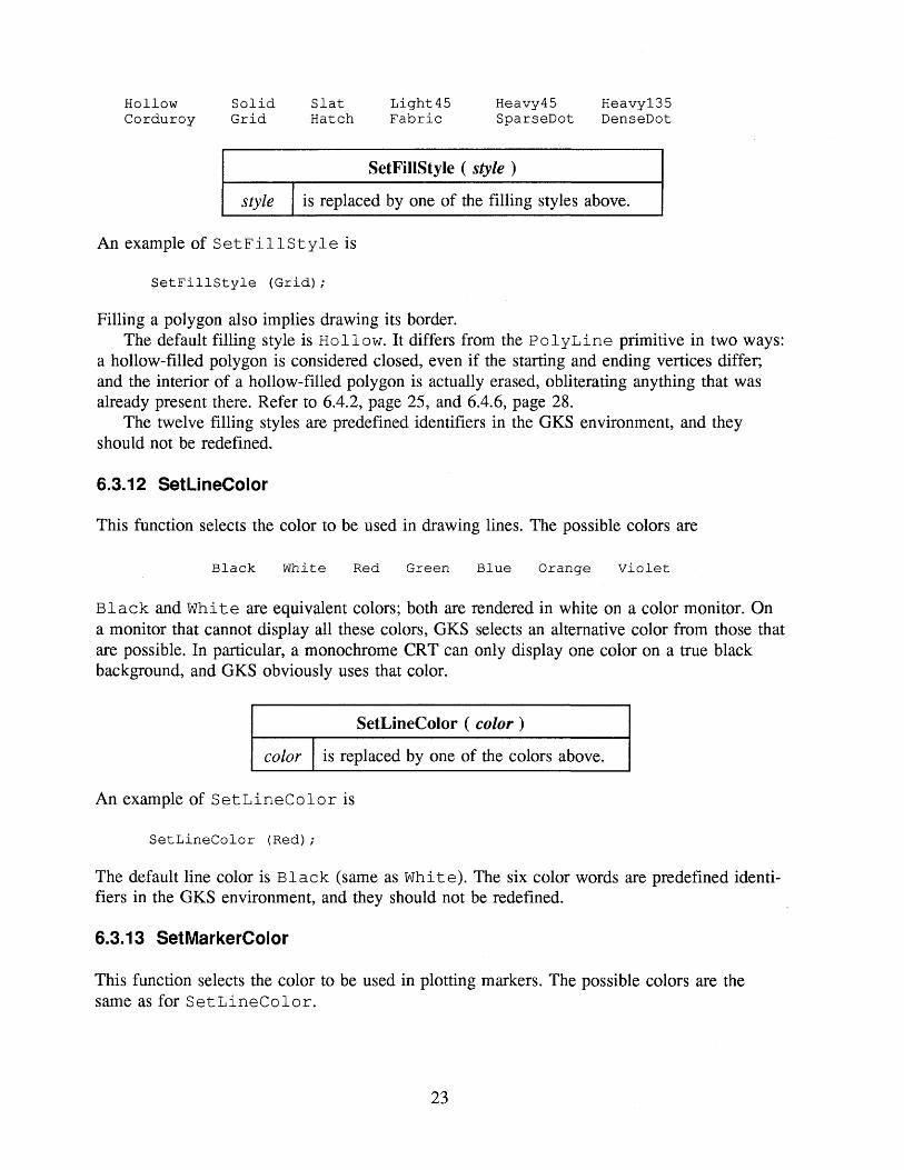
6.3.12 SetLineColor
This function selects the color to be used in drawing lines. The possible colors are
Black White Red Green Blue Orange Violet
Black and White are equivalent colors; both are rendered in white on a color monitor. On a monitor that cannot display all these colors, GKS selects an alternative color from those that are possible. In particular, a monochrome CRT can only display one color on a true black background, and GKS obviously uses that color.
SetLineColor
color is replaced by one
( color )
of the colors above.
An example of SetLineColor is
SetLineColor (Red);
The default line color is Black (same as White). The six color words are predefined identi fiers in the GKS environment, and they should not be redefined.
6.3.13 SetMarkerColor
This function selects the color to be used in plotting markers. The possible colors are the same as for SetLineColor.
23

SetMarkerColor (
color is replaced by one of the six
color )
colors defined in 6.3.12.
An example of SetMarkerColor is
SetMarkerColor (Green);
The default marker color is Red.
6.3.14 SetFillColor
This function selects the color to be used in filling the interiors of polygons. The possible colors are the same as for SetLineColor.
SetFillColor ( color )
color is replaced by one of the six colors defined in 6.3.12, page 23.
An example of SetFillColor is
SetFillColor (Violet);
The default fill color is Blue.
6.3.15 SetTextColor
This function selects the color to be used in displaying text. The possible colors are the same as for SetLineColor.
SetTextColor ( color )
color is replaced by one of the six colors defined in 6.3.12, page 23.
An example of SetTextColor is
SetTextColor (Red);
The default text color is Green.
6.4 DRAWING PRIMITIVES
The drawing primitives of GKS are lines, markers, text, and area fill.
24

6.4.1 Line
This function draws a single line segment between the display coordinates corresponding to any two points in the world coordinate system.
Line ( xl, yl, x2, y2 )
xl.yl
x2, y2
is replaced by the location of the starting point of the vector in world coordinates;
is replaced by the location of the ending point of the vector in world coordinates.
An example of Line is
Line ( -3.4, -0.6, 4.67, 8.03 );
The line is drawn in the default line type and color, or with other attributes selected by SetLineType and SetLineColor.
The Line function is not defined in the GKS standard. GKS-PC includes it because it is more convenient than PolyLine (below) for drawing single vectors.
6.4.2 PolyLine
This function uses straight line segments to connect all the consecutive pairs of vertices in a polygon specified by the content of two one-dimensional arrays; one array for the x- coordinates and the other for the ^-coordinates.
PolyLine ( nv,
nv
xarray
yarray
xarray, yarray )
is replaced by the integer number of vertices. A polyline may have at most 8191 vertices.
is replaced by the real x-coordinates
is replaced by the real y-coordinates
name of an array in world space;
name of an array in world space.
containing
containing
The polyline is drawn in the default line type and color, or with other attributes selected by prior calls on SetLineType and SetLineColor.
Note, PolyLine does not produce a closed polygon unless the last vertex coincides with the first.
25

6.4.3 Marker
This function draws a single marker symbol at the display coordinates corresponding to any point in the world coordinate system. A marker is a small symbol (square, circle, triangle, etc.) centered over the plotted point.
Marker
x,y is replaced coordinates
by the where
(x, y}location of the marker
the point in real is to be placed.
world
The marker is plotted in the default marker shape and color, or with other attributes selected by prior calls on SetMarkerType and SetMarkerColor.
The Marker function is not defined in the GKS standard. GKS-PC includes it because it is more convenient than PolyMarker (below) for drawing single markers.
6.4.4 PolyMarker
This function uses marker symbols to plot the locations of the vertices in a polygon specified by the content of two one-dimensional arrays; one array for the jc-coordinates and the other for the y-coordinates. The vertices are not connected by vectors.
PolyMarker ( nv, xarray, y array )
nv
xarray
yarray
is replaced by the integer number of vertices. There can be no more than 8192 vertices.
is replaced by the name of an array containing real jc-coordinates in world space.
is replaced by the name of an array containing real y-coordinates in world space.
The markers are plotted in the default marker shape and color, or with other attributes selected by prior calls on SetMarkerType and SetMarkerColor.
6.4.5 Text
This function plots a given text string on the graphics display at a given alignment point in world coordinates.
Text ( xalign, yalign, string )
xalign, yalign is replaced by the location (in world of the point where the string is to be
coordinates) aligned.
26
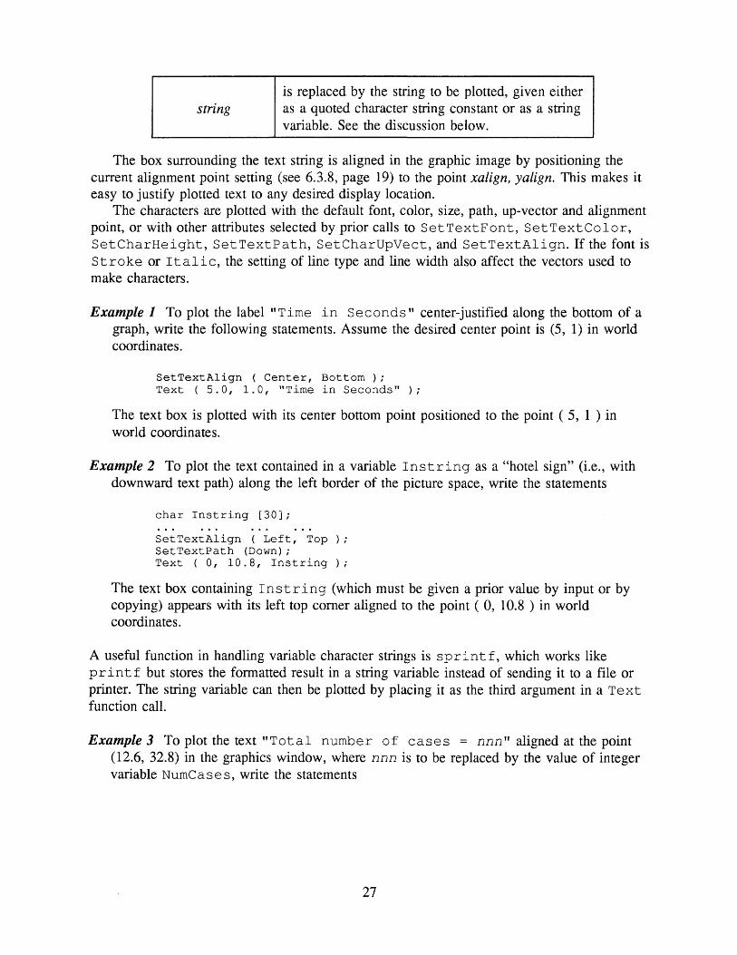
stringis replaced by the string to be plotted, given either as a quoted character string constant or as a string variable. See the discussion below.
The box surrounding the text string is aligned in the graphic image by positioning the current alignment point setting (see 6.3.8, page 19) to the point xalign, yalign. This makes it easy to justify plotted text to any desired display location.
The characters are plotted with the default font, color, size, path, up-vector and alignment point, or with other attributes selected by prior calls to SetTextFont, SetTextColor, SetCharHeight, SetTextPath, SetCharUpVect, and SetTextAlign. If the font is Stroke or Italic, the setting of line type and line width also affect the vectors used to make characters.
Example 1 To plot the label "Time in Seconds" center-justified along the bottom of a graph, write the following statements. Assume the desired center point is (5, 1) in world coordinates.
SetTextAlign ( Center, Bottom ); Text ( 5.0, 1.0, "Time in Seconds" );
The text box is plotted with its center bottom point positioned to the point (5, 1 ) in world coordinates.
Example 2 To plot the text contained in a variable Instring as a "hotel sign" (i.e., with downward text path) along the left border of the picture space, write the statements
char Instring [30];
SetTextAlign ( Left, Top );SetTextPath (Down);Text { 0, 10.8, Instring )/
The text box containing Instring (which must be given a prior value by input or by copying) appears with its left top corner aligned to the point ( 0, 10.8 ) in world coordinates.
A useful function in handling variable character strings is sprintf, which works like printf but stores the formatted result in a string variable instead of sending it to a file or printer. The string variable can then be plotted by placing it as the third argument in a Text function call.
Examples To plot the text "Total number of cases = nnn" aligned at the point (12.6, 32.8) in the graphics window, where nnn is to be replaced by the value of integer variable NumCases, write the statements
27

int NumCases; char Heading [30];
sprintf ( Heading, "Total number of cases = %3d", NumCases ) Text ( 12.6, 32.8, Heading );
6.4.6 FillArea
This function fills the interior of a closed polygon with a selected pattern.
FillArea ( nv, xarray, yarray )
nv
xarray, yarray
is replaced by the integer polygon. There can be no
number of vertices in the more than 8192 vertices.
are replaced by the names of real arrays containing the polygon vertices in world coordinates.
If the polygon is not closed, i.e., if the last vertex in arrays xarray and yarray does not coincide with the first vertex, then FillArea closes the polygon by assuming a temporary extra edge connecting the last vertex with the first during the filling process; but it doesn't alter nv or the content of arrays xarray or yarray.
Filling is in the default style and color, or with other attributes selected by SetFillStyle and SetFillColor.
6.5 SEGMENT FUNCTIONS_________________________
A segment is a collection of graphic primitives that are stored and transformed in certain ways as a unit, independently of other segments. The program may define up to 64 different segments (numbered 1 through 64) containing output primitives. Segments may be created, filled with graphic output information, transformed by scaling, rotating or translating, made visible or invisible, and optionally deleted. Any number of the 64 segments may be defined and visible simultaneously.
Segment transformation affects all four drawing primitives: lines, markers, text, and area fill. But note the following variances:
Marker size and orientation are not affected by segment transformation. Markers can only be moved to a new location by translation, scaling, or rotation.
The patterns used to fill closed polygon areas are not affected by segment transformation. The fill pattern always has a fixed grid size and orientation. But the polyline that defines the boundary of the area to be filled is affected by all segment transformations.
Only the Stroke or Italic fonts have an unlimited range of scaling. The other fonts have both a maximum and minimum size. Text can be rotated to any baseline angle only for Stroke or Italic fonts; the other fonts ignore segment rotation. Note that segment rotation of text is separate from, and in addition to, the text direction established by the character up-vector.
28

Segments contain only output information and the attribute settings that govern the output. Pause, ClearWS, CloseGKS, and CreateSeg cannot be used while a segment is open. Other functions may be called while a segment is open, but only calls to functions that produce graphical output contribute to the content of the segment database.
Certain operations on segments, such as turning the visibility off or modifying the appearance of the segment by applying a transformation to it, imply that portions of the view are erased selectively while leaving the rest of the image alone. Erasing a segment may leave holes in other visible segments, but GKS has a function (RedrawAllSeg, page 32) for refreshing the screen to restore the visible image. There is a manual keyboard command for doing the same thing during a call on Pause in picture drawing (see page 32).
The purpose of segments is to permit parts of the image to be modified. The normalization transformation that is in effect when the segment is created also must be current when the segment is transformed; thus, the parameters of the normalization transformation used to create the segment should not be modified before the segment transformation is computed. Further, if a segment is to be transformed, then the normalization transformation should not be changed in the midst of generating the segment content. See the discussion of segment transformation in 6.5.5 (page 31) and in 6.7 (page 33).
6.5.1 CreateSeg
This function creates a new segment and prepares it to be filled with graphic plotting data.
CreateSeg (
seg is of
replaced by the segment
the to
seg)
identifying be created.
number
An example of CreateSeg is
CreateSeg (15);
Segment numbers are in the range 1 to 64. The segment to be created must not already exist, and no other segment can be currently open when CreateSeg is called. On creation, a segment inherits the current settings of all graphical attributes; but these attributes may be changed while filling the segment with output primitives.
Segments should be created and numbered in the order they should be painted onto the screen. Particularly when filling areas in overlapping segments, the program can control which objects overlay and obscure others. Even then, switching segment visibility off and on can upset the priority of segment display. Then, a call on RedrawAllSeg (page 32) or the R keyboard command at a call on Pause (page 32) restores proper segment priority.
A visible segment is not displayed until it is closed. Thus if a program creates a large segment, there could be a noticeable delay before the segment's image appears on the screen.
6.5.2 CloseSeg
This function closes the currently open segment; no further primitives can then be placed in that segment, and it cannot be reopened thereafter. If no segment is open, a call on
29

CloseSeg generates an error. The function requires no arguments, since only one segment can be open at a time:
CioseSeg ()
6.5.3 DeleteSeg
This function deletes a specified segment from the list of created segments.
seg is replaced by
DeleteSeg
the number
( seg )
of the segment to be deleted.
Segment number seg must be created earlier and then closed, else an error results. The portion of the graphic view belonging to the specified segment is erased from the display. The number seg can then be reused to create another segment.
An example of DeleteSeg is
DeleteSeg (2);
6.5.4 SetVis
This function sets the visibility attribute of a specified segment. The portion of the view belonging to a segment can be switched off without destroying the content of the segment, and it can later be made visible again. The possible values of the visibility attribute are
Visible Invisible
Set Vis ( seg, vis )
seg is replaced by the number of the segment to be made visible or invisible;
vis is replaced by one of the above two visibility attributes.
An example of SetVis is
SetVis ( 5, Invisible );
The specified segment must have been created previously. The default visibility for any segment at the time of its creation is visible, but the visibility of a segment can be changed at any time after that; either while the segment is open or after it is closed.
The words Visible and Invisible are predefined identifiers in the GKS envi ronment, and they should not be redefined.
30

6.5.5 SetSegTrans
If a suitable transformation matrix has been generated (see below), this function attaches the matrix to a specified segment, and the display of the segment is modified accordingly. The current segment is erased from the view and is then redrawn as modified by the new transformation. The order of applying the transformations is: scale, rotate, translate.
SetSegTrans ( seg, matrix )
seg
matrix
is
is
replaced
replaced
by
by
the
the
number
name of
of
a
the
2x3
segment to be transformed;
real transformation matrix.
The argument matrix must be declared in the type float [ 2 ] [ 3 ]. The content of the matrix may be generated directly by the program before calling SetSegTrans, or it may be created more conveniently by a call on the utility function EvalTransMat (page 33).
SetSegTrans applies a new transformation matrix to the content of the segment as it was created originally. It does not accumulate the new transformation with some previous transformation of the segment. To make segment transformations accumulate, explicitly call AccumTransMat (page 35). Thus applying a transformation matrix to a segment does not alter the content of the segment, it only displays a transformed view of it.
Note that it is not necessary to use SetVis to control visibility of the segment being transformed. The call to SetSegTrans is enough by itself; it takes care of turning the segment image off, transforming it, and turning it back on.
The default transformation assigned to every segment at the time of its creation is the identity transformation (no translation, no rotation, and unit scale factors). The segment transformation may be changed by the program to something else. Later, to return to the identity transformation, call the function
SetSegTrans ( seg, Ident ) ;
where seg is the number of the segment and Ident is the predefined name of an identity transformation matrix.
6.5.6 RenameSeg
This function can be used to change the identifying number of a segment.
RenameSeg (
old
new
is replaced
is replaced
by
by
the
the
existing
new
old, new )
number of the
number to be
segment.
given to the segment.
Segment number old can then be reused to create a new segment. Segment old must already exist, and segment new must not be already in use; else GKS issues errors.
31

An example of Re names eg is
RenameSeg ( 2, 5 ) ;
6.5.7 RedrawAIISeg
This function refreshes the screen by redrawing all currently visible segments. It is useful when transformations have changed the image, and modifying one or more segments has left holes in other parts of the image. RedrawAIISeg is the programmatic equivalent of the R keyboard command mentioned in the discussion of Pause in section 6.6.1.
RedrawAIISeg ()
It is an error to call RedrawAIISeg while a segment is still open.
6.6 CONTROL FUNCTIONS_________________________
6.6.1 Pause
This causes the program to wait while the operator views the display and optionally gives a command to refresh or print the image on the screen. Pause is not a standard GKS function.
Pause ()
At a call on Pause, GKS waits for the user to view the image. During the pause, it gives several options: to send the image to a printer, to refresh the picture on the screen, to abort the program, or to continue to the next part of the program. There are two ways of printing the image: using the GKS built-in printer driver, or using the Shift-PrtScr command. These are discussed on page 10.
Following are the key commands accepted by Pause:
PP
CTRL-P1 ...7 a... g
(Print) Any of these keys copy the current screen image to an Epson graphics compatible printer. The response of other printers is not guaranteed. See the comments in 5.5.1, page 10.
Rr
CTRL-R
(Refresh) Any of these keys refresh the screen by redrawing all currently visible segments. This is useful when transformations have changed the image, and modifying one or more segments has left holes in portions belonging to other segments. See also RedrawAIISeg in the preceding article.
32

CTRL-C
(Abort) This key command causes the GKS run to be aborted and the system returned to text mode operation. Note that CTRL-C only works during a pause in the program. It does not interrupt the program during generation of a graphics image.
To resume execution of the program, press Return.The printed image produced by the P key or 1...7 or a...g keys has proportions dependent
on the printer and the display adapter, and may not be shaped exactly like the screen image.Pause cannot be called while a segment is open, otherwise GKS issues an error.
6.6.2 ClearWS
This function clears the display space of the workstation and prepares it to receive a new view:
ClearWS ()
Consider preceding ClearWS with a call on Pause to allow time to view the final image before the screen is erased. See Pause on page 32. At the command to continue, ClearWS clears the graphic image and prepares to generate the next view.
ClearWS not only clears the screen, it also deletes all current segments. It does not clear the internally set attribute list. It cannot be called while a segment is open, otherwise GKS issues an error.
6.7 UTILITY FUNCTIONS____________________________
6.7.1 EvalTransMat
This function creates the entries for a segment transformation matrix from parameters for translation, rotation, and scaling:
EvalTransMat ( /#, fy, tx, ty, ang, sx, sy, switch, mat )
fafy
tx, ty
These are replaced by the real coordinates of a fixed point, which is the center of the rotation and scaling transformations (see below). The fixed point is in either world coordinates or normalized device coordinates, depending on the setting of the switch argument (see below). The fixed point has no bearing on translations.
These are replaced by real translations in the directions of x and y respectively. They are expressed in either world or normalized device coordinates, depending on the setting of the switch argument (see below).
33

ang
This is replaced by the real angle of rotation, expressed in radians (not in degrees), and specifies the amount of rotation in normalized device space (NDC) about the fixed point (fx, /y). Positive angles generate counterclockwise rotations. Note: Text can be rotated only if the font is Stroke or Italic. Other fonts ignore this argument.
sx, sy
These are replaced by the real scale factors in the x- and v-directions respectively. If a scale factor is greater than 1, it represents an expansion outward from the fixed point (fx, jy). If a scale factor is less than 1, it represents a contraction inward toward the fixed point (fie, fy). Note: All the text fonts can be scaled by positive scale factors, but only Stroke and Italic fonts can be scaled by negative factors; and these correspond to reflections.
switch
This argument specifies the coordinate system in which the fixed point (fx, jy) and the translations (tx and ty) are expressed. It can take one of the two values
we NDC
meaning respectively World Coordinates and Normalized Device Coordi nates. If WC is specified, then GKS uses the current normalization transformation to convert the given arguments into normalized device coordinates. The identifiers WC and NDC are predefined, and should not be redefined.
matThis is replaced by the name of a 2-by-3 real array in which EvalTransMat is to place the resulting transformation matrix. The program must declare this array as a float array indexed [2][3].
If switch is WC, GKS uses the current normalization transformation to convert the arguments of EvalTransMat into NDC. Thus before using EvalTransMat, be sure that the current normalization transformation is the same one used to create the segment to be transformed. It may be necessary to use SelectNormTrans to guarantee this. Also, if the given normalization transformation has been changed between segment creation and segment transformation, the segment transformation may malfunction.
Example 4 To create a transformation matrix to (a) scale a segment by a factor of 3 in x and by a factor of 0.6 in y, with respect to the fixed point (12.3, 3.72); (b) rotate the segment 30 degrees about the same fixed point; and (c) translate the segment 1.2 units in the re direction and -0.85 units in the y-direction (all in that order), write the following statements. Assume the fixed point and translation arguments are in world coordinates, and the resulting transformation matrix will be called SegMat.
34

const float PiOverlSO = 0.01745329; { for converting to radians } float SegMat [2][3];
EvalTransMat (12.3, 3.72, 1.2, -0.85, 30*PiOverl80, 3, 0.6, WC, SegMat );
SegMat can then be applied to a segment by using SetSegTrans (page 31), as in the example
SetSegTrans ( 6, SegMat );
Note that creating a transformation matrix using EvalTransMat does not apply the transformation to a segment; it only creates the matrix for later use. To apply the transformation to a segment, use the function SetSegTrans.
6.7.2 AccumTransMat
This function combines an existing segment transformation matrix with parameters of a new transformation to generate a single transformation matrix to do the work of both.
AccumTransMat ( inmatrix, fx, fy, tx, ty, ang,
inmatrix is replaced by the name of a 2-by-3 contains an existing transformation.
sx, sy, switch,
transformation
outmatrix )
matrix that
The rest of the arguments are the same as in function EvalTransMat. These specify the characteristics of a new transformation to be combined with the one in inmatrix, and the result is stored in the array outmatrix. The same matrix can be used for inmatrix and outmatrix.
The matrix resulting from the accumulation of two transformations performs the transformations in the order specified: first the transformation contained in matrix inmatrix followed by the transformation given in the rest of the arguments.
If switch is WC, GKS uses the current normalization transformation to convert the arguments of AccumTransMat into NDC. Thus before using AccumTransMat, be sure that the current normalization transformation is the same one used to create the segment to be transformed. If necessary, use SelectNormTrans to guarantee this. Also, if the given normalization transformation has been changed between segment creation and segment transformation, the segment transformation may malfunction.
Example 5 To accumulate the existing transformation matrix SegMat of Example 8 with a new transformation having fixed point (3.2, -13.04), in NDC, and a rotation of 0.65 radians, write the following statements. No translation or scaling is done in the new transformation.
float NewMat [2][3];
AccumTransMat ( SegMat, 3.2, -13.04, 0, 0, 0.65, 1.0, 1.0, NDC, NewMat )/
35

6.7.3 Audible Warnings
There are three functions for inserting audible alerts (beeps, buzzes, or two-tone chimes) into a GKS-PC program. These are useful just before a call on Pause as a prompt that the program is waiting for user action.
Beep () Buzz () DingDong ()
6.8 GRAPHICAL INPUT FUNCTIONS
Standard GKS provides several methods for sending graphical input from the user's workstation back to the running program. Many of these input facilities are possible only with sophisticated graphical workstations having joysticks, trackballs, mouses, button boxes, rows of potentiometers, digitizing tablets and lightpens attached.
GKS-PC provides support for the coordinate locator function in request mode (using function RequestLoc), a version of the choice function in sample mode (using Sample Choice), the string input function in request mode (using Re quest String), and the valuator input function in request mode (using RequestVal). The locator and choice functions are usable only if the SummaSketch II 12"xl8" graphics tablet is installed with the computer. Details of operation for the SummaSketch are in Appendix 7.1, page 42.
6.8.1 RequestLoc
This function performs the locator input function with the SummaSketch graphics tablet. It causes the program to wait for the operator to use the SummaSketch cursor to locate a point on the tablet surface, then press a cursor button to signal the program to read the locator position and resume execution.
At a call on RequestLoc, GKS activates the SummaSketch and brings up a dialog box on the screen. The dialog box affirms that the system is in locator mode and numbers the locations as an aid in keeping track of progress through a series of points. For each point selected, GKS beeps the terminal and advances the point counter.
A call on RequestLoc requires 5 arguments:
RequestLoc ( prompt, status, nt, xloc, yloc )
prompt This is replaced by a quoted string that is to be displayed on the screen, prompt the user to provide input.
to
36

status
is a returned integer variable indicating the success of the locator request, and its value is equal to one of the two predefined identifiers OK or None.
A returned status of OK means the operator has located a point within the tablet's active area; a returned status of None indicates that the operator has signalled an escape from the locator function by clicking the cursor twice outside the active area.
nt
is a returned integer variable indicating the normalization transformation number of the viewport in which the locator is positioned. If the locator is within the viewports of more than one normalization transformation, GKS resolves the conflict by using the current priority list assigned to the viewports. The initial default priority list is:
0 1 2 3 4 ... 63 64
These are the normalization transformation numbers in which the viewports are defined, ordered from highest priority to lowest. The value returned for nt is the first transformation number in this list whose viewport contains the locator. The priority list can be rearranged if desired by calling on function SetViewportPri (page 39).
xloc is the returned real jc-coordinate variable in world space of the located point, obtained by reversing the normalization transformation nt.
yloc is the returned real ^-coordinate variable in world space of the located point, obtained by reversing the normalization transformation nt.
The function returns the last four arguments, so they require pointer arguments.The Re quest LOG function also generates a cursor button choice. The choice is the
integer number of the cursor button used by the operator to return the locator position to the program. For the 4-button cursor, the buttons are numbered 1..4 starting with the yellow button and progressing counterclockwise; i.e., yellow = 1, white = 2, blue = 3, green = 4. For the stylus pointer, the tip pressure switch is button 1 and the barrel button is button 2. RequestLoc does not return the button choice as an argument, but places it in a button buffer for later use. To read the button choice, issue a separate call on function SampleChoice (page 38).
If RequestLoc is called repeatedly with no intervening calls to other GKS input or output functions, it numbers the points consecutively in the dialog box. If RequestLoc is interrupted by other GKS calls and later is called again, point numbering starts over at 1.
At an attempt to locate a point that is not in the viewport of any defined normalization transformation, GKS sounds a buzzer and waits for the user to locate another point; the dialog box explains the error. At an attempt to locate a point outside the tablet's active area, or at a height greater than about 1.5 cm above the tablet surface, GKS sounds the buzzer with a proximity error.
To cause RequestLoc to return a status of None, click the cursor twice out of proximity. The program can be written to monitor the status and escape from a loop or take other appropriate action.
37

Because normalization transformations affect the behavior of RequestLoc, a program should define a normalization transformation appropriate to the digitizing task and give it the highest input priority (using SetViewportPri, article 6.8.3) before calling RequestLoc. The normalization transformation need not be selected to use it for locator input. Since the tablet's usable surface is 12"xl8", its viewport is 0 < X < 1.5, 0 < Y < 1; a viewport with those dimensions must be defined to use the entire digitizing area. This viewport is likely to exceed the bounds for the graphics screen, and a warning of this appears on the error logging file. If the program selects a correct normalization transformation before sending graphical output to the screen, the warning can be ignored.
The setting of the clipping indicator has no effect on RequestLoc. Graphical input is never clipped.
Example 6
float MapX [100], MapY [100];float X, Y;int K, Status, NT;
K = -1;Status = OK;while ( Status == OK && K < 99 )
{ RequestLoc ( "Locate map point", &Status, &NT, &X, &Y ); if ( Status == OK )
{ ++K;MapX [K] = X; MapY [K] = Y;
6.8.2 SampleChoice
A choice input value is a selection from a list of possibilities, such as an item from a menu. In GKS-PC, the choice value is the number of the button used to return points to the program from RequestLoc. Unlike RequestLoc, SampleChoice does not wait for the operator to input a choice; it just returns the integer waiting in the button buffer, then the program continues without pause. The button buffer contains the button number from the prior RequestLoc function call. A call on SampleChoice requires a pointer argument returned by the function:
SampleChoice ( choice )
choice
is the returned integer number of the cursor button pressed at the end the most recent call on RequestLoc. If no report is in the button buffer, SampleChoice returns the choice 0.
SampleChoice clears the button buffer before returning. Since choice is exported, it must be a pointer argument.
The use of SampleChoice is somewhat dependent on the pointing tool used with the SummaSketch graphics tablet. The 4-button cursor can return choices in the range 1..4; the stylus can return only 1 or 2.
38

Example 7
float X, Y;int Status, NT, Choice;
RequestLoc ( "Locate a point", SStatus, &NT, &X, &Y ); if ( Status == OK )
{ SampleChoice ( SChoice ); switch ( Choice )
{ case 0(Take selective action on different cursor buttons)
case 1 case 2 case 3 case 4
6.8.3 SetViewportPri
During a call on RequestLoc, the operator may locate a point that either is not within the viewport of any defined normalization transformation, or is in the viewports of more than one normalization transformation. In fact this overlap of viewports nearly always occurs, as the viewport for default normalization transformation 0 covers the entire unit square in NDC, and other viewports defined by the program are likely to overlap this. Some priority mechanism is required to resolve the ambiguity.
The initial default list of viewport priorities by normalization transformation number is
0 1 2 3 4 ... 63 64
The SetViewportPri function allows the program to specify a rearranged list of priorities assigned to the viewports of the normalization transformations that have been defined. This information is needed by RequestLoc to find the unique normalization transformation used to translate viewport locator coordinates back to a location in world coordinates when two or more viewports overlap.
A call on SetViewportPri has 3 arguments:
SetViewportPri ( tl, t2, order )
tl, t2
order
are replaced by two normalization transformation numbers;
is replaced by one of the two predefined identifiersHigher or Lower:
Higher means that the priority of tl is moved to a position just above the priority of £2.
Lower means that the priority of tl is moved to a position just below the priority of t2.
Note that in either case, the first transformation viewport is the one that is moved to a new position in the priority list relative to the second. The second transformation viewport retains
39

its priority relation to all the other existing viewports. The words Higher and Lower are predefined identifiers in the GKS environment, and they should not be redefined by the program.
If the program has defined a number of normalization transformations, it may take several calls on SetViewportPri to achieve the desired priorities among the viewports.
Example 15. Suppose a program has defined normalization transformations 1 .. 5 besides the default transformation 0. Their default priorities are:
012345
Suppose these priorities are to be rearranged to
143250
This can be done by the following three function calls:
SetViewportPri ( 0, 5, Lower );SetViewportPri (4, 2, Higher );SetViewportPri ( 3, 2, Higher );
6.8.4 RequestString
This function performs the string input function. It allows the user to enter a string of text interactively on the terminal keyboard while a graphic image is on the screen. The program can then plot the string at any chosen position on the picture. The function has four argu ments, the last three of which must be pointer arguments:
RequestString ( prompt, status, stringlen, stringvar )
prompt
status
stringlen
stringvar
This is replaced by a quoted string that is to be displayed on the screen, to prompt the user to provide input.
is the return code, indicating the success or failure of the string input function. If it is OK, then the user typed a non-empty string; if it is None, then the user typed nothing.
is the returned integer length of the string typed by the user.
is the returned string variable, which must be declared as a char array. The returned string cannot exceed 60 characters.
At a call on RequestString, GKS brings up a dialog box on the screen and waits for the user to type a character string into the box and press Return. If there is a typing error, backspace over the bad text and retype, before pressing Return.
40

Example 8
char InString [61]; int Status, StrLen;
RequestString ( "Enter plot title", &Status, &StrLen, InString ); if ( Status == OK ) Text ( 12.6, 3.06, InString );
Note that Text doesn't require a string length argument, so the examples ignored the second argument returned by RequestString.
6.8.5 RequestVal
This function performs the valuator input function. It allows the user to input a numeric value interactively on the terminal keyboard while a graphic image is on the screen. The function has three arguments, the last two of which must be pointer arguments:
RequestVal ( prompt, status, value )
prompt
status
value
is replaced by a quoted string that is to be displayed on the screen, to prompt the user to provide input.
is the return code, indicating the success or failure of the valuator input function. If it is OK, then the user typed a valid number; if it is None, then the user typed nothing.
is the returned real variable.
At a call on RequestVal, GKS brings up a dialog box on the screen and waits for the user to type a number (fixed or floating point) into the box and press Return. If there is a typing error, backspace over the bad text and retype, before pressing Return. At an attempt to return something that is not a legal number, GKS sounds a buzzer, gives a warning of the error on the screen, and waits for the user to enter it again.
Example 9
float RealVal; int Status;
RequestVal ( "Enter character height value", SStatus, SRealVal ); if ( Status == OK && RealVal > 0 ) SetCharHeight ( RealVal );
41

ill
7.1 THE SUMMASKETCH GRAPHICS TABLET
The SummaSketch II Professional graphics tablet (by the Summagraphics Corp.) is a high resolution point input device. Under program control, it allows the user to locate (or digitize) points anywhere on the 12"xl8" tablet surface by using either of two pointing tools: a 4- button crosshair cursor or a 2-button stylus (used like a pen). Typical applications of the tablet include tracing a map or line drawing for storage and plotting by a user program.
The tablet has an active area measuring 12 by 18 inches. This area is marked on the tablet surface by an engraved rectangle. It is not possible to locate points outside the rectangle, or at a height exceeding about 1.5 cm above the tablet surface. If the cursor is outside these bounds it is said to be out of proximity ("out-of-prox"). GKS signals the out-of-proximity condition by sounding a low-pitched buzz and displaying a warning message on the screen. Because the cursor is still in proximity at some distance above the surface, digitizing is possible even through stacks of pages or through a portion of a book or manual.
The crosshair cursor has four buttons, or triggers: yellow, white, blue, and green. These are numbered 1, 2, 3, 4 starting with the top (yellow) button and proceeding counterclockwise. Any of the buttons can be used to return the coordinates of the selected point to the program. The program can decide which button was pressed, and this information can be used to take selective action on the input.
The stylus has two triggers: one in the stylus tip and the other (a blue button) on the side of the barrel. The tip trigger is activated by pressing it down firmly on the tablet. The tip trigger is button 1 and the barrel trigger is button 2.
There is a limit to the rate at which points can be read, converted and stored by the tablet driver. GKS acknowledges each point by beeping the terminal. If the program misses some beeps while the user rapidly locates a stream of points, then the driver is being pushed too fast. The digitizing rate is as low as about two points per second with a slow PC.
A graphics tablet is normally used to trace the boundaries of an original map or drawing placed on the tablet's active surface. The original can be held in place with bits of tape. The tape doesn't interfere with the tablet's operation, but take care to avoid leaving a gummy residue when the tape is removed. Masking tape is best.
The tablet's power switch is a push-on/push-off button near the upper left corner of the tablet on the back edge. It's a good idea to cycle the tablet power off and on again before starting the digitizing run, to make sure it is properly initialized. A power indicator light is near the upper right corner of the tablet; be sure it is on before starting out. When the cursor is out of proximity, the light blinks.
7.2 SUMMARY OF GKS-PC FUNCTIONS_______________
7.2.1 Alphabetic Listing
6.7.2 AccumTransMat ( inmatrix, fx, fy, tx, tyf ang, sx, sy, switch foutmatrix )
6.7.3 Beep () 6.7.3 Buzz () 6.6.2 ClearWS ()
42

6.1.2 CloseGKS ()6.5.2 CloseSeg ()6.5.1 CreateSeg ( seg )6.5.3 DeleteSeg ( seg )6.7.3 DingDong ()6.7.1 EvalTransMat ( fx, fy, tx, ty, angf sx, sy, switch, mat )6.4.6 FillArea ( nv, xarray, yarray )6.4.1 Line { xl, yl, x2, y2 )6.4.3 Marker ( x, y )6.1.1 OpenGKS ( errfile )6.6.1 Pause ()6.4.2 PolyLine ( nv, xarray, yarray )6.4.4 PolyMarker ( nv, xarray, yarray )6.5.7 RedrawAllSeg ()6.5.6 RenameSeg ( old, new )6.8.1 RequestLoc ( prompt, status, nt, xloc, yloc )6.8.4 RequestString ( prompt, status, stringlen, stringvar )6.8.5 RequestVal ( prompt, status, value )6.8.2 SampleChoice ( choice )6.2.3 SelectNormTrans ( nt )6.3.10 SetCharExpFact ( factor )6.3.6 SetCharHeight ( height )6.3.7 SetCharUpVect ( upx, upy )6.3.4 SetClipInd ( ind )6.3.14 SetFillColor ( color )6.3.11 SetFillStyle { style )6.3.12 SetLineColor ( color )6.3.1 SetLineType ( type )6.3.2 SetLineWidth ( thickness )6.3.13 SetMarkerColor ( color )6.3.3 SetMarkerType ( type )6.5.5 SetSegTrans ( seg, matrix )6.3.8 SetTextAlign ( horiz, vert )6.3.15 SetTextColor ( color )6.3.5 SetTextFont ( font )6.3.9 SetTextPath ( path )6.2.2 SetViewport { nt, xlow, xhigh, ylow, yhigh )6.8.3 SetViewportPri ( tl, t2 f order )6.5.4 SetVis ( seg, vis )6.2.1 SetWindow ( nt, xlow, xhigh, ylow, yhigh )6.4.5 Text ( xalign, yalign, string )
7.2.2 Listing by Function Group
Entry and Exit Functions6.1.1 OpenGKS ( errfile )6.1.2 CloseGKS ()
Windowing Functions6.2.1 SetWindow ( nt, xlow, xhigh, ylow, yhigh )6.2.2 SetViewport ( nt, xlow, xhigh, ylow, yhigh )6.2.3 SelectNormTrans ( nt )
Attribute Setting Functions6.3.1 SetLineType ( type )6.3.2 SetLineWidth ( thickness )6.3.3 SetMarkerType ( type )6.3.4 SetClipInd ( ind )6.3.5 SetTextFont ( font )6.3.6 SetCharHeight ( height )6.3.7 SetCharUpVect ( upx, upy )6.3.8 SetTextAlign ( horiz, vert )6.3.9 SetTextPath ( path )
43

6.3.10 SetCharExpFact ( factor )6.3.11 SetFillStyle ( style )6.3.12 SetLineColor ( color )6.3.13 SetMarkerColor ( color )6.3.14 SetFillColor ( color )6.3.15 SetTextColor ( color )
Drawing Primitives6.4.1 Line ( xl, yl, x2, y2 )6.4.2 PolyLine ( nv, xarray, yarray )6.4.3 Marker ( x, y )6.4.4 PolyMarker ( nvf xarrayf yarray6.4.5 Text ( xalign, yalign, string )6.4.6 FillArea ( nv, xarray, yarray )
Segment Functions6.5.1 CreateSeg ( seg )6.5.2 CloseSeg ()6.5.3 DeleteSeg ( seg )6.5.4 SetVis ( seg, vis )6.5.5 SetSegTrans ( seg, matrix )6.5.6 RenameSeg { old, new )6.5.7 RedrawAllSeg ()
Control Functions6.6.1 Pause ()6.6.2 ClearWS ()
Utility Functions6.7.1 EvalTransMat ( fx, fyf tx, ty, ang, sxr sy, switch, mat )6.7.2 AccumTransMat ( inmatrix, fx, fy, tx, ty, ang, sx, sy, switch,
outmatrix )6.7.3 Beep () 6.7.3 Buzz () 6.7.3 DingDong ()
Graphical Input Functions6.8.1 RequestLoc ( prompt, status, nt, xloc, yloc )6.8.2 SampleChoice ( choice )6.8.3 SetViewportPri ( tl, t2, order )6.8.4 RequestString ( prompt, status, stringlen, stringvar )6.8.5 RequestVal ( prompt, status, value )
7.3 SUMMARY OF GKS-PC KEYWORDS_______________
The words in the following list are predefined in the GKS-PC environment. They are all named integer constants.
Base Black Blue Bottom Cap CenterCircle Clip Corduroy Cross Dashdot DashedDenseDot Dot Dotted Down Fabric GothicGreen Grid Half Hatch Heavy45 Heavyl35Hollow Ident Invisible Italic Left Light45NDC Noclip None OK Orange PlusRed Right Roman SansSerif Simplex SlatSolid SparseDot Square Standard Stroke ThickThin Top Transform Triangle Violet VisibleWC White
44
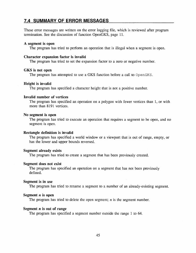
7.4 SUMMARY OF ERROR MESSAGES
These error messages are written on the error logging file, which is reviewed after program termination. See the discussion of function OpenGKS, page 11.
A segment is openThe program has tried to perform an operation that is illegal when a segment is open.
Character expansion factor is invalidThe program has tried to set the expansion factor to a zero or negative number.
GKS is not openThe program has attempted to use a GKS function before a call to OpenGKS.
Height is invalidThe program has specified a character height that is not a positive number.
Invalid number of verticesThe program has specified an operation on a polygon with fewer vertices than 1, or with more than 8191 vertices.
No segment is openThe program has tried to execute an operation that requires a segment to be open, and no segment is open.
Rectangle definition is invalidThe program has specified a world window or a viewport that is out of range, empty, or has the lower and upper bounds reversed.
Segment already existsThe program has tried to create a segment that has been previously created.
Segment does not existThe program has specified an operation on a segment that has not been previously defined.
Segment is in useThe program has tried to rename a segment to a number of an already-existing segment.
Segment n is openThe program has tried to delete the open segment; n is the segment number.
Segment n is out of rangeThe program has specified a segment number outside the range 1 to 64.
45

Transformation is invalidThe program has specified a normalization transformation outside the range allowed: for SetWindow and SetViewport, the range is 1 to 64; for other functions, the range is 0 to 64.
Transformation does not existThe program has specified an operation with a normalization transformation that has not been previously defined.
Up-vector has length = 0The program has specified a character up-vector with both components equal to zero.
Warning: High X exceeds display boundA viewport has been set with an x range that exceeds the physical limits of the graphic CRT mode chosen when GKS was opened. This is a warning, and not an error, to accommodate the greater X range of the SummaSketch graphics tablet (if used).
7.5 LISTING OF PROGRAM OILPLOT - ANSI TURBO C
This program plots a graph of oil production in three regions (north, central, and south) of an arbitrary country, for each year from 1980 to 1985. The production levels are read from the input file OILPLOT.DAT. The name of the country, the reference to the source of the data, and the coordinates of the contour of the country's map are read from user input. The program labels and scales the X- and Y-axes, puts a legend label on each graph, draws the graphs in different line styles, and marks the vertices of the graphs with different marker symbols. It writes a title and subtitle at the top of the plot, and plots a filled map of the country split into north, central, and south regions.
#include <stdio.h> ^include "\gks\gks.h"
/* _ _ _ _ __ prototypes
void Initialize ( float [], FILE ** );void DrawCurve ( FILE *, float [], int, int, char [] );void DrawFrame ();void ScaleAxes ()/void DrawTitle ();void Def ineMapWindow ( float *, float *, float *, float *void ReadMapCoord ( float [], float [], int * );void SetNorthWindow ( float, float, float, float ) ;void PlotMap ( int, int, float [], float [] );void SetCentralWindow ( float, float, float, float ) ;void SetSouthWindow ( float, float, float, float ) ;void CloseAll (FILE *) ;
I x . .-. . ___ -- . _. __ _ uici in
void main ()
{ int MapSize; /* number of vertices in the map */
46

float CurvX [6], MapX [201], MapY [201], XWLL, XWUR, YWLL, YWUR;
FILE *InFile;
/* array of x-coordinates for the 3 curves */ /* arrays for vertices of map */
/* Map window boundaries: LL = lower left corner */ /* UR = upper right corner */
/* input file for reading curve coordinates */
Initialize ( CurvX, &InFile );DrawCurve ( InFile, CurvX, Solid, Square, "SOUTH" );DrawCurve ( InFile, CurvX, Dotted, Triangle, "NORTH" );DrawCurve ( InFile, CurvX, Dashed, Circle, "CENTRAL" );DrawFrame ();ScaleAxes ();DrawTitle ();DefineMapWindow ( &XWLL, &YWLL, &XWUR, &YWUR );ReadMapCoord ( MapX, MapY, SMapSize );SetNorthWindow ( XWLL, YWLL, XWUR, YWUR );PlotMap ( MapSize, Slat, MapX, MapY );SetCentralWindow ( XWLL, YWLL, XWUR, YWUR );PlotMap ( MapSize, Grid, MapX, MapY );SetSouthWindow ( XWLL, YWLL, XWUR, YWUR );PlotMap ( MapSize, Solid, MapX, MapY );CloseAll (InFile);
/* Initialize - --This function does various initializations: it opens GKS, establishes normalization transformations for the main plotting area (#1) and the curve legends (#5), initializes the array of x-coordinates for the three curves, and opens the input file. Export: CurvX = the array of x-coordinates for the 3 curves;
InFile = the input data file (open) ____________ ________________________________________________________*/
void Initialize ( float CurvX [], FILE **InFile )
{ int Year;
OpenGKS ( "OILPLOT.ERR" );SetWindow ( 1, 1980, 1985, 0, 60000.0 ); /* NT = 1 for main graph */SetViewport ( 1, 0.1, 0.9, 0.1, 0.9 );SetWindow ( 5, 0, 12000, 0, 60000.0 ); /* NT = 5 for graph labels */SetViewport ( 5, 0.1, ( 0.1 + 0.8 / 5 ), 0.1, 0.9 );for ( Year = 0; Year < 6; ++Year )
CurvX [Year] = Year + 1980; /* X coordinates */ *InFile = fopen ( "\\gks\\OILPLOT.DAT", "r" );
/* DrawCurve ----------------------------------This function draws a given oil-production curve (polygon) by reading its y-coordinates from the input file, then plotting it in window #1 with a given line type and marking its vertices with a given marker symbol. The curve is labeled with a given legend, aligned parallel to the polygon in the region between years 1980 and 1981. Import: InFile = the input file (open)
CurvX = the array of x-coordinates of the production curve LineType = index of the line style for the curve MarkType = index of the marker style for the vertices Legend = string to be used in identifying the curve
47

void DrawCurve ( FILE *InFile, float CurvX [], int LineType, int MarkType, char Legend [] )
{ float CurvY [6]; int K;
for ( K = 0; K < 6; ++K ) /* read curve Y */fscanf ( InFile, "%f", &CurvY [K] );
SelectNormTrans (1) ; SetClipInd (NoClip); SetLineType (LineType); PolyLine ( 6, CurvX, CurvY ); SetMarkerType (MarkType); SetLineType (Solid); PolyMarker ( 6, CurvX, CurvY ); SelectNormTrans (5); SetTextFont (Stroke); SetCharHeight (1800); SetTextAlign ( Center, Bottom );SetCharUpVect ( CurvY [0] - CurvY [1], 12000 ); Text ( 6000, ( CurvY [0] + CurvY [1] ) / 2, Legend );
/* draw curve */
/* mark curve */ /* label curve */
/* -- - - DrawFrame - - - - - -- This function draws a rectangular frame around the plot area, using normalization transformation #1.
void DrawFrame ()
{ SelectNormTrans (1) ;Line ( 1980, 0, 1985, 0 );Line ( 1985, 0, 1985, 60000.0 );Line ( 1985, 60000.0, 1980, 60000.0 );Line ( 1980, 60000.0, 1980, 0 );
*/
/* ScaleAxes - This function plots scaling ticks, tick labels, and axis labels on the x- and y-axes.
void ScaleAxes ()
{ int Year, Tons;
char Legend [72];
SetWindow ( 2, 1980, 1985, 0, 5.0/8.0 );SetViewport ( 2, 0.1, 0.9, 0, 0.1 );SelectNormTrans (2) ;SetCharHeight (0.16);SetTextAlign ( Center, Top );SetCharUpVect ( 0, 1 );SetTextFont (Simplex);for ( Year = 1980; Year <= 1985; ++Year )
{ sprintf ( Legend, "%4d", Year ); Text ( Year, 0.5, Legend ); Line ( Year, 5.0/8.0, Year, 3.0/4.0 )
}SetWindow ( 3, 0, 60000.0/8.0, 0, 60000.0 ) SetViewport ( 3, 0, 0.1, 0.1, 0.9 );
/* scale X-axis */
/* X tick */
48

SelectNormTrans (3) / SetCharHeight (1600); SetTextAlign ( Right, Half );for ( Tons = 0; Tons <= 6; ++Tons ) /* scale Y-axis */
{ sprintf ( Legend, "%3d ", 10 * Tons );Text ( 60000.0 / 8.0, 10000.0 * Tons, Legend )/Line ( 60000.0 / 8.0, 10000.0 * Tons, /* Y tick */
70000.0 / 8.0, 10000.0 * Tons ); }
SetCharHeight (2600); SetTextAlign ( Left, Half ); SetTextPath (Down); Text ( 0, 30000.0, "BILLION BBL" ); /* label Y-axis */
/* DrawTitle ---------------------------------This function requests plot title and subtitle information from the operator, and plots these strings at the top of the picture area._______________________ __________________________________________________*
void DrawTitle ()
{ char InStr [60], /* variable for string input */Legend [73];
int Status, StrLen;
SelectNormTrans (0); /* read and plot title and subtitle */ SetCharUpVect ( 0, 1 ); SetTextPath (Right); SetCharHeight (0.03); SetTextAlign ( Center, Top );RequestString ( "Name of map: ", SStatus, SStrLen, InStr ); strcpy ( Legend, "OIL PRODUCTION IN " ); strcat ( Legend, InStr ); Text ( 0.5, 1, Legend ); SetTextFont (Standard); SetCharHeight (0.023); SetTextAlign ( Center, Bottom ) ;RequestString ( "Source of data: ", &Status, &StrLen, InStr ); strcpy ( Legend, "Source: " ); strcat ( Legend, InStr ) ; Text ( 0.5, 0.905, Legend );
}
/* _ _ _ __ _____ DefineMapWindow --- - - -- --- This function requests the operator to enter the dimensions of the world window that encloses the map being digitized. Export: XWLL, YWLL - x- and y-coordinates of the lower left corner of the
map world window; XWUR, YWUR = x- and y-coordinates of the upper right corner of the
map world window; _ __ _ _ ________________________________*/
void DefineMapWindow ( float *XWLL, float *YWLL, float *XWUR, float *YWUR )
{ float XVLL, YVLL, XVUR, YVUR;
int Status, NT;
49

SetWindow (9,0,1.5, 0, 1);SetViewport ( 9, 0, 1.5, 0, 1 );SetViewportPri ( 9, 0, Higher );RequestLoc ( "Locate lower left window corner ",
&Status, &NT, &XVLL, &YVLL ); RequestLoc { "Locate upper right window corner ",
&Status, &NT, &XVUR, &YVUR );SetViewport ( 10, XVLL, XVUR, YVLL, YVUR );RequestVal ( "World window X lower left = ", &Status, XWLL ); RequestVal ( "World window Y lower left = ", SStatus, YWLL ); RequestVal ( "World window X upper right = ", &Status, XWUR ); RequestVal ( "World window Y upper right = ", &Status, YWUR ); SetWindow ( 10, *XWLL, *XWUR, *YWLL, *YWUR ); SetViewportPri ( 10, 9, Higher );
/* - - ReadMapCoord - - _____ This function locates the coordinates of the map by requesting them to be entered manually from the graphics tablet.Export: MapX, MapY = arrays of x- and y-coordinates of the digitized map;
MapSize = number of vertices in the map polygons.
void ReadMapCoord ( float MapX [], float MapY [], int *MapSize )
{ int K,Status, StrLen, NT;
*/float X,
Y;
/* loop counter *//* for returned input status *//* for returned input string length *//* returned normalization transformation in locator input
/* X locator input *//* Y locator input */
*MapSize = -1;do /* input map coordinates from tablet */
{ RequestLoc ( "Locate map vertex ", SStatus, &NT, &X, &Y ); if ( Status == OK )
{ ++*MapSize;MapX [ *MapSize ] = X; MapY [ *MapSize ] = Y;
} } while ( Status == OK );
}i* ______________________________ SetNorthWindow -This function sets and selects the normalization transformation #6 forplotting the north third of the map.Import : XWLL, YWLL = x- and y-coordinates of the lower left corner of
the world window;XWUR, YWUR = x- and y-coordinates of the upper right corner of
the world window.
void SetNorthWindow ( float XWLL, float YWLL, float XWUR, float YWUR )
{ SetWindow ( 6, XWLL, XWUR, ( 2 * YWUR + YWLL ) / 3.0, YWUR ); SetViewport ( 6, 0.905, 1.2, 0.6, 0.7529 ); SelectNormTrans (6);
50
/* PlotMap This function plots the given map in the current viewport and fills it in a given fill style.Import: MapSize = number of vertices in the map polygon;
FillStyle = index of the polygon fill style;MapX, MapY = arrays of x- and y-coordinates of the map polygon.
______________________________________________________________________*/
void PlotMap { int MapSize, int FillStyle, float MapX [], float MapY [] )
{ SetClipInd (Clip);SetFillStyle (FillStyle) ;FillArea ( MapSize, MapX, MapY );
}
/* ___ Set Cent ralwindow - - ------This function sets and selects the normalization transformation #7 forplotting the central third of the map.Import : XWLL, YWLL = x- and y-coordinates of the lower left corner of
the world window; XWUR, YWUR = x- and y-coordinates of the upper right corner of
the world window. _ _ _ __________________________________*/
void SetCentralWindow ( float XWLL, float YWLL, float XWUR, float YWUR )
{ SetWindow ( 7, XWLL, XWUR, ( 2 * YWLL + YWUR ) / 3.0,( 2 * YWUR + YWLL ) / 3.0 );
SetViewport ( 7, 0.905, 1.2, 0.4235, 0.5765 );SelectNormTrans (7) ;
}
/* SetSouthWindow This function sets and selects normalization transformation #8 forplotting the south third of the map.Import : XWLL, YWLL = x- and y-coordinates of the lower left corner of
the world window; XWUR, YWUR = x- and y-coordinates of the upper right corner of
the world window.______________________________________________ * /_____________________________ *i
void SetSouthWindow ( float XWLL, float YWLL, float XWUR, float YWUR )
{ SetWindow ( 8, XWLL, XWUR, YWLL, ( 2 * YWLL + YWUR ) / 3.0 );SetViewport ( 8, 0.905, 1.2, 0.2471, 0.4 );SelectNormTrans (8) ;
}
/* CloseAll This function closes the input file, and it closes GKS.____ __ ___ __________________________________________________ ______*/
void CloseAll ( FILE *InFile )
{ fclose (InFile);CloseGKS ();
}
51