u.s. department of transportation safety/test procedures... · u.s. department of transportation...
TRANSCRIPT

TP-213-09 June 7, 2006
(Effective compliance date September 1, 2007)
U.S. DEPARTMENT OF TRANSPORTATION
NATIONAL HIGHWAY TRAFFIC SAFETY ADMINISTRATION
LABORATORY TEST PROCEDURE
FOR
FMVSS 213
Child Restraint Systems
ENFORCEMENT Office of Vehicle Safety Compliance
Room 6111, NVS-220 400 Seventh Street, SW Washington, DC 20590

ii
OVSC LABORATORY TEST PROCEDURE NO. 213 TABLE OF CONTENTS
PAGE 1. PURPOSE AND APPLICATION ............................................................................. 1 2. GENERAL REQUIREMENTS................................................................................. 2 3. SECURITY.............................................................................................................. 9 4. GOOD HOUSEKEEPING ....................................................................................... 9 5. TEST SCHEDULING AND MONITORING ............................................................. 9 6. TEST DATA DISPOSITION.................................................................................... 9 7. GOVERNMENT FURNISHED PROPERTY (GFP)................................................. 10 8. CALIBRATION OF TEST INSTRUMENTS ............................................................. 11 9. PHOTOGRAPHIC DOCUMENTATION .................................................................. 12 10. DEFINITIONS ......................................................................................................... 14 11. PRETEST REQUIREMENTS ................................................................................. 17 12. COMPLIANCE TEST EXECUTION ........................................................................ 19 13. POST TEST REQUIREMENTS .............................................................................. 81 14. REPORTS .............................................................................................................. 81 14.1. MONTHLY STATUS REPORTS................................................................... 81 14.2. APPARENT TEST FAILURE ........................................................................ 81 14.3. FINAL TEST REPORTS............................................................................... 81 14.3.1. COPIES ............................................................................................ 81 14.3.2. REQUIREMENTS ............................................................................. 82 14.3.3. FIRST THREE PAGES ..................................................................... 82 14.3.4. TABLE OF CONTENTS.................................................................... 87
14.3.5. PURPOSE AND TEST PROCEDURE ............................................. 88

iii
TABLE OF CONTENTS (Continued)
15. DATA SHEETS....................................................................................................... 89 Data Sheet 1 – Inspection and Test Data ............................................................... 90 Data Sheet 2 – Labeling ......................................................................................... 91 Data Sheet 3 – Installation Instructions................................................................... 102 Data Sheet 4 – Registration Form .......................................................................... 108 Data Sheet 5 – Attachment to Anchorage System.................................................. 112 Data Sheet 6 – Installation...................................................................................... 113 Data Sheet 7 – Minimum Head Support Surface .................................................... 114 Data Sheet 8 – Torso Impact Protection ................................................................. 115 Data Sheet 9 – Protrusion Limitation ...................................................................... 116 Data Sheet 10 – Dynamic Impact Test Conditions ................................................. 117 Data Sheet 11 – Belt Restraint ............................................................................... 119 Data Sheet 12 – Buckle Release ............................................................................ 120 Data Sheet 13 – Restraint System Integrity ............................................................ 121 Data Sheet 14 – Injury Criteria................................................................................ 122 Data Sheet 15 – Occupant Excursion..................................................................... 123 Data Sheet 16 – Occupant Excursion..................................................................... 124 Data Sheet 17 – Aircraft Passenger Seat Inversion Test........................................ 125 Data Sheet 18 - Aircraft Passenger Seat Inversion Test........................................ 126 Data Sheet 19 – Flammability Test......................................................................... 127 Data Sheet 20 – Webbing Performance Tests........................................................ 128 Data Sheet 21 – Belt Buckle and Adjustment Hardware Performance Tests.......... 130 16. FORMS................................................................................................................... 132 APPENDIX A RESERVED.............................................................................................................. A-i APPENDIX B PART 572(I) SIX-YEAR-OLD HII CHILD TEST DUMMY PERFORMANCE VERIFICATION TEST PROCEDURE …………………………… B-i APPENDIX C PART 572(N) SIX-YEAR-OLD HIII CHILD TEST DUMMY PERFORMANCE VERIFICATION TEST PROCEDURE......................................... C-i APPENDIX D PART 572(P) THREE-YEAR-OLD CHILD TEST DUMMY PERFORMANCE VERIFICATION TEST PROCEDURE......................................... D-i APPENDIX E PART 572(R) TWELVE-MONTH-OLD CHILD TEST DUMMY PERFORMANCE VERIFICATION TEST PROCEDURE......................................... E-i APPENDIX F BUILT-IN CHILD RESTRAINT REPORT TEMPLATE............................................. F-i APPENDIX G PART 572(S) SIX-YEAR-OLD WEIGHTED CHILD TEST DUMMY PERFORMANCE VERIFICATION TEST PROCEDURE…………………………….. G-i

iv
LIST OF FIGURES
1. TEST PROCEDURE ORGANIZATION................................................................... 4 2. MATERIALS TESTS FLOW CHART ...................................................................... 4 3. FLAMMABILITY TEST FLOW CHART ................................................................... 5 4. WEBBING PERFORMANCE TESTS FLOW CHART............................................. 5 5. BELT BUCKLE ADJUSTMENT HARDWARE PERFORMANCE TESTS ............... 6 6. DELETED .......................................................................................................... 6 7. INSPECTION OF PHYSICAL FEATURES FLOW CHART..................................... 7 8. DYNAMIC IMPACT TEST FLOW CHART .............................................................. 7 9. FAA INVERSION (ROLLOVER) PERFORMANCE TEST FLOW CHART.............. 8 10. ENCLOSURE CABINET, U-FRAME AND U-FRAME STAND................................ 23 11. BREAKING STRENGTH TEST DEVICE ................................................................ 27 12. ABRASION TEST SCHEMATIC ............................................................................. 27 13. BUCKLE ABRASION TEST SCHEMATIC.............................................................. 28 14. SEAT BACK WIDTH MEASUREMENT .................................................................. 39 15. SORL AND BELT ANCHORAGE POINT LOCATIONS ON THE STANDARD SEAT ASSEMBLY ............................................................................. 48 16. LOCATIONS OF BELT ANCHORAGE POINTS AND FORWARD EXCURSION LIMIT ON THE STANDARD SEAT ASSEMBLY............................... 48 15a. SORL AND LOCATION OF UNIVERSAL CHILD RESTRAINT ANCHORAGE
SYSTEM ON THE STANDARD SEAT ASSEMBLY ............................................... 49 16a. LOCATION OF UNIVERSAL CHILD RESTRAINT ANCHORAGE SYSTEM AND FORWARD EXCURSION LIMITS FOR THE STANDARD SEAT ASSEMBLY....... 49 17. CONFIGURATION I ACCELERATION FUNCTION CURVE .................................. 56 18. CONFIGURATION II ACCELERATION FUNCTION CURVE ................................. 56 19. WEBBING TENSION PULL DEVICE...................................................................... 67 20. PRE-IMPACT BUCKLE RELEASE FORCE TEST SETUP .................................... 70

v
LIST OF FIGURES (continued) 21. BUCKLE RELEASE TEST CONFIGURATION....................................................... 72 22. RELEASE FORCE APPLICATION DEVICE – PUSHBUTTON RELEASE BUCKLES.................................................................... 73 23. REAR FACING CHILD RESTRAINT FORWARD AND UPPER HEAD EXCURSION LIMITS.............................................................................................. 76 24. SIMULATED AIRCRAFT PASSENGER SEAT....................................................... 78 25. INTERFACE PROFILE OF TETHER HOOK .......................................................... 79
LIST OF TABLES
1. TEST CONFIGURATION I ACCELERATION FUNCTION ENVELOPE ................. 54 2. TEST CONFIGURATION II ACCELERATION FUNCTION ENVELOPE ................ 55 3. DUMMY SELECTION BY MASS AND HEIGHT ..................................................... 57

REVISION CONTROL LOG FOR OVSC LABORATORY
TEST PROCEDURES
TP-213 Child Restraint Systems
TEST PROCEDURE FMVSS 213
REV. No.
DATE
AMENDMENT
EFFECTIVE DATE
DESCRIPTION
00 Original Issue
01 Minor Revisions
02 Revised for additional requirements
03 April 12, 1994
Conversion to WordPerfect and minor corrections
04 Sept. 1, 1997
59 FR 37167 60 FR 35126
Aug. 22, 1994 Jan. 3, 1996
General update. Addition of booster seats and expanded number of test dummies.
05 Dec. 18, 2003
64 FR 47566 67 FR 61523
Sep. 1, 2002 Oct. 1, 2003
Addition of LATCH requirements. Addition of revised label requirements.
06 June 30, 2004
68 FR 37620 Voluntary Compliance
Dec. 22, 2003 Fully Effective Aug. 1, 2005
Additional requirements to upgrade S213 per TREAD Act mandate.
07 June 1, 2005
69 FR 42595 70 FR 15596
August 1, 2005
Addition of Hybrid III six-year-old weighted dummy. Minor revision based on Denton ATD petition for reconsideration.
08 November 1, 2005
70 FR 35556 70 FR 44520 70 FR 53569
June 21, 2006 Aug. 1, 2005 Nov. 8, 2005
Revised Hotline number and addition of web address. Optional use of 6 yr. old HII dummy. Addition of online registration requirements.
09 June 7, 2006
71 FR 32855 August 7, 2006
(effective date) September 1,
2007 (compliance date)
Revised to incorporate minimum breaking strength requirements for webbing.
10
vi

1
1. PURPOSE AND APPLICATION
The Office of Vehicle Safety Compliance (OVSC) provides contractor laboratories with Laboratory Test Procedures as guidelines for obtaining compliance test data. The data are used to determine if a specific vehicle or item of motor vehicle equipment meets the minimum performance requirements of the subject Federal Motor Vehicle Safety Standard (FMVSS). The purpose of these OVSC Laboratory Test Procedures is to present a uniform testing and data recording format, and provide suggestions for the use of specific equipment and procedures. These Laboratory Test Procedures do not constitute an endorsement or recommendation for use of a any product or method. If any contractor views any part of the OVSC Laboratory Test Procedures (TP) to be in conflict with a FMVSS or observes deficiencies in a TP, the contractor is required to advise the Contracting Officer's Technical Representative (COTR) and resolve the discrepancy prior to the start of compliance testing. Every contractor is required to submit a detailed test procedure to the COTR before initiating the compliance test program. The procedure must include a step-by-step description of the methodology to be used. The contractor's test procedure shall contain a complete listing of test equipment with make and model number and a detailed check-off sheet. The list of test equipment shall include instrument accuracy and calibration dates. All equipment shall be calibrated in accordance with the manufacturer’s instructions. There shall be no contradictions between the TP and the contractor’s in-house test procedure. Written approval of the in-house test procedures shall be obtained from the COTR before initiating the compliance test program. The TP is not intended to limit or restrain a contractor from developing or utilizing any testing techniques or equipment that will assist in procuring the required compliance test data. However, the application of any such testing technique or equipment is subject to prior approval of the COTR.
NOTE: This TP, prepared for the limited purpose of use by contracted independent laboratories conducting compliance tests for the OVSC, are not rules, regulations, or NHTSA interpretations regarding the meaning of a FMVSS. Neither is the TP intended to limit the requirements of the applicable FMVSS(s). In some cases, the TP does not include all of the various FMVSS minimum performance requirements. Recognizing applicable test tolerances, the TP may specify test conditions that are less severe than the minimum requirements of the standard. In addition, the TP may be modified by the OVSC at any time without notice, and the COTR may direct or authorize contractors to deviate from these procedures, as long as the tests are performed in a manner consistent with the standard itself and within the scope of the contract. Laboratory Test Procedures may not be relied upon to create any right or benefit in any person. Therefore, compliance of a vehicle or item of motor vehicle equipment is not necessarily guaranteed if the manufacturer limits its certification tests to those described in the TP.
2
2. GENERAL REQUIREMENTS
The test procedures, methods, and associated equipment are based on the requirements of the following documents to the extent referenced herein.
49 CODE OF FEDERAL REGULATIONS (CFR) 571 FEDERAL MOTOR VEHICLE SAFETY STANDARDS (FMVSS)
FMVSS 213 - Child Restraint Systems FMVSS 209 - Seat Belt Assemblies FMVSS 302 - Flammability of Interior Materials
FMVSS 225 - Child Restraint Anchorage Systems
49 CODE OF FEDERAL REGULATIONS (CFR) 572 ANTHROPOMORPHIC TEST DEVICES
Subpart K - Newborn Infant Subpart R – Twelve-Month-Old Infant Subpart P - Three-Year-Old Child Subpart N - Six-Year-Old Child Subpart S – Six-Year-Old Weighted Child
STANDARD BENCH SEAT -- Drawing Package SAS-100-1000 with Addendum A, dated October 23, 1998, or in Drawing Package NHTSA-213-2003 dated June 3, 2003.
AMERICAN ASSOCIATION OF TEXTILE CHEMISTS AND COLORISTS (AATCC)
AATCC Geometric Gray Scale AATCC Test Method 30-81 Fungicides Evaluation of Textiles; Mildew and Rot
Resistance of Textiles
AMERICAN SOCIETY FOR TESTING AND MATERIALS (ASTM) ASTM B117-73 Standard Method for Salt Spray (Fog) Testing ASTM D756-78 Standard Practice for Determination of Weight and Shape
Changes of Plastics Under Accelerated Service Conditions ASTM D1056-73 Standard Specification for Flexible Cellular Materials--Sponge or
Expanded Rubber ASTM D3574-05 Standard Methods of Testing Flexible Cellular Materials--Slab
Urethane Foam

3
2. GENERAL REQUIREMENTS....Continued ASTM D1565-76 Standard Specifications for Flexible Cellular Materials--Vinyl
Chloride Polymers and Copolymers (Open-Cell Foam) ASTM E4-79 Standard Methods of Load Verification of Testing Machines ASTM G23-81 Standard Practice for Operating Light Exposure Apparatus
(Carbon Arc Type) with and without Water for Exposure of Nonmetallic Materials
SOCIETY OF AUTOMOTIVE ENGINEERS (SAE) SAE J211 Instrumentation for Impact Tests AMERICAN NATIONAL STANDARDS INSTITUTE
ANSI/NCSL Z540-1 Calibration Laboratories and Measuring and Test Equipment – General Requirements
MILITARY STANDARD MIL-SPEC 43006 Nylon Impregnated Vinyl
ENVIRONMENTAL CONDITIONS Unless otherwise specified, all tests and measurements shall be conducted under the following environmental conditions:
Temperature 19°C (66°F) to 26°C (78°F) Relative Humidity 10% to 70%
All data on environmental conditions required throughout this procedure shall be continuously and permanently recorded on strip charts, circular charts, or other acceptable printout media.
TEST SEQUENCE
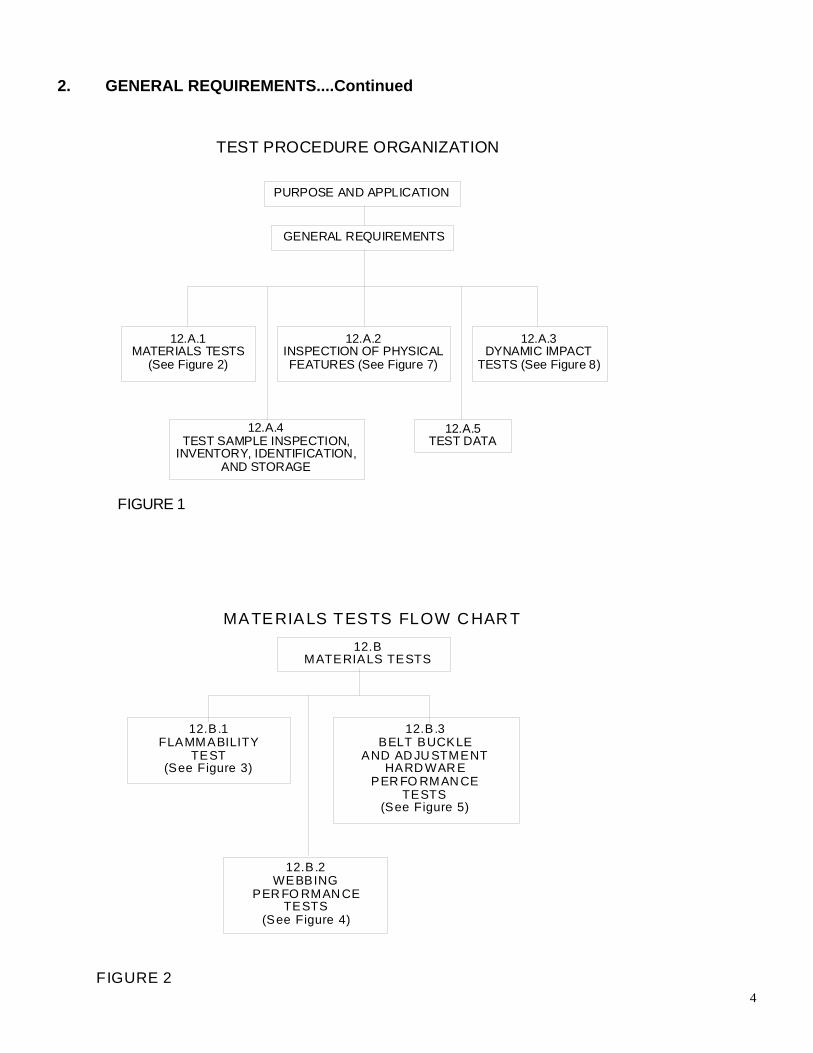
The overall organization of this test procedure is shown in Figure 1 on the next page. The following three test series may be done simultaneously or sequentially in any order.
MATERIALS TESTS (shown in Figures 2 through 6) INSPECTION OF PHYSICAL FEATURES (shown in Figure 7) DYNAMIC IMPACT TEST (shown in Figure 8)
Additional tests are required for child restraint systems manufactured for use in aircraft in addition to motor vehicle.
TESTING FOR AIRCRAFT USE (shown in Figure 9)
2. GENERAL REQUIREMENTS....Continued
GENERAL REQUIREMENTS
12.A.2INSPECTION OF PHYSICALFEATURES (See Figure 7)
12.A.3DYNAMIC IMPACT
TESTS (See Figure 8)
TEST PROCEDURE ORGANIZATION
PURPOSE AND APPLICATION
12.A.1MATERIALS TESTS
(See Figure 2)
12.A.5TEST DATA
12.A.4TEST SAMPLE INSPECTION,
INVENTORY, IDENTIFICATION,AND STORAGE
FIGURE 1
4
12.B.1FLAMMABILITY
TEST(See Figure 3)
12.B.2WEBBING
PER FO RMAN CETESTS
(See Figure 4)
12.B.3BELT BUCKLE
AND AD JU STMENTHARD WAR E
PER FO RMAN CETESTS
(See Figure 5)
MATERIALS TESTS FLOW C HAR T12.B
MATERIALS TESTS
FIGURE 2

2. GENERAL REQUIREMENTS....Continued
FLAMMABILITY TEST FLOW CHART
12.B.1 --- FLAMMABILITY TEST
12.B.1.4 --- SPECIMEN PREPARATION
12.B.1.2 --- ENVIRONMENTAL CONDITIONS
12.B.1.5 --- TEST PROCEDURE
12.B.1.6 --- PERFORMANCE REQUIREMENTS
FIGURE 3
12 .B.2 --- WE BB ING P ER F O R M AN C E T E ST S
W EBB IN G PERF ORM AN CE TES TS FLOW CHART
1 2. B .2 .2B R EA K IN G
S TR E N GT H(Pro vid es b a se -
line bre a kingst re n g th o f
n on -d eg ra de db elt w e b bin g .)
1 2. B .2 .7W I D TH
M E AS U R E M E N T
1 2. B .2 .2B R EA K IN G S TR E N G TH
(D e gra d ed b e ltw e bb in g sp e cim en s)
1 2. B .2 .3R E SI ST AN C E
TO A B R AS IO N
C O N D IT I ON IN G P ER1 2. B .2 .4
E N VI R ON M EN T ALR E QU I R E M EN T S
1 2. B .2 .4R E SI ST AN C ETO B U C K LEA BR A S IO N
1 2. B .2 .5R E SI ST AN C E
TO L IG H T
1 2. B .2 .6R E SI ST AN C E
TO M I C R O-O R GA N IS M S
C O N D IT I ON P ER1 2. B .2 .1
E N VI R ON M EN T ALR E QU I R E M EN T S
C O N D IT I ON P ER 12 . B. 2. 1E N VI R ON M EN T AL R E Q U IR E M E N TS
C O N D IT I ON S PE R1 2. B .2 .1
E N VI R ON M EN T ALR E QU I R E M EN T S
F IGURE 4
5

2. GENERAL REQUIREMENTS....Continued
12.B.3BELT BUCKLE AND ADJUSTMENT
HARDWARE PERFORMANCE TESTS
12.B.3.3BUCKLE
RELEASEACCESS
12.B.3.4ADJUST-
MENTFORCE
12.B.3.5TILT-LOCK
ADJUST-MENT
12.B.3.6BUCKLELATCH /
PARTIALENGAGEMENT
BELT BUCKLE ADJUSTMENT HARDWAREPERFORM ANCE TESTS
12.B.3.1CORROSION RESISTANCE
(All Hardware)
12.B.3.2TEMPERATURE RESISTANCE
(Plastic and Nonmetallic Hardware)
FIGURE 5
RESERVED FIGURE 6
6

2. GENERAL REQUIREMENTS....Continued
12.C --- INSPECTION OF PHYSICAL FEATURES
INSPECTION OF PHYSICAL FEATURES FLOW CHART
12.C.1LABELING
12.C.5BELT
RESTRAINT
12.C.6TORSOIMPACT
PROTECTION
12.C.4MINIMUM
HEAD SUPPORTSURFACE
12.C.1LABELING
12.C.7HEAD
IMPACTPROTECTION
12.C.8PROTRUSIONLIMITATION
12.C.3INSTALLATION
12.C.2INSTALLATIONINSTRUCTIONS
FIGURE 7
DYNAMIC IMPACT TEST FLOW CHART
12.DDYNAMIC
IMPACT TEST
12.D.1TEST EQUIPMENT
12.D.2SYSTEMS CHECK
12.D.3TEST CONDITIONS
12.D.4 --- DUMMY PREPARATION
12.D.5 --- RESTRAINT SETUP
12.D.6 --- IMPACT TEST
12.D.7 --- PERFORMANCE REQUIREMENTS
FIGURE 8
7

2. GENERAL REQUIREMENTS....Continued
12.E --- TESTING FOR AIRCRAFT USE
12.E.1 --- INSTALLATION INSTRUCTIONS
12.E.2 --- FAA INVERSION (ROLLOVER) TEST
FAA INVERSION (ROLLOVER)PERFORMANCE TEST FLOW CHART
FIGURE 9
Any interpretations and/or deviations from this Test Procedure shall be shown in Appendix A of the Final Test Report.
8

9
3. SECURITY
The contractor shall provide appropriate security measures to protect the OVSC test equipment from unauthorized personnel during the entire compliance-testing program. The contractor is financially responsible for any acts of theft and/or vandalism, which occur during the storage of test equipment. Any security problems, which arise, shall be reported by telephone to the Industrial Property Manager (IPM), Office of Contracts and Procurement, within two working days after the incident. A letter containing specific details of the security problem will be sent to the IPM (with copy to the COTR) within 48 hours. The contractor shall protect and segregate the data that evolves from compliance testing before and after each test. No information concerning the safety compliance-testing program shall be released to anyone except the COTR, unless specifically authorized by the COTR or the COTR's Supervisor.
NOTE: NO INDIVIDUALS, OTHER THAN CONTRACTOR PERSONNEL DIRECTLY INVOLVED IN THE COMPLIANCE TESTING PROGRAM, SHALL BE ALLOWED TO WITNESS ANY EQUIPMENT COMPLIANCE TEST UNLESS SPECIFICALLY AUTHORIZED BY THE COTR.
4. GOOD HOUSEKEEPING
Contractors shall maintain the entire equipment compliance testing area, test fixtures and instrumentation in a neat, clean and painted condition with test instruments arranged in an orderly manner consistent with good test laboratory housekeeping practices.
5. TEST SCHEDULING AND MONITORING
The contractor shall submit a test schedule to the COTR prior to testing. Tests shall be completed as required in the contract. All testing shall be coordinated to allow monitoring by the COTR.
6. TEST DATA DISPOSITION
The contractor shall make all equipment preliminary compliance test data available to the COTR on location within four hours after the test. Final test data, including digital printouts and computer generated plots (if applicable), shall be furnished to the COTR within five working days. Additionally, the contractor shall analyze the preliminary test results as directed by the COTR.
All backup data sheets, strip charts, recordings, plots, technicians’ notes, etc., shall be either sent to the COTR or retained by the contractor for a minimum of five years.

10
7. GOVERNMENT FURNISHED PROPERTY (GFP) ACCEPTANCE OF TEST EQUIPMENT
All equipment items will be inventoried upon receipt and checked against the shipping documents. Any missing or broken parts will be reported immediately to the COTR. A running inventory list will be maintained until the complete matrix list of test samples is received.
The three-year-old dummy (Part 572P), six-year-old dummy (Part 572N), twelve-month-old dummy (Part 572R), newborn infant dummy (Part 572K), and six-year-old weighted dummy (Part 572S) will be provided to the laboratory by OVSC. The twelve-month-old, three-year-old, and six-year-old dummies shall be calibrated by the laboratory before the start of the test program, after an apparent noncompliance with the Dynamic Impact Test requirements (unless waived by the COTR), after 30 tests, or if the dummy has been in storage for thirty days or more during a testing program. The dummy shall not be used for more than one test per hour. The twelve-month-old, three-year-old, six-year-old, and six-year-old weighted dummy calibration procedures are attached to this test procedure as Appendix E, D, C, and G, respectively. The newborn size dummy shall be visually inspected at the start of the test program and after an apparent noncompliance with the dynamic Impact Test requirements to check for cracks, tears or other physical damage and either repaired or replaced at the discretion of the COTR.

11
8. CALIBRATION OF TEST INSTRUMENTS
Before the contractor initiates the safety compliance test program, a test instrumentation calibration system shall be implemented and maintained in accordance with established calibration practices. The calibration system shall include the following as a minimum: A. Standards for calibrating the measuring and test equipment will be stored and used
under appropriate environmental conditions to assure their accuracy and stability. B. All measuring instruments and standards shall be calibrated by the contractor, or a
commercial facility, against a higher order standard at periodic intervals NOT TO EXCEED TWELVE (12) MONTHS! Records, showing the calibration traceability to the National Institute of Standards and Technology (NIST), shall be maintained for all measuring and test equipment.
C. All measuring and test equipment and measuring standards will be labeled with the
following information:
(1) Date of calibration (2) Date of next scheduled calibration (3) Name of the technician who calibrated the equipment
D. A written calibration procedure shall be provided by the contractor which includes as a
minimum the following information for all measurement and test equipment:
(1) Type of equipment, manufacturer, model number, etc. (2) Measurement range (3) Accuracy (4) Calibration interval (5) Type of standard used to calibrate the equipment (calibration traceability of the
standard must be evident) E. Records of calibration for all test instrumentation shall be kept by the contractor in a
manner that assures the maintenance of established calibration schedules. All such records shall be readily available for inspection when requested by the COTR. The calibration system need the acceptance by the COTR before the test program commences.
Further guidance is proved in the International Standard ISO 10012-1, “Quality Assurance Requirements for Measuring Equipment” and American National Standard ANSI/NCSL Z540-1, “Calibration Laboratories and Measuring and Test Equipment – General Requirements.”

12
9. PHOTOGRAPHIC DOCUMENTATION DYNAMIC TEST
Each final test report shall include glossy color photographs of the test item as received. The following format shall be used for these photographs: 35 mm pre and post test photographs taken at 90° and 45° angles of the restraint as installed on the standard bench, vehicle shell or vehicle. The restraint shall be photographed with no dummy in the seat for the configuration photo and each label on the restraint shall also be photographed.
FILM/VIDEO DOCUMENTATION
At the very beginning, and for each separate segment, film/video identification placards or slates covering the following description of the film/video:
A. Project title B. Test number where appropriate C. Date filmed/videoed D. Type of test or product being filmed/videoed E. Conditions of test or product being filmed/videoed FILM/VIDEO PRESERVATION AND IDENTIFICATION A. The film/video actually shot in the camera (the original) should never be edited. After
the original is developed, add an identifying leader to the beginning of the film/video (the head) with the following information on it:
(1) Project title (2) Inclusive test numbers where appropriate (3) The name of the filming/videoing organization (4) Date (5) The word "ORIGINAL" B. Make high quality duplicate of the original film/video (for film, a B-wind optical
duplicate master, liquid gate) as a protection copy, in case the original is lost or damaged. Make a work-print from the original to be used for editing. Affix identifying leaders to the heads of both the B-wind master and work-print as described in 8.2.2 (1) above.

13
9. PHOTOGRAPHIC DOCUMENTATION....Continued C. Store the video and copy or the original film and B-wind master on cores, heads out,
in plastic bags, and the bags in dust-proof cans or containers. Label storage containers with the same information as on the leaders, plus a notation of the length (time and feet), color or black and white, and silent or sound (magnetic or optical). Store containers in climate controlled vaults.
FILM/VIDEO EDITING
Edit the work-print to remove extraneous material. FILMS/VIDEOS FOR CIRCULATION
Reproduce prints for distribution (release prints) from the original film/video based on the final edited work-print.
FILM/VIDEO ABSTRACT
Prepare an abstract or description of the film’s/video's content to accompany the film/video when it is delivered to NHTSA.
DISPOSITION OF FILMS/VIDEOS A. For the purpose of duplicating prints for NHTSA and outside sources, the contractor
shall retain the original and video copy or B-wind master until NHTSA requests that they be delivered to NHTSA.
B. In addition to the number of prints required by the contracting Officer's Technical
Representative, the contractor shall provide one (1) print to the NHTSA Office of Vehicle Safety Compliance (OVSC), along with a copy of the abstract or description.
COMPONENT TEST
Each final test report shall include color photographs of the test item as received. Include a label with the name and model of test item, and the test numbers where appropriate. Include color photographs of testing equipment.

14
10. DEFINITIONS
ADD-ON CHILD RESTRAINT SYSTEM
Any portable child restraint system. BACKLESS CHILD RESTRAINT SYSTEM
A child restraint other than a belt-positioning seat, that consists of a seating platform that does not extend up to provide a cushion for the child’s back or head and has a structural element designed to restrain forward motion of the child’s torso in a forward impact.
BELT-POSITIONING SEAT
A child restraint system that positions a child on a vehicle seat to improve the fit of a vehicle Type II belt system on the child and that lacks any component, such as a belt system or a structural element, designed to restrain forward movement of the child’s torso in a forward impact.
BOOSTER SEAT
A child restraint that is either a backless child restraint system or a belt-positioning seat.
BUILT-IN CHILD RESTRAINT SYSTEM
Any child restraint system that is designed to be an integral part of and permanently installed in a motor vehicle.
CAR BED
A child restraint system designed to restrain or position a child in the supine or prone position on a continuous flat surface.
CHILD RESTRAINT ANCHORAGE SYSTEM
A vehicle system that is designed for attaching a child restraint system to a vehicle at a particular designated seating position, consisting of: (a) Two lower anchorages meeting the requirements of S9, FMVSS No. 225; and (b) A tether anchorage meeting the requirements of S6, FMVSS No. 225.
CHILD RESTRAINT SYSTEM
Any device, except Type I or Type II seat belts, designed for use in a motor vehicle or aircraft to restrain, seat, or position children who weigh 30 kg (66 pounds) or less.

15
10. DEFINITIONS....Continued
CONTACTABLE SURFACE
Any child restraint system surface (other than that of a belt, belt buckle, or belt adjustment hardware) that may contact any part of the head or torso of the appropriate test dummy, specified in S7, when a child restraint system is tested in accordance with S6.1 of FMVSS 213.
FACTORY INSTALLED BUILT-IN CHILD RESTRAINT
A built-in child restraint system that has been or will be permanently installed in a motor vehicle before that vehicle is certified as a completed or altered vehicle in accordance with part 567 of 49 CFR Chapter 5, certification requirements for passenger vehicles.
HARNESS A combination pelvic and upper torso child restraint system that consists primarily of flexible
material, such as straps, webbing or similar material, and that does not include a rigid seating structure for the child.
REAR-FACING CHILD RESTRAINT
A child restraint system, except a car bed, that positions a child to face in the direction opposite to the normal direction of travel of the motor vehicle.
REPRESENTATIVE AIRCRAFT PASSENGER SEAT
Either a Federal Aviation Administration approved production aircraft passenger seat or a simulated aircraft passenger seat conforming to Figure 24 of this OVSC Laboratory Test Procedure.
SEAT ORIENTATION REFERENCE LINE (SORL)
The horizontal line through Point Z as illustrated in Figure 15 and Figure 15a of this OVSC Laboratory Test Procedure.
SPECIFIC VEHICLE SHELL
The actual vehicle model part into which the built-in child restraint system is or is intended to be fabricated, including the complete surroundings of the built-in system. If the built-in child restraint system is or is intended to be fabricated as part of any seat other than a front seat, these surroundings include the back of the seat in front, the interior rear side door panels and trim, the floor pan, adjacent pillars (e.g., the B and C pillars), and the ceiling. If the built-in system is or is intended to be fabricated as part of the front seat, these surroundings include the dashboard, the steering mechanism and its associated trim hardware, any levers and knobs installed on the floor or on a console, the interior front side door panels and trim, the front seat, the floor pan, the A pillars and the ceiling.

16
10. DEFINITIONS....Continued
TETHER ANCHORAGE A user-ready, permanently installed vehicle system that transfers loads from a tether strap through the tether hook to the vehicle structure and that accepts a tether hook.
TETHER STRAP A strap that is secured to the rigid structure of the seat back of a child restraint system, and is connected to a tether hook that transfers the load from that system to the tether anchorage. TETHER HOOK A device, illustrated in Figure 11 of Standard No. 213 (§ 571.213), used to attach a tether strap to a tether anchorage.
TORSO
The portion of the body of a seated anthropomorphic test dummy, excluding the thighs, that lies between the top of the child restraint system seating surface and the top of the shoulders of the test dummy.

17
11. PRETEST REQUIREMENTS OPERATING TEST PROCEDURE
Prior to conducting any compliance test, contractors are required to submit a detailed in-house compliance test procedure to the COTR, which includes a step-by-step description of the methodology to be used. Written approval must be obtained from the COTR before initiating the compliance test program so that all parties are in agreement.
TEST DATA LOSS
A compliance test is not to be conducted unless all of the various test conditions specified in the applicable OVSC Laboratory Test Procedure have been met. Failure of a contractor to obtain the required test data and to maintain acceptable limits on test parameters in the manner outlined in the applicable OVSC Laboratory Test Procedure may require a retest at the expense of the contractor. The retest costs will include the cost of the replacement item of motor vehicle equipment and all costs associated with conducting the retest. The original test specimen used for the invalid test shall remain the property of OVSC, and the retest specimen shall remain the property of the contractor. If there is a test failure, the contractor shall retain the retest specimen for a period not exceeding two years. If there is no test failure, the Contractor may dispose of the test specimen upon notification from the COTR that the final test report has been accepted.
The Contracting Officer of NHTSA is the only NHTSA official authorized to notify the contractor that a retest is required. The retest shall be completed within two (2) weeks after receipt of notification by the Contracting Officer that a retest is required. If a retest is conducted, no test report is required for the original test.
GENERAL TEST CONDITIONS
Unless otherwise specified, all tests and measurements shall be conducted under the following environmental conditions:
Temperature 19°C (66°F) to 26°C (78°F) Relative Humidity 10% to 70%
The laboratory shall be capable of setting, controlling, and reading the environmental condition parameters so that when the accuracies of the instrumentation and the systems are considered in evaluating the recorded data, the results are within the upper and lower limits of the specifications.
Continuous recording of environmental conditions shall be provided for during all phases of testing. The environmental conditions shall be continuously recorded, as a minimum, using a strip chart recorder.

18
11. PRETEST REQUIREMENTS....Continued TEST PERSONNEL PERFORMANCE
Technicians charged with the responsibility of performing the compliance test program shall be thoroughly familiar with the requirements and test conditions for each test phase to be performed. Each technician shall be specifically instructed in the proper operation of all equipment employed in conducting these tests.
Personnel supervising the compliance test program shall be thoroughly familiar with the requirements, test conditions, and equipment for the test to be conducted.

19
12. COMPLIANCE TEST EXECUTION A. TEST SAMPLES A.1 MATERIALS TESTS Samples of all materials used in a given child restraint system shall be supplied by
NHTSA in appropriate quantities for the materials tests in this procedure and outlined in Figure 2.
(1) FLAMMABILITY TESTS One (1) sample of each direction as applicable (longitudinal and lateral), 102
mm (4 inches) wide by 356 mm (14 inches) long, or the maximum available width or length if less, of each nonmetallic material is required for the flammability tests outlined in Figure 3. The laboratory may be required to cut specimens from an actual child restraint system.
(2) WEBBING PERFORMANCE TESTS Twenty-four (24) samples, each 1,067 mm (42 inches) long, of each type of
webbing used on the child restraint system are required for the webbing performance tests outlined in Figure 4.
(3) BELT BUCKLE AND ADJUSTMENT HARDWARE PERFORMANCE TESTS Three (3) sets of all buckle and adjustment hardware and an additional three
sets of any plastic or nonmetallic buckle and adjustment hardware are required for the hardware performance tests outlined in Figure 5.
A.2 INSPECTION OF PHYSICAL FEATURES One child restraint system shall be supplied by NHTSA for the inspection of physical
features outlined in Figure 7.

20
12. COMPLIANCE TEST EXECUTION....Continued A.3 DYNAMIC IMPACT TESTS Child restraint systems shall be supplied by NHTSA for the dynamic impact tests
outlined in Figure 8. (1) DYNAMIC IMPACT TEST CONFIGURATION I One (1) child restraint system is required for EACH TEST according to
Dynamic Impact Test Configuration I. One or more tests are possible depending on the number of installation modes (forward facing/infant mode), adjustment positions (upright/recline), and height and weight recommendations of the manufacturer.
(2) DYNAMIC IMPACT TEST CONFIGURATION II One (1) child restraint system is required for EACH TEST according to
Dynamic Impact Test Configuration II. One or more tests are possible for each forward-facing system, other than a child harness, that is equipped with an anchorage belt or a fixed or movable surface directly forward of the dummy, in EACH ADJUSTMENT POSITION (i.e. upright or reclined) recommended by the manufacturer for actual use. Child restraint systems having both of the above features shall be tested with each feature “misused”, i.e., with the tether or restraint belts not attached, both separately and simultaneously. For each child restraint model, one or more tests are possible depending on the number of installation modes (forward facing/infant mode), adjustment positions (upright/recline), and height and weight recommendations of the manufacturer.
(3) RETEST One (1) child restraint system shall be available as a spare unit in the event
that a retest is required. A.4 FAA INVERSION TEST
One (1) child restraint is required for each FAA test performed. For each child restraint model, one or more tests are possible depending on the number of installation modes (forward/reverse), adjustment positions (upright/recline), and height and weight recommendations of the manufacturer.

21
12. COMPLIANCE TEST EXECUTION....Continued A.5 TEST SAMPLE INSPECTION, INVENTORY, IDENTIFICATION AND STORAGE All child restraint systems and associated extra materials and parts shall be stored
upon receipt in a clean, dry, secure storage area to prevent any damage or deterioration that might affect test results. Within one week of receipt, all samples shall be inspected, and the date of receipt and condition of the samples shall be recorded. Each sample shall also be marked or labeled with a systematic item-coding scheme to indicate the following:
1. Sequential number for entire sample set 2. Child restraint manufacturer and model 3. Sequential sample number within set 4. Type of test to be conducted with sample EXAMPLE: 001-XYZ-03-MW This item code shall be recorded on all Data Sheets applicable to the test sample. A.6 TEST DATA Test data shall be recorded in standard engineering units, when applicable, on Data
Sheets specifically prepared for this purpose, as shown in section 15 of this procedure.
For each FMVSS requirement indicated on the Data Sheets, determine compliance,
and record PASS, FAIL, NA (not applicable), or SEE REMARKS in the space provided. Any noncompliance should be explained under REMARKS.
The full set of Data Sheets shall be included in the Final Test Report. B. MATERIALS TESTS B.1 FLAMMABILITY TEST (S213, S5.7; S302, S4.1, S4.2)) B.1.1 GENERAL All nonmetallic materials of a child restraint system shall meet the flammability
requirements of S302 as outlined in this procedure. Any material that does not adhere to other material(s) at every point of contact shall meet the given requirements when tested separately. Any material that adheres to other

22
12. COMPLIANCE TEST EXECUTION....Continued material(s) at every point of contact shall meet these same requirements when tested
as a composite with the other materials. Indicate on the appropriate Data Sheets the type of material being tested and the specimen's function on the restraint system (i.e., padding, buckle, shell, etc.).
B.1.2 ENVIRONMENTAL CONDITIONS (S302, S5.1.2) Flammability tests shall be conducted under the following environmental conditions: Temperature 16°C (60°F) to 27°C (80°F) Relative Humidity 40% to 60% Each specimen shall be conditioned for a minimum of 24 hours under these
environmental conditions before subjecting it to the flammability test. B.1.3 EQUIPMENT REQUIREMENTS (S302, S5.1.1) Conduct the test in a metal cabinet for protecting the test specimens from drafts, as
shown in Figure 10 below. The interior of the cabinet is 381 mm (15 inches) long, 203 mm (8 inches) deep, and 356 mm (14 inches) high. It has a glass observation window in the front, a closable opening to permit insertion of the specimen holder, and a hole to accommodate tubing for a gas burner. For ventilation, it has a 13 mm (0.50 inch) clearance space around the top of the cabinet, ten (10) 19 mm (0.75 inch) diameter holes in the base of the cabinet, and legs to elevate the bottom of the cabinet by 10 mm (0.375 inch), all located as shown in the figure. If tested in exhaust hood, the maximum allowable airflow is 55CFM as measured at intake with sash opening of 127 mm (5 inches).
SPECIMEN SUPPORT FRAME (S302, S5.1.3) Insert the test specimen between two matching U-shaped frames of metal stock 25
mm (1 inch) wide and 10 mm (0.375 inch) high. The interior dimensions of the U-shaped frames are 51 mm (2 inches) wide by 330 mm (13 inches) long. A specimen that softens and bends at the flaming end so as to cause erratic burning is kept horizontal by supports consisting of thin, heat resistant wires, spanning the width of the U-shaped frame under the specimen at 25 mm (1 inch) intervals. A device that may be used for supporting this type of material is an additional U-shaped frame, wider than the U-shaped frame containing the specimen, spanned by 10 mil wires of heat-resistant composition at 25 mm (1 inch) intervals, inserted over the bottom U-shaped frame.

12. COMPLIANCE TEST EXECUTION....Continued FLAME SOURCE (S302, S5.1.4 and S5.1.5)
Use a Bunsen burner with a tube of 10 mm (0.375 inch) inside diameter. Set the gas-adjusting valve to provide a flame, with the tube vertical, of 38 mm (1.50 inches) ± 2 mm (0.0625 inch) in height. Close the air inlet to the burner. The gas supplied to the burner should have a flame temperature equivalent to that of natural gas.
TOP VIEW
FRONT VIEW
BOTTOM VIEW
RIGHTSIDEVIEW
203 mm(8")
381 mm (15")
356 mm(14")
127 mm(5")
38 mm (1-1/2")
38 mm (1-1/2")10 mm (3/8") LEG
HEAT RESISTANTON FRONT
OF CABINET
330 mm (13") 152 mm(6")
305 mm (12")
25 mm (1")
279 mm (11") 51 mm (2")
25 mm (1")
25 mm (1")
TOP VIEW
LEFT END VIEW
U-FRAME (2 Required)NOTE: U-FRAME STAND SHALL SUPPORTMATCHING U-FRAMES 165 mm (6-1/2") ABOVEBOTTOM OF CABINET
FRONT VIEW
ENCLOSURE CABINET, U-FRAME AND U-FRAME STAND
U-FRAME STAND
102 mm(4")
165 mm(6.5")
305 mm(12")
13 mm (1/2")VENT SLOTS
64 mm(2-1/2")
TYP.
19 mm (3/4") DIA.VENT HOLES(10 REQD.)
FIGURE 10 B.1.4 SPECIMEN PREPARATION (S302, S5.2.1, S5.2.2, S5.2.3) Each specimen of material to be tested shall be a rectangle 102 mm (4 inches) wide
by 356 mm (14 inches) long, whenever possible. The thickness of the specimen is that of the single or composite material used in the child restraint system, except that if the material's thickness exceeds 13 mm (0.5 inch), cut the specimen down to that thickness. When it is not possible to obtain a flat specimen because of surface curvature, cut the specimen to not more than 13 mm (0.5 inch) in thickness at any point. Use the maximum available length or width of a specimen when either dimension is less than 356 mm (14 inches) or 102 mm (4 inches), respectively. For homogeneous material, prepare a single specimen.
23

24
12. COMPLIANCE TEST EXECUTION....Continued For material with directional structure, cut and test two specimens, one oriented
parallel to and the other oriented perpendicular to this structure. If during a test, a diagonal direction appears to yield a more adverse result, prepare and test a third specimen oriented diagonally. Place material with a napped or tufted surface on a flat surface and comb twice against the nap with a comb having 7 to 8 smooth, rounded teeth per 25 mm (1 inch).
B.1.5 TEST PROCEDURE (S302, S5.3) Orient the specimen so that the surface closest to the child restraint occupant faces
downward on the test frame. Mount the specimen so that both sides and one end are held by the U-shaped frame, and one end is even with the open end of the frame. When the maximum available width of a specimen is not more than 51 mm (2 inches), so that the sides of the specimen cannot be held in the U-shaped frame, place the specimen in position on wire supports with one end held by the closed end of the U-shaped frame.
Place the mounted specimen in a horizontal position, in the center of the cabinet. With the flame properly adjusted, position the Bunsen burner and specimen so that the center of the burner tip is 19 mm (0.75 inch) below the center of the bottom edge of the open end of the specimen. Expose the specimen to the flame for 15 seconds, +0, -1 second. Turn off the gas supply to the burner and reset the timer to zero.
Begin timing (without reference to the period of application of the burner flame) when
the flame from the burning specimen reaches a point 38 mm (1.50 inches) ± 2 mm (0.0625 inch) from the open end of the specimen. Use the forward-most point of visible flame as a reference point. Measure the time that it takes the flame to progress to a point 38 mm (1.50 inches) from the clamped end of the specimen. If the flame does not reach the specified end point, time its progress to the point where flaming stops.
Calculate the burn rate from the following formula: B = 60 x D/T, where — B = burn rate in millimeters (inches) per minute D = length the flame travels in millimeters (inches)
T = time in seconds for the flame to travel D millimeters (inches) Record the burn rate data on the appropriate Data Sheet along with any observations
on burn characteristics.

25
12. COMPLIANCE TEST EXECUTION....Continued B.1.6 PERFORMANCE REQUIREMENTS (S302, S4.3) When tested in accordance with the appropriate section of this procedure, the
material shall not burn, nor transmit a flame front across its surface, at a rate of more than 102 mm per minute (mpm)(4 inches per minute(ipm)). However, the requirement concerning transmission of a flame front shall not apply to a surface created by the cutting of a test specimen for purposes of testing.
If a material stops burning before it has burned for 60 seconds from the start of
timing, and has not burned more than 51 mm (2 inches) from the point where timing was started, it shall be considered to meet the burn-rate requirement.
In the case of a noncompliance, repeat burn test on a fresh specimen using support wires and exhaust hood off (or minimum airflow to remove smoke). Record repeat results in remarks section of appropriate Data Sheet.
Record the results on the appropriate Data Sheet.
B.2 WEBBING PERFORMANCE TESTS (S213, S5.4.1) This section applies to the webbing of belts provided with a child restraint system and used to attach the system to the vehicle or to restrain the child within the system. Three specimens of each type of webbing are to be subjected to each of the following webbing performance tests. Eighteen (18) belt-webbing specimens, 1,067 mm (42 inches) of each type of webbing used in the child restraint system are required to conduct testing.
B.2.1 ENVIRONMENTAL CONDITIONING (S209, S5.1(a)) When specified below for particular tests, webbing samples shall be conditioned for
at least 24 hours under the following environmental conditions: Temperature 21°C (69.8°F) to 25°C (77°F) Relative Humidity 48% to 67% B.2.2 BREAKING STRENGTH (S213, S5.4.1(a); S209, S5.1(b)) Subject three specimens of each type of belt webbing used in the child restraint
system to the environmental conditioning. Test the webbing for breaking strength in a testing machine having a load-generating
capacity of approximately 2,268 kg (5,000 pounds) and verified to have an error of not more than 1 percent in the range of the breaking strength of

26
12. COMPLIANCE TEST EXECUTION....Continued the tested webbing by ASTM E4-79, Standard Methods of Load Verification of
Testing Machines. The machine shall be equipped with split drum grips illustrated in Figure 11, shown on the next page, having a diameter between 51 mm (2 inches) and 102 mm (4 inches). The rate of grip separation shall be between 51 mm (2 inches) and 102 mm (4 inches) per minute. The distance between the centers of the grips at the start of the test shall be between 102 mm (4 inches) and 254 mm (10 inches). After placing the specimen in the grips, stretch the webbing continuously at a uniform rate to failure. Record the breaking strength for each webbing specimen on the appropriate Data Sheet. Each breaking strength value shall not be less than 15,000 N for webbing used to secure a child restraint system to the vehicle, including the tether and lower anchorages of a child restraint anchorage system, and shall not be less than 11,000 N for webbing used to secure a child to a child restraint system. Also, calculate and record the median breaking strength. The median breaking strength shall be used in determining the retention of breaking strength as specified in section 12.B.2.3 (Resistance to Abrasion), section 12.B.2.4 (Resistance to Buckle Abrasion), section 12.B.2.5 (Resistance to Light), and section 12.B.2.6 (Resistance to Micro-Organisms).
B.2.3 RESISTANCE TO ABRASION (S209, S5.1(d))
Test three specimens for resistance to abrasion by rubbing over the hexagon bar illustrated in Figure 12, in the following manner. Mount the webbing in the apparatus as shown schematically in the figure. One end of the webbing (A) shall be attached to a mass (B) of 2.35 kg (5.18 lbs) ± .05 kg (0.1 lbs), including for webbing used to secure a child restraint system to the tether and lower anchorages of a child restraint anchorage system, except that a mass of 1.5 kg (3.3 lbs) ± .05 kg (0.1 lbs) shall be used for webbing in pelvic and upper torso restraints of a belt assembly used in a child restraint system. Pass the webbing over the two new abrading edges of the hexagon bar (C), and attach the other end to an oscillating drum (D) that has a stroke of 330 mm (13 inches). Use suitable guides to prevent movement of the webbing along the axis of hexagonal bar C. Oscillate drum D for 5,000 strokes or 2,500 cycles at a rate of 60 strokes ± 2 strokes per minute or 30 cycles ± 1 cycle per minute.
Upon completion of the webbing abrasion, conduct a breaking strength test on the three belt webbing specimens as outlined in this procedure, including the required environmental conditioning. Record the breaking strength for each abraded specimen on the appropriate Data Sheet, calculate the median braking strength for the three specimens, and record this value on the Data Sheet. The median breaking strength of the abraded samples shall be at least 75% of the median breaking strength of the non-abraded belt webbing specimens of the same type.

12. COMPLIANCE TEST EXECUTION....Continued
WEBBING
A
B
A = 25 mm (1") to 51 mm (2")B = A -1.5 mm (0.06")
METHOD OF WRAPPING WEBBING GRIP
CENTERLINE
SPLIT GRIP DIA.=51 mm ± 0.8 mm(2" ± 0.030")
A
B
WEBBING
ATTACH WEBBINGGRIPS TO TENSILEMACHINE WITHUNIVERSAL GRIPS
NOTE: NO WEBBINGTO WEBBINGCONTACT AT "A" OR"B" POINTS
WEBBING GRIP WITH WEBBING
BREAKING STRENGTH TEST DEVICE
FIGURE 11
WEBBING
CRANK
CRANK ARM
WEIGHT
HEXAGONAL ROD
DRUM DIAMETER = 406 mm (16")
85 ± 2
ABRASION TEST SCHEMATIC
Steel - SAE 51416Rockwell Hardness -
B-97 to B-101Surface - Cold Drawn FinishSize - 6 mm ± 0.03 mm (0.250" ± 0.001")Radius on Edges - 0.51 mm ± 0.10 mm
(0.020" ± 0.004")
(A)
(B)
(C)
(D)
(E)
(F)
(G)
FIGURE 12
27

12. COMPLIANCE TEST EXECUTION....Continued B.2.4 RESISTANCE TO BUCKLE ABRASION (S209, S5.3(c)) Test three specimens of each type of belt webbing used in a child restraint system for
resistance to abrasion by each buckle or manual adjusting device normally used to adjust the size of the assembly. Expose the webbing for 4 hours, + 0 minutes, - 5 minutes, to an atmosphere having relative humidity of 65 percent, ± 5 percent, and temperature of 21°C (70°F), ±3°C (5°F). Pull the webbing back and forth through the buckle or manual adjusting device as shown schematically in Figure 13. Attach the anchor end of the webbing (A) to a weight (B) or 1.4 kg (3 pounds). Pass the webbing through the buckle (C), and attach the other end (D) to a reciprocating device so that the webbing forms an angle of 8°, +4°, -0° with the hinge stop (E). Operate the reciprocating device for 2,500 cycles at a rate of 18 cycles per minute with a stroke length of 203 mm (8 inches) +0, -12.7 mm (+0, -.5 inches). Upon completion of the webbing buckle abrasion, conduct a breaking strength test on the three belt webbing specimens as outlined in this procedure, including the required environmental conditioning. Record the breaking strength for each buckle-abraded specimen on the appropriate Data Sheet, calculate the median breaking strength for the three specimens, and record this value on the Data Sheet. The median breaking strength of the buckle-abraded samples shall be at least 75% of the median breaking strength of the non-abraded belt webbing specimens of the same type.
PIVOT
HINGE STOP
1.4 KG. (3 LB.) WEIGHT
WEBBING
NO TENSION
BUCKLE LENGTHENING STROKE
SHORTENING STROKE
8 (+ 4 , -0 )
PIVOT
HINGE STOP
1.4 KG. (3 LB.) WEIGHT
BUCKLE
NO TENSION
WEBBING
BUCKLE ABRASION TEST SCHEMATIC
(A)
(B)
(D)
(E)
(C)
(C)
(B)
(A)(E)
FIGURE 13
28

29
12. COMPLIANCE TEST EXECUTION….Continued B.2.5 RESISTANCE TO LIGHT (S209, S4.2(e), S5.1(e)
Test three specimens of each type of belt webbing used in the child restraint system for resistance to light. Webbing specimens shall be at least 508 mm (20 inches) in length. Suspend these specimens vertically on the inside of the specimen rack in a Type E carbon-arc light-exposure apparatus described in ASTM G23-81, Standard Practice for Operating Light-Exposure Apparatus (Carbon-Arc Type) With and Without Water for Exposure of Nonmetallic Materials. Operate the apparatus without water spray at an air temperature of 60°C (140°F) ± 2°C (3.6°F) measured at a point 25 mm (1.0 inch) ± 5 mm (0.2 inch) outside the specimen rack and midway in height. The temperature-sensing element shall be shielded from radiation. Use cortex filter for nylon and soda-lime filter for polyester webbing.
Expose the specimens to the light from the carbon arc for 100 hours, + 0 hours, - 0.5 hours, and then condition the specimens under the environmental conditions
given in this procedure. Determine the Color fastness of the exposed and conditioned specimens on the
AATCC Geometric Gray Scale. The webbing shall have a color retention not less than No. 2 on this scale. Record the results for each specimen on the appropriate Data Sheet.
Conduct a breaking strength test on the three light-exposed and conditioned belt-
webbing specimens as outlined in this procedure without repeating the environmental conditioning. Record the breaking strength of each carbon-arc-exposed belt webbing specimen on the appropriate Data Sheet, calculate the median breaking strength for the three specimens, and record this value on the Data Sheet. The median breaking strength of the carbon-arc-exposed samples shall be at least 60% of the median breaking strength of specimens of the same type of belt webbing without any exposure to the carbon arc.
B.2.6 RESISTANCE TO MICRO-ORGANISMS (S209, S4.2(f), S5.1(f)) Test three specimens of each type of belt webbing used in the child restraint system
for resistance to micro-organisms, unless the webbing is made from material inherently resistant to micro-organisms. Webbing specimens shall be at least 508 mm (20 inches) in length. Subject these specimens successively to the procedures prescribed in AATCC Test Method 30-81, Fungicides, Evaluation of Textiles; Mildew and Rot Resistance of Textiles, Section 1B3 -- Soil Burial Leaching, Section 1C2 -- Volatilization, and Section 1B3 -- Soil Burial Test. After soil-burial for a period of 2 weeks, wash the specimens in water, allow them to dry and condition them under the environmental conditions given in this procedure.

30
12. COMPLIANCE TEST EXECUTION....Continued
Upon completion of exposure to micro-organisms, conduct a breaking strength test on the three belt webbing specimens as outlined in this procedure, without repeating the environmental conditioning. Record the breaking strength of each micro-organism-exposed belt webbing specimen on the appropriate Data Sheet, calculate the median breaking strength for the three specimens, and record this value on the Data Sheet. The median breaking strength of the micro-organism-exposed samples shall be at least 85% of the median breaking strength of specimens of the same type of belt webbing without any exposure to micro-organisms
B.2.7 WIDTH (S213, S5.4.1(C), S5.4.1.1) Subject three specimens of each type of belt webbing used in a child restraint system
and contactable by the test dummy torso during the Dynamic Impact Test to width measurement. Condition the webbing for 24 hours under the following environmental conditions:
Temperature 21°C (70°F) to 25°C (77°F) Relative Humidity 48% to 67% Measure belt webbing width under a tension of 2 kg (5 pounds) applied lengthwise.
The measured width of the belt webbing shall not be less than 38 mm (1.50 inches). Record the results for each specimen on the appropriate Data Sheet.
B.3 BELT BUCKLE AND ADJUSTMENT HARDWARE PERFORMANCE TESTS (S213, S5.4.2)
NOTE: See B.3.6, BUCKLE LATCH/PARTIAL ENGAGEMENT, prior to B.3.1, CORROSION RESISTANCE, and B.3.2, TEMPERATURE RESISTANCE.
B.3.1 CORROSION RESISTANCE (S209, S4.3(a), (2), S5.2(a))
Subject three specimens of all buckle and adjustment hardware to the salt spray test, according to ASTM B117-73, for a period not to exceed 25 hours, consisting of 24 hours, +0, -0.25 hour of salt spray exposure followed by 1 hour, +0, -0.1 hour of drying. Each specimen among a set of three components shall be oriented differently in the salt spray chamber. Buckles must be unlatched. The position of the specimens in the salt spray chamber during the test shall be such that the following conditions are met: the specimens shall be supported or suspended between 15º and 30º from the vertical, based upon the dominant surface being tested. The specimens shall not be allowed to contact each other or any other surface. Each specimen shall be placed so as to permit free settling of fog on all specimens. Salt solution from one specimen shall not be allowed to drip on any other specimen.
The Ph shall be recorded at the time of the test. During the test, the temperature in the salt spray chamber shall be continuously and permanently recorded, and the test condition records specified in Section 13 of ASTM B117-73 shall be maintained.

12. COMPLIANCE TEST EXECUTION....Continued
After the test, follow Steps 1-3 below to wash the components thoroughly with water to remove the salt. After washing, follow Step 4 below to allow the specimens to dry for 24 hours under standard laboratory environmental conditions as given in this procedure.
(1) Place component under running water at 38ºC (100ºF) +/- 5º C ( 9º F).
(2) Thoroughly wash components while holding under running water. Rub
exposed surfaces and edges of the components lightly with fingers to remove salt from the surfaces. (Figure 1 illustrates the proper washing method)
(3) Turn component over and repeat Step # 2.
(4) After thoroughly washing and before evaluation, allow components to dry for 24 hours under standard laboratory conditions as stated in B.2.1.
Follow steps 1-4 to wash thoroughly.
1. Place component under running water at 38ºC (100ºF) +/- 5ºC ( 9ºF).
31
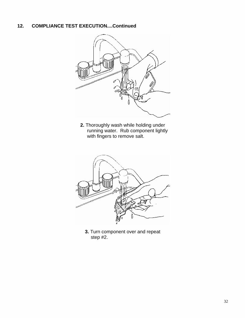
12. COMPLIANCE TEST EXECUTION....Continued
2. Thoroughly wash while holding under running water. Rub component lightly with fingers to remove salt.
3. Turn component over and repeat step #2.
32

12. COMPLIANCE TEST EXECUTION....Continued
4. After thoroughly washing, allow to dry for 24 hours before evaluation.
Evaluation for Corrosion: The hardware shall be free of ferrous or nonferrous corrosion that may be transferred, either directly or indirectly by means of webbing, to the restraint system’s occupant, or his/her clothing when the assembly is worn. Examine the hardware for such corrosion and record the results on the appropriate data sheet.
B.3.2 TEMPERATURE RESISTANCE (S209, S4.3(b), S5.2(b)) Subject three new specimens of all plastic or other nonmetallic buckle and
adjustment hardware to the accelerated service conditions test in accordance with ASTM D756-78, Procedure IV, omitting the weight and dimension measurements. Unlatch buckles, and condition the specimens as indicated in ASTM D756-78, Section 5, prior to and at the end of the test.
The hardware specimens shall not warp or otherwise deteriorate to cause the buckle
or other assembly to operate improperly. Examine the specimens for such deterioration, and record the results on the appropriate Data Sheet.
The three hardware specimens used in this test shall also be tested according to
applicable hardware tests outlined in this procedure.
33

34
12. COMPLIANCE TEST EXECUTION....Continued B.3.3 BUCKLE RELEASE ACCESS (S209, S4.3(d)(2), S5.2(d))
Follow the procedure given below for the appropriate buckle design, and record the results on the appropriate Data Sheet.
PUSHBUTTON BUCKLES Measure the linear dimensions of the surface designed for applying the release force,
and calculate the area of this surface to the nearest 0.3 square cm (0.05 square inch). This surface shall have a minimum area of 3.9 square cm (0.6 square inch), with a minimum linear dimension of 10 mm (0.4 inch).
LEVER-RELEASE BUCKLES Insert a cylinder 10 mm (0.4 inch) ± 0.5 mm (0.02 inch) in diameter and 38 mm (1.5
inches) ± 0.5 mm (0.02 inch) long in the actuation portion of the buckle release. The buckle shall permit insertion of this cylinder to at least the midpoint of the cylinder along the cylinder's entire length.
OTHER BUCKLE DESIGNS Attempt to actuate the buckle release using two adult fingers. The buckle shall have
adequate access for two or more adult fingers. B.3.4 ADJUSTMENT FORCE (S209, S4.3(e), S5.2(e)) Test three sets of adjustment hardware and webbing for the force necessary to
decrease the effective length of the assembly. The hardware previously used for the Corrosion Resistance of Temperature Resistance tests shall also be used for this test. With no load on the anchor end of the webbing, draw the webbing through the adjustment device at a rate of 508 mm per minute (mpm) (20 inches per minute (ipm)) ± 50 mpm (2 ipm). Precycle the webbing 10 times in the above manner, and then measure the maximum force to the nearest 0.1 kg (0.25 pound) after the first 25 mm (1.0 inch) of webbing movement. The force required to decrease the effective length of this assembly shall not exceed 5 kg (11 pounds). Record the results on the appropriate Data Sheet.
B.3.5 TILT-LOCK ADJUSTMENT (S209, S4.3(f), S5.2(f)) If the adjustment device is of a "tilt-lock" design, test three such devices for lock
angle. The hardware previously used for the Corrosion Resistance or Temperature Resistance tests shall also be used for this test. Orient the base of the adjustment mechanism and the anchor-end of the webbing in planes normal to each other. Draw the webbing through the adjustment mechanism in a direction to increase belt length at a rate of 508 mm (20 inches) ± 50 mm (2 inches) per minute while the plane of the base is slowly rotated in a direction to lock the webbing. When the webbing locks,

35
12. COMPLIANCE TEST EXECUTION....Continued
stop the rotation, but continue pulling on the webbing until there is a resistance of at least 9 kg (20 pounds). Measure the angle between the anchor-end of the webbing and the base of the adjustment mechanism to the nearest degree. The lock angle shall be not less than 30 degrees. Record the results on the appropriate Data Sheet.
B.3.6 BUCKLE LATCH AND PARTIAL ENGAGEMENT (S209, S4.3(g), S5.2(g)) Six buckle/tongue assemblies are tested for “as received” Partial Engagement and
then exposed as follows: three for Corrosion Resistance (B.3.1), and three for Temperature Resistance (B.3.2). After exposure the assemblies are then tested for Buckle Latch and Partial Engagement.
NOTE: Buckles with plastic components in either tongue or latch mechanism are not evaluated for partial engagement. A metal-to-metal buckle shall be examined to determine whether partial engagement is possible by means of any technique representative of actual use. If possible, the partial engagement test shall be conducted. If it is possible to insert a tongue in the inverted position, both positions must be evaluated for partial engagement.
B.3.6.1 AS RECEIVED PARTIAL ENGAGEMENT
B3.6.1.1 PARTIAL ENGAGEMENT
Anchor buckle in a rigid fixture. Manually insert tongue completely into buckle, release buckle and withdraw tongue only enough to induce partial engagement. Attach a cable and weight (22 N (4.9 lb.) total), to the tongue. In the case of a two-tongue buckle design, attach the weight to each tongue separately such that the force is equally distributed to both tongues. The alignment of buckle, tongue, and the weight must be parallel. Release the weight support slowly to allow the weight to be applied to the tongue in a direction parallel and away from the buckle. The weight must remove the tongue from the buckle in order to meet the “partial engagement release force” requirement. Measure the time required for the weight to remove the tongue from the buckle to within ± 3 seconds up to a maximum time of 60 seconds, ending the test. Perform the test 3 times on each of 3 assemblies and record the pass/fail results on each assembly. Repeat the tests with the tongue in an inverted position, as applicable. Record the results on the appropriate data sheet.
Only when directed by the COTR, the buckle shall be retested using the test procedure defined below in the following paragraph. The purpose of the retest is to obtain an average partial engagement release force.
Anchor buckle in some manner. Attach tongue to a force gauge by a flexible means such that the alignment of buckle, tongue, and gauge can be made parallel. Manually insert tongue completely into buckle and withdraw only enough to induce partial engagement. Remove tongue from buckle with force gauge and record the highest force reading as the “partial engagement release force.” Perform three readings per assembly. The average of the three readings will be used to determine

36
12. COMPLIANCE TEST EXECUTION....Continued
the partial engagement release force. Repeat tests with tongue in inverted position as applicable. Record the results on the appropriate Data Sheet.
B3.6.2 BUCKLE LATCH AND PARTIAL ENGAGEMENT FOLLOWING CORROSION
RESISTANCE (B.3.1) AND TEMPERATURE RESISTANCE (B.3.2) Following the corrosion resistance and temperature resistance tests, the six buckles (3 for the corrosion test and 3 for the temperature test) shall be tested for Buckle Latch per B3.6.2.1, and Partial Engagement per B3.6.2.2.
B.3.6.2.1 BUCKLE LATCH
Manually latch and unlatch six buckle assemblies (3 for the corrosion test and 3 for the temperature test) ten (10) times each. Then, mount the six buckles on a compressive cycling fixture. The fixture is such that one cycle will completely move a buckle’s release mechanism through its full range of motion and induces a force of 133 N (29.9 lb) ± 13 N (2.9 lb) at the travel limit of the mechanism. Operate the fixture at a rate of 30 cpm for a total of 200 cycles. Visually and functionally evaluate buckle assemblies following cycling and then perform the partial engagement test as specified in B.3.6.2.2.
B3.6.2.2 PARTIAL ENGAGEMENT
Perform partial engagement as per B.3.6.1.1. C. INSPECTION OF PHYSICAL FEATURES C.1 LABELING (S213, S5.5) Inspect the labels attached to the child restraint system and compare them with the
requirements of FMVSS 213, S5.5, listed on the appropriate Data Sheet. After the child restraint is installed, check whether certain required labels are visible in all recommended installation modes. Provide photographs of all labels on the child restraint system to show availability, legibility, and location. Include these photographs as part of the appropriate Data Sheet.

37
12. COMPLIANCE TEST EXECUTION....Continued C.2 INSTALLATION INSTRUCTIONS (S213, S5.6) Review the manufacturer's instructions for installation and use of the child restraint
system to verify that they include the information specified by S213, S5.6, and listed on the appropriate Data Sheet. Verify that storage provisions are available for these instructions on the child restraint itself.
C.3 INSTALLATION (S213, S5.3) Except for components designed to attach to a child restraint anchorage system, the
add-on child restraint shall have no means designed for attaching the system to the vehicle seat cushion or the vehicle seat back and no component (except belts) that is designed to be inserted between the vehicle seat cushion and vehicle seat back.
For harnesses labeled per S5.3.1(b)(1) through S5.3.1(b)(3) and Figure 12 of this
standard, the system shall be capable of meeting the requirements of this standard with a seat back mount.
Except for belt positioning seats, the add-on system shall also be capable of meeting
the requirements of this standard solely by means of a Type I seat belt assembly (lap belt) or by means of a lap belt plus one additional anchorage strap (tether) that is supplied with the system.
Each belt positioning seat shall be capable of meeting the requirements of this
standard solely by means of a Type II seat belt assembly (lap and shoulder belt). Except for harnesses, car beds, and belt positioning seats, the add-on system shall
be capable of meeting the requirements of this standard solely by means of a child restraint anchorage system (effective September 1, 2002).
For car beds, the system shall be designed to be installed on a vehicle seat so that
the car bed's longitudinal axis is perpendicular to a vertical longitudinal plane through the longitudinal axis of the vehicle. Indicate compliance and record any difficulties encountered during installation on the appropriate Data Sheet.
C.4 MINIMUM HEAD SUPPORT SURFACE (S213, S5.2.1) This section does not apply to car beds or to forward-facing child restraints whose
seating surface, when installed on the standard seat assembly, is low enough that the target point on either side of the appropriate dummy's head, when properly positioned in the restraint, is below the top of the standard seat assembly or vehicle seat (in the case of a built-in restraint). Indicate exemption, if appropriate, on the appropriate Data Sheet.
Other child restraint systems shall have a minimum back height, as specified below,
based on the manufacturer's recommended maximum weight for children using the restraint:

38
12. COMPLIANCE TEST EXECUTION....Continued
MAXIMUM WEIGHT BACK HEIGHT
Not more than 18 kg (40 pounds) 500 mm (19.7 inches)
More than 18 kg (40 pounds) 560 mm (22.0 inches)
Measure the height of the restraint back surface along the vertical centerline from the
seating surface to the top of the back surface. The padding on the seating surface may be depressed by the weight of the appropriate dummy in the seated position. Record the results on the appropriate Data Sheet.
The width of the back surface, at the height specified above, shall be at least 203 mm
(8 inches), or at least 152 mm (6 inches) if side wings at least 102 mm (4 inches) deep are also provided. Measure the depth of these side wings, if any, along a line perpendicular to the restraint back surface at the appropriate height from the seating surface as specified above. Record the results on the appropriate Data Sheet.
Measure the widest part of the back surface at the height specified above and at the forward plane made by the center of gravity targets located on each side of the dummy head of the appropriate size dummy when seated in the restraint as shown in Figure 14. However, the 6 year old child dummy is not used to determine applicability of or compliance with S5.2.1.1.

12. COMPLIANCE TEST EXECUTION....Continued
SEAT BACK WIDTH MEASUREMENT
TOP VIEW OF RESTRAINT
BACK WIDTH
SIDEWING
DEPTH
DUMMYHEAD
CG PLANE
FIGURE 14
The side wing depth shall be the remaining wing material forward of the dummy head CG plane.
In the case of a built-in child restraint, measure the height of the seat back as noted above. If the system includes a head rest also measure the seat height including the head rest in the fully down position. Record the results on the appropriate Data Sheet.
39

40
12. COMPLIANCE TEST EXECUTION....Continued C.5 BELT RESTRAINT (S213, S5.4.3) C.5.1 SNUG FIT OF BELTS (S213, S5.4.3.1) Each belt that is designed to restrain a child using the system shall be adjustable to
snugly fit any properly positioned child whose height and weight are within the ranges recommended by the manufacturer. Using the appropriate dummy, fasten and adjust the system's harness to fit properly around the dummy. If there is insufficient webbing to do so, the restraint system fails. If webbing is sufficient, note how much additional webbing is available to further lengthen and secure each harness segment. Record this information on the appropriate Data Sheet.
There is currently no test criterion for "snug fit" at the lower end of the size range.
Questionable cases should be indicated, however, under REMARKS on the appropriate Data Sheet for evaluation by COTR.
C.5.2 DIRECT RESTRAINT BELTS (S213, S5.4.3.2) Except for a child restraint system whose mass is less than 4.4 kg (9.7 pounds), no
belt that is designed both to restrain the child and to attach the restraint to the vehicle shall impose a load on the dummy resulting from the mass of either the child restraint system or the back of the standard seat assembly (for an add-on child restraint) or any part of the vehicle (for a built-in child restraint) during the Dynamic Impact Test. In addition, each Type I and the lap portion of a Type II belt system that is used to attach the system to the vehicle seat shall impose no loads on the child that result from the mass of the system, or the mass of the seat back (in the case of add-on systems) or from the mass of any part of the vehicle into which the child restraint is built (for built-in systems). To determine compliance with this requirement, verify whether the following conditions are met:
(1) The belt in question contacts the dummy for the purpose of restraint (2) the child restraint includes any rigid structure between the dummy and the
back of the standard seat assembly (3) The child restraint can slip such that the belt in question contacts the dummy
for the purpose of restraint If ALL THREE conditions apply, and the child restraint weighs more than 4.4 kg, the
restraint FAILS. If any one condition is NOT met, the restraint PASSES. Record the results on the appropriate Data Sheet.

41
12. COMPLIANCE TEST EXECUTION....Continued C.5.3 SEATING SYSTEM BELTS AND/OR SHIELDS (S213, S5.4.3.3) These requirements apply to child restraints that are designed for use by a child in a
seated position and that include belt restraints, with the specific exception of child harnesses. Also excluded are infant restraint systems that are designed to place the child in a rear-facing, semi-recumbent position instead of a seated position, and that are recommended only for children up to 10 kg. (22 lb.). For applicable seating systems, the following restraining systems shall be provided:
(1) Upper torso Either belts passing over each shoulder of the child or a fixed or movable
surface that complies with S5.2.2.1(c). (2) Lower torso Either a lap belt (angle with seating surface at anchorage point to be between
45 degrees and 90 degrees) or a fixed or movable surface that complies with S5.2.2.1(c).
(3) Crotch restraint For child restraints recommended for children over 10 kg (22 pounds), either a
crotch belt connectable to the lower torso restraint or a fixed or movable surface that complies with S5.2.2.1(c). Verify the existence of the above systems, and record the results on the appropriate Data Sheet.
C.5.4 CHILD HARNESSES (S213, S5.4.3.4) For child harnesses, the following restraining belts shall be provided: (1) Upper Torso -- Belts passing over each shoulder of the child (2) Lower Torso -- Lap and crotch belts (3) Belts to prevent any properly restrained child, whose height is within the range
recommended by the manufacturer, from standing on the vehicle seat. Verify the existence of the above belts, and record the results on the appropriate
Data Sheet.

42
12. COMPLIANCE TEST EXECUTION....Continued C.6 TORSO IMPACT PROTECTION (S213, S5.2.2) These requirements do not apply to car beds. For other child restraint systems, the
following surface area and curvature requirements apply. Remove padding for all curvature determinations, noting any difficulties on the appropriate Data Sheet.
For measurements that refer to dummy "shoulder height" or "torso depth," use the
following dimensions for the appropriate dummy, based on the manufacturer's recommended maximum weight for children using the restraint. These values are only provided for reference purposes to permit a determination of compliance with S5.2.2.1 (a) and S5.2.2.1 (b):
MAXIMUM WEIGHT
DUMMY
SHOULDER
HEIGHT
TORSO DEPTH
Under 10 kg (22 pounds)
12-month-old
307 mm
(12.1 inches)
109 mm
(4.3 inches)
10 kg (22 pounds) or more
3-year-old
368 mm
(14.5 inches)
133 mm
(5.25 inches) C.6.1 BACK SUPPORT SURFACE (S213, S5.2.2.1(a)) The surface provided for the support of the child's back shall be flat or concave and
have a continuous surface area of not less than 548 square cm (85 square inches). The area to be considered is the entire width of the restraint back surface below a height above the seating surface indicated above as "shoulder height" for the appropriate dummy. Measure this area, and record the results on the appropriate Data Sheet.
C.6.2 SIDE SUPPORT SURFACE (S213, S5.2.2.1(b)) Each surface provided for support of the side of the child's torso shall be flat or
concave and have a continuous surface of not less than 155 square cm (24 square inches) for systems recommended for children weighing 9 kg (20 pounds) or more, or 310 square cm (48 square inches) for systems recommended for children weighing less than 9 kg (20 pounds). "Torso" is defined as "the portion of the body of a seated anthropomorphic test dummy, excluding the thighs that lie between the top of the child restraint system seating surface and the top of the shoulders of the test dummy." The area to be considered as:
(1) BELOW a line perpendicular to the restraint back surface at a height above
the seating surface indicated above as "shoulder height" for the appropriate dummy, and

43
12. COMPLIANCE TEST EXECUTION....Continued (2) REARWARD of a line perpendicular to the seating surface at a distance
forward of the restraint back surface indicated above as "torso depth" for the appropriate dummy.
Measure this area, and record the results on the appropriate Data Sheet. C.6.3 FORWARD RESTRAINING SURFACE (S213, S5.2.2.1(c)) Each horizontal cross section of each surface designed to restrain forward movement
of the child's torso shall be flat or concave, and each vertical longitudinal cross section shall be flat or convex with a radius of curvature of the underlying structure of not less than 51 mm (2 inches). To determine contactable area of the forward restraining surface, the dummy may be “chalked” prior to the dynamic test and post test inspect the forward surface for transferred chalk. This surface shall be the contactable surface. Determine the curvatures, and record the results on the appropriate Data Sheet.
C.6.4 FORWARD FIXED OR MOVABLE SURFACES (S213, S5.2.2.2) For forward-facing child restraint systems, there shall be no fixed or movable surface
directly in front of the appropriate test dummy, when properly positioned in the restraint, and intersected by a horizontal line parallel to the Seat Orientation Reference Line (SORL) and passing through any portion of that dummy, except for surfaces that restrain the dummy when tested according to Dynamic Impact Test Configuration II (S213, S6.1.2(a)2). If such a surface exists, determination of compliance must be deferred pending results of the Dynamic Impact Test. If no such surface exists, the system complies. Indicate PASS or DEFERRED on the appropriate Data Sheet.
C.7 DELETED

44
12. COMPLIANCE TEST EXECUTION....Continued C.8 PROTRUSION LIMITATION (S213, S5.2.4) Any protrusion, padded or unpadded, on a rigid structure, other than belts or belt
hardware, that is contactable by any part of the appropriate dummy head or torso during the Dynamic Impact Test shall have a height above the immediately adjacent restraint system surface off not more than 9.525 mm (0.375 inch) and no exposed edge with a radius of less than 6.35 mm (0.25 inch). The areas to be considered include those identified in the section on Torso Impact Protection (C.6) with the addition of the surfaces directly forward of the dummy or directly rearward of the dummy and above its shoulders for restraints recommended for children weighing 10 kg (22 pounds) or more. This requirement does not apply to child harnesses consisting entirely of belt restraints.
Remove any padding in the applicable areas to make the measurements, and record
the maximum values encountered on the Data Sheet. C.9 ATTACHMENT TO CHILD RESTRAINT ANCHORAGE SYSTEM (S5.9)
(1) Each add-on child restraint system manufactured on or after September 1, 2002, other than a car bed, harness and belt positioning seat, shall have components permanently attached to the system that enable the restraint to be securely fastened to the lower anchorages of the child restraint anchorage system specified in FMVSS No. 225. The components must be attached such that they can only be removed by use of a tool, such as a screwdriver. In the case of rear-facing child restraints with detachable bases, only the base is required to have the components.
(2) In the case of each child restraint system that is manufactured on or after
September 1, 1999 and that has components for attaching the system to a tether anchorage, those components shall include a tether hook that conforms to the configuration and geometry specified in Figure 25.
(3) In the case of each child restraint system that is manufactured on or after
September 1, 1999 and that has components, including belt webbing, for attaching the system to a tether anchorage or to a child restraint anchorage system, the belt webbing shall be adjustable so that the child restraint can be tightly attached to the vehicle.
(4) Beginning September 1, 1999, each child restraint system with components that
enable the restraint to be securely fastened to the lower anchorages of a child restraint anchorage system, other than a system with hooks for attaching to the lower anchorages, shall provide either an indication when each attachment to the lower anchorages becomes fully latched or attached, or a visual indication that all attachments to the lower anchorages are fully latched or attached. Visual indications shall be detectable under normal daylight lighting conditions.
Inspect the restraint system for the applicable requirements and indicate the results on the appropriate Data Sheet.

45
12. COMPLIANCE TEST EXECUTION....Continued D. DYNAMIC TEST CONDITIONS AND PROCEDURES (S213, S6) Test a new specimen of the child restraint system according to the procedures below
in each possible combination of installation mode, adjustment position, and proper-use/"misuse" mode. Record the particular combination to be tested as well as the test configuration to be used on the appropriate Data Sheet.
D.1 TEST EQUIPMENT D.1.1 TEST CONDITIONS AND DEVICES (S213, S6.1.1) The test device used to evaluate the dynamic performance of the add-on child
restraint is the standard seat assembly securely attached to a dynamic test platform or impact sled. The standard seat assembly is described in Drawing Package NHTSA Standard Seat Assembly FMVSS No. 213, No. NHTSA-213-2003, dated June 3, 2003. The orientation should simulate a vehicle frontal impact. The standard seat has three seating positions. The forward direction of the standard seat is defined by the Seat Orientation Reference Line (SORL), which is the horizontal line through point Z as illustrated in Figure 15. Additional belt anchor points and forward dummy excursion limits for dynamic test compliance are illustrated in Figure 16.
Figures 15a and 16a illustrate the locations of the lower anchor bars, belt anchor points, and forward excursion limits for the universal child restraint anchorage system applicable to add-on child restraint systems other than belt positioning booster seats.
The standard seat assembly is covered by a seat cushion. The seat cushion is constructed of elastic-backed automotive vinyl on the upper surface, which is in contact with the child restraint, backed by a thin layer of nylon-impregnated vinyl (MIL SPEC 43006, Type 1, Class 2, Form 1, 350 lb. Ripping strength). The nylon-impregnated vinyl extends around the top of seam of the cover and is cross-stitched to the automotive vinyl on the seating surface.
The test device for built-in child restraint systems is either the specific vehicle shell or the specific vehicle.
SPECIFIC VEHICLE SHELL
A. The specific vehicle shell, if selected for testing, is mounted on a dynamic test platform so that the longitudinal center line of the shell is parallel to the direction of the test platform travel and so that movement between the base of the shell and the platform is prevented. Adjustable seats are in the adjustment position midway between the forward-most and rearmost positions, and if separately adjustable in a vertical direction, are at the lowest position. If an adjustment position does not exist midway between the forward-most and rearmost position, the closest adjustment position to the rear of the midpoint is used. Adjustable seat backs are in the manufacturer’s nominal design riding position. If such a position is not specified, the seat back is positioned so that

46
12. COMPLIANCE TEST EXECUTION....Continued the longitudinal centerline of the child test dummy’s neck is vertical, and if an
instrumented test dummy is used, the accelerometer surfaces in the dummy’s head and thorax, as positioned in the vehicle, are horizontal. If the vehicle seat is equipped with adjustable head restraints, each is adjusted to its highest adjustment position.
B. The platform is instrumented with an accelerometer and data processing
system having a frequency response of 60 Hz channel class as specified in Society of Automotive Engineers Recommended Practice J211 MARCH95 “Instrumentation for Impact Tests.” The accelerometer sensitive axis is parallel to the direction of test platform travel.
SPECIFIC VEHICLE
For built-in child restraint systems, an alternate test device is the specific vehicle into which the built-in system is fabricated. The following test conditions apply to this alternate test device.
A. The vehicle is loaded to its unloaded vehicle weight plus its rated cargo and
luggage capacity weight, secured in the luggage area, plus the appropriate child test dummy and, at the vehicle manufacturer’s option, an anthropomorphic test dummy which conforms to the requirements of subpart B or subpart E of part 572 of this title for a 50th percentile adult male dummy placed in the front outboard seating position. If the built-in child restraint system is installed at one of the seating positions otherwise requiring the placement of a part 572 test dummy, then in the frontal barrier crash specified in (c), the appropriate child test dummy shall be substituted for the part 572 adult dummy, but only at that seating position. The fuel tank is filled to any level from 90 to 95 percent of capacity.
B. Adjustable seats are in the adjustment position midway between the forward-
most and rearmost position, and if separately adjustable in a vehicle direction, are at the lowest position. If an adjustment position does not exist midway between the forward-most and rearmost positions, the closest adjustment position to the rear of the midpoint is used.
C. Adjustable seat backs are in the manufacturer’s nominal design riding position.
If a nominal position is not specified, the seat back is positioned so that the longitudinal center line of the child test dummy’s neck is vertical, and if an anthropomorphic test dummy is used, the accelerometer surfaces in the test dummy’s head and thorax, as positioned in the vehicle, are horizontal. If the vehicle is equipped with adjustable head restraints, each is adjusted to its highest adjustment position.
D. Movable vehicle windows and vents are, at the manufacturer’s option, placed
in the fully closed position.

47
12. COMPLIANCE TEST EXECUTION....Continued
E. Convertibles and open-body type vehicles have the top, if any in place in the closed passenger compartment configuration.
F. Doors are fully closed and latched but not locked. SLED SEAT FOAM
Before conducting a Dynamic Impact Test, measure the force-deflection characteristics of all four foam inserts used in the standard seat. Using the test methodology and apparatus described in ASTM Standard D1564-71 “Standard Method of Testing Flexible Cellular Matherials-Slab Urethane Foam,” determine the load required to produce a 25% compression of the foam thickness. To be suitable for use in compliance testing, the foam inserts shall compress 25% under the following load limits:
51 mm (2-inch) thick foam: 20.4 to 24.9 kg (45 to 55 lbs) 102 mm (4-inch) thick foam: 9.5 to 12.2 kg (21 to 27 lbs) If a foam insert has already been used in a Dynamic Impact Test, allow a minimum of
twelve hours recovery time before measuring the force-deflection characteristics. Also inspect each used foam insert for damage or permanent deformation, and replace any insert judged to be defective.
TYPE I AND TYPE II BELT WEBBING
The webbing used for both the type I and type II belts are five-panel polyester webbing that complies with FMVSS 209 Seat Belt Assemblies. A new belt is used for each test performed.