us navy support equipment
TRANSCRIPT

CHAPTER 9
SUPPORT EQUIPMENT
INTRODUCTION
This chapter identifies support equipment (SE)used to handle, service, load, test, and maintain aircraft.As an Airman Apprentice, you will be required tooperate SE. Some SE is used both ashore and afloat,while other SE is used only ashore or only afloat. TheSE division of the AIMD is tasked with maintainingSE. Principal users of SE are the squadron linedivision, the base operations line division, and the airdepartment aboard aircraft carriers.
TYPES OF EQUIPMENT
LEARNING OBJECTIVE: Identify thepurpose and function of the types of supportequipment, to include operation, maintenance,hazards, and carrier air and shore-basedoperations.
There are two types of support equipment—aircrafthandling equipment and aircraft servicing equipment.The following text discusses these various types ofsupport equipment.
HANDLING EQUIPMENT
Aircraft handling equipment consists of towtractors; crash and salvage equipment, to includefire-fighting vehicles and maintenance cranes; forklifttrucks; and flight deck scrubbers.
Tow Tractors
Various tow tractors in the Navy inventory arediscussed in the following text.
A/S32A-30 AIRCRAFT GROUND SUPPORTEQUIPMENT TOWING TRACTOR.—TheA/S32A-30 tow tractor (fig. 9-1) is a 6-cylinder,gasoline-powered, four-wheel, heavy-duty vehicle witha three-speed transmission. The tractor frame is awelded steel one-piece unit. It is equipped withhydraulically actuated front disc brakes and drum-typebrakes on the rear wheels. A hydraulically assistedsteering unit provides steering to the front wheels. Thetractor employs a 12-volt electrical system to supplypower for lighting, starting, horn, and instrumentoperation. It comes equipped with two seats—onedriver and one passenger—mirrors, front and reartowing couplers (pintles), tie-down fittings and lifting
attachments. It can be fitted with a fully enclosed cab. Itis designed to tow aircraft servicing equipment, workstands, and armament handling equipment.
A/S32A-30A AIRCRAFT GROUND SUPPORTEQUIPMENT TOWING TRACTOR.—TheA/S32A-30A tow tractor (fig. 9-2) is a 4-cylinder,diesel engine, (dual wheel) rear-wheel-drive tractorwith a 40,000-pound towing capacity. It comes with athree-speed automatic transmission, hydraulic brakeson front and rear wheels, conventional power steeringwith power assist to the front wheels, and employs aconventional 12-volt electrical system with battery andalternator to supply power for the lights, horn, startermotor, ignition, and instruments.
9-1
ANF0901
Figure 9-1.—A/S32A-30 aircraft ground support equipmenttowing tractor.
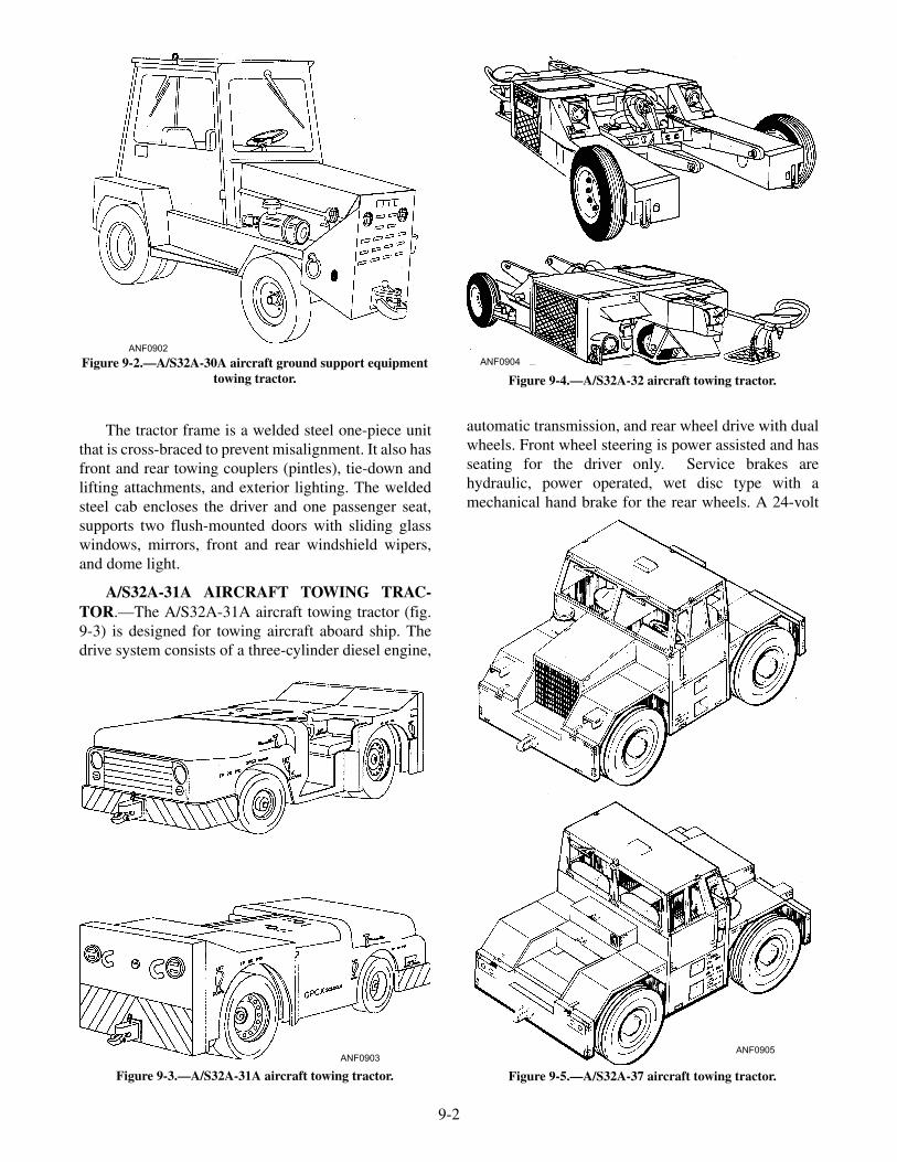
The tractor frame is a welded steel one-piece unitthat is cross-braced to prevent misalignment. It also hasfront and rear towing couplers (pintles), tie-down andlifting attachments, and exterior lighting. The weldedsteel cab encloses the driver and one passenger seat,supports two flush-mounted doors with sliding glasswindows, mirrors, front and rear windshield wipers,and dome light.
A/S32A-31A AIRCRAFT TOWING TRAC-TOR.—The A/S32A-31A aircraft towing tractor (fig.9-3) is designed for towing aircraft aboard ship. Thedrive system consists of a three-cylinder diesel engine,
automatic transmission, and rear wheel drive with dualwheels. Front wheel steering is power assisted and hasseating for the driver only. Service brakes arehydraulic, power operated, wet disc type with amechanical hand brake for the rear wheels. A 24-volt
9-2
ANF0902
Figure 9-2.—A/S32A-30A aircraft ground support equipmenttowing tractor.
ANF0903
Figure 9-3.—A/S32A-31A aircraft towing tractor.
ANF0904
Figure 9-4.—A/S32A-32 aircraft towing tractor.
ANF0905
Figure 9-5.—A/S32A-37 aircraft towing tractor.

electrical system provides starting, lighting, andinstrumentation. Front and rear mounted pintles areused for aircraft towing. A universal jet-engine startunit mounts to the rear of the tractor.
A/S32A-32 AIRCRAFT TOWING TRAC-TOR.—The A/S32A-32 Aircraft Towing Tractor (fig.9-4), also called "The Spotting Dolly," is designed totow, turn, and position aircraft within the confines of anaircraft carrier hangar deck. It is powered by athree-cylinder diesel engine, which drives two mainhydraulic pumps. The hydraulic pumps supply fluid todrive motors that turn two open-chain reduction drivesvia two gearboxes at each main wheel, which operatesindependently. A mechanical wheel clutch handle isused to engage or disengage the drive wheels, enablingthe tractor to pivot on a caster wheel around its centerwithin a zero turning radius. A Joystick Control, next tothe operator's seat, is an electromechanical device usedto control the speed and direction of the spotting dolly'smovement. The lift cylinder, which raises and lowersthe lifting arms, and two spread cylinders, which keepthe arms pinned against the aircraft nose gear, arepowered by an auxiliary hydraulic pump. Several pairs
of axle pins that engage both sides of the nosewheel arecarried on the tractor and fit a variety of aircraft.
A/S32A-37 AIRCRAFT TOWING TRAC-TOR.—The A/S32A-37 aircraft towing tractor (fig.9-5) is an inline, 6-cylinder, diesel-powered,liquid-cooled, 4-wheel drive vehicle used to moveheavy, shore-based aircraft. The full power shifttransmission has six forward and three reverse speeds.The tractor's front wheels are steered by two hydrauliccylinders, and all wheels are equipped withhydraulically powered disc brakes. A two-seat, heated,enclosed cab with removable doors is provided foroperator comfort in all weather. Two 12-volt batteries,24-volt alternator, electrical system provides power forlighting, instrumentation, control panels, starter motor,transmission control, switches, wiper/washer motor,and heater/defroster. The tractor is capable of 35,000pounds of drawbar pull with the traction ballast kitinstalled.
A/S32A-42 AIRCRAFT MID-RANGE TOWVEHICLE.—The A/S32A-42 aircraft mid-range towvehicle (fig. 9-6) is a 4-cylinder, diesel-powered,
9-3
ANF0906
JACK STANDLOCATION
(ON FRAME)
JACK STANDLOCATION
(ON FRAME)
LIFT/TIE-DOWN
LOCATION
LIFT/TIE-DOWN
LOCATIONS
LIFT/TIE-DOWN
LOCATION
Figure 9-6.—A/S32A-42 aircraft mid-range tow vehicle.

3-speed automatic transmission, liquid cooled,rear-wheel-drive tractor designed for towing aircraftweighing up to 100,000 pounds. The frame is awelded-steel one-piece unit, with cross brace, powerassisted front wheel steering, hydraulic boost powerdisc brakes, and a conventional 12-volt electricalsystem, with alternator, to supply power for the lightsand accessories, horn, starter motor, ignition, andinstruments. Front and rear tow couplers (pintles) andtie-down attachments are provided.
Crash and Salvage Equipment
Various salvage and maintenance cranes,fire-fighting vehicles, and Twinned Agent Unit(TAU-2H) extinguishers are discussed in the followingtext.
A/S32A-35A (CVCC) AIRCRAFT CRASHHANDLING AND SALVAGE CRANE.—TheA/S32A-35A aircraft crash handling and salvage crane(fig. 9-7) is a self-propelled, four-wheel drive,six-cylinder, liquid-cooled, turbocharged, dieselelectric-powered vehicle mounted on six pneumaticrubber tires. The ac generator is directly coupled to theengine and provides power to the drive motors,luff/hoist winch motor, auxiliary hoist/counterweightwench motor and motor control systems. A hydraulic
pump is directly coupled to the engine and providesfluid flow for steering, self-adjusting service brakes,and winch brake control. Vehicle steering isaccomplished by hydraulic cylinders, which connect tothe rear axle and main frame. The front and rear axlespivot in opposite directions, allowing significantturning capability. The crane main hoist has a static liftcapacity of 75,000 pounds and the crane auxiliary hoisthas a lift capacity of 10,000 pounds.
The crane is capable of operating aboard ship ininclement weather. It is designed to be stowed on theflight deck of an aircraft carrier, where it will beexposed to extreme weather and corrosive conditions.In service, the crane will lift crashed/damaged aircraftfrom various locations and attitudes and move loads ona rolling and pitching ship to a safe parking zone on theflight deck.
A/S32A–36A (AACC) AIRCRAFT CRASHHANDLING AND SALVAGE CRANE.—TheA/S32A-36A aircraft crash handling and salvage crane(fig. 9-8) is a six-wheel, four-wheel drive,liquid-cooled, turbocharged, diesel, electric-powered,self-propelled vehicle. Steering is hydraulicallycontrolled via the front and rear wheels. Mid and rearaxle drive motors provide traction power and has a
9-4
ANF0907
Figure 9-7.—A/S32A-35A (CVCC) aircraft crash handling and salvage crane.

six-wheel, self-adjusting air/hydraulic brake systemincorporated. Rear and mid dc electric drive motorsprovide power for crane travel, while a separate dcelectric motor provides power to the main hoist controlor boom luff control. The crane has a maximum liftcapability of 70,000 pounds and can be operated fromthe cab or by a remote pendant control.
The crane is capable of operating aboard ship ininclement weather. It is designed to be stowed on theflight deck of an aircraft amphibious assault ship,where it will be exposed to extreme open-sea weatherconditions and the corrosive effects of a saltwateratmosphere. In service, the crane will liftcrashed/damaged aircraft from various locations andattitudes and move loads on a rolling and pitching shipto a safe parking zone on the flight deck.
A/S32P-25 SHIPBOARD FIRE-FIGHTINGVEHICLE.—The P-25 shipboard fire-fighting vehicle(figs. 9-9 and 9-10) is a four-wheel (two-wheel drive),six-cylinder, turbocharged, liquid-cooled, 24-volt,diesel-powered vehicle with a hydrostatic drive system
that transmits power to the rear wheels. Steering ispreformed by a single hydraulic cylinder and tie-rodassembly that controls the front wheels. Dynamicvehicle braking is provided by the hydrostatic drivesystem. When the accelerator is released, the brakesautomatically engage. Separate tanks within thevehicle chassis carry 750 gallons of water and 55gallons of AFFF (Aqueous Film-Forming Foam).Three 20-pound fire extinguishers containing Halon1211 (halogenated extinguishing agent) are stored onthe right side of the vehicle. One nursing lineconnection on each side of the vehicle provides AFFFmixture from the ship's system directly to the vehicle'swater pump.
The vehicle has seating for a crew of two. Thedriver compartment is located at the left forward end ofthe vehicle and contains the main control panel foractivating the fire-fighting systems. AFFF can besprayed from both the forward turret nozzle andhandline hose reel nozzle. These nozzles operateindependently and can be used simultaneously to makethis vehicle ready for fire-fighting duty.
9-5
ANF0908
Figure 9-8.—A/S32A-36A (AACC) amphibious assault ship crane.

9-6
ANF0909
AFFF HYDRAULICTANK ACCESS DOOR
TOP ENGINEACCESS PANELS
COOLANTRECOVERY BOTTLE
ACCESS DOOR
NURSINGCONNECTION
FUELFILL
FUELTANK
FOAM-FILLEDTIRES
DRIVER’SSTATIONTIEDOWNS
LOWERPROPORTIONINGSYSTEM ACCESS
FIREFIGHTER’SSTATION
WATER TANKFILL
BRAKE RELEASEHAND PUMP
ANF0909
AFFF HYDRAULICTANK ACCESS DOOR
TOP ENGINEACCESS PANELS
COOLANTRECOVERY BOTTLE
ACCESS DOOR
NURSINGCONNECTION
FUELFILL
FUELTANK
FOAM-FILLEDTIRES
DRIVER’SSTATIONTIEDOWNS
LOWERPROPORTIONINGSYSTEM ACCESS
FIREFIGHTER’SSTATION
WATER TANKFILL
BRAKE RELEASEHAND PUMP
Figure 9-9.—A/S32P-25 shipboard fire-fighting and rescue vehicle—major assemblies and components (left side).
ANF0910
UPPERPROPORTIONINGSYSTEM ACCESS
MAINCONTROL
PANEL
TURRET
PORTABLEHALON
BOTTLES (3)
HANDLINEHOSE REEL
AFFFTANK FILL
WATER TANK FILL(QUICK FILL)
NURSINGCONNECTION
RIGHT SIDEENGINE ACCESS
DOOR
FILTERACCESS
DOOR
TIEDOWNS
REARENGINEACCESS
DOOR
KNEELPLATE
DIESELENGINE
COMPARTMENT
HYDRAULICTANK FILL (2)
EXHAUST
LIFTING/TIEDOWN
BATTERIES
Figure 9-10.—A/S32P-25 shipboard fire-fighting and rescue vehicle—major assemblies and components (right side).
TWINNED AGENT UNIT (TAU-2H).—TheTwinned Agent Unit (TAU-2H) extinguisher (fig. 9-11)is a dual-agent apparatus that is designed primarily forextinguishing class B fires and is employed aboard shipand shore facilities normally located at hot refuelingsites, or it can be vehicle-mounted. The TAU-2H is aself-contained unit with a framework with two agenttanks—one containing 86 gallons of AFFF premixed
solution and the other containing 200 pounds of Halon1211. The system permits use of the fire-fighting agentseither separately or simultaneously. The TAU-2Hemploys a noncollapsible dual hose line encased in afire-resistant cotton jacket. The twinned hose line isnormally stowed in a rack or mounted on a reel. Thefire-extinguishing agents are propelled by nitrogen,which is supplied by one 2700 psi pressurized cylinderthat is regulated to 200 psi and mounted on theframework. The twinned nozzles on the handline expelthe fire-fighting agents. The Halon nozzle is equippedwith a low-reaction discharge tip. The AFFF nozzle isequipped with an aspirating tip. Duel pistol griphandles and triggers operate the shutoff valves.Extinguishment is obtained by applying agents in asweeping motion, using the chemical agent Halon 1211to gain initial extinguishment, followed by applicationof AFFF to blanket the combustible liquid and precludereignition.
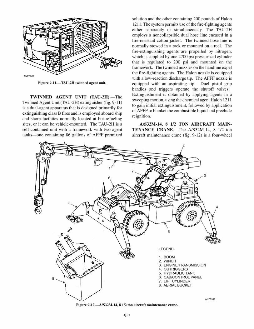
A/S32M-14, 8 1/2 TON AIRCRAFT MAIN-TENANCE CRANE.—The A/S32M-14, 8 1/2 tonaircraft maintenance crane (fig. 9-12) is a four-wheel
9-7
ANF0911
Figure 9-11.—TAU-2H twinned agent unit.
ANF0912
LEGEND
1. BOOM2. WINCH3. ENGINE/TRANSMISSION4. OUTRIGGERS5. HYDRAULIC TANK6. CAB/CONTROL PANEL7. LIFT CYLINDER8. AERIAL BUCKET
1
4
6
7
2
3
4
5
8
Figure 9-12.—A/S32M-14, 8 1/2 ton aircraft maintenance crane.

drive, four-wheel steering, four-cylinder, dieselpowered vehicle with a main transmission, drive axles,and a hydraulic craning circuit. The hydraulic craningcircuit consists of a hydraulic pump and motors, valves,cylinders, piping, and a superstructure that revolves 360degrees and can lift and move loads from one locationto another. A 24-volt electrical circuit provides powerfor starting, lighting, instrumentation, andelectrohydraulics. The crane's primary purpose is toremove and replace aircraft components in support ofscheduled and unscheduled maintenance. This includesengines, transmissions, propellers, engine modules,and rotor blades.
Forklift Truck
The forklift truck (fig. 9-13) is a cantilever-typeindustrial truck, either gasoline, diesel (shipboard use),or electrically operated, and is used in the handling andlifting of palletized unit loads. It contains verticaluprights and an elevator backplate equipped with twoor more forks of sufficient length and thickness forlifting pallets. The forklift truck is probably the mostwidely used power-driven piece of material-handlingequipment for palletized loads aboard ship and in Navyindustrial supply warehouses. When not on a hardsurface, a forklift truck should have pneumatic tires tooperate efficiently. Public works maintains forklifts on
shore stations. Aboard carriers, the support equipmentdivision of AIMD performs the maintenance.
Flight Deck Scrubber
The fight deck scrubber (fig. 9-14) is designed tospray a cleaning solution onto the flight and hangardecks, scrub the deck, and recover the residual solutionand debris for disposal. It consists of the debris hopperhousing, two opposed rotation cylindrical brushes, asolution and recovery tank, and a vacuum recoverysystem and rear squeegee. Those are mounted on adriver-operated, four-cylinder, two-wheel drive, dieselengine power drive train. The purpose of having flightdeck scrubbers aboard ship is to achieve and maintain ahigh degree of deck cleanliness, which contributes to areduction of aircraft engine Foreign Object Damage(FOD) and provides better traction, thereby improvingpersonal safety during flight operations.
SERVICING EQUIPMENT
Servicing equipment provides compressednitrogen or air, electrical and hydraulic power, andair-conditioning for aircraft functions while the aircraftis on the ground. Mobile electrical power plants(MEPPs) supply electrical power for aircraft testingand maintenance and operate on shore stations andaboard aircraft carriers. MEPPs have high
9-8
ANF0913
Figure 9-13.—Forklift truck.
maneuverability and mobility. On shore stations,MEPPs may be self-propelled or trailer-mounted andrequire towing. The following text describes some ofthe servicing units you will see in the aviationcommunity.
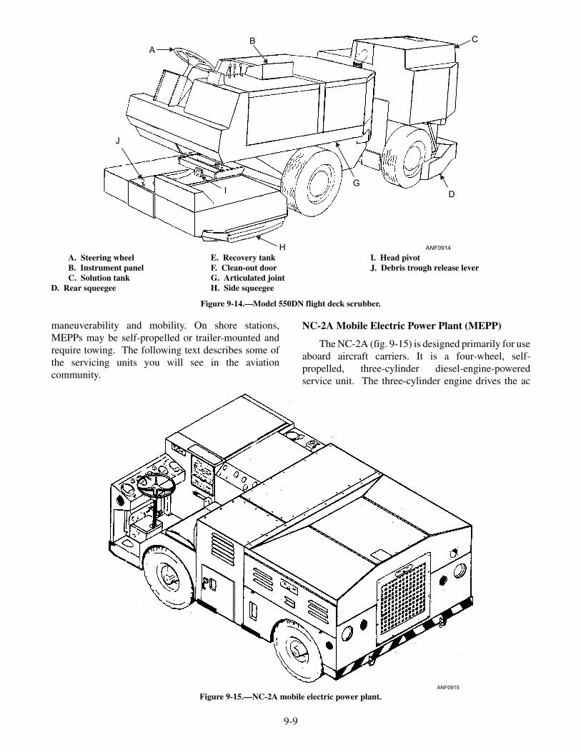
NC-2A Mobile Electric Power Plant (MEPP)
The NC-2A (fig. 9-15) is designed primarily for useaboard aircraft carriers. It is a four-wheel, self-propelled, three-cylinder diesel-engine-poweredservice unit. The three-cylinder engine drives the ac
9-9
ANF0914
AB C
D
G
J
I
HA. Steering wheelB. Instrument panelC. Solution tank
D. Rear squeegee
E. Recovery tankF. Clean-out doorG. Articulated jointH. Side squeegee
I. Head pivotJ. Debris trough release lever
Figure 9-14.—Model 550DN flight deck scrubber.
ANF0915
Figure 9-15.—NC-2A mobile electric power plant.

and dc generators through a speed increasingtransmission. The front axle is driven by a 28-volt dc,reversible, variable speed motor and steered by the tworear wheels, and is easy to maneuver in congestedareas. The ac and dc power cables are stored in acompartment near the driver. They deliver115/200-volt, 3-phase, 400-hertz ac, and 28 volts of dcto the aircraft. All controls, both propulsion andelectrical power, are located on three panels located infront and to the right of the operator's seat. The MEPP isdesigned for air transport and is provided with tie-downrings and forklift channels.
NC-8A Mobile Electric Power Plant (MEPP)
The NC-8A (fig. 9-16) is a four-wheel, electricallypropelled, front-wheel steering, rear-wheel drive,
four-cylinder, liquid-cooled, diesel-engine-poweredservice unit. It provides 115/200-volt, 3-phase,400-hertz ac and 28 volts of dc electrical power forstarting, servicing, and maintenance of rotary andfixed-wing aircraft. The ac and dc power cables arelocated and stored on spring-loaded reels in acompartment in the rear of the vehicle. All propulsionand electrical controls are located on two panels in thedriver's compartment. This MEPP is used primarily onshore stations, but it can also be operated aboard ship.
NC-10C Mobile Electric Power Plant (MEPP)
The NC-10C (fig. 9-17) is a trailer-mounted,self-contained power plant designed for shore-basedfacilities. It supplies electrical power for servicing,starting, and maintaining aircraft. The six-cylinder,
9-10
ANF0916
Figure 9-16.—NC-8A mobile electric power plant.
ANF0917
Figure 9-17.—NC-10C mobile electric power plant.

two-cycle, water-cooled, diesel engine andcomponents, ac and dc generators, are enclosed in aremovable steel housing. The ac and dc power cablesare stored on spring-loaded reels next to the controlpanel and deliver 115/200-volt, 3-phase, 400-hertz acand 28-volt dc electrical power. A tow bar for towingand steering, tie-down rings, fire extinguisher, hingeddoors for operation, and manual hand brake areprovided.
MMG-1A Mobile Electric Power Plant (MEPP)
The MMG-1A (fig. 9-18) is a small, compact,trailer-mounted, electric motor-driven generator set. Itprovides 155/200-volt, 3-phase, 400-hertz ac power,
and 28-volt dc power for aircraft maintenance,calibration, and support. Operation of the unit requiresa 3-phase, 60-hertz, 220- or 440-volt external powersource. The 30-foot input and output cables are stowedin compartments in the rear and left front side of theunit. It is used both aboard ship and ashore. The MEPPis not self-propelled and must be towed or manuallymoved. The 4-wheel trailer is equipped with tie-downrings, pneumatic tires, a mechanical hand brake, and atow bar for towing and steering.
A/M47A-4 Jet Aircraft Start Unit
The A/M47A-4 jet aircraft start unit (fig. 9-19) is a4-wheel, trailer-mounted, transportable gas turbine air
9-11
ANF0918
Figure 9-18.—MMG-1A mobile electric power plant.
ANF0919
Figure 9-19.—A/M47A-4 trailer-mounted jet aircraft start unit.

compressor (GTC) used to provide air and electricalpower for starting aircraft jet engines. The start unitcontains all the components and fuel supply necessaryfor independent operation. The start unit requiresmanual start initiation/stop and manual air selection.Once started, an engine control system regulates start,acceleration, and engine operation. Air start hoses andelectrical cables are provided. This unit is used aboardshore stations.
A/S47A-1 Jet Aircraft Start Unit
The A/S47A-1 jet aircraft start unit (fig. 9-20) is atractor-mounted, self-contained, mobile aircraft turbineengine air start unit. The air start unit enclosure consistsof a control panel, enclosure assembly, gas turbine aircompressor (GTC), stowage rack for the air start hose,and turbine support and mounting assembly. Except forfuel and electrical power (supplied by the tractor), theenclosure contains all systems necessary for gas turbineengine operation. This unit is used aboard ship and onshore stations.
WARNINGHot exhaust from a jet aircraft start unit is a
serious hazard when operating in close proximityto aircraft, aircraft components, fuel, weapons,equipment, and personnel.
You must take extra special precautions as to wherea gas turbine compressor (GTC) is positioned during
operation, especially aboard ship where aircraft areparked closely together. High volume air pressure,extreme exhaust temperatures, jet intake suction, highnoise levels, and unqualified operator's are all potentialhazards.
A/M27T-5 Hydraulic Portable Power Supply
The A/M27T-5 hydraulic portable power supply(fig. 9-21) is a self-contained, single-system, hydraulicpumping unit powered by a three-cylinder, two-cycle,diesel engine with a rated capacity of 20 gpm at 3,000psi and 10 gpm at 5,000 psi. During normal operationthe diesel engine runs at speeds up to 2,500 rpm. TheA/M27T-5 engine operates on JP-5 (jet fuel) or dieselfuel, and the hydraulic reservoir holds 20 gallons.Pressure and return hydraulic hoses, a tow bar, tie-downrings, and a manual hand brake are provided.
A/M27T-7 Hydraulic Portable Power Supply
The A/M27T-7 hydraulic portable power supply(fig. 9-22) is similar in operation to the A/M27T-5except for its source of power. The A/M27T-7 ispowered by a 50 horsepower electric motor. A 50-footpower cable is provided for connection to an external440-volt, 3-phase, 60-hertz power source and can be setup to operate on a 220-volt source. The hydraulicreservoir holds 16 gallons and is equipped with a fluidlevel sight gauge. Pressure and return hydraulic hoses, atow bar, tie-down rings, and a manual hand brake areprovided.
9-12
ANF0920
Figure 9-20.—A/S47A-1 tractor-mounted jet aircraft start unit.

9-13
ANF0921
Figure 9-21.—A/M27T-5 hydraulic portable power supply.
ANF0922
Figure 9-22.—A/M27T-7 hydraulic portable power supply.
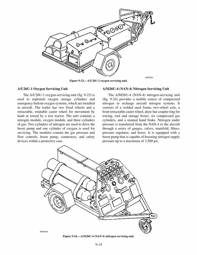
A/U26U-1 Oxygen Servicing Unit
The A/U26U-1 oxygen-servicing unit (fig. 9-23) isused to replenish oxygen storage cylinders andemergency bailout oxygen systems, which are installedin aircraft. The trailer has two fixed wheels and aretractable, rotatable caster wheel for movement byhand or towed by a tow tractor. The unit contains anitrogen module, oxygen module, and three cylindersof gas. Two cylinders of nitrogen are used to drive theboost pump and one cylinder of oxygen is used forservicing. The modules contain the gas pressure andflow controls, boost pump, connectors, and safetydevices within a protective case.
A/M26U-4 (NAN-4) Nitrogen Servicing Unit
The A/M26U-4 (NAN-4) nitrogen-servicing unit(fig. 9-24) provides a mobile source of compressednitrogen to recharge aircraft nitrogen systems. Itconsists of a welded steel frame, two-wheel axle, afront retractable caster wheel, draw bar coupler ring fortowing, tool and storage boxes, six compressed gascylinders, and a manual hand brake. Nitrogen underpressure is transferred from the NAN-4 to the aircraftthrough a series of gauges, valves, manifold, filters,pressure regulator, and hoses. It is equipped with aboost pump that is capable of boosting nitrogen supplypressure up to a maximum of 3,500 psi.
9-14
ANF0923
Figure 9-23.—A/U26U-1 oxygen servicing unit.
ANF0924
Figure 9-24.—A/M26U-4 (NAN-4) nitrogen servicing unit.

TMU 70/M Oxygen Storage Tank
The TMU 70/M (fig. 9-25) is a completelyself-contained unit composed of three majorcomponents: a 50-gallon storage tank, a 15-litertransfer tank, and a system of transfer lines and controlvalves. The three components are permanentlymounted on a portable three-wheel trailer. The trailer isequipped with a manually operated parking brakesystem and retractable caster wheel. The storage andtransfer tanks have liquid level, pressure gauges, andpressure relief devices.
Mobile Air-Conditioning Units
Most modern aircraft are crammed with electronicequipment that generates tremendous amounts of heatand makes air conditioning a requirement in the air and
on the ground. Air conditioning is normally providedby an onboard system, but the aircraft engines must beoperating for the system to work. When on the ground,electronic equipment must run for long periods of timefor maintenance, testing, or calibration. Therefore,some other means of air conditioning is needed, andthat is the purpose of mobile air-conditioning units.
A/M32C-17 AIR-CONDITIONER.—The A/M32C-17 air-conditioner (fig. 9-26) is a mobile, four-wheel,trailer-mounted, self-contained, six- cylinder dieselpowered unit that provides filtered air for cooling,dehumidifying, or ventilating of aircraft electronicequipment or cockpit/cabin areas during groundmaintenance. The air-conditioning components arecontained in a metal panel housing and assembled intoa refrigeration system, a ventilation system, a hydraulic
9-15
ANF0925
Figure 9-25.—TMU 70/M low-loss, closed-loop, liquid oxygen storage tank.
ANF0926
Figure 9-26.—A/M32C-17 air-conditioner.
9-16
ANF0927
Figure 9-27.—A/M32C-21 air-conditioner.
ANF0928
VIEW(A). AIRCRAFT AXLE JACKS
VIEW(B). AIRCRAFT TRIPOD JACKS
Figure 9-28.—Hydraulic jacks, (A) Aircraft axle jacks; (B) Aircraft tripod jacks.
system, and associated sensing and controlcomponents. The trailer has towing and steeringcapabilities and its own braking system. A collapsibleair ducting hose connects to the aircraft and providesconditioned air.
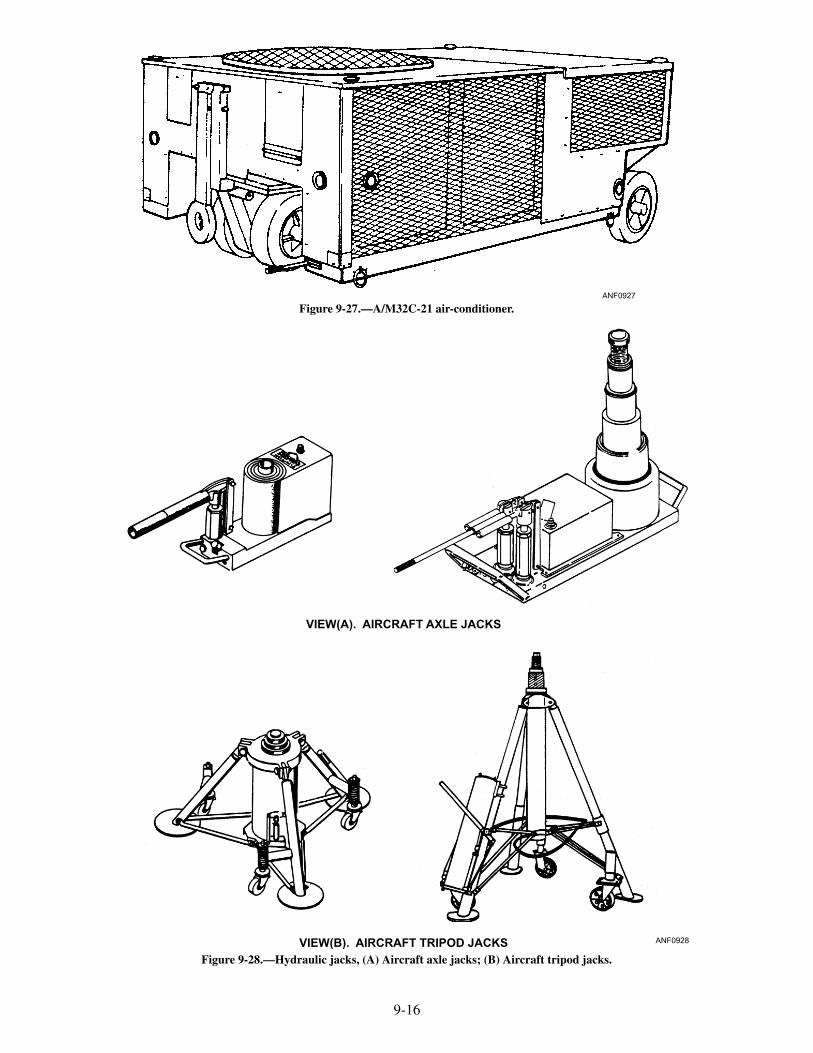
A/M32C-21 AIR CONDITIONER.—TheA/M32C-21 air-conditioner (fig. 9-27) is a mobile,four-wheel, trailer-mounted, electrically powered,self-contained unit powered by a 30-horsepower,440-volt, 3-phase, 60-hertz ac electric motor that is anintegral part of the six-cylinder reciprocating typecompressor. A 30- to 50-foot external power cable, a30-foot collapsible duct hose for aircraft connection, acollapsible tow bar for towing and steering, tie-downrings, and a manual parking brake are provided.
Hydraulic Jacks
Hydraulic jacks are frequently used in aircraftmaintenance. Maintenance of the tires, wheels, brakes,and struts requires part or all of the aircraft to be liftedoff the deck. The entire aircraft must be lifted off thedeck to perform operational testing of the landing gear.
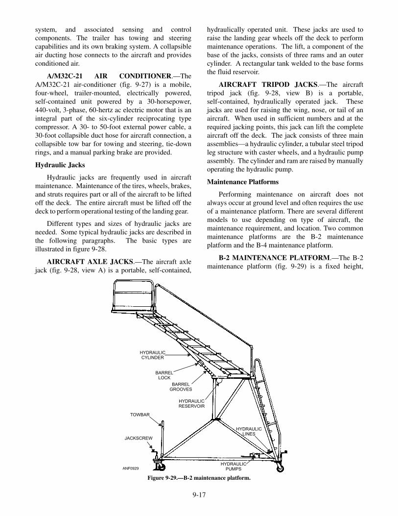
Different types and sizes of hydraulic jacks areneeded. Some typical hydraulic jacks are described inthe following paragraphs. The basic types areillustrated in figure 9-28.
AIRCRAFT AXLE JACKS.—The aircraft axlejack (fig. 9-28, view A) is a portable, self-contained,
hydraulically operated unit. These jacks are used toraise the landing gear wheels off the deck to performmaintenance operations. The lift, a component of thebase of the jacks, consists of three rams and an outercylinder. A rectangular tank welded to the base formsthe fluid reservoir.
AIRCRAFT TRIPOD JACKS.—The aircrafttripod jack (fig. 9-28, view B) is a portable,self-contained, hydraulically operated jack. Thesejacks are used for raising the wing, nose, or tail of anaircraft. When used in sufficient numbers and at therequired jacking points, this jack can lift the completeaircraft off the deck. The jack consists of three mainassemblies—a hydraulic cylinder, a tubular steel tripodleg structure with caster wheels, and a hydraulic pumpassembly. The cylinder and ram are raised by manuallyoperating the hydraulic pump.
Maintenance Platforms
Performing maintenance on aircraft does notalways occur at ground level and often requires the useof a maintenance platform. There are several differentmodels to use depending on type of aircraft, themaintenance requirement, and location. Two commonmaintenance platforms are the B-2 maintenanceplatform and the B-4 maintenance platform.
B-2 MAINTENANCE PLATFORM.—The B-2maintenance platform (fig. 9-29) is a fixed height,
9-17
ANF0929
HYDRAULICCYLINDER
BARRELLOCK
BARRELGROOVES
HYDRAULICRESERVOIR
TOWBAR
JACKSCREW
HYDRAULICPUMPS
HYDRAULICLINES
Figure 9-29.—B-2 maintenance platform.
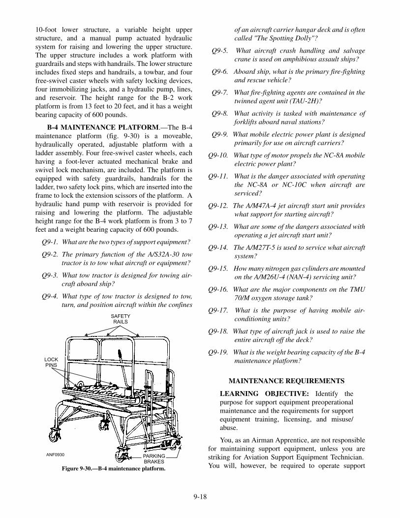
10-foot lower structure, a variable height upperstructure, and a manual pump actuated hydraulicsystem for raising and lowering the upper structure.The upper structure includes a work platform withguardrails and steps with handrails. The lower structureincludes fixed steps and handrails, a towbar, and fourfree-swivel caster wheels with safety locking devices,four immobilizing jacks, and a hydraulic pump, lines,and reservoir. The height range for the B-2 workplatform is from 13 feet to 20 feet, and it has a weightbearing capacity of 600 pounds.
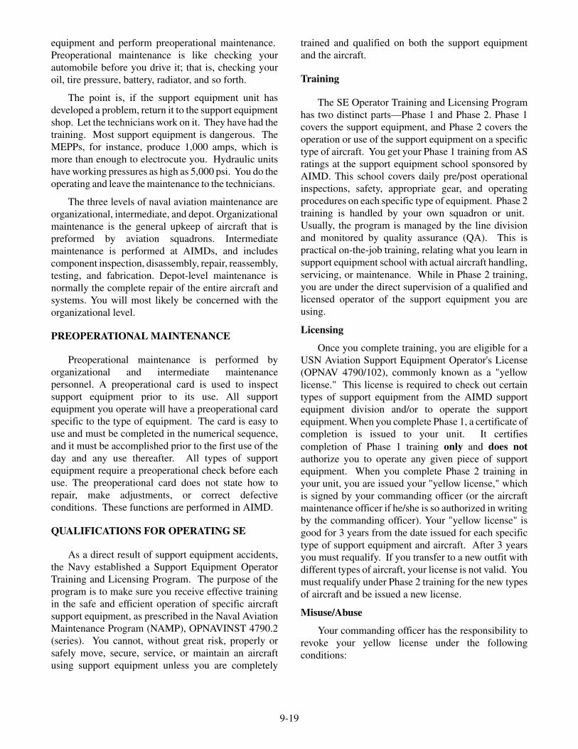
B-4 MAINTENANCE PLATFORM.—The B-4maintenance platform (fig. 9-30) is a moveable,hydraulically operated, adjustable platform with aladder assembly. Four free-swivel caster wheels, eachhaving a foot-lever actuated mechanical brake andswivel lock mechanism, are included. The platform isequipped with safety guardrails, handrails for theladder, two safety lock pins, which are inserted into theframe to lock the extension scissors of the platform. Ahydraulic hand pump with reservoir is provided forraising and lowering the platform. The adjustableheight range for the B-4 work platform is from 3 to 7feet and a weight bearing capacity of 600 pounds.
Q9-1. What are the two types of support equipment?
Q9-2. The primary function of the A/S32A-30 towtractor is to tow what aircraft or equipment?
Q9-3. What tow tractor is designed for towing air-craft aboard ship?
Q9-4. What type of tow tractor is designed to tow,turn, and position aircraft within the confines
of an aircraft carrier hangar deck and is oftencalled "The Spotting Dolly"?
Q9-5. What aircraft crash handling and salvagecrane is used on amphibious assault ships?
Q9-6. Aboard ship, what is the primary fire-fightingand rescue vehicle?
Q9-7. What fire-fighting agents are contained in thetwinned agent unit (TAU-2H)?
Q9-8. What activity is tasked with maintenance offorklifts aboard naval stations?
Q9-9. What mobile electric power plant is designedprimarily for use on aircraft carriers?
Q9-10. What type of motor propels the NC-8A mobileelectric power plant?
Q9-11. What is the danger associated with operatingthe NC-8A or NC-10C when aircraft areserviced?
Q9-12. The A/M47A-4 jet aircraft start unit provideswhat support for starting aircraft?
Q9-13. What are some of the dangers associated withoperating a jet aircraft start unit?
Q9-14. The A/M27T-5 is used to service what aircraftsystem?
Q9-15. How many nitrogen gas cylinders are mountedon the A/M26U-4 (NAN-4) servicing unit?
Q9-16. What are the major components on the TMU70/M oxygen storage tank?
Q9-17. What is the purpose of having mobile air-conditioning units?
Q9-18. What type of aircraft jack is used to raise theentire aircraft off the deck?
Q9-19. What is the weight bearing capacity of the B-4maintenance platform?
MAINTENANCE REQUIREMENTS
LEARNING OBJECTIVE: Identify thepurpose for support equipment preoperationalmaintenance and the requirements for supportequipment training, licensing, and misuse/abuse.
You, as an Airman Apprentice, are not responsiblefor maintaining support equipment, unless you arestriking for Aviation Support Equipment Technician.You will, however, be required to operate support
9-18
SAFETYRAILS
LOCKPINS
PARKINGBRAKES
ANF0930
Figure 9-30.—B-4 maintenance platform.
equipment and perform preoperational maintenance.Preoperational maintenance is like checking yourautomobile before you drive it; that is, checking youroil, tire pressure, battery, radiator, and so forth.
The point is, if the support equipment unit hasdeveloped a problem, return it to the support equipmentshop. Let the technicians work on it. They have had thetraining. Most support equipment is dangerous. TheMEPPs, for instance, produce 1,000 amps, which ismore than enough to electrocute you. Hydraulic unitshave working pressures as high as 5,000 psi. You do theoperating and leave the maintenance to the technicians.
The three levels of naval aviation maintenance areorganizational, intermediate, and depot. Organizationalmaintenance is the general upkeep of aircraft that ispreformed by aviation squadrons. Intermediatemaintenance is performed at AIMDs, and includescomponent inspection, disassembly, repair, reassembly,testing, and fabrication. Depot-level maintenance isnormally the complete repair of the entire aircraft andsystems. You will most likely be concerned with theorganizational level.
PREOPERATIONAL MAINTENANCE
Preoperational maintenance is performed byorganizational and intermediate maintenancepersonnel. A preoperational card is used to inspectsupport equipment prior to its use. All supportequipment you operate will have a preoperational cardspecific to the type of equipment. The card is easy touse and must be completed in the numerical sequence,and it must be accomplished prior to the first use of theday and any use thereafter. All types of supportequipment require a preoperational check before eachuse. The preoperational card does not state how torepair, make adjustments, or correct defectiveconditions. These functions are performed in AIMD.
QUALIFICATIONS FOR OPERATING SE
As a direct result of support equipment accidents,the Navy established a Support Equipment OperatorTraining and Licensing Program. The purpose of theprogram is to make sure you receive effective trainingin the safe and efficient operation of specific aircraftsupport equipment, as prescribed in the Naval AviationMaintenance Program (NAMP), OPNAVINST 4790.2(series). You cannot, without great risk, properly orsafely move, secure, service, or maintain an aircraftusing support equipment unless you are completely
trained and qualified on both the support equipmentand the aircraft.
Training
The SE Operator Training and Licensing Programhas two distinct parts—Phase 1 and Phase 2. Phase 1covers the support equipment, and Phase 2 covers theoperation or use of the support equipment on a specifictype of aircraft. You get your Phase 1 training from ASratings at the support equipment school sponsored byAIMD. This school covers daily pre/post operationalinspections, safety, appropriate gear, and operatingprocedures on each specific type of equipment. Phase 2training is handled by your own squadron or unit.Usually, the program is managed by the line divisionand monitored by quality assurance (QA). This ispractical on-the-job training, relating what you learn insupport equipment school with actual aircraft handling,servicing, or maintenance. While in Phase 2 training,you are under the direct supervision of a qualified andlicensed operator of the support equipment you areusing.
Licensing
Once you complete training, you are eligible for aUSN Aviation Support Equipment Operator's License(OPNAV 4790/102), commonly known as a "yellowlicense." This license is required to check out certaintypes of support equipment from the AIMD supportequipment division and/or to operate the supportequipment. When you complete Phase 1, a certificate ofcompletion is issued to your unit. It certifiescompletion of Phase 1 training only and does notauthorize you to operate any given piece of supportequipment. When you complete Phase 2 training inyour unit, you are issued your "yellow license," whichis signed by your commanding officer (or the aircraftmaintenance officer if he/she is so authorized in writingby the commanding officer). Your "yellow license" isgood for 3 years from the date issued for each specifictype of support equipment and aircraft. After 3 yearsyou must requalify. If you transfer to a new outfit withdifferent types of aircraft, your license is not valid. Youmust requalify under Phase 2 training for the new typesof aircraft and be issued a new license.
Misuse/Abuse
Your commanding officer has the responsibility torevoke your yellow license under the followingconditions:
9-19
� You display unsafe operator habits orbehavioral traits that constitute unsafe orabusive use of support equipment.
� Your State Motor Vehicle Operator's Licensebecomes invalid (applies to self-propelledsupport equipment only).
� You intentionally misuse or abuse supportequipment. Once your yellow license has beenrevoked, you must go through the entire Phase1 and Phase 2 training to requalify for a newlicense.
Local misuse or abuse forms are generallyavailable and may be submitted by anyone witnessingmisuse or abuse regardless of the command to whichthe person is attached. It is common practice aboardstations for the support equipment division to haveroving patrols to observe and report misuse, abuse, anddiscrepancies in all areas and spaces where supportequipment is used. Reports can, and do, result indisciplinary action for improper operation, negligence,or vandalism.
NOTE: For additional information concerningsupport equipment (SE) training, licensing, andmisuse/abuse, refer to Naval Aviation MaintenanceProgram (NAMP), OPNAVINST 4790.2 (series).
Q9-20. What is the purpose of a preoperational cardfor support equipment?
Q9-21. What total number of phases are there in theSupport Equipment Training and LicensingProgram?
Q9-22. What division is normally responsible forphase 2 training of support equipment?
Q9-23. How long is your support equipment "yellowlicense" good for from date of issue?
Q9-24. Who must sign your "yellow license" beforeyou are allowed to operate supportequipment?
Q9-25. Who can submit a misuse/abuse report?
Q9-26. What instruction contains all the informationconcerning support equipment (SE) training,licensing, and misuse/abuse?
SUMMARY
In this chapter you have identified the purpose andfunction of different types of support equipment,handling and servicing equipment, maintenancerequirements, preoperational inspections, and therequirements for support equipment training, licensing,and misuse/abuse.
9-20