us000009354134b220160531 · 2004, pp. 81 and 93, 7th edition, mcgraw-hill publication. parker, p....
TRANSCRIPT

1111111111111111111111111111111111111111111111111111111111111111111111
(12) United States PatentCommo et al.
(54) IN-SITU LOAD SYSTEM FOR CALIBRATINGAND VALIDATING AERODYNAMICPROPERTIES OF SCALED AIRCRAFT INGROUND-BASED AEROSPACE TESTINGAPPLICATIONS
(71) Applicant: U.S.A. as represented by theAdministrator of the NationalAeronautics and SpaceAdministration, Washington, DC (US)
(72) Inventors: Sean A. Commo, Newport News, VA(US); Keith C. Lynn, Newport News,VA (US); Drew Landman, Norfolk, VA(US); Michael J. Acheson, Norfolk, VA(US)
(73) Assignee: THE UNITED STATES OFAMERICA AS REPRESENTED BYTHE ADMINISTRATOR OF THENATIONAL AERONAUTICS ANDSPACE ADMINSTRATION,Washington, DC (US)
(*) Notice: Subject to any disclaimer, the term of thispatent is extended or adjusted under 35U.S.C. 154(b) by 283 days.
(21) Appl. No.: 14/191,898
(22) Filed: Feb. 27, 2014
(65) Prior Publication Data
US 2016/0011068 Al Jan. 14, 2016
Related U.S. Application Data
(60) Provisional application No. 61/774,873, filed on Mar.8, 2013.
(51) Int. Cl.GOIL 25100 (2006.01)
(io) Patent No.: US 9,354,134 B2(45) Date of Patent: May 31, 2016
(52) U.S. Cl.CPC ...................................... GOIL 25100 (2013.01)
(58) Field of Classification SearchCPC .............................. GOIL 25/00; GOIL 25/003USPC .................................................. 73/1.08,1.15See application file for complete search history.
(56) References Cited
U.S. PATENT DOCUMENTS
3,019,643 A 2/1959 Curry5,279,144 A * 1/1994 Levkowitch ........... GOIG23/O1
16/3675,663,497 A 9/1997 Mole6,629,446 B2 * 10/2003 Parker ................ GOIG 23/3728
73/1.15
(Continued)
OTHER PUBLICATIONS
"Recommended Practice: Calibration and Use of internal Strain-Gage Balances with Application to Wind Tunnel Testing," 2003,AIAA R-091-2003, pp. 1-74.
(Continued)
Primary Examiner Peter Macchiarolo
Assistant Examiner Nathaniel Kolb
(74) Attorney, Agent, or Firm Andrea Z. Warmbier
(57) ABSTRACT
An In-Situ Load System for calibrating and validating aero-dynamic properties of scaled aircraft in ground-based aero-space testing applications includes an assembly having upperand lower components that are pivotably interconnected. Atest weight can be connected to the lower component to applya known force to a force balance. The orientation of the forcebalance can be varied, and the measured forces from the forcebalance can be compared to applied loads at various orienta-tions to thereby develop calibration factors.
eA
18 Claims, 7 Drawing Sheets
16
https://ntrs.nasa.gov/search.jsp?R=20160007317 2020-05-16T14:58:07+00:00Z

US 9,354,134 B2Page 2
(56) References Cited
U.S. PATENT DOCUMENTS
9,052,250 B1 6/2015 Parker et al.2002/0088268 Al * 7/2002 Parker ................ GO1G 23/3728
73/1.15
OTHER PUBLICATIONSLynn, K. C. et al., "High-Reynolds Number Active Blowing Semi-Span Force Measurement System Development' 8th InternationalSymposium on Strain-Gauge Balances, May 2012, pp. 1-31.Johnson, T. H. et al., "Calibration Modeling of Nonmonolithic Wind-Tunnel Force Balances," Journal of Aircraft, Nov.-Dec. 2010, pp.1860-1866. vol. 47. No. 6.Montgomery, D. C., "Design and Analysis of Experiments," 2009,pp. 12-13 and pp. 222, 7th ed., John Wiley & Sons, New York.Delroach, R., "Check-Standard Testing Across Multiple TransonicWind Tunnels with the Modern Design of Experiments," AIAA, 28thAerodynamic Measurement Technology, Ground Testing, and FlightTesting Conference, Jun. 2012, pp. 1-25, New Orleans, Louisiana.Lynn, KC. et al., "Wind-Tunnel Balance Characterization forHypersonic Research Applications," Journal of Aircraft, Mar.-Apr.2012, pp. 556-565, vol. 49, No. 2.
Guarino, J., "Calibration and Evaluation of Multi-Component Strain-Gage Balances," NASA Interlaboratory Force Measurements GroupMeeting, Apr. 1964, pp. 1-23, Pasadena, CA.Myers, R. H., "Classical and Modern Regression with Applications,"1990, pp. 41-47 and pp. 112, 2nd ed., Duxberry Press, Belmont, CA.Parker, P. A. et al., "A Single-Vector Force Calibration Method Fea-turing the Modem Design of Experiments," 39th AIAA AerospaceSciences Meeting and Exhibit. Jan. 2001, pp. 1-28.Beer, Ferdinand P. et al., "Vector Mechanics for Engineers: Statics,"2004, pp. 81 and 93, 7th Edition, McGraw-Hill Publication.Parker, P. A. et al., "Advancements in Aircraft Model Force andAttitude Instrumentation by Integrating Statistical Methods," JournalofAircraft, Mar.-Apr. 2007, pp. 436-443, vol. 44, No. 2.Ulbrich, N., "A Universal Tare Load Prediction Algorithm for Strain-Gage Balance Calibration Data Analysis," 47th AIAA/ASME/SAE/ASEE Joint Propulsion Conference and Exhibit, Jul. 31-Aug. 3,2011, pp, 1-19.Myers, Raymond H. et al., "Response Surface Methodology Processand Product Optimization Using Designed Experiments," 2002, pp.303-304, 2nd ed., John Wiley & Sons Publication.
* cited by examiner

U.S. Patent May 31, 2016 Sheet 1 of 7 US 9,354,134 B2
00rn
fn
0LL

U.S. Patent May 31, 2016 Sheet 2 of 7 US 9,354,134 B2
!
N Y j£_~_._— t,Si
t ! CA? 't
3ti
{t i i
l`y f
ON i
yy i ,'r i 1t At "+'a, i ''-_"""`_r~
I!
:i tit ~ ~,.• R'~
t..., j
--------------------------
iA 74 {iZA\
t t\ fa ~p

U.S. Patent May 31, 2016 Sheet 3 of 7 US 9,354,134 B2
I
t-+~' E
Go
f1 t
i ,.ate i
00J
kl ~~/~.
/ 1t n,0
` , d
`
W
7LL
_ _ __________- { 3yf x -- e
A
rn
7
~ ,,,l- v
t00
U.S. Patent
2,Q
~ AM
May 31, 2016 Sheet 4 of 7 US 9,354,134 B2
myµ
,
,
CIO

U.S. Patent May 31, 2016 Sheet 5 of 7 US 9,354,134 B2

U.S. Patent May 31, 2016 Sheet 6 of 7 US 9,354,134 B2
I

U.S. Patent May 31, 2016 Sheet 7 of 7 US 9,354,134 B2
u11 N
{{ 22 t VsE.m- tie.
(sj%) ~1, 4r:
V—
x
Ll- LLLL.
9)F
r~ • Ltl ~ i' i
\f F

US 9,354,134 B2
IN-SITU LOAD SYSTEM FOR CALIBRATINGAND VALIDATING AERODYNAMIC
PROPERTIES OF SCALED AIRCRAFT INGROUND-BASED AEROSPACE TESTING
APPLICATIONS
CROSS-REFERENCE TO RELATEDAPPLICATION
This application claims the benefit of U.S. ProvisionalApplication No. 61/774,873 titled "IN-SITU LOAD SYS-TEM FOR CALIBRATING AND VALIDATING AERODY-NAMIC PROPERTIES OF SCALED AIRCRAFT INGROUND-BASED AEROPACE TESTING APPLICA-TIONS" filed on Mar. 8, 2013, the entire contents of whichare incorporated by reference.
STATEMENT REGARDING FEDERALLYSPONSORED RESEARCH OR DEVELOPMENT
The invention described herein was made in part byemployees of the United States Government and may bemanufactured and used by or for the Government of theUnited States of America for governmental purposes withoutthe payment of any royalties thereon or therefore.
BACKGROUND OF THE INVENTION
Wind-tunnel balances are multi-dimensional force trans-ducers used to obtain high-precision measurements of theaerodynamic loads on an aircraft model during wind-tunneltesting. In many wind tunnels, these aerodynamic measure-ments are made with the measurement device installed insideof the aircraft model, also known as an internal balance.Internal balances are electro-mechanical devices designed toisolate the aerodynamic load components on to a series ofstructural springs, or flexural elements. Strain-gage bridgesare commonly used to measure strain induced in the flexure asa result of deflection. In theory, the flexure deflections and theresulting induced strain are proportional to the imparted load.Six-component internal balances are mechanically designedand instrumented with strain-gage bridges in one of the threefollowing configurations:
Direct-Read (NF, PM, SF, YM, RM, AF)Force (N1, N2, S1, S2, RM, AF)Moment (PML PM2, YMI, YM2, RM, AF)The three types of internal balances measure rolling
moment and axial force directly; however, the remaining fouraerodynamic components are either measured directly, as inthe case of direct-read, or are computed by combining sets ofstrain-gage bridges (i.e. for a force balance, NF=NI+N2 andPM=N1—N2). The type of internal balance impacts both thecalibration and its use.
With reference to FIG. 1, a known internal force balance 20has two attachment points. The non-metric end 22 of thebalance 20 is grounded to the wind-tunnel model supportsystem or model sting 38. The non-metric end 22 of thebalance 20 does not contribute to the sensed force by the forcebalance 20. On the opposite end of the balance 20 is the metricend 24, which attaches to the wind-tunnel aircraft model 25.The metric end 24 is where the aerodynamic loads are trans-ferred into the main body of the balance 20 and the flexurebeams. In addition to the force balance 20, an angle measure-ment system (AMS) may be installed inside of the aircraftmodel 25 for measuring model orientation. Together, theaircraft model 25, model sting, force balance 20, AMS, andother instrumentation comprise a wind-tunnel model system
2(WTMS). Traditionally, these components are considered tobe independent systems with little to no interaction effects.A known approach involves characterizing the measure-
ment systems independently and then the individual compo-5 nents are integrated prior to a test. Under the assumption of no
interaction between the components of the WTMS, thisapproach is sufficient. It is known that interactions can existbetween the components and therefore a methodology tounderstand these effects would be beneficial. A known
10 method for assessing balance performance or WTMS inter-actions is known as check-loading. Check-loading includesapplying a precision load using free-hanging deadweights,hydraulics, or a pneumatic system. Generally speaking,check-loading is currently used prior to a wind-tunnel test to
15 ensure proper installation and integration of the WTMS com-ponents, and to validate that the balance is performing asexpected. The latter requires knowledge of the calibration ofa balance. As the primary source for aerodynamic force andmoment data, balance calibrations play a critical role in the
20 quality of the data collected during a wind-tunnel test; yet, theperformance of a balance cannot be characterized in-situwhile fully integrated in the WTMS. Furthermore, since thereare few recommendations available, the process of check-loading may vary from wind tunnel to wind tunnel. This
25 variability between facilities in combination with limitedresources, such as traceable standards and required hardware,previously prohibited a robust system-level, in-situ charac-terization or validation of the WTMS.
Althoughthe process of check-loading is not standardized,30 many facilities use simple mechanical hardware, similar to
what is used in conventional calibrations, to apply a single- ortwo-component load to the balance or WTMS. More complexloadings are difficult to set-up and execute in a wind tunneland may introduce more uncertainty than they quantify. Axial
35 force check-loads may be difficult to apply because applyingthese loads requires a pulley and cable setup. This type ofsetup increases the odds that additional uncertainties will beintroduced. In aeronautics research, axial force check-loadsprovide valuable information concerning the performance of
40 a balance. However, these loads cannot be applied consis-tently and confidently utilizing conventional methods.TheAIAA paper "Recommended Practice: Calibration and
Use of Internal Strain Gage Balances with Application toWind Tunnel Testing," Tech. Rep. R-091-2003, AIAA, 2003,
45 briefly discusses the role of check-loads. The document sug-gests that check-loads are used to verify the scale factor of thegage bridges between two different environments, such as thecalibration laboratory versus the wind-tunnel test section.Furthermore, it recommends that check-loads should be
50 applied at the facility using the same hardware used duringthe calibration. The document does not address any standardprocedures to be used during 9 balance check-loading, or anystandard metrics that shall be used by the test engineer orresearcher to evaluate the overall performance of the balance
55 in the testing environment.
SUMMARY OF THE INVENTION
One aspect of the present invention is an In-Situ Load60 System (ILS) that addresses the issues noted above. The ILS
includes both physical hardware and a methodology that stan-dardizes the check-loading process. The system-level capa-bilities minimize measurement uncertainties in the data col-lected during a wind-tunnel test. Furthermore, the ILS of the
65 present invention is compact and simple. The ILS may beutilized in connection with internal balances or external semi-span type balances.

US 9,354,134 B2
3One aspect of the present invention is an on-site method of
calibrating a force balance in the presence of a gravitationalfield defining a gravity vector. The method includes providinga force balance defining a force balance coordinate system.The force balance is configured to measure applied roll, pitch,and yaw moments, and axial, side, and normal forces. Themethod includes connecting the force balance to a movablesupport that is capable of rotating the force balance in at leastpitch and roll. An angle measurement system is utilized tomeasure an angular orientation of the force balance relative tothe gravity vector. A pivotable connecting assembly is alsoprovided. The pivotable connecting assembly has an uppermounting structure that is operably connected to the forcebalance such that forces applied to the upper mounting struc-ture are transmitted to the force balance. The upper mountingstructure is pivotably connected to a lower mounting structureby a bearing assembly that permits rotation of the lowermounting structure relative to the upper mounting structure inat least two degrees of freedom such as pitch and roll. A testforce is applied to the lower mounting structure. The test forcemay be applied utilizing a test weight that is operably con-nected to the lower mounting structure to thereby apply aknown test force to the force balance. The test weight may beoperably connected to the lower mounting structure utilizinga test fixture or an aerodynamic model that is to be tested inthe wind tunnel. Force measurements of the force balance arecompared to a test force applied to the force balance at a firstangular orientation of the force balance relative to the gravityvector. The force balance is then rotated to a second angularorientation relative to the gravity vector. Force measurementsof the force balance are compared to a test force applied to theforce balance at the second angular position relative to thegravity vector. The test force provides known loads havingone or more vector components in a coordinate system of theforce balance that can be compared to measured force vectorcomponents from the force balance to develop calibrationfactors that can be utilized during aerodynamic testing toobtain accurate measurements of the aerodynamic forcesaccording to predefined statistical criteria.
Another aspect of the present invention is a method ofcalibrating a force balance in a wind tunnel. The methodincludes connecting a force balance to a movable supportmember in a wind tunnel. A pivoting connecting assemblyhaving at least two rotational degrees of freedom is utilized toapply a test force to the force balance in a known direction.The test force may be applied by connecting a test weight tothe force balance. A first force measurement from the forcebalance is obtained when a known test force is applied to theforce balance with the force balance in a first orientation. Asecond force measurement from the force balance is obtainedwhen a known test force is applied to the force balance whenthe force balance is in a second orientation wherein the forcebalance is rotated relative to the first orientation. The orien-tations of the force balance may be obtained by utilizing anangle measurement system that is mounted to the force bal-ance or a rigid structure that is fixed to the force balance.Calibration factors are generated by comparing the first andsecond force measurements to the known test force to deter-mine differences between the first and second force measure-ments and the known test force whereby the calibration fac-tors can be utilized to measure applied loads duringaerodynamic testing in a wind tunnel.
Another aspect of the present invention is a system forcalibrating a force balance in the presence of a gravitationalfield defining a gravity vector. The system includes a forcebalance configured to measure loads including axial force,normal force, side force, pitching moment, rolling moment,
4and yawing moment in a coordinate system defined by theforce balance. The system also includes a test structure con-nected to the force balance such that loads applied to the teststructure can be measured by the force balance. The system
5 further includes a load bearing assembly including an uppermounting structure secured to the test structure, and a lowermounting structure that is pivotably connected to the uppermounting structure and pivots relative to the upper mountingstructure in at least pitch and roll. The lower mounting struc-
lo ture includes a connector configured to support a test weightto thereby apply a known force to the force balance in thedirection of the gravity vector. The system further includes anangle measurement system that provides gravitation vectorcomponents in the coordinate system of the force balance
15 whereby at least one of the measured loads can be comparedto a known applied load. The test structure may comprise anaerodynamic model, or it may comprise a calibration fixture.
These and other features, advantages, and objects of thepresent invention will be further understood and appreciated
20 by those skilled in the art by reference to the following speci-fication, claims, and appended drawings.
BRIEF DESCRIPTION OF THE DRAWINGS
25 FIG. 1 is a partially schematic isometric view of a knownaerodynamic model and force balance in a wind tunnel;FIG. 2 is a partially schematic isometric view of an In-Situ
Load System (ILS) and aerodynamic model according to oneaspect of the present invention;
30 FIG. 3 is a partially schematic isometric view of an in-SituLoad System (ILS) and test fixture according to one aspect ofthe present invention;
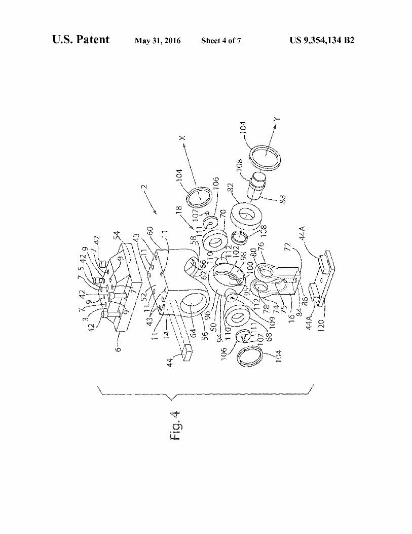
FIG. 4 is an exploded isometric view of an In-Situ LoadSystem (ILS) according to one aspect of the present inven-
35 tion;FIG. 5 is a cross sectional view of the In-Situ Load System
(ILS) of FIG. 4 when assembled;FIG. 6 is an isometric view of an In-Situ Load System (ILS)
showing a wind tunnel coordinate system and a force balance40 coordinate system;
FIG. 7 is a graph showing an applied load space (Fz vs. FX)for the In-Situ Load System (ILS); and
FIG. 8 is a graph showing an applied load space (F. vs. My)for the In-Situ Load System (ILS).
45
DETAILED DESCRIPTION
For purposes of description herein, the terms "upper,""lower," "right," "left," "rear," "front," "vertical," "horizon-
50 tal," and derivatives thereof shall relate to the invention asoriented in FIG. 2. However, it is to be understood that theinvention may assume various alternative orientations andstep sequences, except where expressly specified to the con-trary. It is also to be understood that the specific devices and
55 processes illustrated in the attached drawings, and describedin the following specification, are simply exemplary embodi-ments of the inventive concepts defined in the appendedclaims. Hence, specific dimensions and other physical char-acteristics relating to the embodiments disclosed herein are
6o not to be considered as limiting, unless the claims expresslystate otherwise.
Referring again to FIG. 1, in a typical known wind tunneltest, wind tunnel aerodynamic loads acting on model 25include a normal (lift) force 26, a side force 28, and an axial
65 (drag) force 30. The aerodynamic loads also include a yawmoment 32, a pitch moment 34, and a roll moment 36. Thenonmetric end 22 of force balance 20 may be rigidly inter-

US 9,354,134 B2
5connected to an elongated support structure such as a rod 38that is movably mounted to a base 40. The elongated rod 38may be substantially aligned with the forces 30 acting in anaxial direction. Base 40 may include powered actuators suchthat the elongated rod 38 may be rotated about the x, y, and z 5axes to change the orientation of model 25 relative to thedirection of the air flow ̀ A". The model 25, base 40, and othercomponents may be located inside an elongated passageway12 of the wind tunnel.
With further reference to FIG. 2, an In-Situ Load System io(ILS) 1 of the present invention may include a connectingassembly 2 that is secured to a pad 4 of an aerodynamic model25A. As discussed in more detail below, connecting assembly2 includes a ILS mount 6 having one or more openings 7 orother connectors for connecting the ILS mount 6 to pad 4 of 15aerodynamic model 25A. The aerodynamic model 25A maybe similar to known aerodynamic models 25 (FIG. 1), exceptthat aerodynamic model 25A includes a pad 4 that can be usedto rigidly interconnect model 25A to ILS mount 6 of connect-ing assembly 2. Connecting assembly 2 further includes an 20upper bearing mount 14 that is rigidly connected to ILSmount 6 by threaded fasteners 42. As discussed in more detailbelow in connection with FIG. 4, connecting assembly 2 alsoincludes a lower bearing mount 16 that is pivotably connectedto upper bearing mount 14 by a bearing or connecting asSem- 25bly 18 that provides at least two rotational degrees of freedomto thereby permit the lower bearing mount 16 to rotate relativeto upper bearing mount 14. A test weight 8 can be connectedto the lower bearing mount 16 to thereby generate a test forceFPP acting in the direction of the gravity vector. It will be 30understood that a test force may be generated utilizing apowered actuator such as a hydraulic cylinder or other suit-able device providing a known force in a known direction.Because the lower bearing mount 16 pivots freely relative toupper bearing mount 14, the test force FPP is always parallel 35to the gravitational vector (provided the physical limits ofconnected assembly 2 are not exceeded).A first angle measurement system 44 can be attached to the
upper bearing mount 14, and a second angle measurementsystem 44A can be attached to lower bearing mount 16 uti- 40lizing a plate 120. As discussed in more detail below, the anglemeasurement systems 44 and 44A may comprise known sen-sors that include 3 accelerometers that measure the gravita-tional force such that the orientation of the angle measure-ment systems 44 and 44A relative to a gravity vector defined 45by the earth's gravitational field can be determined. The forcebalance 20, angle measurement systems 44 and 44A, and base40 may be operably connected to a data collection and pro-cessing system 46. It will be understood that the system 46may include a number of computers, controllers, display 50screens, and other devices as required for a particular appli-cation. Also, it will be understood that the base 40 may com-prise a known device of the type utilized in wind tunnels tomovably support aerodynamic models during testing. Theconfiguration of the base 40 may therefore vary depending on 55the particular wind tunnel facility and/or test to be conducted.As discussed above, the ILS 1 may be connected to an
aerodynamic model 25A. Alternatively, ILS 1 may be con-nected to a calibration fixture 48 as shown in FIG. 3. Thecalibration fixture 48 may comprise a known unit of the type 60previously utilized to calibrate force balances 20 in a calibra-tion laboratory. As shown in FIG. 3, the nonmetric end 22 offorce balance 20 may be connected to an elongated supportmember 38A of a base 40A, and calibration fixture 48 may besecured to metric end 24 of force balance 20. The connecting 65assembly 2 is then rigidly connected to the calibration fixture48 utilizing ILS mount 6 and threaded fasteners (not shown)
Tor other suitable connecting arrangement. A first angle mea-surement system 44 may be rigidly mounted to the upperbearing mount 14 of connecting assembly 2, and a secondangle measurement system 44A may be rigidly mounted tolower bearing mount 16. A test weight 8 is secured/mountedto the lower bearing mount 16. Test weight 8 generates anapplied force FPP that is coincident with a gravity vectordefined by the earth's gravitational field. A hydraulic cylinderor other powered actuator may also be utilized to apply a testforce.As discussed in more detail below, the magnitude of the
applied force FPP is known within a high degree of accuracy,and the direction of the applied force FPP is also known. Theangle measurement system 44 provides a precise measure-ment concerning the angular orientation of force balance 20,and second angle measurement system 44A precisely mea-sures the angular orientation of lower bearing mount 16. Itwill be understood that second angle measurement system44A may not be required in every case. For example, it can beassumed that lower bearing mount 16 will always have acertain orientation relative to the gravity vector. Although thisassumption may not be correct due to friction in bearingassembly 18 and other factors, such an assumption may pro-vide sufficient accuracy in some cases.
During calibration of force balance 20, base 40 (or 40A)can be utilized to change the angular orientation of forcebalance 20 by rotating the support member 38 (or 38A) aboutone or more axes. Differences between the measured forcesgenerated by force balance 20 and the applied forces can bedetermined at various angular orientations of force balance20, and these differences can be utilized to generate calibra-tion factors. During aerodynamic testing of aerodynamicmodel 25, 25A, etc., the In-Situ Load System (ILS) 1 isdetached, and the calibration factors can be utilized to providean accurate measurement of forces 26, 28, 30 and moments32, 34, 36 (FIG. 1) resulting from the aerodynamic charac-teristics of the model.
With further reference to FIG. 4, the connecting assembly2 includes an upper mounting structure such as upper bearingmount 14, and a lower mounting structure such as lowerbearing mount 16. When assembled (FIG. 5), the upper andlower bearing mounts 14 and 16, respectively, are rotatablyconnected by bearing assembly 18 to permit rotation of lowerbearing mount 16 relative to upper bearing mount 14 aboutorthogonal axes X and Y.Upper bearing mount 14 includes a flat upper surface 52
that fits closely against a flat lower surface 54 of ILS mount 6when assembled. Threaded fasteners 42 are received inthreaded openings 43 of upper bearing mount 14 to rigidlyinterconnect the ILS mount 6 and upper bearing mount 14. Aplurality of openings 11 in upper bearing mount 14 and cor-responding openings (not shown) in ILS mount 6 receivedowels or pins 13 (FIG. 5) to precisely position upper bearingmount 14 relative to the ILS mount 6. ILS mount 6 includes aplurality of openings 7 and 9 in top surface 3 of ILS mount 6that receive threaded fasteners or the like (not shown) tosecure the ILS mount 6 to pad 4 (FIG. 2) of an aerodynamicmodel 25A, or to a calibration fixture 48 (FIG. 3). A pluralityof openings 9 in ILS mount 6 may receive dowels or otherpins (not shown) to thereby precisely position the ILS mount6 relative to the pad 4 of an aerodynamic model 25A or to acalibration fixture 48. It will be understood that variousmounting hardware and configurations may be utilized torigidly interconnect the connecting assembly 2 to pad 4 of anaerodynamic model 25A or to a calibration fixture 48.The dimensions of the components 6, 14, 16, etc. of ILS 1
are precisely controlled such that the location of the applied

US 9,354,134 B2
VAforce F PP relative to force balance 20 can be determined asthe model 25A or test fixture 48 is rotated. Also, as discussedin more detail below, the weights of the components of ILS 1and the locations of the centers of gravity of the componentsof ILS 1 are also measured/known, such that the input loads toforce balance 20 resulting from these components can betaken into account in determining the total force that isapplied to force balance 20 during calibration.
Referring again to FIG. 4, upper bearing mount 14 includesa base portion 60 and first and second structures or portions 56and 58 that extend downwardly from base portion 60. Thedownwardly extending portions 56 and 58 include openings64 and 66 that receive bearings 68 and 70 when assembled.The central portion 62 of upper bearing mount 14 is hollow toprovide clearance forbearing cross 50 when assembled (FIG.5).Lower bearing mount 16 includes a base portion 72 with
support portions or structures 74 and 76 that extend from thebase portion 72. When assembled, openings 76 and 78 inportions 74 and 76, respectively, receive a pin 83 to therebyrotatably interconnect the lower bearing mount 16 to a bear-ing 82. When assembled, the bearing 82 is disposed in openarea 75 between the portions 74 and 76. A threaded opening86 in lower side surface 84 of lower bearing mount 16 thread-ably receives a threaded rod 88 (FIGS. 2 and 3) of a supportassembly 90 that is utilized to support a test weight 8. The testweights 8 may be in the form of plates, discs, or the like thatare supported on a flat shelf member 92 of support assembly90.
Referring again to FIG. 4, bearing cross 50 comprises aring structure 94 having a curved outer surface 96 and acentral opening 95. Cylindrical surfaces 98 and 100 extendaround opening 95. The cylindrical surface 100 has a some-what smaller diameter than the cylindrical surface 98, and astep or transverse surface 102 extends between the cylindricalsurfaces 98 and 100. When assembled, the bearing 82 abutsthe transverse surface 102 to thereby position the bearing 82at the center of ring structure 94 of bearing cross 50. A retainersuch as a bearing nut 104 may be utilized to retain the bearing82 in the bearing cross 50, and spacers 108 may be utilized toposition the bearing 82 as may be required.
Bearing cross 50 also includes bosses or extensions 110that protrude outwardly in opposite directions from outersurface 96. The extensions 110 include cylindrical outer sur-faces 112 that are received in bearings 68 and 70 when con-necting assembly 2 is assembled. The bearings 68 and 70 maybe positioned and retained by retaining caps 106 and bearingnuts 104. Threaded fasteners 107 may extend through open-ings 111 in retaining caps 106. Threaded fasteners 107engage threaded openings 109 in extensions 110 of bearingcross 50 (see also FIG. 5). The bearings 68, 70, and 82 maycomprise ball bearings having low friction and high toler-ances to ensure that the lower bearing mount 16 can rotaterelative to upper bearing mount 14 without translating (i.e.without "slop") and without generating moments that couldotherwise result if significant rotational resistance werepresent.The accuracy of the data acquired during a wind-tunnel test
is directly related the mechanical and electrical condition of abalance and the quality of a balance calibration. Typically,balance calibrations are performed in a laboratory environ-ment where effects such as temperature, electrical noise, orvibration, are monitored and controlled within acceptablelimits to ensure high-quality calibrations. For strain-gagebal-ances, calibration is the process of estimating the mathemati-cal relationship between an applied load and the electricalresponse of a strain-gage bridge. During a calibration, a load
8is applied to the balance 20 and the electrical response of thebridges are measured. The form of the mathematical model islargely a function of the type of balance and the assumedphysical behavior of balance type. For instance, the math-
s erratical model of a typical six component, single-piece bal-ance is given by
6 6 5 6 6
10 E rFk =flo+E fliFi+E E j8, F, F, -1 Y, /iiiFzk=1 1=1 i=1 j=i+1 1=1
where the rFs are the electrical response of the strain gage, the
15 FS are the applied load in six dimensions, and the (3s are theregression coefficients that are estimated. This form of themathematical model is also known as a second-order Taylor-series expansion in six dimensions. The use of these models inbalance calibrations is known in the art.
20 The mathematical models for characterizing the physicalbehavior of non-single piece balances varies from the modelform given in Eq. (1). While the mathematical models fordifferent balance types varies, the use of an ILS 1 according tothe present invention in these systems does not change. How-
25 ever, consideration is given to the form of the mathematicalmodel and the physical load constraints. Multi-piece bal-ances, which have a rhombus-type force and moment enve-lope, typically exhibit different primary sensitivities based onthe polarity of the applied load. Because of this behavior, the
30 constraints of the balance and the ILS 1 are factored into theload schedule in order to properly characterize the balance 20.When calibrating a balance, a sufficient number of indepen-dent calibration loads should be performed such that all themodel terms can be independently estimated. Each term in the
35 mathematical model represents certain physical properties ofthe force balance. The linear interactions can be attributed tomachining errors, errors in both location and alignment ofstrain gages, and variations in the gage factor for the straingages. The second-order interaction terms are typically asso-
40 ciated with the magnitude of the deflections present in theflexure beams during loading of the balance. Typical balancecalibrations have been conducted with only applied loads asbeing the calibration factors, but it is possible to includeadditional factors, such as pressure and temperature, within
45 the calibration design if it is suspected that they have an effecton the response(s).In general, the purpose of check-loads, or validation loads,
is to ensure adequate characterization of a balance. Check-loads may be used to verify that a given balance measures a
5o known applied load within the quoted accuracy of the bal-ance. The accuracy of a balance may be defined in terms of thestandard deviation of the residual error. A drawback of quot-ing accuracy as a single number is that it lacks the statisticalrigor known about uncertainty intervals in linear regression
55 models.Performing verification and validation reduces risk by col-
lecting information on the system by means of exercising thesystem through its full range of capabilities, objectively ana-lyzing the data, and documenting the results. This reduces
60 operational risks and maximizes system performance, whilebetter estimating the system level uncertainties as related tothe test objectives. The ILS 1 of the present invention pro-vides a tool that permits more accurate system level valida-tions of Wind Tunnel Model Systems. Although the ILS 1 is
65 configured for system level validations in a wind tunnel facil-ity, the ILS 1 could also be used as a calibration device tocalibrate a force balance in a balance calibration lab.
US 9,354,134 B2
9The ILS 1 of the present invention utilizes a single-vector
concept to permit in-situ check-loads at a wind tunnel facility.The single-vector concept involves the transformation of asingle load vector into a reference balance coordinate system,as shown in FIG. 6. The design of the ILS 1 ensures that theload vector coincides with the gravity vector. Based on thebalance coordinate system, the load vector is resolved into thethree forces by:
F'bar F',,Fg (2)
where Fbai is the vector of the three forces defined as [Fx FYFj, F PP is the magnitude of the applied load vector, and g isthe gravity vector describing the orientation of the balanceexpressed as [gx gy g ]'. For a constant FPp, the magnitude ofthe three forces is varied by changing the orientation of thebalance. The components of the gravity vector are expressedin terms of g's and therefore by definition:
gl= e+g~+gyzi. (3)
The moments applied to the force balance 20 are not only afunction of the applied load vector and the orientation of theforce balance 20 but also the distance of the load point from areference point. With reference to FIG. 6, for balances, thisreference point is known as the balance moment center, andwill be referred to herein as BMC 126. The BMC 126 is animaginary point on the balance 20 that is used to define thebalance coordinate frame 125, and is the point by which allforces and moments are referenced.
The distance from BMC 126 is a vector expressed as:
dBMC XBMCYBMCZBMCI (4)
where the sign convention is defined by FIG. 6. The appliedmoments about BMC 126, Mbai, are the vector product of thedistance vector and the balance force vector, or:
Mbar dBMcxF'bar (5)
where Mbai is the vector of the three moments defined as [MxMy Mj and Fbai is given by Eq. 2. The six equations thatdefine the applied forces and moments and the correspondingaerodynamic components are shown in Table 1.
TABLE I
Equations for Calculating Applied Forces and Moments
BalanceComponent Equation
Corresponding AerodynamicComponent
Fx Fx = F PPgx AF = -FxFY FY = F PPgx SF = FYF, F,=F g, NF -FMx Mx = F, (yBMc) - FY (zBMc) RM = MxMY MY = F, (xBmc) - Fx (zBmc) PM = MYM, M, = FY (xBmc) - Fx (yBmc) YM = M,
These equations are used to design the combinations in theload schedule for the ILS 1, and are assumed to be the true,applied loads when comparing to the balance estimated (mea-sured) applied loads.
There are physics-based constraints on the combinations offorces and moments that can be independently applied withthe ILS 1. In general, there are an infinite number of the sixcomponents that can be applied to a force balance with asingle load. However, arbitrary combinations of the threeforces and three moments are not possible due to the require-ment that the resultant force and moment vectors are mutuallyorthogonal. Mathematically, this is expressed as:
F'bai Mba[-O. (6)
10Therefore
(F(M)+(FY)(MY)+(F(M)-O. (7)
Eq. (7) illustrates the three combinations that cannot be5 independently applied: Fx/Mx, F)My, and Fz/Mz. More
explicitly, there exists no possible combinations where onlyFx/Mx, F)My, or Fz/Mz are applied. The ILS 1 has the capa-bility of applying up to five-component loads when mountedat BMC 126 and up to six-component loads when located off
to of BMC 126. Using Eq. (5) at BMC 126, where the x- andy-distances are zero, the moment about the z-axis is:
M =FY(xBMC)-F(YBMC) FY(0)-F (0)=0. (8)
Hence, the sixth component cannot be applied at BMC15 126. Unlike the y-moment arm length, the maximum length
of the x-moment arm is determined by the size of the mount-ing surface. Here, the mounting surface refers to a balancecalibration fixture 48 or wind-tunnel aircraft model (e.g. 125,125A, etc.). For known moderate-capacity force balances 20,
20 the available x-moment arm length is on the order of 2 to 4inches. The available y-moment arm length is a function ofthe geometry of the ILS 1.The ILS 1 can be mounted to a typical balance calibration
fixture 48 as shown in FIG. 3. As discussed above, the con-25 necting assembly 2 includes four main components: the
mount 6, upper bearing mount 14, bearing cross 50, and lowerbearing mount 16. The components may be machined from15-5 PH stainless steel or other suitable material. The upperbearing mount 14 contains a set of two bearings (68, 70) that
30 provides a first degree of freedom for realignment of the loadvector with gravity. The bearing cross 50 contains a secondbearing (82) that provides the second required degree offreedom for ensuring the load vector is collinear with gravity.It is assumed that the point of load application is the intersec-
35 tion of the two bearing axes (i.e. axes X and Y, FIG. 4). Forboth degrees of freedom, there is ±35 degrees of movementavailable for realignment. The ball bearings 68, 70, and 82have a maximum load capacity of 5,000 pounds, which limitsthe magnitude of FPp. The interface between the ILS mount
40 6 and the upper bearing mount 14 provides three discretey-moment arm lengths: —2.25, 0.00, and 2.25 inches. Thelength of the z-moment arm is fixed at 6.75 inches from thetop surface 3 of the ILS mount 6.
Referring to Eq. 2, if the orientation of the force balance 2045 with respect to the gravity vector is known, the applied load
vector can be resolved into the respective aerodynamic com-ponents. FIG. 3 shows an AMS 44 installed on the front 47 ofa calibration fixture 48. The AMS package 44 may comprisethree quartz-type accelerometers that are oriented orthogo-
5o nally in three axes. The AMS voltage output and AMS cali-bration model are used to estimate the gravitational vectorcomponents with respect to the balance coordinate system125.In general, indirect loads that are sensed by a balance may
55 be removed. Examples of indirect (unintended) applied loadsinclude the weight of the balance itself and the weight of thehardware used to apply a load. Thus, the ILS 1 may introducean indirect load. Without removing these auxiliary contribu-tors, the load sensed by the force balance 20 is known as the
60 total load. Tare correction is the mathematical process ofremoving the unintended load from the calculation of thesensed load by the balance. Several methods have been devel-oped for implementing this type of correction. The calculatedload after performing this correction is known as the tare-
65 corrected load. During a wind-tunnel test, the aerodynamicforce and moment data delivered to researchers is typicallytare-corrected. A two-step process may be utilized for per-

US 9,354,134 B211
forming the tare correction when using the ILS 1 of thepresent invention. Since the force balance 20 is installedinside of a calibration fixture 48 or aircraft model 25A, theweight of these components is removed using a tare model.The responses in the strain-gage bridges at force balance 20due to these weights is a function of the orientation of theforce balance 20. A linear mathematical model of this rela-tionship is estimated by:
12According to a specific example, a knownA NTF-113C forcebalance 20 was utilized to test the ILS 1. The NTF-113C is amonolithic, six-component balance that may be used duringfull-span testing at a wind tunnel facility. The full-scale
5 design loads for the NTF0113C are shown in Table 4.
TABLE 4
NTF-113C Balance Design Loads
6 s 10
(9) Design Load
rPra.ek = Yo + Y, Y+S+i=1 1=1 Balance Aerodynamic English Units, Metric United,
Component Component Ibs or in-Ibs N or N-m
where the rFta,,es are the electrical responses of the strain-gagebridges due to the tare load, the gs are the measured compo-nents of the gravity vector that define the orientation of thebalance 20, and the ys are the model coefficients that areestimated. The coefficients in Eq. (9) are estimated from astandard tare sequence shown in Table 2 (below) with thegravity components expressed in units of g's. The design andexecution of the tare sequence is based on response surfacemethodology principles of randomization, replication, anddesired prediction properties of the mathematical model inEq. (9).
TABLE 2
Tare Seauence for the In-Situ Load Svstem in Standard Order
Tare Point No. & gy 91
1 -0.191 -0.694 0.6942 -0.191 0.000 0.9823 -0.191 0.694 0.6944 0.000 -0.707 0.7075 0.000 0.000 1.0006 0.000 0.000 1.0007 0.000 0.000 1.0008 0.000 0.000 1.0009 0.000 0.707 0.70710 0.191 -0.694 0.69411 0.191 0.000 0.98212 0.191 0.694 0.694
However, the weight of the ILS 1 does not have to bemathematically removed, and it may be included in the cal-culation of the desired (intended) applied load. This requiresprecise knowledge of the weight and center of gravity of thecomponents of the ILS 1. Table 3 (below) shows the experi-mentally-determined weights and three dimensional centersof gravity of the ILS mount 6 and ILS subassembly.
TABLE 3
Mass Properties of the In-Situ Load System
Component Weight, Ibs. CG_ in. CGy, in. CG,, in.
ILS Mount 27.64 0.014 -0.009 4.038ILS Subassembly 24.44 0.04 -0.018 7.325
The ILS Subassembly consists of the upper bearing mount14 and the bearing cross 50. It is assumed that the force due tothe lower bearing mount 16 acts through the load point andtherefore the location of the center of gravity is not required.The additional applied force to the balance is the summationof the deadweight load and the weight of the ILS hardware.The applied moments to the balance are calculated by modi-fying the distance vector, damc, to include the center of grav-ity correction, or:
F, NF 6,520 29,00215 Fx AF 400 1,779
My PM 12,800 1,446Mx RM 8,150 920M, YM 6,400 723F, SF 4,000 17,792
20
The ratio of maximum applied load with the ILS 1 to thelargest capacity force component is:
25 Fop - 5,000 (11)
F -77% F, S
, 6,520
For the remaining five components, applying full-scale loads
30 is possible using the ILS 1. The bridge configuration for thetests is a standard force-balance configuration (NF1/NF2,SF1/SF2, RM, andAF). Under this configuration, the strain-gage bridges are placed at two locations axially along thebalance 20. For example, the force in the z-direction, or the
35 normal component of aerodynamic force, is resolved by thesummation of the forward and aft normal bridges.
During testing, the NTF-113C force balance was installedinside of a calibration fixture 48 (FIG. 3). The calibrationfixture 48 provided the necessary interface for mounting the
40 components of ILS system 1. Three sets of holes were drilledinto the calibration fixture 48 for mounting the ILS mount 6 atthree locations axially along the length of the balance 20. Thethree locations established the x-moment arm lengths used inthe calculation of the applied moments. Together, the x-, y-,
45 and z-moment arm lengths were combined to create nine loadpoints, as shown in Table 5. The load space defined by thedistances from balance moment center is shown in FIGS. 7and 8 and is expressed in percent full-scale of a component.For wind-tunnel research, the components of highest interest
50 are typically Fx, Fz, and My. From FIGS. 7 and 8 it is seen thatthe full-scale z-component of force cannot be applied due tothe 5,000 lbs. static load limit of the bearings. However, it ispossible to apply full-scale y-component of force for theentire F. region. Full-scale moments about they-axis are pos-
55 Bible when Fz is at its maximum. The ̀X' pattern seen in FIG.8 is due to the ability of placing the ILS connecting assembly2 at the different locations along the x-axis.
TABLE 560
In-Situ Load System Load Points for NTF-113C
Load Point xBm, 1n yBm , in zBm , in
1 2.25 2.25 8.752 0.00 2.25 8.75
65 3 -2.25 2.25 8.754 2.25 0.00 8.75
dBMC [xBM1+CGJBM1+CGyCGx]' (10)

US 9,354,134 B2
13 14TABLE 5-continued TABLE 6
In-Situ Load System Load Points for NTF-113C Elemental Error Sources for the In-Situ Load System
Load Point xBm, in yBMC, in zBMC, in
5 0.00 0.00 8.756 -2.25 0.00 8.757 2.25 -2.25 8.758 0.00 -2.25 8.759 -2.25 -2.25 8.75
5 Symbol Description
U.UgYUg
U=amt UY.,10 U=Pm
UCC1
x
During the calibration process, estimates of uncertainty in UcclUccl,
load measurements from the force balance are obtained. OF
These estimates of uncertainty include:
errors in setting the applied load due to the hardware used, 15
errors in the mathematical modeling of the balanceresponse, and
random errors.
The current approach employed in estimating balance cali-bration uncertainties utilizes the average residual error fromthe mathematical model, ormean squared error (MSE). Whilecalculating the MSE is straightforward, using the MSE toquote the uncertainty is misleading and often leads to anunderestimate of the true uncertainty. For any given calibra-tion load schedule, it is known that the uncertainty in estimat-ing a load varies throughout the calibration space, whereasthe current approach assumes the uncertainty is constant.Furthermore, the current approach only considers the uncer-tainty from the calibration and excludes the uncertainty that isdue to predicting future observations. Prediction intervals aredeveloped as an alternative to the current approach thataddress the issues previously identified. For a given estimateof a strain-gage bridge response, r^F, at a known load combi-nation, the prediction interval is:
a"2(1+Fo (XX)-'F,) (12)
where t is the value obtained from Student's t-distributionwith a confidence level of 1-a and n-p degrees of freedom,a^2, is the estimate of the MSE, Fo is expanded load combi-nation of size [1 xp], and F is the expanded model matrix ofsize [nxp] based on the reduced calibration models. The inter-vals obtained from Eq. (12) are expressed in terms of thebridge output and therefore the intervals are processedthrough the balance reduction matrix to obtain intervals inunits of forces and moments. The prediction interval providesthe bounds on the estimate for a single applied load.
The ILS is used to apply known total loads including theloads due to the tare weight of the device. In addition toprecisely determining the mass properties, all critical dimen-sions that define the moment arms were evaluated using aMitutoyo model B241 coordinate measuring machine(CMM). A software program was developed that incorpo-rated the precise measurements to calculate the mean loadsincluding tare applied to the test article by the ILS A MonteCarlo simulation was developed to combine all the uncertain-ties including the tolerance of the CMM based measurements,uncertainty in the mass of the applied and tare weights, andthe uncertainty in the accelerometer measurements of thegravity vector. Each source of uncertainty and an estimate ofthe standard deviation are shown in Table 6. Uncertainty inthe forces is primarily a function of the uncertainty in deter-mining the g-vector and relatively constant for the differentconfigurations. Bias in the moments depends on the arms aswell and will vary somewhat more.
StandardDeviation Units
Projection of Gravity vector on x-axis 0.0001 g'sProjection of Gravity vector on y-axis 0.0001 g'sProjection of Gravity vector on z-axis 0.0001 g'sCMM linear Measurements, PID locations 0.0002 inches
Center of Gravity Measurement on x-axis 0.0014 inchesCenter of Gravity Measurement on y-axis 0.0025 inchesCenter of Gravity Measurement on z-axis 0.0011 inchesForce due to Precision Weights 0.01% ES lbs.Force due to ILS Components <5 lbs. 0.00022 lbs.Force due to ILS Components >5 lbs. 0.0022 lbs.
The total absolute uncertainty is a combination of the bal-ance uncertainty and the estimated bias in the applied loadsand depends on the orientation of the components of the ILS
20 system 1 with respect to the force balance 20. An engineeringapproximation for the applied load variance is generatedusing the results from a Monte Carlo simulation and takingthe average of the variance in each component for a given
25 configuration. While this is not a strictly mathematicalapproach, the approximate prediction interval addresses theneed for a practical solution. Combining the two componentsfor the final prediction interval is done by converting theuncertainty in the applied load back to an equivalent voltage
30 using the balance primary sensitivities. The prediction inter-val in Eq. (12) is then adjusted for the bias by adding theadditional variance to the MSE.
Trial loads were applied to the NTF-113C balance in thecalibration fixture block 48 using the ILS. The loads werecomputed using standard NASA Langley Research Center
35 (LaRC) practices and prediction intervals were calculatedbased on the approach described earlier. There were 89 inde-pendent load combinations applied over three different days.Table 7 provides a summary of the test results.
40TABLE 7
Summary of Confirmation Loading Experiment
Number of Total Number Total Number
45 Date Confirmed Points of Points of Loadings
Jul. 11, 2013 165 168 28Jul. 12, 2013 232 240 40Jul. 15, 2013 117 126 21
Total 514 534 8950
Capture Probability 96.3%
TABLES
55 Example In-Situ Load System ConfirmationPoint with Prediction Interval
Applied Estimated 95% PI 95% PILoad, lbs Load, lbs Low, lbs High, lbs
Component or in-lbs or in-lbs or in-lbs or in-lbs60
Fx 143.22 144.18 142.85 145.50F, 3.87 2.81 0.59 5.04F, 2496.70 2495.90 2492.90 2499.00Mx -41.80 -45.95 -65.82 -26.08
M, 4368.60 4368.50 4348.90 4388.10
65 M, -4.64 -3.54 -13.57 6.48
US 9,354,134 B2
15The invention claimed is:1. An on-site method of calibrating a force balance in the
presence of a gravitational field defining a gravity vector, themethod comprising:
providing a force balance defining a force balance coordi-nate system, wherein the force balance is configured tomeasure applied roll, pitch, and yaw moments and axial,side, and normal forces;
connecting the force balance to a movable support that iscapable of rotating the force balance in at least pitch androll;
utilizing an angle measurement system to measure anangular orientation of the force balance relative to thegravity vector;
providing a pivotable connecting assembly having anupper mounting structure that is operably connected tothe force balance such that forces applied to the uppermounting structure are transmitted to the force balancewherein the upper mounting structure is pivotably con-nected to a lower mounting structure by bearings thatpermit rotation of the lower mounting structure relativeto the upper mounting structure in at least pitch and roll;
wherein:the upper mounting structure includes a base portion and
a pair of spaced apart support structures extendingfrom the base portion;
the lower mounting structure includes a base portion anda pair of spaced apart support structures extendingfrom the base portion; and
the pivotable connecting structure further including abearing cross that is rotatably connected to the sup-port structures of the upper mounting structure by firstand second ball bearings, and wherein the bearingcross is rotatably connected to the support structuresof the lower mounting structure by third and fourthball bearings;
operably connecting a test weight to the lower mountingstructure to thereby apply a known test force to the forcebalance;
comparing force measurements of the force balance to atest force applied to the force balance at a first angularorientation of the force balance relative to the gravityvector;
rotating the force balance to a second angular orientationrelative to the gravity vector;
comparing force measurements of the force balance to atest force applied to the force balance at the secondangular position relative to the gravity vector
generating calibration factors by comparing the first andsecond force measurements to the known test force todetermine differences between the first and second forcemeasurements and the known test force whereby thecalibration factors can be utilized to measure appliedloads during aerodynamic testing in a wind tunnel.
2. The method of claim 1, including:providing an aerodynamic model to be tested in a wind
tunnel;connecting the upper mounting structure to the aerody-namic model to the force balance such that test forcesapplied to the pivotable connecting assembly are trans-mitted through the force balance.
3. The method of claim 2, wherein:the movable support is located in a wind tunnel;the test forces are applied to the aerodynamic model in a
wind tunnel.
164. The method of claim 1, including:providing an angle measurement system comprising three
accelerometers that are configured to measure the angu-lar orientation of the angle measurement system relative
5 to the gravity vector.5. The method of claim 4, including:rigidly connecting the angle measurement system to the
upper mounting structure.6. The method of claim 1, wherein:
io the movable support is positioned in a wind tunnel.7. A method of calibrating a force balance in a wind tunnel,
the method comprising:connecting a force balance to a movable support member in
a wind tunnel;15 utilizing a pivoting connecting assembly having at least
two rotational degrees of freedom to connect a testweight to the force balance to thereby apply a known testforce to the force balance wherein the pivoting connect-ing assembly includes upper and lower mounting struc-
20 tures that are pivotably interconnected by a bearing crossand a plurality of bearings to provide at least two degreesof freedom of the lower mounting structure relative tothe upper mounting structure;
obtaining a first force measurement from the force balance25 when a known test force is applied to the force balance
when the force balance is in a first orientation;obtaining a second force measurement from the force bal-
ance when a known test force is applied to the forcebalance when the force balance i s in a second orientation
so wherein the force balance is rotated relative to the firstorientation; and
generating calibration factors by comparing the first andsecond force measurements to the known test force todetermine differences between the first and second force
35 measurements and the known test force whereby thecalibration factors can be utilized to measure appliedloads during aerodynamic testing in a wind tunnel.
8. The method of claim 7, wherein:the method is conducted in a gravitational field defining a
40 unitary gravity vector,the known test force defines a load vector having a magni-
tude and a direction that coincides with a direction of theunitary gravity vector.
9. The method of claim 8, wherein:45 the force balance defines a balance coordinate system at a
balance moment center point;the load vector is applied at a load point that is spaced apartfrom the balance moment center point to define a dis-tance vector extending between the balance moment
50 center point and the load point; andthe test weight generates applied moments about the bal-
ance moment center whereby the applied momentsdefine an applied moment vector that is equal to thevector produce of the distance vector and the load vector.
55 10. The method of claim 9, wherein:the load vector can be expressed in the balance coordinate
system as the product of the magnitude of the load vectorand the gravity vector.
11. The method of claim 10, wherein:60 the wind tunnel defines a generally horizontal primary axis
and generates flow in a first direction that is parallel tothe primary axis;
the balance coordinate system defines a y axis that can bepositioned parallel to the primary axis to measure axial
65 forces on an aerodynamic model in the wind tunnel; andthe y axis is not parallel to the primary axis in at least one
of the first and second orientations such that the load

US 9,354,134 B2
17vector component includes a component that is parallelto the y axis whereby the force balance can be calibratedfor measuring axial forces acting parallel to the y axis.
12. The method of claim 7, including:measuring an orientation of the force balance when the
force balance is in the first and second orientations.13. The method of claim 12, including:providing an angle measuring system that utilizes gravita-
tional forces to measure an orientation of the force bal-ance.
14. The method of claim 7, including:connecting an aerodynamic model to the force balance;connecting the pivoting connecting assembly to the aero-
dynamic model.15. The method of claim 7, including:connecting a calibration fixture to the force balance;connecting the pivoting connecting assembly to the cali-
bration fixture.16. A system for calibrating a force balance in the presence
of a gravitational field defining a gravity vector, the systemcomprising:
a force balance configured to measure loads including axialforce, normal force, side force, pitching moment, rollingmoment and yawing moment in a coordinate systemdefined by the force balance;
18a test structure connected to the force balance such that
loads applied to the test structure can be measured by theforce balance;
a load bearing assembly including an upper mounting5 structure secured to the test structure and a lower mount-
ing structure that is pivotably connected to the uppermounting structure and pivots relative to the uppermounting structure in at least pitch and roll, wherein thelower mounting structure includes a connector config-
10 ured to support a test weight to thereby apply a knownforce to the force balance in the direction of the gravityvector and wherein the pivoting connecting assemblyincludes upper and lower mounting structures that arepivotably interconnected by a bearing cross and a plu-rality of bearings to provide at least two degrees of
is freedom of the lower mounting structure relative to theupper mounting structure; and
an angle measurement system that provides gravitationvector components in the coordinate system of the forcebalance, whereby at least one of the measured loads can
~~ be compared to a known applied load.17. The system of claim 16, wherein:the test structure comprises an aerodynamic model.18. The system of claim 16, wherein:The test structure comprises a calibration fixture.