usa sales offices international stocking … · side view ..... 13 top view ... published in api...
TRANSCRIPT

© 2
012
Loga
n O
il To
ols
1.5M
/081
2 R
2
85-Ton Power Swivel
HeadquartersRemington Square Office Buildin10603 W. Sam Houston Parkway N. Suite 200Houston, Texas 77064-4362 USA832.386.2500 | Fax 281.227.1766
Sales and Manufacturing11006 Lucerne StreetHouston, Texas 77016-1920281.219.6613 | Fax 281.219.6638
Power Swivels11620 Cutten RoadHouston, Texas 77066-3008832.602.2804 | Fax 832.286.4697
INTERNATIONALSTOck INg d ISTRIbuTORSCanadaLogan Oil Tools 9755 45th Avenue NWEdmonton, Alberta T6E 5V8780.433.9957 | Fax 780.468.1979
SingaporeLogan Oil Tools Pte Ltd54 Loyang WaySingapore 50874765.65428422 | Fax 65.65420477
United Arab EmiratesLogan Oil ToolsJebel Ali Free Zone (South)P.O. Box 23724 Dubai, UAE 971.4.813.8000 | Fax 971.4.813.8001
Woodhouse InternationalP.O. Box 23724Dubai, UAE971.4.347.2300 | Fax 971.4.347.4642
United KingdomLogan Oil Tools, U.K. Ltd. Unit C1 Kintore Business ParkKintore, InverurieAberdeenshire AB51 0YQ Scotland+44.1467.631190
uSA SALES OFFIcESCalifornia3155 Pegasus DriveBakersfield, C 93308-6800661.387.1449 | Fax 661.387.1624
Louisiana103 Bluffwood DriveBroussard, LA 70518-3310337.839.2331 | Fax 337.839.2334
118 Common CourtHouma, LA 70360-7982985.868.7333 | Fax 985.868.7007
North Dakota4925 Highway 85 SouthWilliston, ND 58801701.572.0565 | Fax 701.572.0644
Oklahoma424 South Eagle LaneOklahoma City, OK 73128-4225405.782.0625 | Fax 405.782.0760
Pennsylvania244 Grey Fox Drive, Suite 1Montoursville, PA 17754570.546.1066 | Fax 570.546.0388
Texas101 Commerce StreetAlice, TX 78332-2904361.396.0139 | Fax 361.396.0112
11610 Cutten RoadHouston, TX 77066-3008832.602.2134 | Fax 832.286.4117
1305 Energy DriveKilgore, TX 75662-5539903.984.6700 | Fax 903.984.6755
1617 South Viceroy AvenueOdessa, TX 79763-5017432.580.7414 | Fax 432.580.7656
Utah1369 South 1100 EastVernal, UT 84078-8600435.781.2856 | Fax 435.781.2858
1 • Logan 85-Ton Power Swivel
contents
Overview................................................................................2Uses ......................................................................................2Important Safety Information .................................................2Construction ..........................................................................3
Power Swivel Assembly .....................................................3Control Units ......................................................................3Basic Power System ..........................................................4Hydraulic System ...............................................................4Power Unit .........................................................................4
Trailer-Mounted Unit .......................................................4Skid-Mounted Unit ..........................................................4Containerized Unit ..........................................................5
Installation .............................................................................5Rig Up ................................................................................5Pre-Operation Start-up Procedures ...................................5
Electric Controls .............................................................5Air Controls.....................................................................5
Operation ...............................................................................6 General Rules ....................................................................6Air Controls ........................................................................6 Electric Controls .................................................................6
Maintenance ..........................................................................6Power Swivel Maintenance ................................................7 Lubrication .........................................................................7
Breaking-In .....................................................................7Storage ...........................................................................7Replacing the Floating Washpipe Assembly and Packing................................................................7
Power Unit Maintenance ....................................................7Engine ............................................................................7Hydraulic Oil and Filters .................................................7Filters ..............................................................................7Hoses .............................................................................7Power Unit ......................................................................9Power Units With Air Controls ........................................9Power Units With Electric Controls.................................9Power Swivel ..................................................................9
Swivel Disassembly ...............................................................9 Swivel Reassembly .............................................................16Troubleshooting ...................................................................18Specification ......................................................................19Power Swivel Performance Data .........................................20
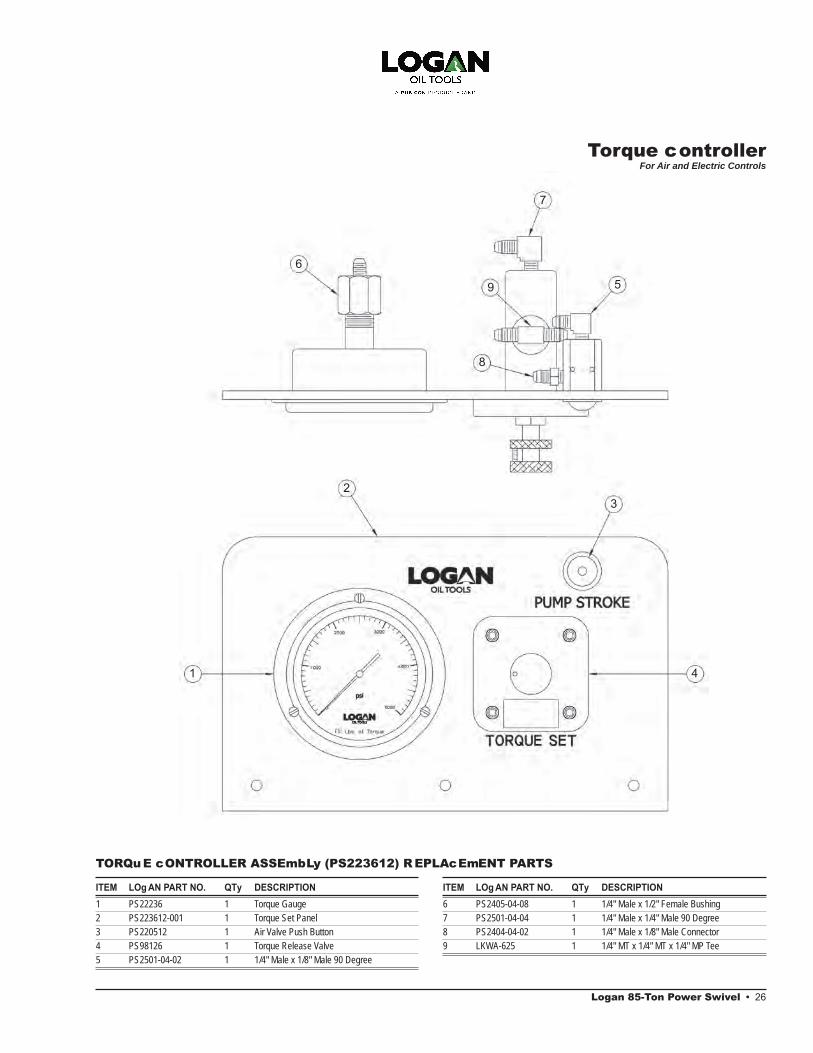
Logan 85-Ton Power Swivel • 26
ITEM LOg AN PART NO. QTy DESCRIPTION 1 PS22236 1 Torque Gauge2 PS223612-001 1 Torque Set Panel3 PS220512 1 Air Valve Push Button4 PS98126 1 Torque Release Valve5 PS2501-04-02 1 1/4" Male x 1/8" Male 90 Degree
TORQuE cONTROLLER ASSEmbLy (PS223612) R EPLAcEmENT PARTS
ITEM LOg AN PART NO. QTy DESCRIPTION 6 PS2405-04-08 1 1/4" Male x 1/2" Female Bushing 7 PS2501-04-04 1 1/4" Male x 1/4" Male 90 Degree8 PS2404-04-02 1 1/4" Male x 1/8" Male Connector9 LKWA-625 1 1/4" MT x 1/4" MT x 1/4" MP Tee
Drawings and SchematicsFloating Washpipe Assembly ................................................8Swivel Head Assembly:
Front View ........................................................................12Side View .........................................................................13Top View ..........................................................................14Section A-A – Through Gear Train) ..................................15 Swivel Head Dimensions .................................................21
Gooseneck Trailer-Mounted Power Unit..............................23Skid-Mounted Power Unit ....................................................24Hydraulic System and Controls ...........................................25Torque Controller (for Air and Electric Controls) ..................26
Assembly and Replacement Parts ListsFloating Washpipe Assembly ................................................8Swivel Head.........................................................................11Torque Reins and Components ...........................................11Power Unit ...........................................................................22Torque Controller .................................................................26
Torque controllerFor Air and Electric Controls
2nd Printing, August 2012. Rev. 2
1
23
4
6
7
59
8

Logan 85-Ton Power Swivel • 2
OVERVIEW
The hydraulic motor-driven, Logan 85-Ton Power Swivel provides smooth,shock-free torque. It is rated to supporttensile pipe loads of 85 tons at zerorpm and 45 tons of dynamic load at 100rpm. The compact, swivel-head designweighs only 1,163 lbs and fits into mostdrilling or workover masts.
The design incorporates a reliable, custom drive train with hardened steel gears. For most applications, the Logan 85-Ton Power Swivel eliminates the useof dangerous spinning chains, tongs,and kelly spinners. The Power Swivelfacilitates drilling with longer drill stringlengths before the rig must be shutdown to add pipe. Stops and start-upsare thereby reduced — improving rigefficiency and reducing wear on thepump, drawworks, and other rig equip-ment.
The Logan 85-Ton Power swivel uses a closed loop hydraulic system with a variable displacement, bi-directional pump, and air or electric remote con-trols. Speed control is continuously variable over the entire operating range. Pressure compensating-type torque control overrides the speed control to maintain maximum torque. The power unit’s torque limits can be set, thereby eliminating the potential danger of twist-offs or swollen boxes in the drill string. An integral rotary swivel bearing, floa -ing washpipe assembly, and gooseneck connection eliminates the need for a separate rotary swivel.
A 2-1/2" bore gooseneck and washpipe assembly allows circulation through the 2" I.D. stem while rotating or in static mode. An access plug allows wireline to be run through the unit.
Features include:• Smooth, shock-free torque reduces
drill string damage• Fits most drilling and work over masts• Allows use of longer drill string lengths• Power unit torque limits can be set• Separate rotary swivel is unnecessary• Choice of diesel engines• Increased environmental safety
features on skids and trailers• Easy to service
Extra cost options, just to name a few, include:• Air- or hydro-start engine• Special hydraulic motor• Lifting frame• Electric or hydraulic loading winch• Hydraulic motor brakes• Control can be operated remotely
or from the power unit• Cold weather package
The complete Logan 85-Ton Power Swivel package includes an elevator-type bail or hook-link adapters; a unitized washpipe packing box assem-bly; a fixed displacement, piston-type,hydraulic motor rated at 5,000 psi; a torque rein assembly; safety cable; and 1-inch quick disconnects. The com-ponents are available either trailer- or skid-mounted with powered hose reels to form a rugged unit. A swivel carrying stand is standard.
CAUTION: Refer to the installation procedure outlined on page 4 before installing the Logan 85-Ton Power Swivel on a rig. Failure to install the Power Swivel properly can result in injury to the operator and/or rig floor personnel. Read Important Safety Information below.
USES
The Logan 85-Ton Power Swivel is ide-ally suited for use in fishing and wor -over operations — such as the internal or external cutting of casing, tubing, or drill pipe; drilling out plugs, packers, or cement; milling operations; or scraping casing — whenever shock-free, con-trolled torque is essential to eliminating the potential danger of twist-offs or damage to cutting tools.
The compact, lightweight swivel-head design also makes it extremely effective for light to medium drilling applications including water wells, pilings for piers and foundations, in addition to oil and gas wells. Suspending the swivel from a boom or crane eliminates a great deal of set-up time or shifts to additional locations.
The Logan 85-Ton Power Swivel is also ideal for coring operations. Any length of core may be taken. Accurate and smooth torque ensures against damage to core tools or strings.
IMPORTANT SAFETY INFORMATION
Before operating the Logan 85-Ton Power Swivel, users are advised of the following important safety precautions and procedures:
1. Verify the strength of the derrickstructure and torque rein guide cableto ensure they are strong enough towithstand the loads imposed by thePower Swivel.
3 • Logan 85-Ton Power Swivel
2. A Logan Safety Cable (provided asstandard equipment on the Logan 85-Ton Power Swivel) should be used fortorque rein and should be utilized atall times. Attach one end of the safetycable to the torque rein and securethe other end to the swivel. In theevent of torque rein assembly failure,the safety cable will prevent theassembly from falling to the rig floo .
3. Carefully check the full range oftravel in the derrick or mast beforebeginning operations. With the guidecable as nearly vertical as possible,ensure that the swivel can movefreely up and down under full torquein either direction. Angles exceeding5% can cause side loads on theswivel.
4. Tubing elevators should not beused with Power Swivel bails.Besides being a potentially danger-
ous practice, the use of an upset elevator reduces the contact between the elevator and bail, and accelerates wear.
5. Inspect elevators and bails for exces- sive wear according to guidelines
published in API RP-8B.
WARNING: Failure to comply with these safety procedures may cause physical injury to the operator and/or rig floor personnel.
CONSTRUCTION
Power Swivel AssemblyThe Logan 85-Ton Power Swivel is powered by a fixed displacement,piston-type, hydraulic motor rated at 5,000 psi. The motor is mounted on the underside of the swivel and is protected by a steel frame.
Two high pressure hydraulic hoses and the motor drain hose exit from the bot-tom of the assembly. The high pressure hydraulic hoses connect to the motor with quick disconnetcs. The motor drain hose is fitted with a self-sealing quickdis-connect coupling.
The one-piece gooseneck is construc-ted of cast steel. A 2-inch I.D. NPT ac-cess plug located in the top allows pas-sage of wireline and small tools through the swivel for downhole operations. The gooseneck and swivel packing are hydrostatically tested and rated at 5,000 psi circulating pressure.
The floating washpipe assembly andpacking are self-aligning. Friction bear-ing surfaces of the washpipe (areas that contact the packing) are hard-surfaced for wear-resistance.
The elevator bail is machined from forged, heat-treated alloy steel for maximum strength. The bail, bail pins, and body are manufactured to API guidelines.
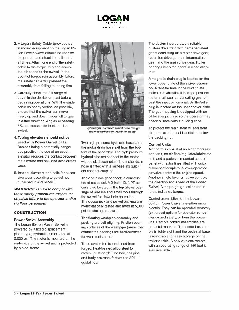
The design incorporates a reliable, custom drive train with hardened steel gears consisting of: a motor drive gear, reduction drive gear, an intermediate gear, and the main drive gear. Roller bearings keep the gears in close align-ment.
A magnetic drain plug is located on the lower cover plate of the swivel assem-bly. A tell-tale hole in the lower plate indicates hydraulic oil leakage past the motor shaft seal or lubricating gear oil past the input pinion shaft. A filler/reliefplug is located on the upper cover plate. The gear housing is equipped with an oil level sight glass so the operator may check oil level with a quick glance.
To protect the main stem oil seal from dirt, an excluder seal is installed below the packing nut.
Control UnitsAir controls consist of an air compressor and tank, an air filter/regulator/lubricatorunit, and a pedestal mounted control panel with extra lines fitted with quickdisconnect couplers. A lever-operated air valve controls the engine speed. Another single-lever air valve controls the direction and speed of the Power Swivel. A torque gauge, calibrated in ft-lbs, indicates torque.
Control assemblies for the Logan 85-Ton Power Swivel are either air orelectric. They can be operated remotely(extra cost option) for operator conve-nience and safety, or from the powerunit. Remote control assemblies arepedestal mounted. The control assem-bly is lightweight and the pedestal baseis removable for easy storage on thetrailer or skid. A new wireless remotewith an operating range of 150 feet isalso available.
Lightweight, compact swivel-head design fits most drilling or workover masts.
The electric control panel consists of a rotary switch for controlling swivel direc-tion and speed, an engine rpm control switch, a digital torque gauge, and an engine kill switch. An emergency kill switch is available for hazardous loca-tions.
Torque limits can be easily and accu-rately set on both air and electric control units. A torque control unit mounted on the fuel tank can be preset to the desired torque limit with the turn of a knob. Torque will be indicated on the control panel in ft-lbs.
Basic Power SystemThe Logan 85-Ton Power Swivel is equipped with a diesel engine to pro-vide power. The engine is sized to provide sufficient horsepower to operate the swivel to full torque and rpm limits. Control systems may be either air or electric.
On units equipped with air control sys-tems, an air compressor, a three-gallon receiver tank, and an air filter-lubricatorare also provided.
Hydraulic SystemThe hydraulic system includes a direct driven, variable displacement hydraulic pump that is mounted directly on the
engine flywheel housing. All piping, valves, fittings, reservoirs, and othercomponents required to complete the system are included. The hydraulic system is designed and rated at 5,000 psi working pressure.
The hydraulic reservoir is designed to dissipate heat and is adequately sized to disperse foam that may be generated during operation. A suction strainer and high pressure filters provide continuousfiltration of the hydraulic fluid. isual registers on the tank return filter andhigh pressure filters indicate whenthese elements need to be replaced.
Hydraulic hoses are reel-mounted on the power unit. They are connected to the power swivel hydraulic motor with quick disconnects.
A swivel carrying rack allows the swivel to be loaded and unloaded without breaking the hose connections.
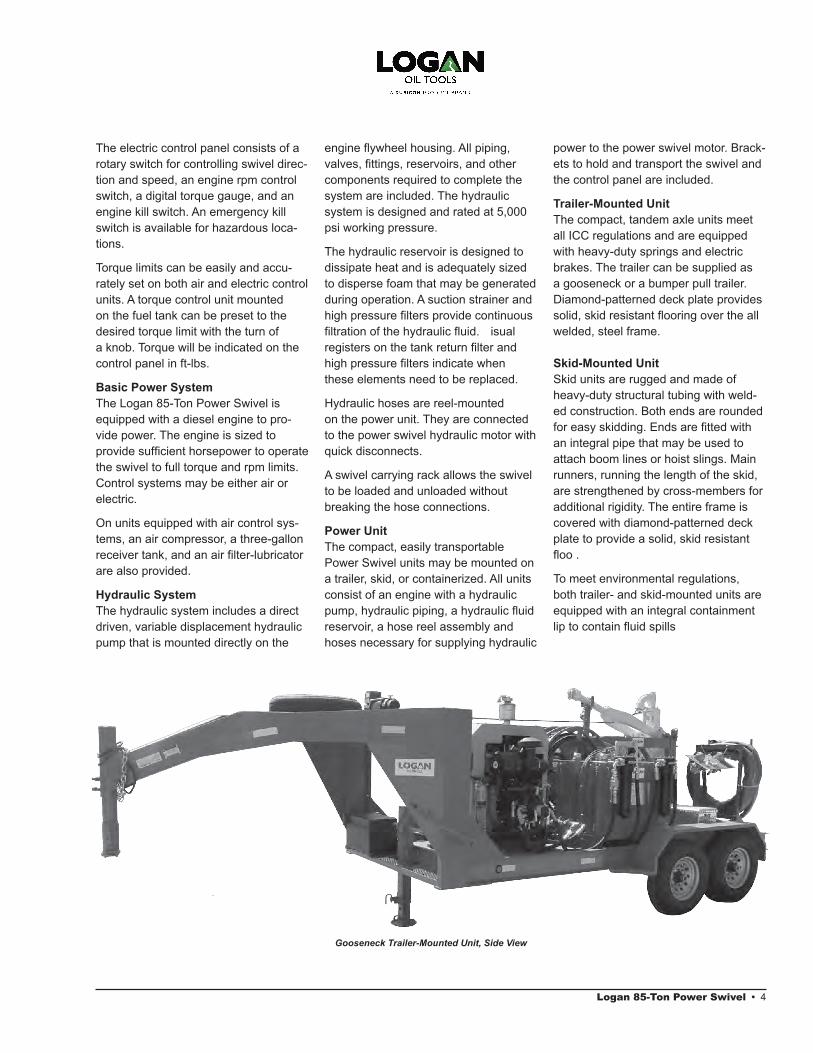
Power UnitThe compact, easily transportable Power Swivel units may be mounted on a trailer, skid, or containerized. All units consist of an engine with a hydraulic pump, hydraulic piping, a hydraulic fluidreservoir, a hose reel assembly and hoses necessary for supplying hydraulic
power to the power swivel motor. Brack-ets to hold and transport the swivel and the control panel are included.
Trailer-Mounted UnitThe compact, tandem axle units meet all ICC regulations and are equipped with heavy-duty springs and electric brakes. The trailer can be supplied as a gooseneck or a bumper pull trailer. Diamond-patterned deck plate provides solid, skid resistant flooring over the allwelded, steel frame.
Skid-Mounted UnitSkid units are rugged and made of heavy-duty structural tubing with weld-ed construction. Both ends are rounded for easy skidding. Ends are fitted withan integral pipe that may be used to attach boom lines or hoist slings. Main runners, running the length of the skid, are strengthened by cross-members for additional rigidity. The entire frame is covered with diamond-patterned deck plate to provide a solid, skid resistant floo .
To meet environmental regulations, both trailer- and skid-mounted units are equipped with an integral containment lip to contain fluid spills
Gooseneck Trailer-Mounted Unit, Side View
Logan 85-Ton Power Swivel • 4

5 • Logan 85-Ton Power Swivel
Containerized UnitContainerized units are built into a 20-foot ocean container. The containers are equipped with two bi-fold doors on one side, and double doors in the rear, to allow complete access. A louvered vent, which has an adjustable cover that can be sealed off for storage or trans-port, is installed on the front. The floor is diamond tread steel plate.
INSTALLATION
Rig UpCheck all components to ensure that all accessory items (especially the port-able control panel) and spare parts are packed, and that all equipment is in serviceable condition. If time per-mits, the operator should run the power swivel for a short time to check control indicators, filte , and response of con-trols, etc. before leaving for the job site. Be sure to have an ample supply of fuel and that the hydraulic reservoir is full.
Upon arriving at the job site, the power unit should be placed in a level position a safe distance from the well head and other hazards. All corners of skid units should be supported. On trailer units, wheel chocks should be set in front and in back of the wheels and the jack low-ered to level the trailer bed.
Using a catline or derrick line, lift the swivel unit from the rack. Suspend the swivel over the well head from the drilling hook or elevators. Be sure the elevator is the correct size for the ele-vator bail. Carefully inspect the elevator for excessive wear (refer to API RP-8B for guidelines).
Remove the control cable or air control hoses and the pressure gauge hose from their storage hangers on the skid or trailer. Connect them to their respec-tive connections on the power unit and control panel.
Pre-Operation Start-up ProceduresElectric Controls1. Move the "ENGINE" throttle switch
to “IDLE” position.
2. Move the swivel "SPEED" knob tothe "STOP" position (left).
3. Turn on the control power at thePower Unit.
4. Start the engine and allow the unitto warm up.
5. Turn the "ENGINE" switch to the"RUN" position.
6. Set the torque limit using the controlpanel located on top of the fuel tank,stroke the pump "FWD" and adjustthe torque set knob to the desiredmaximum torque.
7. Set the "DIRECTION" switch to thedesired rotation — "FWD" or "RVS"(the center position is neutral).
8. Slowly increase the "SPEED" knobuntil the swivel reaches the desiredspeed or the maximum torque limit.
9. Check the high pressure filterslocated on the fuel tank. If the indi-
cator is in the red, change the filters
10. Check the return filte . If the indica- tor gauge is in the red, replace the
filte .
Air Controls1. Move the engine throttle control
lever to idle position (decrease).
2. Move the swivel control lever toneutral position (center).
3. Start the engine and allow the unitto warm up.
4. Check the condition of the returnfilte . The filter indicator is locatedon top of the hydraulic reservoir.Replace the filter if the gauge is inthe red.
5. Check the air filter/regulatorlubricator unit. Air pressure shouldread 100 psi or more. Lubricatorshould be full of oil. Filter should befree of water. If water is present,
Power Swivel Electric Control Panel
open the drain valve on the bottom of air reservoir to drain the water. Close the drain valve.
6. Set the torque control to the desiredmaximum torque. The torque con-
trol system is mounted on top of the fuel tank. The adjustment knob and torque indicator gauge are cali-
brated in ft-lbs. Turn the adjustment knob until the desired maximum torque is indicated on the gauge.
7. Move the swivel control handle tothe “forward” position.
8. Increase engine throttle until thedesired engine rpm is attained andthe engine runs smoothly.
9. Check the high pressure filterindicator.
The Logan 85-Ton Power Swivel is now ready for operation.
OPERATION
General RulesLogan Oil Tools recommends the follow-ing rules be observed when operating the Power Swivel. These operational rules apply to all power swivel units, whether they are equipped with air or electric controls.
1. The pump displacement controlshould always be used to changethe speed of the swivel. Setting theengine at the rated rpm will prolongengine and pump life, burn less oil,and result in increased fuel economy.
2. When changing the direction ofrotation, move the Swivel Control tothe center or neutral position, waitfor the swivel to come to a completestop, and then proceed with thechange in rotation.
3. Filters should be checked on a dailybasis.
4. The hydraulic fluid level should bechecked daily. If the level is belowthe sight gauge, add hydraulic fluid
5. Do not permit the hydraulic oiltemperature to exceed 190°F forextended periods.
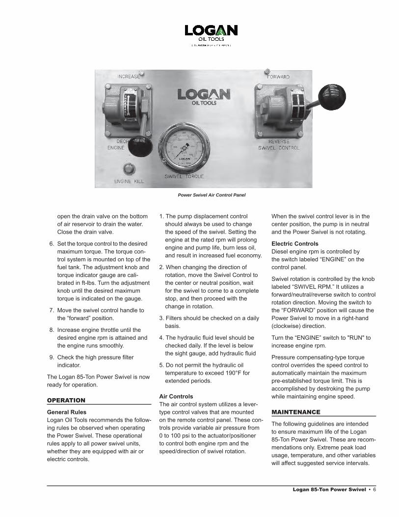
Air ControlsThe air control system utilizes a lever-type control valves that are mounted on the remote control panel. These con-trols provide variable air pressure from 0 to 100 psi to the actuator/positioner to control both engine rpm and the speed/direction of swivel rotation.
Power Swivel Air Control Panel
When the swivel control lever is in the center position, the pump is in neutral and the Power Swivel is not rotating.
Electric ControlsDiesel engine rpm is controlled by the switch labeled “ENGINE” on the control panel.
Swivel rotation is controlled by the knob labeled “SWIVEL RPM.” It utilizes a forward/neutral/reverse switch to control rotation direction. Moving the switch to the “FORWARD” position will cause the Power Swivel to move in a right-hand (clockwise) direction.
Turn the “ENGINE” switch to "RUN" to increase engine rpm.
Pressure compensating-type torque control overrides the speed control to automatically maintain the maximum pre-established torque limit. This is accomplished by destroking the pump while maintaining engine speed.
MAINTENANCE
The following guidelines are intended to ensure maximum life of the Logan 85-Ton Power Swivel. These are recom-mendations only. Extreme peak loadusage, temperature, and other variableswill affect suggested service intervals.
Logan 85-Ton Power Swivel • 6

7 • Logan 85-Ton Power Swivel
Power Swivel MaintenanceLubrication1. Check the gear lubricating oil prior
to service. The oil level should bemaintained at the oil level plug levelat all times. If necessary, bring oil tothe proper operating level by adding85w 140 gear lubricant. Some lubri-
cating oil may leak out when the oil level plug near the top cover plate is removed. If oil does not leak out, gear lubricating oil of proper type and grade should be added to the correct operating level.
2. Gear lubricating oil should bechanged after the first 100 hours ofinitial operation. Check the magneticdrain plug for metal filings whechanging the gear lubricating oil.
NOTE: Oil capacity of the Logan 85-Ton Power Swivel is two (2) gallons.
3. After the initial break-in period (first100 hours of operation), the gearlubricating oil should be changedafter each 1,000 hours of operationthereafter, or if the unit has been outof service for an extended period.Always check the magnetic drainplug for metal filings when changingthe gear lubricating oil.
4. The elevator bail, stem, and saversubs should undergo magnetic par-
ticle inspection every five (5) years
Breaking-InDuring initial break-in, or after a long period of idleness, run the Power Swivel with a reduced load at slower speed until it reaches normal operating tem-perature ranging between 120 – 200°F. A somewhat higher operating tempera-ture is permissible in very hot climates, provided that it increases gradually.
StorageIf the Logan 85-Ton Power Swivel must be stored, it should be completely filledwith gear lubricating oil to prevent oxi-dation. Thread protectors or lift plugs should be installed on stems or saver
subs to prevent damage to the threads. Grease or dope the threads before installing the thread protectors or lift plugs.
Open gear housings, ports, and re-moved motors should be covered with clean drop cloths to prevent dirt and trash from entering internal mecha-nisms. Before shipping parts for service, all openings should be sealed and parts wrapped in clean, heavy kraft paper.
Replacing the Floating Washpipe Assembly and PackingThe entire Floating Washpipe Assembly, including the upper and lower packing nuts, can be removed from the swivel without removing the gooseneck or bonnet.
Remove the four retainers and retain-ing screws from the lower packing nut. Loosen the lower packing nut by turning it in a clockwise direction until it turns freely. Secure the upper stem to keep it from rotating while loosening and removing the lower packing nut. Use the same procedure to loosen and remove the upper packing nut from the gooseneck.
Remove the washpipe and packing as-semblies. Press the washpipe out of the lower packing nut and slide the upper nut off. Remove the three upper packing locking pins and press the up-per packing off the washpipe. Replace the washpipe if it shows any signs of wear (i.e., scoring or surface abrasion).
The average life expectancy of the packing is 200 – 250 hours. Remove the old packing from the packing nuts. Thoroughly clean the inside of both nuts. Using the drawing on page 8 as a reference, install the new packing. Assemble the packing and floatingwashpipe assembly in reverse of as-sembly procedure. Tighten the packing nuts securely, locking them in place with the retaining screws and retainers.
Power Unit MaintenanceThe Power Unit includes the engine, piping, filters, reservoi , hoses, hose reels, cables, electrical components, and gauges.
EnginePlease refer to the specific engine manufacturer’s maintenance instructions included with your documentation.
Hydraulic Oil and FiltersThe hydraulic fluid reservoir (Logan Part No. PS06206) should be maintained at the proper level at all times. The oil level should be visible in the sight gauge when cold.
FiltersThe return filter located at the top of thereservoir should be replaced when the pointer indicates that it needs cleaning. The indicator registers when the engine is running.
The high pressure filter in the pre -sure line should be serviced when the condition indicator displays red. Green indicates that the filter is in satisfactorycondition. The filter indicator operateswhen the swivel is rotating to the right.
HosesLubricate the hose reel swivel joints with automotive chassis grease monthly.
Inspect the torque control mechanism every six months and coat all moving parts with automotive chassis grease.
Avoid contaminating the hydraulic fluidand hydraulic system, including the hoses and couplings, with dust, water, or other foreign matter. Introduction of foreign materials into the system will damage the machinery.
Torque gauge hose end connec-tions should be kept clean at all times through the use of dust covers or by wrapping them with a clean cloth when not in use. Open, loose ends, especially those that have been dropped on the ground, should be thoroughly cleaned inside and out, and flushed prior to use
15
16
17
18
11
19
87
20
5
1
2
6
5
4
7
3
98
10
11
12
1413
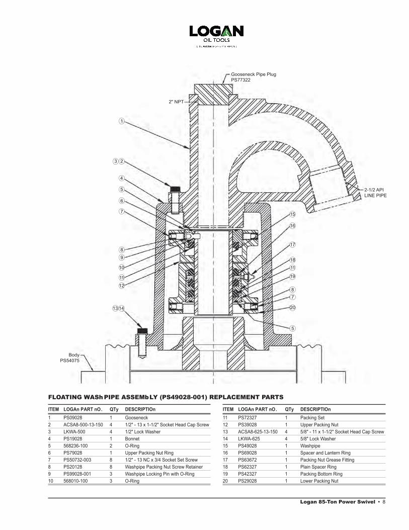
ITEM LOGAn PART nO. QTy DESCRIPTIOn
1 PS09028 1 Gooseneck2 ACSA8-500-13-150 4 1/2" - 13 x 1-1/2" Socket Head Cap Screw3 LKWA-500 4 1/2" Lock Washer4 PS19028 1 Bonnet5 568236-100 2 O-Ring 6 PS79028 1 Upper Packing Nut Ring7 PS50732-003 8 1/2" - 13 NC x 3/4 Socket Set Screw8 PS20128 8 Washpipe Packing Nut Screw Retainer9 PS99028-001 3 Washpipe Locking Pin with O-Ring10 568010-100 3 O-Ring
FLOATING WAShPIPE ASSEMbLY (PS49028-001) REPLACEMENT PARTS
ITEM LOGAn PART nO. QTy DESCRIPTIOn
11 PS72327 1 Packing Set 12 PS39028 1 Upper Packing Nut13 ACSA8-625-13-150 4 5/8" - 11 x 1-1/2" Socket Head Cap Screw14 LKWA-625 4 5/8" Lock Washer 15 PS49028 1 Washpipe16 PS69028 1 Spacer and Lantern Ring17 PS63672 1 Packing Nut Grease Fitting 18 PS62327 1 Plain Spacer Ring19 PS42327 1 Packing Bottom Ring20 PS29028 1 Lower Packing Nut
Logan 85-Ton Power Swivel • 8
BodyPS54075
2" NPT
Gooseneck Pipe Plug PS77322
2-1/2 API LINE PIPE
9 • Logan 85-Ton Power Swivel
Extend the life of the hoses by never allowing them to become twisted or kinked, or unnecessarily stretched. Do not allow any sharp or heavy objects to drop or lay on the hoses. Doing so may cut or crush them.
Machinery and hoses should not be allowed to remain outdoors when not in use.
In cold climates, it is particularly impor-tant to keep the hydraulic system free of moisture caused by condensation or water contaminated hydraulic fluid. Any moisture in the system may freeze and cause severe damage, especially to the pump and valves.
Power UnitInspect trailer-mounted units prior to use to ensure that it is safe and road-worthy. Pay particular attention when inspecting the following items:
1. Trailer hitch and safety chain2. Brakes and tires3. Tail and brake lights, and turn signals4. Reserve fuel supply5. Trailer tongue jack and supports
Thoroughly clean the power unit when the job has been completed. Replenish the engine fuel and hydraulic oil sup-plies. Make any necessary repairs at this time. Hoses should be reeled after cleaning and the hose ends covered.
Power Units with Air ControlsExpel water condensate from the tank daily by opening the drain valve on the bottom of the air receiver. Pressurize the tank before opening the valve.
Visually inspect the filter/lubricator valvetwice a day. Drain any water that has collected in the filter bowl and maintainthe lubricating oil at the proper operat-ing level with SAE 10W motor oil.
Always keep the pump stroke cylinder rod, rod bearing, and clevis coated with chassis grease.
Power Units with Electric ControlsThe electrical cable should be coiled and stored on the cable bracket when not in use. Cover the open end with the provided dust cap. Avoid kinking or placing undue tension on the cable. Do not allow equipment to run over the cable.
Open the relay cabinet at least once a year (more often in humid climates) for cleaning. All exposed terminals and metal parts should be cleaned, dried, and sprayed with silicone or varnish.
Power SwivelPower swivels should not be started or operated in freezing weather until the hydraulic system has been properly prepared for cold weather service by:
1. Charge the hydraulic system withhydraulic oil rated for cold weather.
2. Prepare the engine according to themanufacturer's recommendations.
3. Ensure the hydraulic system ismoisture-free.
SWIVEL DISASSEMbLY
Care should be taken to ensure that no foreign material enters the interior machinery of the swivel. All disassembly and major repairs should be conducted in a clean, well-equipped shop.
1. Remove all hydraulic hoses from theswivel. Hose ends should be coveredto help prevent foreign matter fromentering the interior.
NOTE: When not in use, all hydrau-lic hoses should be reeled up to prevent kinking and other damage. Damaged hoses may cause blockage or other interference that the unit may not function properly.
2. Place the swivel on a suitable rack(similar to the bracket on the skid ortrailer) that supports the swivel on itsbail pins.
3. Remove the hydraulic motor guard.
4. Place an open container under themagnetic drain plug and removethe plug. Check the drain plug anddrained gear oil for metal filings andother foreign matter.
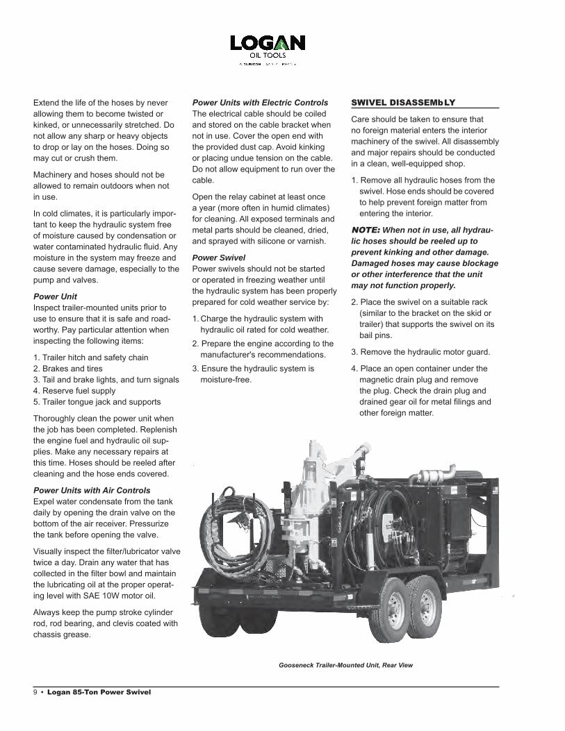
Gooseneck Trailer-Mounted Unit, Rear View
5. Remove the four retaining screwsand their retainers from the lowerpacking nut. Secure the lower stemof the swivel to keep the upper stemfrom turning while loosening the lowerpacking nut. Turn the lower packingnut in a clockwise direction until itturns freely. Back the lower packingnut completely off the upper stem.
Repeat the above procedure toremove the upper packing nut andback it completely off the gooseneck.Remove the floating washpipe andpacking assembly.
6. Press the washpipe out of the lowerpacking nut and slide the upper nutoff. Remove the three upper packinglocking pins and press the upperpacking off the washpipe. Replacethe washpipe if it shows any signs ofwear (scoring or surface abrasion).
7. Remove the packing assembly partsfrom inside both nuts. (The lowerpacking assembly consists of anO-ring, packing bottom ring, plainspacer ring, spacer and lantern ring,and three packing seals. The upperpacking assembly consists of anO-ring, upper packing nut ring, andone packing seal.) When replacingthe packing, it is important that bothpacking nuts are clean and free of allold packing residue. Make sure bothpacking nuts are clean and free offoreign matter.
8. Remove and set aside the gooseneck and bonnet.
9. Turn the swivel upside down. Re- move the hydraulic motor and set it
aside.
NOTE: Do not disassemble the hy-draulic motor. If trouble with the mo-tor is known or suspected, carefully plug the ports and return the motor to Logan Oil Tools for inspection and repair.
10. Remove the lower bearing retainerscrews. Set the retainer aside andremove the gasket.
11. Remove the seal retainer snap ringfrom the bearing retainer and thetwo lower oil seals.
12. Turn the swivel upright and removethe upper seal protector from the topof the stem.
13. Remove the cap screws from thetop cover plate. A rubber mallet maybe used to break the gasket sealif necessary. Lift off the top coverplate.
14. Remove the upper gear cover shimand gasket. A putty knife or otherthin tool may be used for prying andcleaning.
15. Remove the oil seal from the uppercover plate. Using an inside bearingpuller, pull the outer race of thestem upper bearing from the topcover plate. This will free the stemfor removal.
16. The inner race of the stem’s upperand lower bearings and seal wearring at the bottom of the stem maybe removed with a bearing puller.The final reduction gear is removedby first removing the six ring groovepins and then forcing the gear off themain stem.
17. Remove the screws from the lowergear cover plate. Tap the cover plategently with a rubber mallet to breakthe seal if necessary. Scrape offremaining residue with a putty knife.
18. Remove the first reduction pinionbearing spacer and the first reduction pinion lower bearing from theswivel body.
19. Lift out the final reduction pinion,main thrust bearing, second reduc-
tion pinion, and first reduction pinion. The gears may require rotation to facilitate removal.
20. Remove the remaining roller bear- ings, second reduction lower bear- ing with its retainer ring, and first
reduction pinion upper bearing. As with all bearings, exercise caution when handling to guard against possible damage.
NOTE: Each part should be thor-oughly cleaned (with steam or a high pressure washer for metal parts, or with a good grade solvent) as it is removed. Check parts for repair or replacement as they are cleaned. Dry all cleaned parts with compressed air or a clean, soft cloth. Coat all clean, dry parts with a thin coat of lubricat-ing oil. Never leave parts exposed overnight without a coating of pro-tective oil.
21. Remove the bail only when abso- lutely necessary. Lay the bail and
swivel body down so the holes at the bottom of the bail pockets in the
body can be reached. Set a 10- inch-long dowel rod with a diameter slightly smaller than the bail pocket holes against the pin. Strike the dowel with a hammer. Once the grooved pin has been removed, insert a rod in the pull pin hole. Use a rubber mallet to loosen the bail pin by tapping it in alternate direc-
tions. Pour penetrating oil around the pin to aid the loosening process.
While pulling on the pin, repeat the loosening process until the pin is removed. Lift out the bail.
NOTE: In the event hydraulic mo-tors, hoses, or similar items are to be stored or shipped for repair, all ports and openings should be carefully sealed to prevent foreign matter from entering interior parts.
Logan 85-Ton Power Swivel • 10
11 • Logan 85-Ton Power Swivel
ITEM PART nO. QTy. DESCRIPTIOn
1 PS09028 1 Gooseneck2 ACSA8-500-13-150 14 1/2" - 13 x 1-1/2" Long Socket Head Cap Screw3 LKWA-500 18 1/2" Lockwasher 4 PS19028 1 Bonnet 5 568236 2 O-Ring 6 PS79028 1 Upper Packing Nut Ring 7 PS50732-003 8 1/2" - 13 NC x 3/4" Long Socket Set Screw
with Brass Point8 PS20128 8 Washpipe Packing Nut Screw Retainer 9 PS99028 3 Washpipe Locking Pin with 568010 O-Ring 10 568010 3 O-Ring 11 PS72327 1 Set Packing 12 PS39028 1 Upper Packing Nut 13 ACSA8-625-13-150 8 5/8" - 11 x 1-1/2" Long Socket Head Cap Screw14 LKWA-625 23 5/8" Lockwasher 15 PS49028 1 Washpipe 16 PS69028 1 Spacer and Lantern Ring 17 PS63672 1 Packing Nut Grease Fitting 18 PS62327 1 Plain Spacer Ring 19 PS42327 1 Packing Bottom Ring 20 PS29028 1 Lower Packing Nut 21 HCSA8-625-13-150 9 5/8" - 11 x 1-1/2" Long Hex Head Cap Screw 22 PS44322 4 Dowel Pin 23 AHSS-625-11-625 4 5/8" - 11 x 5/8" Long Allen Head Set Screw24 PS77122 1 Filler Plug Relief Fitting 25 PS98352 1 Oil Filler Plug 26 PS72602 1 Magnetic Drain Plug 27 PS72516 1 7/8" - 14 NPT x 3/4" Adapter 28 PS26274 1 3/4" x 90, 150# Street Ell 29 PS86753 1 3/4" Close Nipple 30 PS79052-001 1 3/4" Wing Nut Quick Disconnect31 PS90152-002 1 3/4" Metal Dust Cap32 PS90152-003 1 3/4" Metal Dust Plug 33 PS55164 1 Lower Bearing Retainer Gasket34 HCSA8-625-11-175 6 5/8" - 11 x 1-3/4" Long Hex Head Cap Screw 35 PS50602 1 Saver Sub 36 HCSA8-500-13-150 4 1/2" - 13 x 1-1/2" Long Hex Head Cap Screw 38 PS53506 2 1" Swivel Joint 39 PS55115-003 1 Shackle40 PS55115-002 1 Torque Rein Assembly (Long)41 PS697702 1 Torque Rein Eye 42 PS21415 1 Torque Rein Pull Pin43 PS91875 1 Upper Gear Cover Shim 44 PS91826-003 1 Hydraulic Motor45 PS65895 2 1" - 4" Bolt Elbow Flange46 568219-200 2 Flange O-Ring47 ACSA8-375-13-275 8 3/8" - 16 x 2-3/4" Long Socket Head Cap Screw
ITEM PART nO. QTy. DESCRIPTIOn
48 LKWA-375 8 3/8" Lockwasher 49 PS77322 1 Gooseneck Pipe Plug 50 PS20213-001 1 Elevator Bail (Cast)51 PS28444 1 Seal Protector52 PS34813-001 2 Bolt and Nut for Bail Pin53 PS65115 2 Bail Pin 54 PS12965 1 Final Reduction Gear55 PS64702 6 Ring Gear Groove Pin 56 PS98402 1 Main Thrust Bearing57 PS04685 1 Lower Stem Bearing Spacer 58 PS70602 1 Lower Stem Bearing 59 PS54075 1 Body 60 PS14685 1 Lower Stem Bearing Retainer 61 PS22602 2 Lower Oil Seal 62 PS16303 1 Seal Retainer Snap Ring 63 PS51602 1 Lower Seal Wear Ring 64 PS18444-001 1 Stem 65 PS64165 1 Second Reduction Pinion 66 PS05775 1 Second Reduction Gear Key 67 PS15165 1 First Reduction Pinion Upper Bearing 68 PS37965 1 First Reduction Pinion Upper Gear 69 PS05165 1 First Reduction Pinion Lower Bearing 70 PS44685 1 First Reduction Pinion Bearing Spacer 71 PS12685 1 Lower Gear Cover Gasket 72 PS25165 1 First Reduction Pinion Oil Seal 73 PS62516 1 Hydraulic Motor Adapter 74 PS08327 1 Retainer Ring 75 PS97327 1 Motor Adapter Sleeve 76 PS45165 1 Retainer Ring 77 PS85152 1 Second Reduction Shaft Lower Bearing 78 PS65165 2 Reduction Gear Key79 PS95675 1 Lower Gear Cover Plate 80 PS27965 1 First Reduction Gear 81 PS84165 3 Roller Bearing 82 PS55935 1 Oil Seal Grease Fitting 83 PS90137 1 Oil Level Indicator Plug 84 PS88402 1 Upper Stem Bearing 85 PS02685 1 Upper Oil Seal86 PS12165 1 Second Reduction Gear87 PS53775 1 Upper Gear Cover Plate88 PS03165 1 Final Reduction Pinion89 PS95516-001 1 Motor Guard90 PSWB3 3 Hose Safety Cable91 G14085-BULK HD-85W-140 Gear Lube, 2.5 Gal92 PS65152 1 1" Quick Disconnect Coupler93 PS01152 1 1" Quick Disconnect Nipple
PS71107-001 Hydraulic Motor Shaft Seal Kit
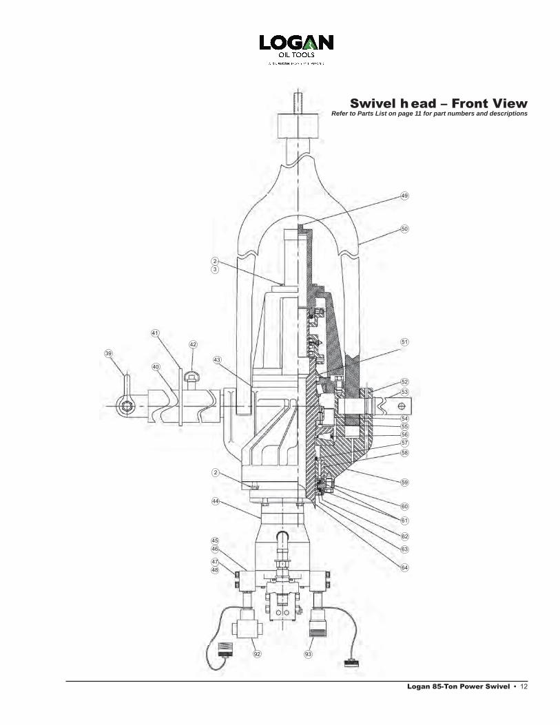
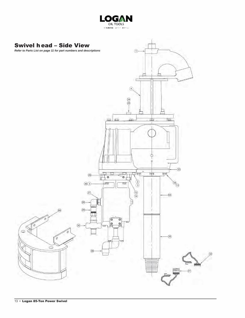
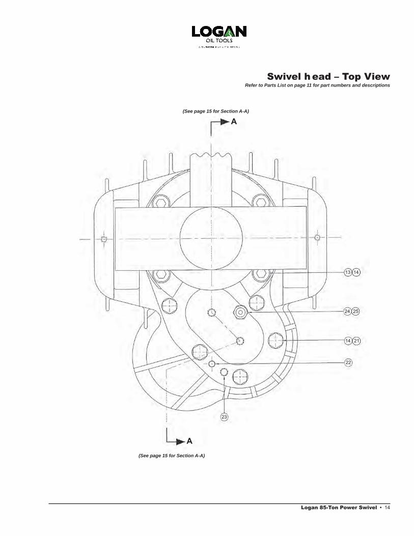
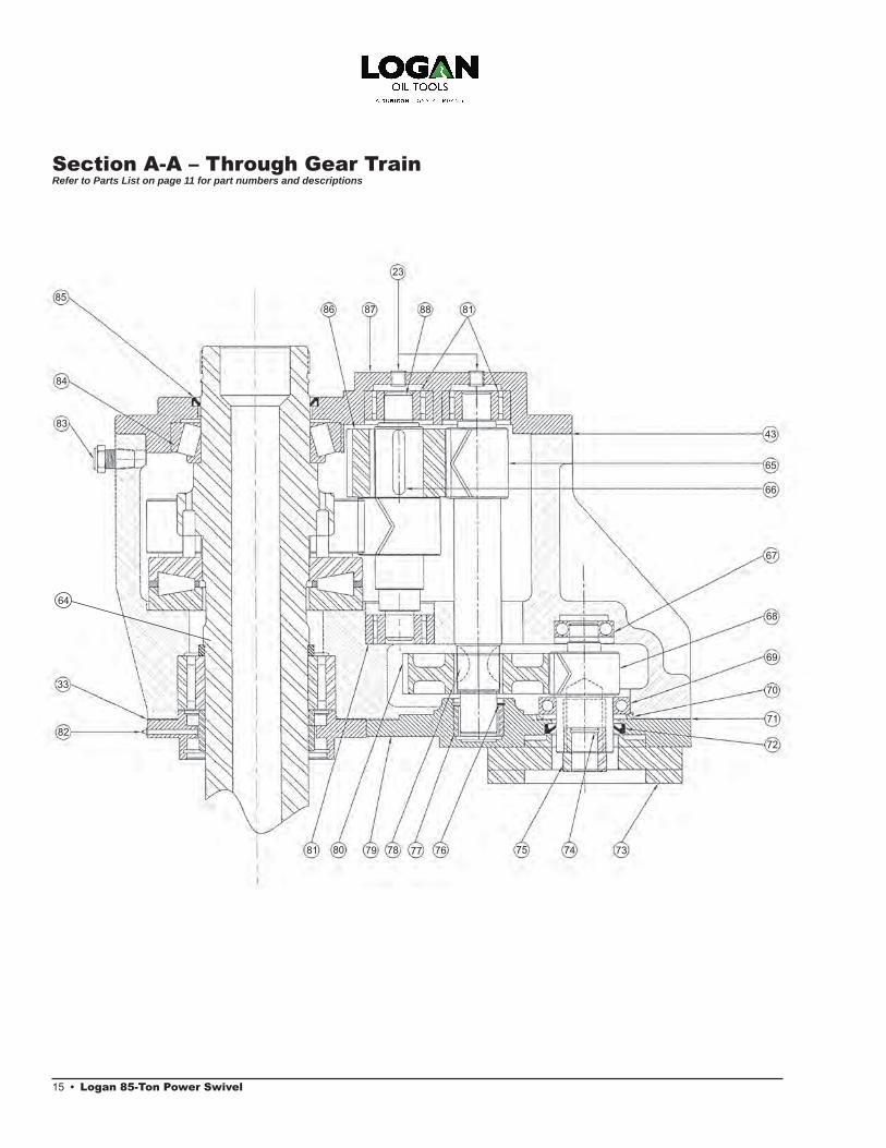
Swivel head Parts ListItem numbers refer to drawing callouts on pages 12 – 15
TORQUE REINS AND COMPONENTS
PART nO. DESCRIPTIOn LEnGTH/STROKE
PS55115-002 PS85 Long Torque Rein (standard with head or unit) Retracted 31.25"/Extended 48.5" LongPS55115-001 PS85 Short Torque Rein Retracted 20"/Extended 26.5" LongPS55115-006 PS85 Extra Short Torque Rein Retracted 12"/Extended 19" Long PS55116-001 PS85 Torque Rein Roller Assembly (includes insert to minimize movement to Torque Rein)
Logan 85-Ton Power Swivel • 12
43
42
41
40
39
2
44
45
47
46
48
49
50
51
52
53
57
58
545556
23
59
64
63
62
60
61
92 93
Swivel head – Front ViewRefer to Parts List on page 11 for part numbers and descriptions
13 • Logan 85-Ton Power Swivel
Swivel head – Side ViewRefer to Parts List on page 11 for part numbers and descriptions
28
29
30
3238
31
3
13
236
14
3
33
1334
64
35
2524
26
1
4
27
89
13 14
24 25
14 21
22
23
A
A
Swivel head – Top ViewRefer to Parts List on page 11 for part numbers and descriptions
(See page 15 for Section A-A)
(See page 15 for Section A-A)
Logan 85-Ton Power Swivel • 14
15 • Logan 85-Ton Power Swivel
Section A-A – Through Gear TrainRefer to Parts List on page 11 for part numbers and descriptions
86 87 88 81
23
43
65
66
67
68
69
70
71
72
85
84
83
33
82
81 80 79 78 77 76 75 74 73
64

SWIVEL REASSEMbLY
Care should be taken to ensure that no foreign material enters the interior machinery of the swivel. All major repairs and reassembly should be con-ducted in a clean, well-equipped shop.
In the event hydraulic motors, hoses, or similar items are to be stored or shipped for repair, all ports and openings should be carefully sealed to prevent foreign matter from entering.
NOTE: All parts should be thorough-ly cleaned, dried, oiled, and in good operating condition. Never reuse the gear lubricating oil drained from the swivel. Always use new, fresh oil of the recommended type and grade. O-rings should never be reused. It isalso recommended that all oil sealsbe replaced.
1. Place the swivel on a suitable rack(similar to the bracket on the skidor trailer) that supports the swivelon its bail pins.
2. Install component parts on thestem:
a. Press final reduction gear backon the stem and install groovepin.
b. Press on upper stem bearing.
c. Install main thrust bearing.
d. Install stem lower bearing spacer.
e. Press on lower stem bearinginner race.
f. Press on lower seal wear ring.
3. Install component parts onto shafts:
a. Install key and second reductiongear onto final reduction pinion
b. Press roller bearings onto eachend of final reduction pinion
c. Press roller bearing on upper endof second reduction pinion.
d. Press first reduction pinion lowerbearing onto first reductionpinion.
4. With the stem lower bearing inplace, set the main stem throughthe stem lower bearing into positionin the body.
5. Check the top face of the body,making sure that the surface isclean and free of burrs. Place agasket on the face of the body.
6. Place a set of three shims (oneeach in thicknesses of .005", .007",and .020") on the body face.
7. With the upper cover plate upright,press the upper oil seal into posi-
tion. Press the outer race of the stem upper bearing into the top cover plate.
8. Position the upper cover plate overthe stem and into place on thebody. Insert cap screws with lockwashers into the upper plate andtighten.
9. Place a small hydraulic jack underthe lower end of the stem and amicrometer against the top of thestem to detect and measure anyvertical movement (end-play). Applylift to the stem with the jack andnote any movement shown on themicrometer.
10. Remove the jack, micrometer, andthe top cover plate. Remove theshims and replace them with acombination of shims that will allowa sufficient total amount of end-playbetween .004" and .005".
NOTE: Do not tighten the cover plate without sufficient shims or over-tighten the upper plate cover screws. Doing so will cause the bear-ings to bind.
11. Press the second reduction pinionlower bearing into the lower coverplate. Set the retainer ring into posi-
tion above the bearing and press the first pinion upper bearing into place in the body.
12. Set the first reduction pinion, firsreduction gear, and first reductionpinion bearing spacer into place inthe swivel body.
13. Remove the top cover plate andset the final and second reductionpinion into place. Rotate the shaftsin order to mesh the gears. Rein-
stall the top cover plate and tighten the screws.
14. Turn the swivel upside down. Checkthe bottom surface of the body forburrs and flatness. Lay the lowercover gasket on the face. Positionthe lower cover plate on the bodyand insert the cap screws with lockwashers. Tighten the screws.
15. Place the two lower stem oil sealsinto position on the stem’s lowerbearing retainer. Set the seal retain-
er snap ring on the bearing retainer. When properly assembled, the lips of the oil seals should point upward.
Exercise caution when assembling the oil seals over the wear ring, being careful not to tear or turn back the lips of the oil seals or cause other damage to the seals. Dam aged seals will cause leakage. Set the lower bearing retainer over the stem and in place on the body. Insert the six lower bearing retainer cap screws with lock washers. Tighten the screws.
16. Insert the first reduction pinion oilseal. Place the hydraulic motorwith the hydraulic motor adapterattached into position. Insert theeight cap screws with lock washers.Tighten the screws. Attach thehydraulic motor guard.
17. Turn the body upright.
18. Grease the upper oil seal and placethe upper seal protector in positionon the stem. Make sure the sealprotector is right-side up with the lipagainst the upper cover plate.
Logan 85-Ton Power Swivel • 16

17 • Logan 85-Ton Power Swivel
19. Assemble the bonnet to the uppercover plate and bolt the gooseneckto the bonnet. Insert the gooseneckpipe plug and tighten.
20. Coat the packing elements (O-rings,upper packing nut ring, packing,spacer and lantern ring, plainspacer ring, and packing bottomring) generously with Logan packinglubricant and install them into theirrespective packing nuts. Reassem-
ble the floating washpipe assembly and packing in reverse of the dis-
assembly procedure outlined on page 7. Reinstall the packing nuts, retainers, and retainer screws, tight-
ening and locking the packing nuts securely.
Securely tighten the packing nuts and lock into place with their re spective retainers and retainer screws.
21. Lay the unit flat on a workbenchand insert the bail into the bailpockets of the body. Align the bailpins with the lock pin holes in thebody. Secure the bail by drivingthe bails pins into place with a rub-
ber mallet. As the lock pins come into alignment, drop a drift punch through them, driving lightly to laterally align them.
22. Drop the bail pin grooves into placeand snug-up with a hammer. Hangup the swivel by the bail and sup-
port the underside of the swivel. Using a medium weight (2-1/2 lbs) sledge hammer, drive the pins in straight through until the heads are flush with the top of the bail pock ets.
23. Reattach all piping to the hydraulicmotors before reattaching the motorguard.
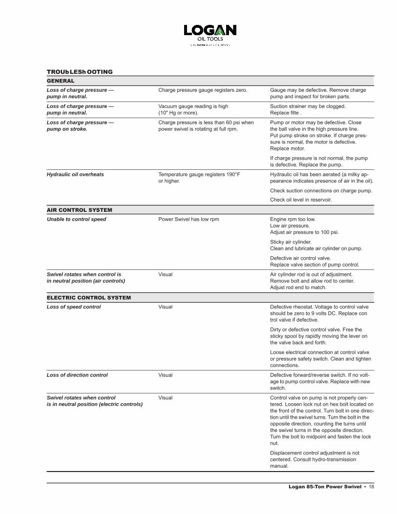
GENERAL
Loss of charge pressure — Charge pressure gauge registers zero. Gauge may be defective. Remove charge pump in neutral. pump and inspect for broken parts.
Loss of charge pressure — Vacuum gauge reading is high Suction strainer may be clogged. pump in neutral. (10" Hg or more). Replace filte .
Loss of charge pressure — Charge pressure is less than 60 psi when Pump or motor may be defective. Closepump on stroke. power swivel is rotating at full rpm. the ball valve in the high pressure line.
Put pump stroke on stroke. If charge pres- sure is normal, the motor is defective.
Replace motor.
If charge pressure is not normal, the pump is defective. Replace the pump.
Hydraulic oil overheats Temperature gauge registers 190°F Hydraulic oil has been aerated (a milky ap- or higher. pearance indicates presence of air in the oil).
Check suction connections on charge pump.
Check oil level in reservoir.
AIR CONTROL SYSTEM
Unable to control speed Power Swivel has low rpm Engine rpm too low. Low air pressure. Adjust air pressure to 100 psi.
Sticky air cylinder. Clean and lubricate air cylinder on pump.
Defective air control valve. Replace valve section of pump control.
Swivel rotates when control is Visual Air cylinder rod is out of adjustment. in neutral position (air controls) Remove bolt and allow rod to center.
Adjust rod end to match.
ELECTRIC CONTROL SYSTEM
Loss of speed control Visual Defective rheostat. Voltage to control valve should be zero to 9 volts DC. Replace con trol valve if defective.
Dirty or defective control valve. Free the sticky spool by rapidly moving the lever on the valve back and forth.
Loose electrical connection at control valve or pressure safety switch. Clean and tighten connections.
Loss of direction control Visual Defective forward/reverse switch. If no volt- age to pump control valve. Replace with new
switch.
Swivel rotates when control Visual Control valve on pump is not properly cen- is in neutral position (electric controls) tered. Loosen lock nut on hex bolt located on
the front of the control. Turn bolt in one direc- tion until the swivel turns. Turn the bolt in the
opposite direction, counting the turns until the swivel turns in the opposite direction. Turn the bolt to midpoint and fasten the lock nut.
Displacement control adjustment is not centered. Consult hydro-transmission manual.
TROUbLEShOOTING
Logan 85-Ton Power Swivel • 18
19 • Logan 85-Ton Power Swivel
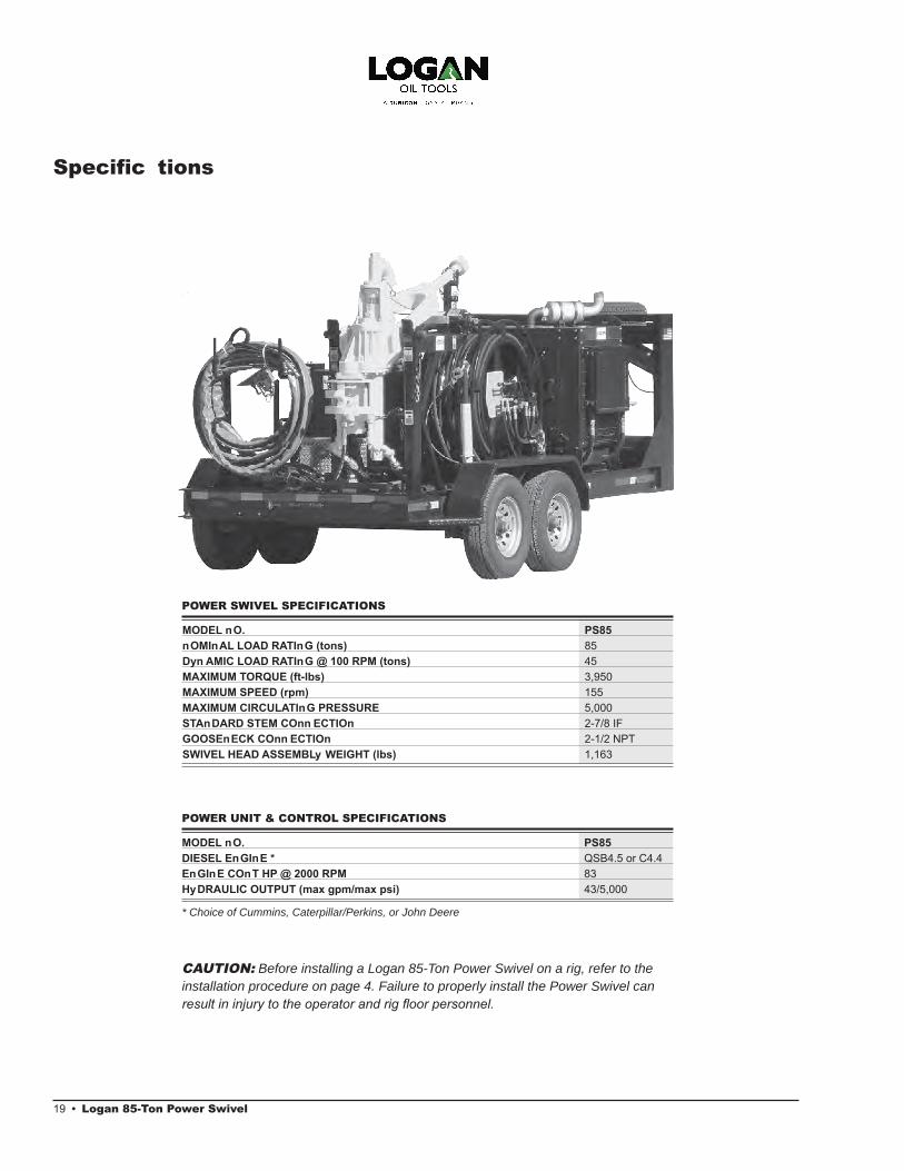
Specific tions
POWER UNIT & CONTROL SPECIFICATIONS
MODEL nO. PS85 DIESEL EnGInE * QSB4.5 or C4.4EnGInE COnT HP @ 2000 RPM 83HyDRAULIC OUTPUT (max gpm/max psi) 43/5,000
* Choice of Cummins, Caterpillar/Perkins, or John Deere
MODEL nO. PS85nOMInAL LOAD RATInG (tons) 85Dyn AMIC LOAD RATInG @ 100 RPM (tons) 45MAXIMUM TORQUE (ft-lbs) 3,950MAXIMUM SPEED (rpm) 155MAXIMUM CIRCULATInG PRESSURE 5,000STAnDARD STEM COnn ECTIOn 2-7/8 IFGOOSEnECK COnn ECTIOn 2-1/2 NPTSWIVEL HEAD ASSEMBLy WEIGHT (lbs) 1,163
POWER SWIVEL SPECIFICATIONS
CAUTION: Before installing a Logan 85-Ton Power Swivel on a rig, refer to the installation procedure on page 4. Failure to properly install the Power Swivel can result in injury to the operator and rig floor personnel.

87 hp Output Cummins 4BT
020
4060
80100
120140
160180
200
Swivel Stem rpm
4,000
3,000
2,000
3,500
2,500
1,500
Out
put
Torq
ue f
t/lb
s
Drill Pipe rpm
Allo
wab
le L
ift
Load
bs
180,000
160,000
140,000
120,000
100,000
80,000
60,0000 10 20 30 40 50 60 70 80 90 100 110 120 130 140 150 160 170 180
Performance Data
Logan 85-Ton Power Swivel • 20
21 • Logan 85-Ton Power Swivel
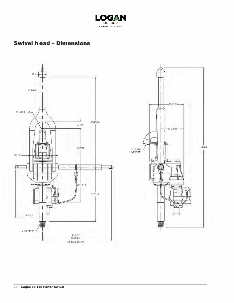
Swivel head – Dimensions
2" NPT PLUG
4-1/32
23-5/32
20-15/16
18-1/2
16-5/32
2-7/8 API IF
32-7/16
53-15/16
Ø 5
Ø 2-7/8
41-7/32 CLOSED
58-17/32 OPEN
20-17/32
13-23/32
19-1/22-1/2 API
LINE PIPE

LOGAn PART nO. QTy DESCRIPTIOn
HyDRAULIC PUMPPS311412-001 1 Hydraulic Pump for Air Controls, Closed LoopPS311412-002 1 Hydraulic Pump for Electric ControlsPS02196 1 Pump Stroke PositionerPS02196-002 1 Pump Stroke Positioner Repair KitPS339412 1 Pump Stroke Positioner BracketPS73426 1 1/4" Check ValvePS255002 1 Pump Motor Adapter PS99376-002 1 Auxiliary Pump (Hose Reel Hydraulic Winch)PS529412 1 Air Shuttle Valve (Pump Stroke)HyDRAULIC RESERVOIRPS89046-001 1 40 gal Hydraulic Tank ReservoirConsisting of:PS780412 1 Hydraulic Suction StrainerPS754T08N 1 Hydraulic Suction 2" Ball ValvePS099612 1 Hydraulic Return Filter AssemblyPS099612-001 1 Hydraulic Return Filter Element OnlyPS02311 1 Filler Breather CapPS30795-002 1 Oil Level Gauge with TemperaturePS89046 1 Hydraulic Reservoir OnlyPS233612 1 Relief Back Pressure OrificPS529412 Air Shuttle ValveFUEL TAnKPS96892-001 1 60 gal Fuel Tank AssemblyConsisting of:PS96892 1 Fuel Tank OnlyPS96892-2 2 Fuel Sight Tube PS94626 1 1-1/4" High Pressure Ball Valve PS61648 2 High Pressure Filter AssembliesPS02311 1 Filler Breather CapPS811412 1 Fuel Suction TubePS811412-A 1 Fuel Return TubeMISCELLAnEOUSPS57196 1 Heat ExchangerPS57196-002 1 Heat Exchanger GuardPSMM9000 1 Electric Winch PS558612-001 1 Hydraulic WinchPS44046 1 Battery Box PS64044-003 1 Tool BoxPS211412 1 Power Swivel StandPS02196-002 Pump Stroke Positioner Repair KitPS921412-002 High Pressure Filter HousingPS921412-003 High Pressure Filter HeadPS473912 Three-Port Coupler Repair KitHOSE REEL PS670712 1 Hose Reel AssemblyPS670712-HW 1 Hose Reel Assembly with Hydraulic WinchPS06595 1 100 ft, High Pressure Hose AssemblyPS67595 1 100 ft, 3/4" Case Drain HosePS195412 1 Hydraulic Valve for ReelPS195412-001 1 Hydraulic Valve for Reel with Hydraulic Winch PS52250-1 1 Valve Handle Replacement OnlyPS220712 1 Hydraulic Motor Hose ReelPS89638-002 1 Flow Control Hose ReelPS490412 1 Three-Port Coupling HubPS120712 1 Torque HubPS990412 1 Flanged Bearing
Power Unit Parts ListPS-85 POWER UNIT PARTS LIST
LOGAn PART nO. QTy DESCRIPTIOn
AIR TORQUE SET PAnELPS223612 1 Torque Set Panel AssemblyPS22236 1 0 – 3,950 ft/lbs Torque GaugePS98126 1 Torque Set Relief ValvePS220512 1 Torque Set Air Override ValveAIR COnTROL PAnELPS09966-003 1 Pump Control ValvePS29966 1 Engine Throttle Control ValvePS22236 1 0 – 3,950 ft/lbs Torque GaugePS220512 1 Engine Kill ValvePS80345-003 5 1/4" Quick Disconnect, Air Male x Male PipePS70345 1 1/4" Quick Disconnect, Hydraulic Male x Male PipePS217752 1 Control Umbilical BundlePS70345-001 5 1/4" Quick Disconnect, Air FemalePS80345 1 1/4" Quick Disconnect, Hydraulic FemaleAIR PREPARATIOn PACKAGEPS81455-002 1 Air Preparation PackagePS81455 1 3 Gallon Air ReceiverPS24695 1 GaugePS73585 1 Safety Pop-Off ValvePS93646-001 1 Filter Regulator/LubricatorPS81455-003 1 Tank GuardELECTRIC COnTROL BOXPSEC1009 1 Digital Torque DisplayPSEC1008 1 Electric Pump Stroke ControlPSEC1041 1 Electric Control Cable AssemblyPS58628-010 2 Control Cable Connector PlugPS58628-011 1 Panel Mount Connector ReceptaclePSEC1006 1 Two-Position Switch/Engine ThrottlePSEC1007 1 Three-Position Switch/Direction SelectorPS28674 1 Control StandHyDRAULIC FILTERSPS915512 1 Charge Pump FilterPS780412-001 1 Suction StrainerPS099612-001 1 Return Filter ElementPS921512-001 1 High Pressure Filter Element
Logan 85-Ton Power Swivel • 22

23 • Logan 85-Ton Power Swivel
Gooseneck Trailer-Mounted Unit
The hydraulic system has been omitted from the drawing for clarity.Please refer to the hydraulic schematic on page 25.
93-7/8"
19"
264"
2-5/16" Ball
76-1/2"
97-1/2"

Skid-Mounted Unit
The hydraulic system has been omitted from the drawing for clarity.Please refer to the hydraulic schematic on page 25.
Logan 85-Ton Power Swivel • 24
80"
187"
87"

25 • Logan 85-Ton Power Swivel
h ydraulic Schematic
Air
Com
pres
sor
EN
G IN
E
Eng
ine
Ppr
essu
re S
witc
hP
S29
0413
-001
A
Thro
ttle
Act
uato
rP
S40
436
Pre
ssur
e G
auge
PS
2469
5
Saf
ety
Valv
eP
S73
585
3 G
allo
n A
ir Ta
nkP
S81
455
Air
Line
Con
ditio
ner
PS
9364
6-00
1
Vacu
um G
auge
PS
8060
2
Suc
tion
Stra
iner
PS
7804
12
FUE
L TA
NK
HY
DR
AU
LIC
TA
NK
Bal
l Val
veP
S75
4T08
N
Hea
t Exc
hang
erP
S57
196
Ret
urn
Filte
rP
S09
9612
Flow
Con
trol V
alve
PS
8963
8-00
2H
ose
Ree
l Con
trol V
alve
PS
1954
12
Ree
l Mot
orP
S22
0712
RE
MO
TE C
ON
TRO
L PA
NE
L
OU
T
IN
OU
T
OU
T
IN
Eng
ine
Kill
Val
veP
S12
2051
2
Pum
p D
ispl
acem
ent
PS
0996
6-00
3
Torq
ue G
auge
PS
2223
6Th
rottl
e Va
lve
PS
2996
6
S-2
.5 S
wiv
el M
otor
PS
9182
6-00
3
Hig
h P
ress
ure
Filte
rP
S61
648
Hig
h P
ress
ure
Filte
rP
S61
648
Bal
l Val
veP
S94
826
Shu
ttle
Valv
eP
S34
426
Air
Torq
ue S
et P
anel
Ass
embl
yP
S22
3612
Pum
p D
ispl
acem
ent
PS
2205
12To
rque
Rel
ease
Val
veP
S98
126
Torq
ue G
auge
PS
2223
6
Cha
rge
Pum
p Fi
lter
PS
9155
12
Che
ck V
alve
PS
7342
6M
ain
Pum
pP
S31
1412
-001
Hos
e R
eel P
ump
PS
9937
6-00
2
Tank
Orif
icP
S23
3612
Pum
p S
troke
pos
ition
er
PS
0219
6
Air
Shu
ttle
Valv
e P
S52
9412
AN
B
1 • Logan 85-Ton Power Swivel
contents
Overview................................................................................2Uses ......................................................................................2Important Safety Information .................................................2Construction ..........................................................................3
Power Swivel Assembly.....................................................3Control Units ......................................................................3Basic Power System ..........................................................4Hydraulic System ...............................................................4Power Unit .........................................................................4
Trailer-Mounted Unit.......................................................4Skid-Mounted Unit ..........................................................4Containerized Unit ..........................................................5
Installation .............................................................................5Rig Up ................................................................................5Pre-Operation Start-up Procedures ...................................5
Electric Controls .............................................................5Air Controls.....................................................................5
Operation ...............................................................................6 General Rules ....................................................................6Air Controls ........................................................................6 Electric Controls .................................................................6
Maintenance ..........................................................................6Power Swivel Maintenance ................................................7 Lubrication .........................................................................7
Breaking-In .....................................................................7Storage ...........................................................................7Replacing the Floating Washpipe Assembly and Packing................................................................7
Power Unit Maintenance ....................................................7Engine ............................................................................7Hydraulic Oil and Filters .................................................7Filters ..............................................................................7Hoses .............................................................................7Power Unit ......................................................................9Power Units With Air Controls ........................................9Power Units With Electric Controls.................................9Power Swivel ..................................................................9
Swivel Disassembly ...............................................................9 Swivel Reassembly .............................................................16Troubleshooting...................................................................18Specification ......................................................................19Power Swivel Performance Data .........................................20
Logan 85-Ton Power Swivel • 26
ITEM LOg AN PART NO. QTy DESCRIPTION1 PS22236 1 Torque Gauge2 PS223612-001 1 Torque Set Panel3 PS220512 1 Air Valve Push Button4 PS98126 1 Torque Release Valve5 PS2501-04-02 1 1/4" Male x 1/8" Male 90 Degree
TORQuE cONTROLLER ASSEmbLy (PS223612) R EPLAcEmENT PARTS
ITEM LOg AN PART NO. QTy DESCRIPTION6 PS2405-04-08 1 1/4" Male x 1/2" Female Bushing 7 PS2501-04-04 1 1/4" Male x 1/4" Male 90 Degree8 PS2404-04-02 1 1/4" Male x 1/8" Male Connector9 LKWA-625 1 1/4" MT x 1/4" MT x 1/4" MP Tee
Drawings and SchematicsFloating Washpipe Assembly ................................................8Swivel Head Assembly:
Front View........................................................................12Side View.........................................................................13Top View ..........................................................................14Section A-A – Through Gear Train)..................................15 Swivel Head Dimensions .................................................21
Gooseneck Trailer-Mounted Power Unit..............................23Skid-Mounted Power Unit ....................................................24Hydraulic System and Controls ...........................................25Torque Controller (for Air and Electric Controls) ..................26
Assembly and Replacement Parts ListsFloating Washpipe Assembly ................................................8Swivel Head.........................................................................11Torque Reins and Components...........................................11Power Unit ...........................................................................22Torque Controller .................................................................26
Torque controllerFor Air and Electric Controls
2nd Printing, August 2012. Rev. 2
1
23
4
6
7
59
8