usage issues and fischer-tropsch commercialization · usage issues and fischer-tropsch...
TRANSCRIPT
The Energy Center
Usage Issues and Fischer-TropschCommercialization
Diesel Engine ResearchJohn Abraham (ME), Jim Caruthers (CHE)
Gas Turbine ResearchSteve Heister (AAE), Bill Anderson (AAE), Jay Gore (ME)
Yuan Zheng (ME), Bob Lucht (ME)
Presentation at the CCTR Advisory Panel MeetingTerre Haute, Indiana
June 1, 2006

The Energy Center
Diesel engine designers are faced with challenge of reducing particulate and NOx emissions. Need for after-treatment devices and high levels of exhaust gas recirculation in current engines. Results in increased cost.
Process modification can change Fischer-Tropsch fuels (F-T fuels) to meet specific requirements, e.g. cetanenumber, lubricity, volatility.
Fuel structure modification will enable the combustion process to be altered to meet the limits on pollutants at lower cost.
F-T Diesel Fuels Research

The Energy Center
Economic cost of modifying F-T fuel has to be weighed against economic benefits. Engine tests and after-treatment catalyst evaluation will determine economic benefits.Integrated program focusing on fuel modification and engine and after-treatment designs will maximize benefits of utilizing F-T fuels.Existing engine test facilities have to be upgraded to carry out integrated fuels and engine research, provide the level of detail required to maximize the benefits from both components, and provide realistic economic assessment.
F-T Diesel Fuels Research (continued)

The Energy Center
• October 2002 Certified ISB 5.9 L Cummins Diesel – EGR & VGT (with Cummins Calterm II 7.63)
• 800 hp Eddy Current Dynamometer w/ Dyn-Loc IV Controller
Diesel Engine Test Facility

The Energy Center
Diesel Engine Test Facility
• 1998 ISB 5.9 L Cummins Diesel• 500 hp Go-Power DT-1000 Water Brake Dynamometer

The Energy Center
Additional facilities include:• Cummins B-series engine with in-cylinder pressure transducer,
and optical shaft-encoder, on an eddy-current dynamometer/controller.
• Single-cylinder version of the Cummins N-series engine with in-cylinder pressure transducer, optical shaft-encoder, external regulation of oil and coolant temperatures, external regulation of intake air pressure and temperature, capability to measure fuel and air flow rates, on an electric dynamometer/controller. This engine has been used for evaluation of piston bowl shapes, swirlnumbers, injectors, and alternative fuels.
• Computerized data-acquisition/analysis systems for measurements and analysis of in-cylinder pressure, heat release rates, and exhaust gases.
Diesel Engine Test Facility
The Energy Center
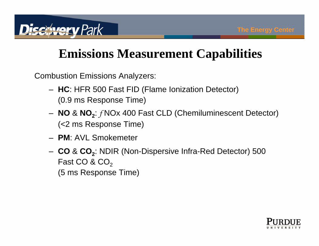
Emissions Measurement CapabilitiesCombustion Emissions Analyzers:
– HC: HFR 500 Fast FID (Flame Ionization Detector)(0.9 ms Response Time)
– NO & NO2: f NOx 400 Fast CLD (Chemiluminescent Detector)(<2 ms Response Time)
– PM: AVL Smokemeter
– CO & CO2: NDIR (Non-Dispersive Infra-Red Detector) 500 Fast CO & CO2(5 ms Response Time)

The Energy Center
Reaction Unit for Kinetic Measurements of After-Treatment Systems
MFC Controllers
NOx Analyzer
Mass Flow Meters
Reactor Oven
Mass Spectrometer
Turbo Pump
Temperature Display
Data Collection Module
Automatic Valves
Water Feeding Pump
Catalyst

The Energy Center
After-treatment Model DevelopmentImportant Assumptions
Laminar Flow Plug Flow
Complex porous catalyst washcoat
Flat support with deposited particles
Flat uniform surfaceBoundary Layer
Catalyst
NOx breakthrough curves
0
50
100
150
200
250
300
350
400
0 100 200 300 400 500 600 700 800 900 1000
Time /s
Con
cent
ratio
n /p
pm
0
5
10
15
20
0 5 10 15 20
Calculated Conversion %
Obs
erve
d Con
vers
ion
%
Oxidation predictions

The Energy Center
F-T Fuels in Diesel EnginesProposed Work
Evaluate F-T fuels and fuel blends of known properties; engine performance parameters, including emissions, will be measured.
Extend NOx after-treatment model for NO/NO2/CO/CO2/H2O inlet compositions that are relevant for diesel engine running on F-T fuels.

The Energy Center
F-T Fuels Utilization in Gas Turbines
Use of F-T fuel as an endothermic coolant for aircraft systems – endotherms and coking behavior must be investigated
Particulate generation – investigation of sooting behavior of F-T fuels and blends with JP8 – low aromatic content may lead to lower soot emissions
In general, atomization, mixing, ignition properties of F-T fuels and fuel blend must be studied systematically
Aircraft Gas Turbines

The Energy Center
F-T Fuels in Power-Generating Gas Turbines
Modern power-generating GT systems operate very fuel lean to reduce pollutant emissions – combustion stability of F-T fuels and fuel blends, pollutant formation at high pressure are areas of great interestActive control methods to reduce combustion instability must be developed Atomization, pre-mixing, fuel distributions in premixer/ignitor devices must be studied
F-T Fuels Utilization in Gas Turbines (continued)

The Energy Center
F-T Fuels Utilization in Gas Turbines
Rolls Royce Combustor Can
GT Combustor Facility in the High Pressure Laboratory

The Energy Center
Zucrow Lab Facilities for Gas Turbine Testing2000 actual cubic feet of 2,000 psi air storageRecently modernized air compressor plant
produces nearly 1 lbm/sec of dry air at 2,000 psiLarge natural gas fired heat exchanger capable of
950 deg F air discharge temperature at 9 lbm/sec and 700 psi
Precise flow rate and pressure control with large dome-loaded pressure regulator and sonic orifices, system blow-down performance well characterized
Recently upgraded emissions monitoring system, state-of-the-art FTIR and flame ionization detector installed
Laser diagnostic capabilities for probing harsh GT environment are being developed
HP Air Tanks
Laser Imaging of Fuel Spray

The Energy Center
Fuel Tank
N2
Flow MeterOil Bath
Preheater
Rope HeatersN2
T T
PT
WaterBath
T
PurgeValve
Run Valve
Preheater Valve
T
T
T
Filter
Dump Valve
WasteDrum Filter
T
Sample Collection
3-Way Valve
ControlValve
PT
PT
PT
Furnace
Cu
TT
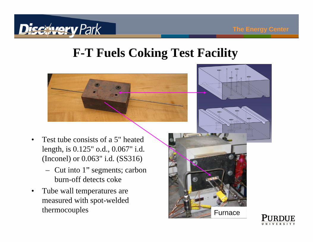
F-T Fuels Coking Test Facility
The Energy Center
F-T Fuels Coking Test Facility
• Test tube consists of a 5" heated length, is 0.125" o.d., 0.067" i.d. (Inconel) or 0.063" i.d. (SS316)– Cut into 1” segments; carbon
burn-off detects coke• Tube wall temperatures are
measured with spot-welded thermocouples Furnace

The Energy Center
Fuel Effects on Coking
JP-10
JP-8

The Energy Center
• Endothermmeasurement
• Product species• Coking rate• Resistively heated
reactor for simple endotherm calculation
Endothermic FuelExperimental Apparatus

The Energy Center
F-T Fuels in Gas Turbine EnginesProposed Work
Initiate studies on specifications of fuel for aircraft gas turbine engine use.
Identify desirable chemical structures for non-coking endothermic fuels.
Test coking properties of FT fuels and fuel blends.
Test ignition, performance, and emissions for FT fuels and fuel blends in Zucrow Laboratories gas turbine combustion facility.