usb stamp adapter board - ningapi.ning.com/.../28183usbstampadapterboardv1.11.pdf · the remote...
TRANSCRIPT
USB Stamp Adapter Board
User Manual
Engineering » Design » Product
Blue Wolf, Inc. 9179 W. State Street
Garden City, ID 83714

Engineering » Design » Product USB Stamp Adapter Board
Version 1.1 © 2011 Blue Wolf, Inc. Page 2 of 10
Revision History
Version # Release Date Revision/Release Comments
1.0 3/7/2011 Initial draft for release.
1.1 3/14/2011 Updated to include version table and FlashFly description.
1.11 4/5/2011 Update Assembly Steps.
The information contained in this publication, regarding device applications and/or use, is intended by way of suggestion only and may be superseded by updates or revisions.
No liability is assumed by Blue Wolf, Inc. with respect to the accuracy or use of such information or infringement of
patents arising from such use or their compliance to any industry standards.
The use of Blue Wolf, Inc. products as critical components in any life-saving system is not authorized except with express written approval. Safety glasses should always be worn when assembling this kit and care should be
exercised when using any soldering iron equipment or assembly tools.
This document is distributed by Blue Wolf, Inc. electronically and may not be printed and distributed without prior written permission.
Copyright © Blue Wolf, Inc. 2011. All rights reserved.

Engineering » Design » Product USB Stamp Adapter Board
Version 1.1 © 2011 Blue Wolf, Inc. Page 3 of 10
USB Stamp Adapter Board
#BWR-004-101
For USB Board of Education, USB Boe-Bot Robot, General BASIC Stamp Breadboarding, and FlashFly Use
Table of Contents The FlashFly System ...................................................................................................................................... 4
USB Stamp Adapter Board ............................................................................................................................ 5
Features ........................................................................................................................................................ 5
Key Specifications ......................................................................................................................................... 5
Kit Contents ................................................................................................................................................... 5
Tools Required .............................................................................................................................................. 5
Assembly Instructions ................................................................................................................................... 6
Connecting and Testing................................................................................................................................. 8
Connection Diagrams for USB Stamp Adapter Board ................................................................................... 9
Module Dimensions .................................................................................................................................... 10
Schematic Diagram for USB Stamp Adapter Board .................................................................................... 10

Engineering » Design » Product USB Stamp Adapter Board
Version 1.1 © 2011 Blue Wolf, Inc. Page 4 of 10
The FlashFly System
FlashFly is an innovative system that allows a user to remotely download BASIC Stamp programs to Parallax’s Stamp modules or interpreter chips. FlashFly’s wireless capabilities, in coordination with common Series 1 XBee modules, will allow a user with a BASIC Stamp mobile robot or stationary platform to modify his or her program remotely.
Therefore, individuals who have mobile robots, sprinkler systems, weather stations, alarm systems, or any other remote or fixed controller board with a BASIC Stamp core will benefit from the FlashFly system because wirelessly downloading a program change is now achievable and easy.
FlashFly eliminates the tedious task of having to connect a robot or a fixed platform to a computer before any programming changes can be made. FlashFly also enriches a user’s learning experience by providing instant feedback data to the DEBUG terminal screen, which allows a user to evaluate his or her program flow and I/O data wirelessly. FlashFly can also be used in conjunction with any other microprocessor platform that needs to transmit data wirelessly.
The two main components of the FlashFly system are the Base Module and the Remote Module. These two modules are responsible for communicating back and forth. In the FlashFly system, there are three options for the Remote Module component. Each of these options will allow for wireless downloading of BASIC Stamp programs.
1. The Remote Module can be inserted into a breadboard or user-defined board for direct communication with a BASIC Stamp interpreter chip.
2. The RS-232 serial adapter board can be used in the FlashFly system to connect to a mobile or fixed platform when the user has a serial BASIC Stamp version (a board that uses a DB-9 connecter).
3. The USB Stamp adapter module can be used in the FlashFly system to connect to the Remote Module when the user has a USB-type board with BASIC Stamp.
The following list identifies each of the FlashFly system components, their respective product numbers, and their role in FlashFly. The last two boards are interchangeable, depending on the BASIC Stamp version a user has.
Base Transmitter Board (BWR-001-101) – This board connects to the computer.
Remote Receiver Board (BWR-002-101) – This board connects to a mobile or fixed robot.
RS-232 Adapter Board (BWR-003-101) – This board connects to the remote board.
USB Stamp Adapter Board (BWR-004-101) – This board connects to the remote board.

Engineering » Design » Product USB Stamp Adapter Board
Version 1.1 © 2011 Blue Wolf, Inc. Page 5 of 10
USB Stamp Adapter Board
This is a low-cost USB Stamp adapter board that comes partially assembled. This cost-effective solution is an easy way to interface the FlashFly system to a USB Board of Education, a USB Boe-Bot, or for easy use in breadboarding a Stamp solution. With this board, and a FlashFly Base and Remote Module board, a user can wirelessly program his or her BASIC Stamp and have a means for wirelessly communicating with it. This product is perfect for experimenting with the Stamp in a breadboarding environment.
Features
On-board 5.0V regulator
Status indicator LEDs for power on
Works with FlashFly Remote Module
Key Specifications
Power requirements: 5.0 to 12.0 Vdc (Vin)
Operating temperature: -40 to +185F (-40 to 85 C)
Dimensions: 0.860‖ wide by 1.385‖ long
Kit Contents
BWR-004-101 PCB (1) — SMD components are pre-soldered
12 pin 0.100‖ Headers (2) — Solder to bottom of board
24 pin IC Socket for Stamp (1) — Solder to top of board
8 pin 0.100‖ Female Header (1) — Solder to top of board
Tools Required
Soldering iron (always wear safety glasses when soldering)
Solder (some soldering experience required)
Flux
Engineering » Design » Product USB Stamp Adapter Board
Version 1.1 © 2011 Blue Wolf, Inc. Page 6 of 10
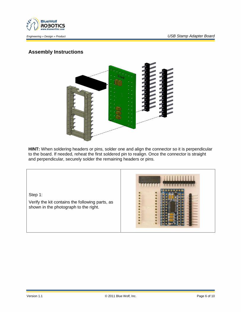
Assembly Instructions
HINT: When soldering headers or pins, solder one and align the connector so it is perpendicular to the board. If needed, reheat the first soldered pin to realign. Once the connector is straight and perpendicular, securely solder the remaining headers or pins.
Step 1:
Verify the kit contains the following parts, as shown in the photograph to the right.

Engineering » Design » Product USB Stamp Adapter Board
Version 1.1 © 2011 Blue Wolf, Inc. Page 7 of 10
Step 2:
Install both (2) 12 position 0.100‖ headers into the BOTTOM of the board. Once installed, solder them in place from the TOP of the board.
Step 3:
Install the 24 pin DIP socket on the TOP of the board. Once installed, solder it in place from the BOTTOM of the board.
Install the 8 pin Female Header on the TOP of the board. Once installed, solder it in place from the BOTTOM of the board.
Step 4:
Place the Stamp into the 24 pin DIP socket with the #1 pin of the Stamp toward the 8 position female header.
CAUTION: Do NOT get the USB Stamp adapter board wet. The 24 pin DIP socket from step 3 above is a ―wash away‖ socket. It is designed to have all the clear white portion of it disolve in water leaving only the pins. If by chance the assembly process was not adhered to and the 24 pin DIP socket was soldered onto the board first, prior to the bottom 2 headers from Step 2, then you will need to do the following:
Solder all the remaining pins on the 24 pin DIP socket. Then place your USB Stamp adapter in your dishwasher for a wash cycle. After the white portion in fully disolved and the board is dried, then you can carefully solder the bottom 2 headers in place.

Engineering » Design » Product USB Stamp Adapter Board
Version 1.1 © 2011 Blue Wolf, Inc. Page 8 of 10
Connecting and Testing
The USB Stamp adapter board has one (1) green LED on the bottom of the board. This LED is illuminated if the power is applied to the Vin pin or the Vdd pin. If 5.0 Vdc is needed for any external circuitry, the available current should be limited to 150 mA on the Vdd pin. If using a Series 1 X-Bee Pro module, usage should be limited to 50 mA.
The supply voltage (6.0 to 12.0 Vdc) can be connected to the Vin pin on the adapter board. If using a regulated 5.0 Vdc power supply, a user can connect it to the Vdd pin on the USB Stamp adapter board. However, in this instance, the Vin pin should not be connected.
CAUTION: The MCP1702 regulator used on Rev A of this adapter board is rated for a 250 mA continuous current. Vdd may be used as a 5.0 V supply output; however, be sure to limit the current use to approximately 150 mA. The rest of the current should be reserved for the FlashFly Remote module to ensure proper operation. If erratic operation occurs in the wireless functions, reduce the current consumption on the 5.0Vdc side (if using it).
Pin 24 – Vin Pin 23 – Vss Pin 22 – N/A Pin 21 - Vcc

Engineering » Design » Product USB Stamp Adapter Board
Version 1.1 © 2011 Blue Wolf, Inc. Page 9 of 10
Connection Diagrams for USB Stamp Adapter Board
The USB Stamp adapter board is primarily made for use with the FlashFly system to wirelessly download programs. However, the board also allows for an external RS-232 connection.
WARNING
Using an external RS-232 connection will disable the use of the FlashFly in-system downloading capabilities.
In order to connect to an external RS-232 connection, some of the solder pad jumpers (on the back side of the board) will have to be modified using an X-ACTO™ knife. First, cut the trace on SP1, SP2, and SP3 (SP4 is reserved for future use) from the middle pad to the right-side pad. Next, solder a jumper wire from the middle pad of each to the top-left pad. To restore it back for FlashFly operation, do the inverse.
Solder Pads

Engineering » Design » Product USB Stamp Adapter Board
Version 1.1 © 2011 Blue Wolf, Inc. Page 10 of 10
Module Dimensions
The USB Stamp adapter board measures 0.86‖ wide by 1.385‖ long.
Schematic Diagram for USB Stamp Adapter Board