use and maintenance manual - robinson...
TRANSCRIPT
USE AND MAINTENANCE MANUAL
INNOVA 65 B M 2011 INNOVA 75 B M 2011 INNOVA 85 B M 2011
INNOVA 100 B M 2011
ED. 10-2012 EN
ORIGINAL INSTRUCTIONS Doc. 10037757 Ver. AA

The descriptions contained in this document are not binding. The company therefore reserves the right to make any modifications at any time to elements, details, or accessory supply, as considered necessary for reasons of improvement or manufacturing/commercial requirements. The reproduction, even partial, of the text and drawings contained in this document is prohibited by law. The company reserves the right to make any technical and/or supply modifications. The images are for reference purposes only, and are not binding in terms of design and supply. Symbols used in the manual
Open book symbol with an "i" Indicates the need to consult the instruction manual
Open book symbol Used to tell the operator to read the manual before using the machine
Warning symbol Carefully read the sections marked with this symbol and observe the indications, for the safety of the operator and the machine
Warning symbol Indicates danger of gas exhalation and leakage of corrosive liquids
Warning symbol Indicates the danger of fire. Do not go near with free flames
Warning symbol Indicates that the packed product should be handled with suitable lifting means that comply with the legal requirements
Disposal symbol Carefully read the sections marked with this symbol, for machine disposal

3
CONTENTS
ON CONSIGNMENT OF THE MACHINE........................................................................................................................................................5 INTRODUCTORY COMMENT........................................................................................................................................................................5 INTENDED USE .............................................................................................................................................................................................5 SERIAL NUMBER PLATE...............................................................................................................................................................................5 TECHNICAL DESCRIPTION...........................................................................................................................................................................6 SYMBOLS USED ON THE MACHINE ............................................................................................................................................................7 GENERAL SAFETY REGULATIONS..............................................................................................................................................................9 MACHINE PREPARATION ...........................................................................................................................................................................10
1. HANDLING THE PACKAGED MACHINE .......................................................................................................................................................................... 10 2. HOW TO UNPACK THE MACHINE................................................................................................................................................................................... 10 3. HOW TO MOVE THE MACHINE ....................................................................................................................................................................................... 10 4. INSTRUMENT PANEL COMPONENTS ............................................................................................................................................................................ 10 5. STEERING COLUMN COMPONENTS.............................................................................................................................................................................. 11 6. FOOTBOARD FRONT-RIGHT COMPONENTS................................................................................................................................................................ 11 7. FOOTBOARD FRONT-LEFT COMPONENTS .................................................................................................................................................................. 11 8. MACHINE'S SIDE COMPONENTS.................................................................................................................................................................................... 11 9. MACHINE'S REAR COMPONENTS .................................................................................................................................................................................. 12 10. TYPE OF BATTERY......................................................................................................................................................................................................... 12 11. BATTERY MAINTENANCE AND DISPOSAL .................................................................................................................................................................. 12 12. FITTING THE BATTERIES INTO THE MACHINE........................................................................................................................................................... 12 13. BATTERY CONNECTION AND BATTERY CONNECTORS........................................................................................................................................... 13 14. BATTERY CHARGER CONNECTION (VERSIONS WITHOUT BC)............................................................................................................................... 13 15. BATTERY CHARGER CONNECTION (VERSIONS WITH CB) ...................................................................................................................................... 14 16. BATTERY CHARGE LEVEL INDICATOR ....................................................................................................................................................................... 16 17. WORKING FORWARD SPEED ....................................................................................................................................................................................... 16 18. REVERSE FUNCTION..................................................................................................................................................................................................... 16 19. RECOVERY TANK........................................................................................................................................................................................................... 16 20. SOLUTION TANK............................................................................................................................................................................................................. 16 21. FILLING THE SOLUTION TANK...................................................................................................................................................................................... 17 22. DETERGENT SOLUTION................................................................................................................................................................................................ 17 23. REGULATING THE DETERGENT................................................................................................................................................................................... 18 24. ASSEMBLING THE SQUEEGEE..................................................................................................................................................................................... 18 25. SQUEEGEE INCLINATION.............................................................................................................................................................................................. 18 26. ADJUSTING THE SQUEEGEE SUPPORT HEIGHT....................................................................................................................................................... 18 27. WASHING BASE CASING ASSEMBLY .......................................................................................................................................................................... 18 28. DISC BRUSH ASSEMBLY............................................................................................................................................................................................... 19 29. SERVICE BRAKE AND PARKING BRAKE ..................................................................................................................................................................... 19 30. BLINKING LIGHT (OPTIONAL)........................................................................................................................................................................................ 19 31. EMPTY SOLUTION TANK DEVICE................................................................................................................................................................................. 19
WORK ..........................................................................................................................................................................................................20 32. PREPARING TO WORK .................................................................................................................................................................................................. 20 33. OVERFLOW DEVICE....................................................................................................................................................................................................... 21
AT THE END OF THE WORK.......................................................................................................................................................................22 DAILY MAINTENANCE.................................................................................................................................................................................23
34. CLEANING THE RECOVERY TANK ............................................................................................................................................................................... 23 35. CLEANING THE SUCTION MOTOR FILTER.................................................................................................................................................................. 23 36. CLEANING THE SQUEEGEE.......................................................................................................................................................................................... 24 37. CLEANING THE SOLUTION TANK AND FILTER........................................................................................................................................................... 24 38. DISC BRUSH DISASSEMBLY......................................................................................................................................................................................... 25
WEEKLY MAINTENANCE ............................................................................................................................................................................26 39. CLEANING THE SUCTION TUBE ................................................................................................................................................................................... 26
EXTRAORDINARY MAINTENANCE.............................................................................................................................................................27 40. REPLACING THE FRONT SQUEEGEE RUBBER.......................................................................................................................................................... 27 41. REPLACING THE REAR SQUEEGEE RUBBER ............................................................................................................................................................ 27

4
42. REPLACEMENT OF THE BRUSH HEAD CASING......................................................................................................................................................... 27 TROUBLESHOOTING ..................................................................................................................................................................................28
43. INSUFFICIENT WATER ON THE BRUSHES.................................................................................................................................................................. 28 44. THE SQUEEGEE DOES NOT DRY PERFECTLY .......................................................................................................................................................... 28 45. THE MACHINE DOES NOT CLEAN WELL ..................................................................................................................................................................... 28 46. EXCESSIVE FOAM PRODUCTION ................................................................................................................................................................................ 28 47. THE SUCTION MOTOR DOES NOT FUNCTION ........................................................................................................................................................... 29 48. THE BRUSH MOTOR DOES NOT WORK ...................................................................................................................................................................... 29 49. THE MACHINE DOES NOT START ................................................................................................................................................................................ 29 50. ELECTRIC FUSES AND THERMAL CUT-OUTS ............................................................................................................................................................ 29
DISPOSAL....................................................................................................................................................................................................30 CHOOSING AND USING THE BRUSHES....................................................................................................................................................31 EC DECLARATION OF CONFORMITY ........................................................................................................................................................32

5
On consignment of the machine
When the machine is consigned to the customer, an immediate check must be performed to ensure all the material mentioned in the shipping documents has been received, and also to check the machine has not suffered damage during transportation. If this is the case, the carrier must ascertain the extent of the damage at once, informing our customer service office. It is only by prompt action of this type that the missing material can be obtained, and compensation for damage successfully claimed.
Introductory comment
INNOVA M 2011 is a scrubbing machine that is able to clean a wide variety of types of flooring and types of dirt by using the mechanical action of two disc or cylindrical brushes, depending on the model, and the chemical action of a water-detergent solution. As it advances, it also collects the dirt removed and the detergent solution not absorbed by the floor. The machine must be only used for this purpose. Even the best machines will only work well if used correctly and kept in good working order. We therefore suggest you to read this instruction booklet carefully and re-read it whenever difficulties arise while using the machine. If necessary, remember that our customer assistance service (organised in collaboration with our dealers) is always available for advice or direct intervention.
Intended use The scrubbing machine is exclusively designed for the professional cleaning of surfaces and floors in industrial, commercial and public environments. The machine is only suitable for use in closed (or at least covered) places. The machine is not suitable for use in the rain, or under water jets. It is FORBIDDEN to use the machine for picking up dangerous dusts or inflammable liquids within places with a potentially explosive atmosphere. In addition, it is not suitable as a means of transport for people or objects.
Serial number plate

6
TECHNICAL DESCRIPTION UM 65B 75B 85B 100B Working width mm 650 750 850 1010 Squeegee width mm 970 970 1085 1085 Working capacity, up to m2/h 3900 4500 5100 6000 Disk brush No. / ∅Ø 2 / 340 2 / 390 2 / 430 2 / 510 Brush rotations rpm 170 170 170 120 Brush motor V/W 24 / 450 24 / 450 24 / 450 24 / 600 Pressure on the brushes kg 30 30 30 30 Traction motor V / W 24 / 400 24 / 400 24 / 400 24 / 400 Traction wheel ∅ mm 220 220 220 220 Forward speed km/h 0¸6 0¸6 0¸6 0¸6 Maximum gradient with full load % 10 10 10 10 Suction motor V / W 24 / 310 24 / 310 24 / 310 24 / 310 Suction vacuum mbar 160 160 160 160 Rear elastic wheels ∅ mm 300x70 300x70 300x70 300x70 Solution tank l 110 110 110 110 Recovery tank l 125 125 125 125 Steering diameter mm 1910 1910 1910 1910 Machine length mm 1495 1495 1495 1495 Machine height mm 1320 1320 1320 1320 Machine width (without squeegee) mm 680 680 680 1035 Battery compartment (l x L x h) mm 384x520x340 Rated battery voltage V 24 24 24 24 Battery weight (max) kg 136 136 136 136 Machine weight (empty and without batteries) kg 223 223 223 230 Machine weight in running order (machine + batteries + water + operator) kg 550 550 550 555
Sound pressure level (ISO 11201) dB (A) - - - - Hand vibration level (ISO 5349) m/s2 - - - - Body vibration level (ISO 2631) m/s2 - - - -

7
SYMBOLS USED ON THE MACHINE
Main switch symbol (key switch) Used on the instrument panel, to indicate the key switch for machine operation on (I) or off (O)
Indicator showing battery charge level on the upper line and hour meter on the lower line
Indicator showing the type of hour meter (total) on the upper line and the type of service (none) on the lower line
Indicator showing the type of technology of the batteries used (lead)
Brush head / squeegee motion symbol (idle position) Used to indicate the movement levers of the brush head and squeegee
Brush head / squeegee motion symbol (working position) Used to indicate the movement levers of the brush head and squeegee
Pedal labels that indicate the forward and reverse direction of the machine Used to indicate the direction of the machine
Symbol denoting acoustic alarm Used to indicate the acoustic alarm button
Water quantity adjustment symbol Used on the steering column to indicate the knobs for adjusting the quantity of water distributed on the brushes
8
SYMBOLS USED ON THE MACHINE
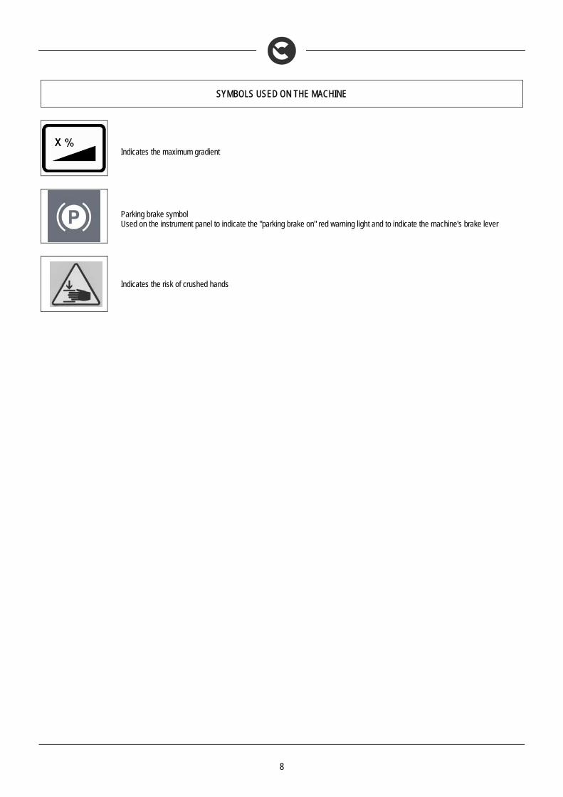
Indicates the maximum gradient
Parking brake symbol Used on the instrument panel to indicate the "parking brake on" red warning light and to indicate the machine's brake lever
Indicates the risk of crushed hands

9
GENERAL SAFETY REGULATIONS
The regulations below must be carefully followed in order to avoid harm to the operator and damage to the machine. • Read the labels on the machine carefully. Do not cover them for any reason and replace them immediately if they become damaged. • The machine must be exclusively used by authorised, trained personnel. • The machine is designed for dry use only and should not be used or kept outdoors in damp conditions. • Disconnect from the mains/battery before performing cleaning or maintenance operations on the machine. • If the machine is used where there is a risk of falling objects, the machine must be equipped with protections against falling objects. • During the working of the machine, pay attention to other people and especially to children. • The machine is not suitable for cleaning carpets. • Do not mix different types of detergent as this may produce harmful gases. • Do not place any liquid containers on the machine. • The storage temperature must be between -25°C and +55°C; do not store outdoors in damp conditions. • Conditions of use: room temperature between 0°C and 40°C with relative humidity between 30 and 95%. • Do not use the machine in an explosive atmosphere. • Do not use the machine as a means of transport. • Do not use acid solutions that could damage the machine and/or harm people. • Do not vacuum inflammable liquids. • Do not use the device to collect dangerous powders. • In the event of a fire, use a powder extinguisher. Do not use water. • Do not knock against shelving or scaffolding, where there is a danger of falling objects. Use protective devices (helmet). • Adapt the speed to the adhesion conditions. • Do not use the machine on surfaces with an inclination greater than the one shown on the plate. • When the machine is in parking mode, remove the key and engage the parking brake. • If you notice any damage to the battery charger cable, contact a COMAC technical assistance centre immediately. • The machine is designed to carry out the washing and drying operations simultaneously. Different operations should only be carried out in areas where
the passage of unauthorised persons is prohibited. Signal the presence of damp floors with suitable signs. • If the machine does not work properly, check this is not caused by failure to carry out routine maintenance. Otherwise, request the intervention of the
COMAC technical assistance centre. • If you need to replace any components, request the ORIGINAL spare parts from a COMAC dealer and/or Authorised Retailer. • Use original COMAC brushes only indicated in the paragraph “CHOOSING AND USING THE BRUSHES". • In the event of danger, activate the emergency lever (connector placed under the operator's seat) immediately. • Before carrying out any maintenance work, switch off the machine and disconnect the battery connector. • Restore all electrical connections after any maintenance interventions. • Do not remove any protection devices which require the use of tools in order to be removed. • Do not wash the machine with direct water jets or with pressurised water, nor with corrosive substances. • After at least every 200 hours of operation, have the machine checked by a COMAC assistance centre. • To prevent scaling in the solution tank filter, do not fill the tank with detergent solution many hours before using the machine. • Before using the machine, check that all the hatches and covers are positioned as shown in this Use and Maintenance Manual. • Make sure the recovery tank is empty before lifting. • When disposing of consumption materials, observe the laws and regulations in force. • The machine does not cause harmful vibrations. • When your COMAC machine has reached the end of its long working life, dispose of the materials it contains (especially oils, batteries and electronic
components) in an appropriate manner, and bearing in mind that the machine itself was constructed using 100% recyclable materials. • The batteries must be removed from the machine before its disposal. • The batteries must be disposed of in a safe manner, fully observing the laws and regulations in force. • The machine is not suitable for use by children and persons with reduced physical, mental and sensory capabilities, or people who lack experience and
knowledge. • Children must be supervised to ensure they do not play with the device. • When the machine if left unattended, engage the parking brake for safety against unintentional movements.

10
MACHINE PREPARATION
1. HANDLING THE PACKAGED MACHINE
The machine is contained in specific packaging with a pallet for the handling with fork trucks. The packages cannot be placed on top of each other. The total mass of the machine with packaging is 240 kg (without batteries) The dimensions of the packaging is as follows:
65-75-85-100 B
A: 1610mm B: 730mm C: 1600mm
A
C B
2. HOW TO UNPACK THE MACHINE
1. Remove the outer packaging 2. The machine is fixed to the pallet with wedges which block the wheels 3. Remove the wedges
4. Use a chute to get the machine down from the pallet, pushing it backwards. Do not assemble the rear
squeegee before unloading the machine, and avoid violently jolting the brush head. To assemble the squeegee, read the “ASSEMBLING THE SQUEEGEE” paragraph.
5. Keep the pallet for any future transport needs
WARNING: if the product is delivered in cardboard containers, handle the packed product with suitable lifting means that comply with the legal requirements
3. HOW TO MOVE THE MACHINE
1. Make sure the recovery tank and the solution tank are empty 2. Check that the base and squeegee are lifted off the ground 3. Place it on a pallet using a chute 4. Check that the key switch is on OFF and remove the key 5. Engage the parking brake 6. Secure the machine to the pallet using wooden wedges
4. INSTRUMENT PANEL COMPONENTS
The instrument panel components are identified as follows: 1. Battery level / hour-counter display 2. Battery level hour meter display control button 3. Main key switch 4. Red warning light indicating that the parking brake is on
1
2
4
3

11
MACHINE PREPARATION
5. STEERING COLUMN COMPONENTS
The steering column components are identified as follows: 5. Squeegee body lifting lever 6. Brush head body lifting lever 7. Horn button 8. Detergent solution adjustment lever
6. FOOTBOARD FRONT-RIGHT COMPONENTS
The components at the front right of the footboard are identified as follows:
9. Accelerator pedal, forward 10. Accelerator pedal, reverse
WARNING:Only by simultaneously pressing the pedals is the reverse made
7. FOOTBOARD FRONT-LEFT COMPONENTS
The components at the front right of the footboard are identified as follows: 11. Service brake pedal 12. Parking brake lever
8. MACHINE'S SIDE COMPONENTS
The side components of the machine are identified as follows: 13. Water-detergent filler cap 14. Water filler cap
15. Water-detergent drainage cap
8
7
6
5
11 12
15
10 9
13
14

12
MACHINE PREPARATION
9. MACHINE'S REAR COMPONENTS
The rear components of the machine are identified as follows: 16. Recovery tank discharge cap
10. TYPE OF BATTERY
To power the machine it is necessary to use: • liquidelectrolyte lead traction batteries; • sealed traction batteries with gas recombination or gel technology.
OTHER TYPES MUST NOT BE USED. The batteries must meet the requirements laid out in the norms: CEI EN 60254-1:2005-12 (CEI 21-5) + CEI EN 60254-2:2008-06 (CEI 21-7) The battery compartment can house four 6V or two 12V batteries For a good operating performance, we suggest the use of four 6V/210 Ah C5 batteries
11. BATTERY MAINTENANCE AND DISPOSAL
For maintenance and recharging, comply with the instructions provided by the battery manufacturer. Particular attention must be paid when choosing the battery charger, if not supplied, since there are different kinds according to the type and capacity of the battery. When the battery reaches the end of its working life, it must be disconnected by expert, trained personnel, then lifted (using the grips and suitable lifting devices) to remove it from the battery compartment. DEAD BATTERIES ARE CLASSIFIED AS DANGEROUS WASTE AND MUST BE DELIVERED TO THE AUTHORISED BODIES FOR CORRECT DISPOSAL.
WARNING: You are advised to always wear protective gloves, to avoid the risk of serious injury to your hands.
WARNING: You are advised to only lift and move the batteries with lifting and transportation means suitable for the specific weight and size
12. FITTING THE BATTERIES INTO THE MACHINE
The batteries must be housed in the special compartment beneath the recovery tank. They should be handled using lifting equipment that is suitable in terms of both weight and hook-up system. They must also satisfy the requirements of Standard CEI 21-5. The dimensions of the battery compartment are: 384 x 520 x H340 mm.
WARNING: For battery maintenance and daily recharging, you must fully respect the indications provided by the manufacturer or retailer. All installation and maintenance operations must be carried out by specialised personnel.
16

13
MACHINE PREPARATION
To insert the batteries you must: 1. Lock the machine engaging the brake lever 2. Make sure that the key switch is in the “OFF” position 3. Make sure the recovery tank is empty, otherwise empty it completely 4. Grip the handle under the seat to open the recovery tank 5. Lift the recovery tank until it hooks to the end of the safety clamp 6. house the batteries in the compartment, positioning the poles “+” and “-“ opposite each other
WARNING: you are advised to use airtight batteries only, to avoid the leakage of acids!
ATTENTION: you are advised to always wear protective gloves, to avoid the risk of serious injury to your hands.
ATTENTION: You are advised to only lift and move the batteries with lifting and transportation means suitable for the specific weight and size
13. BATTERY CONNECTION AND BATTERY CONNECTORS
1. connect the batteries in series - using the jumper cables supplied (3) - to the poles “+” and “-“ 2. Connect the battery connector cable (1) to the terminal poles “+” and “-“ to obtain a voltage of 24V on
the clamps 3. Connect the battery connector (1) to the machine connector (2).
ATTENTION: you are advised to have the electric connections made by a qualified, COMAC-trained technician
ATTENTION: you are advised to always wear protective gloves, to avoid the risk of serious injury to your hands.
14. BATTERY CHARGER CONNECTION (VERSIONS WITHOUT BC)
In order not to cause permanent damage to the batteries it is essential to avoid their complete discharge: arrange the recharge within a few minutes of the switching on of the flashing "discharged batteries" signal.
ATTENTION: never leave the batteries completely discharged, even if the machine is not being used. Check the battery charger is suitable for the batteries installed, in terms of both capacity and type.
3

14
MACHINE PREPARATION
To connect the batteries you must:
1. Make sure the recovery tank is empty, otherwise empty it completely 2. Make sure that the key switch is in the “OFF” position 3. Move the machine near to the battery charger 4. Engage the parking brake 5. Grip the handle under the seat to open the recovery tank 6. Lift the recovery tank until it hooks to the end of the safety clamp
7. Disconnect the electrical connector from the battery connector (1) from the machine connector (2) 8. Connect the battery charger cable connector 9. Close the recovery tank until the prop is hooked in the first point of the safety stop
The coupling connector of the battery charger is consigned inside the bag containing this instruction booklet, and must be assembled on the cables of the battery charger as indicated in the instructions.
ATTENTION: this process must be carried out by qualified personnel. An incorrect connection of the connector may cause problems with machine functioning.
10. Connect the recently wired cable to the external battery charger
WARNING: Carefully read the use and maintenance instructions of the battery charger that is used for charging. In addition, check that the battery charger is compatible with the batteries used.
WARNING: Keep the recovery tank open for the duration of the battery recharging cycle to allow gas fumes to escape
11. After recharging the batteries completely, the battery connector (1) must be connected to the machine connector (2)
ATTENTION: danger of exhalation of gas and leakage of corrosive liquids.
ATTENTION: danger of fire: do not go near with free flames
15. BATTERY CHARGER CONNECTION (VERSIONS WITH CB)
In order not to cause permanent damage to the batteries it is essential to avoid their complete discharge: arrange the recharge within a few minutes of the switching on of the flashing "discharged batteries" signal.
ATTENTION: never leave the batteries completely discharged, even if the machine is not being used. Check the battery charger is suitable for the batteries installed, in terms of both capacity and type.

15
MACHINE PREPARATION
To connect the batteries you must: 1. Make sure the recovery tank is empty, otherwise empty it completely 2. Make sure that the key switch in the “0” position 3. Move the machine near to the battery charger 4. Engage the parking brake 5. Grip the handle under the seat to open the recovery tank 6. Lift the recovery tank until it hooks to the end of the safety clamp
7. Remove the protective sheath (1), pulling it toward the rear of the machine until the screw (2) can
pass through the slot present on the sheath 8. Connect the battery charger cable to the socket on the charger itself 9. Close the recovery tank until the prop is hooked in the first point of the safety stop 10. Plug the battery charger cable into the mains socket.
The charger power cable is delivered inside the bag containing this instruction booklet.
WARNING: This process must be carried out by qualified personnel. An incorrect connection of the connector may cause problems with machine functioning.
WARNING: Carefully read the use and maintenance manual of the charger that is delivered inside the bag containing this instruction booklet. In addition, check that the battery charger is compatible with the batteries used.
WARNING: Before inserting the charger power cable into the socket, verify that there is no condensate or other forms of liquids.
ATTENTION: the machine is equipped with an automatic system that disconnects the power supply from the electrical system while the batteries are being recharged ATTENTION: in order not to cause permanent damage to the batteries it is essential to avoid their complete discharge: arrange the recharge within a few minutes of the switching on of the flashing "discharged batteries" signal. ATTENTION: never leave the batteries completely discharged, even if the machine is not being used. ATTENTION: for the daily recharging of the batteries, you must fully respect the indications provided by the manufacturer or retailer. All installation and maintenance operations must be carried out by specialised personnel. ATTENTION: Always make sure the green LED of the battery charger is on before using the machine again
ATTENTION: danger of exhalation of gas and leakage of corrosive liquids.
ATTENTION: danger of fire: do not go near with free flames
2
1

16
MACHINE PREPARATION
16. BATTERY CHARGE LEVEL INDICATOR
On the instrument panel of the machine there is a monitor (1) indicating (amongst other things) the battery charge status. If the upper line contains 8 light indicators, the battery charge level is 100%. If the edges of the indicators are flashing, this means the batteries are run down.
ATTENTION: a few seconds after the last indicator on the monitor has flashed, the brush motor will automatically switch off. With the remaining charge it is possible to complete the drying process before recharging
17. WORKING FORWARD SPEED
This machine is equipped with electronic traction control. To move the machine, after having turned the key in the ON position, push the drive pedal (6) adjusting the speed by pressing and releasing the pedal. The machine will then start moving.
18. REVERSE FUNCTION
To make a reversing manoeuvre, press both pedals (6 and 7) the machine will then start moving backwards. During reverse motion, the machine emits an acoustic signal.
19. RECOVERY TANK
Make sure the recovery tank is empty, otherwise empty it completely. Check the cap of the drainage tube (10) (on the rear of the machine) is correctly closed.
20. SOLUTION TANK
The recovery tank must be completely empty each time the solution tank is filled. Remove the front inlet cap and check the solution filter is correctly fitted. Check that the solution filter cap (1), under the solution tank in the front right of the machine, is properly closed.
1
1
17
MACHINE PREPARATION
21. FILLING THE SOLUTION TANK
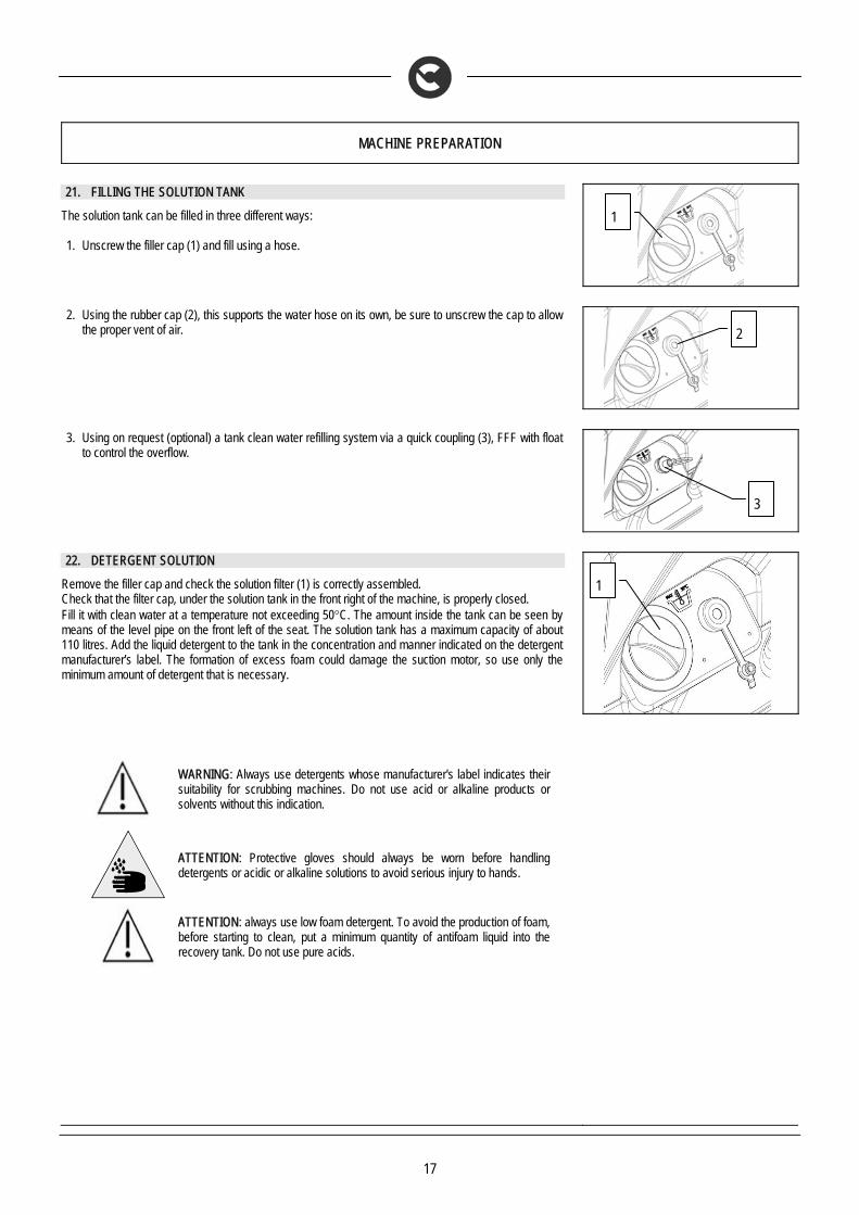
The solution tank can be filled in three different ways: 1. Unscrew the filler cap (1) and fill using a hose.
2. Using the rubber cap (2), this supports the water hose on its own, be sure to unscrew the cap to allow
the proper vent of air.
3. Using on request (optional) a tank clean water refilling system via a quick coupling (3), FFF with float
to control the overflow.
22. DETERGENT SOLUTION
Remove the filler cap and check the solution filter (1) is correctly assembled. Check that the filter cap, under the solution tank in the front right of the machine, is properly closed. Fill it with clean water at a temperature not exceeding 50°C. The amount inside the tank can be seen by means of the level pipe on the front left of the seat. The solution tank has a maximum capacity of about 110 litres. Add the liquid detergent to the tank in the concentration and manner indicated on the detergent manufacturer's label. The formation of excess foam could damage the suction motor, so use only the minimum amount of detergent that is necessary.
WARNING: Always use detergents whose manufacturer's label indicates their suitability for scrubbing machines. Do not use acid or alkaline products or solvents without this indication.
ATTENTION: Protective gloves should always be worn before handling detergents or acidic or alkaline solutions to avoid serious injury to hands.
ATTENTION: always use low foam detergent. To avoid the production of foam, before starting to clean, put a minimum quantity of antifoam liquid into the recovery tank. Do not use pure acids.
2
1
1
3

18
MACHINE PREPARATION
23. REGULATING THE DETERGENT
Firstly, fully open the outflow of the tap, by means of the lever (3) on the steering column. During the first few meters, check that the amount of solution to wet the floor is sufficient, but not too much that it exits the splash-guard, the adjustment of the detergent application is made by means of lever (3) (shifting it downwards increases the flow, shifting it upwards decreases it). Bear in mind that the correct amount of solution is always depends on the nature of the floor, the degree of dirt and the forward speed.
24. ASSEMBLING THE SQUEEGEE
For packaging reasons, the squeegee is supplied disassembled from the machine, and must be assembled as shown in the figure. Raise the squeegee connection by means of the left lever (1) turning it clockwise into the vertical position. Make sure the parking brake is engaged and that the main switch is OFF. First thread left pin (2) of the squeegee into the left slot on the arm and then right pin (3) into the right slot, being careful to keep the spring and the washer above the arm’s flat bar. This can be simplified by first loosening the handwheel on the pin. Then re-tighten the handwheel to block the squeegee in place. Insert the squeegee tube in the appropriate sleeve (4).
25. SQUEEGEE INCLINATION
During working operation, the rear rubber is slightly tilted backwards (by about 5mm) in a uniform way for its whole length. If it is necessary to increase the bend of the rubber in the central part, you must tilt the squeegee backwards, rotating the adjuster screw (1) clockwise.
26. ADJUSTING THE SQUEEGEE SUPPORT HEIGHT
The height of the squeegee must be adjusted on the basis of the state of wear and tear of the rubber. Carry out the following operations for adjustment: 1. unscrew the locking nut 2. raise or lower the wheel (1) by sliding it on the slot of the support 3. block it by tightening the locking nut once the required height is reached.
Note: To facilitate the operation, completely lower the squeegee and put a spacer of a few millimetres (2 to 4 mm depending on the type of rubber) under the wheel.
27. WASHING BASE CASING ASSEMBLY
The casing of the washing base that for reasons of packaging are supplied disassembled from the machine, must be mounted as shown. Make sure the parking brake is engaged and that the main switch is OFF. Unscrew the 8 screws on the base (4 per side). Position the two casings (right and left) and secure them with the previously removed screws.

19
MACHINE PREPARATION
28. DISC BRUSH ASSEMBLY
1. Make sure the parking brake is engaged and that the main switch is OFF 2. Connect the battery connector 3. Turn the key to the "ON/I" position. The base raises automatically. 4. Turn the key to the “OFF/0” position and remove it from the electrical board.
WARNING: during this operation, verify that there are no people or objects near the brush.
5. With the base up, insert the brushes in the plate housing beneath the base, turning them until the three pins enter the niches in the plate itself; turn until the pin is pushed towards the coupling spring and is locked into place. The photo shows the rotation direction to hook up the right-hand brush; for the left-hand one, rotate in the opposite direction.
ATTENTION: You are advised to always wear protective gloves, to avoid the risk of serious injury to your hands.
You are advised to invert the right and left-hand brushes every day. If the brushes are not new however, and have deformed bristles, it is better to reassemble them in the same position (the right-hand one on the right, and the left-hand one on the left), to prevent the different inclination of the bristles producing an overload on the brush motor as well as excessive vibrations.
29. SERVICE BRAKE AND PARKING BRAKE
The machine has an electronic braking system. To brake, in normal conditions, just remove your foot from the accelerator pedal. If this service brake is working badly, or if necessary, activate the brake pedal (13) pushing it downwards. To engage the parking brake, press the brake pedal (13) and lock it by pulling the lever (14) to the left. The red indicator light on the instrument panel will switch on.
WARNING: to avoid any damage to the machine, always disengage the parking brake before beginning to work or before making any transfer manoeuvres
30. BLINKING LIGHT (OPTIONAL)
The machine can be equipped with a blinking light that turns on automatically when the key in the main switch is turned on.
31. EMPTY SOLUTION TANK DEVICE
To check the quantity of water in the solution tank there is a special level indicator tube (5) next to the driver's seat.

20
WORK
32. PREPARING TO WORK
1. Make sure the recovery tank is empty, otherwise empty it completely 2. Check that the main switch of the machine is set to "0" 3. Connect the connector to the batteries (1) 4. Sit on the driver’s seat
5. Check the parking brake is released (2). 6. Turn the key of the main switch a quarter of a turn clockwise (to position ON). Immediately, on the
instrument panel, the display will turn on indicating the charge level of the batteries.
7. With switch-on, three consecutive screens are displayed on the monitor. The first screen shows (on
the top line) what type of hour-counter has been set; in this case it is a total hour-counter (to display a different type - for instance partial - contact the qualified, COMAC-trained personnel). The bottom line shows the “service” setting (in this case there is no setting).
8. The second screen displays what battery technology has been set for machine operation; in this
case it is lead batteries (to set another type of battery - for instance gel - contact the qualified, COMAC-trained personnel).
9. The third and last screen (known as “work”) displays the battery charge status and the total
functioning time. When the batteries supplied are fully charged, the upper line contains 8 light indicators that represent a battery. As the batteries gradually run down, the indicators go out and, with the batteries completely run down, only the battery outline flashes. The bottom line indicates the hours and minutes of functioning. The flashing “:” symbol indicates that the hour-counter is counting the machine functioning time.
10. Move the tap lever (3) downwards and adjust to the desired solution quantity.
21
WORK
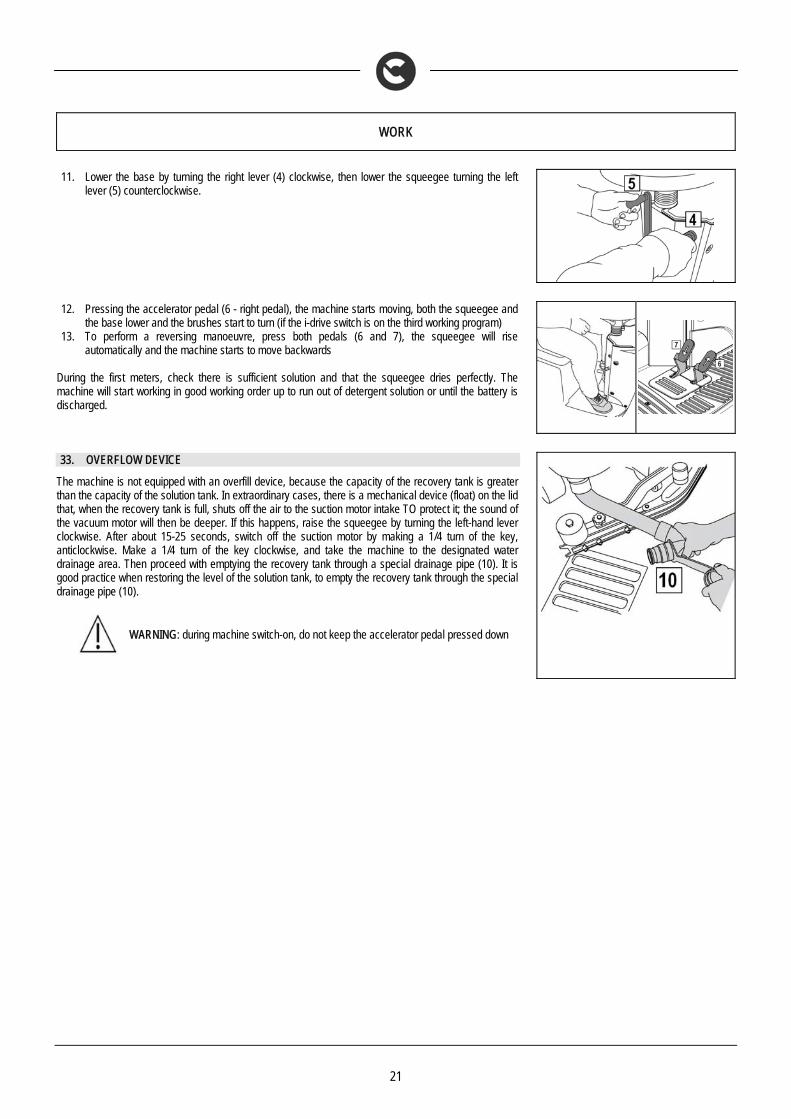
11. Lower the base by turning the right lever (4) clockwise, then lower the squeegee turning the left
lever (5) counterclockwise.
12. Pressing the accelerator pedal (6 - right pedal), the machine starts moving, both the squeegee and
the base lower and the brushes start to turn (if the i-drive switch is on the third working program) 13. To perform a reversing manoeuvre, press both pedals (6 and 7), the squeegee will rise
automatically and the machine starts to move backwards During the first meters, check there is sufficient solution and that the squeegee dries perfectly. The machine will start working in good working order up to run out of detergent solution or until the battery is discharged.
33. OVERFLOW DEVICE
The machine is not equipped with an overfill device, because the capacity of the recovery tank is greater than the capacity of the solution tank. In extraordinary cases, there is a mechanical device (float) on the lid that, when the recovery tank is full, shuts off the air to the suction motor intake TO protect it; the sound of the vacuum motor will then be deeper. If this happens, raise the squeegee by turning the left-hand lever clockwise. After about 15-25 seconds, switch off the suction motor by making a 1/4 turn of the key, anticlockwise. Make a 1/4 turn of the key clockwise, and take the machine to the designated water drainage area. Then proceed with emptying the recovery tank through a special drainage pipe (10). It is good practice when restoring the level of the solution tank, to empty the recovery tank through the special drainage pipe (10).
WARNING: during machine switch-on, do not keep the accelerator pedal pressed down
22
AT THE END OF THE WORK
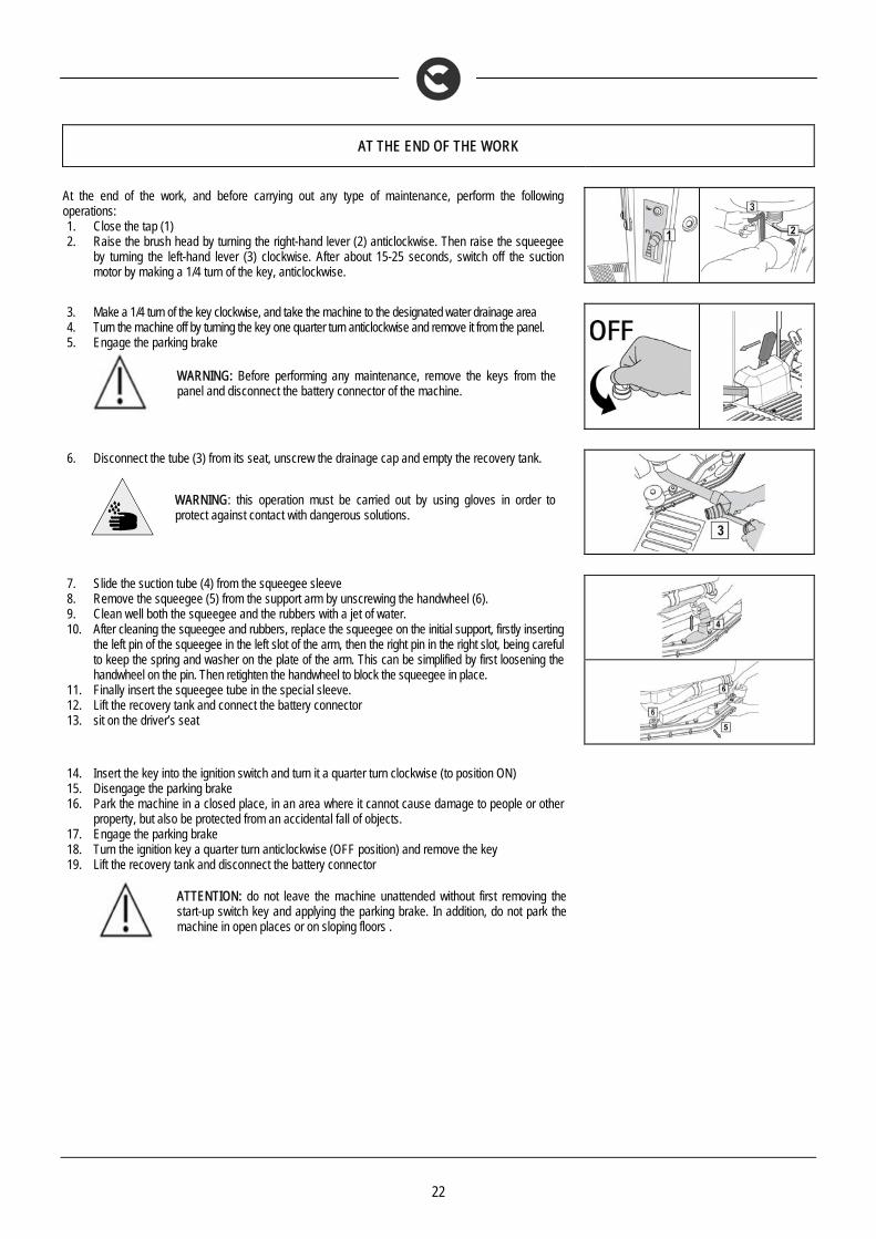
At the end of the work, and before carrying out any type of maintenance, perform the following operations: 1. Close the tap (1) 2. Raise the brush head by turning the right-hand lever (2) anticlockwise. Then raise the squeegee
by turning the left-hand lever (3) clockwise. After about 15-25 seconds, switch off the suction motor by making a 1/4 turn of the key, anticlockwise.
3. Make a 1/4 turn of the key clockwise, and take the machine to the designated water drainage area 4. Turn the machine off by turning the key one quarter turn anticlockwise and remove it from the panel. 5. Engage the parking brake
WARNING: Before performing any maintenance, remove the keys from the panel and disconnect the battery connector of the machine.
6. Disconnect the tube (3) from its seat, unscrew the drainage cap and empty the recovery tank.
WARNING: this operation must be carried out by using gloves in order to protect against contact with dangerous solutions.
7. Slide the suction tube (4) from the squeegee sleeve 8. Remove the squeegee (5) from the support arm by unscrewing the handwheel (6). 9. Clean well both the squeegee and the rubbers with a jet of water. 10. After cleaning the squeegee and rubbers, replace the squeegee on the initial support, firstly inserting
the left pin of the squeegee in the left slot of the arm, then the right pin in the right slot, being careful to keep the spring and washer on the plate of the arm. This can be simplified by first loosening the handwheel on the pin. Then retighten the handwheel to block the squeegee in place.
11. Finally insert the squeegee tube in the special sleeve. 12. Lift the recovery tank and connect the battery connector 13. sit on the driver’s seat
14. Insert the key into the ignition switch and turn it a quarter turn clockwise (to position ON) 15. Disengage the parking brake 16. Park the machine in a closed place, in an area where it cannot cause damage to people or other
property, but also be protected from an accidental fall of objects. 17. Engage the parking brake 18. Turn the ignition key a quarter turn anticlockwise (OFF position) and remove the key 19. Lift the recovery tank and disconnect the battery connector
ATTENTION: do not leave the machine unattended without first removing the start-up switch key and applying the parking brake. In addition, do not park the machine in open places or on sloping floors .

23
DAILY MAINTENANCE
PERFORM ALL MAINTENANCE OPERATIONS IN SEQUENCE 34. CLEANING THE RECOVERY TANK
1. Disconnect the tube (1) from its seat, unscrew the drainage cap and empty the recovery tank.
ATTENTION: Before performing any maintenance, remove the keys from the panel and disconnect the battery connector of the machine.
WARNING: this operation must be carried out wearing gloves to protect against contact with dangerous solutions.
2. Raise the cap (2) until the hook (4) is secured to the prop (3) of the recovery tank. 3. Clean and rinse the recovery tank and the suction pipe (connecting pipe between the squeegee
and the tank). 4. Reposition the cap on the drainage tube and lower the suction cap. To lock the prop (3) just
slightly raise the cap, release the prop (3) and lower the cap up to close it.
35. CLEANING THE SUCTION MOTOR FILTER
1. Raise the suction cover (2) and block it with the stop (3) 2. Remove the suction filter protection (5) by rotating it clockwise 3. Release the retaining clips (6) 4. Remove the suction filter (7) from its seat 5. Use a jet of water to clean the walls and brush head of the filter 6. Reassemble all the elements
ATTENTION: These operations must be carried out using gloves to protect against contact with dangerous solutions.
ATTENTION: Before performing any maintenance, remove the keys from the panel and disconnect the battery connector of the machine.
6
7
2
4
3
5

24
DAILY MAINTENANCE
36. CLEANING THE SQUEEGEE
The careful cleaning of the whole vacuum unit ensures better drying and cleaning of the floor as well as greater duration of the suction motor. Proceed as follows for cleaning: 1. Slide the suction tube (1) from the squeegee sleeve. 2. Remove the squeegee (2) from the support arm by unscrewing the handwheel (3). 3. Check the wear of the rubbers. If the edge of the rubber is ruined, the rear rubber can be turned
on all four corners. If the rubbers are completely worn proceed with the replacement. To remove the rubber, turn the wing nuts (4) in a horizontal position, remove the rubber-pressing blade (5) and then remove the rubber to turn it or replace it.
4. Proceed in reverse to replace the rubber. 5. After cleaning, replace the squeegee (2) on the initial support, firstly inserting the left pin of the
squeegee in the left slot of the arm, then the right pin in the right slot, being careful to keep the spring and washer on the plate of the arm. This can be simplified by first loosening the handwheel (3) on the pin. Then retighten the handwheel (3) to block the squeegee in place
6. Finally insert the squeegee tube in the special sleeve.
ATTENTION: Before performing any maintenance, remove the keys from the panel and disconnect the battery connector of the machine.
ATTENTION: These operations must be carried out using gloves to protect against contact with dangerous solutions.
37. CLEANING THE SOLUTION TANK AND FILTER
1. Disconnect the clean water drainage pipe (1) from its housing on the left side of the machine, unscrew the cap and empty the tank.
2. Remove the plug from the solution tank refill opening. 3. Rinse the inside of the tank with a jet of water. 4. Close the drainage pipe with the cap and put it in place. 5. Close the water tap (2). 6. Unscrew the filter (3) at the front of the machine. 7. Remove the internal filter cartridge and rinse everything thoroughly with running water. 8. Reassemble all the elements.
ATTENTION: Before performing any maintenance, remove the keys from the panel and disconnect the battery connector of the machine.
ATTENTION: These operations must be carried out using gloves to protect against contact with dangerous solutions.
25
DAILY MAINTENANCE
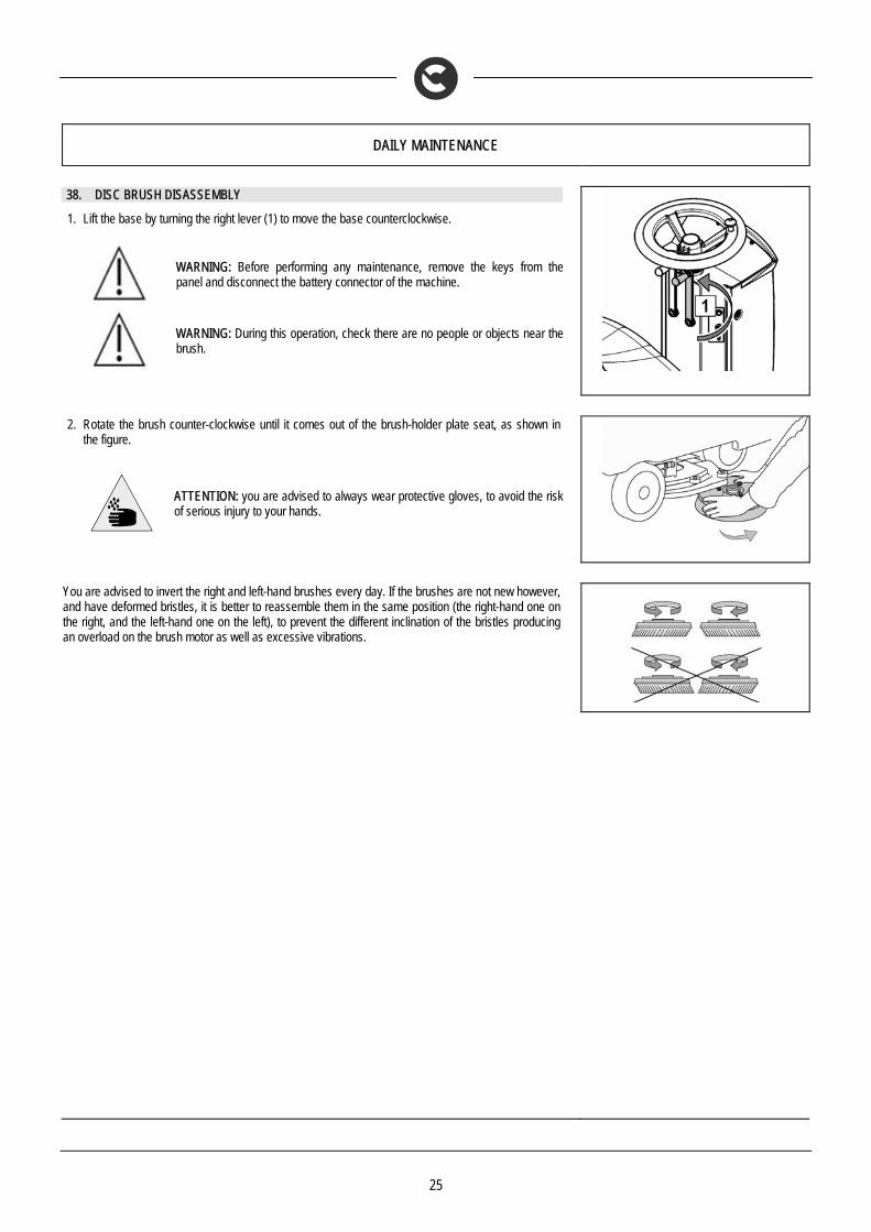
38. DISC BRUSH DISASSEMBLY
1. Lift the base by turning the right lever (1) to move the base counterclockwise.
WARNING: Before performing any maintenance, remove the keys from the panel and disconnect the battery connector of the machine.
WARNING: During this operation, check there are no people or objects near the brush.
2. Rotate the brush counter-clockwise until it comes out of the brush-holder plate seat, as shown in
the figure.
ATTENTION: you are advised to always wear protective gloves, to avoid the risk of serious injury to your hands.
You are advised to invert the right and left-hand brushes every day. If the brushes are not new however, and have deformed bristles, it is better to reassemble them in the same position (the right-hand one on the right, and the left-hand one on the left), to prevent the different inclination of the bristles producing an overload on the brush motor as well as excessive vibrations.

26
WEEKLY MAINTENANCE
39. CLEANING THE SUCTION TUBE
Whenever suction seems to be unsatisfactory, check that the suction tube (1) is not obstructed. If necessary clean with a jet of water as follows: 1. Make sure the recovery tank is empty, otherwise empty it 2. Turn the key to the “OFF/0” position and remove it from the electrical board 3. Raise the squeegee body from the ground by turning lever (5) clockwise 4. Raise the brush head body from the ground by turning lever (4) counter-clockwise
5. Remove the tube from the squeegee suction nozzle 6. Grip the handle under the seat to open the recovery tank 7. Lift the recovery tank until it hooks to the end of the safety clamp 8. Detach the aspiration tube from the seat on the recuperation tank (1) 9. Clean it with a water jet introduced from the side where it is connected to the tank 10. Reassemble all the elements
WARNING: Before performing any maintenance, remove the keys from the panel and disconnect the battery connector of the machine.
WARNING: This operation must be carried out using gloves to protect against contact with dangerous solutions.
1
27
EXTRAORDINARY MAINTENANCE
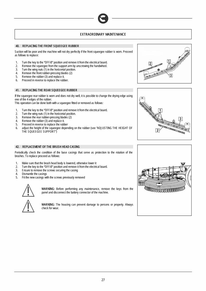
40. REPLACING THE FRONT SQUEEGEE RUBBER
Suction will be poor and the machine will not dry perfectly if the front squeegee rubber is worn. Proceed as follows to replace: 1. Turn the key to the “OFF/0” position and remove it from the electrical board. 2. Remove the squeegee from the support arm by unscrewing the handwheel. 3. Turn the wing nuts (1) in the horizontal position. 4. Remove the front rubber-pressing blades (2) 5. Remove the rubber (3) and replace it. 6. Proceed in reverse to replace the rubber.
41. REPLACING THE REAR SQUEEGEE RUBBER
If the squeegee rear rubber is worn and does not dry well, it is possible to change the drying edge using one of the 4 edges of the rubber. This operation can be done both with a squeegee fitted or removed as follows: 1. Turn the key to the “OFF/0” position and remove it from the electrical board. 2. Turn the wing nuts (1) in the horizontal position. 3. Remove the rear rubber-pressing blades (2) 4. Remove the rubber (3) and replace it. 5. Proceed in reverse to replace the rubber 6. adjust the height of the squeegee depending on the rubber (see “ADJUSTING THE HEIGHT OF
THE SQUEEGEE SUPPORT”)
42. REPLACEMENT OF THE BRUSH HEAD CASING
Periodically check the condition of the base casings that serve as protection to the rotation of the brushes. To replace proceed as follows:
1. Make sure that the brush head body is lowered, otherwise lower it 2. Turn the key to the “OFF/0” position and remove it from the electrical board. 3. Ensure to remove the screws securing the casing 4. Dismantle the casings 5. Fit the new casings with the screws previously removed
WARNING: Before performing any maintenance, remove the keys from the panel and disconnect the battery connector of the machine.
WARNING: The housing can prevent damage to persons or property. Always check for wear.

28
TROUBLESHOOTING
43. INSUFFICIENT WATER ON THE BRUSHES
1. Check there is water in the solution tank (1) 2. Check that the tap (3) is turned on 3. Clean the solution filter located at the front of the machine
44. THE SQUEEGEE DOES NOT DRY PERFECTLY
1. Check the squeegee is clean 2. Check the squeegee settings (see “MACHINE PREPARATION”) 3. Clean the entire vacuum unit (see “WEEKLY MAINTENANCE”) 4. Replace the rubbers, if worn
45. THE MACHINE DOES NOT CLEAN WELL
1. Check the state of wear and tear of the brushes and, if necessary, replace them. The brushes should be changed when the bristles are about 15mm long. To replace them, see “REPLACING THE BRUSHES”, or “DISASSEMBLING THE BRUSHES” and “ASSEMBLING THE BRUSHES”. Working with over-worn brushes may cause damage to the floor.
2. Use a different kind of brush to the one fitted as standard. For cleaning floors where the dirt is particularly resistant, we recommend the use of special brushes supplied upon request and according to needs (see “CHOOSING AND USING THE BRUSHES”).
46. EXCESSIVE FOAM PRODUCTION
Check that a low foam detergent has been used. If necessary, add a small quantity of antifoam liquid to the recovery tank. Remember that, when the floor is not very dirty, more foam is generated. In this case the detergent solution should be more diluted.
29
TROUBLESHOOTING
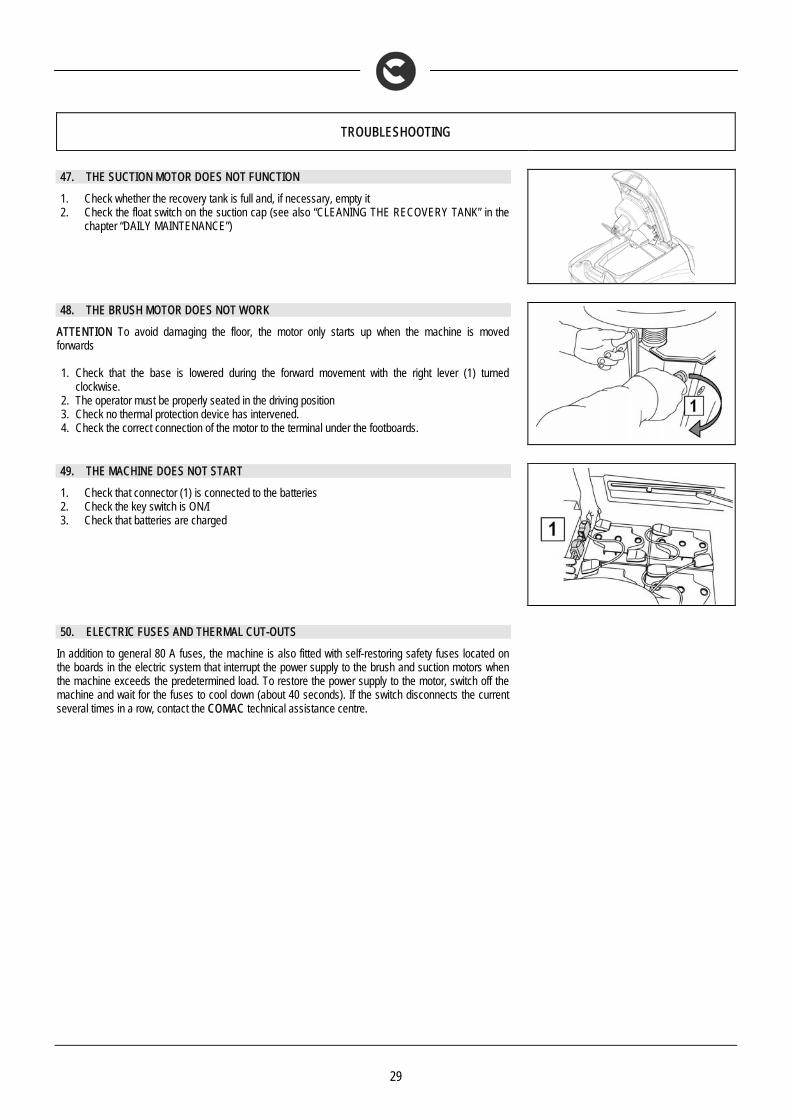
47. THE SUCTION MOTOR DOES NOT FUNCTION
1. Check whether the recovery tank is full and, if necessary, empty it 2. Check the float switch on the suction cap (see also “CLEANING THE RECOVERY TANK” in the
chapter “DAILY MAINTENANCE”)
48. THE BRUSH MOTOR DOES NOT WORK
ATTENTION To avoid damaging the floor, the motor only starts up when the machine is moved forwards 1. Check that the base is lowered during the forward movement with the right lever (1) turned
clockwise. 2. The operator must be properly seated in the driving position 3. Check no thermal protection device has intervened. 4. Check the correct connection of the motor to the terminal under the footboards.
49. THE MACHINE DOES NOT START
1. Check that connector (1) is connected to the batteries 2. Check the key switch is ON/I 3. Check that batteries are charged
50. ELECTRIC FUSES AND THERMAL CUT-OUTS
In addition to general 80 A fuses, the machine is also fitted with self-restoring safety fuses located on the boards in the electric system that interrupt the power supply to the brush and suction motors when the machine exceeds the predetermined load. To restore the power supply to the motor, switch off the machine and wait for the fuses to cool down (about 40 seconds). If the switch disconnects the current several times in a row, contact the COMAC technical assistance centre.
30
DISPOSAL
To dispose of the machine, take it to a demolition centre or an authorised collection centre. Before scrapping the machine it is necessary to remove and separate the following materials and send them to the appropriate collection centres in accordance with the environmental hygiene regulations currently in force:
• brushes • felt • electric and electronic parts* • batteries • plastic parts (tanks and handlebars) • metal parts (levers and frame)
(*) In particular, to scrap the electric and electronic parts, contact your area distributor.

31
CHOOSING AND USING THE BRUSHES
POLYPROPYLENE BRUSH (PPL) Used on all types of floors. Good resistance to wear and tear, and hot water (no greater than 60°C). The Polypropylene brush is non-hygroscopic and therefore retains its characteristics even when working in wet conditions. NYLON BRUSH Used on all types of floors. Excellent resistance to wear and tear, and hot water (even over 60°C). The nylon is hygroscopic and so tends to lose its characteristics over time when working in wet conditions. ABRASIVE BRUSH The bristles of this type of brush are charged with highly aggressive abrasives. It is used to clean very dirty floors. To avoid floor damage, work only with the pressure strictly necessary. THICKNESS OF THE BRISTLES Thicker bristles are more rigid and are therefore used on smooth floors or floors with small joints. On uneven floors or those with deep joints, it is advisable to use softer bristles which can enter the gaps more easily. Remember that when the bristles are worn and therefore too short, they will become rigid and are no longer able to penetrate and clean deep down. In this case, like with over-large bristles, the brush tends to jump. PAD HOLDER The pad holder is recommended for cleaning shiny surfaces. There are two types of pad holder: 1. The traditional pad holder is fitted with a series of anchor points that allow the abrasive floor pad to be held and dragged while working. 2. The CENTRE LOCK type pad holder not only has anchor points, but also a snap-type central locking system in plastic that allows the abrasive floor
pad to be perfectly centred and held without any risk of it becoming detached. This type of holder is especially suitable for machines with several brushes, where the centring of the abrasive floor pads is difficult.
TABLE FOR CHOOSING THE BRUSHES
Machine No. of brushes Code Type of bristles ∅ Bristles ∅ Brush Length Notes
INNOVA 65 2
422189 422971 422972 422981 422973
PPL PPL PPL
TYNEX (ABRASIVE) PAD HOLDER
0.3 0.6 0.9
340 340 340 340 330
CENTER LOCK
INNOVA 75 2
427715 427716 427717 427719 427718
PPL PPL PPL
TYNEX (ABRASIVE) PAD HOLDER
0.3 0.6 0.9
390 390 390 390 380
CENTER LOCK
INNOVA 85 2
430696 430697 430698 430699 431122
PPL PPL PPL
TYNEX (ABRASIVE) PAD HOLDER
0.3 0.6 0.9
430 430 430 430 410
CENTER LOCK
INNOVA 100 2
436310 436311 436312 436314 436315
PPL PPL PPL
TYNEX (ABRASIVE) PAD HOLDER
0.3 0.6 0.9
510 510 510 510 500
CENTRE LOCK

32
EC DECLARATION OF CONFORMITY
The undersigned manufacturer:
COMAC S.p.A. Via Maestri del Lavoro, 13
37059 Santa Maria di Zevio (VR) declares under its sole responsibility that the product
SCRUBBING MACHINES
mod. INNOVA 65B M 2011 - INNOVA 75B M 2011 - INNOVA 85B M 2011 - INNOVA 100B M 2011
complies with the requirements of the following Directives:
• 2006/42/EC: Machinery Directive. • 2006/95/EC: Low Voltage Directive. • 2004/108/EC: Electromagnetic Compatibility Directive.
They also comply with the following standards: • EN 60335-1: Household and similar electrical appliances - Safety. Part 1: General regulations. • EN 60335-2-72: Household and similar electrical appliances. Part 2: Generic standards for automatic machines for floor treatment for commercial and
industrial use. • EN 60335-2-29: Household and similar electrical appliances. Part 2: Special standards for battery chargers. • EN 12100-1: Machine safety - Fundamental concepts, fundamental principles of design - Part 1: Basic terminology and methodology. • EN 12100-2: Machine safety - Fundamental concepts, fundamental principles of design - Part 2: Technical principles. • EN 61000-6-2: Electromagnetic compatibility (EMC) - Part 6-2: Generic standards – Immunity for industrial environments. • EN 61000-6-3: Electromagnetic compatibility (EMC) - Part 6-3: Generic standards — Standard emission for residential, commercial and light-industrial
environments. • EN 61000-3-2: Electromagnetic compatibility (EMC) - Part 3-2: Limits – Limits for harmonic current emissions (Equipment with input current ≤ 16 A per
phase). • EN 61000-3-3: Electromagnetic compatibility (EMC) - Part 3-3: Limits – Restriction of voltage variations and flicker in low voltage power supply systems
for devices with a rated current ≤ 16 A. • EN 55014-1: Electromagnetic compatibility - Regulations for household appliances, electrical devices and similar equipment. Part 1: Emission -
Regulation for product family. • EN 55014-2: Electromagnetic compatibility - Regulations for household appliances, electrical devices and similar equipment. Part 2: Immunity -
Regulation for product family. • EN 62233: Household and similar electrical appliances - Electromagnetic fields Methods for evaluation and measurement.
The person authorised to compile the technical file:
Sig. Giancarlo Ruffo Via Maestri del Lavoro, 13 37059 Santa Maria di Zevio (VR) - ITALY Santa Maria di Zevio (VR), 23/10/2012
COMAC S.p.A. Legal representative
Giancarlo Ruffo
COMAC spa
Via Maestri del Lavoro, 13 – 37059 Santa Maria di Zevio – Verona – ITALY Tel. +39 045 8774222 – Fax +39 045 8750303 - E-mail: [email protected] o [email protected] - www.comac.it