use case diagrams - ii.pwr.edu.pl · use cases •use case diagrams describe what a system does...
TRANSCRIPT

Use Case Diagrams

Use Cases
• What is a Use Case
A formal way of representing how a
business system interacts with its
environment
Illustrates the activities that are performed
by the users of the system
A scenario-based technique in the UML
A sequence of actions a system performs that
yields a valuable result for a particular actor.

Use Case Analysis
• What is an Actor?
– A user or outside system that interacts
with the system being designed in order
to obtain some value from that interaction
• Use Cases describe scenarios that describe
the interaction between users of the system
(the actor) and the system itself.

Use Cases
• Use case diagrams describe what a
system does from the standpoint of an
external observer. The emphasis is on
what a system does rather than how.
• Use case diagrams are closely
connected to scenarios. A scenario is
an example of what happens when
someone interacts with the system.

Use Cases
• Here is a scenario for a medical clinic.
• A patient calls the clinic to make an appointment for a yearly checkup. The receptionist finds the nearest empty time slot in the appointment book and schedules the appointment for that time slot. "
• We want to write a use case for this scenario.
• Remember: A use case is a summary of scenarios for a single task or goal.

Use Cases
• Step 1 Identify the actors
• As we read the scenario, define those
people or systems that are going to
interact with the scenario.
• A patient calls the clinic to make an appointment for a yearly checkup.
The receptionist finds the nearest empty time slot in the appointment
book and schedules the appointment for that time slot. "

Actors
• An Actor is outside or external the system.
• It can be a:
– Human
– Peripheral device (hardware)
– External system or subsystem
– Time or time-based event
• Represented by stick figure
Use Cases
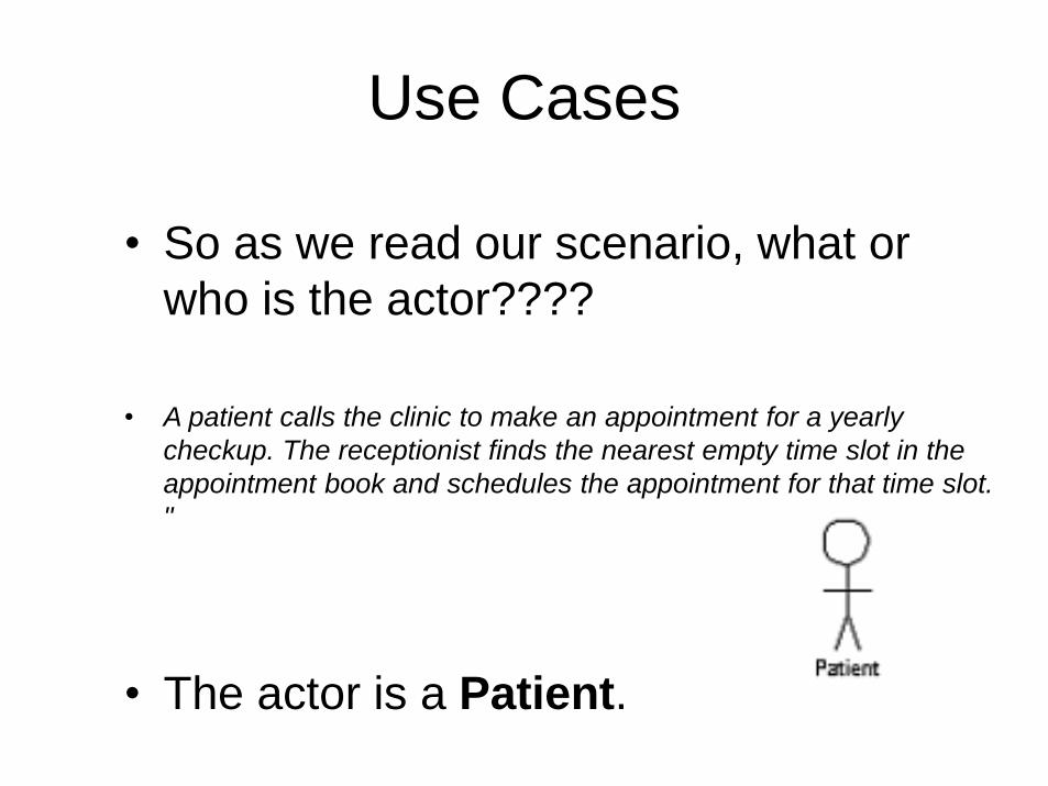
• So as we read our scenario, what or
who is the actor????
• A patient calls the clinic to make an appointment for a yearly
checkup. The receptionist finds the nearest empty time slot in the
appointment book and schedules the appointment for that time slot.
"
• The actor is a Patient.

Use Cases
• The use case is a summary of
scenarios for a single task or goal.
• So What is the Use Case????
• The Use Case is Make Appointment.
• It is a use case for the medical clinic.

Use Cases
• The picture below is a Make Appointment use case for the medical
clinic.
• The actor is a Patient. The connection between actor and use case
is a communication association (or communication for short).
Actors are stick figures. Use cases are ovals. Communications are lines that link actors to use cases.Actors are stick figures. Use cases are ovals. Communications are
lines that link actors to use cases.

Use Case Components
• The use case has three components.
• The use case task referred to as the use case
that represents a feature needed in a software
system.
• The actor(s) who trigger the use case to activate.
• The communication line to show how the actors
communicate with the use case.

Use Case Diagram - Use Case
• A major process performed by the system
that benefits an actor(s) in some way
• Models a dialogue between an actor and
the system
• Represents the functionality provided by
the system

Use Case
• Each use case in a use case diagram
describes one and only one function in
which users interact with the system
– May contain several “paths” that a user can
take while interacting with the system
– Each path is referred to as a scenario

Use Case
• Labelled using a descriptive verb-noun
phrase
• Represented by an oval
Make
Appointment

Use Case - Actor
• Labelled using a descriptive noun or
phrase
• Represented by a stick character

Use Case - Relationships
• Relationships
– Represent communication between actor and
use case
– Depicted by line or double-headed arrow line
– Also called association relationship
Make
Appointment

Use Case - Relationships
• Boundary
– A boundary rectangle is placed around the
perimeter of the system to show how the actors
communicate with the system.
Make
Appointment

Use-Case Diagram
A use case diagram is a collection of actors, use cases, and their
communications.

Use Case Diagram
• Other Types of Relationships for Use
Cases
– Generalization
– Include
– Extend

Components of Use Case Diagram
• Generalization Relationship
– Represented by a line and a hollow arrow• From child to parent
Child use case Parent use case
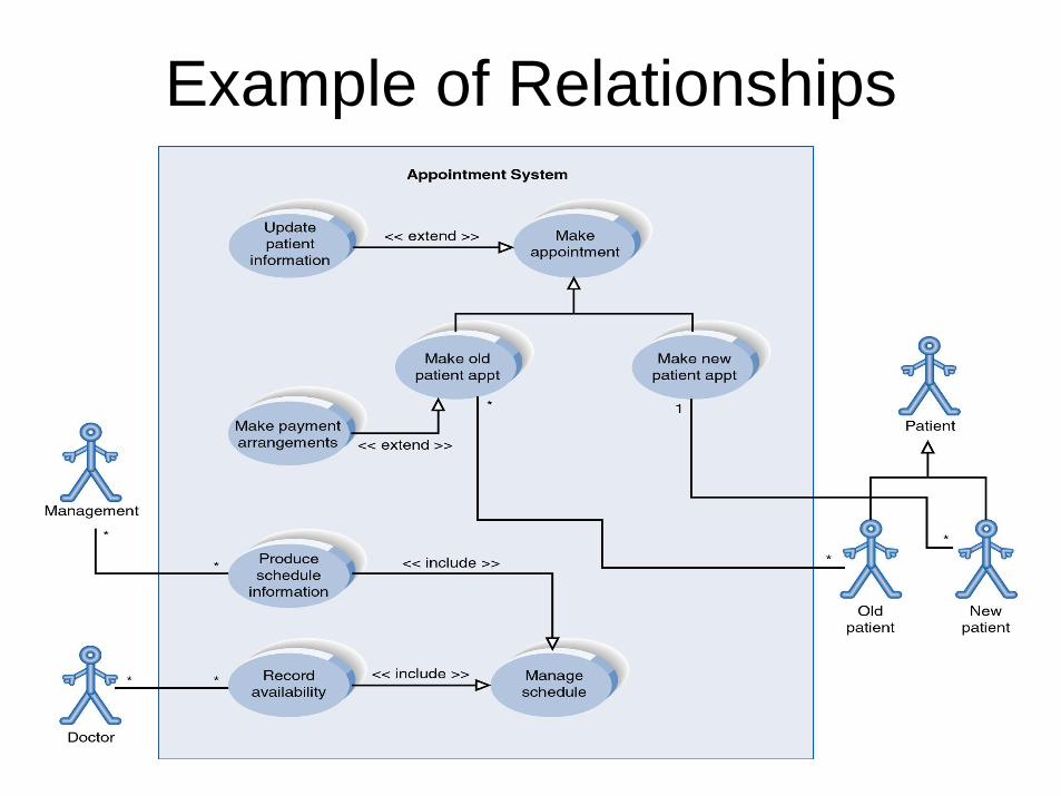
Example of Relationships

Use Case Diagram
• Include Relationship
– Represents the inclusion of the functionality of
one use case within another
– Arrow is drawn from the base use case to the
used use case
– Write << include >> above arrowhead line

Use Case Diagram
• Extend relationship
– Represents the extension of the use case to
include optional functionality
– Arrow is drawn from the extension use case
to the base use case
– Write << extend >> above arrowhead line

Example of Relationships

Use Case Relationships
• Pro:
– Reduces redundancy in use cases
– Reduces complexity within a use case
• Con
– May introduce complexity to use case
diagram