use condition based reliability evaluation: an example ... method, summarizing advantages,...
TRANSCRIPT

Use Condition Based Reliability Evaluation: An ExampleApplied to Ball Grid Array (BGA) Packages
SEMATECHTechnology Transfer # 99083813A-XFR

© 1999 SEMATECH, Inc.
SEMATECH and the SEMATECH logo are registered service marks of SEMATECH, Inc.International SEMATECH and the International SEMATECH logo are registered service marks
of International SEMATECH, Inc., a wholly-owned subsidiary of SEMATECH, Inc.
Product names and company names used in this publication are for identification purposes only and may be trademarks or service marks of their respective companies

Use Condition Based Reliability Evaluation: An Example Applied toBall Grid Array (BGA) Packages
Technology Transfer # 99083813A-XFRSEMATECH
August 31, 1999
Abstract: Increased package performance expectations, new packaging materials, and market segmentationare key trends in today’s semiconductor industry. The SEMATECH Reliability TechnologyAdvisory Board has developed a reliability test methodology to keep pace with these markettrends. Based on that methodology, the SEMATECH Qualification, Monitors and Controls Teamhas produced this paper, which provides an example of how to apply the method to ball grid array(BGA) packages. An example of the use conditions qualification methodology is presented indetail. The methodology is briefly defined and input requirements are listed. Accelerated testconditions are developed, based on knowledge of the customers’ use conditions, activationenergies, and failure models. Test conditions that produce statistically justifiable failurepopulations that are not likely to occur in the defined use environments are minimized oreliminated. Examples of legacy test conditions from several companies are provided forcomparison.
Keywords: Ball Grid Array Package, Customer Satisfaction, Reliability Testing
Authors: Joe Veshinfsky, Lucent; Bob Purvee, IBM; Robin Susko, IBM; Jack McCullen, Intel; NoelDurrant, SEMATECH
Approvals:Noel Durrant, Author
Bob Werner, Director, Advanced TechnologyDan McGowan, Technical Information Transfer Team Leader


Page 1 of 22Use Conditions Based Reliability Evaluation – An Example Applied to BGA Packages
SEMATECH Technology Transfer #99083813A-XFR
SEMATECHQualification, Monitors and Controls Team
Use Conditions Based Reliability Evaluation –An Example Applied to BGA Packages
WHITE PAPERMay 1999
Qualification, Monitors and Controls Team Members
Advanced Micro DevicesJim HooperRanjit Gannamani
ConexantJohn Tsutsui
Hewlett PackardSheila Davis
IBMBob Purvee *
Robin Susko *Intel
Jack McCullen *
LucentJoe Veshinfsky *
MotorolaNick Lycoudes
TIColin MartinCharles Baker
* primary contributors

Page 2 of 22Use Conditions Based Reliability Evaluation – An Example Applied to BGA Packages
SEMATECH Technology Transfer #99083813A-XFR
EXECUTIVE SUMMARYIncreased package performance expectations, new packaging materials and marketsegmentation are key trends in today’s semiconductor industry. The SEMATECH ReliabilityTechnology Advisory Board has developed a reliability test methodology to keep pace with thesemarket trends. The Use Condition methodology provides for selecting stress conditions based onknowledge of the components usage environment. Based on that methodology, the SEMATECHQualification, Monitors and Controls Team has produced this paper which is an example of howto apply the method to BGA packages. Compared to stress-based methods, this approachrequires more knowledge about the physics of failure mechanisms and about the anticipated useof the component.

Page 3 of 22Use Conditions Based Reliability Evaluation – An Example Applied to BGA Packages
SEMATECH Technology Transfer #99083813A-XFR
ABSTRACT
An example of the Use Conditions Qualification methodology is developed and presented indetail. The methodology is briefly defined and input requirements are listed. Accelerated testconditions are developed based on knowledge of the customers’ use conditions, activationenergies and failure models. Test conditions that produce statistically justifiable failurepopulations that are not likely to occur in the defined use environments are minimized oreliminated. Examples of legacy test conditions from several companies are provided forcomparison.
1. INTRODUCTION
Through a detailed comparison of qualification practices, it was determined that companies areusing different procedures and tests to qualify similar package technologies. Packagesubcontractors, IC manufacturers and the final customer will sometimes perform their ownqualification on a new package technology delaying the introduction of this package into finaluse. It was determined that there was a need to come up with a uniform qualificationmethodology that could be used with these new package technologies.
In trying to come up with a uniform set of qualification tests/requirements, it was determined thatthe use conditions of the package would be very important in determining the qualification teststhat should be performed. There is such a wide range of possible use conditions that theapproach of trying to establish even a minimum set of qualification requirements that wouldapply to all applications was abandoned. It was decided that a better way to handle this problemwould be to determine a methodology that would establish the qualification testing that is basedon the actual use conditions of the package
The purpose of this paper is therefore to serve as an example of using the RTAB “Use ConditionBased Reliability Evaluation of New Semiconductor Technologies” methodology to determine theuse conditions for BGA packages and then to establish the stress requirements necessary toqualify the package for the intended use. This paper will serve only as an example of how thismethodology should be performed. It is not intended to be considered as a specification. Everycompany that desires to use this methodology will have to determine the failure mechanisms,activation energies and other information that is specific to their own package.
Each company that makes use of this methodology will also have to determine whether toperform the necessary testing using test chips and/or actual product. For the purpose of thisexample paper, the demonstrated procedures would be the same if either test chips or actualproduct were used.
2. DESCRIPTION OF RTAB METHODOLOGY
This section is a brief description of the RTAB Use Conditions Methodology.
A. Definition of Environmental, Lifetime and Manufacturing Conditions
Define the environmental, lifetime and manufacturing conditions the package will be exposed to.The criteria that need to be considered for the intended application include:
• the expected operating lifetime of the package• the actual number of weekly operating hours• the number of environmental and power cycles experienced per day• the relative humidity and temperature of the operating environment• the overall storage temperature• the cumulative end of life failure rate

Page 4 of 22Use Conditions Based Reliability Evaluation – An Example Applied to BGA Packages
SEMATECH Technology Transfer #99083813A-XFR
B. Determination of Exploratory Reliability Stresses Determine an initial set of reliability stresses to be used for collecting data on failuremechanisms. These stresses must be chosen so as not to exceed the physical capability of anyof the materials used in the package. It is assumed that the use conditions are within the physicalcapability of the package material set. A list of commonly used stresses is included in the RTABdocument. It is necessary to determine if there is anything unique about the package that mayrequire new or modified stress tests. It is also necessary to determine: • the appropriate models to be used• possible failure mechanisms• acceleration factors for each failure mechanism
All of the above factors can then be combined to determine the initial set of stresses. As noted inthe RTAB paper, a number of these factors may be known based on historical data.
As in the RTAB paper, this step should be divided into a number of interrelated activities. Forthis paper these activities have been applied to BGA packages and will be discussed in detail inSection 5.
C. Determine Extended Stress Conditions
Define extended stress conditions based on the estimated acceleration factors. The purpose ofthe extended stress conditions is to help define the margin of the technology, identify all of thepossible failure mechanisms and to determine the actual acceleration factors.
D. Apply Data to Models
Perform testing using the initial and extended stress qualification conditions. The actual testresults can then be compared to the results predicted by the models to determine if thetechnology follows the model or follows a new acceleration curve. Acceleration factors may haveto be recalculated at this point.
E. Determine Final Reliability Stress Conditions
The next step is to use the acceleration factors determined above to come up with a final set ofqualification stress conditions and duration. It is important to look for and discount irrelevantfailure mechanisms.
F. Establish Baseline Performance
Establish a baseline performance for the material set or process that is being qualified.
3. COMPARISON OF QUALIFICATION METHODOLOGIES
The following chart briefly compares the traditional, “Legacy”, qualification method and “UseCondition” method, summarizing advantages, disadvantages and information required.

Page 5 of 22Use Conditions Based Reliability Evaluation – An Example Applied to BGA Packages
SEMATECH Technology Transfer #99083813A-XFR
Comparison of Benefits and Data Requirements “Legacy” vs. “Use Condition”Qualification Methodologies
Legacy (Traditional) Based Qualification “Use Condition” based Qualification• Certification requirements based on
standard stresses• Stress technology is fixed and doesn’t
easily accommodate new requirements• Reviews are done only in response to
extremely significant changes• New technologies must meet requirements
far beyond their useful life.• Advantage:
simplicity in collecting and reporting data• Disadvantage:
Limited understanding of packageperformanceLimited knowledge of application failurerates
• Internal Supplier Data Requirements:Attribute data at end points of requiredstresses
• Certification requirements based onproduct lifetime
• Stress technology scales to match theoperating requirement environment of thetechnology
• Automatic review cycle of methods,testing, environment every generation
• Allows for optimization of materials andprocesses for reduced cost
• Advantage:More accurate prediction of lifetimeperformance and margins
• Disadvantage:More complex approach for collecting andreporting data
• Internal Supplier Data Requirements:Use conditions and lifetime requirementsAppropriate attribute and variables dataPackage materials propertiesFailure mechanisms associated with eachstressAcceleration factors and models for eachfailure mechanism
4. DATA APPLICATION TO DERIVE ACTIVATION ENERGIES AND FAILURE MECHANISMMETHODOLOGY
Definition of Environmental, Lifetime and Manufacturing Conditions
For the purposes of this example white paper the following set of use conditions were selected.These values were selected to illustrate the methodology and are based on a combination ofsurvey data, member company inputs, and judgments by the authors. It will be necessary foreach company following this procedure to determine their own use conditions at this step. Thedata in this and subsequent steps is included only to serve as an example.
Assumptions:• Operating life: 7 years (62,000 hours = 7 years)• Power on (hours per week): 168 hours(62,000 hours)• Power cycles per day: 3 (7500 cycles = 3 X 365 X 7)• Environmental (ambient temperature) cycles per day: 1 (3000 cycles = 1 X 365 X 7)• Moisture: 30°C and 85% relative humidity• Operating temperature range of ambient: 5°C – 45°C (∆T = 40°C)• Storage temperature: -40°C to 55°C• Maximum junction temperature (Tjmax): 100°C• Manufacturing conditions/considerations: surface mount by convection reflow; JEDEC
preconditioning; not exposed to full immersion solder wave

Page 6 of 22Use Conditions Based Reliability Evaluation – An Example Applied to BGA Packages
SEMATECH Technology Transfer #99083813A-XFR
5. DETERMINATION OF EXPLORATORY RELIABILITY STRESSES The SEMATECH QMC Committee discussed the potential failure mechanisms typically relatedto BGA packages. As in the RTAB white paper procedure, the QMC group of expertsestablished the list of reliability concerns for the new BGA package. The following is thecomprehensive list of failure mechanisms thought possible for the full range of BGA packagetypes currently available. i. Thermal Mechanical Failure Mechanisms: CTE Mismatch Device to Package • Flip Chip(Bumped)/Joint Fatigue of unencapsulated and encapsulated joints• Flip Chip/Joint Fatigue if delamination of underfill occurs• Wire Bond Device to Die Attach Adhesive CTE Mismatch Module to PWB • BGA Solder Joint Fatigue CTE Mismatch Encapsulant to Device • Underfill to Flip Chip Joints• Overmold/glob top to ILB (Inner Lead Bond)/OLB (Outer Lead Bond)• Overmold/Glob top to Wire Bonds Delamination and Loss of Adhesion at Interfaces • Device to Underfill• Underfill to Substrate• Solder mask to Substrate• Cap/Stiffener to Adhesive• Overmold or Glob to Device• Overmold or Glob to Substrate/Tape• Heat Sink to Cap to Stiffener Interfaces• Pad adhesion to Substrate Solder Creep Rupture • Assembled Module with Large Heat Sink with time and gravity Metal Circuit Fatigue • Substrate Circuit Lines• Inner Lead Bond(ILB)/Outer Lead Bond(OLB)• Substrate PTHs (Plated Thru Holes)/Thru Vias Assembly Induced Problems • Initial Reflow• Rework - BGA Joint Defects, Cu dissolution of pads/circuitry

Page 7 of 22Use Conditions Based Reliability Evaluation – An Example Applied to BGA Packages
SEMATECH Technology Transfer #99083813A-XFR
Defect Failures • Wire bond Defects (wire nicks, bond foot, etc.)• Non-uniform joints (higher temperature flip chip joints)• Non-uniform balls (eutectic solder on BGAs)• Circuit Lines (neckdowns, mouse bites)• PTHs (plating uniformity within hole and on the surface)• ILB/OLB Defects (nicks, etc.) Device Cracking • Defects• CTE Mismatch Passivation/Thin Film Cracking • Interaction of Device Passivation and Overmold/Encapsulant ii. Temperature/Humidity (with and without bias) Failure Mechanisms: Corrosion • Oxidation• Contamination Metal Migration • Dendrite Growth• Corrosion Product Growth• Metal Depletion into Solution Oxidation • Oxide Film Growth Delamination of Material Interface • Loss of Interfacial Adhesion iii. Thermal Aging Failure Mechanisms: Material Breakdown • Material Oxidation• Electrical Degradation• Thermal Degradation• Intermetallic Degradation

Page 8 of 22Use Conditions Based Reliability Evaluation – An Example Applied to BGA Packages
SEMATECH Technology Transfer #99083813A-XFR
PROCEDURE: A. Bound Reliability Stress Conditions Based on Package Material Properties and
Capabilities: Stress conditions must be selected such that the testing does not produce false failuremechanisms that are artifacts of the test conditions and not representative of the product’s useenvironment. For the BGA packages the areas of stress typically used are thermal cycle,temperature/humidity with and without bias and thermal aging. The areas of concern for eachstress type are discussed below. i. Selection of Thermal Cycle Test Conditions Thermal cycle test conditions, in particular, must be selected with care. The selection of thethermal cycle range and duration for product test should be based on use environment, the life ofthe product and the material capabilities. In either development or qualification, several thermal cycle conditions can be performed on theBGA product. Ideally parts should be stressed to a preselected failure percentage. Failuremechanisms should be compared between thermal cycle conditions. It is critical that all failuremechanisms encountered be judged against use conditions for the intended product. Failuresthat are observed at the most severe conditions may not represent a field concern for thatapplication and are merely an artifact of the severe test conditions. Areas of concerns generatedby extreme thermal cycling include exceeding the material’s glass transition at high temperature,moisture absorption by the BGA substrate and material ductility at low temperatures. It shouldbe noted that PBGA and TBGA packages, with the organic materials used in these BGAsubstrates, are more sensitive to some aspects of thermal cycling than CBGA packages.Exceeding the glass transition temperature (Tg) of a material changes the coefficient of thermalexpansion as well as the properties of the given material. Exceeding the ductility of materialscan generate unrealistic failures due to brittleness and crack propagation at the lowertemperature exposures. ii. Selection of Temperature/Humidity (with and without bias) Stress Conditions The selection of Temperature and Humidity test conditions must be done with care. Tests suchas HAST, autoclave and 85°C/85%RH testing, while being useful development tools, must beused with caution since the stress conditions selected and the duration of the test can causedegradation of package materials which will lead to unrealistic failure of the package with respectto the application environment. It is advisable, when performing T&H testing, that one be able tobridge back to a known T&H condition where the failure mechanisms are known and relate to thefield exposure expected for the specific application.
• Excessive package delamination inconsistent with field application conditions.• Excessive corrosion and metal migration inconsistent with field environment.• Temperature and humidity effects which one will simply not see in the field application. It is
possible that the field application may result in the module operating in a “dry environment”which is being over accelerated by the THB stress conditions.
iii. Selection of Thermal Aging Stress Conditions The cautions related to this stress condition are exceeding the material Tg and material interfaceadhesion. Extended exposure of organic BGA packages to high temperatures result in oxidationand breakdown of the organic materials and can adversely affect mechanical and electricalperformance of the package.
Page 9 of 22Use Conditions Based Reliability Evaluation – An Example Applied to BGA Packages
SEMATECH Technology Transfer #99083813A-XFR
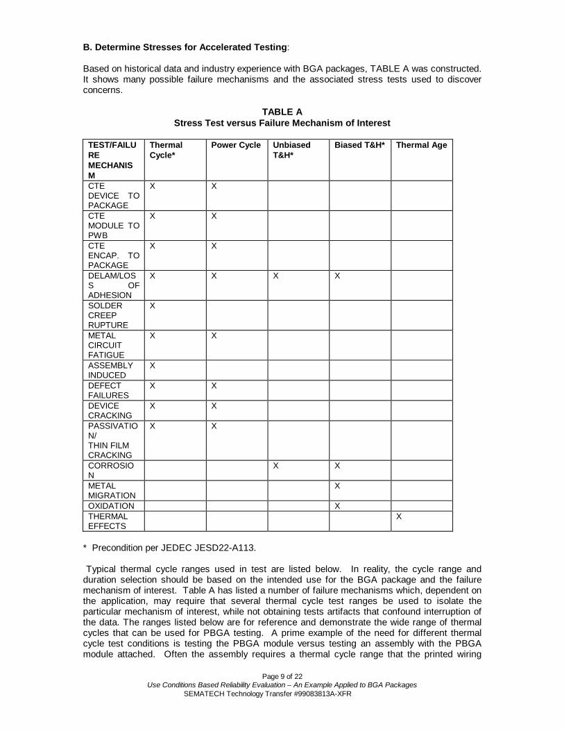
B. Determine Stresses for Accelerated Testing: Based on historical data and industry experience with BGA packages, TABLE A was constructed.It shows many possible failure mechanisms and the associated stress tests used to discoverconcerns.
TABLE AStress Test versus Failure Mechanism of Interest
TEST/FAILUREMECHANISM
ThermalCycle*
Power Cycle UnbiasedT&H*
Biased T&H* Thermal Age
CTEDEVICE TOPACKAGE
X X
CTEMODULE TOPWB
X X
CTEENCAP. TOPACKAGE
X X
DELAM/LOSS OFADHESION
X X X X
SOLDERCREEPRUPTURE
X
METALCIRCUITFATIGUE
X X
ASSEMBLYINDUCED
X
DEFECTFAILURES
X X
DEVICECRACKING
X X
PASSIVATION/THIN FILMCRACKING
X X
CORROSION
X X
METALMIGRATION
X
OXIDATION XTHERMALEFFECTS
X
* Precondition per JEDEC JESD22-A113.
Typical thermal cycle ranges used in test are listed below. In reality, the cycle range andduration selection should be based on the intended use for the BGA package and the failuremechanism of interest. Table A has listed a number of failure mechanisms which, dependent onthe application, may require that several thermal cycle test ranges be used to isolate theparticular mechanism of interest, while not obtaining tests artifacts that confound interruption ofthe data. The ranges listed below are for reference and demonstrate the wide range of thermalcycles that can be used for PBGA testing. A prime example of the need for different thermalcycle test conditions is testing the PBGA module versus testing an assembly with the PBGAmodule attached. Often the assembly requires a thermal cycle range that the printed wiring

Page 10 of 22Use Conditions Based Reliability Evaluation – An Example Applied to BGA Packages
SEMATECH Technology Transfer #99083813A-XFR
board portion of the assembly can withstand. If too severe a range is selected, the plated thruholes can crack impeding ones ability to test fatigue of the BGA solder joints. • 0°C to 100°C• 0°C to 125°C• -40°C to 65°C• -40°C to 115°C• -40°C to 125°C• -40°C to 150°C• -55°C to 125°C• -65°C to 150°C
Other stress tests, such as High Temperature Operational Life (HTOL), while being useful fordetermining semiconductor failure susceptibility, have not been found to drive any unique failuremechanisms in BGA packages. It is important to look at the failure mechanisms of interest in theBGA package being tested and decide what stress test methodology is best suited fordiscovering package failure potential.
C. Determine Unique Requirements:
For the PBGA package of interest, most requirements are standard. Unique requirements wouldbe those associated with the assembly of that package to a Printed Wiring Board (PWB). ThePWB properties (such as CTE and stiffness), SMT assembly parameters and application layoutall can play a role in the reliability performance of the BGA package.
D. Develop or Determine Stress Models for BGA Package:
i. Mechanisms That Have Known Models
Model development includes both stress test based and computer generated information. Inparticular, finite element modeling, when fine-tuned with stress test data, is very good atidentifying regions of high stress for the BGA package. Such models are especially useful foruse in follow-on technologies where the database has already been verified with stress testresults.
From experience on PBGA packages, it has been shown that flip chip and BGA solder joints,assuming that they are eutectic or 90/10 solder, follow the Modified Coffin-Manson equationdescribed in the next section of this paper. It is important that the thermal cycle regime usedemploys slow cycling, on the order of 1.7 to 3 cycles per hour (typically 2 cycles per hour) and adwell of 4 to 5 minutes around the peak temperature. Often a single zone chamber is preferredto maintain the slower ramp rates. The dwell is needed to allow the solder joints to creep. Lackof dwell prevents the normal solder creep and allows the package to perform better in test thanin actual use. In order to test the BGA joint integrity, assembly to a PWB is needed. Whereapplicable, this assembly should simulate the end use with respect to component layout andPWB cross section, in particular. Power cycling has also been established as a method to testBGA integrity. Solder creep rupture requires similar stress conditions. The package requiresassembly to a PWB and the attachment of a heat sink. Testing should be performed with thepart situated, as it would be in the field.
Modeling and experience have shown that substrate metal circuit fatigue is not susceptible tocycle frequency. However, the type of thermal cycling chosen should be based on the failuremechanism of interest. Wet Thermal Shock is typically used to identify embrittlement andmaterial defect concerns while standard temperature cycling is used to detect low cycle fatigueconcerns.

Page 11 of 22Use Conditions Based Reliability Evaluation – An Example Applied to BGA Packages
SEMATECH Technology Transfer #99083813A-XFR
Device defects, such as chip cracking, can be discovered with only a few cycles of thermalcycling. This is because the device is brittle and only a few cycles are needed to activate andextend the crack.
ii. Mechanisms That do not Have Known Models
The following paragraphs cover what can be done for the case of failure mechanisms that do nothave known models to describe them.
Passivation/Thin Film Cracking is not typically a BGA package concern. If there is reason tohave this concern, it can be identified at low temperature and is the result of adverse interactionbetween the device passivation and it’s over mold/encapsulant.
Delamination is usually moisture driven where temperature and humidity testing is used todiscover problems. However, there are cases where it is driven by thermal cycling instead.Straight thermal cycle testing, including JEDEC preconditioning of choice, is adequate toobserve this delamination.
The failure mechanisms of interest in temperature and humidity stress are primarily related tomaterial degradation. They fall into three major areas; corrosion, metal migration anddelamination of material interfaces.
Corrosion mechanisms fall into two major categories: galvanic and electrolytic acceleratedmechanisms. Both can be accelerated by temperature and high relative humidity. Both can beobserved under field application conditions.
The metal migration mechanism involves the physical movement of metal atoms from theiroriginal location to another, deleterious position. This mechanism involves dissolution and/ortransport of metal ions, i.e. dendritic growth, corrosion product growth on the metal or metaldepletion into solution with no subsequent deposition on the structure of interest.
Oxidation is defined as the classical mechanism where the electronic state of the metal ischanged. The oxidation normally involves growth of an oxide film, which will affectelectronic/thermal conduction of the metal film.
Delamination of material interfaces has a critical RH level which will cause water molecules tointerfere with material interface bonding, i.e. hydrogen bonding.
T&H stress conditions (with and without bias) of 85°C/85RH are recommended for determinationof new failure mechanisms. However, one can proceed with accelerated T&H testing, such asHAST, for the first verification test. If new or unexplained failure mechanisms arise during thattest sequence, a validation of the failure mechanism should be performed. One possible methodfor doing this would be using a T&H test condition for which an extensive database alreadyexists, typically 85°C/85% RH. This test condition has several attributes that make it veryattractive for new package and material evaluations. The temperature is comfortably below theTg of most organic packaging material and the humidity is above the 70% threshold (determinedseveral years ago by empirical data). These conditions seem to activate corrosion and oxidationmechanisms in the T&H environment through the formation of a thin film of moisture on thesample’s surface.
From a BGA package evaluation perspective, use of either high or low temperature storagetesting has to be based on application requirements. Typically low temperature storage is usedwhen the application is intended to survive long periods at low temperatures. Conversely hightemperature storage is used for simulation of burn-in effects, extended operation at elevatedtemperatures (under auto hood applications) or for accelerating the effects of extended storageat elevated temperature.

Page 12 of 22Use Conditions Based Reliability Evaluation – An Example Applied to BGA Packages
SEMATECH Technology Transfer #99083813A-XFR
E. Technology Failure Mechanisms and Known Acceleration Models:
Based on the expert input obtained from the QMC group and our present base knowledge offailure mechanisms and acceleration factors, the following acceleration models were deemedapplicable to the PBGA package in question. Reference RTAB Paper on Acceleration Factors,Models & Reliability Statistics and EIA/JEP122 “Failure Mechanisms and Models for SiliconSemiconductor Devices”
i. Thermal Cycle Failure Mechanisms
The Model suggested in the RTAB Paper is the Coffin-Manson model:
Nf = C0 * (∆T)n
The Acceleration factor (AF) is:
Where:Nf = Number of cycles to failure,C0 = a material dependent constant,∆T = entire temperature cycle-range for the device,n = an empirically determined constant.
The acceleration factor (AF) is the ratio of Nf(use)/Nf(stress).
For Substrate Metal Fatigue the exponent of 2 is typically utilized based upon historicaldatabases.
For passivation/thin film cracking the same equation is used as for metal circuit line fatigue,but the exponent utilized is typically 4.0, but can range from 2 to 11 based on the devicepassivation used. It should be noted that passivation/thin film cracking on the device is not atypical failure mechanism driven by the BGA package.
With respect to thermal cycle induce delamination there is no known acceleration model.
The Coffin-Manson Model was modified by Landzberg and Norris (1969) to the form:
Where:Nf = Number of cycles to a given percent failureA0 = Material dependent constantf = Cycling frequency∆T = Temperature rangeG = Arrhenius factor that depends on maximum temperature reached in a cycle (Tmax)n = An empirically determined constantβ = 1/3
( )max
n
0f TGT1fAN ∗
∆
∗∗= β
n
use
stress
TTAF
∆∆=

Page 13 of 22Use Conditions Based Reliability Evaluation – An Example Applied to BGA Packages
SEMATECH Technology Transfer #99083813A-XFR
Historical data has demonstrated that we can determine the thermal cycle acceleration (AF) ofsolder joint failures in the BGA package, using the Landzberg and Norris equation above andtaking the ratio of Nf(use)/Nf(stress).
The strain component is 1.9 for either eutectic or 90/10 solder.
The exponent for frequency is 1/3 and we assume F(use) is 6. F(stress) is usually 48 whichequates to 2 cycles per hour. This allows for appropriate time for solder creep to occur duringthe stress cycle.
ii. Temperature, Humidity and Bias Failure Mechanisms
The model given below was suggested in the RTAB paper and assumes that the bias voltage isconstant between use and stress conditions.
( )
= − kT
EaN
0 eRHATF
AF = the ratio of TFuse/TFstress.
−
= stressuse T
1T
1k
EaN
use
stress e*RH
RHAF
Where:A0 = Material dependent constantRH = Relative Humidity of TestN = An empirically determined constantT = Temperature Degrees Kelvink = Boltzmann’s constant (8.625 x 10⁻⁵ ev/°K)
It should be noted that if the RH is constant between the use and stress conditions theRH term in the AF model drops out and only the thermal portion is left.
iii. Thermal Effects
The model suggested in Reference (RTAB Paper) is:
= kT
Ea
0 eATF and
−
= stressuse T1
T1
kEa
eAF
Where:A0 = Arbitrary scale factorEa = Activation energy for the mechanismk = Boltzmann’s constant (8.625 x 10⁻⁵ ev/°K)T = Temperature in degrees Kelvin
−
∆∆= stressuse
EaT
1T
1k
31
stress
use
9.1
use
stress eFF
TTAF

Page 14 of 22Use Conditions Based Reliability Evaluation – An Example Applied to BGA Packages
SEMATECH Technology Transfer #99083813A-XFR
F. Section of Qualification Conditions Based on Environment & Models
Table B describes the failure mechanisms found from historical data and during thedevelopment/characterization of BGA packages. It gives the environmental stresses used andthe associated activation energy or Coffin-Manson exponent found. This information is then usedin the appropriate models described in section 5E to determine the appropriate qualificationstress conditions and durations.
Table BFailure Mechanisms with Activation Energy or Coffin-Manson exponent Found during
BGA Development/Characterization
FailureMechanism
Preconditioning
TemperatureCycle
Coffin-Manson exp.
PowerCycle
Biased T&H
ActivationEnergy
Ea
ThermalAging
ActivationEnergy
EaInterface
DelaminationNo Acceleration No
accelerationSubstratedielectriccracking
No Acceleration 1.25
Substrate BarrelCrack
No Acceleration 2.2
Intermetallic 1.41Metal Migration 0.91
Thin FilmCracking
No Acceleration 3 Noacceleration
Corrosion 0.75

Page 15 of 22Use Conditions Based Reliability Evaluation – An Example Applied to BGA Packages
SEMATECH Technology Transfer #99083813A-XFR
Table C relates the “Use Environment”, that was defined in 4, to the use conditions and theexploratory and extended stresses. Historical data (failure mechanisms & acceleration factors)and data obtained during the development of various BGA packages, along with the models fromthe previous section, were used to determine the exploratory and extended stresses shown in theTable C.
Table CExploratory and Extended Stresses/Conditions for PBGA Use Condition Qualification
Use Environment UseCondition/Lif
e
ProposedStress
ExploratoryStress
Conditions
Extended Stressconditions
Moisture Uptake inMfg.
Bd. Mount
1 week out ofbag
220°C Reflow
Preconditioning Level 3*JEDEC A113
Level 3*JEDEC A113
Slow small internaltemp. changes due to
external ambient
∆T = 40°C3000 cycles
TemperatureCycle
-55/125°C500 cyc.T/C “B”
-55/125°C1500 cyc.T/C “B”
Fast, large internaltemp. changes
internally heated(on/off)
25°C to Tj max7500 cycles
Power Cycle 25°C to Tj max7500 cycles Withthermal solution
25°C to Tj max11K cycles Withthermal solution
High AmbientMoisture during low-
power state
30°C/85% RH62K hrs
THB(HAST)
130°C/85%50 hrs
130°C/85%150 hrs
High Operatingtemperature
Tj max
Tj max62K hrs
Bake 150°C500 hrs
150°C1000 hrs180°C **100 hrs
Storage Temperature -40 to 55°C Bake
* Chosen application requirement for this example.** Failures found using 180°C bake temperature should be carefully analyzed to insure they
are relevant, since material properties at this temperature can be impacted.
6. Extended Stress Conditions
The exploratory and extended stresses defined in Table C are used to validate the activationenergies, exponents and models selected. Parts should be stressed to a preselected failurepercentage in order to verify the failure mechanism(s) that actually occur. The data from theextended stresses is also used to determine process margin and to make sure other failuremechanisms do not exist or are not relevant.

Page 16 of 22Use Conditions Based Reliability Evaluation – An Example Applied to BGA Packages
SEMATECH Technology Transfer #99083813A-XFR
7. Apply Data to Models
Appendix B gives two examples of determining the activation energy or Coffin-Manson exponentfrom the data. The examples are graphical but the same information can be obtainedmathematically. The graphical solution has the advantage that discontinuities in the data (e.g.two slopes) become readily apparent. Discontinuities would suggest that there is a newmechanism. This can result in inaccurate lifetime assessments.
The activation energies found are used to determine the acceleration factor of the chosen stressconditions in relation to the use condition. With the acceleration factor known you can easilydetermine the required time/cycles required to meet the use condition lifetime. You must beaware that the smallest activation energy or Coffin-Manson exponent found needs to be used tocalculate the stress duration required.
Table D is a summary of the acceleration factors relating “USE” conditions to exploratory andextended stress conditions. They are derived from activation energies and exponents in TableB.
Table DAcceleration Factors For Several Stress Conditions
Acceleration FactorsUse Condition vs. Stress Condition
RelStress
LifetimeRequir.
Ea orCMexp
85°C/85%
HAST130°C/85%
-40°C to100°C
∆T=140°C
-55 to125°C
∆T=180°C
BAKE
150°C
THB 62k hrs30°C/85
%
0.75ev
0.91ev
83214
12545800
Bake 62k hrs100 °C
1.41ev
180
TempCycle
3000 cy
∆T=40°C1.252.23
4.815.743
6.62791

Page 17 of 22Use Conditions Based Reliability Evaluation – An Example Applied to BGA Packages
SEMATECH Technology Transfer #99083813A-XFR
8. Determine Final Reliability Stress Conditions
Using the acceleration factors from Table D and the assumed use conditions and lifetimes, thereliability stress conditions and durations were determined. Table E shows the stresses anddurations chosen. It also gives the equivalent life expected based on the use conditions andreliability stress chosen. In addition, Table E gives a comparison of what the equivalent lifewould be if the legacy qualification methodology were used.
Table EComparison of Use Condition to Legacy Qualification
Use Condition Qual Legacy Qual Data from ExtendedStress
RelStres
s
LifetimeRequir.
StressTime/cycles
EquivLife
StressTime/cycle
s
EquivLife
StressDuration
to 1%Fail
ActualLife
To 1%Fail
THB 62k hrs30°C/85
%
85°C/85%750 hrs
130°C/85%50 hrs
62.2Khrs
62.7Khrs
85°C/85%1000 hrs
130°C/85%100 hrs
83K hrs
126Khrs
130°C/85%
148 hrs
187K hrs
Bake 62k hrs100 °C
150 °C500 hrs
90K hrs 150 °C1000 hrs
180Khrs
180°C96 hrs
225K hrs
TempCycle
3K cy
∆T=40°C
T/C “B”500 cyc
3.3Kcyc
T/C “B”1000 cyc
6.6Kcyc
T/C “B”1000 cyc
6.6K cyc
Note: JEDEC preconditioning performed prior to THB and TC stress
9. Establish Baseline Performance
In section 8, use condition qualification stress tests were performed, based on the applicationlisted in section 4. These results must be analyzed to determine that the PBGA package meetsor exceeds the application requirements, including end of life failure expectations. Test samplesize versus test fails are important variables in failure rate determination. In particular, failuremechanisms must be reviewed to rule out: 1- fails that are not consistent with the field conditionsand 2- fails that are relevant to the field, but occur beyond the end of life for the application. Thelatter can occur when failure mechanisms with a range of acceleration factors are present in thetest samples. The failure mechanism with the highest acceleration factor should occur first. Thetest must be continued to discern if failure mechanisms with lower acceleration factors exist inthat PBGA.
For this PBGA application, the last two columns of Table E relate the data obtained from theextended stresses to the actual life assuming 1% fail. This shows that for these packages thatthere is margin to the life at the assumed use conditions. It should be noted that if the legacyqualification requirements included 1000 cycles of TC “B” the device would have failedqualification and required design and/or material changes to pass, even though the componentwould meet the actual use condition requirements.

Page 18 of 22Use Conditions Based Reliability Evaluation – An Example Applied to BGA Packages
SEMATECH Technology Transfer #99083813A-XFR
10. SUMMARY AND CONCLUSIONS
The paper has shown a specific example of how the use condition qualification methodology canbe used. This approach is based on knowing the required lifetime of the package in its intendeduse and then performing qualification testing to meet the lifetime requirements. This alsorequires that the failure mechanisms and acceleration factors associated with each test beaccurately determined. In this case, it was shown that qualification test times of approximatelyone-half to three-quarters of those associated with the legacy tests could be used to sufficientlyqualify the package for its intended use. The advantages of using this methodology arepotentially shorter qualification tests and a much more accurate prediction of lifetimeperformance, process margins and application specific failure rates.

Page 19 of 22Use Conditions Based Reliability Evaluation – An Example Applied to BGA Packages
SEMATECH Technology Transfer #99083813A-XFR
APPENDIX ALEGACY TESTS
This table is shows the typical (legacy) tests and ranges of test conditions presently used bymember SEMATECH companies to qualify BGA packages. TABLE F was identified by thegroup as typical qualification tests versus BGA package type. Again the legacy thermal cycletest conditions are listed in this table.
LEGACY PACKAGE RELIABILITY STRESS TESTS
PreconditioningJEDEC Levels 1-4 prior to Temp Cycle, Thermal Shock, Autoclave, and HAST
Autoclave (121°C, 2atm)96-168 hours (45-105 parts)
HAST-with bias [130°C, 85% RH(33.3psia), 110°C, 85% RH(17.7psia)]50- 264 hours (66-105 parts)
High Temperature Storage (150°C)1000 hours (45-77 parts)
Temperature Cycle (air-to-air)1000 cycles from 0°C to +100°C3000 cycles from 0°C to +125°C5 cycles from -40°C to +65°C (Ship Shock)1000 cycles from -40°C to +115°C1000 cycles from -40°C to +125°C500-1000 cycles from –40°C to +150°C500-1000 cycles from –55°C to +125°C (75-105 parts)500 cycles from –65°C to +150°C (75-135 parts)
Thermal Shock (liquid-to-liquid)10-500 cycles from –55°C / +125°C (25-231 parts)
THB (85°C, 85% RH with bias)1000 hours (45-126 parts)
ESD2kV HBM (15 parts)1kV CDM (15 parts)
Bond Pull (3-20 parts) Coplanarity (15 parts)Die Shear Electrical Characterization (15 parts)Flammability (5 parts UL94VO S/O, UL1694 S/C O, U95VO)Latch Up (5 parts) Mechanical Shock (test done)Moisture Resistance (38 parts) Physical Dimensions (15 parts)Solder Joint Reliability (1000 cycles from –40°C to +85°CSolvent Resistance (test done) Salt Atmosphere (15 parts)Variable Frequency Vibration (test done) X-Ray (5-10 parts)
Page 20 of 22Use Conditions Based Reliability Evaluation – An Example Applied to BGA Packages
SEMATECH Technology Transfer #99083813A-XFR
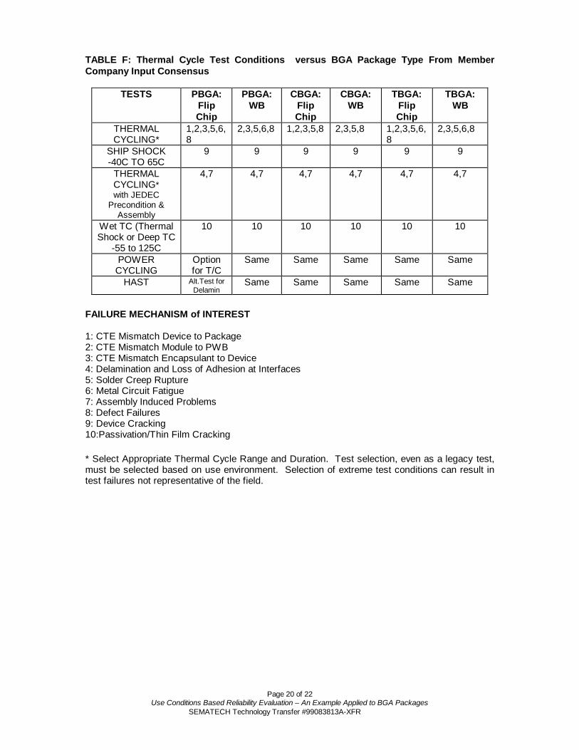
TABLE F: Thermal Cycle Test Conditions versus BGA Package Type From MemberCompany Input Consensus
TESTS PBGA:FlipChip
PBGA:WB
CBGA:FlipChip
CBGA:WB
TBGA:FlipChip
TBGA:WB
THERMALCYCLING*
1,2,3,5,6,8
2,3,5,6,8 1,2,3,5,8 2,3,5,8 1,2,3,5,6,8
2,3,5,6,8
SHIP SHOCK-40C TO 65C
9 9 9 9 9 9
THERMALCYCLING*with JEDEC
Precondition &Assembly
4,7 4,7 4,7 4,7 4,7 4,7
Wet TC (ThermalShock or Deep TC
-55 to 125C
10 10 10 10 10 10
POWERCYCLING
Optionfor T/C
Same Same Same Same Same
HAST Alt.Test forDelamin
Same Same Same Same Same
FAILURE MECHANISM of INTEREST
1: CTE Mismatch Device to Package2: CTE Mismatch Module to PWB3: CTE Mismatch Encapsulant to Device4: Delamination and Loss of Adhesion at Interfaces5: Solder Creep Rupture6: Metal Circuit Fatigue7: Assembly Induced Problems8: Defect Failures9: Device Cracking10:Passivation/Thin Film Cracking
* Select Appropriate Thermal Cycle Range and Duration. Test selection, even as a legacy test,must be selected based on use environment. Selection of extreme test conditions can result intest failures not representative of the field.

Page 21 of 22Use Conditions Based Reliability Evaluation – An Example Applied to BGA Packages
SEMATECH Technology Transfer #99083813A-XFR
Appendix BExamples of Finding Acceleration Factors, Activation Energy and Coffin-Manson
Exponent
Figure 1 is a Weibull plot of temperature cycle data taken on two different die sizes. Twoconditions of TC were used so the effects of die size and ∆T could be evaluated. The plot showsthe acceleration factor to be 2.3 for the TC condition. Using the Coffin-Manson model from 4 andsolving for the exponent “n” using AF = 2.3, ∆TS = 165°C and ∆TUSE = 100 we find a Coffin-Manson exponent “n” of 1.64
Figure 1Temperature Cycle 2 die sizes and 2 TC Conditions
-40C/125C & 0C/100C
A FTTS tress
use
n
=
∆∆
( )
∆∆
=
Use
S
TT
Ln
AFLnn
Best Fitn=1.64
-5
-4
-3
-2
-1
0
1
2
.01
.05.1
.2
.4
.6
.8
.9
.95
.99
1000 10000 100000
Cycles
1.2 X Die SizeEffect
2.3X CycleCondition

Page 22 of 22Use Conditions Based Reliability Evaluation – An Example Applied to BGA Packages
SEMATECH Technology Transfer #99083813A-XFR
Figure 2 is an Arrhenius plot of time to 10% wire pull fail versus bake temperature. The slope ofthe curve is the activation energy. We can also obtain the activation energy by determining theacceleration factor and using this in the Arrhenius equation after solving for EA. From the plot wedetermine the AF = 533 from 180°C to 300°C (453°K to 573°K). Using these numbers in theequation for EA below we find the activation energy to be 1.17 eV. This EA can now be used tocalculate the acceleration factor (AF) between any use/stress condition.
EA = 1.17
Figure 2Arrhenius Plot of Time to 10% wire pull fail
A F
Ek T TA
=−
ε
1 1
1 2
( )( )E
T T k Ln A FT TA =
−1 2
2 1
380 340 300 260 220 200 180 1600.1
1
10
100
1E3
1E4
Temperature (deg C, Arrhenius Scale)
Hours
6
3200
AF = =3200
6533
EA = 1.17


SEMATECH Technology Transfer2706 Montopolis Drive
Austin, TX 78741
http://www.sematech.orge-mail: [email protected]