use of cement-chelated solidified mswi fly ash for … · 2017-10-19 · use of cement-chelated...
TRANSCRIPT

Draft
Use of Cement-Chelated Solidified MSWI Fly Ash for
Pavement Material: Mechanical and Environmental
Evaluations
Journal: Canadian Geotechnical Journal
Manuscript ID cgj-2017-0007.R2
Manuscript Type: Article
Date Submitted by the Author: 06-Jul-2017
Complete List of Authors: Tang, Qiang; Soochow University, School of Urban Rail Transportation
Zhang, Yu; Soochow University Gao, Yufeng; Hohai University, Laboratory of Ministry of Education for Geomechanics and Embankment Engineering Gu, Fan; Texas A&M University Transportation Institute,
Keyword: Fly ash, freeze-thaw, cement-chelated stabilization/solidification, pavement material, finite element analysis
https://mc06.manuscriptcentral.com/cgj-pubs
Canadian Geotechnical Journal

Draft
Use of Cement-Chelated Solidified MSWI Fly Ash for Pavement Material: Mechanical and
Environmental Evaluations
Qiang Tang, Ph.D.
Associate Professor
School of Urban Rail Transportation
Soochow University
Yangchenghu Campus, Xiangcheng District, Suzhou 215131, China
E-mail: [email protected]
Yu Zhang
Master Candidate
School of Urban Rail Transportation
Soochow University
Yangchenghu Campus, Xiangcheng District, Suzhou 215131, China
E-mail: [email protected]
Yufeng Gao, Ph.D. (Corresponding Author)
Professor
Key Laboratory of Ministry of Education for Geomechanics and Embankment Engineering
Hohai University
No. 1# Xikang Road, Gulou District, Nanjing 210098, China
E-mail: [email protected]
Fan Gu, Ph.D.
Postdoctoral Research Associate
Texas A&M Transportation Institute
Texas A&M University System
3135 TAMU, CE/TTI Bldg. 501A, College Station, Texas 77843, USA
Phone: (979) 458-5729, Email: [email protected]
Page 1 of 52
https://mc06.manuscriptcentral.com/cgj-pubs
Canadian Geotechnical Journal

Draft
Abstract:
As a by-product from the incineration of Municipal Solid Waste (MSW), fly ash usually
contains mobile heavy metals that may engender severe pollution for reuse. In this study, fly ash was
solidified with cement and chelating agent to immobilize these polluting elements. The possibility of
using the solidified fly ash for pavement materials was also assessed through mechanical and
environmental perspectives. According to the results, the strength of solidified fly ash was found
proportional to both the cement/fly ash ratio and curing time. This indicated that the increase of fly
ash loading reduced the concentration of products from cement hydration, and thus destroyed the
structure of products of hydration. With the increase of freeze-thaw cycles, the compressive strength
of cement-stabilized fly ash decreased from 7 to 14 days, and then increased from 14 to 28 days.
Subsequently, the finite element analysis showed that placing the solidified fly ash layer as pavement
materials between unbound base course and subgrade was beneficial to prolong the fatigue life and
reduce the rutting distress of asphalt pavements. Finally, the metals leachability of the mixtures was
tested, which showed that leaching concentration decreased as the cement/ash ratio, curing time and
chelating agent content increased.
Keywords:
Fly ash, freeze-thaw, cement-chelated stabilization/solidification, pavement material, finite
element analysis
Page 2 of 52
https://mc06.manuscriptcentral.com/cgj-pubs
Canadian Geotechnical Journal

Draft
Introduction
Incineration is a commonly used method for managing the Municipal Solid Waste (MSW) in the
world. This is because it reduces the waste by about 70% in weight and 90% in volume (Ferreira et al.
2003; González et al. 2016). In Japan, the incineration percentage of solid waste is up to 75% in
2013 (Ministry of the Environment of Japan 2013). Meanwhile, approximately 50% of MSW were
treated by incineration in Europe (e.g., Denmark, Sweden, Switzerland, and Netherlands) (CEWEP
2013). Even though incineration is efficient for treating MSW, one of the shortcomings of this
technology is the production of a significantly large amount of solid residue (e.g., fly ash) (Sukandar
et al. 2009). It is estimated that MSW incinerators generate around 1.2 × 10⁶ tons of fly ash every
year in Western Europe (Fuoco et al. 2005). Due to the high content of heavy metals and the finesse
of their particles, the resulting fly ash is classified as hazardous waste, which requires special
managements (Pesonen et al. 2016; Luna et al. 2011).
Fly ash can be treated in several ways, including cement or geopolymeric solidification,
chemical stabilization using additives, thermal treatment via melting, and hydrothermal techniques
(Wang et al. 2015; Tang et al. 2016). At present, the most common and effective method to handle
MSWI fly ash is stabilization/solidification treatment using cementitious materials, of which
Portland cement has been successfully used to treat hazardous waste for a long time (Chen et al.
2009; Malviya and Chaudhary 2006; Su et al. 2016). Cement acts as an immobilization agent for
trace elements and it develops hardening reactions that increase geotechnical stability of material
mixture in a landfill (Zhang et al. 2016). However, the large quantity of cement required to
endeavour enough mechanical strength to the final monolith is the foremost disadvantage of this
technology, which makes the final mass double in volume (Quina et al. 2010). Meanwhile, traditional
Page 3 of 52
https://mc06.manuscriptcentral.com/cgj-pubs
Canadian Geotechnical Journal
Draft
cement solidification technology presents many other deficiencies, such as weak acid resistance and
poor durability (Jin et al. 2016). In order to solve such problems, chemical stabilization has been
used to immobilize heavy metals without change of material structure (Quina et al. 2010; Bontempi
et al. 2010). This treatment using chelating agents owes to their complexation of heavy metals with
an organic sulphide group (Hong et al. 2000; Sukandar et al. 2009).
Even though the treatments described above can be very effective on fixing the various potential
toxic components of fly ash, another question is raised, namely what to do with the treated residue.
Due to the limited space and high cost of land disposal, ashes have emerged as construction or
geotechnical materials or have been proposed for such applications (Anastasiadou et al. 2012;
Cheeseman et al. 2003). According to Cai et al. (2004), pretreated fly ash could be applied in
cement-treated base layers for roads and pavements without significantly compromising compressive
strength or leaching of salts and heavy metals as investigated in tank leaching experiments. In
Germany, up to 50% of the ash generated from incinerated waste was used for the manufacture of
sound insulation in walls along highways and sublayers of city roads. In India, about 25% of fly ash
is applied to cement production, construction of roads and brick manufacture (Bhattacharjee and
Kandpal 2002). In Denmark, over 72% of the ash was reused for the construction of parking lots,
cycling tracks and other roads (Anastasiadou et al. 2012).
In cold regions, the weathering conditions, which are referred as freeze-thaw cycles, have a
significant effect on both the durability and performance of earthwork structures, such as
embankments and highway projects. Freeze-thaw is considered as one of the crucial causes for
significant damage to earthwork structures (Kamei et al. 2012). However, the strength characteristics
and heavy metal toxicity of fly ash solidified with cement and chelating agent under the
Page 4 of 52
https://mc06.manuscriptcentral.com/cgj-pubs
Canadian Geotechnical Journal

Draft
freezing-thawing cycles have not been systematically studied.
According to the aforementioned research needs, MSWI fly ash is solidified with cement and
chelating agent in this study. The influence of cement content, chelating agent content, curing time
and alternative cycles of freeze-thaw is firstly evaluated in terms of the compressive strength, failure
strain, weight loss and secant modulus loss. The mechanism of freeze-thaw induced deterioration is
then comprehensively investigated. Subsequently, the finite element program is used to investigate
the benefits/disbenefits of application of solidified fly ash in roads. The final section summarizes the
major findings of this study.
Materials and method
Materials
The fly ash used in this study was collected from municipal solid waste (MSW) incineration
facility at the Changshu municipal solid waste landfill in Suzhou, China. The landfill has a total
storage capacity of 3.98 million m3. Approximately 1500 tons (t)/day of MSW was deposited at this
location. Among them, around 900 t/day MSW was incinerated for electricity generation. During the
incineration, the techniques for cleaning flue gas mainly include a semi-dry scrubber, activated
carbon injection, and fabric filter. In this procedure, hydrated lime acts as a neutralizing agent in the
flue gas cleaning system, and is added to the reaction tower to absorb acid gases. Then the fly ash
and the reactants are removed when the flue gas passes through the baghouse. In Changshu landfill
site, over 25 t/day fly ashes were produced during MSW incineration. As a solidified material, the
commercially available Portland cement (i.e., PG325) was prepared. In order to stabilize heavy
metals in the fly ash, chelating agent was used in which dithiocarbamate is the main active group for
Page 5 of 52
https://mc06.manuscriptcentral.com/cgj-pubs
Canadian Geotechnical Journal
Draft
chelating heavy metals.
The maximum and minimum density of the fly ash were measured according to JGS 0162 and
JIS A 1224, respectively. The plastic and liquid limit were measured according to GB/T 50123-1999
by the apparatus (GYS-2, Nanjing Soil Instrument, China). The natural moisture content and water
retention capacity of the fly ash were measured following JIS A 1203 and JGS 0151, respectively
(Tang et al., 2014, 2015). In accordance with JIS A 1218, hydraulic conductivity was obtained using
a permeameter (TST-55, Jingkeyusheng, China). EC and pH of the samples were tested using a
pH/EC meter (PH-2603, Lohand, China) following JGS 0212 and JGS 0211, respectively. In addition,
grain size distribution of fly ash was determined according to GB/T50123-1999. Concerning the
N2-BET adsorption test, it was conducted to analyze specific surface area, average pore diameter and
micropore volume (Diameter<102.12 nm) of fly ash (NOVA2000e, Quantachrome, U.S.). The
elemental and mineral composition of fly ash and cement were analyzed by XRF (JSX-3400R, JEOL,
Japan) and XRD (RAD-2B, Rigaku Corporation, Japan) correspondingly.
Preparations of samples
Both fly ash and Portland cement were dried under 105°C for at least 24 hours by using oven
(101-A, Leao, China) to ensure the satisfied quality during the experiment, since there might be some
moisture content in them. Subsequently, they were cooled to room temperature in a desiccator. The
fly ash was then added with the stabilizing agent, which was diluted by adding water, with the
concentration of 3%, 6%, 9% (w/w) each. The mixture was stirred and chelated thoroughly, allowed
to settle for 24 h at room temperature, dried at 105°C and then pulverized. After that, the chelated fly
ash was homogenized with the cement at four different ratios of cement/fly ash (10%, 20%, 30% and
Page 6 of 52
https://mc06.manuscriptcentral.com/cgj-pubs
Canadian Geotechnical Journal

Draft
40%) by using a blender for 2-3min. Water was added slowly into the dry mix to promote hydration
and the moisture contents maintained at 60%. After the mixing procedure, the mixture was
transferred into the moulds (70 mm× 70 mm× 70 mm, Jianyi, China), which were then sealed with a
polyethylene membrane to avoid severe dehydration. Afterwards, the mixtures were left undisturbed
for 24 h at room temperature (23 ± 2°C) and high relative humidity (>50%). Three replicates were
analyzed for each trial. After the period of the initial setting, the mixtures were demoulded and cured
(90 ± 2% humidity, 20 ± 2°C) for 7, 14, 28 days in a curing box (HBY-15B, Donghua, China).
In this study, the cyclic freeze-thaw test was conducted in the accelerated freeze-thaw testing
apparatus. In a freeze-thaw cycle, the temperature of samples cooled from 10°C and was lowered in
1 h with a constant cooling rate of 20°C/h. It was kept constant for 2 h at -10°C and increased in 1 h
with a constant heating rate of 20°C/h. It was kept constant for 2 h at 10°C. The samples were
subjected to the required number of freeze-thaw cycles (up to 5 cycles and 10 cycles) because
ultimate stresses of treated samples under lower confining pressure do not almost change in the
freeze-thaw cycle more than 3 (Kamei et al. 2012b; Wang et al. 2007). They were then tested to
evaluate how freeze-thaw cycles affect the durability of fly ash stabilised with cement. The 70 mm
cubes were used to examine the weight loss, secant modulus loss, compressive strength loss and
failure strain at every 5 freeze-thaw circulations. All experiments were performed on three specimen
replicates. The average values were used for the discussion of the test results.
The measurement of compressive strength property was conducted according to the GB/T
50081 (2002) method. The following Eq. (1) was used to calculate the compressive strength:
A
Ffcc = (1)
where fcc is the compressive strength (MPa), F is the maximum load (N) and A is the area of the
Page 7 of 52
https://mc06.manuscriptcentral.com/cgj-pubs
Canadian Geotechnical Journal

Draft
cube loading face (mm2).
The measurement of failure strain was determined by Eq. (2):
L
Lf
∆=ε (2)
where fε is the failure strain (%), L∆ is the displacement at the maximum of stress (mm),
L is the height of the sample (mm).
The following Eq. (3) was used to calculate the weight loss:
%100×−
=∆o
non
W
WWW (3)
where ΔWn is the weight loss of specimens at every 5 freeze–thaw cycles (%),Wo is the average
weight of concrete specimens before freeze–thaw cycles (kg) and Wn is the average weight of
concrete specimens at every 5 freeze–thaw cycles in water (kg).
The secant modulus is a deformation parameter, which was determined by Eq. (4):
f
2/150
2ε
σ=E (4)
Where 50E is secant modulus, 2/1σ is compressive stress (MPa), when compression strain is
half of the failure strain and fε is failure strain (%).
According to the test procedure, the deterioration of the specimens was investigated by
determining the compressive strength loss, failure strain, weight loss and secant modulus loss.
Compressive strength test method
Whether samples under standard curing condition or after accelerated freeze-thaw cycles, both
of them were prepared for compression test. The unconfined compression tests were conducted as
per ASTM D 2166-91 using a microcomputer controlled electronic testing machine (LDS-50,
Page 8 of 52
https://mc06.manuscriptcentral.com/cgj-pubs
Canadian Geotechnical Journal
Draft
Chenda, China) with a vertical displacement rate of 1 mm/min. The strength (MTS 10/GL) had a
normal loading capacity of 50 kN, following by Koohestani et al. (2016). Total maximum loads were
recorded at the point of fracture and the compressive strength was determined using the formula
P=F/A, where P is the compressive strength (MPa), F is the total maximum load (N), and A is the
area of loaded surface (mm2). Based on the accuracy of the experiment, all of these tests were
conducted in replicate and the average values were reported. All of samples were prepared in
duplicate.
Finite element modeling of pavements with/without solidified fly ash
The finite element models were developed to assess the structural capacity of pavements with
and without solidified fly ash. As illustrated in Figure 1a, the control pavement consisted of 15-cm
hot mix asphalt (HMA), 25-cm unbound base, and 1.5-m subgrade. For the pavement containing
solidified fly ash, a 5-cm solidified fly ash layer was placed between unbound base course and
subgrade. A 565 kPa traffic load was uniformly applied in the center of pavements. The
corresponding critical responses (i.e., stress/strain at critical locations) were computed to evaluate the
long-term performance (i.e., rutting and fatigue cracking). Thereby, the benefits/disbenefits of
solidified fly ash as pavement material were quantified. The finite element analysis also took into
account the influence of freeze-thaw cycles on the long-term pavement performance. Figure 1b
presents one example of meshed axisymmetric finite element model. Fine mesh was used in the
vicinity of the load. The HMA, base course and subgrade were represented as 8-node biquadratic
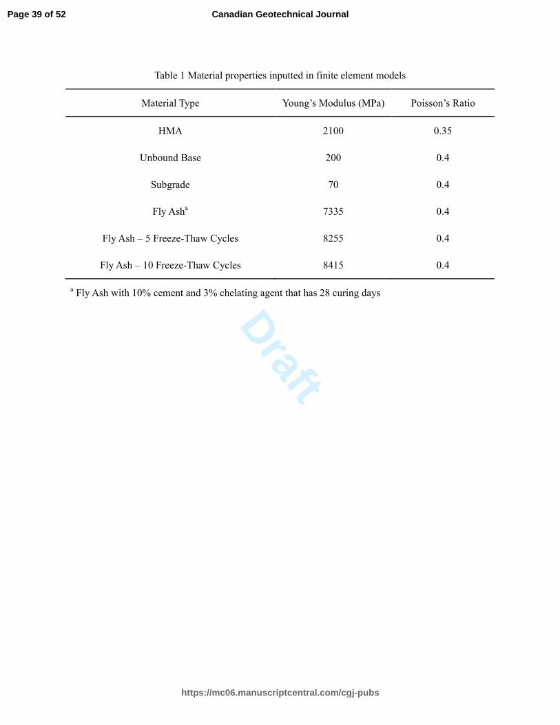
homogeneous solid elements with reduced integration. Table 1 shows the materials properties used in
the finite element models. The Young’s modulus of solidified fly ash was calculated based on an
Page 9 of 52
https://mc06.manuscriptcentral.com/cgj-pubs
Canadian Geotechnical Journal

Draft
empirical equation, as shown in Equation 5.
3445 1000ccE f= + × (5)
where E is the Young’s modulus of solidified fly ash (unit: MPa); and ccf is the unconfined
compressive strength (unit: MPa).
Fig. 1
Table 1
Leaching test method for heavy metal
The crushed samples collected after the compressive strength test were oven dried at 105°C for
24 h. Then the dried samples were further crushed manually until the particle size was less than 9.5
mm. Aliquots of the 50 g of the crush samples were put into a polyethylene bottle and leached using
an extraction buffer of acetic acid and sodium hydroxide (pH 2.88 ± 0.05) at a liquid/solid radio of
20 : 1, and vibrated at 30 rpm and 25°C for 18 h. The extract was filtered into a 100 mL flask by a
0.45µm pore size syringe filter, and then acidified by nitric acid to pH < 2. Subsequently, the
concentrations of targeted potentially toxic metals in the resulting filtrate were measured using
Atomic Absorption Spectroscopy (AAS) (TAS-990, Persee General, China). All the samples were
prepared in duplicate.
Results and discussion
Characterization of the materials
The physical and chemical properties were listed in Table 2. The natural moisture content of the
fly ash is 2.5%. The maximum and minimum density are 0.78 and 0.51 g/cm3, respectively. The
Page 10 of 52
https://mc06.manuscriptcentral.com/cgj-pubs
Canadian Geotechnical Journal
Draft
plastic limit and liquid limit of fly ash are 54.42% and 85.36%, respectively. The swell index is 4.00
mL/2g-solid, which represents the non-swelling characteristic. The fly ash disposal exhibits an
alkaline feature, which has a pH value of 12.59. The EC value of fly ash is 78.3 mS/cm, which
demonstrates that a large amount of soluble salt exists in fly ash and thus increases the difficulty in
immobilization. The hydraulic conductivity of fly ash is 8.92 × 10⁻⁷ m/s. The diverse hydraulic
conductivities can be attributed to the difference in the particle size. The water retention capacity is
128.7%. Particle size distribution curve of four different fly ashes is shown in Fig. 2. Compared with
the three other fly ashes (S1, S2, S3) used by Zhai et al. (2016), the particle size of the fly ash used in
this study is finer, which is due to the different composition of waste material.
Concerning the N2-BET adsorption tests, the correlation coefficient was 0.999, indicating that
the results obtained were reliable. The specific surface area of the fly ash used in this study is 8.008
m2/g. The average pore size is 84.81 Å, and the micropore volume is 1.812 × 10⁻² mL/g. The
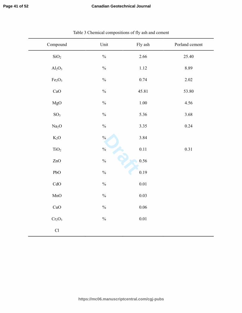
quantitative analysis of the fly ash samples, obtained by the X-ray fluorescence (XRF) spectrometer,
is shown in Table 3, together with the results for a 100% cement sample. Note that the major
elements of the fly ash were SiO2 (2.66%), Al2O3 (1.12%), CaO (45.81%), MgO (1.00%), SO3
(5.36%), Na2O (3.35%) and K2O (3.84%), while the major elements of the cement were SiO2
(25.40%), Al2O3 (8.89%), Fe2O3 (2.02%), CaO (53.80%), MgO (4.56%) and SO3 (3.68%),
respectively. Comparing the presented results with previous studies on the composition of fly ash, a
complete agreement was observed concerning the types of oxides that were present in the fly ash (He
et al. 2016; Anastasiadou et al. 2012; Sobiecka et al. 2014; Luna et al. 2011). It can be seen that the
sum of chemical compositions listed in Table 3 is not 100%. There may be two important reasons for
this phenomenon: on the one hand, X-ray fluorescence (XRF) can only be used to determine the
Page 11 of 52
https://mc06.manuscriptcentral.com/cgj-pubs
Canadian Geotechnical Journal

Draft
element content, not to quantify the mineral composition. And the test results of XRF are expressed
in the form of oxides. Fly ash is mainly composed of metal oxide and nonmetal oxide. However, the
same or similar components can have different phase structure (Karlfeldt and Steenari 2007). Take
calcium for an example, in XRF, it appears in the form of CaO. In X-ray diffraction (XRD), as
shown in Fig. 3, it can be seen that the element calcium exists in a variety of forms, such as CaCO3,
CaClOH, Ca(OH)2, Ca(OH)2•4H2O and so on. So, the use of calcium oxide to represent the content
of calcium, the total number of elements will be reduced. Except for calcium, other elements and
their compounds have similar phenomena. On the other hand, the detection range of the majority of
modern laboratory XRF instruments is between sodium (Na) and uranium (U) (Shackley 2012).
Unfortunately, as shown in Fig. 3, the fly ash contains crystal water, which cannot be detected. The
highest content of CaO in fly ash was due to its lime pretreatment for acid gas scrubbing (Mu et al.
2017). In the acid gas removal reactor, there is a special device where the quick lime reacts with
water to produce calcium hydroxide and subsequently the calcium hydroxide is mixed with a large
amount of fly ash. The surface moisture of fly ash enhances the sorption of acid gases to promote the
neutralization reaction. Therefore, fly ash mixed with the neutralizer residue and the content of
calcium increased to 45.81% (Su et al. 2015). According to X-ray diffraction (XRD) analysis, the
investigated fly ash sample had a highly complex mineralogy. As shown in Fig. 3, the main
crystalline compounds were calcite (CaCO3), halite (NaCl) and sylvite (KCl). In addition, the
presence of crystal structures, such as calcium chlorite hydroxide (CaClOH), silicon chloride (SiCl4),
calcium chloride hydrate (Ca(ClO)2•4H2O), iron sulfide (FeS) and portlandite (Ca(OH)2) were also
verified. According to the diffraction pattern obtained by XRD, the main components of this sample
include calcium chloride hydroxide, halite, silver aluminum sulfide, silicon chloride, stannite and
Page 12 of 52
https://mc06.manuscriptcentral.com/cgj-pubs
Canadian Geotechnical Journal

Draft
sylvite, which confirms the results of XRF. The amorphous phase was also abundant in fly ash (Alba
et al. 1997). Fly ash can be regarded as essentially consisting of three types of components:
crystalline minerals, unburnt carbon particles, and non-crystalline aluminosilicate glass (Ward and
French 2006). According to Kenworthy et al. (1980), amorphous phase was found to account for
about 40% of the total amount of fly ash by EPMA (Electron Probe Micro Analysis). Fig. 3, XRD
diffraction pattern, shows many small, corrugated peaks, which means fly ash contains large amounts
of amorphous glass material (Liang et al. 2014). Glass is amorphous or non-crystalline, and does not
have regular arrays of atoms that produce definitive peaks in XRD studies. Broad patterns or
“humps” may nevertheless be seen in X-ray diffractograms derived from different types of glassy
materials. Along with an overall reduction in the peak intensities derived from the crystalline
components, due to dilution and/or mass absorption effects, these humps provide an indication that
glass is present in fly ashes and other samples subjected to XRD analysis (Ward and French 2006).
The amorphous phase cannot be measured by XRD, however, its content and chemical composition
can be estimated from chemical and XRD data (Ward and French 2006; Ward et al. 2001). Expected
heavy metal rich mineral phases (such as PbCl2 or K2ZnCl2) have not been identified. In most cases,
the heavy metals in fly ash are enriched in the amorphous phase, and the distribution in the crystal
phase is very small. Different authors suggest separation methods (magnetic and density separation)
to concentrate over 2% on heavy metal crystalline phases (Eighmy et al. 1995; Kirby et al. 1993).
Table 2
Table 3
Fig. 2
Fig. 3
Page 13 of 52
https://mc06.manuscriptcentral.com/cgj-pubs
Canadian Geotechnical Journal

Draft
Compressive strength test results
Fig. 4 (a) shows the compressive strength of cement-based solidification samples, pretreated
with chelating agent (3%, 6% and 9%), and under ordinary curing conditions for 7 to 28 days. It was
found that the strength decreased as the percentage of cement loading reduced. As shown in Fig. 4
(a), based on 3% chelating agent mixed, the compressive strength of cement-based matrices
(cement/ash = 10%, 20%, 30% and 40%) after 7 days of solidification are 0.38 MPa, 1.18 MPa, 1.64
MPa and 1.65 MPa respectively. The products of cement hydration are lapped and bound by the
multiple gravitation. This is the reason why cement blocks have a high compressive strength.
However, the residues in fly ash that are not completely burnt can influence the compressive strength
of the solidified matrix. Due to the presence of fly ash, the high levels of residues in fly ash not only
reduce the concentration of products from cement hydration, which have connection effect, but also
destroy the structure of products of hydration (Liu et al. 2008). Meanwhile, the residues also have a
certain influence on the delay of the setting time. The reason for this is that the residues are porous
and hydrophobic. So the cement clinker can easily be wrapped in the inner of the carbon hole of the
residues to form a protective film, which hinders the full contact of the water with the cement clinker,
so as to disturb the hydration reaction and delay the setting time of the cement.
As can be observed in Fig. 4 (a), the compressive strength of the solidified matrix increases with
curing time. Compared to 7 days of curing with 3% chelating agent, the compressive strength of
mixtures with 10%, 20%, 30% and 40% cement content for 28 days increases by 915%, 166%, 147%
and 207%, respectively. This is because the hydration reaction is more sufficient when the curing
time is longer. Two processes are involved during the period of cement hydration reaction. One is
Page 14 of 52
https://mc06.manuscriptcentral.com/cgj-pubs
Canadian Geotechnical Journal

Draft
through-solution hydration, which involves several factors including dissolution of anhydrous
compounds into their ionic constituents, formation of hydrates in the solution, and eventual
precipitation of hydrates from the supersaturated solution. The other is solid-state hydration of
cement and the reactions occurred directly at the surface of the anhydrous cement compounds.
During this period, no compounds dissolve into solution. In the early stage of cement hydration,
through-solution hydration is dominant. At the post-stage of cement hydration, the hydration of
residual cement particles may occur by the solid-state reactions and the migration of ions in the
solution becomes restricted (Mehta and Monteiro 2014).
Chelating agent content has a certain effect on the strength of the solidified ash. As shown in
Fig. 4(a), in the early stage (7-14 days), when the cement content is less than 20%, the unconfined
compressive strength of the mixtures decreases with the increase of the chelating agent content;
when the cement content is higher than 20%, the strength of the mixtures has no significant change.
The compressive strength is relatively low in the early stage, which demonstrates that the presence of
heavy metals such as Zn2+ and Cu2+ has a negative effect on the hydration reaction of cement and
hinders the hydration reaction of cement. When the cement content is at a low level, the heavy metals
Al3+, Pb2+ are mainly affected by the stabilizing effect of the chelating agent. On one hand, the
chelating agent consumes cement and a large amount of SiO2, Al2O3, CaO in fly ash, which results in
the reduction of the materials that contribute to the hydration and pozzolanic reaction. Thus, the
macroscopic exhibition is that the hydration and pozzolanic reaction is inhibited. On the other hand,
the free heavy metal ions in fly ash decrease significantly by the chelation, which simultaneously
promotes the hydration of cement. Therefore, the macro performance shows a slight decrease in
strength. In the late stage, when the chelating agent content increases from 3% to 6%, the
Page 15 of 52
https://mc06.manuscriptcentral.com/cgj-pubs
Canadian Geotechnical Journal
Draft
compressive strength of the mixtures significantly increases. While the compressive strength of the
mixtures decreases slightly when the content of chelating agent continued to increase to 9%.
It is well-documented that the compressive strength and failure strain of cement-based samples
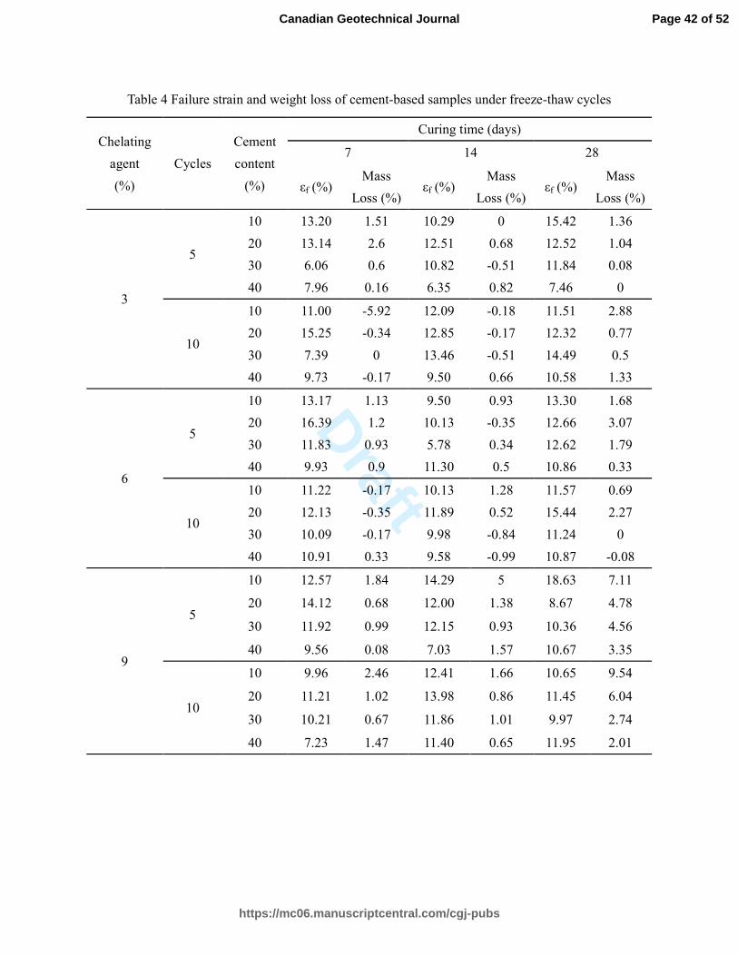
can reflect directly the deterioration degree caused by freeze-thaw attacks. Figs. 4(b) and 4(c) show
the compressive strength of cement-based mixtures under different freeze-thaw cycles. Table
4 shows the variation of applied pressure versus the strain of cement-based samples subjected to 5
and 10 freeze-thaw cycles. It can be seen that the cement content has a significant influence on the
compressive strength and failure strain of mixtures, which are exposed to freeze-thaw cycles. With
the increase of cement content from 10% to 40%, the compressive strength of the specimens
significantly increases at 14 days. However, the increase of compressive strength is relatively flat at
7 days and 28 days. As shown in Table 4, under the condition of 5 freeze-thaw cycles, 3% chelating
agent and 28 curing days, the failure strains of the mixtures with 10%, 20%, 30% and 40% cement
content are 15.421%, 12.521%, 11.843% and 7.464%, respectively.
In the process of freezing and thawing water firstly enters the biggest pores of hardened
cement paste and subsequently reaches the smaller pores. According to Everett (1961), ice crystals in
the pores tend to grow continuously and penetrate deeper into smaller pores of the hardened cement
paste and thus fill capillary pores with water or freezing solution. When water or freezing solution
freezes, i.e. the volume increases by 9%, the hardened cement paste generates internal stresses, and
finally crumbles (Everett and Haynes 1965). According to Kalliopi (2006), the destructive effect
during freezing depends on the content of water in hardened cement paste. Based on Table 2, the
water retention capacity and specific surface area of the fly ash is 128.7% and 7.944 m2/g,
respectively, which indicates that the more fly ash is added, the more water is attracted. Thereby, the
Page 16 of 52
https://mc06.manuscriptcentral.com/cgj-pubs
Canadian Geotechnical Journal

Draft
compressive strength of fly ash mixtures decreases accordingly.
As shown in Fig. 4 (b) (c), the unconfined strength of the mixtures decreases by increasing the
number of freeze-thaw cycles at 7 and 14 days. During freezing phase, ice crystals are formed and
then, during thawing phase, these crystals start to melt and free water appears in the sample. The free
water moves to lower parts of the sample due to gravity force. Consequently, upper parts of the
specimen lose their moisture and the adhesion between fly ash and hydrate particles becomes weaker.
Therefore, the cement-based samples in thawing phase cannot return to its initial situation before
freezing. This phenomenon also leads to the increase of volume of sample. The structures of samples
deteriorate when such freeze-thaw action is repeated (Ghazavi and Roustaie 2010). However, at the
curing time of 28 days, the compressive strength of the samples subjected to 10 cycles is greater than
the samples experienced 5 cycle attacks. According to Chang et al.(2014), the mechanical properties
of studied soil are affected considerably by the number of freezing-thawing cycles, and after 7-9
freeze-thaw cycles, the compressive strength reaches the minimum value. According to Su et al.
(2008), the physico-mechanical characters of the investigated soils become stable after 10
freezing-thawing cycles,such as water content,density,cohesion,and internal friction angle.
Generally, the cohesion of the samples increases with the repeated freezing-thawing cycles.
In general, the loss of weight and/or the decrease of secant modulus is used to evaluate the
degradation in freeze-thaw tests. As shown in Table 4, it can be observed that weight loss of
cement-based samples decreases as the cement/fly ash ratio increases. Under the condition of 5
freeze-thaw cycles and 28 curing days, the weight losses of different mixtures (cement/ash = 10%,
20%, 30% and 40%) are 1.36%, 1.04%, 0.08% and 0% with 3% chelating agent; 1.68%, 3.07%,
1.79% and 0.33% with 6% chelating agent; and 7.11%, 4.78%, 4.56% and 3.35% with 9% chelating
Page 17 of 52
https://mc06.manuscriptcentral.com/cgj-pubs
Canadian Geotechnical Journal

Draft
agent. Meanwhile, it can be clearly seen that the chelating agent content affect the resistance of
mixture to the freeze-thawing negatively. The weight loss of samples indicates that the bonding of
aggregates and gelled materials are damaged, thereby causes aggregates to break away from the
specimen and results in mass reduction (Chen et al. 2014). According to Wu (1979), the pores can be
classified into four grades: harmless pores, less harmful pores, harmful pores and serious damage
pores. Harmless pores, which have a diameter of less than 20 nm, and with pore grade that is not
damaged in terms of mechanical strength, permeability, and durability of the specimens; less harmful
pores, with pore diameter greater than 20 nm and less than 50 nm, and with pore grade that has a
minor damage for the performance of the specimens; harmful pores, with pore diameter more than
50 nm and less than 200 nm, and with pore grade that has damage for the performance of the
specimens; and serious damage pores, with pore diameter greater than 200 nm, and with pore grade
that has serious damage for the performance of the specimens (Wu 1979; Wang and Niu 2016). The
porosity and pore grade of the specimens change with the prolonged period of positive and negative
temperature alternation. The volume percentage of the harmless pores in the specimens reduces, and
the porosity of the pores whose diameter is more than 20 nm increases. The volume percentage of
each pore grade is obviously transformed when the number of freezing and thawing cycles increases.
The content of the pores with diameter less than 20 nm is low. Nevertheless, the content of the three
other pore grades and their porosity significantly increases. Therefore, the microstructure of the
specimens is incompact. The relative dynamic elasticity modulus and the relative mechanical
properties are small, and the weight loss rate is great. (Wang and Niu 2016)
Fig. 5 shows the secant modulus of cubic samples under freeze-thaw cycles. As illustrated,
when the chelating agent is 3%, the secant modulus ranges of samples with different mix ratios are
Page 18 of 52
https://mc06.manuscriptcentral.com/cgj-pubs
Canadian Geotechnical Journal
Draft
3.44 - 69.99 MPa (10%), 8.43 - 70.60 MPa (20%), 17.41 - 66.56 MPa (30%) and 7.57 - 120 MPa
(40%), respectively. In the case of the chelating agent with a mixing amount of 6%, the secant
modulus ranges are 9.74 - 54.39 MPa, 8.07 - 74.16 MPa, 17.55 - 101.24 MPa and 4.33 - 37.79 MPa,
respectively. With the chelating agent content is 9%, the secant modulus ranges are 4.97 - 31.21 MPa,
10.37 - 46.88 MPa, 10.07 - 55.11 MPa and 7.98 - 26.36 MPa, respectively. It can be observed that
curves of secant modulus rises at the initial alternative cement/ash ratios (10% - 30%). This
demonstrates that larger cement/ash ratio leads to a larger resistance to freeze-thaw attacks. Generally,
the cement-based samples with smaller weight loss in the freeze-thaw cycles have considerably
denser microstructure, and thus, exhibit larger value of relative secant modulus (He et al. 2016).
Meanwhile, these three figures present that there is a significant decrease in the secant modulus of
the samples when the cement content increases from 30% to 40%, which indicates that there is a
threshold value for cement content. When the cement content is higher than the threshold, the secant
modulus of samples will decrease. This may be due to two reasons. On one hand, there is plenty of
water needed during the process of hydration reaction and the excessive cement content can lead to
the lack of water, then, result in the incomplete hydration reaction. Using different length scales, four
composite media could be identified for cement pastes, including the C-S-H matrix, the hydration
products, the skeleton of cement paste and the cement pastes. And the physical properties of them are
different, so the secant modulus is not the same. On the other hand, there is a competition
phenomenon between the cement and the fly ash concerning the water absorption. When the cement
absorbs too much water, its bonding strength may not be as strong as the bonding strength of fly ash
in a certain moisture content. At a low water content level, the fly ash has the potential to form a
relatively dispersed particle, which cannot form a good-quality aggregate. Combined with the above
Page 19 of 52
https://mc06.manuscriptcentral.com/cgj-pubs
Canadian Geotechnical Journal

Draft
reasons, the secant moduli of the samples do not increase with the increase of cement content, but
show a downward trend.
Fig. 4
Fig. 5
Table 4
Finite element analysis
The Mechanistic-Empirical Pavement Design Guide (MEPDG) developed a fatigue cracking
model for asphalt pavements, which is shown in Equation 6.
2 3
1
1 1k k
f
t
N CkEε
=
(6)
where fN is the fatigue life of asphalt pavements, C is the laboratory to field adjustment factor,
1k , 2k , and 3k are model coefficients, tε is the tensile strain at the bottom of HMA layer, and E
is the stiffness of HMA. It is seen that the tensile strain at the bottom of HMA is a critical factor
affecting the fatigue life of pavements (Gu et al. 2016b). Figure 6 shows the comparison of tensile
strains at the bottom of HMA among the pavements with and without solidified fly ash. It is seen that
placing a solidified fly ash layer between unbound base course and subgrade reduces the tensile
strain at the bottom of HMA by 10% approximately. This indicates that the application of solidified
fly ash to asphalt pavement is effective in prolonging the fatigue life of pavements. Figure 1 also
shows that the number of freeze-thaw cycles has negligible influence on the tensile strain at the
bottom of asphalt pavements. This demonstrates that the solidified fly ash layer can prevent the
freeze-thaw induced cracking damage to asphalt pavements.
The MEPDG also pointed out that the rutting damage of subgrade significantly contributes to
Page 20 of 52
https://mc06.manuscriptcentral.com/cgj-pubs
Canadian Geotechnical Journal

Draft
the total rutting of asphalt pavements. The rutting damage of subgrade is mainly affected by the
compressive strain distribution in subgrade (Gu et al. 2015 and 2016a). Figure 7 compares the
compressive strain distributions in subgrade among the pavements with and without solidified fly ash.
It is shown that the pavements containing solidified fly ash have much less compressive strains in
subgrade than the control one (i.e., pavement without fly ash). This indicates that the solidified fly
ash layer is capable of reducing the rutting damage of subgrade, and thereby reducing the total
rutting distress of asphalt pavements. In addition, the compressive strain distribution of pavements
with solidified fly ash is not sensitive to the number of freeze-thaw cycles. This demonstrates that the
solidified fly ash layer also diminishes the freeze-thawing-induced rutting damage of asphalt
pavements. Therefore, it is concluded that placing the solidified fly ash layer between unbound base
course and subgrade is beneficial to prolong the fatigue life and reduce the rutting distress of asphalt
pavements.
Fig. 6
Fig. 7
Leaching test results
Suitability of application of cement-chelated solidified fly ash in regards to environmental
issues can be evaluated through leachate analysis. In view of the negative effects of leaching in most
applications, the allowable limit of leaching should be determined. Accordingly, the toxicity
characteristic leaching procedure (TCLP) from US Environmental Protection Agency (EPA) was
conducted to investigate the leaching behavior of heavy metals and the corresponding criteria.
According to Reijnders (2005), the leaching tests that are commonly used may be a poor indicator of
Page 21 of 52
https://mc06.manuscriptcentral.com/cgj-pubs
Canadian Geotechnical Journal

Draft
what happens in real life, and they may either overestimate or underestimate the actual leaching
amount. As for the allowable limit of leaching, Inyang et al. (2003) had brought forward a method to
calculate the maximum leachability that is acceptable for waste-amended construction materials on
the basis of a risk criterion. As expected, the quality of the maximum allowable concentration of
contaminant in the concrete increases as the concentration of the target contaminant specified in
drinking water standard agency increases. The TCLP leachates of the untreated fly ash contain high
concentration of Cd (6.4 mg/L) and Pb (15.5 mg/L), and certain amount of Cr, Cu, Zn and Ni. Fig. 8
presents the TCLP leaching test results of solidified fly ash samples after 7, 14 and 28 days of curing.
In Table 5, regulatory thresholds for filling materials in US and European countries are observed
(Saikia et al. 2008; Haugsten and Gustavson 2000). With the addition of 9% chelating agent and 30%
cement, the increase of the curing time to 28 day reduces the leaching concentration of Cr, Cu, Pb,
Zn, Ni and Cd to 0.05 mg/L, 0.09 mg/L, 0.1 mg/L, 0.21 mg/L, 0.1 mg/L and 0.02 mg/L, respectively.
Apparently, the concentration of selected elements in the leachates of cement-chelated solidified
MSWI fly ash meets the requirement from German, French, Austrian, Switzerland, Belgium and US.
In China, for the safe use of heavy metal-amended materials, relevant environmental quality
assessment standards were established, such as "Environmental quality standard for surface water"
(GB 3838-2002) and "Soil environmental quality standard" (GB 15618-1995). Meanwhile, based on
the characteristics of highway engineering, the "Specifications for environmental impact assessment
of highways" (JTG B03.2006) was developed. The surface water evaluation in highway engineering
of the latter standard is the same as the former two. Taking into account the heavy metals in the
solidified fly ash will eventually enter the soil and water, so "Soil environmental quality standard"
and "Environmental quality standard for surface water" are adopted to evaluate the acceptable
Page 22 of 52
https://mc06.manuscriptcentral.com/cgj-pubs
Canadian Geotechnical Journal
Draft
leaching of the treated fly ash as a roadbed material. Limit values of soil environmental quality and
surface water environmental quality are presented in Tables 6 and 7, respectively. With the addition
of 9% chelating agent and 40% cement, the increase of the curing time to 28 day reduces the
leaching concentration of Cr, Cu, Pb, Zn, Ni and Cd to 0.03 mg/L, 0.07 mg/L, 0.03 mg/L, 0.09 mg/L,
0.1 mg/L and 0.02 mg/L, respectively. It is obvious that the leaching concentration of heavy metals is
much smaller than the limit value of soil environmental, and all conform to the soil environment
quality standard. Meanwhile, the analysis results indicated that the concentrations of other metals
except Cd can achieve the water standard level Ⅴ, which is suitable for the agricultural water and
general landscape water. After the modification of fly ash, the influence of leaching concentration of
heavy metal on soil is almost negligible, which may have little negative effect on surface water.
Assessment of pollutant release cannot only be conducted by standard short-term leaching tests
but also long-term release studies (Ferreira et al. 2003; Reijnders 2005). Barna et al. (2000) proposed
a methodology for the modelling of long-term release from a water storage reservoir for fire control,
the bottom of which was constructed with MSW fly ash mixed with hydraulic binders and water.
Although the scenario cannot be considered as a common application, the developed methodology
can be used in other applications. Triano and Frantz (1992) evaluated the leaching behavior of
concrete containing fly ash. They reported limited amounts of heavy metals in the leachate, below
the toxicity limits according to the EPTOX toxicity procedure. According to Ferreira et al. (2003),
application as lightweight aggregates is not expected to pose environmental problems, since heavy
metal leaching is not significant when concrete is used under sheltered conditions. According to
Chen (2012), the degree of compaction also influences the leaching behavior of heavy metals. With
the increase of compactness, the leaching concentration of heavy metals decreases, which shows the
Page 23 of 52
https://mc06.manuscriptcentral.com/cgj-pubs
Canadian Geotechnical Journal
Draft
importance of ensuring a proper degree of compaction during construction.
As shown in Fig. 8, after 7-day curing, the leaching amounts of heavy metals decrease by
99.34% (Pb), 99.0% (Cd), and 86.41% (Ni) when compared to the untreated fly ash. The leaching
amounts of Cr, Cu and Zn reduce by the ranges of 86.36% - 91.71%, 50.95% - 64.94% and 53.82% -
92.73%, respectively. After 28 days of curing, the leaching amounts of heavy metals reduce by
99.37% (Pb), 99.07% (Cd), and 86.43% (Ni), respectively. The leaching amounts of Cr, Cu and Zu
decrease by the ranges of 86.49% - 93.54%, 51.35% - 68.42% and 64.65% - 95.43%, respectively.
Compared against the reduction of leaching amount of cement-based solidification utilized in Tang et
al. (2016), the reduction of leaching amount in this study is much higher. This indicates that the
solidification/stabilization of fly ash by cement and chelating agent has better fixation capacity.
According to Pesonen et al. (2016), cement-based solidifications were stable and the heavy metals
were immobilized well in the sample mortars during the long-term diffusion test, at least by the
physical encapsulation mechanism. In stabilization, the contaminants of a waste material are
converted into less soluble, mobile, or toxic forms through chemical processes, but the physical
characteristics of the waste are not changed by stabilization. In solidification, the waste material is
encapsulated in a solid monolithic block. The contaminants do not necessarily interact chemically
with the solidifying reagent. Instead, they are embedded in the solidified matrix by physical
processes. Solidification does not necessarily involve a chemical interaction between the wastes and
the solidifying reagents, but may mechanically bind the waste into the monolith. Contaminant
migration is restricted by vastly decreasing the surface area exposed to leaching and/or by isolating
the wastes within an impervious capsule (Conner and Hoeffner 1998). The distinction between
chemical and physical immobilization is frequently not clear, and both mechanisms operate
Page 24 of 52
https://mc06.manuscriptcentral.com/cgj-pubs
Canadian Geotechnical Journal

Draft
simultaneously. Briefly, chemical immobilization occurs at an atomic scale, whereas physical
immobilization occurs at a micron scale (Glasser 1997).
As shown in Fig. 8, with the increase of cement/ash ratio, the leaching concentration of heavy
metals decreases. When the curing time reaches 7 d and the addition of chelating agent is 9%, the
leaching concentration ranges of Cd, Pb, Zn and Cu are 0.06 - 0.04 mg/L, 0.12 - 0.09 mg/L, 0.6 - 0.4
mg/L and 0.08 - 0.07 mg/L respectively, which significantly reduces with the cement addition
increasing from 10% to 40%. Such a phenomenon is attributed to the following cement curing
mechanisms. (1) Physical Cementation and Adsorption. Calcium silicate hydrate (C-S-H), the
primary cementing and hardening chemical formed by hydration, is generated at the surface, which
acts as a barrier between the immobilized solid wastes and the surrounding liquids. The C-S-H
controls the potential adsorption of ions in the liquids onto the surface of the solid wastes as well as
the immobilization of heavy metals in the mixture. It has large surface area (10 - 50 m2/g), which
attribute to the massive adsorption with heavy metal ions. Thus, the leaching of pollutants accords
with environmental suitability (Sobiecka et al. 2014). (2) Double Decomposition Precipitation
Reaction. Based on the high alkaline environment, due to the cement hydration reaction, heavy metal
ions (such as Cd2+, Pb2+, Cr3+) were prevented from leaching in the form of low solubility of
hydroxide precipitation. (4) Isomorphous Substitution. Ettringite (Aft), another cement hydration
product, also makes a great contribution to the prevention of heavy metal leaching. Heavy metal
cations can be firmly bounded in the cement structure by substituting the cations in the ettringite
crystal structure. For example, Zn2+, Cd2+, Pb2+, Ni2+ and Al3+ will substitute Ca2+ in the ettringite
crystal structure, and Al3+ in ettringite crystal structure can be replaced by Cr3+, Mn3+, Ti3+, Ti4+, Si4+.
The distinction between chemical and physical immobilization is frequently not clear, and
Page 25 of 52
https://mc06.manuscriptcentral.com/cgj-pubs
Canadian Geotechnical Journal

Draft
aforementioned curing mechanisms operate simultaneously. According to Yousuf et al. (1992), zinc
retards the hydration and setting of cement by the surface precipitation of an amorphous layer of zinc
hydroxide on the anhydrous clinker grains, and that calcium hydroxide reacts with the zinc
hydroxide to form CaZn2(OH)6•2H2O. According to Lin et al. (1994), the major cement component,
dicalcium silicate (C2S) was used as a model solidification agent to solidify/stabilize the copper
oxide. And the mechanisms in which CuO is confined in the C2S paste system can be explained as
physical encapsulation and chemical stabilization. Furthermore, the formation of a solid solution of
Cu-Ca-Si compounds is also a major solidification/stabilization mechanism (Lin et al. 1994).
Obviously, reduction of heavy metals leaching potential is observed as a function of the
stabilization time. As shown in Fig. 8, based on 9% chelating agent and 40% cement mixed, after 7,
14 and 28 days of solidification of fly ash, the leaching values of Pb are 0.09 mg/L, 0.07 mg/L and
0.03 mg/L respectively, the leaching concentrations of Cd are 0.05 mg/L, 0.04 mg/L and 0.03 mg/L
respectively, and the leaching values of Cr are 0.08 mg/L, 0.05 mg/L and 0.03 mg/L respectively. The
leaching concentration gradually decreases with the increasing curing time. The sustained hydration
reaction of cement provides a high alkaline environment, in which the low solubility of hydroxide
precipitation (Pb(OH)2, Cd(OH)2, Cr(OH)3) can be formed. Meanwhile, this phenomenon shows the
influence of pH value on the stability of solidified heavy metals. The increase of pH value results in
a higher immobilization of the heavy metals. According to Thevenin and Pera (1999), lead fixation is
due to a double phenomenon: first the precipitation of a metallic hydroxide and then encapsulation of
this compound in the C-S-H phase. It is confirmed that Pb immobilization in calcium silicate hydrate
(C-S-H) occurs as soon as C3S begins to hydrolyze. The “Pb-C-S-H” is referred as a C-S-H of
regular stochiometry where lead replaces calcium. According to Dimitris and Meng (2003), in the
Page 26 of 52
https://mc06.manuscriptcentral.com/cgj-pubs
Canadian Geotechnical Journal

Draft
presence of chromate ions and during ettringite formation, chromate will substitute sulfate in the
ettringite crystal structure to form what is known as Cr-substituted ettringite.
In addition, chemical solidifying agents also shows a superior solidification performance for
heavy metals. As shown in Fig. 8, the leaching concentration ranges of Pb with the addition of 3%,
6% and 9% chelating agent are 0.10 - 0.14 mg/L, 0.09 - 0.11 mg/L and 0.06 - 0.10 mg/L respectively,
which indicates that the chelating agent used in this study exhibit good stability. The chelating agent
contains two dithiocarboxy chelating groups, and thereby has an extraordinary binding capacity and
stability. The chelating equation of this chemical solidifying agent with the heavy metals is illustrated
in Fig. 9. It is illustrated that the coordination complex for this chelating agent is a straight-line
structure for its two thiolate groups, known as coordination polymerization precipitation in
Coordination Chemistry (Wang et al. 2015).
Fig. 8
Fig. 9
Table 5
Table 6
Table 7
Conclusions
This study demonstrated the influence of cement content, chelating agent content, curing time
and the number of freeze-thaw cycles on the strength characteristics and heavy metal toxicity of
solidified fly ash. The major findings were summarized as follows.
(1) According to the compressive strength test results, the compressive strength of the mixtures
Page 27 of 52
https://mc06.manuscriptcentral.com/cgj-pubs
Canadian Geotechnical Journal
Draft
grew with the increase of cement/fly ash ratio and curing time. In the early stage (7 - 14 days), based
on less than 20% chelating agent, chelating agent content affects compressive strength negatively.
With the increase of freeze-thaw cycles, the compressive strength of cement-stabilized fly ash
decreased from 7 to 14 days, and then increased from 14 to 28 days.
(2) The loss of weight and/or the decrease of secant modulus were measured to evaluate the
degradation in freeze-thaw tests. According to results, with the increase of cement content, the
weight loss of the samples decreased and the secant modulus first decreased (cement/ash: 10% - 30%)
and then increased (cement/ash: 30% - 40%). On the contrary, chelating agent content is proportional
to the weight loss and affects the resistance of mixture to the freeze-thawing negatively.
(3) Placing the solidified fly ash layer between unbound base course and subgrade was
beneficial to prolong the fatigue life and reduce the rutting distress of asphalt pavements. The
number of freeze-thaw cycles has negligible influence on the performance (e.g., fatigue cracking and
rutting) of pavements containing the solidified fly ash layer.
(4) Compared with cement-based solidification, the cement-chelated solidification is of more
environmental suitability. For the leaching test results, it was shown that the leaching concentration
of heavy metals decreased as the cement/ash ratio, curing time and chelating agent content increased.
Competing interests
The authors declare that they have no competing interests.
Acknowledgments
The research presented herein is supported by the National Nature Science Foundation of China
Page 28 of 52
https://mc06.manuscriptcentral.com/cgj-pubs
Canadian Geotechnical Journal
Draft
(50879023, 41630633), China Postdoctoral Science Foundation funded project (2016M591756),
Jiangsu Planned Projects for Postdoctoral Research Funds (1601175C), Natural Science Foundation
of Jiangsu Province (BK20140979), and project from Jiangsu Provincial Department of Housing and
Urban-Rural Development (2016ZD18). The research is also supported by Jiangsu Provincial
Transport Bureau (2016T05) and Bureau of Housing and Urban-Rural Development of Suzhou.
References
Anastasiadou, K., Christopoulos, K., Mousios, E., and Gidarakos, E. 2012.
Solidification/stabilization of fly and bottom ash from medical waste incineration facility.
Journal of Hazardous Materials, 207-208(6): 165-170.
Alba, N., Gassó, S., Lacorte, T., and Baldasano, J.M. 1997. Characterization of municipal solid waste
incineration residues from facilities with different air pollution control systems. Journal of the
Air & Waste Management Association, 47(11): 1170-1179.
Bontempi, E., Zacco, A., Borgese, L., Gianoncelli, A., Ardesi, R., and Depero, L. E. 2010. A new
method for municipal solid waste incinerator (MSWI) fly ash inertization, based on colloidal
silica. Journal of Environmental Monitoring Jem, 12(11): 2093-9.
Bhattacharjee, U., and Kandpal, T.C. 2002. Potential of fly utilization in India. Energy, 27: 151-66.
Barna, R., Rethy, Z., and Perrodin, Y. 2000. Environmental behaviour of a construction made of a
mixture of hydraulic binders and air pollution control residues from municipal solid waste
incineration Part 2. Simulation tests and validation of the source term modelling. Waste
Management, 20(8): 741-750.
Chen, J., Zhao, X., Luo, Y., Deng, X., and Liu, Q. 2014. Investigating freeze-proof durability of C25
Page 29 of 52
https://mc06.manuscriptcentral.com/cgj-pubs
Canadian Geotechnical Journal

Draft
shotcrete. Construction & Building Materials, 61: 33-40.
Chang, D., Liu, J., Li X., and Yu, Q. 2014. Experiment study of effects of freezing-thawing cycles on
mechanical properties of Qinghat-tibet silty sand. Chinese Journal of Rock Mechanics and
Engineering, 33(7): 1496-1502. (In Chinese)
Cheeseman, C.R., Sollars, C.J., and McEntee, S. 2003. Properties, microstructure and leaching of
sintered sewage sludge ash. Resources, Conservation and Recycling, 40: 13-25.
Cai, Z., Bager, D.H., and Christensen, T.H. 2004. Leaching from solid waste incineration ashes used
in cement-treated base layers for pavements. Waste Management, 24(6): 603-12.
Chen, Q.Y., Tyrer, M., Hills, C.D., Yang, X.M., and Carey, P. 2009. Immobilisation of heavy metal in
cement-based solidification/stabilization: A review. Waste Management, 29(1): 390-403.
Conner, J.R., and Hoeffner, S.L. 1998. A critical review of stabilization/solidification technology.
Critical Reviews in Environmental Science and Technology, 28: 397-462.
Confederation of European Waste-to-Energy Plants (CEWEP). 2013. Available from
http://www.cewep.eu/information/data/graphs/m_1415.
Dimitris, D., and Meng, X.G. 2003. Utilization of fly ash for stabilization of heavy metal
contaminated soil. Engineering Geology, 70: 377-394.
Chen, Y. 2012. Experimental study on road performance of special packing. Master thesis, Southeast
University, China. (Chinese)
Everett, D.H. 1961. The thermodynamics of frost damage to porous solid. Transactions of the
Faraday Society, 57(5): 1541-1551.
Everett, D.H., and Haynes, J.M. 1965. Capillary properties of some model pore systems with special
reference to frost damage. Rilem Bulletin, 27: 31-36.
Page 30 of 52
https://mc06.manuscriptcentral.com/cgj-pubs
Canadian Geotechnical Journal

Draft
Eighmy, T.T., Eusden, J.D., Krzanowski, J.E., Domingo, D.S., Stämpfli, D., Martin, J.R., and
Erickson, P.M. 1995. Comprehensive approach towards understanding element speciation and
leaching behavior in municipal solid waste incinerator electrostatic precipitator ash.
Environmental Science and Technology, 29 (3): 629-646.
Ferreira, C., Ribeiro, A., and Ottosen, L. 2003. Journal of Hazardous Materials, 96(2-3): 201-216.
Fuoco, R., Ceccarini, A., Tassone, P., Weia, Y., Brongoa, A., and Francesconia, S. 2005. Innovative
stabilization/solidification processes of fly ash from an incinerator plant of urban solid waste.
Microchemical Journal, 79(1-2): 29-35.
Ghazavi, M., and Roustaie, M. 2010. The influence of freeze–thaw cycles on the unconfined
compressive strength of fiber-reinforced clay. Cold Regions Science & Technology, 61(2-3):
125-131.
Gu, F., Sahin, H., Luo, X., Luo, R., and Lytton, R.L. 2015. Estimation of resilient modulus of
unbound aggregates using performance-related base course properties. Journal of Materials in
Civil Engineering, 27(6): 04014188.
Gu, F., Zhang, Y., Droddy, C.V., Luo, R., and Lytton, R.L. 2016a. Development of a new mechanistic
empirical rutting model for unbound granular material. Journal of Materials in Civil
Engineering, 28(8): 04016051.
Gu, F., Luo, X., Luo, R., Lytton, R.L., Hajj, E.Y., and Siddharthan, R. V.2016b. Numerical modeling
of geogrid-reinforced flexible pavement and corresponding validation using large-scale tank test.
Construction and Building Materials, 122: 214-230.
González, I., Vázquez, M.A., Romero-Baena, A.J., and Barba-Brioso, C. 2016. Stabilization of fly
ash using cementing bacteria. Assessment of cementation and trace element mobilization.
Page 31 of 52
https://mc06.manuscriptcentral.com/cgj-pubs
Canadian Geotechnical Journal

Draft
Journal of Hazardous Materials, 321: 316-325.
Glasser, F.P. 1997. Fundamental aspects of cement solidification and stabilization. Journal of
Hazardous Materials, 52: 151-170.
He, Z., Tang, S.W., Zhao, G.S., and Chen, E. 2016. Comparison of three and one dimensional attacks
of freeze-thaw and carbonation for concrete samples. Construction & Building Materials, 127:
596-606.
Hassan, M., Zhao, Y.P., and Xie, B. 2016. Employing TiO2 photocatalysis to deal with landfill
leachate: Current status and development. Chemical Engineering Journal, 285: 264-275.
Hong, K.J., Tokunaga, S., and Kajiuchi, T. 2000. Extraction of heavy metals from MSW incinerator
fly ashes by chelating agents. Journal of Hazardous Materials, 75(1): 57-73.
Haugsten, K.E., and Gustavson, B. 2000. Environmental properties of vitrified fly ash from
hazardous and municipal waste incineration. Waste Management, 20(2): 167-176.
Inyang, H.I., Ogunro, V.O., and Hooper, F. 2003. Simplified calculation of maximum allowable
contaminant concentration in waste-amended construction materials. Resources Conservation
and Recycling, 39(1): 19-32.
Jin, M., Zheng, Z., Sun, Y., Chen, L., and Jin, Z. 2016. Resistance of metakaolin-MSWI fly ash
based geopolymer to acid and alkaline environments. Journal of Non-Crystalline Solids, 450
(16): 116-122.
Koohestani, B., Belem, T., Koubaa, A., and Bussière, B. 2016. Experimental investigation into the
compressive strength development of cemented paste backfill containing Nano-silica. Cement
& Concrete Composites, 72: 180-189.
Kalliopi, K.A. 2006. Pore structure of cement-based materials: Testing, interpretation and
Page 32 of 52
https://mc06.manuscriptcentral.com/cgj-pubs
Canadian Geotechnical Journal
Draft
requirements. Modern concrete technology series, 12: 1-33.
Kamei, T., Ahmed, A., and Shibi, T. 2012. Effect of freeze-thaw cycles on durability and strength of
very soft clay soil stabilised with recycled Bassanite. Cold Regions Science & Technology,
82(8): 124-129.
Kenworthy, J.B., Forstner, U., and Wittman, G.T.W. 1980. Metal pollution in aquatic environment.
Journal of Ecology, 68(2): 700.
Kirby, C.S., and Rimstidt, J.D. 1993. Mineralogy and surface properties of municipal solid waste ash,
Environmental Science and Technology, 27 (4): 652-660.
Karlfeldt, K., and Steenari, B.M. 2007. Assessment of metal mobility in MSW incineration ashes
using water as the reagent. Fuel, 86(12): 1983-1993.
Liang, M., Li, X.B., Liu, H.W., Li, B., Wang, C.P., and Gao, Y.P. 2014. Characteristics and
stabilization of fly ash from domestic waste incineration. Environmental Sanitation Engineering,
22(3): 1-3. (In Chinese)
Lin, T., Lin, C., Wei, W., and Shang, L. 1994. Mechanisms of metal stabilization in cementitious
matrix: interaction of tricalcium aluminate and copper oxide/hydroxide. Toxicological &
Environmental Chemistry, 42(3-4): 137-148.
Luna, G.Y., Fernández, P.C., and Vale, J. 2011. Stabilization/solidification of a municipal solid waste
incineration residue using fly ash-based geopolymers. Journal of Hazardous Materials, 185(1):
373-381.
Liu, H., Wei, G., Zhang, S., and Cai, J. 2008. Effect of activated carbon on cement solidification of
hospital waste incineration fly ash. The Chinese Journal of Process Engineering, 8(5): 953-956.
(In Chinese).
Page 33 of 52
https://mc06.manuscriptcentral.com/cgj-pubs
Canadian Geotechnical Journal
Draft
Lin, C., Lin, T., and Huang, T. 1994. Leaching processes of the dicalcium silicate and copper oxide
solidification/stabilization system. Toxicological & Environmental Chemistry, 44(1): 89-100.
Morgan, I.L., Bostick, W.D., Gilliam, T.M., and Wiles, C.C. 1992. Solidification/Stabilization of
Hazardous, Radioactive and Mixed Wastes, ASTMSTP 1123, American Society for Testing and
Materials, Philadelphia, 133.
Malviya, R., and Chaudhary, R. 2006. Factors affecting hazardous waste solidification/stabilization:
A review. Journal of Hazardous Materials, 137(1): 267-276.
Ministry of the Environment of Japan. The outline of waste treatment in Japan: results of fiscal year
2013. (In Japanese)
Mehta, P.K., and Monteiro, P.J.M. 2014. Concrete: Microstructure, Properties, and Materials,
McGraw-Hill Education, 4th edition.
Mu, Y., Saffarzadeh, A., and Shimaoka T. 2017. Influence of ignition process on mineral phase
transformation in municipal solid waste incineration (MSWI) fly ash: Implications for estimating
loss-on-ignition (LOI). Waste Management, 59: 222-228.
Pesonen, J., Yliniemi, J., Illikainen, M., Kuokkanen, T., and Lassi, U. 2016.
Stabilization/solidification of fly ash from fluidized bed combustion of recovered fuel and
biofuel using alkali activation and cement addition. Journal of Environmental Chemical
Engineering, 4(2): 1759-1768.
Quina, M.J., Bordado, J.C.M., and Quinta-Ferreira, R.M. 2010. Chemical stabilization of air
pollution control residues from municipal solid waste incineration. Journal of Hazardous
Materials, 179(s 1-3): 382-392.
Reijnders, L. 2005. Disposal, uses and treatments of combustion ashes: a review. Resources
Page 34 of 52
https://mc06.manuscriptcentral.com/cgj-pubs
Canadian Geotechnical Journal

Draft
Conservation and Recycling, 43(3): 313-336.
Sobiecka, E., Obraniak, A., and Antizar-Ladislao, B. 2014. Influence of mixture ratio and pH to
solidification/stabilization process of hospital solid waste incineration ash in Portland cement.
Chemosphere, 111: 18-23.
Sukandar, Padmi, T., Tanaka, M., and Aoyama, I. 2009. Chemical stabilization of medical waste fly
ash using chelating agent and phosphates: Heavy metals and ecotoxicity evaluation. Waste
management, 29: 2065-2070.
Su, Y., Yang, J., Liu, D., Zhen, S., Lin, N., and Zhou, Y. 2016. Effects of municipal solid waste
incineration fly ash on solidification/stabilization of Cd and Pb by magnesium potassium
phosphate cement. Journal of Environmental Chemical Engineering, 4(1): 259-265.
Su Q., Tang, D., and Liu, S. 2008. Test on physico-mechanical properties of Qinghat-tibet slope clay
under freezing-thawing cycles. Chinese Journal of Rock Mechanics and Engineering, 27(S1):
2990-2994. (In Chinese)
Shackley, M.S. 2012. Portable X-ray fluorescence spectrometry (pXRF): The good, the bad, and the
ugly. Archaeology Southwest Magazine, 26(2): 1-8.
Su, X.W., Zhang, L., Xiao, Y.X., Sun, M.M. Gao, X., and Su, J. X. 2015. Evaluation of a flue gas
cleaning system of a circulating fluidized bed incineration power plant by the analysis of
pollutant emissions. Powder Technology, 286: 9-15.
Saikia, N., Cornelis, G., and Mertens G. 2008. Assessment of Pb-slag, MSWI bottom ash and boiler
and fly ash for using as a fine aggregate in cement mortar. Journal of Hazardous Materials,
154(1): 766-777.
Tang, Q., Liu, Y., Gu, F., and Zhou, T. 2016. Solidification/stabilization of fly ash from a municipal
Page 35 of 52
https://mc06.manuscriptcentral.com/cgj-pubs
Canadian Geotechnical Journal
Draft
solid waste incineration facility using Portland cement. Advances in Materials Science and
Engineering.
Tang, Q., Katsumi, T., Inui, T., and Li, Z.Z. 2014. Membrane behavior of bentonite amended
compacted clay. Soils and Foundations (JGS), 54(3): 329-344.
Tang, Q., Kim, H.J., Endo, K., Katsumi, T., and Inui, T. 2015. Size effect on lysimeter test evaluating
the properties of construction and demolition waste leachate, Soils and Foundations (JGS),
55(4): 720-736.
Thevenin, G., and Pera, J. 1999. Interactions between lead and different binders. Cement and
Concrete Research, 29: 1605-1610.
Triano, J.R., and Frantz, G.C. 1992. Durability of MSW Fly Ash Concrete. Journal of Materials in
Civil Engineering, 4 (4): 369-385.
Wang, D.Y., Ma, W., Niu, Y.H., Chang, X.X., and Wen, Z. 2007. Effects of cyclic freezing and
thawing on mechanical properties of Qinghai-Tibet clay. Cold Regions Science & Technology,
48 (1): 34-43.
Wu, Z.W. 1979. An approach to the recent trends of concrete science and technology. Journal of the
Chinese Ceramic Society.
Ward, C.R., and French, D. 2006. Determination of glass content and estimation of glass composition
in fly ash using quantitative X-ray diffractometry. Fuel, 85(16): 2268-2277.
Ward, C.R., Taylor, J.C., Matulis, C.E., and Dale, L.S. 2001. Quantification of mineral matter in the
Argonne premium coals using interactive Rietveld-based X-ray diffraction. International
Journal of Coal Geology, 46(2-4): 67-82.
Wang, J., and Niu, D. 2016. Influence of freeze–thaw cycles and sulfate corrosion resistance on
Page 36 of 52
https://mc06.manuscriptcentral.com/cgj-pubs
Canadian Geotechnical Journal

Draft
shotcrete with and without steel fiber. Construction & Building Materials, 122: 628-636.
Wang, F., Zhang, F., Chen, Y., Gao, J., and Zhao, B. 2015. A comparative study on the heavy metal
solidification/stabilization performance of four chemical solidifying agents in municipal solid
waste incineration fly ash. Journal of Hazardous Materials, 300: 451-458.
Yousuf, M., Mollah, A., and Parga, J.R. 1992. An infrared spctroscopic examination of cement-based
solidification stabilization systems-Portland type-V and type-IP with zinc. Journal of
Environmental Science and Health, 27(6): 1503-1519.
Zhai, M., Guo, L., Sun, L., Zhang, Y., Dong, P., and Shi, W. 2016. Desulfurization performance of fly
ash and CaCO3, compound absorbent. Powder Technology, 305: 553-561.
Zhang, B., Zhou, W., Zhao, H., Tian, Z., Li, F., and Wu, Y. 2016. Stabilization/solidification of lead
in MSWI fly ash with mercapto functionalized dendrimer Chelator. Waste Management, 50:
105-112.
Page 37 of 52
https://mc06.manuscriptcentral.com/cgj-pubs
Canadian Geotechnical Journal
Draft
Figure Captions
Fig. 1 Finite element modeling of pavements with/without solidified fly ash: (a) Illustration of
Pavements with and without Solidified Fly Ash; (b) Example of Meshed Finite Element Model of
Pavement
Fig. 2. Grain size distribution curve for fly ash.
Fig. 3. XRD analysis of fly ash.
Fig. 4 compressive strength of cement-based samples: (a) Standard curing condition; (b) 5
freeze-thaw cycles; (c) 10 freeze-thaw cycles.
Fig. 5 Secant modulus loss of cement-based samples: (a) 3% chelating agent; (b) 6% chelating agent;
(c) 9% chelating agent.
Fig. 6 Comparison of tensile strains at the bottom of HMA
Fig. 7 Comparison of compressive strain distributions in subgrade
Fig. 8 Heavy metals leachability: (a) 7-day curing; (b) 14-day curing; (c) 28-day curing.
Fig. 9 The bonding sites of chelating agent for heavy metal S/S
Page 38 of 52
https://mc06.manuscriptcentral.com/cgj-pubs
Canadian Geotechnical Journal
Draft
Table 1 Material properties inputted in finite element models
Material Type Young’s Modulus (MPa) Poisson’s Ratio
HMA 2100 0.35
Unbound Base 200 0.4
Subgrade 70 0.4
Fly Asha 7335 0.4
Fly Ash – 5 Freeze-Thaw Cycles 8255 0.4
Fly Ash – 10 Freeze-Thaw Cycles 8415 0.4
a Fly Ash with 10% cement and 3% chelating agent that has 28 curing days
Page 39 of 52
https://mc06.manuscriptcentral.com/cgj-pubs
Canadian Geotechnical Journal

Draft
Table 2 Properties of fly ash
Property Units Standard Values
Maximum density g/cm3 JGS 0162 0.78
Minimum density g/cm3 JIS A 1224 0.51
Plastic limit % GB/T50123-1999 54.42
Liquid limit % GB/T50123-1999 85.36
Swell index mL/2g-solid ASTM D 5890-06 4.00
Moisture content % JIS A 1203 2.5
Hydraulic conductivity m/s JIS A 1218 8.92×10⁻⁷
pH - JGS 0211 12.9
EC mS/cm JGS 0212 78.3
Water retention capacity % JGS 0151 128.7
Grain size distribution GB/T 50123-1999
Clay fraction (≤ 0.005 mm) % 12.59
Silt fraction (0.075-0.005 mm) % 9.01
Sand fraction (2-0.075 mm) % 78.40
Uniformity coefficient - 4.99
Coefficient of curvature - 0.73
N2-BET
Correlation coefficient (R2) - 0.999
Specific surface area m2/g 8.008
Average pore size Å 84.81
Micropore volume
(Diameter< 102.12 nm) mL/g 1.812×10⁻²
Page 40 of 52
https://mc06.manuscriptcentral.com/cgj-pubs
Canadian Geotechnical Journal
Draft
Table 3 Chemical compositions of fly ash and cement
Compound Unit Fly ash Porland cement
SiO2 % 2.66 25.40
Al2O3 % 1.12 8.89
Fe2O3 % 0.74 2.02
CaO % 45.81 53.80
MgO % 1.00 4.56
SO3 % 5.36 3.68
Na2O % 3.35 0.24
K2O % 3.84
TiO2 % 0.11 0.31
ZnO % 0.56
PbO % 0.19
CdO % 0.01
MnO % 0.03
CuO % 0.06
Cr2O3 % 0.01
Cl
Page 41 of 52
https://mc06.manuscriptcentral.com/cgj-pubs
Canadian Geotechnical Journal
Draft
Table 4 Failure strain and weight loss of cement-based samples under freeze-thaw cycles
Chelating
agent
(%)
Cycles
Cement
content
(%)
Curing time (days)
7 14 28
εf (%) Mass
Loss (%) εf (%)
Mass
Loss (%) εf (%)
Mass
Loss (%)
3
5
10 13.20 1.51 10.29 0 15.42 1.36
20 13.14 2.6 12.51 0.68 12.52 1.04
30 6.06 0.6 10.82 -0.51 11.84 0.08
40 7.96 0.16 6.35 0.82 7.46 0
10
10 11.00 -5.92 12.09 -0.18 11.51 2.88
20 15.25 -0.34 12.85 -0.17 12.32 0.77
30 7.39 0 13.46 -0.51 14.49 0.5
40 9.73 -0.17 9.50 0.66 10.58 1.33
6
5
10 13.17 1.13 9.50 0.93 13.30 1.68
20 16.39 1.2 10.13 -0.35 12.66 3.07
30 11.83 0.93 5.78 0.34 12.62 1.79
40 9.93 0.9 11.30 0.5 10.86 0.33
10
10 11.22 -0.17 10.13 1.28 11.57 0.69
20 12.13 -0.35 11.89 0.52 15.44 2.27
30 10.09 -0.17 9.98 -0.84 11.24 0
40 10.91 0.33 9.58 -0.99 10.87 -0.08
9
5
10 12.57 1.84 14.29 5 18.63 7.11
20 14.12 0.68 12.00 1.38 8.67 4.78
30 11.92 0.99 12.15 0.93 10.36 4.56
40 9.56 0.08 7.03 1.57 10.67 3.35
10
10 9.96 2.46 12.41 1.66 10.65 9.54
20 11.21 1.02 13.98 0.86 11.45 6.04
30 10.21 0.67 11.86 1.01 9.97 2.74
40 7.23 1.47 11.40 0.65 11.95 2.01
Page 42 of 52
https://mc06.manuscriptcentral.com/cgj-pubs
Canadian Geotechnical Journal
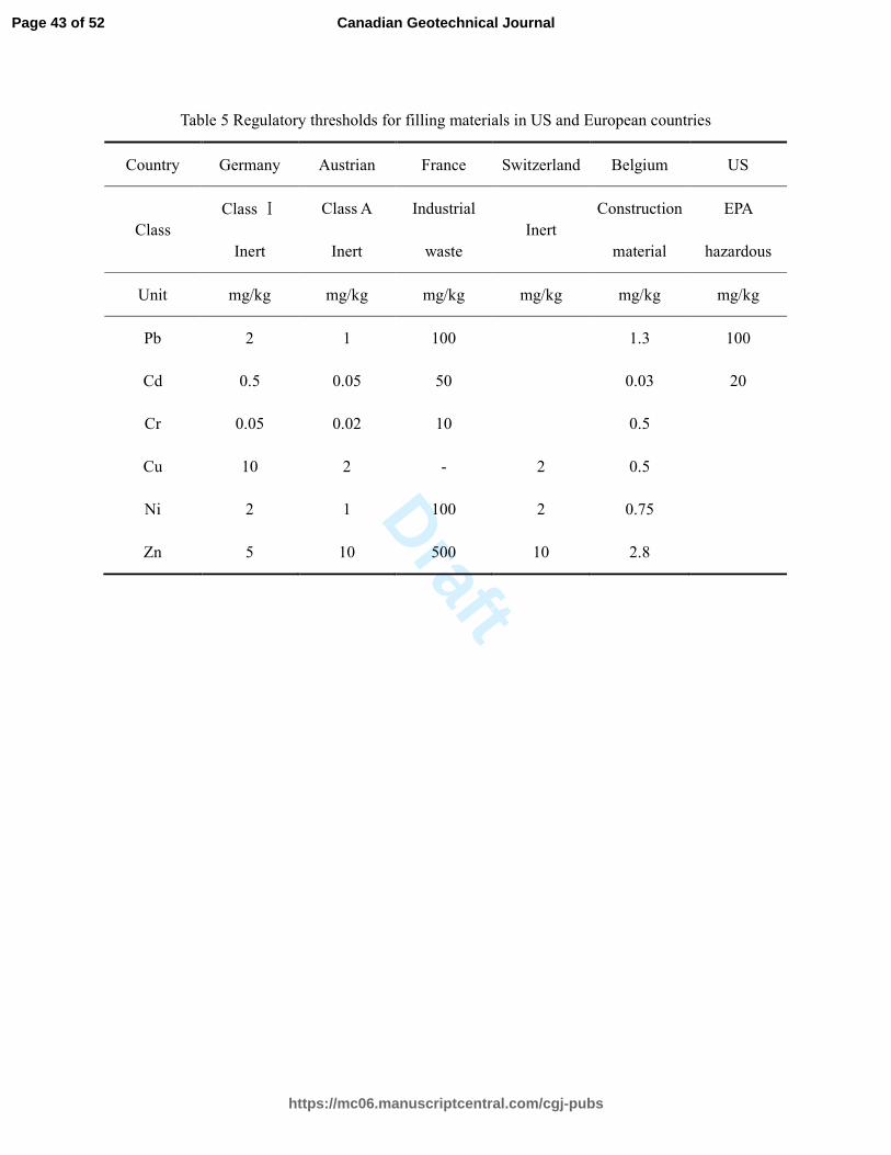
Draft
Table 5 Regulatory thresholds for filling materials in US and European countries
Country Germany Austrian France Switzerland Belgium US
Class Class Ⅰ
Inert
Class A
Inert
Industrial
waste Inert
Construction
material
EPA
hazardous
Unit mg/kg mg/kg mg/kg mg/kg mg/kg mg/kg
Pb 2 1 100 1.3 100
Cd 0.5 0.05 50 0.03 20
Cr 0.05 0.02 10 0.5
Cu 10 2 - 2 0.5
Ni 2 1 100 2 0.75
Zn 5 10 500 10 2.8
Page 43 of 52
https://mc06.manuscriptcentral.com/cgj-pubs
Canadian Geotechnical Journal
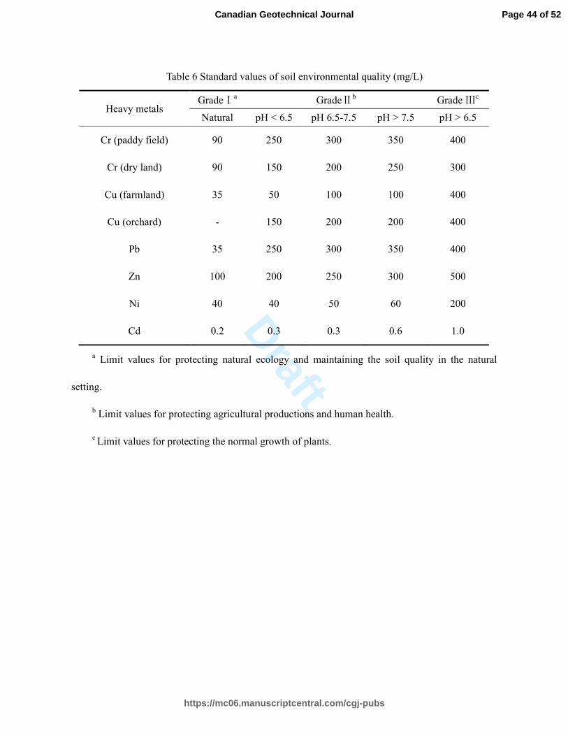
Draft
Table 6 Standard values of soil environmental quality (mg/L)
Heavy metals GradeⅠa GradeⅡb Grade Ⅲc
Natural pH < 6.5 pH 6.5-7.5 pH > 7.5 pH > 6.5
Cr (paddy field) 90 250 300 350 400
Cr (dry land) 90 150 200 250 300
Cu (farmland) 35 50 100 100 400
Cu (orchard) - 150 200 200 400
Pb 35 250 300 350 400
Zn 100 200 250 300 500
Ni 40 40 50 60 200
Cd 0.2 0.3 0.3 0.6 1.0
a Limit values for protecting natural ecology and maintaining the soil quality in the natural
setting.
b Limit values for protecting agricultural productions and human health.
c Limit values for protecting the normal growth of plants.
Page 44 of 52
https://mc06.manuscriptcentral.com/cgj-pubs
Canadian Geotechnical Journal

Draft
Table 7 Standard values of surface water environmental quality (mg/L)
Heavy metals Class Ⅰa Class Ⅱb Class Ⅲc Class Ⅳd Class Ⅴe
Cr ≤ 0.01 ≤ 0.05 ≤ 0.05 ≤ 0.05 ≤ 0.1
Cu ≤ 0.01 ≤ 1.0 ≤ 1.0 ≤ 1.0 ≤ 1.0
Pb ≤ 0.01 ≤ 0.01 ≤ 0.005 ≤ 0.005 ≤ 0.1
Zn ≤ 0.05 ≤ 1.0 ≤ 1.0 ≤ 2.0 ≤ 2.0
Cd ≤ 0.001 ≤ 0.005 ≤ 0.005 ≤ 0.005 ≤ 0.01
Ni
a Limit values for the source water and the national nature reserve.
b Limit values for the first-grade surface sources protection zones for domestic and drinking
water.
c Limit values for the secondary -grade surface sources protection zones for domestic and
drinking water.
d Limit values for the common process water and the human body non-direct contact
entertainment water .
e Limit values for agricultural water and general landscape water.
Page 45 of 52
https://mc06.manuscriptcentral.com/cgj-pubs
Canadian Geotechnical Journal

Draft
(a)
Control Pavement
Pavement with Solidified Fly Ash
(b)
Fig. 1 Finite element modeling of pavements with/without solidified fly ash: (a) Illustration of
Pavements with and without Solidified Fly Ash; (b) Example of Meshed Finite Element Model of
Pavement
Page 46 of 52
https://mc06.manuscriptcentral.com/cgj-pubs
Canadian Geotechnical Journal

Draft
Fig. 2. Grain size distribution curve for fly ash.
0 20 40 60 80 100
C1
C2C3
S4
C1
S4C3
B
S4
S4 BB
C1C1
C2: Calcite
S2: Silicon Chloride
S4
H:Halite
S4: Sylvite
Intensity (CPS)
2Theta (deg.)
C1
C1: Calcium Chloride Hydroxide
S2
H
B
B:Beryllium Palladium
C2
I
I:Iron Sulfide
S3
S3:StanniteA
A:Amesite-2H1
S1S1:Silver Aluminum Sulfide
C3:Calcium Chlorite Hydrate
L
L:Lead Bismuth Arsenate
P
P:Portlandite
Fig. 3. XRD analysis of fly ash.
1 0.1 0.010
20
40
60
80
100
Cumulative percentage (%)
Particle size (mm)
Fly ash in this study
S1
S2
S3
Page 47 of 52
https://mc06.manuscriptcentral.com/cgj-pubs
Canadian Geotechnical Journal

Draft
(a)
(b)
0
2
4
6
8
1028 days14 days7 days
9633 6396
Cement content: 10%
Cement content: 20%
Cement content: 30%
Cement content: 40%
Compressive strength (MPa)
Chelating agent content (%)
Freeze-thaw cycles: 5
9
(c)
0
2
4
6
8
10
96396396
28 days14 days7 days
Freeze-thaw cycles: 10 Cement content: 10%
Cement content: 20%
Cement content: 30%
Cement content: 40%
Compressive strength (MPa)
Chelating agent content (%)
3
Fig. 4 compressive strength of cement-based samples: (a) Standard curing condition; (b) 5
freeze-thaw cycles; (c) 10 freeze-thaw cycles.
0
2
4
6
8
10
969 3 3 6 96
28 days14 days
Compressive strength (MPa)
Chelating agent content (%)
Cement content: 10%
Cement content: 20%
Cement content: 30%
Cement content: 40%
Standard curing condition
7 days
3
Page 48 of 52
https://mc06.manuscriptcentral.com/cgj-pubs
Canadian Geotechnical Journal

Draft
(a)
(b)
(c)
Fig. 5 Secant modulus loss of cement-based samples: (a) 3% chelating agent; (b) 6% chelating
agent; (c) 9% chelating agent.
10 20 30 400
25
50
75
100
125Chelating agent: 3%
Secant modulus (MPa)
Cement content (%)
7 days, 5 cycles
14 days, 5 cycles
28 days, 5 cycles
7 days, 10 cycles
14 days, 10 cycles
28 days, 10 cycles
10 20 30 400
25
50
75
100
125Chelating agent: 6%
Secant modulus (MPa)
Cement content (%)
7 days, 5 cycles
14 days, 5 cycles
28 days, 5 cycles
7 days, 10 cycles
14 days, 10 cycles
28 days, 10 cycles
10 20 30 400
25
50
75
100
125Chelating agent: 9%
Secant modulus (MPa)
Cement content (%)
7 days, 5 cycles
14 days, 5 cycles
28 days, 5 cycles
7 days, 10 cycles
14 days, 10 cycles
28 days, 10 cycles
Page 49 of 52
https://mc06.manuscriptcentral.com/cgj-pubs
Canadian Geotechnical Journal
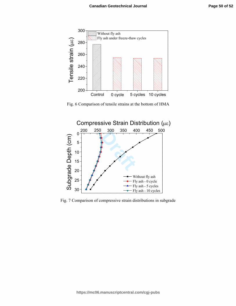
Draft200
220
240
260
280
300
5 cycles 10 cycles0 cycle
Tensile strain (µε)
Without fly ash
Fly ash under freeze-thaw cycles
Control
Fig. 6 Comparison of tensile strains at the bottom of HMA
Fig. 7 Comparison of compressive strain distributions in subgrade
500450400350300200
Subgrade Depth (cm)
Without fly ash
Fly ash - 0 cycle
Fly ash - 5 cycles
Fly ash - 10 cycles
250
Compressive Strain Distribution (µε)
0
5
10
15
20
25
30
Page 50 of 52
https://mc06.manuscriptcentral.com/cgj-pubs
Canadian Geotechnical Journal

Draft
(a)
(b)
(c)
Fig. 8 Heavy metals leachability: (a) 7-day curing; (b) 14-day curing; (c) 28-day curing.
0.0
0.2
0.4
0.6
0.8
1.0
1.2
96396396396396396
CdNiZnPbCu
Leachability (mg/L)
Chelating agent content (%)
Cement content: 10%
Cement content: 20%
Cement content: 30%
Cement content: 40%
7 daysCr
3
0.0
0.2
0.4
0.6
0.8
1.0
1.2CdNiZnPbCuCr
96396396396396396
Cement content: 10%
Cement content: 20%
Cement content: 30%
Cement content: 40%
Leachability (mg/L)
Chelating agent content (%)
14 days
3
0.0
0.2
0.4
0.6
0.8
1.0
1.2
3 9639639639639639
CdNiZnPbCuCr
Cement content: 10%
Cement content: 20%
Cement content: 30%
Cement content: 40%
Leachability (mg/L)
Chelating agent content (%)
28 days
6
Page 51 of 52
https://mc06.manuscriptcentral.com/cgj-pubs
Canadian Geotechnical Journal

Draft
Fig. 9 The bonding sites of chelating agent for heavy metal S/S
Page 52 of 52
https://mc06.manuscriptcentral.com/cgj-pubs
Canadian Geotechnical Journal