use of compliant hinges to tailor flight dynamics of...
TRANSCRIPT

Use of Compliant Hinges to Tailor FlightDynamics of Unmanned Aircraft
Emily A. Leylek∗ and Mark Costello†
Georgia Institute of Technology, Atlanta, Georgia 30332
DOI: 10.2514/1.C033056
The nexus of advanced manufacturing methods, computer-aided design tools, and modern structural-analysis
software has enabled the design and fabrication of structurally complex wing structures with unique features. This is
particularly true for small unmanned aircraft, in which discrete structural hinges can easily be integrated into the
overall vehicle design. This paper examines the use of discrete structural hinges for tailoring the low-frequency flight
dynamics of the vehicle. For sufficiently soft discrete structural hinges, substantial couplingbetween flexible and rigid
modes occurs, leading to the potential to modify the flight dynamic behavior through structural flexibility. Using a
multibody flight dynamics simulation tool with a nonlinear lifting-line aerodynamic representation, different
structural-hinge elastic properties, orientation, and location on the aircraft are examined. The results for a small
unmanned aircraft indicate that flexibility mostly affects the longitudinal modes and associated handling qualities of
the vehicle. Changes in the short-period and phugoid modes due to flexibility caused by a set of discrete structural
hinges are often antagonistic. A structural-hinge stiffness above a certain critical value tends to improve short-period
flying qualities; below this value, the short-period flying qualities degrade. In addition to the stiffness characteristics
of the discrete structural hinge, orientation of the hinge has a significant effect on flight dynamics. Orienting the
structural hinge to produce pitch–flap coupling can triple the short-period-mode damping, which could improve a
nominally Level 3 rated aircraft to a Level 1 rated aircraft.
Nomenclature
�αP∕Q = angular acceleration of body P with respect toreference frame Q, rad∕s2
�a�B∕I = acceleration of center of gravity of bodyBwithrespect to inertial reference frame, m∕s2
CB = component operator in generic referenceframe B
CL, CD = lift coefficient, drag coefficient [nd]Cl, Cm, Cn = roll, pitch, yaw aerodynamic moment co-
efficients in fuselage body reference frame[nd]
CL0, CD0
= lift coefficient, drag coefficient at zero angle ofattack [nd]
CLs , CYs , CDs = lift, side force, drag aerodynamic forcecoefficient derivatives with respect to variables [nd]
Cls ,Cms , Cns = roll, pitch, yaw aerodynamic moment co-efficient derivatives with respect to variables [nd]
CX, CY , CZ = aerodynamic force coefficients in the fuselagebody reference frame [nd]
FLH, FRH = left-hinge, right-hinge joint constraint forces, Ng = acceleration due to gravity, m∕s2�H�B∕I = angular momentum about center of gravity of
bodyBwith respect to inertial reference frame,kg · m2∕s
I = mass moment of inertia matrix, kg · m2
�IF, �JF, �KF = basis vectors for fuselage body reference frame�II , �JI , �KI = basis vectors for inertial reference frame
�IL, �JL, �KL = basis vectors for left-wing body referenceframe
�ILF, �JLF, �KLF = basis vectors for left-fuselage-hinge jointreference frame
�ILH, �JLH, �KLH = basis vectors for left-hinge-wing jointreference frame
MLH,MRH = left-hinge, right-hinge joint constraint mo-ments, N · m
m = mass, kgp, q, r = angular-velocity measure numbers in body
reference frame, rad∕sQd �P∕dt = time derivative of vector P with respect to the
Q reference frame�rLH→�L = position vector from left-hinge position to left-
wing center of gravity, m�rO→�F = positionvector fromorigin of inertial reference
frame to center of gravity of fuselage, m�r�F→LH = position vector from center of gravity of
fuselage to left-hinge position, mSB = skew symmetric cross-product operator in
generic reference frame BSω = skew symmetric cross-product operator acting
on angular ratesu, v, w = velocity-vector measure numbers in body
reference frame, m∕sui, vi, wi = components of induced velocity vector, m∕su∞, v∞, w∞ = components of freestream velocity vector,m∕s�V�B∕I = velocity of center of gravity of body B with
respect to inertial reference frame, m∕s�V∞, V∞ = freestream velocity vector, magnitude of
freestream velocity vector, m∕sx, y, z = position-vector measure numbers in inertial
reference frame, mα, β = angle of attack, sideslip angle, radβL, βR = left-wing, right-wing flap angle about the
hinge axis, radΓ = dihedral angle, radΓp = circulation strength of panel horseshoe vortex,
m2∕sδLE, δRE, δR = left-elevon deflection, right-elevon deflection,
rudder deflection, rad�ε = downwash, or induced velocity, vector, m∕sζ = damping ratio, [nd]
Received 30 June 2014; revision received 20 December 2014; accepted forpublication 20 December 2014; published online 20 April 2015. Copyright ©2014 by the American Institute of Aeronautics and Astronautics, Inc. Allrights reserved. Copies of this paper may be made for personal or internal use,on condition that the copier pay the $10.00 per-copy fee to the CopyrightClearance Center, Inc., 222 Rosewood Drive, Danvers, MA 01923; includethe code 1533-3868/15 and $10.00 in correspondence with the CCC.
*Graduate Student, Guggenheim School of Aerospace Engineering.Student Member AIAA.
†David S. Lewis Professor of Autonomy, Guggenheim School ofAerospace Engineering, Woodruff School of Mechanical Engineering.Associate Fellow AIAA.
AIAA Early Edition / 1
JOURNAL OF AIRCRAFT
Dow
nloa
ded
by G
EO
RG
IA I
NST
OF
TE
CH
NO
LO
GY
on
Sept
embe
r 28
, 201
5 | h
ttp://
arc.
aiaa
.org
| D
OI:
10.
2514
/1.C
0330
56

ρ∞ = freestream density, kg∕m3
ϕ, θ, ψ = Euler angle rotation parameters, radωn = natural frequency, rad∕s�ωP∕Q = angular velocity of body P with respect to
reference frame Q, rad∕s
Subscripts
F = fuselage bodyL = left-wing bodyR = right-wing body� = center of gravity
I. Introduction
A DVANCES in manufacturing methods now allow complexmultimaterial structures to be constructed cost effectively [1–3].
These new manufacturing techniques make it possible to creatediscrete joints of compliant material with particular desirablestiffness and damping characteristics incorporated into a larger, rigidstructure. This is especially practical in the fabrication of micro- andsmall-unmanned-aircraft systems [4–6]. Introducing flexibility intothe wing of a small unmanned aircraft via a chordwise discreterevolute hinge can be used to alter the dynamics of the aircraft. Thisincludes the low-frequency flight dynamic modes, such as the short-period, phugoid, roll, Dutch roll, and spiral modes.A discrete structural hinge can be used as a design tool to shape the
flight dynamic characteristics much like wing dihedral, twist, etc., isused. Numerous authors have considered wing flexibility in thecontext of flight dynamics. Passive articulation systems on aircrafthave been shown to reduce gust sensitivity [7,8]. Porter and Brown[9] studied aircraft equippedwith a freewing,which allowed pitchingabout a spanwise axis ahead of the aerodynamic center of the wing.They found that such a wing reduced disturbances from gusts andimproved handling qualities [9]. Birds and insects are known toexploit the compliancy in their joints to achieve desirable wingmotion, which reduces energy consumption [2,10,11]. Krus [11]showed how flexible spanwise hinges or chordwise compliant jointswith swept joint axes stabilize tailless birdlike aircraft. Rotorcrafthave long used such a hinge, denoted as a δ3 hinge, for pitch–flapcoupling of blades to reduce the pitch of the blade as it flaps [12]. Asfar back as 1928, Waterman [13] proposed an aircraft with hingedwings with δ3 orientations that would reduce the incidence angle asthe wing flapped due to wind gusts and heavy turbulence. The wingswere connected to the fuselage by a pneumatic system that wouldact both as a shock absorber and as ameans to set the configuration ofthewings for different phases of flight [13]. Aeroelastic tailoring usesthe plies in composite structures to angle the bending axis forward oraft, similar to δ3 orientations, to introduce cross-coupling betweenbending and twisting of the structure. This produceswash-in orwash-out on the wing, which can be used to passively control flutter onset,divergence, induced drag, lift effectiveness, control effectiveness,and/or maneuver load relief [14,15]. Pitt conducted static anddynamic aeroelastic design studies using a physical, elastic δ3 hingeof various orientations and stiffnesses to createwash-in andwash-outthat affected flutter characteristics and divergence speeds similar toaeroelastic tailoring with composites [16].Ameri et al. conducted a study of the dynamic response of a flying
wing with articulated winglets and showed how dynamic modeschange as the vehicle is trimmed through varying symmetric dihedralangles for two winglet sizes [17]. A series of papers by Abdulrahimand Lind [18–20] investigated symmetric variable gull-wingmorphing in simulation and flight tests. Thevariable gull wing is usedas a slow control effector to deform between flight modes and tochange the glide ratio, climb performance, and stall characteristics.The effect of different gull angles on the dynamic modes of thevehicle is also shown [18–20]. A gull-wing aircraft with a hinge tocontrol the outboard wing sweep used the change in wing sweep tovary the static margin and longitudinal handling qualities [21].Paranjape et al. used bifurcation analysis to investigate symmetric
and asymmetric dihedral on an articulated wing aircraft, and theeffect on stability [22].In a subsequent paper, Paranjape et al. extended this work to an
articulated aircraft with flexible wings and found that moderatelyflexible wings with a Young’s modulus on the order of magnitude of10 and higher did not substantially affect the stability of the vehicle incoordinated turning flight, although highly flexible wings couldimprove turning performance [23]. Babcock and Lind [24] studiedhow changes in bending stiffness and torsional stiffness of a flexiblewing on a micro air vehicle affect the rigid-body modes. Theydiscovered that the torsional stiffness had little effect on rigid-bodymodes, but the bending stiffness caused large changes in dihedral andthe state of the vehicle in trim, significantly affecting the lateralmodes of the vehicle [24]. Numerous other studies have investigatedthe coupling between rigid-body modes and structural modesbrought on by flexible wings and methods for approximating thechanges in rigid-body dynamics from this coupling [25–31]. Severalstudies tie these changes in the rigid modes from flexibility tochanges in the handling qualities, showing that highly elasticairframes have degraded flying qualities compared to their rigidcounterparts [32–34].This paper builds on the previous work on the stability of
articulated wing aircraft and flexible aircraft. Unlike the currentliterature on flexible aircraft wherein the entire wing is assumed to beelastic, this work focuses on wing articulation provided by a discretecompliant hinge formed by new multimaterial fabrication processes.Changes in traditional rigid-body dynamic modes of the vehicle areexamined as a function of stiffness and damping of discrete structuralhinges. Rather than allowing the wings to displace to their naturalequilibrium dihedral in different flight conditions, the dihedral angleis forced to be equivalent in all cases to isolate the effects of hingeproperties on the flight dynamics of the vehicle. The effect of δ3 hingeorientations (pitch–flap coupling) is extended to fixed-wing aircraftstability analysis, and a δ2 hinge orientation (sweep–flap coupling) isalso introduced. The hinge location, either where it connects the rootof thewing to the fuselage or its location spanwise on thewing, is alsoconsidered. The sensitivity of flight dynamicmodes to changes in theelastic configuration is examined via static aeroelastic analysis. Also,changes in the dynamics of the vehicle are correlated to handling-qualities ratings to show how the design parameters of a flexiblehinge can be used to tailor the flying qualities of the vehicle. Exampleresults are shown for a nominal small unmanned aircraft.
II. Simulation Methodology
A compliant hinge embedded in a wing structure throughmultimaterial fabrication permits the wing to articulate relative to thefuselage through large, time-varying angles. As such, prediction ofthe performance of this physical mechanism requires a multibodysimulation to incorporate the dynamics of this relative motion.
A. Aircraft Geometry
Each wing is attached to the fuselage with a revolute joint, addingone degree of freedom (DOF) perwing to the standard six-DOF rigid-body aircraft model. The system is composed of three bodies(fuselage, left wing, and right wing) with a total of eight DOF. Eachbody has a body reference frame with the origin located at the bodycenter of gravity (c.g.). A frame aligned with the joint is also definedat the joint on each body. A schematic of the dynamic system isdepicted in Fig. 1. The transformation between the inertial frame andthe body frame of the fuselage is given in Eq. (1). Euler angles areused for this transformation matrix, Eq. (2). Equations (3–5) definethe rotations between the body frames of the system. The rotationmatrix TβL is the rotation through the flap angle, βL, of the wingrelative to the fuselage about the joint axis, given in Eq. (6).8<
:�IF�JF�KF
9=; � �TFI �
8<:
�II�JI�KI
9=; (1)
2 AIAA Early Edition / LEYLEK AND COSTELLO
Dow
nloa
ded
by G
EO
RG
IA I
NST
OF
TE
CH
NO
LO
GY
on
Sept
embe
r 28
, 201
5 | h
ttp://
arc.
aiaa
.org
| D
OI:
10.
2514
/1.C
0330
56

�TFI � �
24 cos θ cos ψ cos θ sin ψ − sin θ
sin ϕ sin θ cos ψ − cosϕ sinψ sin ϕ sin θ sin ψ � cos ϕ cos ψ sin ϕ cos θcos ϕ sin θ cos ψ � sin ϕ sin ψ cos ϕ sin θ sin ψ − sin ϕ cos ψ cos ϕ cos θ
35 (2)
8<:
�ILF�JLF�KLF
9=; � �TLF�
8<:
�IF�JF�KF
9=; (3)
8<:
�ILH�JLH�KLH
9=; � �TβL �
8<:
�ILF�JLF�KLF
9=; (4)
8<:
�IL�JL�KL
9=; � �TLH�T
8<:
�ILH�JLH�KLH
9=; (5)
�TβL � �
24 1 0 0
0 cos�βL� sin�βL�0 − sin�βL� cos�βL�
35 (6)
Equation (7) defines the complete transformation matrix, TL, fromthe fuselage body frame to the left-wing body frame. Figure 2 depictsthe relations between all of the reference frames and transformationsbetween them. The rotation angles between frames are noted abovethe arrows connecting the frames, and the transformation matrixdesignations are noted below the arrows in the figure.
TL � TTLHTβLTLF (7)
The state vectorX of the system is given in Eq. (8). Definitions forthese state variables follow in Eqs. (9–11). The position, attitude,velocity, and angular-velocity variables are defined for the fuselagebody c.g. In addition, the variables βL and βR are the flap rotationsabout the joint axis for the left and right wings, respectively.
X��x y z ϕ θ ψ uF vF wF pF qF rF βL _βL βR _βR �T (8)
�rO→�F � x �II � y �JI � z �KI (9)
�V�F∕I � uF �IF � vF �JF �wF �KF (10)
�ωF∕I � pF �IF � qF �JF � rF �KF (11)
B. Kinematic Equations of Motion
The eight-DOF simulation model uses the body-framecomponents of the fuselage mass-center velocity and angular-velocity vectors rather than inertial-frame measure numbers. Theposition states are defined in the inertial frame. Kinematic differentialequations relate the time derivatives of “position” coordinates to“velocity” coordinates. The kinematic differential equations relatingtime derivatives of the mass-center position-vector components withthemass-center velocity in the body frame are provided inEq. (12). Ina similar manner, time derivatives of the Euler orientation angles arerelated to the body-frame angular velocities through Eq. (13).8<
:_x_y_z
9=; � �TFI �T
8<:uFvFwF
9=; (12)
8<:
_ϕ_θ_ψ
9=; �
"1 sin ϕ tan θ cos ϕ tan θ0 cos ϕ − sin ϕ0 sin ϕ sec θ cos ϕ sec θ
#(pFqFrF
)(13)
C. Dynamic Equations of Motion
Using aNewton–Euler approach to form the dynamic equations ofmotion, the translational and rotational dynamic equations of motionare developed for each of the three bodies (fuselage, left wing, andright wing) separately. The Newton–Euler translational dynamicequations of motion for a general body B are provided in Eq. (14).Likewise, the general body rotational dynamic equations areprovided in Eq. (15). For the fuselage body, the vector-derivativetransport theorem is used to determine the acceleration and angularmomentum in the body frame, Eqs. (15) and (16), respectively. Thesuperscript in front of a derivative term denotes the reference frame.Forces on the fuselage include weight, aerodynamics, propulsivethrust, and joint constraints. Moments on the fuselage about itsc.g. include aerodynamics, propulsive torque, elastic stiffness anddamping, and joint constraints.
Fig. 1 Articulated wing aircraft model.
Fig. 2 Frames involved in simulation with rotation angles and transfor-mation matrices between them.
AIAA Early Edition / LEYLEK AND COSTELLO 3
Dow
nloa
ded
by G
EO
RG
IA I
NST
OF
TE
CH
NO
LO
GY
on
Sept
embe
r 28
, 201
5 | h
ttp://
arc.
aiaa
.org
| D
OI:
10.
2514
/1.C
0330
56

mB �a�B∕I � �F (14)
Id �H�B∕Idt
� �M� (15)
�a�F∕I �Id �V�F∕I
dt�
Fd �V�F∕Idt
� �ωF∕I × �V�F∕I
�
8><>:
_uF
_vF
_wF
9>=>;�
8><>:pF
qF
rF
9>=>; ×
8><>:uF
vF
wF
9>=>; (16)
Id �H�F∕Idt
�Fd �H�F∕I
dt� �ωF∕I × �H�F∕I
� IF
8><>:
_pF
_qF
_rF
9>=>;�
8><>:pF
qF
rF
9>=>; × IF
8><>:pF
qF
rF
9>=>; (17)
For the wing equations of motion, all velocity, angular-velocity,acceleration, and angular-acceleration terms are written in terms ofthe state variables, rather than each body’s individual velocity andacceleration terms. To obtain the acceleration of the wing c.g., thekinematic relationship of the accelerations of two points fixed on arigid body is applied to thewing, Eq. (18), and the fuselage, Eq. (19).Shorthand for position, velocity, and angular-velocity components isintroduced in Eqs. (20–24). The components of acceleration of thewing c.g. are written in the wing body frame, so terms in the fuselagebody frame are transformed using thematrix relating the fuselage andwing frames, given in Eq. (7). Using that transformation along withthe defined shorthand notation and substituting Eq. (19) into Eq. (18),the components of acceleration of the wing are provided in Eq. (25).The right-wing equations follow analogously to the left-wingequations given.
�a�L∕I � �aLH∕I � �ωL∕I × �ωL∕I × �rLH→�L � �αL∕I × �rLH→�L (18)
�aLH∕I � �a�F∕I � �ωF∕I × �ωF∕I × �r�F→LH � �αF∕I × �r�F→LH (19)
rL � CF��r�F→LH� (20)
rLL � CL� �rLH→�L � (21)
VF �
8><>:uF
vF
wF
9>=>;; ωF �
8><>:pF
qF
rF
9>=>;;
_VF �
8><>:
_uF
_vF
_wF
9>=>;; _ωF �
8><>:
_pF
_qF
_rF
9>=>; (22)
SVF � SF�VF� �"
0 −wF vFwF 0 −uF−vF uF 0
#(23)
SωF � SF�ωF�; SL � SF�rL�; SLL � SL�rLL� (24)
aL � TTLHTβLTLF� _VF � SωFVF − SL _ωF � SωFSωF rL� − SLL _ωL� SωLSωLrLL (25)
The preceding equation requires knowledge of the angular velocityand angular acceleration of the wing. Kinematic relationships can beused to define these in terms of the state variables, Eqs. (26–28).Again, all terms are transformed to thewing body frame. These termsare also used in the derivative of angular momentum in the derivationof the rotational dynamic equations of motion for the wing. Thederivative of angular momentum of the left wing is provided inEq. (29), written in component form in Eq. (30).
�ωL∕I � �ωL∕F � �ωF∕I (26)
ωL � TTLHTβLTLFωF � TTLHΛ_βL (27)
αL � _ωL � TTLHTβLTLF _ωF � TTLHΛ�βL � TTLH _TβLTLFωF (28)
Id �H�L∕Idt
�Ld �H�L∕I
dt� �ωL∕I × �H�L∕I (29)
CL
�Id �H�L∕Idt
�� IL _ωL � SωL ILωL (30)
Thewing forces includeweight, aerodynamics, and joint constraints.Thewingmoments about the body c.g. include aerodynamics, elasticstiffness and damping, and joint constraints. TheΛ andΦmatrices ofEq. (31) select the appropriate component of the flapping angular-velocity vector and joint constraint moments, respectively.
Λ �"1
0
0
#; Φ �
"0 0
1 0
0 1
#(31)
The translational and rotational dynamic equations of motion for allthree bodies then yield the six equations in component form,Eqs. (32–37).
mF� _VF � SωFVF� � FFAERO� FTHRUST � FFGRAV
� FLH � FRH
(32)
IF _ωF � SωF IFωF � MFAERO�MTORQUE − TTLFΛMLELASTIC
− TTLFΛMRELASTIC�MLH �MRH (33)
4 AIAA Early Edition / LEYLEK AND COSTELLO
Dow
nloa
ded
by G
EO
RG
IA I
NST
OF
TE
CH
NO
LO
GY
on
Sept
embe
r 28
, 201
5 | h
ttp://
arc.
aiaa
.org
| D
OI:
10.
2514
/1.C
0330
56

mLTL� _VF � SωFVF − SL _ωF � SωFSωF rL� −mLSLL _ωL�mLSωLSωLrLL � FLAERO
� FLGRAV− TLFLH (34)
IL _ωL�SωL ILωL�MLAERO�TTLHΛMLELASTIC
−TLΦLMLH
−TLSLFLH (35)
mRTR� _VF � SωFVF − SR _ωF � SωFSωF rR� −mRSRR _ωR�mRSωRSωRrRR � FRAERO
� FRGRAV− TRFRH (36)
IR _ωR � SωRIRωR � MRAERO� TTRHΛMRELASTIC
− TRΦRMRH
− TRSRFRH (37)
The constraint forces and moments at the joints are of interest tomonitor during the simulation, so they are retained in the dynamicequations rather than being algebraically eliminated. This creates amatrix equation consisting of 18 equations and 18 unknowns given inEqs. (38–45), which is solved for the state derivative vector requiredfor numerical simulation, as well as the joint constraint forces andmoments.
�A�
8>>>>>>>>>>><>>>>>>>>>>>:
_VF_ωF�βL�βRFLH
FRH
MLH
MRH
9>>>>>>>>>>>=>>>>>>>>>>>;
�
8>>>>>><>>>>>>:
B1
B2
B3
B4
B5
B6
9>>>>>>=>>>>>>;
(38)
in which
A �
26666664
mFI3×3 0 0 0 −I3×3 −I3×3 0 0
0 IF 0 0 −SL −SR ΦL ΦR
mLTL −mLTLSL −mLSLLTL −mLSLLTTLHΛL 0 TL 0 0 0
0 ILTL ILTTLHΛL 0 TLSL 0 TLΦL 0
mRTR −mRTRSR −mRSRRTR 0 −mRSRRTTRHΛR 0 TR 0 0
0 IRTR 0 IRTTRHΛR 0 TRSR 0 TRΦR
37777775
(39)
B1 � −mFSωFVF � FF (40)
B2 � −SωF IFωF �MF (41)
B3 � −mLTL�SωFVF � SωFSωF rL� �mLSLLTTLH _TβLTLFωF
−mLSωLSωLrLL � FL (42)
B4 � −ILTTLH _TβLTLFωF − SωL ILωL �ML (43)
B5 � −mRTR�SωFVF � SωFSωF rR� �mRSRRTTRH _TβRTRFωF
−mRSωRSωRrRR � FR (44)
B6 � −IRTTRH _TβRTRFωF − SωR IRωR �MR (45)
The �A�matrix in Eqs. (38) and (39) is a square 6 × 6 block matrix, inwhich each block consists of a 3 × 3 matrix. The Bmatrix is a 6 × 1block vector, in which each element consists of three rows.
D. Applied Loads
In the preceding dynamic equations of motion, the total externallyapplied forces and moments about the mass center in the individualbody reference frame appear, such as FF and MF for the fuselagebody, andFL andML for the left wing. These terms do not include theconnection constraint loads, but are comprised of the forces andmoments due to gravity, aerodynamics, propulsion, and jointelasticity. The propulsive force and moment consist of the thrust andtorque generated by the propulsive system.
1. Elastic Loads
The compliant hinge is modeled as a linear rotational spring anddamper, generating a moment about the hinge axis when the flapangle of thewing is deflected from the zero-load rotation angle of thespring β0. This moment is applied equally and opposite between thefuselage and wing bodies. The component of the elastic moment inthe joint frame is given in Eq. (46), in which k is the spring stiffnessand c is the damping coefficient.
MLELASTIC� −k�βL − β0� − c_βL (46)
2. Aerodynamic Loads
Aerodynamic loads on the aircraft are computed usingsuperposition. In the preceding equations ofmotion, the aerodynamicforces and moments are determined for each body individually. Forthe fuselage body, which consists of the fuselage, vertical tail, andhorizontal tail, a stability-derivative formulation is employed. For the
left and right wings, a nonlinear lifting-line approach is used. Bothmodels are described as follows.Analytical stability derivatives are used for the fuselage, as well as
analytical estimates for the conventional control derivatives. The liftand drag forces, Eqs. (47) and (48), respectively, are determined bythe lift and drag on the fuselage, vertical tail, and horizontal tail. InEq. (48), e is Oswald’s efficiency factor, and is the tail aspect ratio.The first three terms of the drag model, Eq. (48), represent the two-dimensional (2-D) airfoil drag from the tail lifting surface. Thefuselage drag is also included in the first term, CD0. The fourth term,which is dependent on the square of the lift coefficient, adds the three-dimensional finite wing, or induced drag, effects. The side-forcecoefficient is given in Eq. (49). The lift and drag forces are rotatedthrough the angle of attack to transform them to the body frame,Eq. (50). The coefficients of roll, pitch, and yaw moments arepresented in Eqs. (51–53). The body-frame forces and moments are
AIAA Early Edition / LEYLEK AND COSTELLO 5
Dow
nloa
ded
by G
EO
RG
IA I
NST
OF
TE
CH
NO
LO
GY
on
Sept
embe
r 28
, 201
5 | h
ttp://
arc.
aiaa
.org
| D
OI:
10.
2514
/1.C
0330
56

calculated from the coefficients using Eq. (54), in which S is thewingarea, b is the wingspan, and �c is the mean aerodynamic chord.
CL � CL0� CLα
α� CLδLEδLE � CLδRE
δRE (47)
CY � CYββ� CYpp̂� CYr r̂� CYδR
δR (49)
(CXCYCZ
)�"cos�α� 0 − sin�α�
0 1 0
sin�α� 0 cos�α�
#(−CDCY−CL
)(50)
Cl � Clβ β� Clp p̂� Clr r̂� ClδLE δLE � ClδRE δRE � ClδR δR (51)
Cm � Cm0� Cmα
α� Cmq q̂� CmδLEδLE � CmδLE
δLE (52)
Cn � Cnβ β� Cnp p̂� Cnr r̂� CnδLE δLE � CnδRE δRE � CnδR δR(53)
8>>>>>><>>>>>>:
XYZLMN
9>>>>>>=>>>>>>;� 1
2ρ∞V
2∞S
8>>>>>><>>>>>>:
CXCYCZbCl�cCmbCn
9>>>>>>=>>>>>>;
(54)
The aerodynamic loads on each wing are calculated using anumerical lifting-linemethod, as detailed in [35]. Thewing is dividedinto spanwise stations, forming panels, as depicted in Fig. 3. A nodepoint is placed at the quarter chord of each station. Each panel has ahorseshoe vortex with circulation strength of Γp. The bound portionof the horseshoe vortex is placed along the quarter chord connectingthe node points. The trailing vortices of the horseshoe vortex arealigned with the freestream velocity direction. A control point isplaced on each panel at the quarter chordmidwaybetween nodes. Thedownwash at an arbitrary control point from any horseshoe vortex isobtained using the Biot–Savart law. The vectors �r1 and �r2 are defined
from each node point of a horseshoe vortex to the control point.Notation for the magnitudes of these vectors is provided in Eq. (55).The total downwash at the control point from the horseshoe vortexcan be written by summing the downwash contribution from eachvortex filament of the horseshoe, Eq. (56). It is of note that a boundvortex does not produce downwash along its length, and the secondterm in the brackets of this equation, which is the downwashcontribution from the bound vortex, will produce a singularity when�r1 and �r2 are collinear and opposite directions. This is the case inFig. 4, when the control point investigated is on the same panel as thehorseshoe vortex. In such cases, Eq. (57) must be used to avoid thesingularity. The effective angle of attack that determines the lift onthe local airfoil section is found from Eq. (58). It is important to notethat the freestream velocity components in this equation includeaerodynamic velocity imparted by the motion of the body andatmospheric wind, if any exists. The induced velocity components inEq. (58) are described in the local-airfoil-section body frame.However, Eqs. (56) and (57) are easiest to compute with the vectorsexpressed in the inertial frame. Equation (59) relates the inertial-frame downwash-vector components to the local-frame downwashcomponents.
r1 � k �r1k; r2 � k �r2k (55)
�ε�Γp4π
��V∞× �r2
r2�r2− �V∞ · �r2�� �r1�r2�� �r1× �r2�r1r2�r1r2� �r1 · �r2�
−�V∞× �r1
r1�r1− �V∞ · �r1�
�(56)
�ε �Γp4π
��V∞ × �r2
r2�r2 − �V∞ · �r2�−
�V∞ × �r1
r1�r1 − �V∞ · �r1�
�(57)
αe � tan−1�w∞ − wiu∞ � ui
�(58)
(uiviwi
)� TTIBCI��ε� (59)
The calculation to include the wake into the contribution toaerodynamic loads from lifting surfaces does not have a closed-form solution for arbitrary configurations. An iterative, numericalapproach is adopted [36,37]. An initial spanwise downwashdistribution is assumed at all control points. Using this initialdownwash, the lift, drag, and pitching moment are calculated at eachpanel using 2-D airfoil data. From the panel lift, the circulationstrength of the horseshoe vortex at each panel is calculated usingEq. (60), in which L 0p is the sectional lift, cl is the sectional liftcoefficient, and �cp is themean aerodynamic chord of the panel. Using
V∞
Γp
Fig. 3 Spanwise panels and example horseshoe vortex for numericallifting-line method.
Node 1
Control Point
Node 2
1r
2r∞V
∞Vε
Fig. 4 Influence of horseshoe vortex on control point.
6 AIAA Early Edition / LEYLEK AND COSTELLO
Dow
nloa
ded
by G
EO
RG
IA I
NST
OF
TE
CH
NO
LO
GY
on
Sept
embe
r 28
, 201
5 | h
ttp://
arc.
aiaa
.org
| D
OI:
10.
2514
/1.C
0330
56

Eqs. (56) and (57), the downwash contribution from every horseshoevortex on each control point is calculated and summed to compute anew downwash distribution. The new distribution is compared to theprevious, and if the difference is within the specified convergencecriteria, the solution is considered to be converged. Otherwise, thenewly calculated distribution is damped, as in Eq. (61), and used asthe initial distribution, and the process iterates until convergence isachieved [36,37]. Once convergence is reached, the induced angle ofattack is calculated at each station, which is then used to obtain theeffective angle of attack. With knowledge of the 2-D airfoil, thesection lift, drag, and pitching moment of each panel are obtained.The contribution of each panel to the aerodynamic forces andmoments about the wing c.g. in the body frame is then summed overall the panels on the wing.
Γp �L 0p
ρ∞V∞� 1
2V∞ �cpcl (60)
�εinput � �εold � ζ��εnew − �εold� (61)
E. Flying-Quality Analysis
Linear dynamic models of the aircraft system are generated fromthe nonlinear equations of motion about a steady, level-flightcondition using small perturbation theory [38]. The linear models areused to perform modal analysis. The ability of an aircraft to performvarious categories of missions and the phases of flight composing themission without undue stress on the operator are measured by theflying-qualities criteria defined in MIL-F-8785C [39]. These criteriaare determined from the natural frequency and damping of the low-frequency flight dynamic modes of the vehicle.In the military specifications, the short-period-mode flying
qualities are also quantified by the parameters acceleration sensitivityand control anticipation parameter (CAP). The accelerationsensitivity ηα is the normal load factor per unit angle of attack ofthe vehicle, which is generally a fixed quantity for an aircraft notrelated to the dynamic response, since it only depends on the weightand lift-curve slope of the vehicle. The CAP uses the naturalfrequency of the short-period mode in its formulation.
ηα �CLα
CW(62)
CAP �ω2nSP
ηα(63)
To elucidate how compliant hinges change the flight dynamic modesof thevehicle, the changes in the aerodynamic stability derivatives areinvestigated using static aeroelasticity analysis, such as that describedin [40]. Assuming quasi-static wing flapping, the flap rates, _βL and_βR, and acceleration are zero, and the flap angles βL and βR can bedetermined from the linear model in terms of the other state variables.These can then be substituted into the numerically calculatedaerodynamic stability derivatives to determine the effect of flexibilityon the stability derivatives that significantly contribute to thetraditional dynamic modes of the vehicle. For the short-period mode,the modal natural frequency is largely determined by the stabilityderivatives Mw, Zw, and Mq. These terms are all negative and willincrease the natural frequency of the mode as their magnitudesincrease. The stability derivatives Zw and Mq contribute to thedamping of the short-period mode, increasing the damping as theybecomemore negative. The natural frequency of the phugoid is mostaffected by Zu, which increases the natural frequency as it becomesmore negative. The damping of the mode is affected by Xu, withdamping increased by more negative values of Xu, as well as thenatural frequency of themode. In the longitudinalmodes, increases in
the natural frequency of a mode will reduce the mode damping. Theroll mode, which is nonoscillatory, is determined by Lp andNp. Theroll-damping termLp stabilizes themode and reduces the time to halfas it becomesmore negative. The termNp is destabilizing to themodeif it is positive, increasing the time to half of themode, and stabilizingif it is negative. Likewise, the contributions to the spiral mode includeNr, Lr, Nv, and Lv with the weathercock stability Nv, destabilizingthemode, and the dihedral effectLv, stabilizing themode. The naturalfrequency of the Dutch-roll mode increases with larger weathercockstability and dihedral. Yaw damping, Nr, and weathercock stabilityderivatives increase damping and stabilize the mode, whereasincreasing dihedral decreases damping to destabilize the mode.
III. Results
To explore the ability of discrete structural hinges to tailor flightdynamic behavior, results are generated for an example aircraft.
A. Aircraft
The example is a small, conventional unmanned aircraft. It ispictured, along with reference frames assigned to each body,in Fig. 1. The mass of the aircraft is 0.84 kg. The wingspan is 0.8 m,and the mean aerodynamic chord is 0.082m. The aircraft has a cruisespeed of 17.3 m∕s. The acceleration sensitivity of the aircraftis 7.3 rad−1.The wings of the aircraft are hinged, permitting rotation about the
joint axis. Elasticity of the discrete structural joint is modeled withrotational springs and dampers. The nominal aircraft configurationhas the wings’ elastic hinges at the wing root and attached to the topcenter of the fuselage. The elastic joint spring stiffness is10 N · m∕rad, and joint damping coefficient is 0.30 N · m∕�rad∕s�.Parameters are varied about this nominal configuration. The springstiffness is varied from 0.5 to 75 N · m in increments of 1 N · m, andthe damping coefficient is varied from 0.05 to 1.0 N · m∕�rad∕s� inincrements of 0.05 N · m∕�rad∕s�.
B. Compliant-Hinge Configurations
In the nominal configuration, the hinges are alignedwith the I axesof each wing and the fuselage body. In one configuration study, thevertical location of the hingewhere the roots of thewings attach to thefuselage is varied, whereas the horizontal location of the hingeremains in the center of the fuselage. Keeping with the traditionalaircraft body-fixed frame, a positive distance is below the fuselagec.g. The attachment point is varied from −0.030 m (top of thefuselage) to 0.030 m (bottom of the fuselage) by increments of0.002 m. Figure 5a is a diagram depicting the variation in the verticalhinge location on the fuselage.The hinges can also be oriented so that the pitch or sweep of the
wing will couple with the dihedral change, known as pitch–flapcoupling or sweep–flap coupling. This is achieved by rotating thehinge axis by the angle δ3, as shown in Fig. 5b for pitch–flapcoupling, or by the angle δ2, Fig. 5c, for sweep–flap coupling. In thecase of pitch–flap coupling, the angle of attack will increase ordecrease as the wing is deflected. For both δ3 and δ2 hingeorientations, the hinge-axis angles are varied from −90 to�90 degby increments of 1 deg. The effect ofmoving the location of the hingealong the span of the wing, thereby changing the area of the wingsection being articulated, is also studied. This hinge offset is shown asthe distance e in Fig. 5b. Each wing is divided into eight uniformsections, and the hinge is placed at each of these division points.Thus, for a half-span of 0.40m, the hinge is varied from 0 to 0.35m inincrements of 0.05 m.
C. Trim Controller
The rigid version of the aircraft has four controls: throttle, rudder,right elevon, and left elevon. These are used to achieve basic trim ofthe vehicle. The elevon commands are determined by mixing theelevator and aileron commands computed by a trim controller. Toachieve a straight-and-level trim condition, a simple four-channelproportional–integral (PI) trim controller is used. Throttle is used to
AIAA Early Edition / LEYLEK AND COSTELLO 7
Dow
nloa
ded
by G
EO
RG
IA I
NST
OF
TE
CH
NO
LO
GY
on
Sept
embe
r 28
, 201
5 | h
ttp://
arc.
aiaa
.org
| D
OI:
10.
2514
/1.C
0330
56

control velocity to a commanded value. Ailerons are used to zero thebank angleϕ, and rudder is used to zero sideslip v. Elevators are usedto hold a commanded altitude. To calculate the elevator command, aPI controller based on the altitude error is first used to generatea pitch-angle command. The pitch-angle command is then fed into aproportional controller to determine the elevator angle. In addition tothe trim controller, another controller changes the zero-load angle ofthe joint rotational spring, so that the wings have 3 deg dihedral intrim for equal comparison of all cases, since lower spring-stiffnessvalues naturally allow the wings to increase dihedral. This ensuresthat the linear models are generated about the same vehicle trim stateregardless of hinge design parameters.
D. Stability Analysis
For each parameter variation, a linear model is generated about asteady, level trim condition. The dynamics matrix, or state matrix, ofthe linear dynamic system consists of partial derivatives of the stateequations evaluated at the trim state. These partial derivatives areobtained numerically using fourth-order central differencing. Fornumerical-derivative calculations, the position states are perturbed by
a value of 1.0 × 10⁻⁴, attitude states by 10−5, and velocity andangular-velocity rates by 10−6. Performing eigenanalysis on thelinear-model state matrix, root-locus plots are generated to depicthow themodes change as the discrete structural-hinge parameters arevaried. Table 1 summarizes the effect of changes in each hinge designparameter on the flight dynamic modes of the vehicle. Ranges ofnatural frequency, damping, or time to half (double) are given foreach mode, as appropriate. A dash in the table represents when thehinge parameter does not affect the mode (variations less than 1%).Overall, the longitudinal modes are more affected by variations inproperties of the discrete structural hinge than the lateral modes. Theδ3 orientation has the largest impact on themodal properties, whereashinge damping has the smallest effect. More details on each tradestudy, analysis of the root loci, and the effect on handling qualities areprovided as follows.
1. Effect of Spring Stiffness
The spring stiffness k is varied from 0.5 to 75 N · m∕rad, first from0.5 to 1 N · m∕rad, and then in increments of 1 N · m∕rad. As thespring stiffness is increased, the aircraft becomes more similar to arigid aircraft. Statically (on the ground, nowind), at the softest springstiffness of 0.5 N · m∕rad, the wings droop 19.2 deg from their ownweight, whereas for the stiffest spring value of 75 N · m∕rad, wingdroop is 0.14 deg. At the nominal, moderate spring stiffness of10 N · m∕rad, wing droop is 1 deg. In the root locus of Fig. 6, thereare two distinct very-high-order modes. These are the two modesadded to the system by the two additional DOF of the articulatedwings. The asymmetric dihedral mode is an overdamped modeconsisting of two real eigenvalues. At high, almost rigid, stiffnessvalues, the symmetric dihedral mode is a very high-frequencyoscillatory mode, but as k is decreased, the eigenvalues move towardeach other to an eventual break-in point, after which the mode isoverdamped with two real eigenvalues. The symmetric flap modebreaks in into a real mode between spring stiffnesses of 8and 9 N · m∕rad.Focusing on the low-frequency dynamics in Fig. 7, spring stiffness
of the discrete structural hinge affects the traditional dynamic modes
a)
hv
KF
JF
Right Wing Hinge Axis
-δ3
+δ3
Left Wing Hinge Axis
e
b)
+δ2
Left Wing Hinge Axis
c)
Fig. 5 Configuration parameters: a) vertical hinge location, b) spanwisehinge location and δ3 hinge orientation, and c) δ2 hinge orientation.
Table 1 Summary of mode changes by varying parameters
Short period Phugoid Dutch roll Roll Spiral
ωn ζ ωn ζ ωn ζ t1∕2 tdouble
Spring stiffness 10.7–12 0.415–0.499 0.603–0.614 0.11–0.21 — — — — 0.0516–0.0531 — —
Hinge damping 10.6–11 0.44–0.46 — — — — — — — — 0.052–0.0537 — —
Vertical hinge location 7.05–10.72 0.462–0.738 0.604–0.718 0.154–0.211 — — 0.087–0.091 0.0517–0.0526 — —
Spanwise hinge location — — 0.421–0.462 — — 0.211–0.215 — — — — — — — —
δ3 Orientation 8.69–11.9 0.32–1.01 0.435–0.959 0.064–0.30 — — 0.0897–0.0914 0.050–0.053 4.64–4.84δ2 Orientation 9.09–11.7 0.346–0.651 0.504–0.757 0.151–0.259 — — 0.0912–0.0927 — — — —
Asymmetric Dihedral Asymmetric Dihedral
Symmetric Dihedral
Low Order Dynamics
Fig. 6 Root locus as a function of discrete structural-hinge springstiffness.
8 AIAA Early Edition / LEYLEK AND COSTELLO
Dow
nloa
ded
by G
EO
RG
IA I
NST
OF
TE
CH
NO
LO
GY
on
Sept
embe
r 28
, 201
5 | h
ttp://
arc.
aiaa
.org
| D
OI:
10.
2514
/1.C
0330
56

of the aircraft. The most notable changes occur in the short-periodmode. Table 1 provides ranges for changes in the short-period mode,but examining the root locus plots in Fig. 8, it is apparent that it is notpossible to achieve any combination of damping and naturalfrequency. As stiffness is decreased, the short-period mode firstincreases damping while decreasing natural frequency. Then, the
natural frequency increases while damping is decreased. Theeigenvalues representing the maximum and minimum damping andnatural frequency are noted on the plots with letters A, B, C, and D.For the phugoid, mode damping is impacted much more than thenatural frequency. At the highest stiffness considered, the mode is atits maximum damping and minimum natural frequency, and as thestiffness is decreased, the damping decreases and natural frequencyincreases. The roll mode is not significantly impacted by the changein stiffness. Interestingly, though, at a stiffness of 4 N · m∕rad, theroll mode mixes with one of the asymmetric flap modes to create anew slightly oscillatory flap-rollingmode, seen in Fig. 7. Themode isextremely highly damped, however, so it does not alter the flightdynamic response to control input significantly.These changes in modal frequency and damping correspond to
changes in the flying qualities of the aircraft. In the short-periodmode, changing the stiffness through a wide range yields a 12.1%change in the undamped natural frequency. This produces a 25.8%change in the CAP. The damping ratio of the short-period modechanges by 20.2%. Handling qualities for the phugoid are given as aminimum damping ratio. The range of damping of the phugoid variesby 90.9% from the lowest damping ratio at a spring stiffness of0.5 N · m∕rad to the highest damping ratio at the highest springstiffness of 75 N · m∕rad. The lowest damping ratio is still wellabove the minimum for Level 1 performance in this case, so thephugoid handling qualities can be traded off for better performance inthe short-period modewhen using compliant hinges. The only lateralmode affected by the spring stiffness is the roll mode, for whichhandling-quality criteria are determined by the maximum timeconstant of the mode. The roll-mode time constant varies 3.75%,mostly due to the mixing of the flap mode with the roll mode. Thespiral and Dutch-roll modes are not affected by variations in springstiffness.From static aeroelastic analysis of the stability derivatives, the
increase in natural frequency of the short-period mode due todecreasing stiffness is largely driven by the pitch stiffness, Mw,becoming more negative. The decrease in damping of the mode withdecreasing stiffness is a result of the increase in natural frequency, aswell as the Zw stability derivative becoming less negative. Thesestability derivatives vary nonlinearly with spring stiffness. With anincrease in vertical velocityw, flexible hinges allow thewings to flapup, increasing the dihedral. This reduces the Z aerodynamic force ofthe wing, thereby also reducing the pitch-moment contribution fromthewing because the c.g. of the vehicle is located aft of themain wingaerodynamic center. The phugoid mode is largely affected by thestability derivatives Xu and Zu. As spring stiffness is decreased, Xubecomes more negative by 5% and Zu becomes less negative by 7%.These changes suggest an increase in the damping of the phugoidmode, but the opposite trend is seen, whereby the damping of thephugoid mode is significantly reduced with hinge flexibility. Thissuggests that coupling of the acceleration and velocity terms, such asthe flapping rate of the wings, which is not accounted for in the staticaeroelastic analysis, plays the largest role in the phugoid response.
2. Effect of Damping Coefficient
The damping constant is varied from 0.05 to 1.0 N · m∕�rad∕s� by0.05 N · m∕�rad∕s�. Of the traditional low-frequency flight dynamicmodes, the short-period and roll modes are most affected by thedamping coefficient, Fig. 9. The points corresponding to themaximum and minimum mode damping and natural frequencyof the short period are labeled on the graph. The roll mode againmixes with the low-order overdamped asymmetric flap mode tocreate a new slightly oscillatory flap-rolling mode. This occurs at thesame spring stiffness to damping ratio in this case as in the variablespring-stiffness case. To better show the modal behavior, a finerincrement is used between the damping ratios of 0.7 and0.8 N · m∕�rad∕s�. While the new mode remains nearly criticallydamped, there is a noticeable change in the time to half of the mode.In relation to handling qualities, the natural frequency of the short-
period mode increases by 3.77% across the range of damping ratiostested, corresponding to a 7.69% increase in the CAP. The dampingratio of the short-period mode can be increased by 4.54%. The only
Short Period
S iral
Dutch Roll
Phugoid Roll Symmetric Dihedral
p
Fig. 7 Root locus of traditional flight dynamic modes as a function ofspring stiffness.
BC
DA
A,D
C
B
Fig. 8 Spring stiffness variation; A: maximum damping, B: minimumdamping, C: maximum natural frequency, D: minimum naturalfrequency.
AIAA Early Edition / LEYLEK AND COSTELLO 9
Dow
nloa
ded
by G
EO
RG
IA I
NST
OF
TE
CH
NO
LO
GY
on
Sept
embe
r 28
, 201
5 | h
ttp://
arc.
aiaa
.org
| D
OI:
10.
2514
/1.C
0330
56

other mode affected is the roll mode, which has an increase in timeconstant of 3.33% due to the modemixing. These changes are indeedsmall, so the damping coefficient mainly affects the high-frequencyflap behavior, not the low-frequency flight dynamic modes.Additionally, the changes in the stability derivatives are insignificant.The small changes in the modes due to the hinge damping are likelydue to effects of the flap rate and acceleration, which are not predictedusing a static analysis. This correlates with the eigenvectors of themode, which have significantly larger components of flap rate thanflap angle.
3. Effect of Vertical Hinge Location on Fuselage
The point of attachment of the wing root to the fuselage is variedvertically from the bottom of the 0.06 m diameter fuselage to the topin increments of 0.002 m. The attachment point is at the center of thefuselage in all cases. The wing attachment point is a type of basicaircraft design parameter that can be used by engineers to tailor thedynamic mode characteristics and handling qualities. This is becausethe distance of the wing aerodynamic center to the c.g. of the vehiclewill affect the sign and magnitude of the aerodynamic momentsproduced. As shown in Table 1, the vertical hinge location affects allof the low-order dynamic aircraft modes, except for the spiral mode,most notably affecting the longitudinal modes. As the verticalhinge location is moved, the pitching moment from the drag forcechanges.While an aircraft designer may use wing attachment location and
other basic configuration parameters as ameans to tune the dynamicsand handling qualities of an aircraft, Fig. 10 shows how a complianthinge can greatly widen the range of possible mode characteristics.
Figure 10 compares the changes in the longitudinal modes as thevertical hinge location is varied for several spring stiffness values (5and 10 N · m∕rad, and rigid). The configuration alone or thepresence of compliant hinge alone can be used to tailor the stabilitycharacteristics and handling qualities of the vehicle; however, thehinge location and hinge elasticity combined provide a way tosignificantlywiden the range of achievablevalues. In the short-periodmode shown in Fig. 10, varying the hinge location alone for a rigidaircraft provides a range of mode damping constants from 0.42 to0.655 (top to bottom), which is a 55.8% increase in damping. Thenatural frequency varies from 10.7 to 7.06, corresponding to a 34.3%decrease in the modal natural frequency. In comparison, a very softspring increases the damping from 0.499 to 0.864, corresponding to a73.1% increase, which adds significantly more modal damping thanthe rigid aircraft. The change in natural frequency is fairly similar tothe rigid case, decreasing from 11.2 to 7.88, a change of 30%. In thephugoid mode, Fig. 10, changing only the vertical hinge location(rigid case), the mode damping decreases from 0.2150 to 0.167, a22.3%decrease.With a very soft spring, themode damping decreasesfrom 0.206 to 0.141, corresponding to a 31.6% decrease in damping.Thus, a very soft spring provides a significant increase in the range ofthe mode. The variation in natural frequency between the elastic andrigid cases is less apparent for both longitudinal modes. It is of notethat, when the damping of the short-period mode increases, thedamping in the phugoid decreases, so there are competing values.For the nominal configuration with a spring stiffness of 10 N ·
m∕rad presented in Table 1, the combination of compliant hinge andvariation in the vertical hinge location produces a 52% change innatural frequency of the short-period mode from minimum tomaximum. This is a 131% change in the CAP of the aircraft. Thedamping coefficient can be increased by 60%. These numbersmean a
B,C
AD
Fig. 9 Damping coefficient variation; A: maximum mode damping, B:minimummode damping, C: maximum natural frequency, D: minimumnatural frequency.
Fig. 10 Root loci for varying vertical hinge location at several spring-stiffness values.
10 AIAA Early Edition / LEYLEK AND COSTELLO
Dow
nloa
ded
by G
EO
RG
IA I
NST
OF
TE
CH
NO
LO
GY
on
Sept
embe
r 28
, 201
5 | h
ttp://
arc.
aiaa
.org
| D
OI:
10.
2514
/1.C
0330
56

marginally Level 3 or Level 4 rated aircraft could become a Level 1rated aircraft. While the damping of the phugoid degrades to obtainthese improvements in the short period, the phugoid damping is stillabove the Level 1 minimum damping criteria for the phugoid.In the lateralmodes, theDutch-roll damping ratio changes by 4.6%
with a minute change in natural frequency, increasing as the hingeis moved from the bottom to the top. The flying-qualities criteriafor the Dutch-roll mode consist of minimum values for the damping,natural frequency, and the multiplication of the damping ratioand natural frequency. In this study, the damping ratio multipliedby the natural frequency changed by 4.17%. The roll-mode timeconstant only changes by 1.7%; the maximum occurs with the hingelocated at the top of the fuselage, and the minimum occurs when thewing is hinged at the center of the fuselage. The effect on the lateralmodes is minor.
4. Effect of Spanwise Hinge Location on Wing
Rather than hinging the wing at its root where it connects to thefuselage, the hinge ismoved to various locations along the span of thewing, such that a smaller portion of the wing can flap. This spanwiselocation is depicted in Fig. 5b by the distance e. The span of eachwing is 0.4 m, and the hinge location is varied from root to tip inincrements of 0.05m.The results are listed inTable 1 and presented inFig. 11. It is expected that moving the hinge out to the wingtip willincrease the rigidity of the aircraft, so the trends in modal changesshould be similar to those of stiffening the spring. In the phugoidmode, the damping of the mode changes by 2.2%, increasing as thehinge is moved from root to tip. The short-period-mode dampingratio decreases 9% as the hinge location varies from root to tip. Thechanges in the natural frequencies of both longitudinal modes arenegligible. The spanwise hinge location also has a trivial effect on thelateral modes of the vehicle. This closely follows the modal changesseen in the spring-stiffness results when the stiffness is increasedfrom 10 to 75 N · m∕rad. These results suggest that the hingelocation could be moved slightly for ease of fabrication, or to avoidcontrol surfaces, propulsive devices, inner ribs, etc., on the wingwithout significantly impacting the handling qualities of the aircraft.
5. Effect of δ3 Hinge Orientation
Implementation of a compliant hinge in the wing structure allowspitch–flap coupling to be introduced to producewash-in or wash-out,which can have profound implications on the lower-order dynamicmodes of the vehicle, as seen in the results presented in Table 1 andFig. 12. The δ3 hinge orientation is varied from −90 to�90 deg byincrements of 1 deg. The left-wing and right-wing δ3 angles arealways equal and opposite so as to produce the same pitch–flapcoupling on either wing. For example, when the left wing has a�δ3angle and the right wing a negative δ3 angle, a flap up, or increase in
dihedral, of both wings will produce an increase in the angle of attackof both wings.As seen in Table 1 and Fig. 12, the δ3 orientation of a compliant
hinge can affect all of the low-order modes. The short-period modehas the lowest damping when the left hinge has −45 deg hingeorientation and the right �45 deg, and becomes overdamped whenthe left hinge has�45 deg and right wing−45 deg angle. Themodeis overdamped the most at an angle of�48 deg on the left wing, and−48 deg on the right wing. The opposite is true for the phugoidmode, however. In that mode, the lowest damping occurs when theleft hinge is at a �45 deg angle, right hinge at −45 deg, and thehighest damping occurs when the left hinge is at −45 deg and righthinge at �45 deg δ3 orientation. Figure 12 is annotated with thehinge orientations for clarification. The short-period damping ishigher with positive left-hinge orientation and negative right-hingeorientation because, for example, if there is a negative pitch-ratedisturbance, this will increase the angle of attack on the wings. Thisangle-of-attack increase will cause the wings to flap up, furtherincreasing the angle attack and lift, and thereby producing a positivepitching moment that will oppose the negative pitch disturbance.The δ3 orientation has the largest effect on the roll mode of any
parameter studied. The minimum time to half occurs with a δ3 angleof�67 deg on the left wing and−67 deg angle on the right wing. Inthis configuration, when a positive roll-rate disturbance occurs, therelative velocitywill increase the angle of attack on the rightwing anddecrease the angle of attack on the left wing. This will increase the lifton the right wing and decrease the lift on the left wing, causing a flapup on the right wing and a flap down on the left. The differential flapcauses differential angle-of-attack changes on the wing, producing anegative roll moment to oppose and damp out the initial positive roll-rate disturbance.The hinge orientation significantly impacts the flying-quality
criteria of the longitudinal modes. The natural frequency of the short-period mode changes 37%, thereby changing the CAP 87.5%. Thedamping ratio increases 217%.However, the damping ratio decreasesas the natural frequency and CAP increase. The hinge orientation canimprove the flying qualities of the vehicle from one Level rating toanother, or even from Level 3 to Level 1. The phugoid-mode naturalfrequency increases by 120%. The range of damping ratios seenshows that the damping ratio of the mode could be increased 369%.In the lateral modes, the Dutch-roll damping is not significantly
impacted by hinge orientation, but does change 1.9%. The minimumDutch-roll damping occurs in the�45 deg left-wing δ3 orientation,−45 deg right-wing δ3 orientation configuration, and the maximumdamping in the Dutch-roll mode occurs in the opposite configurationwith −45 deg left wing δ3 and �45 deg δ3 right wing. The roll-mode time constant changes 6%, and the spiral mode time to doublechanges 4.3%.Significant changes in the stability derivatives are noted as the δ3
angle is varied, which drive the dynamic mode changes. In the short-period mode, Mw is most negative at −45 deg left-wing angle and�45 deg right-wing angle, corresponding to maximum naturalfrequency, and is least negative at a �45 deg left-wing, −45 degright-wing orientation. The stability derivative Zw becomes lessnegative with a −45 deg left-wing angle and �45 deg right-wingangle, which, combined with the increase in natural frequencyfor this configuration, reduced the short-period-mode damping.The maximum damping occurs at the�45 deg left-wing, −45 degright-wing orientation, where Zw is 23% more negative than thenominal configuration with zero δ3 orientation. These changes inZw correspond to the changes inMw because the c.g. of the vehicleis behind the aerodynamic center of the main wing. As the vehicleis perturbed in w, the wings flap, producing a change in the angleof attack for nonzero δ3 angles, which in turn affects the wingaerodynamic forces and moments. In the �45 deg left-wing,−45 deg right-wing case, a positivew perturbationwould flap up thewings, increasing the angle of attack and lift, providing a restoringforce that damps out the short-period mode, hence the increase indamping in this case. In the−45 deg left-wing,�45 deg right-wingcase, a positive w perturbation flaps up the wings, but decreases theangle of attack and lift, reducing the damping in the short-periodFig. 11 Changes in dynamic mode as spanwise hinge location is varied.
AIAA Early Edition / LEYLEK AND COSTELLO 11
Dow
nloa
ded
by G
EO
RG
IA I
NST
OF
TE
CH
NO
LO
GY
on
Sept
embe
r 28
, 201
5 | h
ttp://
arc.
aiaa
.org
| D
OI:
10.
2514
/1.C
0330
56
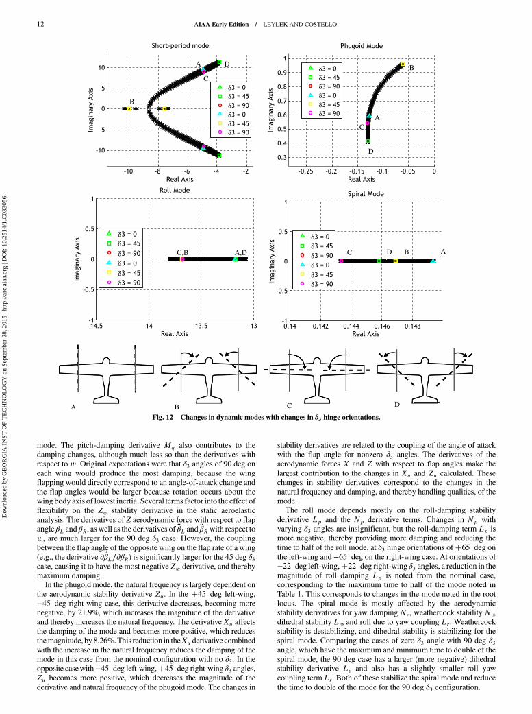
mode. The pitch-damping derivative Mq also contributes to thedamping changes, although much less so than the derivatives withrespect to w. Original expectations were that δ3 angles of 90 deg oneach wing would produce the most damping, because the wingflapping would directly correspond to an angle-of-attack change andthe flap angles would be larger because rotation occurs about thewing body axis of lowest inertia. Several terms factor into the effect offlexibility on the Zw stability derivative in the static aeroelasticanalysis. The derivatives of Z aerodynamic force with respect to flapangle βL and βR, as well as the derivatives of �βL and �βRwith respect tow, are much larger for the 90 deg δ3 case. However, the couplingbetween the flap angle of the opposite wing on the flap rate of a wing(e.g., the derivative ∂�βL∕∂βR) is significantly larger for the 45 deg δ3case, causing it to have the most negative Zw derivative, and therebymaximum damping.In the phugoid mode, the natural frequency is largely dependent on
the aerodynamic stability derivative Zu. In the �45 deg left-wing,−45 deg right-wing case, this derivative decreases, becoming morenegative, by 21.9%, which increases the magnitude of the derivativeand thereby increases the natural frequency. The derivative Xu affectsthe damping of the mode and becomes more positive, which reducesthemagnitude, by 8.26%.This reduction in theXu derivative combinedwith the increase in the natural frequency reduces the damping of themode in this case from the nominal configuration with no δ3. In theopposite casewith−45 deg left-wing,�45 deg right-wing δ3 angles,Zu becomes more positive, which decreases the magnitude of thederivative and natural frequency of the phugoid mode. The changes in
stability derivatives are related to the coupling of the angle of attackwith the flap angle for nonzero δ3 angles. The derivatives of theaerodynamic forces X and Z with respect to flap angles make thelargest contribution to the changes in Xu and Zu calculated. Thesechanges in stability derivatives correspond to the changes in thenatural frequency and damping, and thereby handling qualities, of themode.The roll mode depends mostly on the roll-damping stability
derivative Lp and the Np derivative terms. Changes in Np withvarying δ3 angles are insignificant, but the roll-damping term Lp ismore negative, thereby providing more damping and reducing thetime to half of the roll mode, at δ3 hinge orientations of�65 deg onthe left-wing and −65 deg on the right-wing case. At orientations of−22 deg left-wing,�22 deg right-wing δ3 angles, a reduction in themagnitude of roll damping Lp is noted from the nominal case,corresponding to the maximum time to half of the mode noted inTable 1. This corresponds to changes in the mode noted in the rootlocus. The spiral mode is mostly affected by the aerodynamicstability derivatives for yaw damping Nr, weathercock stability Nv,dihedral stability Lv, and roll due to yaw coupling Lr. Weathercockstability is destabilizing, and dihedral stability is stabilizing for thespiral mode. Comparing the cases of zero δ3 angle with 90 deg δ3angle, which have the maximum and minimum time to double of thespiral mode, the 90 deg case has a larger (more negative) dihedralstability derivative Lv and also has a slightly smaller roll–yawcoupling term Lr. Both of these stabilize the spiral mode and reducethe time to double of the mode for the 90 deg δ3 configuration.
Fig. 12 Changes in dynamic modes with changes in δ3 hinge orientations.
12 AIAA Early Edition / LEYLEK AND COSTELLO
Dow
nloa
ded
by G
EO
RG
IA I
NST
OF
TE
CH
NO
LO
GY
on
Sept
embe
r 28
, 201
5 | h
ttp://
arc.
aiaa
.org
| D
OI:
10.
2514
/1.C
0330
56

The flight dynamic modes of aircraft configurations with nonzeroδ3 angles exhibit an increased sensitivity to other hinge designparameters, such as spring stiffness and damping. This couplingbetween the parameters significantly extends the range of achievablemode tailoring. For example, in Fig. 13a, the spring stiffness is variedfrom 6 to 75 N · m∕rad in increments of 1 N · m∕rad with the δ3angle set at the nominal configuration of 0 deg. Minor movement inthe short-period mode due to variations in the spring stiffness isobserved. In comparison, Fig. 13b shows the effect of the samevariation in spring stiffness on an aircraft with the hinge δ3 angleoriented at�45 deg on the left wing and−45 deg on the right wing.The higher spring-stiffness values approach a rigid aircraftconfiguration, so the modal values match between Figs. 13a and13b in those cases. However, as the hinge becomes more flexible,significantly more movement is apparent in the modes of the 45 degδ3 hinge case, Fig. 13b. The phugoid mode crosses the imaginaryaxis and is unstable for spring-stiffness values less than 9 N · m∕rad.The short-period mode increases damping until it becomes anoverdamped, realmode at a spring stiffness of 10 N · m∕rad, but thenbreaks out into an oscillatory mode at a much higher naturalfrequency as the stiffness is further reduced. The roll mode alsoexperiences a notable change in time to half, unlike the nominal case.With a nonzero δ3 angle, the angle of attack changes as thewing flaps.This introduces coupling between the lateral and longitudinalmotions, which greatly impacts the flight dynamic modes as moreflexibility is introduced.
6. Effect of δ2 Hinge Orientation
The δ2 hinge orientation, depicted in Fig. 5c, is varied from−90 to�90 deg by increments of 1 deg. The δ2 hinge orientation produces
sweep–flap coupling. The left-wing and right-wing δ2 angles arealways equal for symmetry. With a �δ2 orientation, a flap up,increasing the dihedral, will also sweep the wings back. For a −δ2orientation, a flap up will sweep the wings forward. As reported inTable 1 and Fig. 14, this can significantly change the longitudinalmodes of the vehicle, as well as affect the damping of the Dutch-rollmode. The phugoid mode and the short-period mode show oppositetrends in terms. In the short period, the lowest damping occurs at�45 deg δ2 angles, and the highest occurs at −45 deg δ2 angles. Inthe Dutch-roll mode, the highest mode damping occurs at 90 deghinge angles, whereas the lowest damping is without any δ2 anglepresent.The damping ratio of the Dutch-roll mode changes 1.6%.
However, the δ2 hinge orientation causes large variations in theresponse of the longitudinal modes. The natural frequency of theshort-period mode changes 28.7%, corresponding to a 65.7%increase in theCAP.Themaximumchange in the damping ratio of theshort-period mode due to the δ2 hinge orientation is 88%. This, too,provides ameans to improve the Level rating of the flying qualities ofthe aircraft. The phugoid mode experiences possible increases in thenatural frequency of 50.2% and in the damping ratio of 71.5%.Employing static aeroelastic analysis, changes in the short-period-
mode natural frequency are largely due to changes in the stabilityderivative Mw. Interestingly, the derivative Zw does not changesignificantly. The changes in Mw and short-period mode are likelydue to themovement in the aerodynamic center of thewing relative tothe c.g. of the vehicle as thewing sweeps forward or aft with flapping.The pitch-damping derivative Mq, which also contributes to thedamping of the short-period mode, changes slightly by 2.4% fromthe nominal case of zero δ2 angle to−45 deg δ2 angles to increase the
Fig. 13 Root loci for varying spring stiffness for a) δ3 of 0 deg, and b) δ3 of �45 deg on left wing, −45 deg on right wing.
AIAA Early Edition / LEYLEK AND COSTELLO 13
Dow
nloa
ded
by G
EO
RG
IA I
NST
OF
TE
CH
NO
LO
GY
on
Sept
embe
r 28
, 201
5 | h
ttp://
arc.
aiaa
.org
| D
OI:
10.
2514
/1.C
0330
56

damping. In the phugoid, the derivative Zu does not changesignificantly with varying δ2 angle. The derivativeXu, which appearsin the damping of the phugoid, changes slightly by 2.7% from thenominal case of zero δ2 angle to−45 deg δ2 angles, reducing themodedamping. These small changes do not explain the large changes in thephugoid mode observed from the root locus with varying δ2 hingeorientations, suggesting that the flapping velocity and accelerationterms, which are not accounted for in the static aeroelastic analysis, areimportant to the phugoid-mode characteristics.
IV. Conclusions
The emergence of cost-effective multimaterial manufacturingmethods allows complex structures to be fabricated that incorporateflexible structures,which act asdiscrete elastic hinges intoan otherwiserigid structure. This presents new possibilities for designing aircraft,particularly small unmanned aircraft. Rather than using typical designparameters, such as the geometry and arrangement of the aircraftcomponents, the lifting surfaces can be constructed with a chordwisestrip of relatively soft structural material, which functions as an elasticdiscrete hinge.The characteristics of the hinge can thenbe used to tailorthe dynamics of the vehicle.From a series of parametric trade studies, it is shown that an
elastic hinge embedded in the wing causes coupling between theflexible modes and traditional low-order dynamic modes, changingthe flight dynamic response of the vehicle. Along with the stiffnessof the joint material, the orientation of the hinge introduces couplingof the lateral and longitudinal motions of the wing to affect theresponse. Together, these provide a range of short-period-modecharacteristics from Level 4 to Level 1 flying-qualities ratings, suchthat the elasticity and hinge orientation can be used to tailor the short-period handling qualities. Nonzero hinge orientations also showa significant increase in sensitivity to variations in the stiffnessand damping of the hinge, which allows even further tailoring ofthe modes. Static aeroelastic analysis highlights the changes inaerodynamic stability derivatives that drive the changes in the modeswith variations in the hinge parameters, and identifies cases in whichthe modal changes are largely affected by the transient dynamics, forwhich a static analysis is insufficient to explain the results. Whileprevious work generally focused on highly flexible wings, whichdegraded flying qualities, this paper presents a full sweep through awide range of stiffness values and shows how decreasing the stiffnesscan improve handling qualities, particularly in the longitudinalmodes. It is also shown how the introduction of a discrete structuralhinge can increase the range of short-period response characteristicsproduced by configuration changes of the vehicle alone. The lateral
modes of the vehicle are not significantly impacted by the presence ofthe compliant hinge. The reasons for this could stem from thedihedral being kept fixed at a certain value. The lateral modes alsodepend on the aerodynamics of the vertical tail, for which addition ofcompliancy was not examined in this paper.
Acknowledgment
This material is based upon the work supported by the NationalScience Foundation Graduate Research Fellowship Program undergrant number DGE-1148903.
References
[1] Dimitrov, D., Schreve, K., and de Beer, N., “Advances in ThreeDimensional Printing—State of the Art and Future Perspectives,” RapidPrototyping Journal, Vol. 12, No. 3, 2006, pp. 136–147.doi:10.1108/13552540610670717
[2] Gouker, R., Gupta, S., Bruck, H., and Holzschuh, T., “Manufacturing ofMulti-Material Compliant Mechanisms Using Multi-Material Mold-ing,” International Journal of Advanced Manufacturing Technology,Vol. 30, Nos. 11–12, 2006, pp. 1049–1075.doi:10.1007/s00170-005-0152-4
[3] Choi, J., Kim, H., and Wicker, R., “Multi-Material Stereolithography,”Journal of Materials Processing Technology, Vol. 211, No. 3, 2011,pp. 318–328.doi:10.1016/j.jmatprotec.2010.10.003
[4] Cutkosky, M. R., and Kim, S., “Design and Fabrication of Multi-Material Structures for Bioinspired Robots,” Philosophical Trans-
actions of the Royal Society of London, Series A: Mathematical,
Physical and Engineering Sciences, Vol. 367, No. 1894, 2009,pp. 1799–1813.doi:10.1098/rsta.2009.0013
[5] Bejgerowski, W., Gerdes, J. W., Gupta, S. K., and Bruck, H. A.,“Design and Fabrication of Miniature Compliant Hinges for Multi-Material Compliant Mechanisms,” International Journal of AdvancedManufacturing Technology, Vol. 57, Nos. 5–8, 2011, pp. 437–452.
[6] Pankonien, A., and Inman, D. J., “Experimental Testing of SpanwiseMorphing Trailing Edge Concept,” SPIE Conference on Smart
Structures and Materials: Active and Passive Smart Structures and
Integrated Systems, Vol. 8688, Soc. of Photo-Optical InstrumentationEngineers, Bellingham, WA, 2013, pp. 1–13.doi:10.1117/12.2009400
[7] Webb,A., andCostello,M., “WingArticulation ofMicroAirVehicles toReduce Gust Sensitivity,” AIAA Atmospheric Flight Mechanics
Conference, AIAA Paper 2008-6712, Aug. 2008.[8] Oduyela, A., and Slegers, N., “Gust Mitigation of Micro Air Vehicles
Using Passive ArticulatedWings,” Scientific World Journal, Vol. 2014,2014, pp. 1–10.doi:10.1155/2014/598523
Fig. 14 Changes in dynamic modes with changes in δ2 hinge orientations.
14 AIAA Early Edition / LEYLEK AND COSTELLO
Dow
nloa
ded
by G
EO
RG
IA I
NST
OF
TE
CH
NO
LO
GY
on
Sept
embe
r 28
, 201
5 | h
ttp://
arc.
aiaa
.org
| D
OI:
10.
2514
/1.C
0330
56

[9] Porter, R. F., and Brown, J. H., Jr., “Evaluation of the Gust-AlleviationCharacteristics and HandlingQualities of a Free-WingAircraft,”NASACR-1523, April 1970.
[10] Tanaka, H., Whitney, J. P., and Wood, R. J., “Effect of Flexural andTorsional Wing Flexibility on Lift Generation in Hoverfly Flight,”Integrative and Comparative Biology, Vol. 51, No. 1, 2011,pp. 142–150.doi:10.1093/icb/icr051
[11] Krus, P., “NaturalMethods for Flight Stability in Birds,”World Aviation
Congress, AIAA Paper 1997-5653, 1997, pp. 1–6.[12] Leishman, J. G., Principles of Helicopter Aerodynamics, 2nd ed.,
Cambridge Univ. Press, New York, 2006, pp. 198–199.[13] Waterman, W. D., Santa Monica Canyon, CA, U.S. Patent Application
for “Aeroplane Control,” Serial No. 312,242, filed 13 Oct. 1928,Dec. 1930.
[14] Shirk,M. H., Hertz, T. J., andWeisshaar, T. A., “Aeroelastic Tailoring—Theory, Practice, and Promise,” Journal of Aircraft, Vol. 23, No. 1,1986, pp. 6–18.doi:10.2514/3.45260
[15] Weisshaar, T. A., Nam, C., and Batista-Rodriguez, A., “AeroelasticTailoring for Improved UAV Performance,” 39th AIAA/ASME/ASCE/
AHS/ASC Structures, Structural Dynamics, and Materials Conference
and Exhibit, AIAA, Reston, VA, 1998, pp. 1–13.[16] Pitt, D., “Static and Dynamic Aeroelastic Analysis of Structural Wing
Fold Hinges That Are Employed as an Aeroelastic Tailoring Tool,” 45thAIAA/ASME/ASCE/AHS/ASC Structures, Structural Dynamics, and
Materials Conference, AIAA, Reston, VA, April 2004, pp. 1–11.[17] Ameri, N., Lowenberg, M. H., and Friswell, M. I., “Modelling the
Dynamic Response of a Morphing Wing with Active Winglets,” AIAAAtmospheric Flight Mechanics Conference, AIAA Paper 2007-6500,Aug. 2007.
[18] Abdulrahim, M., and Lind, R., “Flight Testing and ResponseCharacteristics of a Variable Gull-Wing Morphing Aircraft,” AIAA
Guidance, Navigation, and Control Conference, AIAA Paper 2004-5113, Aug. 2004.
[19] Abdulrahim,M., and Lind, R., “Control and Simulation of aMulti-RoleMorphing Micro Air Vehicle,” AIAA Guidance, Navigation, and
Control Conference, AIAA Paper 2005-6481, Aug. 2005.[20] Abdulrahim, M., and Lind, R., “Using Avian Morphology to Enhance
Aircraft Maneuverability,” AIAA Atmospheric Flight Mechanics
Conference, AIAA Paper 2006-6643, Aug. 2006.[21] Agenbag, D. S., Theron, N. J., and Huyssen, R. J., “Pitch Handling
Qualities Investigation of the Tailless Gull-Wing Configuration,”Journal of Aircraft, Vol. 46, No. 2, 2009, pp. 683–691.doi:10.2514/1.39755
[22] Paranjape, A. A., Chung, S.-J., and Selig, M. S., “Flight Mechanics of aTailless Articulated Wing Aircraft,” Bioinspiration & Biomimetics,Vol. 6, No. 2, 2011, Paper 026005.doi:10.1088/1748-3182/6/2/026005
[23] Paranjape, A. A., Chung, S.-J., Hilton, H. H., and Chakravarthy, A.,“Dynamics and Performance of Tailless Micro Aerial Vehicle withFlexible Articulated Wings,” AIAA Journal, Vol. 50, No. 5, 2012,pp. 1177–1188.doi:10.2514/1.J051447
[24] Babcock, J., and Lind, R., “Aeroelastic Effects of Wing Stiffness on theFlight Dynamics of a MAV,” AIAA Atmospheric Flight Mechanics
Conference, AIAA, Reston, VA, Aug. 2012, pp. 1–19.[25] Waszak, M. R., and Schmidt, D. K., “Flight Dynamics of Aeroelastic
Vehicles,” Journal of Aircraft, Vol. 25, No. 6, June 1988, pp. 563–571.doi:10.2514/3.45623
[26] Weisshaar, T. A., and Zeiler, T. A., “Dynamic Stability of FlexibleForward Swept Wing Aircraft,” AIAA Atmospheric Flight Mechanics
Conference, AIAA, New York, Aug. 1982, pp. 1–11.[27] Cerra, J. J., II, Calico, R. A., and Noll, T. E., “Modelling of Rigid-Body
and Elastic Aircraft Dynamics for Flight Control Development,” AIAAAstrodynamics Conference, AIAA, New York, 1986, pp. 386–395.
[28] Siepenkotter, N., and Alles, W., “Stability Analysis of the NonlinearDynamics of Flexible Aircraft,” Aerospace Science and Technology,Vol. 9, No. 2, 2005, pp. 135–141.doi:10.1016/j.ast.2004.10.005
[29] Tuzcu, I., “On the Stability of Flexible Aircraft,”Aerospace Science andTechnology, Vol. 12, No. 5, 2008, pp. 376–384.doi:10.1016/j.ast.2007.09.003
[30] Silvestre, F. J., and Paglione, P., “Dynamics and Control of a FlexibleAircraft,” AIAA Atmospheric Flight Mechanics Conference, AIAA,Reston, VA, Aug. 2008, pp. 1–18.
[31] Baghdadi, N., Lowenberg, M. H., and Isikveren, A. T., “Analysis ofFlexible Aircraft Dynamics Using Bifurcation Methods,” Journal of
Guidance, Control, and Dynamics, Vol. 34, No. 3, 2011, pp. 795–809.doi:10.2514/1.51468
[32] Andrews, S. P., “Modelling and Simulation of Flexible Aircraft: HandlingQualities with Active Load Control,” Ph.D. Dissertation, School ofEngineering, Cranfield Univ., Cranfield, England, U.K., 2011.
[33] Newman, B., “Proposed Flying Quality Metrics and Simulation Studiesfor Elastic Vehicles,” AIAA Atmospheric Flight Mechanics Conference,AIAA Paper 1996-3423, July 1996, pp. 500–509.
[34] Schmidt, D.K., andRaney,D. L., “Modeling and Simulation of FlexibleFlight Vehicles,” Journal of Guidance, Control, andDynamics, Vol. 24,No. 3, May 2001, pp. 539–546.doi:10.2514/2.4744
[35] Phillips, W. F., and Snyder, D. O., “Modern Adaptation of Prandtl’sClassic Lifting-Line Theory,” Journal of Aircraft, Vol. 37, No. 4, 2000,pp. 662–670.doi:10.2514/2.2649
[36] Anderson, J. D. Jr., Corda, S., and Van Wie, D. M., “Numerical LiftingLine Theory Applied to Drooped Leading-Edge Wings Below andAbove Stall,” Journal of Aircraft, Vol. 17, No. 12, 1980, pp. 898–904.doi:10.2514/3.44690
[37] Selig, M. S., “Modeling Full-Envelope Aerodynamics of Small UAVs inRealtime,”AIAAAtmosphericFlightMechanicsConference, AIAAPaper2010-7635, Aug. 2010.
[38] Ogata, K.,Modern Control Engineering, 4th ed., Prentice–Hall, UpperSaddle River, NJ, 2002, pp. 112–114.
[39] Anon., “Flying Qualities of Piloted Airplanes,” MIL-SPEC, MIL-F-8785C, 1980.
[40] Bisplinghoff, R. L., Ashley, H., and Halfman, R. L., Aeroelasticity,Dover, Mineola, NY, 1983, pp. 421–427.
AIAA Early Edition / LEYLEK AND COSTELLO 15
Dow
nloa
ded
by G
EO
RG
IA I
NST
OF
TE
CH
NO
LO
GY
on
Sept
embe
r 28
, 201
5 | h
ttp://
arc.
aiaa
.org
| D
OI:
10.
2514
/1.C
0330
56