use of cpt in geotechnical earthquake engineering of cpt in geotechnical earthquake engineering ......
TRANSCRIPT
Use of CPT in Geotechnical Earthquake Engineering
Prof. Scott M. Olson, PhD, PE
Use of Cone Penetration Test for Foundation Analysis and Design2006 Annual Meeting
Transportation Research Board
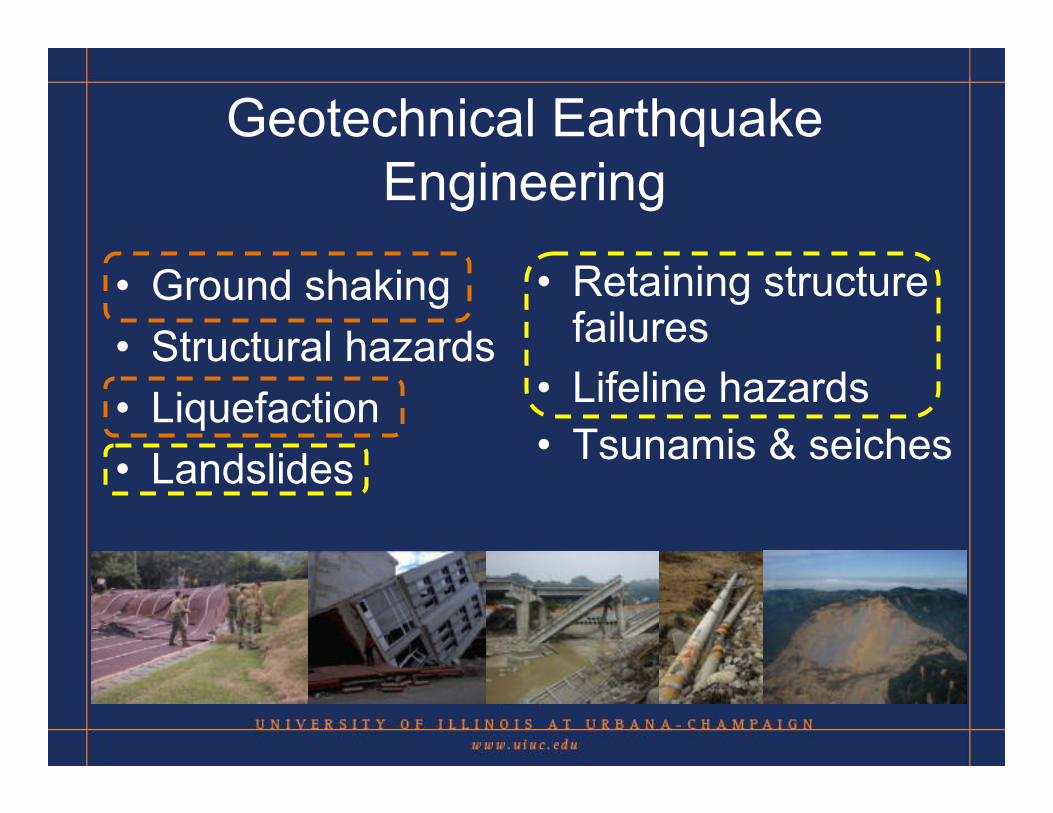
Geotechnical Earthquake Engineering
• Ground shaking• Structural hazards• Liquefaction• Landslides
• Retaining structure failures
• Lifeline hazards• Tsunamis & seiches
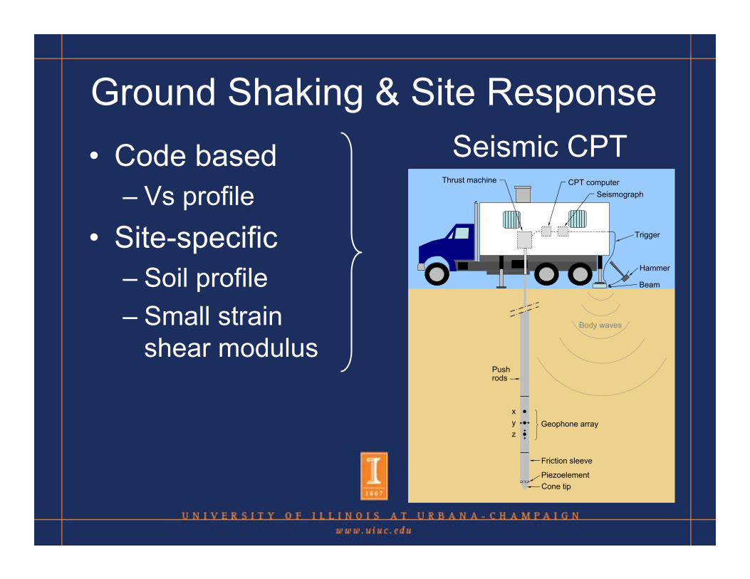
Ground Shaking & Site Response • Code based
– Vs profile• Site-specific
– Soil profile– Small strain
shear modulus
Seismic CPT
xyz
Geophone array
Friction sleeve
PiezoelementCone tip
Pushrods
Body waves
Beam
Hammer
Trigger
SeismographCPT computerThrust machine
xyz
Geophone array
Friction sleeve
PiezoelementCone tip
Pushrods
Body waves
Beam
Hammer
Trigger
SeismographCPT computerThrust machine
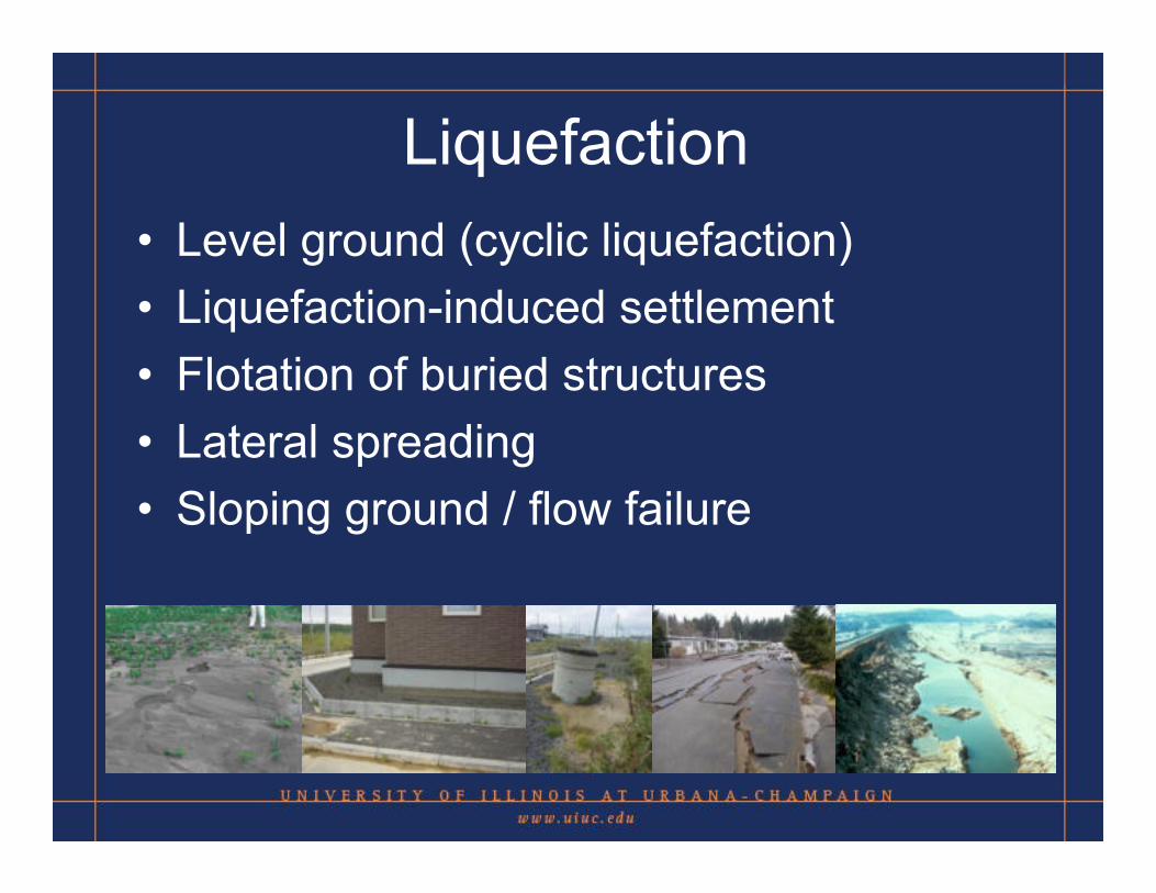
Liquefaction • Level ground (cyclic liquefaction)• Liquefaction-induced settlement• Flotation of buried structures• Lateral spreading• Sloping ground / flow failure

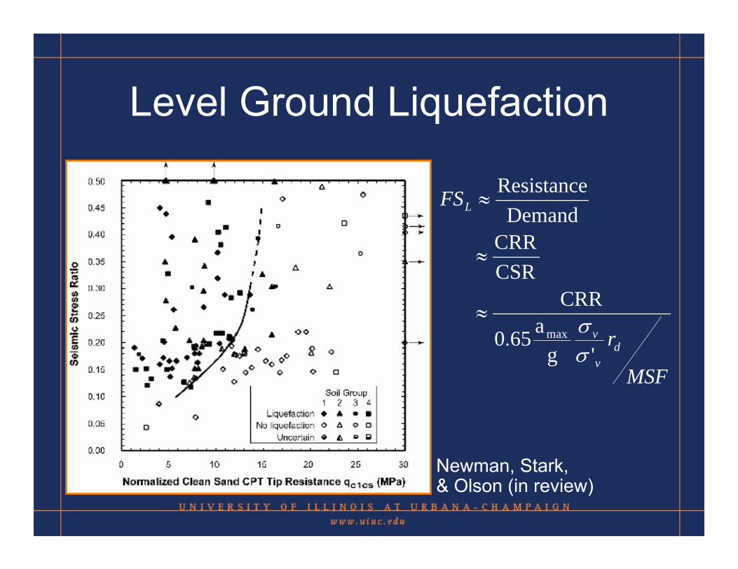
Level Ground Liquefaction
1,1 cFCcsc qCq ⋅=Clean sandbase curve
Newman, Stark, & Olson(in review)
Level Ground Liquefaction
Newman, Stark, & Olson (in review)
MSF
r
FS
dv
v
L
'ga0.65
CRR
CSRCRR
DemandResistance
max
σσ≈
≈
≈
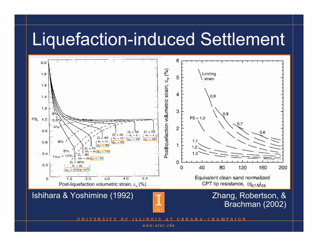
Liquefaction-induced Settlement
Ishihara & Yoshimine (1992) Zhang, Robertson, &Brachman (2002)
Post-liquefaction volumetric strain, εv (%)
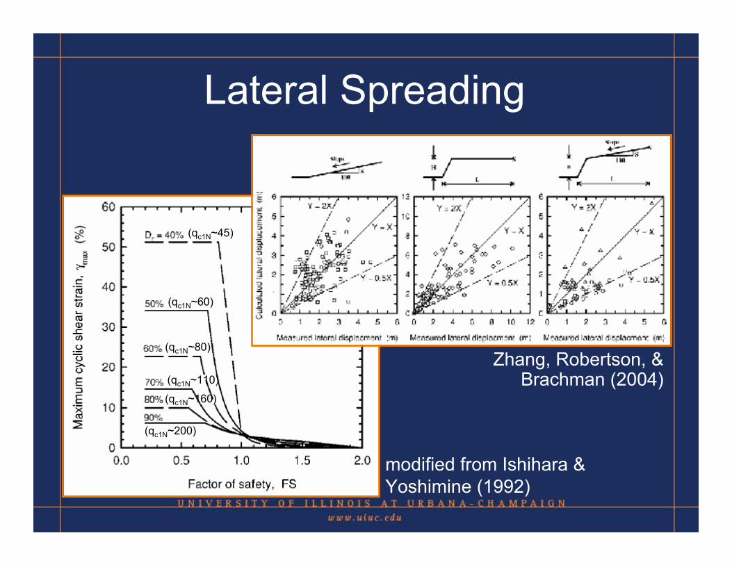
Lateral Spreading
(qc1N~45)
(qc1N~60)
(qc1N~80)
(qc1N~110)
(qc1N~160)
(qc1N~200)
modified from Ishihara & Yoshimine (1992)
Zhang, Robertson, &Brachman (2004)

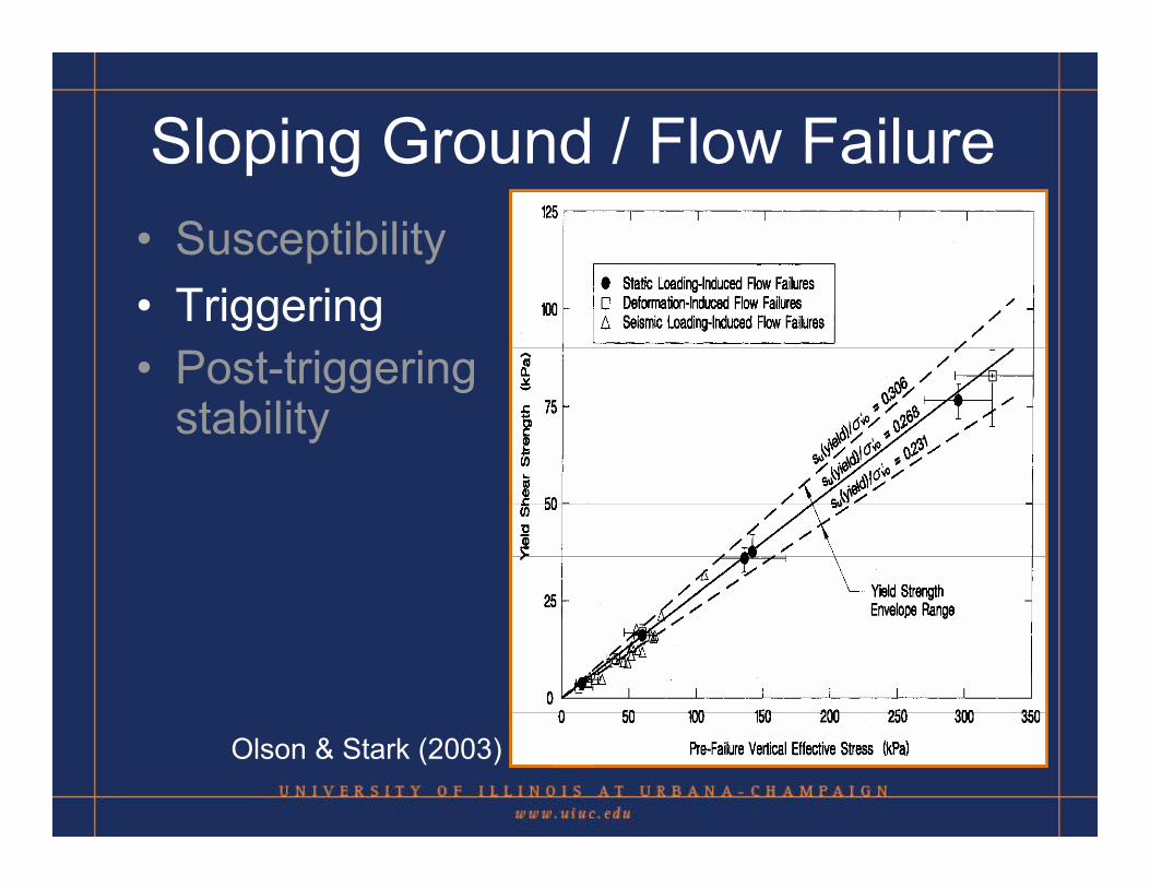
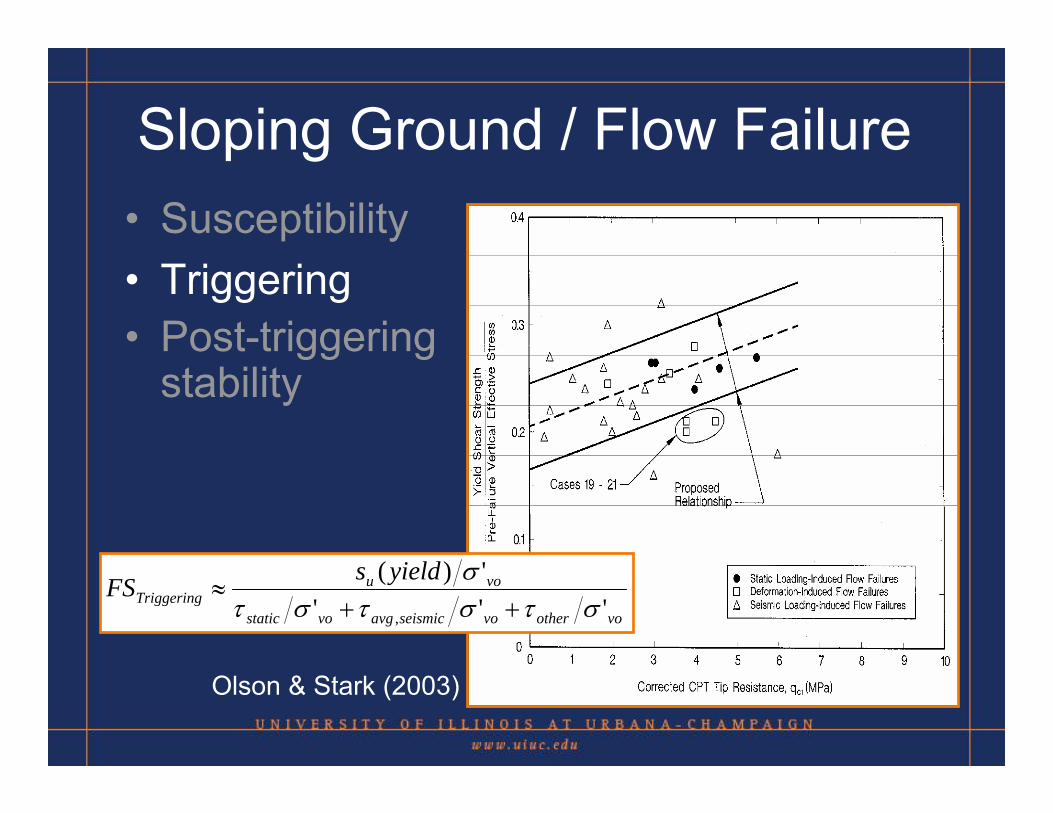
Sloping Ground / Flow Failure• Susceptibility• Triggering• Post-triggering
stability
Olson & Stark (2003)
CONTRACTIVE DILATIVE
Sloping Ground / Flow Failure• Susceptibility• Triggering• Post-triggering
stability
Olson & Stark (2003)
Sloping Ground / Flow Failure• Susceptibility• Triggering• Post-triggering
stability
Olson & Stark (2003)
voothervoseismicavgvostatic
vouTriggering
yieldsFS'''
')(
, στστστσ
++≈
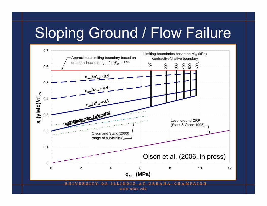
Sloping Ground / Flow Failure
• Susceptibility• Triggering• Post-triggering
stability
0
0.1
0.2
0.3
0.4
0.5
0.6
0.7
0 2 4 6 8 10 12
qc1
τ / σ
' vo
100
200
300
400
500
600
Limiting boundaries based on σ'vo (kPa)contractive/dilative boundary
Olson and Stark (2003)range of su(yield)/σ'vo
Level ground CRR(Stark & Olson 1995)
Approximate limiting boundary based ondrained shear strength for φ 'ss = 30o
Olson et al. (2006, in press)
qc1 (MPa)
s u(y
ield
)/σ' vo
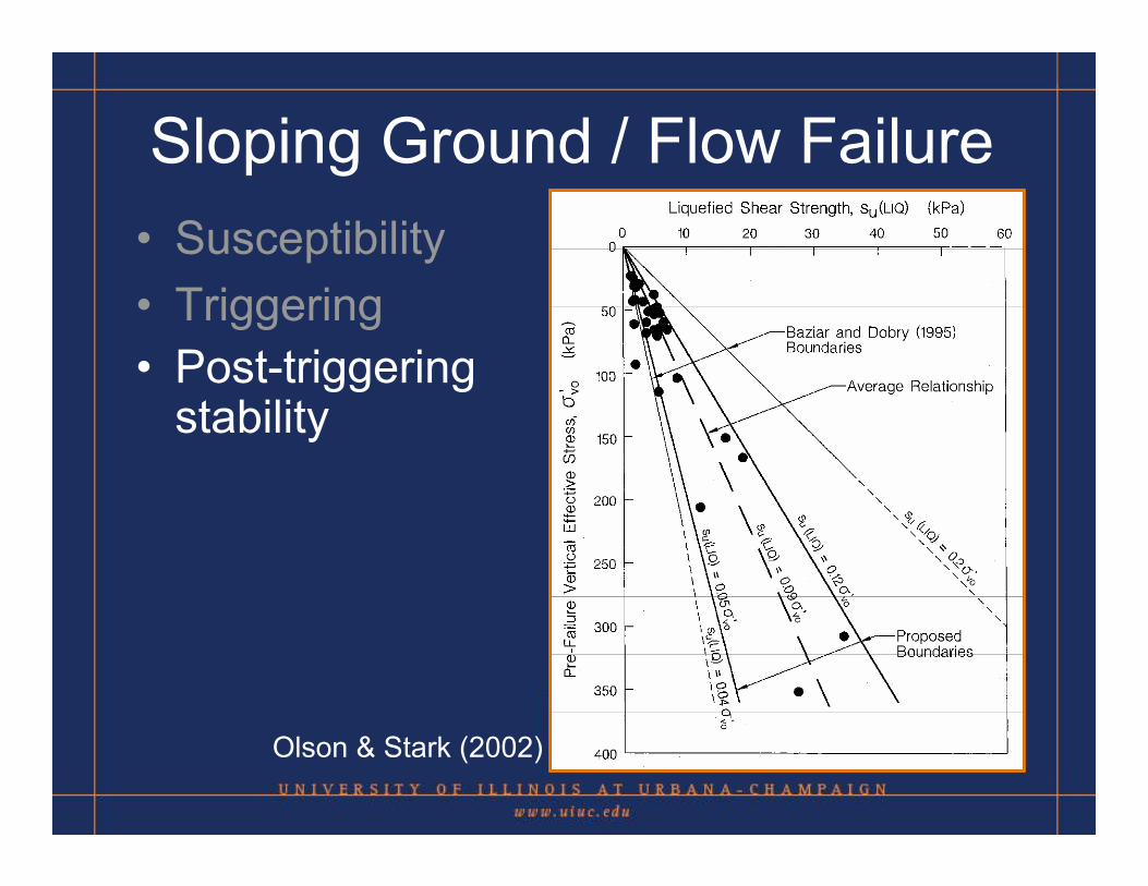
Sloping Ground / Flow Failure• Susceptibility• Triggering• Post-triggering
stability
Olson & Stark (2002)
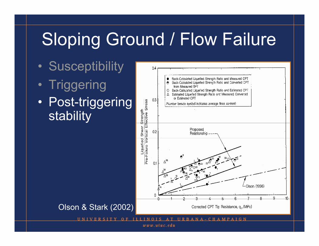
Sloping Ground / Flow Failure• Susceptibility• Triggering• Post-triggering
stability
Olson & Stark (2002)
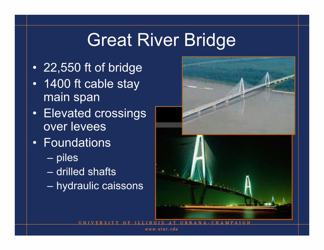
Great River Bridge• 22,550 ft of bridge• 1400 ft cable stay
main span• Elevated crossings
over levees• Foundations
– piles– drilled shafts– hydraulic caissons
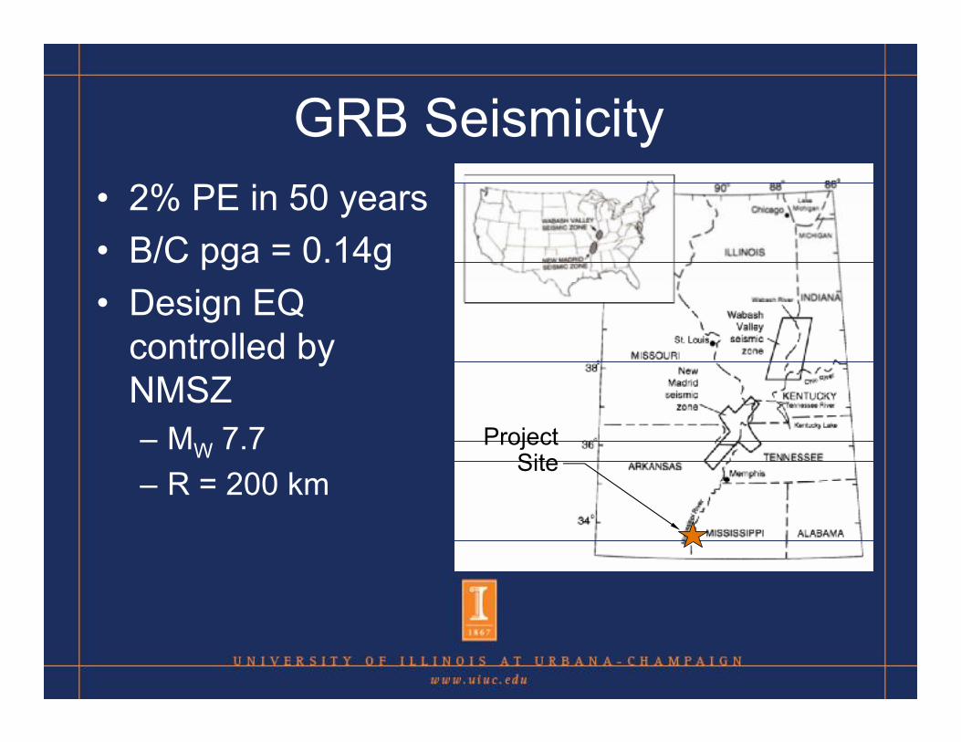
GRB Seismicity• 2% PE in 50 years• B/C pga = 0.14g• Design EQ
controlled by NMSZ– MW 7.7– R = 200 km
ProjectSite
ProjectSite
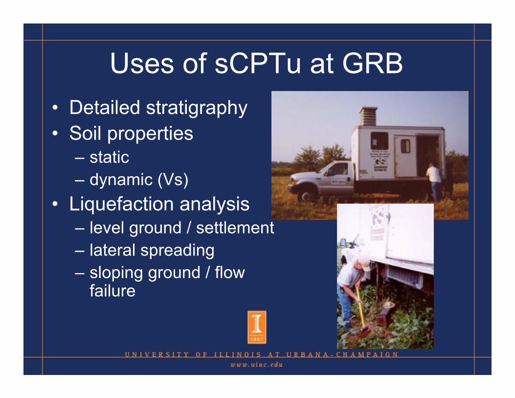
Uses of sCPTu at GRB• Detailed stratigraphy• Soil properties
– static– dynamic (Vs)
• Liquefaction analysis– level ground / settlement– lateral spreading– sloping ground / flow
failure
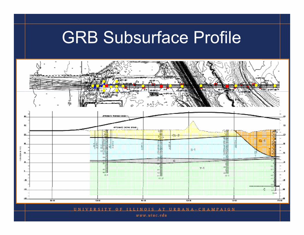
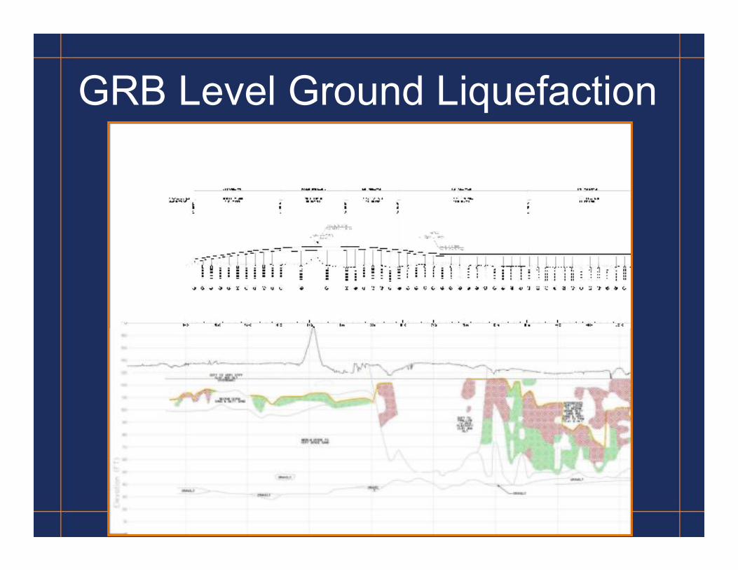
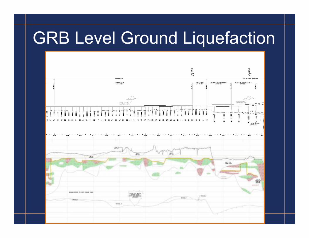
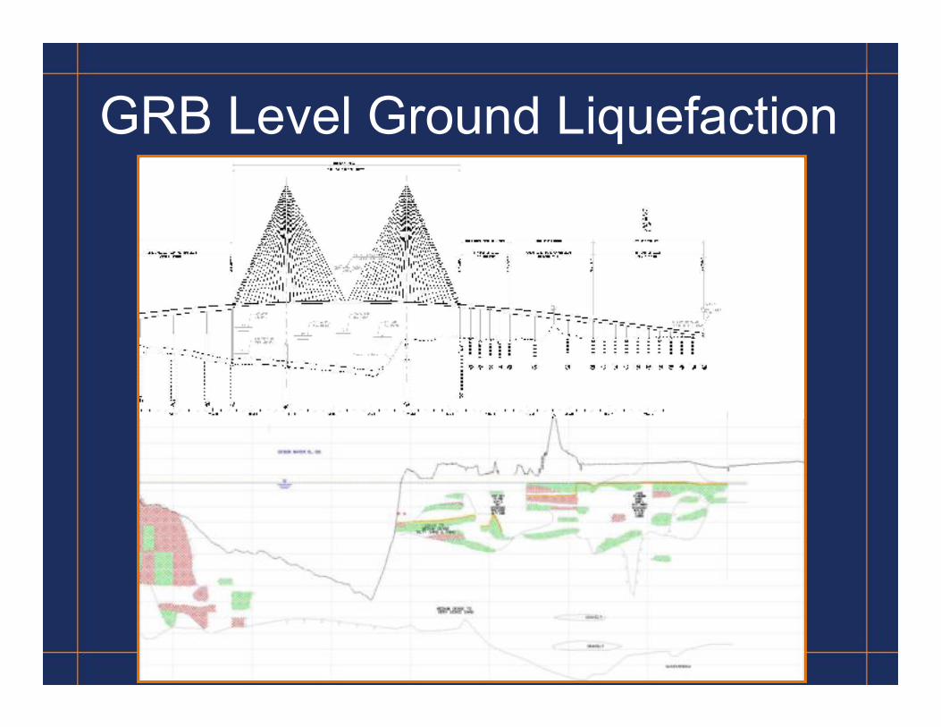
GRB Subsurface Profile

GRB Subsurface Profile
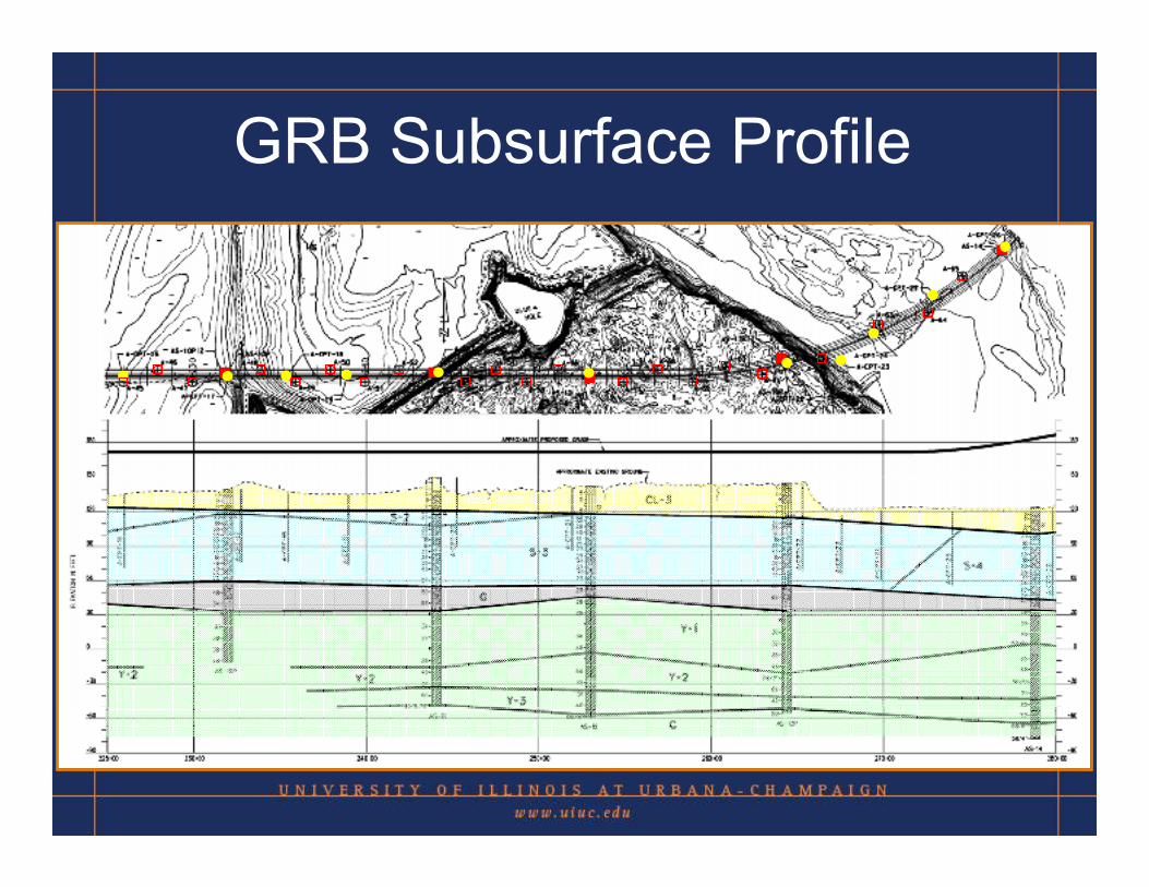
GRB Subsurface Profile
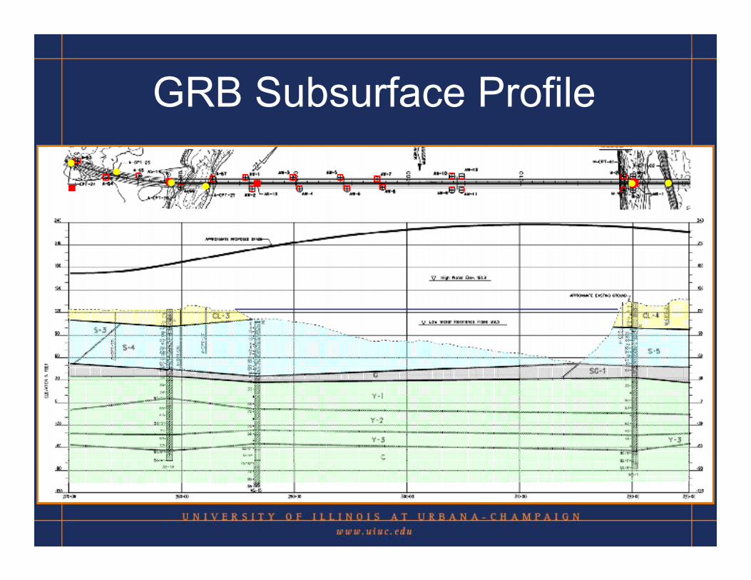
GRB Subsurface Profile
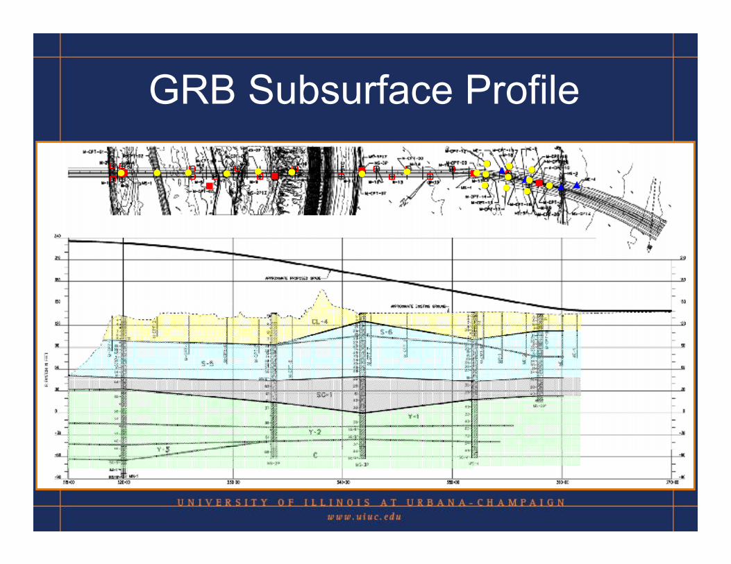
GRB Subsurface Profile
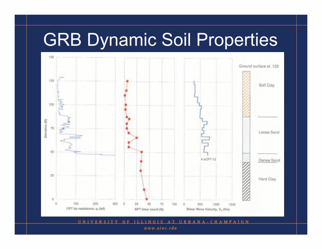
GRB Dynamic Soil Properties
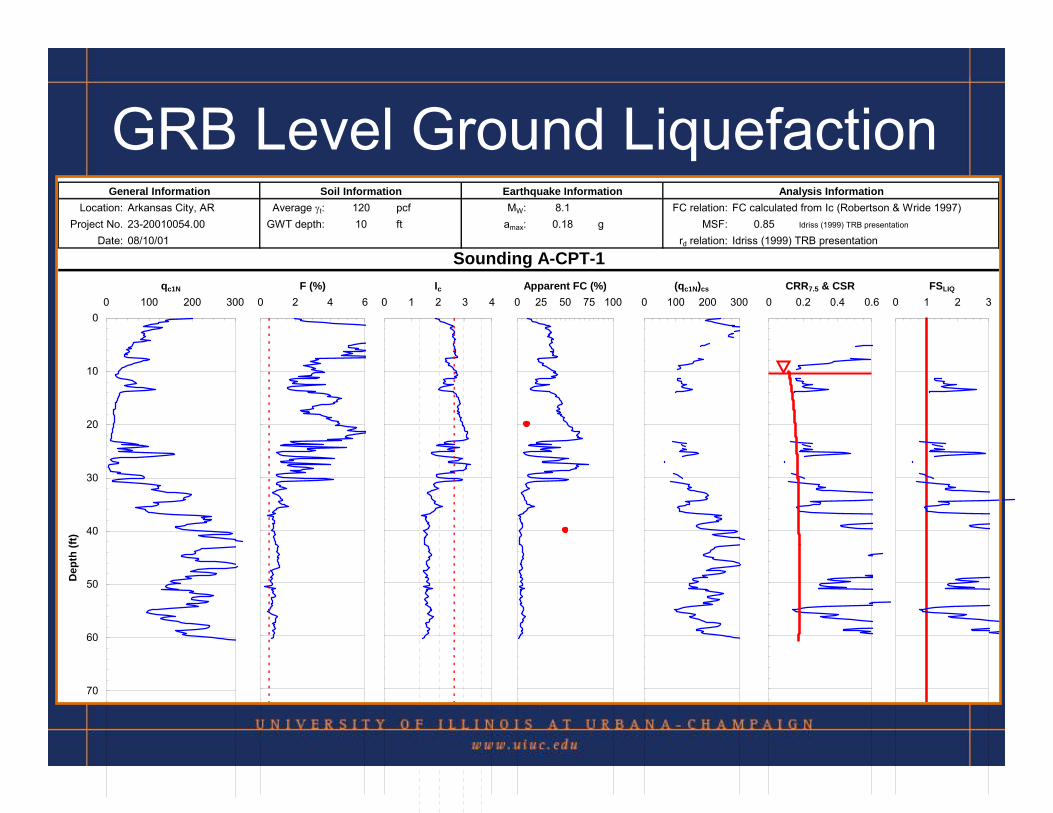
GRB Level Ground LiquefactionGeneral Information Soil Information Earthquake Information Analysis Information
Location: Arkansas City, AR Average γt: 120 pcf MW: 8.1 FC relation: FC calculated from Ic (Robertson & Wride 1997)Project No. 23-20010054.00 GWT depth: 10 ft amax: 0.18 g MSF: 0.85 Idriss (1999) TRB presentation
Date: 08/10/01 rd relation: Idriss (1999) TRB presentation
Sounding A-CPT-1
0
10
20
30
40
50
60
70
0 100 200 300qc1N
Dep
th (f
t)
0 2 4 6F (%)
0 1 2 3 4Ic
0 25 50 75 100Apparent FC (%)
0 100 200 300(qc1N)cs
0 0.2 0.4 0.6CRR7.5 & CSR
0 1 2 3FSLIQ
GRB Level Ground Liquefaction
GRB Level Ground Liquefaction
GRB Level Ground Liquefaction
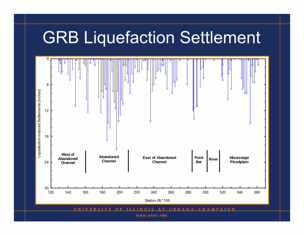
GRB Liquefaction Settlement
120 140 160 180 200 220 240 260 280 300 320 340 360
Station (ft) *100
30
24
18
12
6
0
Liqu
efac
tion-
Indu
ced
Settl
emen
ts (i
nche
s)
West ofAbandoned
ChannelAbandoned
ChannelWest of Abandoned
ChannelPointBar
MississippiFloodplain
RiverEast
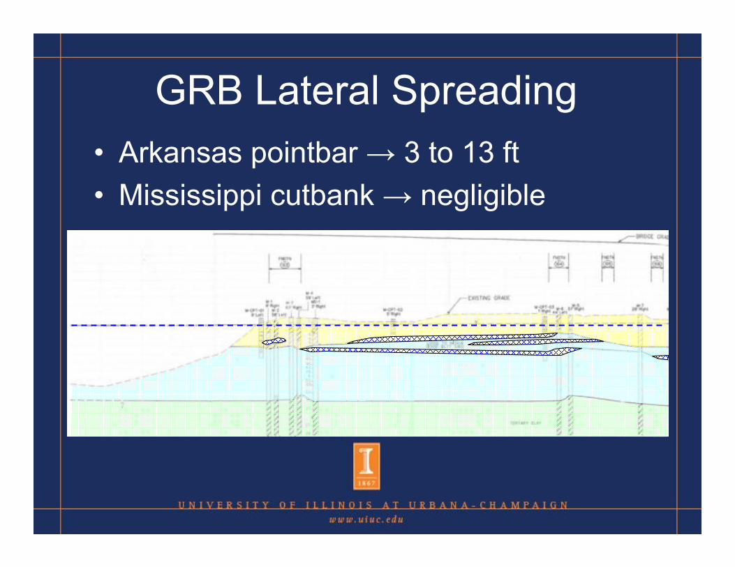
GRB Lateral Spreading• Arkansas pointbar → 3 to 13 ft• Mississippi cutbank → negligible
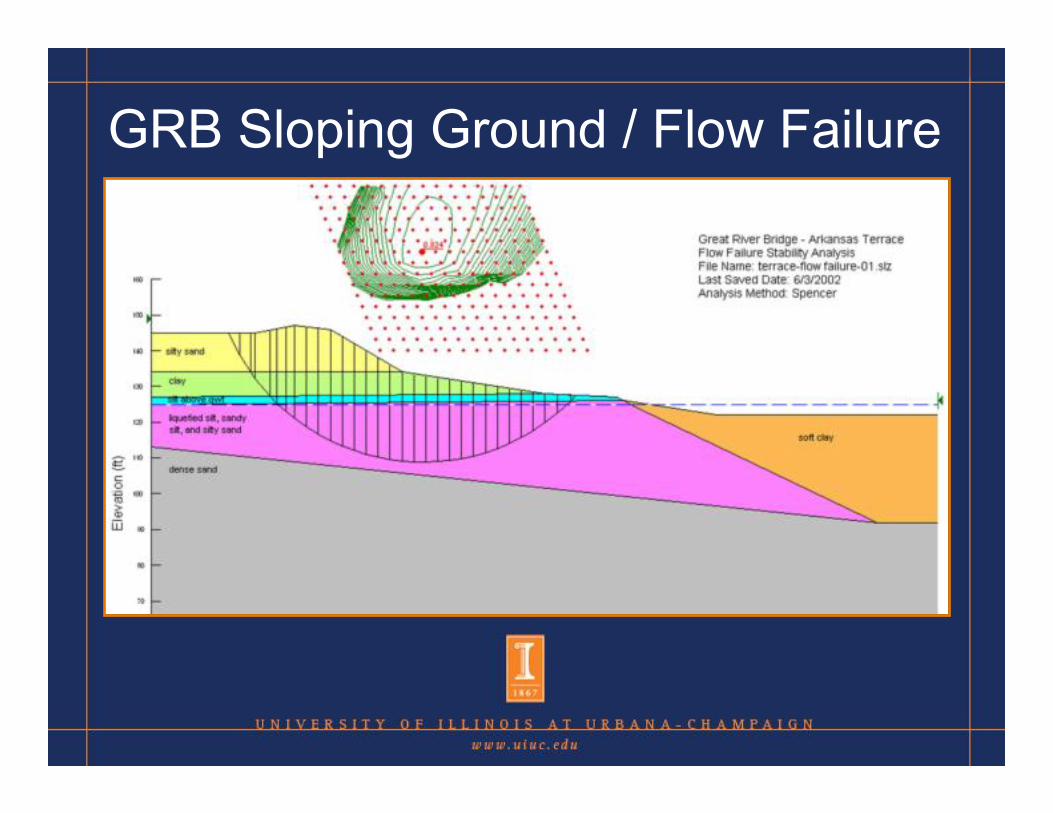
GRB Sloping Ground / Flow Failure

GRB Sloping Ground / Flow Failure

Conclusions • sCPTu is an excellent site investigation
tool when conditions are appropriate – quality & quantity of data – rapid & versatile– cost-effective– repeatable
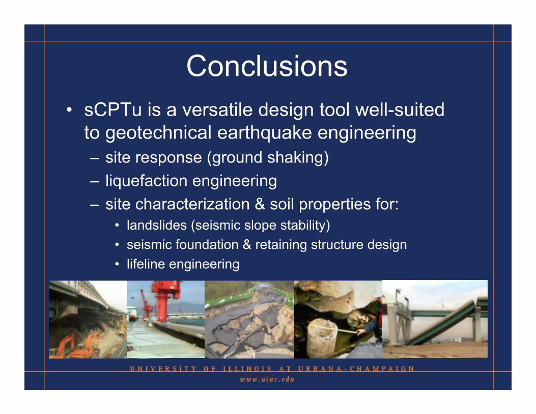
Conclusions • sCPTu is a versatile design tool well-suited
to geotechnical earthquake engineering – site response (ground shaking) – liquefaction engineering– site characterization & soil properties for:
• landslides (seismic slope stability)• seismic foundation & retaining structure design • lifeline engineering
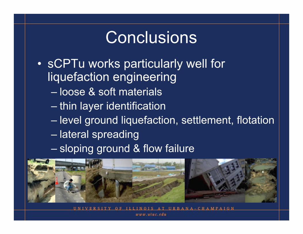
Conclusions • sCPTu works particularly well for
liquefaction engineering– loose & soft materials– thin layer identification– level ground liquefaction, settlement, flotation– lateral spreading– sloping ground & flow failure

Thank You!
Questions???