use of “review” and “back analysis” to implement the “best ... · • contractor’s temp...
TRANSCRIPT
By
Duncan Nicholson, Director Ove Arup and Partners Ltd
OBSERVATIONAL METHODUse of “review” and “back analysis” to
implement the “Best Way Out” approach.
TERRASOLBureau d’Ingénieurs-Conseils en Géotechnique Immeuble Central Seine42-52 Quai de la RapéeCS 71230 75583 Paris CEDEX 12FRANCE
Joint Meeting BGA and CFMS
Friday 2nd December 2011

2
Contents
• Peck’s Observational Method (OM) Principles- “Ab Initio” and “Best way Out”
• Ciria (1999) R185 - OM Definition and Process
• “Predefined Design” and OM “Best Way Out”
• “Best way out” processes- Trigger Values- Review and back analysis
• Basement Case Histories - Kings Place- Nicol Highway- Canary Wharf Crossrail Station
• Conclusions
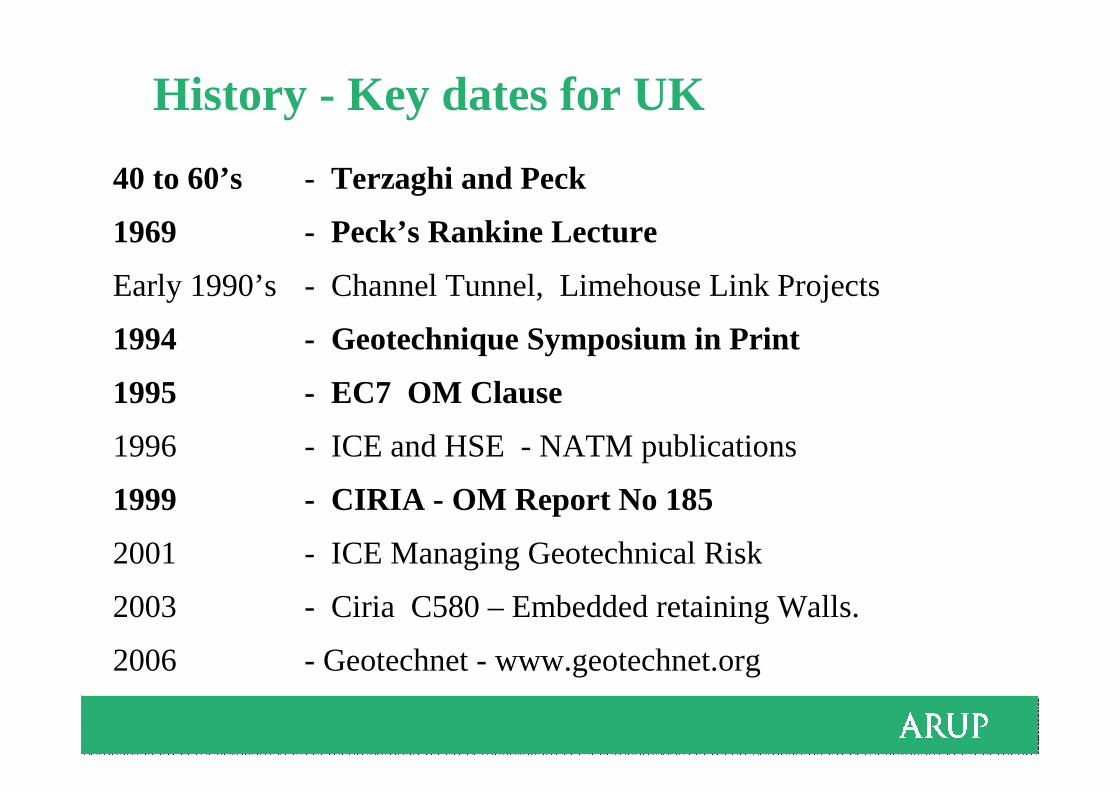
History - Key dates for UK
40 to 60’s - Terzaghi and Peck
1969 - Peck’s Rankine Lecture
Early 1990’s - Channel Tunnel, Limehouse Link Projects
1994 - Geotechnique Symposium in Print
1995 - EC7 OM Clause
1996 - ICE and HSE - NATM publications
1999 - CIRIA - OM Report No 185
2001 - ICE Managing Geotechnical Risk
2003 - Ciria C580 – Embedded retaining Walls.
2006 - Geotechnet - www.geotechnet.org
4
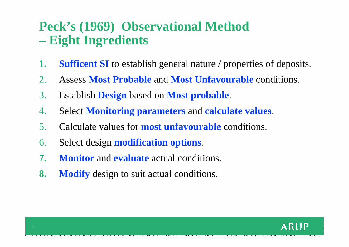
Peck’s (1969) Observational Method – Eight Ingredients
1. Sufficent SI to establish general nature / properties of deposits.
2. AssessMost ProbableandMost Unfavourable conditions.
3. EstablishDesignbased onMost probable.
4. SelectMonitoring parameters andcalculate values.
5. Calculate values formost unfavourableconditions.
6. Select designmodification options.
7. Monitor andevaluateactual conditions.
8. Modify design to suit actual conditions.

5
Peck (1969) OM applications
“Ab Initio” OM - planned from start of work
• Harris Bank – Chicago strut monitoring• Bay Transit Tunnels – Volume loss
“Best way out” OM – introduced during work
• Cleveland Ore Terminal - soft clays – stockpiles of iron ore• Cape Kennedy Causeway – Hydraulic fill
6
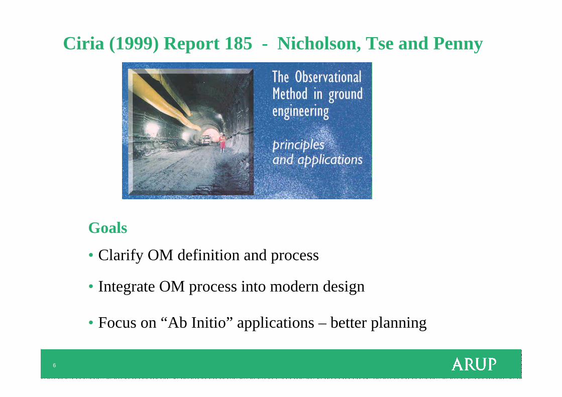
Ciria (1999) Report 185 - Nicholson, Tse and Penny
Goals
• Clarify OM definition and process
• Integrate OM process into modern design
• Focus on “Ab Initio” applications – better planning
7
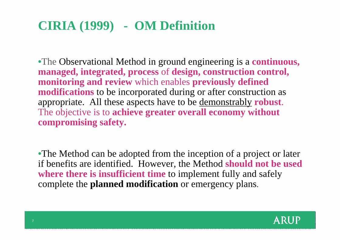
CIRIA (1999) - OM Definition
•The Observational Method in ground engineering is a continuous, managed, integrated, process of design, construction control, monitoring and review which enables previously defined modifications to be incorporated during or after construction as appropriate. All these aspects have to be demonstrably robust. The objective is to achieve greater overall economy without compromising safety.
•The Method can be adopted from the inception of a project or later if benefits are identified. However, the Method should not be used where there is insufficient timeto implement fully and safely complete the planned modification or emergency plans.
8
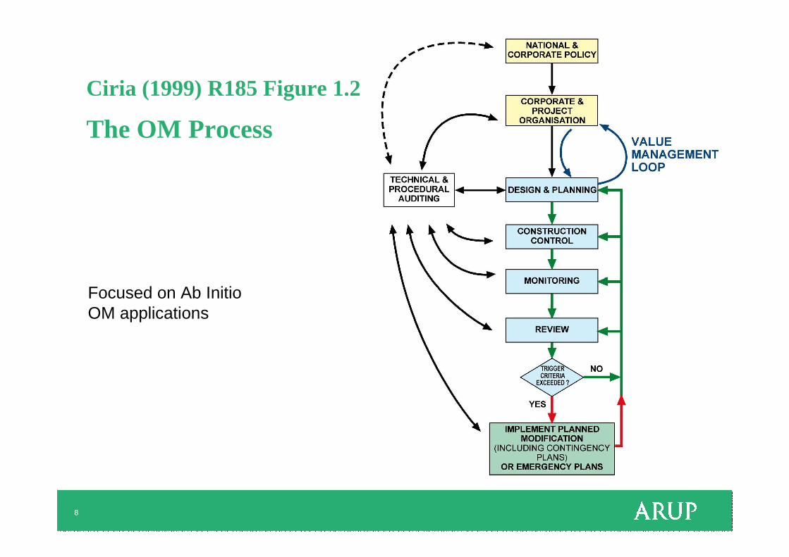
Ciria (1999) R185 Figure 1.2
The OM Process
Focused on Ab InitioOM applications
9
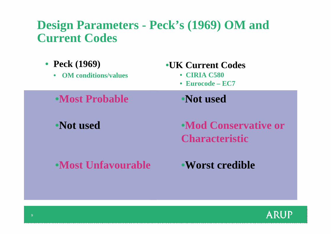
•Not used
•Mod Conservative or Characteristic
•Worst credible
Design Parameters - Peck’s (1969) OM and Current Codes
• Peck (1969)• OM conditions/values
•UK Current Codes• CIRIA C580 • Eurocode – EC7
•Most Probable
•Not used
•Most Unfavourable
10
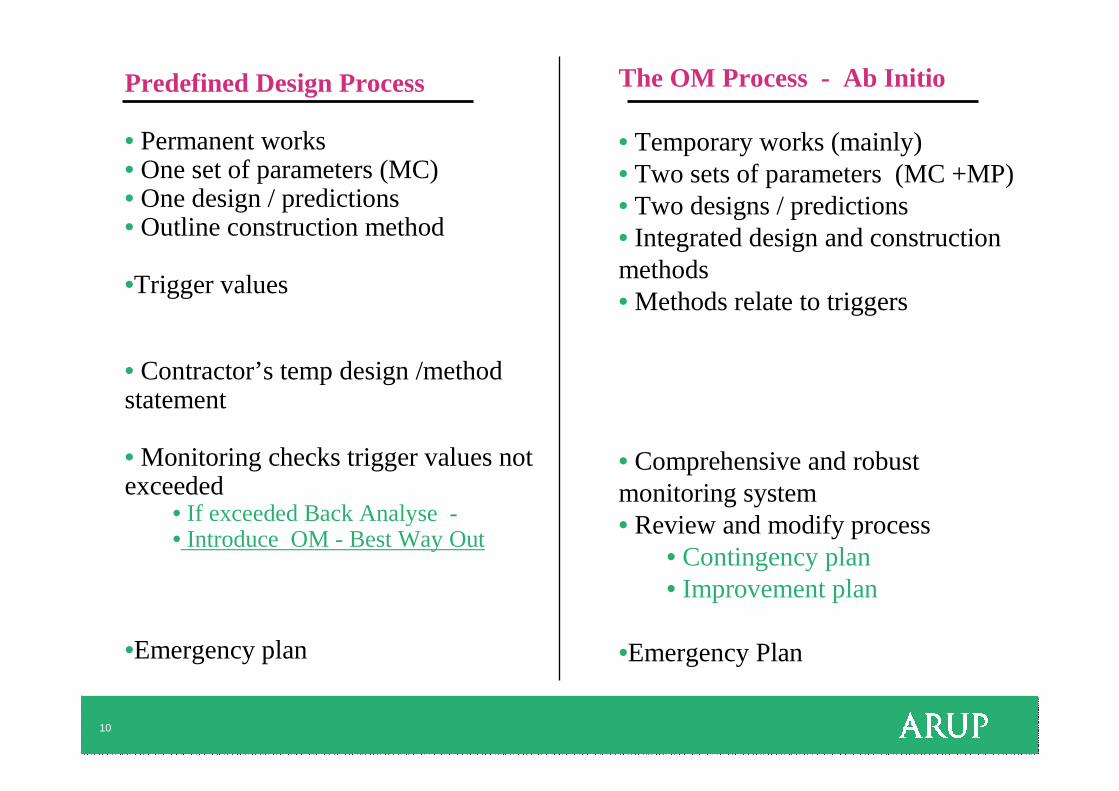
Predefined Design Process
• Permanent works• One set of parameters (MC)• One design / predictions• Outline construction method
•Trigger values
• Contractor’s temp design /method statement
• Monitoring checks trigger values not exceeded
• If exceeded Back Analyse -• Introduce OM - Best Way Out
•Emergency plan
The OM Process - Ab Initio
• Temporary works (mainly)• Two sets of parameters (MC +MP)• Two designs / predictions• Integrated design and construction methods• Methods relate to triggers
• Comprehensive and robust monitoring system • Review and modify process
• Contingency plan• Improvement plan
•Emergency Plan
11
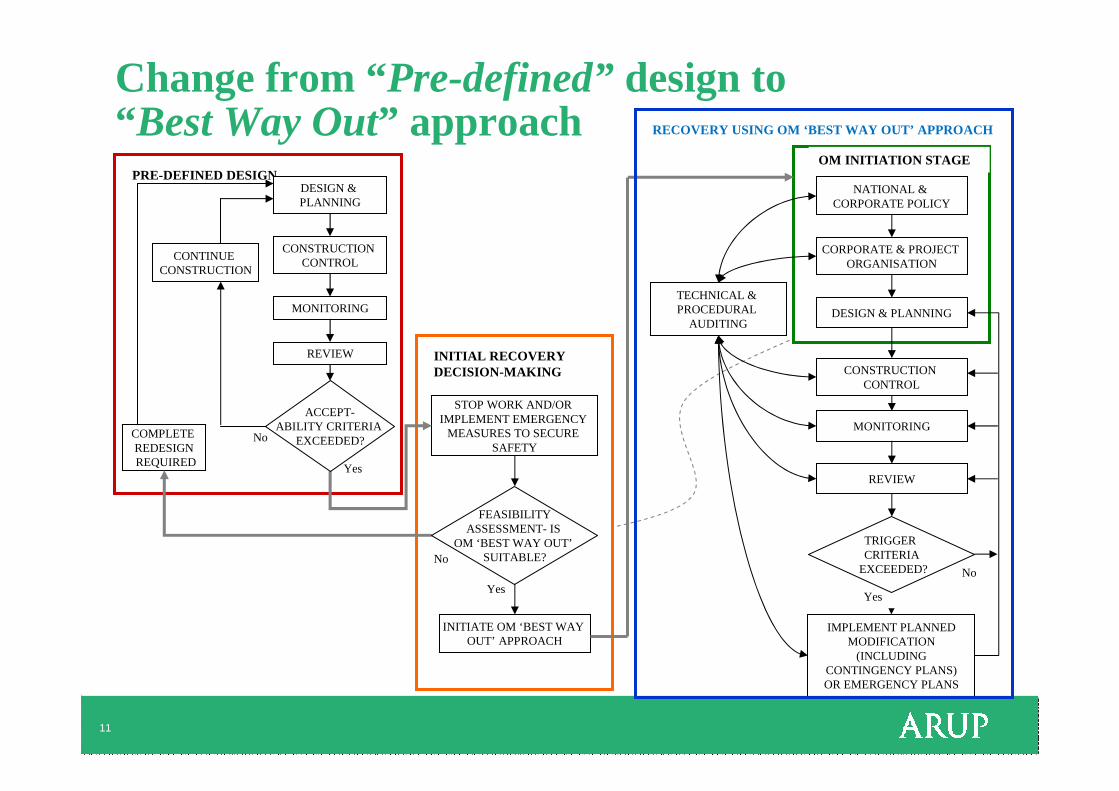
Change from “Pre-defined”design to “ Best Way Out” approach
CONSTRUCTION CONTROL
MONITORING
REVIEW
CONTINUE CONSTRUCTION
COMPLETE REDESIGNREQUIRED
STOP WORK AND/OR IMPLEMENT EMERGENCY
MEASURES TO SECURE SAFETY
INITIATE OM ‘BEST WAY OUT’ APPROACH
CORPORATE & PROJECT ORGANISATION
DESIGN & PLANNING
CONSTRUCTION CONTROL
MONITORING
REVIEW
TECHNICAL & PROCEDURAL
AUDITING
IMPLEMENT PLANNED MODIFICATION
(INCLUDING CONTINGENCY PLANS) OR EMERGENCY PLANS
Yes
No
Yes
NoNo
Yes
OM INITIATION STAGE
INITIAL RECOVERY DECISION-MAKING
PRE-DEFINED DESIGNDESIGN & PLANNING
FEASIBILITY ASSESSMENT- IS
OM ‘BEST WAY OUT’SUITABLE?
TRIGGER CRITERIA
EXCEEDED?
NATIONAL & CORPORATE POLICY
RECOVERY USING OM ‘BEST WAY OUT’ APPROACH
ACCEPT-ABILITY CRITERIA
EXCEEDED?
12
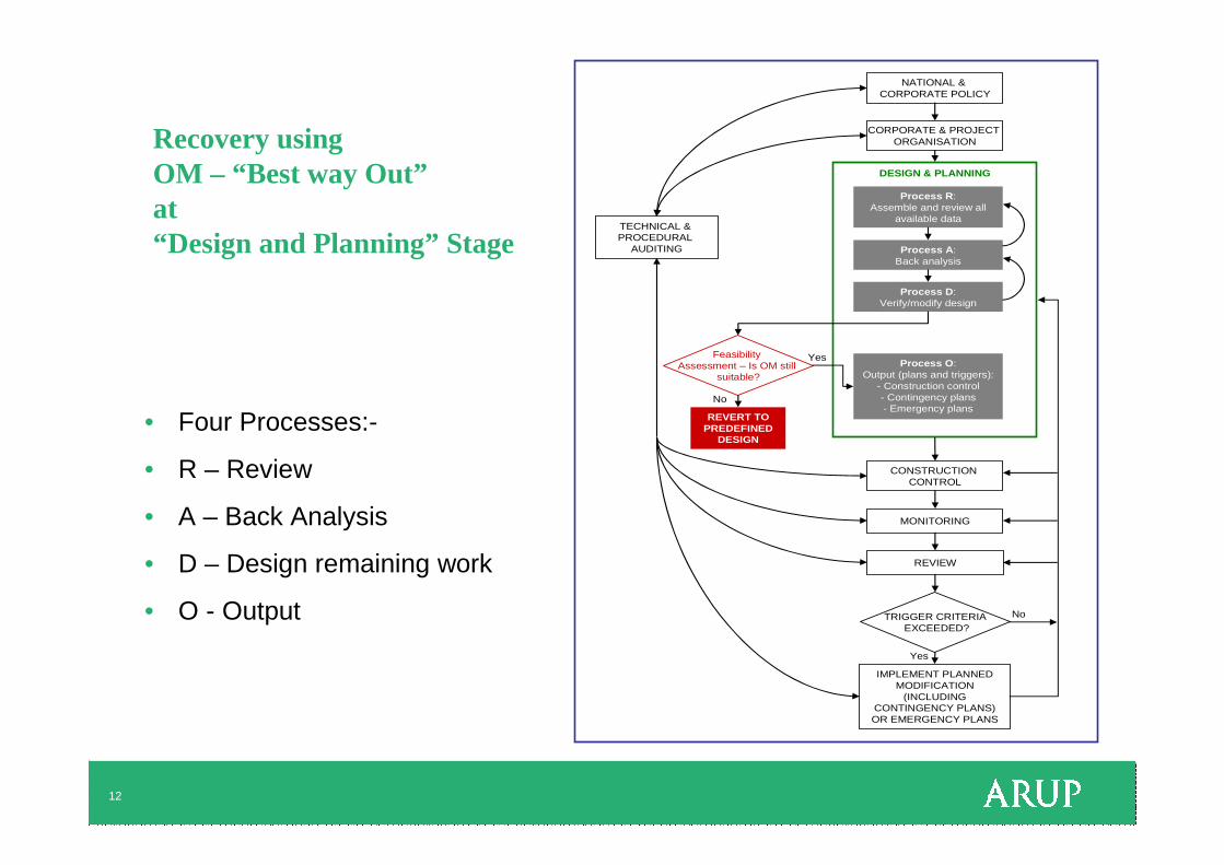
Recovery using OM – “Best way Out”at “Design and Planning” Stage
• Four Processes:-
• R – Review
• A – Back Analysis
• D – Design remaining work
• O - Output
NATIONAL & CORPORATE POLICY
CORPORATE & PROJECT ORGANISATION
DESIGN & PLANNING
CONSTRUCTION CONTROL
MONITORING
REVIEW
TRIGGER CRITERIAEXCEEDED?
TECHNICAL & PROCEDURAL
AUDITING
IMPLEMENT PLANNED MODIFICATION
(INCLUDING CONTINGENCY PLANS) OR EMERGENCY PLANS
No
Yes
Process R: Assemble and review all
available data
Process A: Back analysis
Process D: Verify/modify design
Process O: Output (plans and triggers):
- Construction control- Contingency plans- Emergency plans
Feasibility Assessment – Is OM still
suitable?
REVERT TOPREDEFINED
DESIGN
No
Yes
13
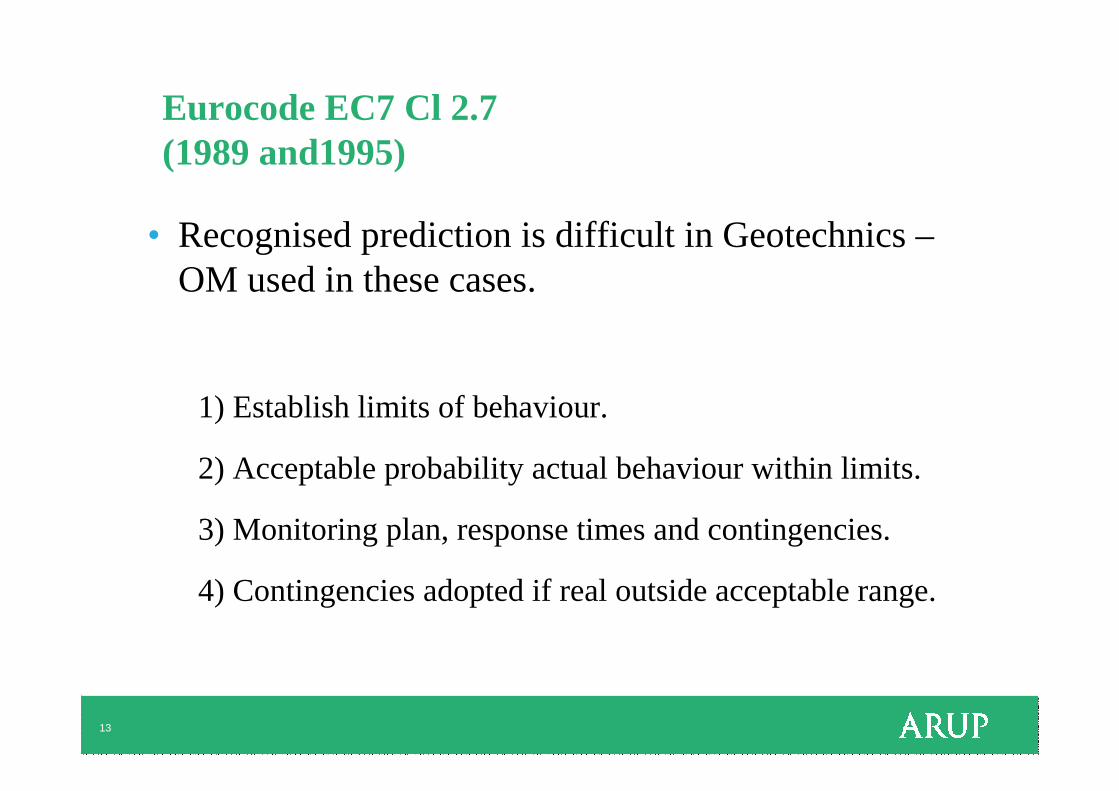
Eurocode EC7 Cl 2.7 (1989 and1995)
• Recognised prediction is difficult in Geotechnics –OM used in these cases.
1) Establish limits of behaviour.
2) Acceptable probability actual behaviour within limits.
3) Monitoring plan, response times and contingencies.
4) Contingencies adopted if real outside acceptable range.

14
UK Design Codes - Soil Strength Parameters
mo
de
rate
ly c
on
se
rva
tiv
e
Soil Strength Parameter Results
No
of
Re
ad
ing
s
1 in 21 in 201 in 1000
Mo
st
Pro
ba
ble
Ch
ara
cte
ris
tic
ma
teri
al
pro
pe
rty
(us
ed
in
str
uc
tura
l e
ng
ine
eri
ng
)
Mo
st
Un
fav
ou
rab
le
(Eg Undrained strength, SPT etc)

15
Ideal EC7 Predicted versus Measured Performance
No
. of
read
ing
s
Deflection ( δ δ δ δ )
"Ideal" distribution ofmeasured deflections
Predicted EC7Characteristic
Value (SLS)
5%
δδδδ
Predicted mostprobable value
Most Unfavourable(ULS)
16
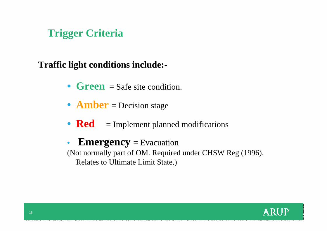
Trigger Criteria
Traffic light conditions include:-
• Green = Safe site condition.
• Amber = Decision stage
• Red = Implement planned modifications
• Emergency = Evacuation(Not normally part of OM. Required under CHSW Reg (1996).
Relates to Ultimate Limit State.)

17
Ideal EC7 Predicted versus Measured Performance
No
. of
read
ing
s
Deflection ( δ δ δ δ )
"Ideal" distribution ofmeasured deflections
Predicted EC7Characteristic
Value (SLS)
5%
δδδδ
Predicted mostprobable value
GREENAMBER
RED
Most Unfavourable(ULS)
Amber trigger -decision
Triggerimplement

18
Ciria (1999) Fig 3.13 Multi Stage Excavation

19
HSE ‘Discovery – Recovery’ Modeleg for tunnelling
From HSE, 1996
Red trigger
Ambertrigger

20
Case Histories
• Kings Place - London
• Nicol Highway Collapse - Singapore
• Canary Wharf – Crossrail Staion Box
• Donegall Quay - CFA piles

Kings Place – OM – Ab initio
• Damage assessment trigger‒ 50mm max wall deflection
• Diaphragm Wall ‒ 1.0m thick
• 1 level of temporary corner props
• 16m retained height
• Observational Method
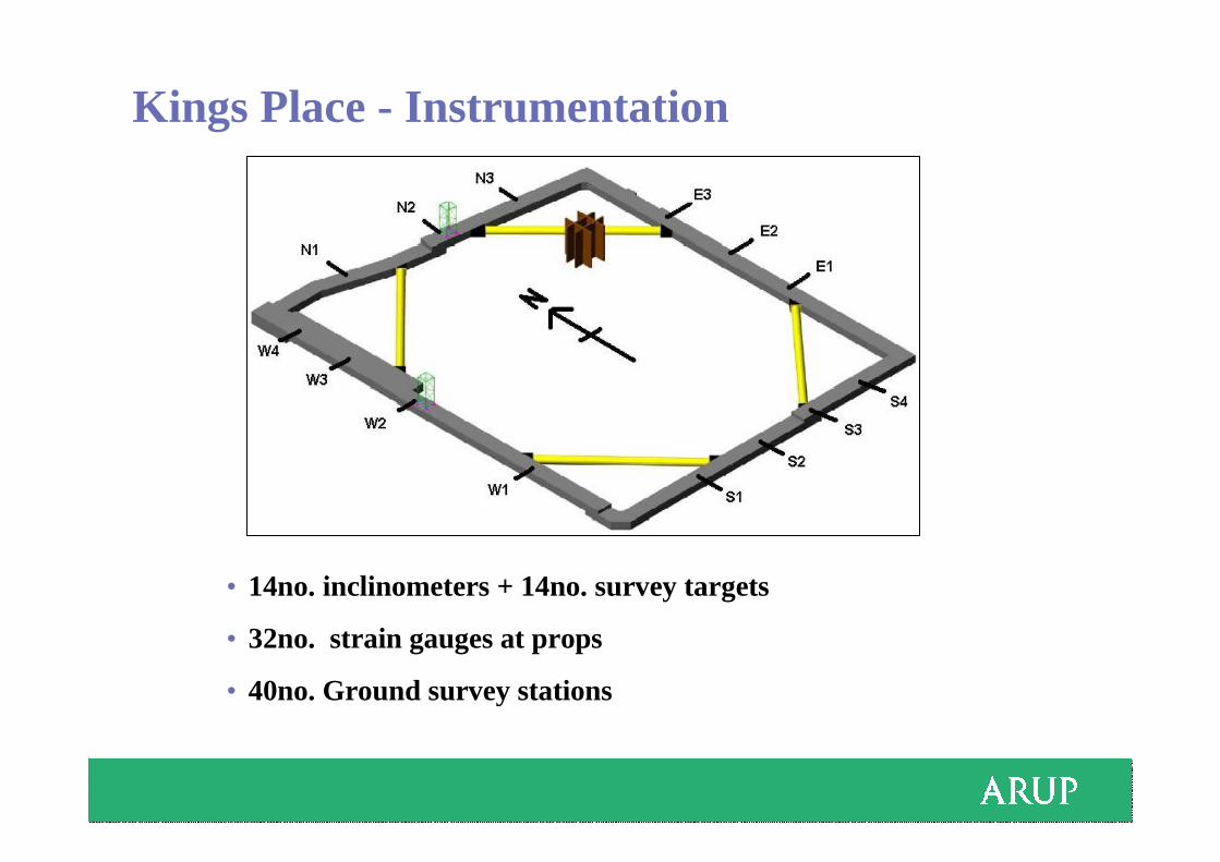
Kings Place - Instrumentation
• 14no. inclinometers + 14no. survey targets
• 32no. strain gauges at props
• 40no. Ground survey stations
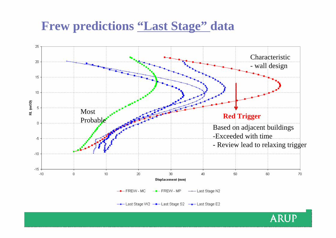
Frew predictions “Last Stage” data
Legend
Red Trigger
Based on adjacent buildings-Exceeded with time- Review lead to relaxing trigger
Characteristic- wall design
MostProbable
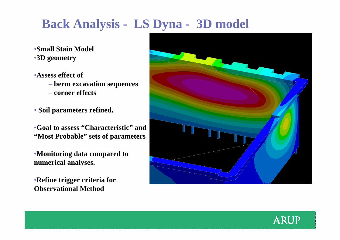
Back Analysis - LS Dyna - 3D model
•Small Stain Model•3D geometry
•Assess effect of ‒ berm excavation sequences‒ corner effects
• Soil parameters refined.
•Goal to assess “Characteristic” and “Most Probable” sets of parameters
•Monitoring data compared to numerical analyses.
•Refine trigger criteria for Observational Method

Analysis Summary
Inc E2
• Approx 600,000 elements in 32 material sets.
• 5 Analyses varying:-‒Soil parameter.‒ Suction limits.
• Stages representing 8 steps of excavation modelled.
• Site data compared to model data. Vertical movement during
excavation stage.
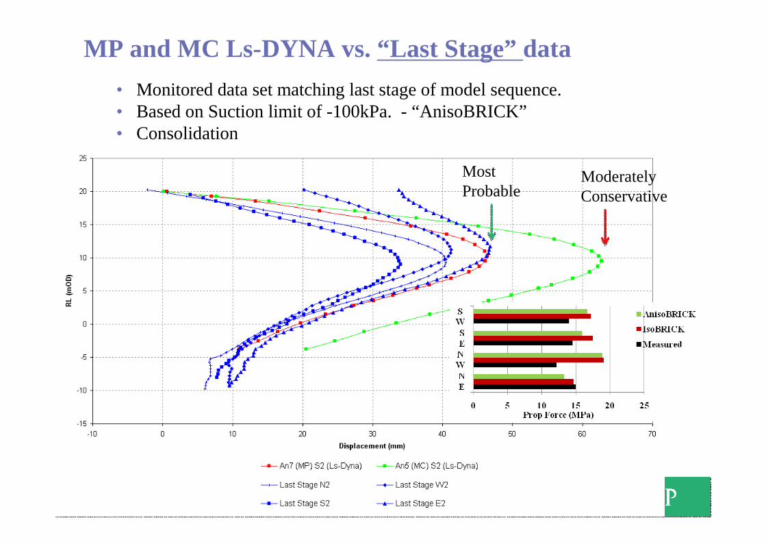
• Monitored data set matching last stage of model sequence.• Based on Suction limit of -100kPa. - “AnisoBRICK”• Consolidation
MP and MC Ls-DYNA vs. “Last Stage” data
Most Probable
Moderately Conservative
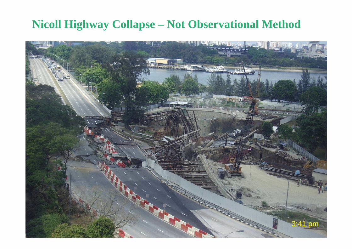
3:41 pm
Nicoll Highway Collapse – Not Observational Method
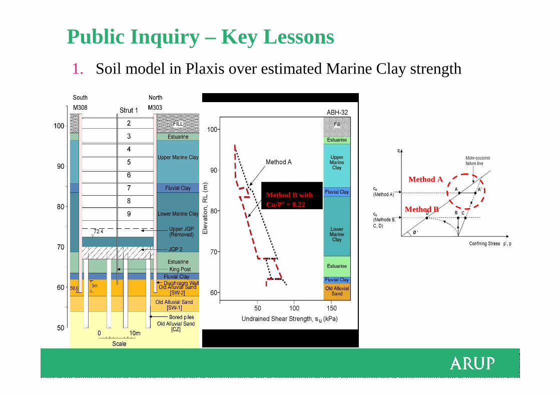
Public Inquiry – Key Lessons1. Soil model in Plaxis over estimated Marine Clay strength
Method A
Method B
Method B with Cu/P’ = 0.22

Key Lessons cont’d
2. Waler connection under capacity
Many other Contributory Factors
• Monitoring and review regime – not effective
• Back analysis process – not rigorous
Method A
Method B
Web StiffenerDesign load = 6000kN
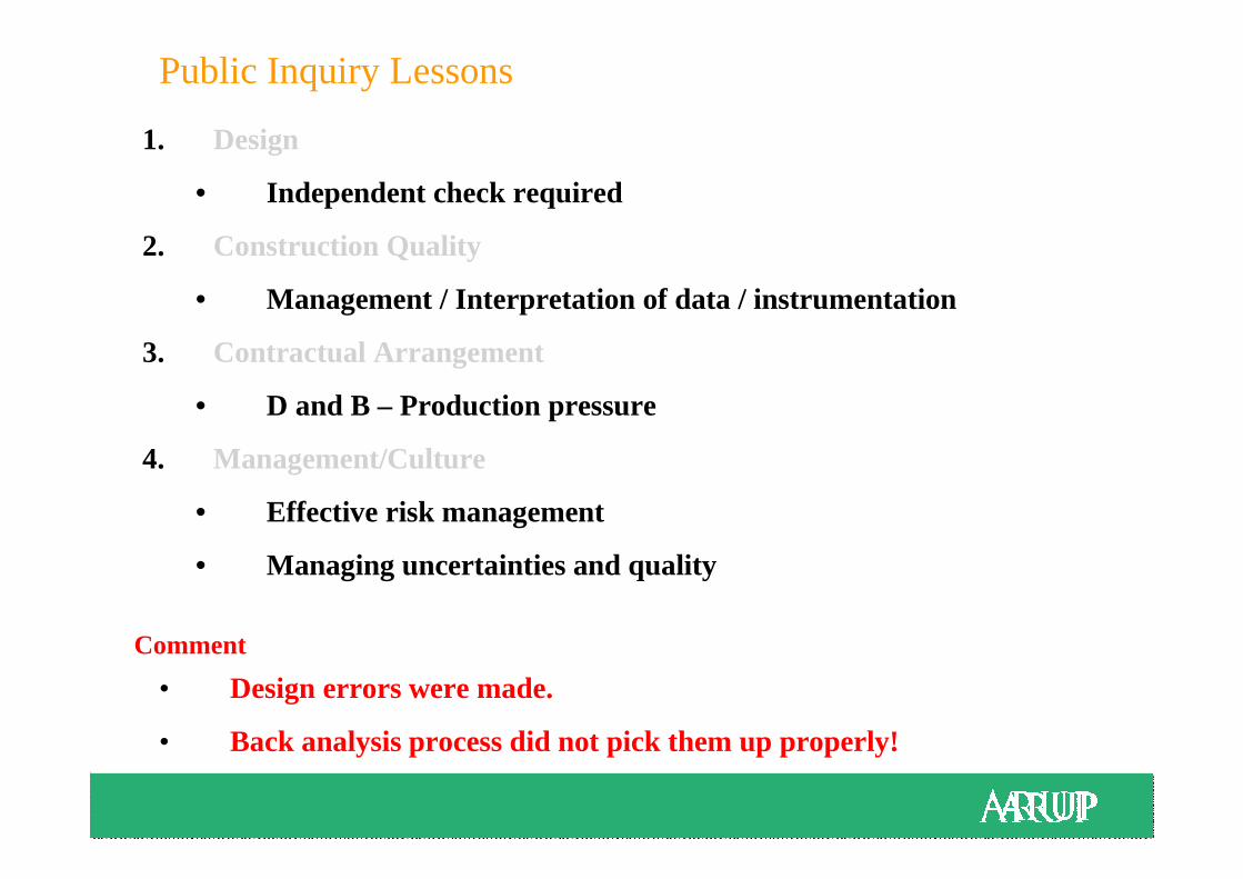
1. Design
• Independent check required
2. Construction Quality
• Management / Interpretation of data / instrumentation
3. Contractual Arrangement
• D and B – Production pressure
4. Management/Culture
• Effective risk management
• Managing uncertainties and quality
Public Inquiry Lessons
Comment
• Design errors were made.
• Back analysis process did not pick them up properly!
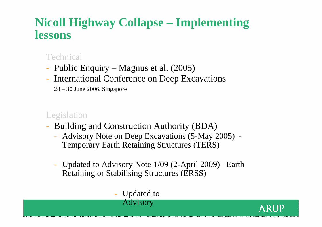
Nicoll Highway Collapse – Implementing lessons
Technical- Public Enquiry – Magnus et al, (2005)- International Conference on Deep Excavations
28 – 30 June 2006, Singapore
Legislation - Building and Construction Authority (BDA)
- Advisory Note on Deep Excavations (5-May 2005) -Temporary Earth Retaining Structures (TERS)
- Updated to Advisory Note 1/09 (2-April 2009)– Earth Retaining or Stabilising Structures (ERSS)
- Updated to Advisory
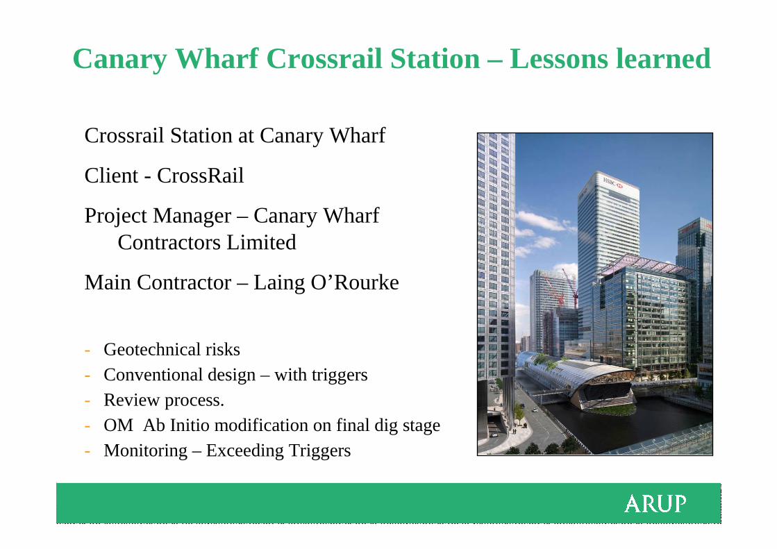
Canary Wharf Crossrail Station – Lessons learned
Crossrail Station at Canary Wharf
Client - CrossRail
Project Manager – Canary Wharf Contractors Limited
Main Contractor – Laing O’Rourke
- Geotechnical risks- Conventional design – with triggers- Review process.- OM Ab Initio modification on final dig stage- Monitoring – Exceeding Triggers

Canary Wharf Crossrail Station Layout
Geotech risks:-Adjacent buildingsDock structuresDLR
Add chalk
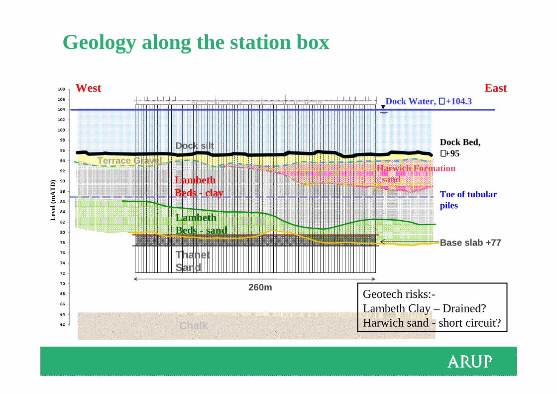
Geology along the station box
West EastDock Water, ∼∼∼∼ +104.3
LambethBeds - sand
Terrace Gravel
Dock silt
Leve
l (m
AT
D)
ThanetSand
Lambeth Beds - clay
260m
Chalk
Toe of tubular piles
Dock Bed, ∼∼∼∼+95
Base slab +77
Harwich Formation - sand
Geotech risks:-Lambeth Clay – Drained?Harwich sand - short circuit?
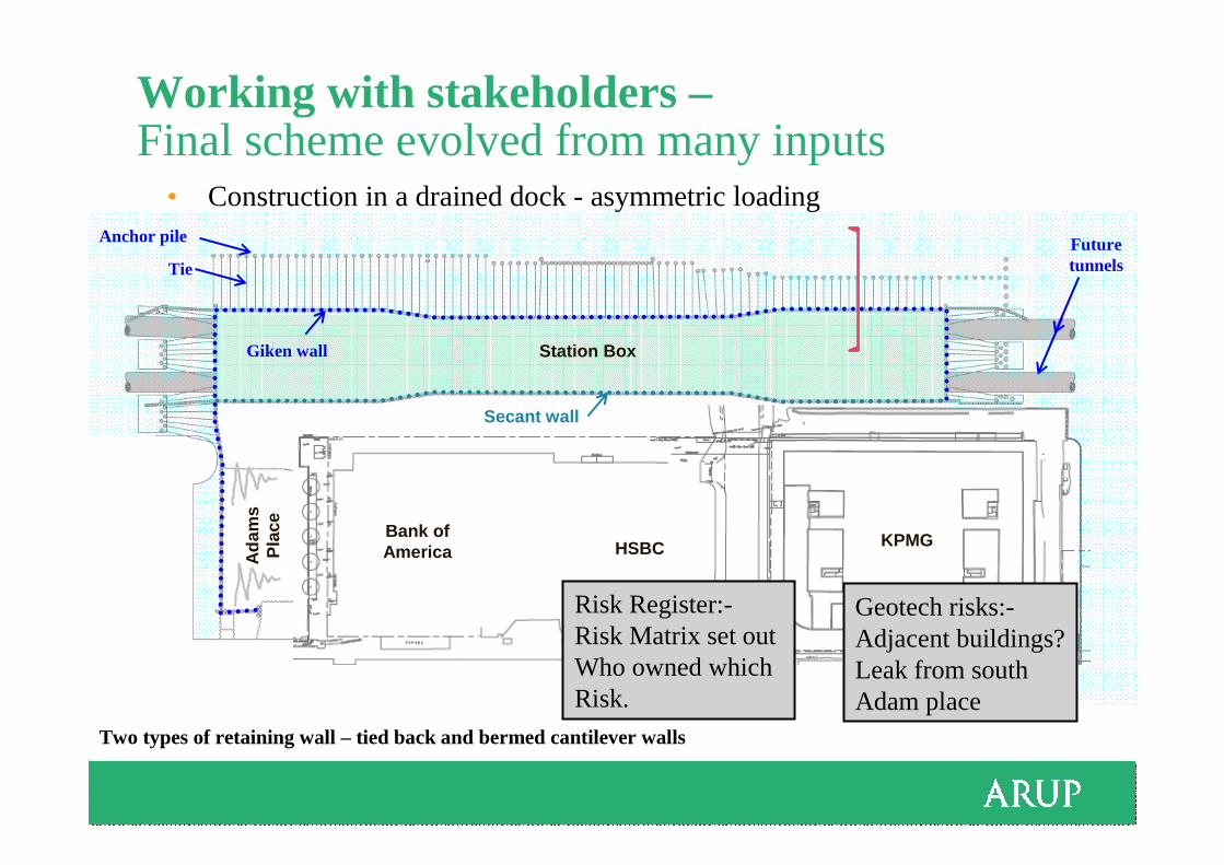
Working with stakeholders –Final scheme evolved from many inputs
Bank of America HSBC
KPMGBank of America HSBC KPMG
Station Box
Ad
ams
Pla
ce
Two types of retaining wall – tied back and bermed cantilever walls
Anchor pile
• Construction in a drained dock - asymmetric loading
Future tunnelsTie
Giken wall
Secant wall
Geotech risks:-Adjacent buildings?Leak from southAdam place
Risk Register:-Risk Matrix set out Who owned which Risk.
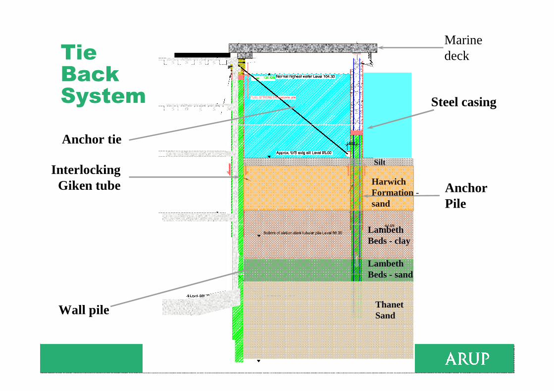
Tie Back System
Anchor Pile
Anchor tie
Wall pile
Interlocking Giken tube
Steel casing
Marine deck
Lambeth Beds - clay
Thanet Sand
Silt
Lambeth Beds - sand
Harwich Formation -sand

Soil-structure interaction – finite element modelExaggerated Plaxis displacement plot
Finite element method – capturing out-of-balance loading (sway) and ground movement
Chalk
Thanet Sand
Billingsgate Market
North DockStation Box
Existing CofferdamKPMG
Building
Lambeth Beds
Harwich FormationTerrace Gravel
SOUTH NORTH
Geotech risks:-Adjacent buildings?
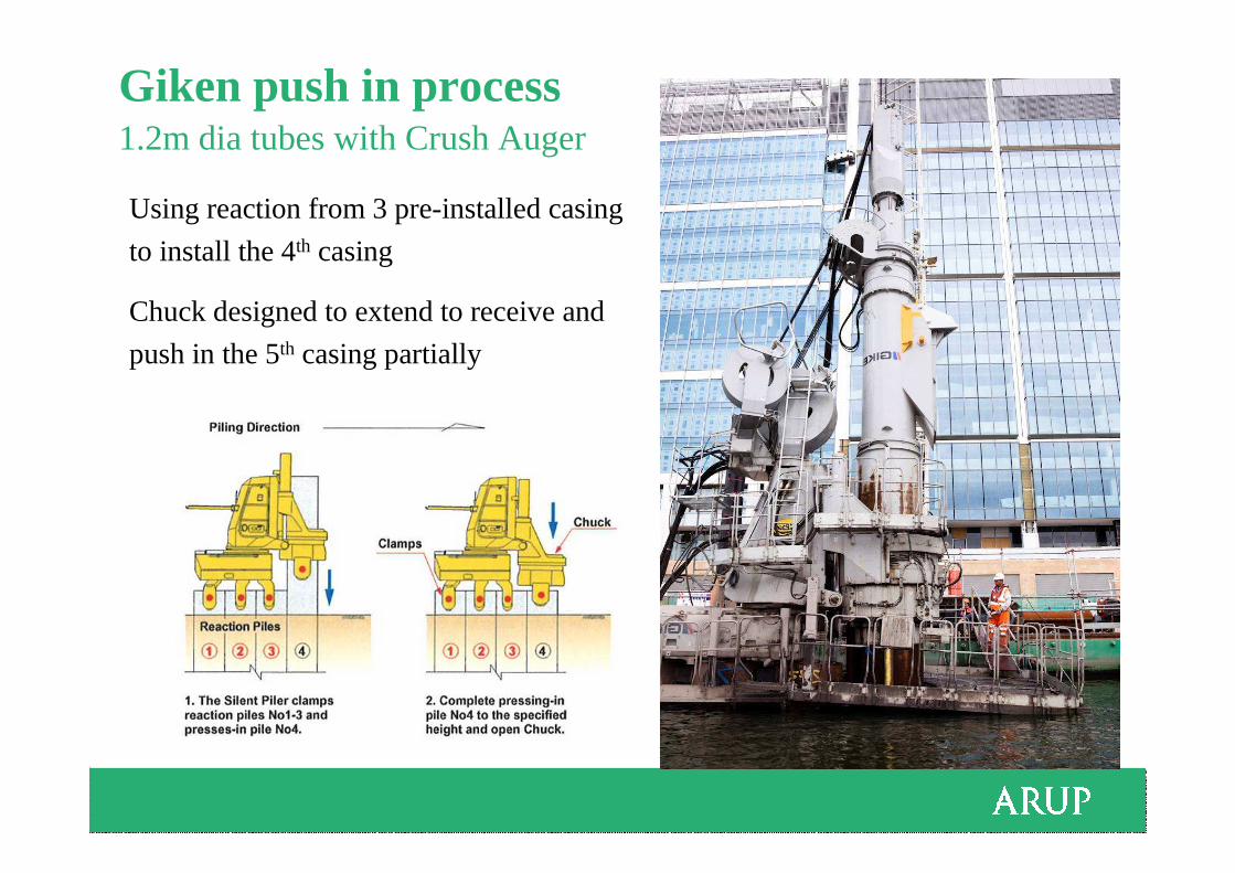
Giken push in process1.2m dia tubes with Crush Auger
Using reaction from 3 pre-installed casing
to install the 4th casing
Chuck designed to extend to receive and
push in the 5th casing partially
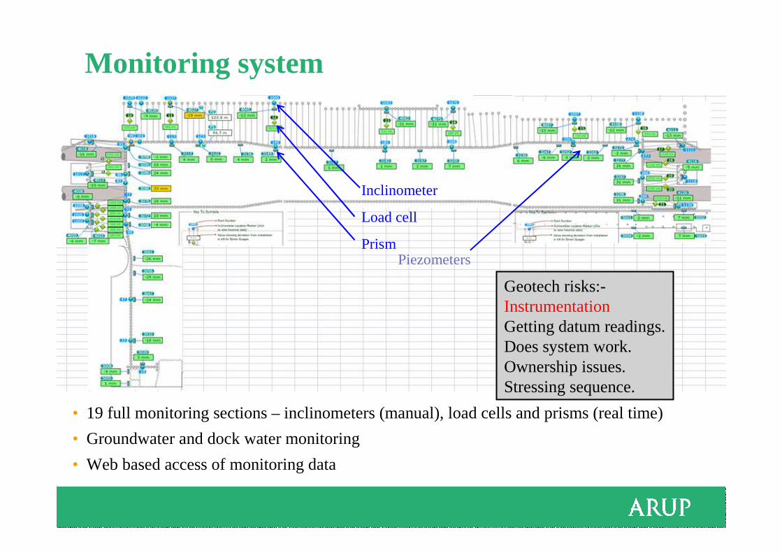
Monitoring system
• 19 full monitoring sections – inclinometers (manual), load cells and prisms (real time)
• Groundwater and dock water monitoring
• Web based access of monitoring data
Inclinometer
Load cell
Prism
Geotech risks:-InstrumentationGetting datum readings.Does system work.Ownership issues.Stressing sequence.
Piezometers
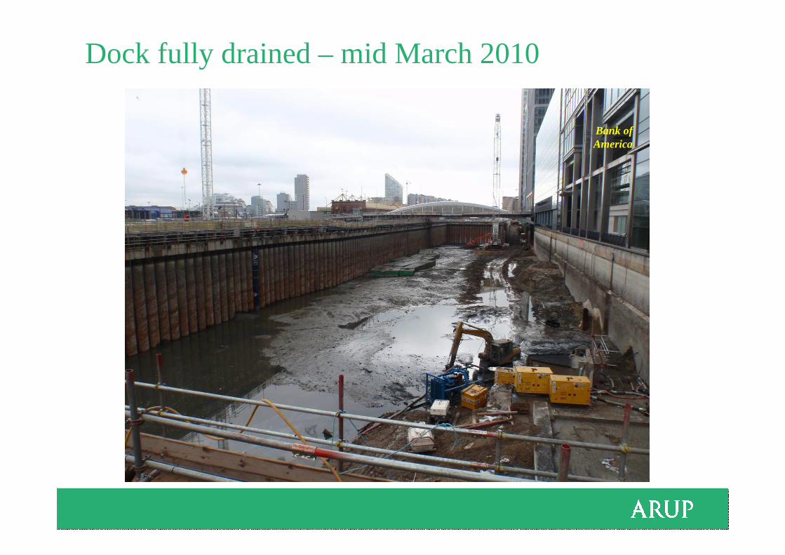
Dock fully drained – mid March 2010
Bank of America
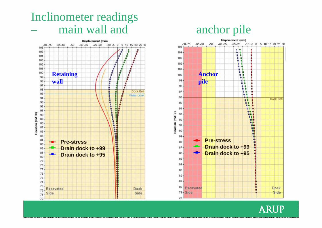
Inclinometer readings – main wall and anchor pile
Pre-stressDrain dock to +99Drain dock to +95
Pre-stressDrain dock to +99Drain dock to +95
Retaining wall
Anchor pile
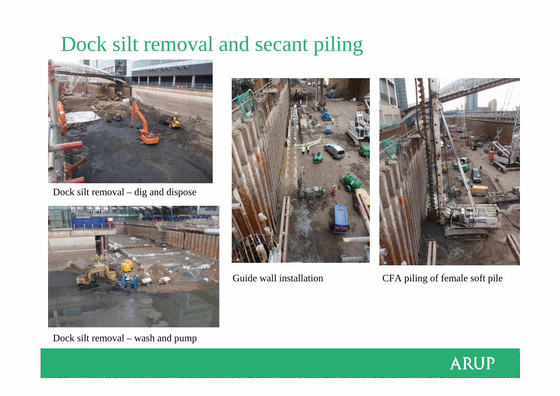
Dock silt removal and secant piling
Dock silt removal – dig and dispose
Dock silt removal – wash and pump
Guide wall installation CFA piling of female soft pile
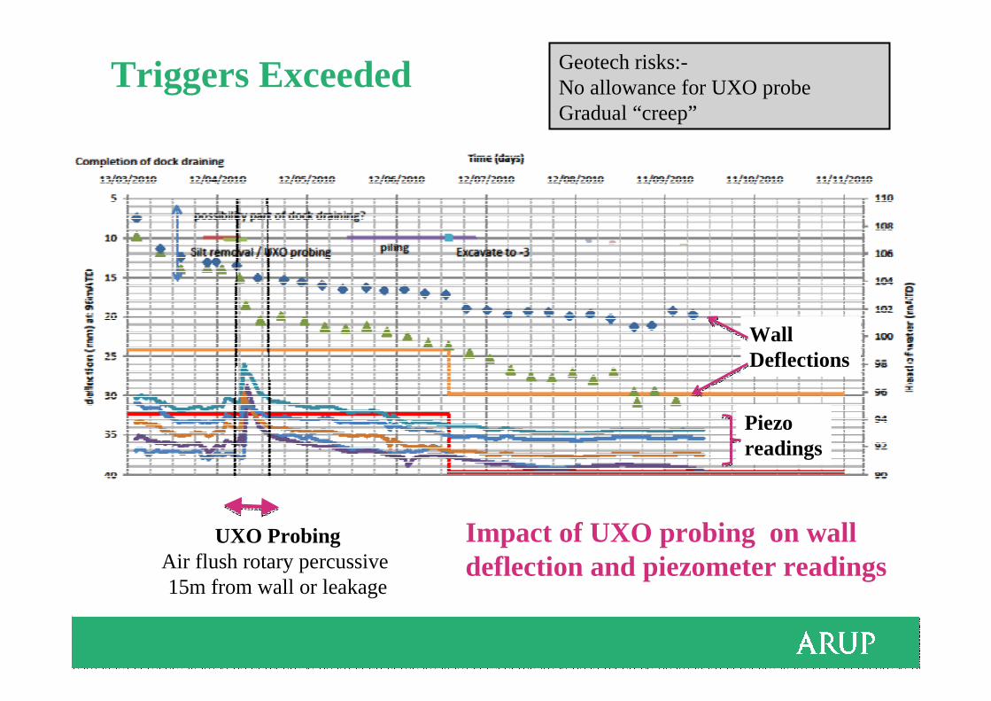
Triggers Exceeded
Piezo readings
WallDeflections
UXO ProbingAir flush rotary percussive 15m from wall or leakage
Impact of UXO probing on wall deflection and piezometer readings
Geotech risks:-No allowance for UXO probeGradual “creep”

Plunge column installationColumn tolerances
- +/- 25mm in plan- 1 in 400 verticality
Pile tolerances
- +/- 25mm in plan- 1 in 75 verticality
Precast guide hole for 2.1m pile Plunge column guide frame installation
Plunge column installation (18m long, upto 27t)
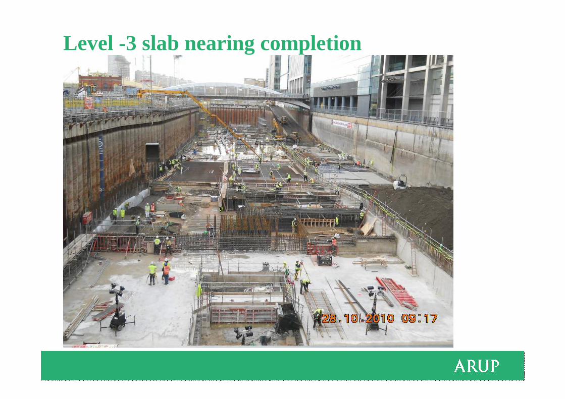
Level -3 slab nearing completion
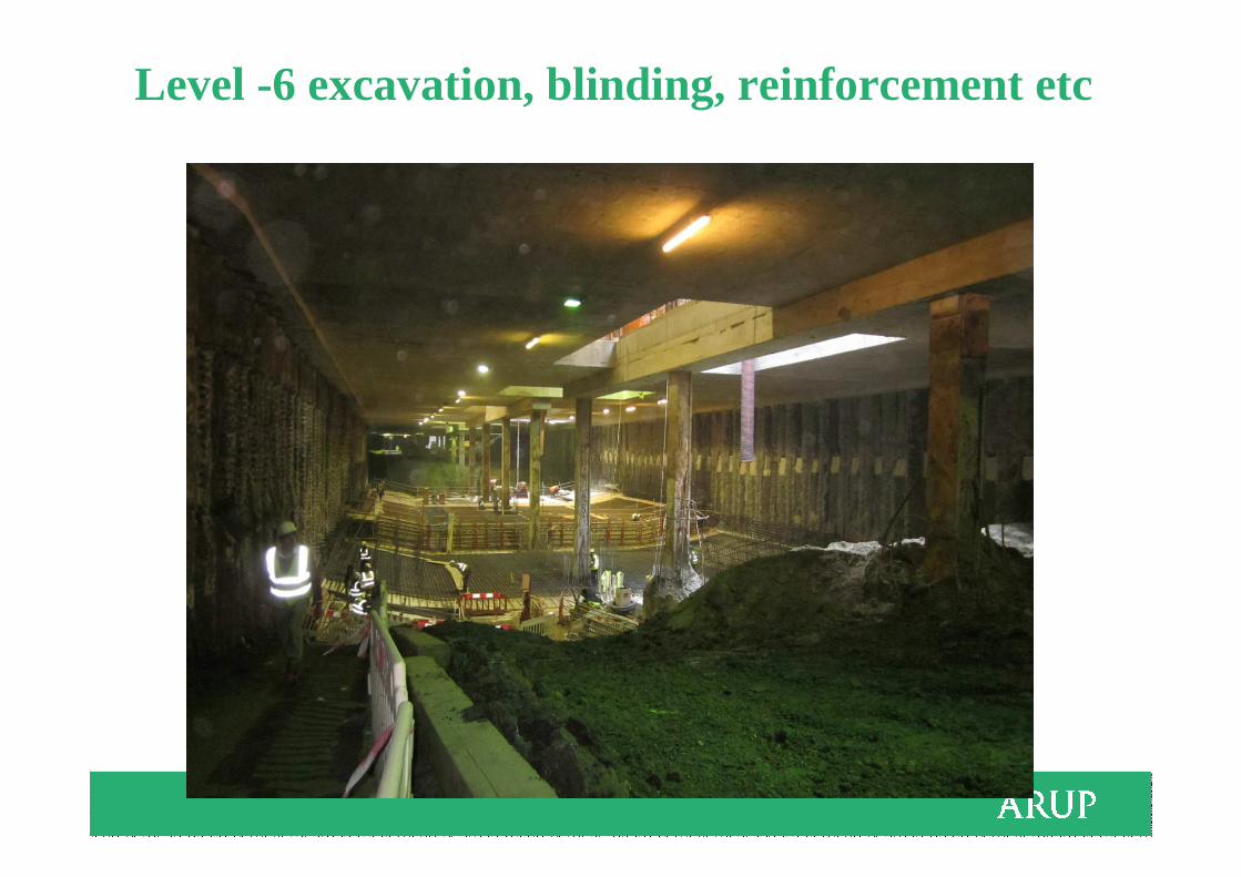
Level -6 excavation, blinding, reinforcement etc

OM – Best Way Out –Review and Modify soil parameters
Bank of America HSBC
KPMGBank of America HSBC
KPMG
Station Box
Ada
ms
Pla
ceEast headwallWest headwall
• Tunnel alignment prevented evenly spread of anchor piles
Future tunnels
Anchor piles outside tunnel alignment

Back analyse Review soil parametersRedesign - Remove berm and intermediate props OM – Best Way Out – New triggers
• The 2D simplified design approach verified using a 3D model when a revised construction sequence was proposed
Anchor piles staggered and outside tunnel
alignment

River
Highway
Railway
A
A
Listed Building
Donegal Quay Development TheSite
B
B
Footprint Area ~ 35 m x 140 m

Ground Conditions – Geotechnical Profile
River
-52
WT=~1.0mMADE GROUND
SLEECH / ALLUVIUM
?SANDSTONE
SAND (GLACIAL)
SILTY CLAY / CLAY (GLACIAL)
+1.8
-6
-12.5
-53
+3.5

Soil properties
SLEECH
GLACIAL SAND
GLACIAL CLAY
-6
-12.5
SAND
(Medium dense)
-6
-12.5
Undrained Strength (kPa)SPT Profile
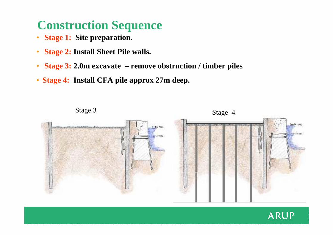
Construction Sequence • Stage 1: Site preparation.
• Stage 2:Install Sheet Pile walls.
• Stage 3:2.0m excavate – remove obstruction / timber piles
• Stage 4: Install CFA pile approx 27m deep.
Stage 3 Stage 4
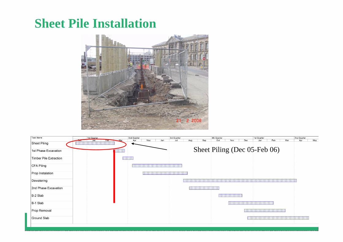
Sheet Pile Installation
Sheet Piling (Dec 05-Feb 06)

Phase 1 Excavation to +1.5 mOD
Excavation (March 06)

Inclinometers 14 March 2006 - Cantilever dig
3
4
5
6
2
Inclinometer 4
Inclinometer 5
Deflection 28mm
Deflection 15mm

Timber Pile Extraction
Timber Pile Extraction (April 06)
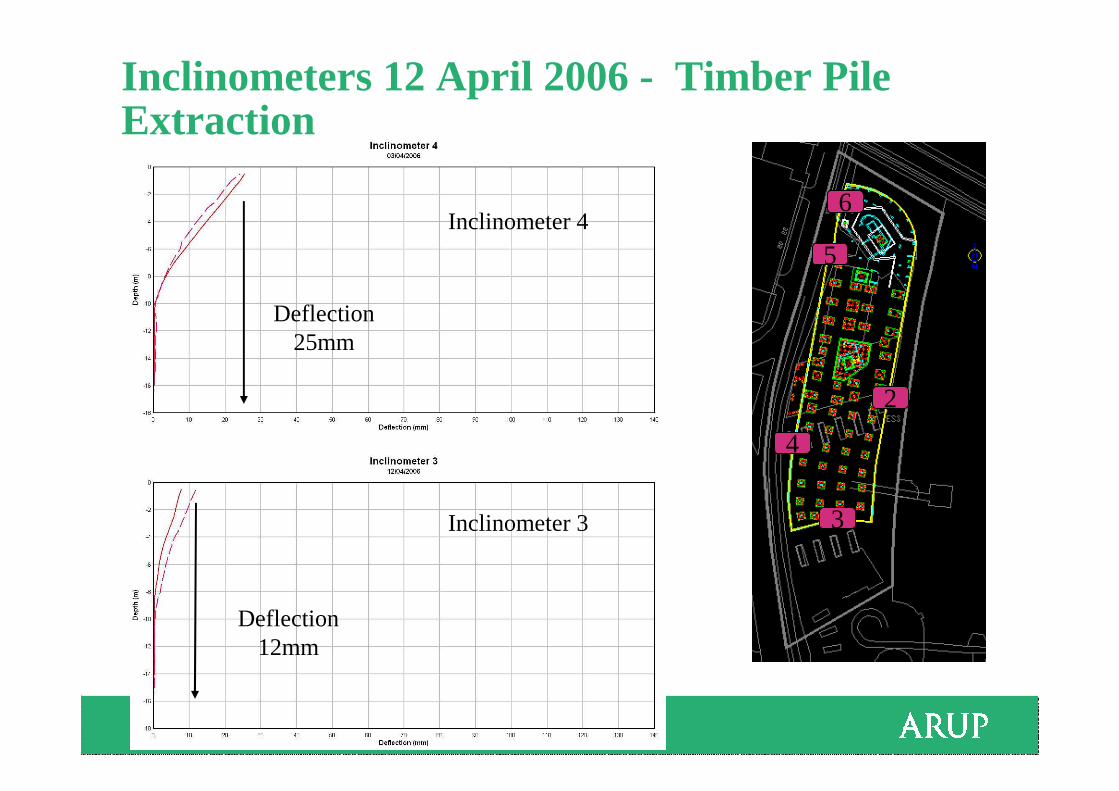
Inclinometers 12 April 2006 - Timber Pile Extraction
3
4
5
6
2
Inclinometer 3
Deflection 12mm
Inclinometer 4
Deflection 25mm
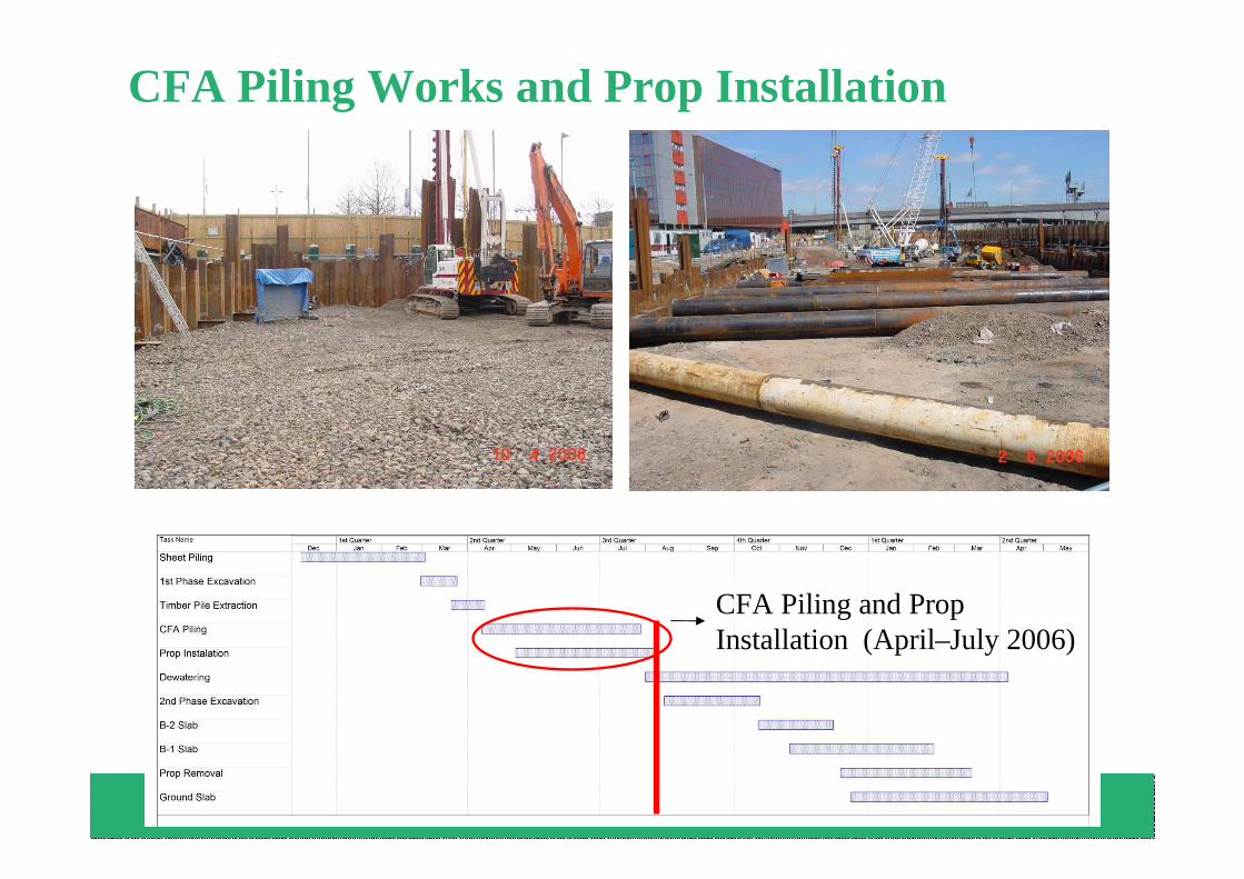
CFA Piling Works and Prop Installation
CFA Piling and Prop Installation (April–July 2006)

Inclinometers - 02 May 2006 - CFA Flighting of Sleech
3
4
5
6
2
Inclinometer 4
(With rotation during concreting)
Inclinometer 5
(Without rotation during concreting )
Deflection 75mmSand
Sleech
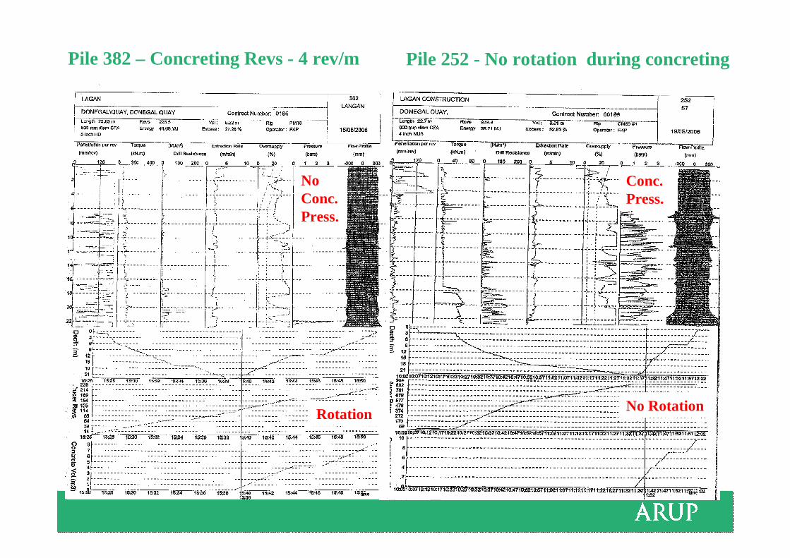
Pile 252 - No rotation during concretingPile 382 – Concreting Revs - 4 rev/m
Rotation No Rotation
Conc.Press.
NoConc.Press.
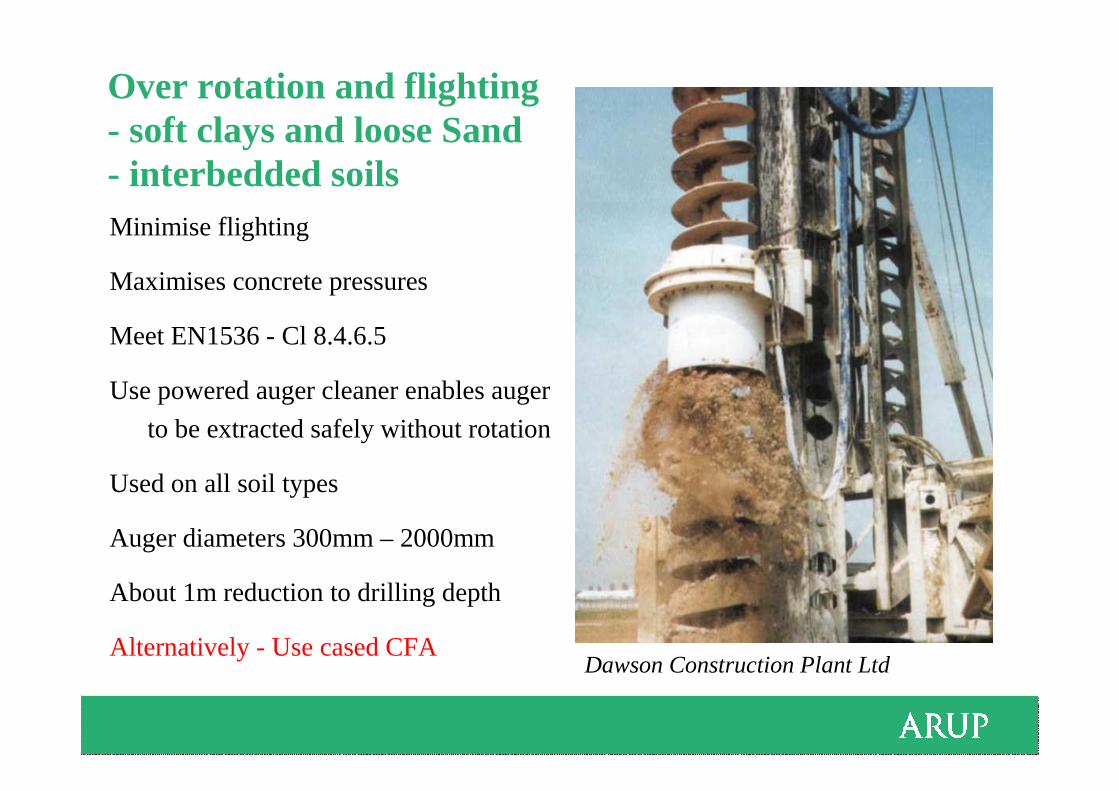
Over rotation and flighting - soft clays and loose Sand- interbedded soils Minimise flighting
Maximises concrete pressures
Meet EN1536 - Cl 8.4.6.5
Use powered auger cleaner enables auger
to be extracted safely without rotation
Used on all soil types
Auger diameters 300mm – 2000mm
About 1m reduction to drilling depth
Alternatively - Use cased CFADawson Construction Plant Ltd
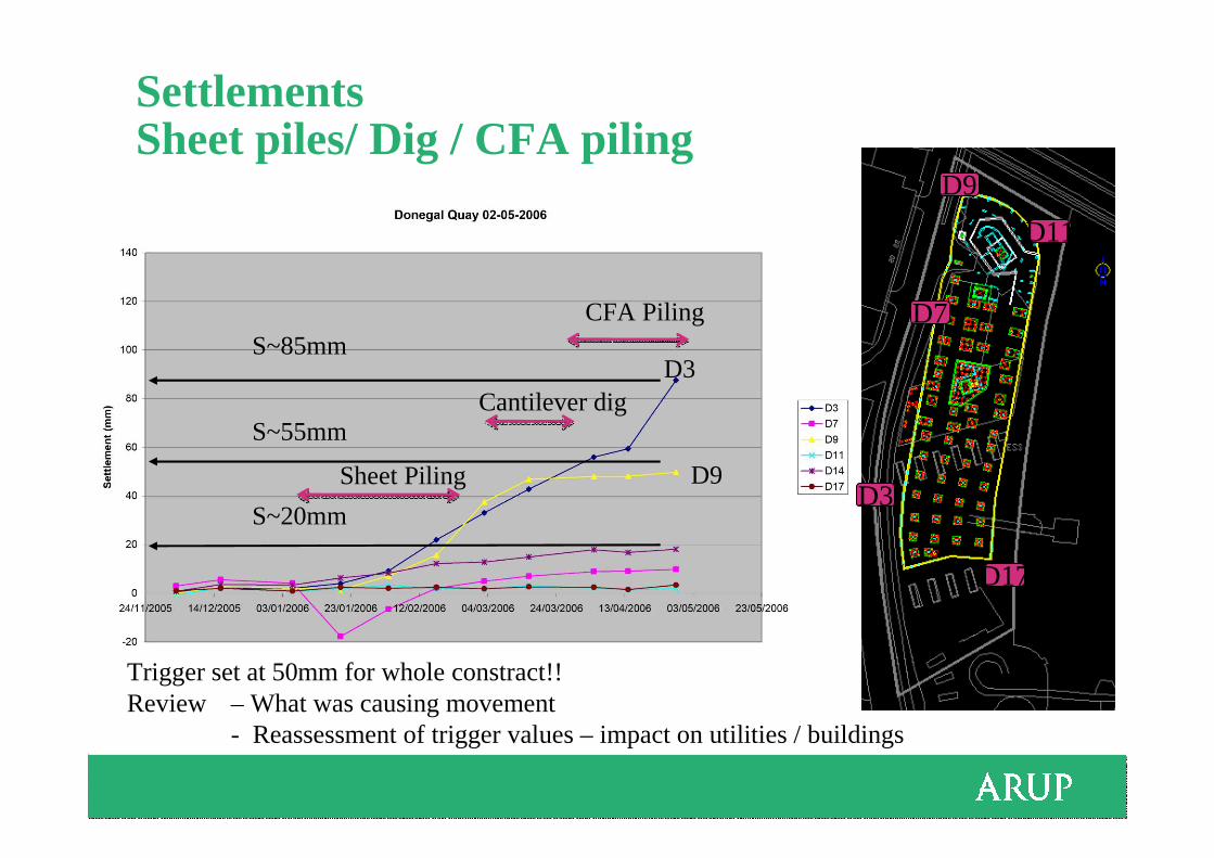
Settlements Sheet piles/ Dig / CFA piling
D17
D3
D7
D9
D11
S~85mm
S~55mm
S~20mm
D3
D9
Cantilever dig
CFA Piling
Sheet Piling
Trigger set at 50mm for whole constract!!Review – What was causing movement
- Reassessment of trigger values – impact on utilities / buildings

Donegall Quay Comments
Construction processes cause ground movments
• Wall installation
• Pile installation
• Anchor installation
Specify limits and incorporate into movement calculations
• Amber trigger= 3mm
• Red trigger= 5mm
These movements occur rapidly and continuous monitoring required until process is checked!!
64
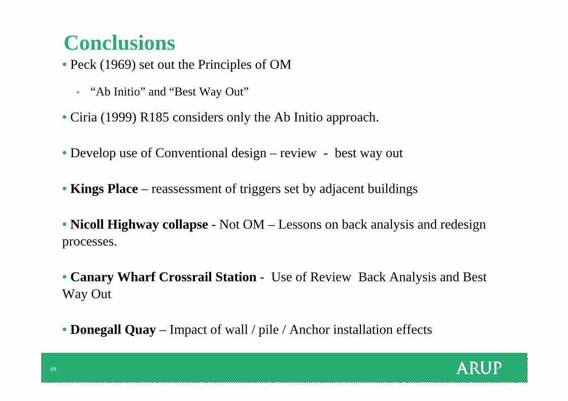
Conclusions• Peck (1969) set out the Principles of OM
• “Ab Initio” and “Best Way Out”
• Ciria (1999) R185 considers only the Ab Initio approach.
• Develop use of Conventional design – review - best way out
• Kings Place – reassessment of triggers set by adjacent buildings
• Nicoll Highway collapse - Not OM – Lessons on back analysis and redesign processes.
• Canary Wharf Crossrail Station - Use of Review Back Analysis and Best Way Out
• Donegall Quay – Impact of wall / pile / Anchor installation effects

65
Thank you for your attention.
Any Questions?