use of the application program - image.schrackcdn.com
TRANSCRIPT

GAMMA instabus
Application program description
September 2017
07 B0 A4 Switching Actuator 4-fold 9A010107 B0 A8 Switching Actuator 8-fold 9A020107 B0 A12 Switching Actuator 12-fold 9A0301
Siemens AG DS02 Update: http://www.siemens.com/gamma-tdBuilding Technologies DivisionControl Products and Systems Siemens AG 2017
P.O. Box 10 09 53, D-93009 Regensburg Subject to change without further notice 1/62
Table of contents
Use of the application program ...................................................................................................................................................11. Functional description .............................................................................................................................................................3
Behavior at bus voltage failure / recovery ................................................................................................................................5Building site function ................................................................................................................................................................5Factory default state .................................................................................................................................................................5Behavior on unloading the application program .....................................................................................................................5Resetting the device to factory default settings.......................................................................................................................5
2. Communication objects ...........................................................................................................................................................63. Device Settings .........................................................................................................................................................................84. Channel settings ................................................................................................................................................................... 10
Control Value Input ................................................................................................................................................................ 14Normal mode ......................................................................................................................................................................... 18Timer mode ............................................................................................................................................................................ 21Flashing .................................................................................................................................................................................. 26Logic operation ...................................................................................................................................................................... 28Central switching ................................................................................................................................................................... 328-bit scene control ................................................................................................................................................................. 33Night mode ............................................................................................................................................................................ 36Override .................................................................................................................................................................................. 39--- Manual override (ON) ........................................................................................................................................................ 40--- Permanent OFF .................................................................................................................................................................. 42--- Lock .................................................................................................................................................................................... 44--- Central override control..................................................................................................................................................... 46--- User-defined override function ......................................................................................................................................... 48--- Forced control .................................................................................................................................................................... 51Status annunciation ............................................................................................................................................................... 53Counting of switching cycles ................................................................................................................................................. 55Counting of operating hours ................................................................................................................................................. 58
Use of the application program
Application program „07 B0 A4 Switching Actuator 4-fold 9A0101“
Product family: OuptputProduct type: Binary output, 4-foldManufacturer: Siemens
Name: Switching Actuator N530D31Description: Switching Actuator 4x AC 230V, 6AX, C-LoadOrder no.: 5WG1 530-1DB31
Name: Switching Actuator N532D31Description: Switching Actuator 4x AC 230V, 10AX, C-LoadOrder-no.: 5WG1 532-1DB31
Name: Switching Actuator N534D31Description: Switching Actuator 4x AC 230V, 16/20AX, C-LoadOrder no.: 5WG1 534-1DB31

GAMMA instabus
Application program description
September 2017
07 B0 A4 Switching Actuator 4-fold 9A010107 B0 A8 Switching Actuator 8-fold 9A020107 B0 A12 Switching Actuator 12-fold 9A0301
Update: http://www.siemens.com/gamma-td DS02 Siemens AGBuilding Technologies Division
Siemens AG 2017 Control Products and Systems
2/62 Subject to change without further notice P.O. Box 10 09 53, D-93009 Regensburg
Application program „07 B0 A8 Switching Actuator 8-fold 9A0201“
Product family: OutputProduct type: Binary output, 8-foldManufacturer: Siemens
Name: Switching Actuator N530D51Description: Switching Actuator 8x AC 230V, 6AX, C-LoadOrder no.: 5WG1 530-1DB51
Name: Switching Actuator N532D51Description: Switching Actuator 8x AC 230V, 10AX, C-LoadOrder no.: 5WG1 532-1DB51
Name: Switching Actuator N534D51Description: Switching Actuator 8x AC 230V, 16/20AX, C-LoadOrder no.: 5WG1 534-1DB51
Application program „07 B0 A12 Switching Actuator 12-fold 9A0301“
Product family: OutputProduct type: Binary output, 12-foldManufacturer: Siemens
Name: Switching Actuator N530D61Description: Switching Actuator 12x AC 230V, 6AX, C-LoadOrder no.: 5WG1 530-1DB61
Name: Switching Actuator N532D61Description: Switching Actuator 12x AC 230V, 10AX, C-LoadOrder no.: 5WG1 532-1DB61
Name: Switching Actuator N534D61Description: Switching Actuator 12x AC 230V, 16/20AX, C-LoadOrder no.: 5WG1 534-1DB61

GAMMA instabus
Application program description
September 2017
07 B0 A4 Switching Actuator 4-fold 9A010107 B0 A8 Switching Actuator 8-fold 9A020107 B0 A12 Switching Actuator 12-fold 9A0301
Siemens AG DS02 Update: http://www.siemens.com/gamma-tdBuilding Technologies DivisionControl Products and Systems Siemens AG 2017
P.O. Box 10 09 53, D-93009 Regensburg Subject to change without further notice 3/62
1. Functional description
The application program “07 B0 A4 Switching Actuator 4-fold 9A0101”, „07 B0 A8 Switching Actuator 8-fold 9A0201“ and„07 B0 A12 Switching Actuator 12-fold 9A0301“ can be used for the KNX devices listed in section “Use of the applicationprogram”. These devices are briefly described in the next sections.
The Switching actuators N530D31, N532D31 and N534D31 are KNX devices with four switching outputs. The switchingactuators are DIN rail mounted devices designed for installation in distribution boards and control cabinets. The bus isconnected via a bus terminal block. The actuator electronics are supplied via the bus voltage.
The Switching actuators N530D51, N532D51 and N534D51 are KNX devices with eight switching outputs. The switchingactuators are DIN rail mounted devices designed for installation in distribution boards and control cabinets. The bus isconnected via a bus terminal block. The actuator electronics are supplied via the bus voltage.
The Switching actuators N530D61, N532D61 and N534D61 are KNX devices with twelve switching outputs. The switch-ing actuators are DIN rail mounted devices designed for installation in distribution boards and control cabinets.The bus is connected via a bus terminal block. The actuator electronics are supplied via the bus voltage.
These devices share the following features.
The device can switch resistive loads (e.g. electrical heaters, incandescent lamps, high voltage halogen lamps), inductiveloads (e.g. motor, low voltage halogen lamps with intermediate conventional transformers), or capacitive loads (e.g. lowvoltage halogen lamps with intermediate electronic transformers).
Dependent on the configuration each actuator output provides switching, logic control, central switching 8-bit scenecontrol, timer functions and switching status annunciation.As an alternative to the switching input a control value input with configurable threshold value for switching on and offcan be selected.
The output of the actuator may be set to one of the following operation modes:- Normal operation- Timer operation- Flashing
In the operation mode “Normal operation”, delayed on and off switching as well as timer night mode are available astimer functions.In the operation mode “Timer operation”, the functions timer day time and timer night mode are available.In the operation mode “Flashing”, the output is cyclically switched on and off with configurable on and off switchingperiods.In timer day time and timer night mode time limited on switching (e.g. for cleaning illumination) can be activated, ifneeded with warning before switching off via off and on switching of the output (single flashing).Up to six different override function blocks and forced control can be activated for overriding automation functions. Foreach override function block one of these functions can be selected: Manual ON, Permanent OFF, Blocking function,central override, and user-defined override function. For each actuator output this allows for flexible configuration ofdifferent priority dependent overrides. For the override functions a control value input can be selected instead of a switch-ing input.The application program includes per output the options for counting of switching cycles and operating hours bothwithout or with threshold monitoring as well as an integrated 8-bit scene, in which the output can be incorporated intoup to 8 scenes.
The following schema shows the named features in a logical overview.

GAMMA instabus
Application program description
September 2017
07 B0 A4 Switching Actuator 4-fold 9A010107 B0 A8 Switching Actuator 8-fold 9A020107 B0 A12 Switching Actuator 12-fold 9A0301
Update: http://www.siemens.com/gamma-td DS02 Siemens AGBuilding Technologies Division
Siemens AG 2017 Control Products and Systems
4/62 Subject to change without further notice P.O. Box 10 09 53, D-93009 Regensburg
Control value
Switching
Logic operation 1
Logic operation 2
Central switching
8-bit scene
Night mode
Day mode timer period
Night mode timer period
Forced control
01
0 1
Logic operation 1
Logic operation 2
t
8-bit scene
0 1Flashing
0 1
Day mode timer FlashingNight mode timer
Override control 1
Override control 2
Override control 3
Override control 4
Override control 5
Forced control
Override control 6
Control value input
Status switching
Number of switchingcycles
Number of operatinghours
Override control 5
Override control 4
Override control 3
Override control 2
Override control 1
Override control 6
Status Override control 1
Status Override control 2
Status Override control 3
Status Override control 4
Status Override control 5
Status Override control 6
Status Forced control
Status
Status Number of switchingcycles
Status Number of operatinghours
Send status value
NO / NC contact
Dia
gnos
ticfu
nctio
nsO
verri
defu
nctio
nsC
ontro
lfun
ctio
ns
t
Schematic design of a switching actuator channel
GAMMA instabus
Application program description
September 2017
07 B0 A4 Switching Actuator 4-fold 9A010107 B0 A8 Switching Actuator 8-fold 9A020107 B0 A12 Switching Actuator 12-fold 9A0301
Siemens AG DS02 Update: http://www.siemens.com/gamma-tdBuilding Technologies DivisionControl Products and Systems Siemens AG 2017
P.O. Box 10 09 53, D-93009 Regensburg Subject to change without further notice 5/62
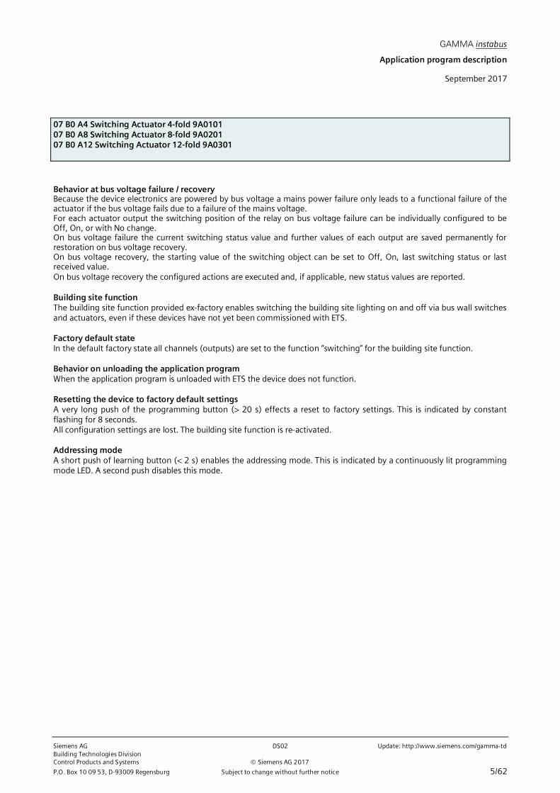
Behavior at bus voltage failure / recoveryBecause the device electronics are powered by bus voltage a mains power failure only leads to a functional failure of theactuator if the bus voltage fails due to a failure of the mains voltage.For each actuator output the switching position of the relay on bus voltage failure can be individually configured to beOff, On, or with No change.On bus voltage failure the current switching status value and further values of each output are saved permanently forrestoration on bus voltage recovery.On bus voltage recovery, the starting value of the switching object can be set to Off, On, last switching status or lastreceived value.On bus voltage recovery the configured actions are executed and, if applicable, new status values are reported.
Building site functionThe building site function provided ex-factory enables switching the building site lighting on and off via bus wall switchesand actuators, even if these devices have not yet been commissioned with ETS.
Factory default stateIn the default factory state all channels (outputs) are set to the function “switching” for the building site function.
Behavior on unloading the application programWhen the application program is unloaded with ETS the device does not function.
Resetting the device to factory default settingsA very long push of the programming button (> 20 s) effects a reset to factory settings. This is indicated by constantflashing for 8 seconds.All configuration settings are lost. The building site function is re-activated.
Addressing modeA short push of learning button (< 2 s) enables the addressing mode. This is indicated by a continuously lit programmingmode LED. A second push disables this mode.

GAMMA instabus
Application program description
September 2017
07 B0 A4 Switching Actuator 4-fold 9A010107 B0 A8 Switching Actuator 8-fold 9A020107 B0 A12 Switching Actuator 12-fold 9A0301
Update: http://www.siemens.com/gamma-td DS02 Siemens AGBuilding Technologies Division
Siemens AG 2017 Control Products and Systems
6/62 Subject to change without further notice P.O. Box 10 09 53, D-93009 Regensburg
2. Communication objects
Maximum number of group addresses: 2000Maximum number of assignments: 2000
Note
The number and names of communication objects visible in the ETS menu can vary depending on the parameter settings.
The application program already has been loaded in the factory.
The device is configured and commissioned with Engineering Tool Software (ETS) version ETS v4.2 or higher.With the ETS (Engineering Tool Software) the specific parameters and addresses are assigned appropriately, and down-loaded into the device.
The following list shows all objects of the device. Which objects are visible and linkable to group addresses is defined viathe functions assigned to the inputs.The objects and associated parameter settings are described with the functions.
No. Object name Function Number of bits Flags
1 Status device function ok / defect 1 Bit CRT2 Send status values request 1 Bit CW3 A Switching ON / OFF 1 Bit CW4 A Control value Value 1 Byte (Percent 0 … 100%) (DPT5.001)
1 Byte (Count pulses 0 … 255) (DPT5.010)2 Byte (Temperature °C) (DPT 9.001)2 Byte (Illuminance lx) (DPT 9.004)2 Byte (Current mA) (DPT 9.021)4 Byte (Power W) (DPT14.056)2 Byte (Power kW) (DPT 9.024)
CW
5 A Status switching ON / OFF 1 Bit CRT6 A Logic operation 1 ON / OFF 1 Bit CW7 A Logic operation 2 ON / OFF 1 Bit CW8 A Central switching ON / OFF 1 Bit CW9 A 8-bit scene recall / store 1 Byte CW10 A Night mode ON / OFF 1 Bit CW11 A Night mode timer ON time (seconds) 2 Bytes CRW12 A Day mode timer ON time (seconds) 2 Bytes CRW13 A Forced control ON / OFF 2 Bit CW14 A Pre-warning expiration of timer period ON / OFF 1 Bit CRT15 A Lock timer ON / OFF 1 Bit CW16 A Override 1, Manual ON ON / OFF 1 Bit CW17 A Override 1, Manual ON, Control value Control value 1 Byte (Percent 0 … 100%) (DPT5.001)
1 Byte (Count pulses 0 … 255) (DPT5.010)2 Byte (Temperature °C) (DPT 9.001)2 Byte (Illuminance lx) (DPT 9.004)2 Byte (Current mA) (DPT 9.021)4 Byte (Power W) (DPT14.056)2 Byte (Power kW) (DPT 9.024)
CW
18 A Override 1, Manual ON, Status ON / OFF 1 Bit CRT19 A Override 2, Permanent-OFF ON / OFF 1 Bit CW20 A Override 2, Permanent-OFF, Control value Value 1 Byte (Percent 0 … 100%) (DPT5.001)
1 Byte (Count pulses 0 … 255) (DPT5.010)2 Byte (Temperature °C) (DPT 9.001)2 Byte (Illuminance lx) (DPT 9.004)2 Byte (Current mA) (DPT 9.021)4 Byte (Power W) (DPT14.056)2 Byte (Power kW) (DPT 9.024)
CW
21 A Override 2,Permanent-OFF, Status ON / OFF 1 Bit CRT22 A Override 3, Lock ON / OFF 1 Bit CW23 A Override 3,Lock, Control value Value 1 Byte (Percent 0 … 100%) (DPT5.001)
1 Byte (Count pulses 0 … 255) (DPT5.010)2 Byte (Temperature °C) (DPT 9.001)2 Byte (Illuminance lx) (DPT 9.004)2 Byte (Current mA) (DPT 9.021)4 Byte (Power W) (DPT14.056)2 Byte (Power kW) (DPT 9.024)
CW

GAMMA instabus
Application program description
September 2017
07 B0 A4 Switching Actuator 4-fold 9A010107 B0 A8 Switching Actuator 8-fold 9A020107 B0 A12 Switching Actuator 12-fold 9A0301
Siemens AG DS02 Update: http://www.siemens.com/gamma-tdBuilding Technologies DivisionControl Products and Systems Siemens AG 2017
P.O. Box 10 09 53, D-93009 Regensburg Subject to change without further notice 7/62
No. Object name Function Number of bits Flags
24 A Override 3, Lock, Status ON / OFF 1 Bit CRT25 A Override 4, Central control ON / OFF 1 Bit CW26 A Override 4,Central control, Control value Value 1 Byte (Percent 0 … 100%) (DPT5.001)
1 Byte (Count pulses 0 … 255) (DPT5.010)2 Byte (Temperature °C) (DPT 9.001)2 Byte (Illuminance lx) (DPT 9.004)2 Byte (Current mA) (DPT 9.021)4 Byte (Power W) (DPT14.056)2 Byte (Power kW) (DPT 9.024)
CW
27 A Override 4, Central control, Status ON / OFF 1 Bit CRT28 A Override 5, User-defined Control ON / OFF 1 Bit CW29 A Override 5, User-defined Control, Control value Value 1 Byte (Percent 0 … 100%) (DPT5.001)
1 Byte (Count pulses 0 … 255) (DPT5.010)2 Byte (Temperature °C) (DPT 9.001)2 Byte (Illuminance lx) (DPT 9.004)2 Byte (Current mA) (DPT 9.021)4 Byte (Power W) (DPT14.056)2 Byte (Power kW) (DPT 9.024)
CW
30 A Override 5, User-defined Control, Status ON / OFF 1 Bit CRT31 A Override 6,User-defined Control ON / OFF 1 Bit CW32 A Override 6,User-defined Control, Control value Value 1 Byte (Percent 0 … 100%) (DPT5.001)
1 Byte (Count pulses 0 … 255) (DPT5.010)2 Byte (Temperature °C) (DPT 9.001)2 Byte (Illuminance lx) (DPT 9.004)2 Byte (Current mA) (DPT 9.021)4 Byte (Power W) (DPT14.056)2 Byte (Power kW) (DPT 9.024)
CW
33 A Override 6,User-defined Control, Status ON / OFF 1 Bit CRT34 A Number of switching cycles Value 4 Byte CRT35 A Number of switching cycles Set Value 4 Byte CW36 A Threshold for switching cycles Set Value 4 Byte CRW37 A Exceedance of threshold for switching cycles ON / OFF 1 Bit CRT38 A Operating hours Value 4 Byte CRT39 A Operating hours Value (in seconds) 4 Byte CRT40 A Operating hours Set Value 4 Byte CW41 A Threshold for switching cycles Set Value 4 Byte CRW42 A Exceedance of threshold for switching cycles ON / OFF 1 Bit CRT

GAMMA instabus
Application program description
September 2017
07 B0 A4 Switching Actuator 4-fold 9A010107 B0 A8 Switching Actuator 8-fold 9A020107 B0 A12 Switching Actuator 12-fold 9A0301
Update: http://www.siemens.com/gamma-td DS02 Siemens AGBuilding Technologies Division
Siemens AG 2017 Control Products and Systems
8/62 Subject to change without further notice P.O. Box 10 09 53, D-93009 Regensburg
3. Device Settings
In this parameter window those settings are determined which span across channels and functions. Additionally, in thisparameter window the function of the respective channels is selected.The function for channel A-D, A-H or A-L is configured in the same manner and thus is only described once for channel A.
Objects
Obj Object name Function Type Flag
1 Status device function ok / defect 1 Bit CRT
The value “0” is regularly sent via this object when the device is in operation. If the device does not send cyclicallyanymore, then this indicates a device failure. Only in case of a malfunction, which can be deteted by the device itself,will it send the value “1”.Via a parameter the status of the device function can be sent as an inverted value. Then on normal operation the devicewill cyclically send the value “1”. Only in case of a malfunction, which can be deteted by the device itself, will it send thevalue “0”.A supervisory system may monitor the cyclical sending and initiate e.g. a warning or alarm message on missing thestatus message.Note:A malfunction may be a failure of a part of the hardware, which is required for the proper function of the device orindividual channels, but does not lead to failure of the device communication, as is the case on bus voltage failure. Amalfunction may be present, if e.g. necessary calibrations cannot be performed and the device cannot function properlyor not at all.
2 Send status values Request 1 Bit CW
When a telegram with any value (“1” or “0”) is received via this object then sending of the current status values for allthose status objects is triggered, for which “sending on request” for the status object is enabled.
GAMMA instabus
Application program description
September 2017
07 B0 A4 Switching Actuator 4-fold 9A010107 B0 A8 Switching Actuator 8-fold 9A020107 B0 A12 Switching Actuator 12-fold 9A0301
Siemens AG DS02 Update: http://www.siemens.com/gamma-tdBuilding Technologies DivisionControl Products and Systems Siemens AG 2017
P.O. Box 10 09 53, D-93009 Regensburg Subject to change without further notice 9/62
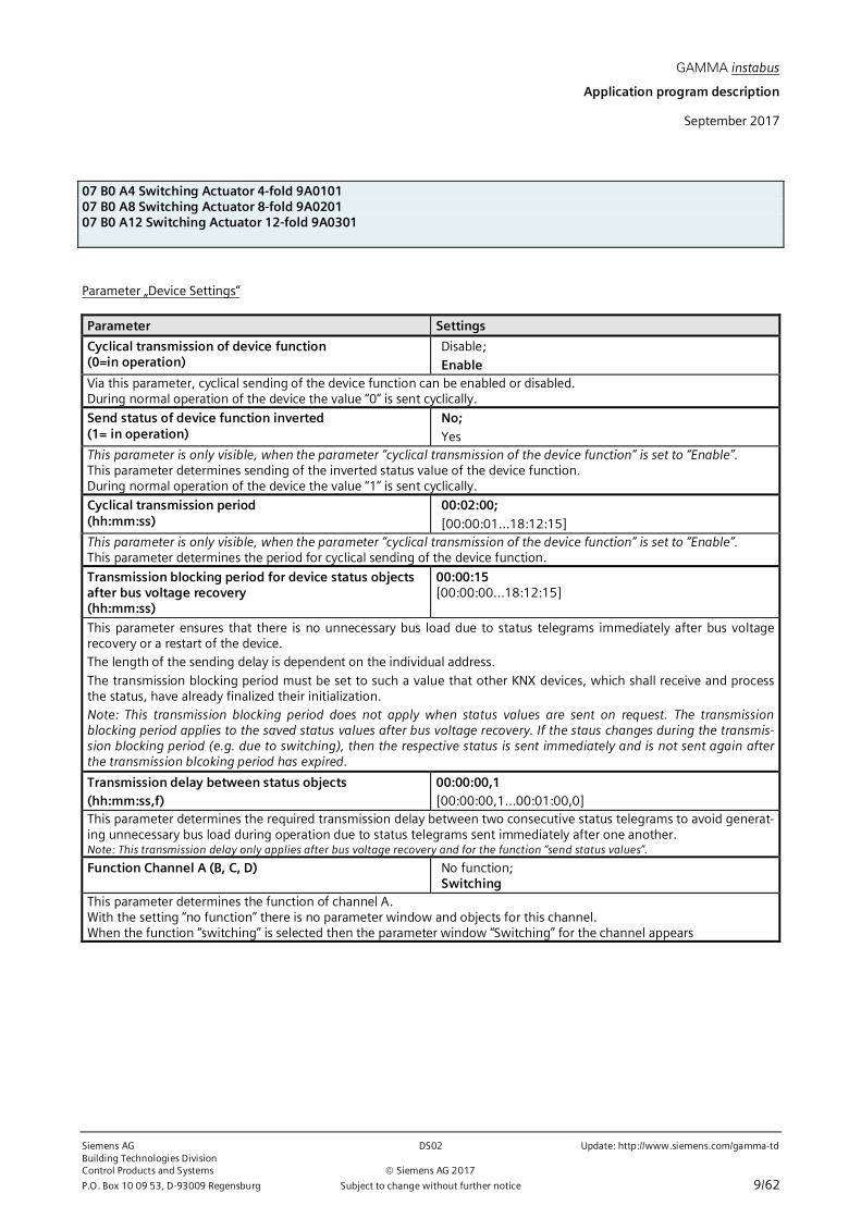
Parameter „Device Settings“
Parameter Settings
Cyclical transmission of device function(0=in operation)
Disable;
EnableVia this parameter, cyclical sending of the device function can be enabled or disabled.During normal operation of the device the value “0” is sent cyclically.
Send status of device function inverted(1= in operation)
No;Yes
This parameter is only visible, when the parameter “cyclical transmission of the device function” is set to “Enable”.This parameter determines sending of the inverted status value of the device function.During normal operation of the device the value “1” is sent cyclically.
Cyclical transmission period(hh:mm:ss)
00:02:00;[00:00:01…18:12:15]
This parameter is only visible, when the parameter “cyclical transmission of the device function” is set to “Enable”.This parameter determines the period for cyclical sending of the device function.
Transmission blocking period for device status objectsafter bus voltage recovery(hh:mm:ss)
00:00:15[00:00:00…18:12:15]
This parameter ensures that there is no unnecessary bus load due to status telegrams immediately after bus voltagerecovery or a restart of the device.The length of the sending delay is dependent on the individual address.
The transmission blocking period must be set to such a value that other KNX devices, which shall receive and processthe status, have already finalized their initialization.Note: This transmission blocking period does not apply when status values are sent on request. The transmissionblocking period applies to the saved status values after bus voltage recovery. If the staus changes during the transmis-sion blocking period (e.g. due to switching), then the respective status is sent immediately and is not sent again afterthe transmission blcoking period has expired.
Transmission delay between status objects(hh:mm:ss,f)
00:00:00,1[00:00:00,1…00:01:00,0]
This parameter determines the required transmission delay between two consecutive status telegrams to avoid generat-ing unnecessary bus load during operation due to status telegrams sent immediately after one another.Note: This transmission delay only applies after bus voltage recovery and for the function “send status values”.
Function Channel A (B, C, D) No function;Switching
This parameter determines the function of channel A.With the setting “no function” there is no parameter window and objects for this channel.When the function “switching” is selected then the parameter window “Switching” for the channel appears

GAMMA instabus
Application program description
September 2017
07 B0 A4 Switching Actuator 4-fold 9A010107 B0 A8 Switching Actuator 8-fold 9A020107 B0 A12 Switching Actuator 12-fold 9A0301
Update: http://www.siemens.com/gamma-td DS02 Siemens AGBuilding Technologies Division
Siemens AG 2017 Control Products and Systems
10/62 Subject to change without further notice P.O. Box 10 09 53, D-93009 Regensburg
4. Channel settings (Switching)
The objects and parameters are configured the same for all channels. Hence, this is described only once for channel A.Each actuator output can be configured with the following partial functions:
∂ Control Value Input∂ Switching (Normal mode)∂ Switching (Timer mode)∂ Flashing∂ Logic operations∂ Central switching∂ 8-bit scene control∂ Night mode∂ Override
o Manual overrideo Permanent OFFo Locko Central override controlo User-defined Controlo Forced Control
∂ Status annunciation∂ Number of switching cycles with or without threshold monitoring∂ Number of operating hours with or without threshold monitoring
Except for the parameter windows for the operation mode dependent settings and the logical gates, all other parameterwindows appear only after specific parameter selection in the parameter window “Functions, objects”.The parameter window “Functions, objects” is always described before the specific parameter window.
The following sections describe the functions, which can be configured for the channel, including the associated objectsand parameter settings.

GAMMA instabus
Application program description
September 2017
07 B0 A4 Switching Actuator 4-fold 9A010107 B0 A8 Switching Actuator 8-fold 9A020107 B0 A12 Switching Actuator 12-fold 9A0301
Siemens AG DS02 Update: http://www.siemens.com/gamma-tdBuilding Technologies DivisionControl Products and Systems Siemens AG 2017
P.O. Box 10 09 53, D-93009 Regensburg Subject to change without further notice 11/62
Note
The number and names of the parameter windows in the ETS menus may vary as they are controlled via parametersettings. Another parameter window may appear if due to dynamically added parameters the space in the first parameterwindow is exhausted.
Functions, Objects
In this section only those parameters are described that do not activate further parameter windows or have furtherparameters appear in a following parameter window.Parameters, which activate a further parameter window or have further parameters appear in a following parameterwindow, are described in the respective section.

GAMMA instabus
Application program description
September 2017
07 B0 A4 Switching Actuator 4-fold 9A010107 B0 A8 Switching Actuator 8-fold 9A020107 B0 A12 Switching Actuator 12-fold 9A0301
Update: http://www.siemens.com/gamma-td DS02 Siemens AGBuilding Technologies Division
Siemens AG 2017 Control Products and Systems
12/62 Subject to change without further notice P.O. Box 10 09 53, D-93009 Regensburg
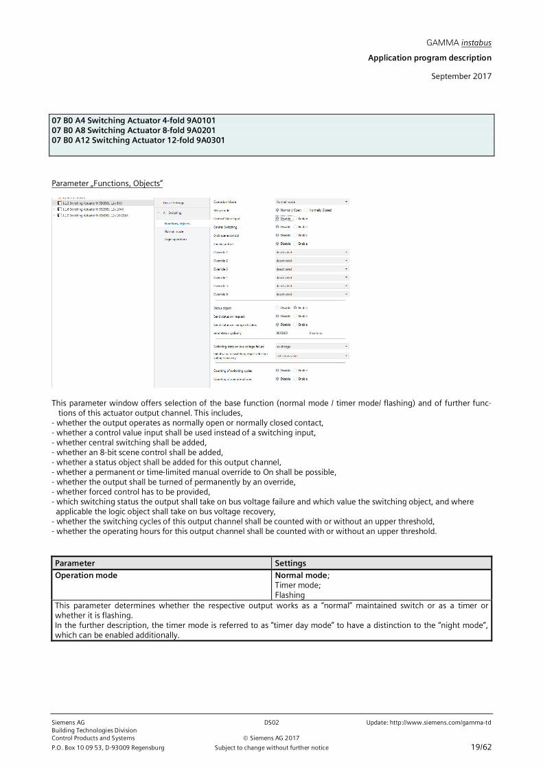
Parameter „Functions, Objects“
This parameter window offers selection of the base function (normal mode / timer mode/ flashing) and of further func-tions of this actuator output channel. This includes,- whether the output operates as normally open or normally closed contact,- which switching status the output shall take on bus voltage failure and which value the switching object, and where applicable the logic object shall take on bus voltage recovery,- whether a control value input shall be used instead of a switching input,- whether central switching shall be added,- whether an 8-bit scene control shall be added,- whether a status object shall be added for this output channel,- whether a permanent or time-limited manual override to On shall be possible,- whether the output shall be turned of permanently by an override,- whether forced control has to be provided,- whether the switching cycles of this output channel shall be counted with or without an upper threshold,- whether the operating hours for this output channel shall be counted with or without an upper threshold.
Parameter Settings
Relay mode Normally open contact;Normally closed contact
This parameter determines the behavior of the output (relay contact). With the "normally closed contact" setting,"Switch off" always means closing the contact and "Switch on" always means opening the contact."normally open contact": Off telegram = contact open,
On telegram = contact closed."normally closed contact": Off telegram = contact closed,
On telegram = contact open.

GAMMA instabus
Application program description
September 2017
07 B0 A4 Switching Actuator 4-fold 9A010107 B0 A8 Switching Actuator 8-fold 9A020107 B0 A12 Switching Actuator 12-fold 9A0301
Siemens AG DS02 Update: http://www.siemens.com/gamma-tdBuilding Technologies DivisionControl Products and Systems Siemens AG 2017
P.O. Box 10 09 53, D-93009 Regensburg Subject to change without further notice 13/62
Parameter Settings
Switching state on bus voltage failure Off;On;no change
This parameter determines the desired switching state of the output on bus voltage failure.On bus voltage failure the current switching state (if need be after execution of the configured switching command) issaved in non-volatile memory.
Initial value of switching object after bus voltagerecovery
Off;On;Last status value;Last value received
This parameter determines the starting value of the switching object after bus voltage recovery.Last status value: The initial value is set to the status value of the channel on bus voltage failure.Last value received: The initial value is set to the value of the switching object on bus voltage failure.Note: Dependent on the configuration the switching state of the output may change against the switching state on busvoltage failure.
Further parameter settings are described in these sections:⇔ Control Value Input⇔ Switching (Normal mode)⇔ Switching (Timer mode)⇔ Flashing⇔ Logic operation⇔ Central switching⇔ 8-bit scene control⇔ Night mode⇔ Manual override (ON)⇔ Permanent OFF⇔ Lock⇔ Central override⇔ User-defined Control⇔ Forced control⇔ Status annunciation⇔ Counting of switching cycles⇔ Counting of operating hours

GAMMA instabus
Application program description
September 2017
07 B0 A4 Switching Actuator 4-fold 9A010107 B0 A8 Switching Actuator 8-fold 9A020107 B0 A12 Switching Actuator 12-fold 9A0301
Update: http://www.siemens.com/gamma-td DS02 Siemens AGBuilding Technologies Division
Siemens AG 2017 Control Products and Systems
14/62 Subject to change without further notice P.O. Box 10 09 53, D-93009 Regensburg
Control Value Input
Switching
Logic operation 1
01
0 1
Logic operation 1
Control value input
Send status value
Control value
Function Control Value Input
For each channel, there is a control value input as an alternative to the switching input. Via this control value input analogvalues can be transposed into On respectively Off commands. Percentage values, integers (0…255), temperature in °C(DPT 9.001), illuminance in lux (DPT 9.004), current in mA (DPT 9.021) and power in W (DPT 14.056) or kW (DPT 9.024)can be used.
Also for the override functions instead of the switching input a control value input can be used with the correspondingobject. The available parameter settings are the same. Hence, the parameter descriptions are the same.
Objects
Obj Object name Function Type Flag
4 A Control value Value 1 Byte (Percent 0 … 100%) (DPT5.001)1 Byte (Count pulses 0 … 255) (DPT5.010)2 Byte (Temperature °C) (DPT 9.001)2 Byte (Illuminance lx) (DPT 9.004)2 Byte (Current mA) (DPT 9.021)4 Byte (Power W) (DPT14.056)2 Byte (Power kW) (DPT 9.024)
CW
The control value telegrams for the channel are received via this object in normal or timer operation mode.A received control value is transformed into a switching signal via a threshold evaluation.
Format and data point type of the object are determined via the parameter “Data Type”.
16 A Override 1, Manual ON, Controlvalue
Value 1 Byte (Percent 0 … 100%) (DPT5.001)1 Byte (Count pulses 0 … 255) (DPT5.010)2 Byte (Temperature °C) (DPT 9.001)2 Byte (Illuminance lx) (DPT 9.004)2 Byte (Current mA) (DPT 9.021)4 Byte (Power W) (DPT14.056)2 Byte (Power kW) (DPT 9.024)
CW
The control value telegrams for the override 1 (here: Manual ON) are received via this object.A received control value is transformed into a switching signal via a threshold evaluation.Format and data point type of the object are determined via the parameter “Data Type”.

GAMMA instabus
Application program description
September 2017
07 B0 A4 Switching Actuator 4-fold 9A010107 B0 A8 Switching Actuator 8-fold 9A020107 B0 A12 Switching Actuator 12-fold 9A0301
Siemens AG DS02 Update: http://www.siemens.com/gamma-tdBuilding Technologies DivisionControl Products and Systems Siemens AG 2017
P.O. Box 10 09 53, D-93009 Regensburg Subject to change without further notice 15/62
Obj Object name Function Type Flag
19 A Override 2,Permanent OFF,Control value
Value 1 Byte (Percent 0 … 100%) (DPT5.001)1 Byte (Count pulses 0 … 255) (DPT5.010)2 Byte (Temperature °C) (DPT 9.001)2 Byte (Illuminance lx) (DPT 9.004)2 Byte (Current mA) (DPT 9.021)4 Byte (Power W) (DPT14.056)2 Byte (Power kW) (DPT 9.024)
CW
The control value telegrams for the override 2 (here: Permanent OFF) are received via this object.A received control value is transformed into a switching signal via a threshold evaluation.Format and data point type of the object are determined via the parameter “Data Type”.
22 A Override 3, Lock, Control value Value 1 Byte (Percent 0 … 100%) (DPT5.001)1 Byte (Count pulses 0 … 255) (DPT5.010)2 Byte (Temperature °C) (DPT 9.001)2 Byte (Illuminance lx) (DPT 9.004)2 Byte (Current mA) (DPT 9.021)4 Byte (Power W) (DPT14.056)2 Byte (Power kW) (DPT 9.024)
CW
The control value telegrams for the override 3 (here: Lock) are received via this object.A received control value is transformed into a switching signal via a threshold evaluation.Format and data point type of the object are determined via the parameter “Data Type”.
25 A Override 4, Central, Control value Value 1 Byte (Percent 0 … 100%) (DPT5.001)1 Byte (Count pulses 0 … 255) (DPT5.010)2 Byte (Temperature °C) (DPT 9.001)2 Byte (Illuminance lx) (DPT 9.004)2 Byte (Current mA) (DPT 9.021)4 Byte (Power W) (DPT14.056)2 Byte (Power kW) (DPT 9.024)
CW
The control value telegrams for the override 4 (here: Central) are received via this object.
A received control value is transformed into a switching signal via a threshold evaluation.Format and data point type of the object are determined via the parameter “Data Type”.
28 A Override 5, User-defined Control,Control value
Value 1 Byte (Percent 0 … 100%) (DPT5.001)1 Byte (Count pulses 0 … 255) (DPT5.010)2 Byte (Temperature °C) (DPT 9.001)2 Byte (Illuminance lx) (DPT 9.004)2 Byte (Current mA) (DPT 9.021)4 Byte (Power W) (DPT14.056)2 Byte (Power kW) (DPT 9.024)
CW
The control value telegrams for the override 5 (here: User-defined) are received via this object.A received control value is transformed into a switching signal via a threshold evaluation.
Format and data point type of the object are determined via the parameter “Data Type”.

GAMMA instabus
Application program description
September 2017
07 B0 A4 Switching Actuator 4-fold 9A010107 B0 A8 Switching Actuator 8-fold 9A020107 B0 A12 Switching Actuator 12-fold 9A0301
Update: http://www.siemens.com/gamma-td DS02 Siemens AGBuilding Technologies Division
Siemens AG 2017 Control Products and Systems
16/62 Subject to change without further notice P.O. Box 10 09 53, D-93009 Regensburg
Obj Object name Function Type Flag
32 A Override 6, User-defined Control,Control value
Value 1 Byte (Percent 0 … 100%) (DPT5.001)1 Byte (Count pulses 0 … 255) (DPT5.010)2 Byte (Temperature °C) (DPT 9.001)2 Byte (Illuminance lx) (DPT 9.004)2 Byte (Current mA) (DPT 9.021)4 Byte (Power W) (DPT14.056)2 Byte (Power kW) (DPT 9.024)
CW
The control value telegrams for the override 6 (here: User-defined) are received via this object.A received control value is transformed into a switching signal via a threshold evaluation.Format and data point type of the object are determined via the parameter “Data Type”.
Parameter „Functions, Objects“
Parameter Settings
Control Value Input Disable;Enable
This parameter determines if the object “Control Value” for the channel and the associated parameters are visible.The switching input is invisible as long as the control value input is visible.
GAMMA instabus
Application program description
September 2017
07 B0 A4 Switching Actuator 4-fold 9A010107 B0 A8 Switching Actuator 8-fold 9A020107 B0 A12 Switching Actuator 12-fold 9A0301
Siemens AG DS02 Update: http://www.siemens.com/gamma-tdBuilding Technologies DivisionControl Products and Systems Siemens AG 2017
P.O. Box 10 09 53, D-93009 Regensburg Subject to change without further notice 17/62
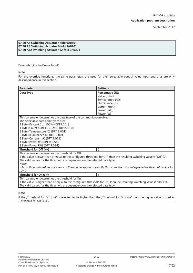
Parameter „Control Value Input“
Note
For the override functions, the same parameters are used for their selectable control value input and thus are onlydescribed once in this section.
Parameter Settings
Data Type Percentage (%);Value (8-bit);Temperature (°C);Illuminance (lx);Current (mA);Power (kW);Power (W)
This parameter determines the data type of the communication object.The selectable data point types are:1 Byte (Percent 0 … 100%) (DPT5.001)1 Byte (Count pulses 0 … 255) (DPT5.010)2 Byte (Temperature °C) (DPT 9.001)2 Byte (Illuminance lx) (DPT 9.004)2 Byte (Current mA) (DPT 9.021)4 Byte (Power W) (DPT14.056)2 Byte (Power kW) (DPT 9.024)Threshold for Off (<=) 0This parameter determines the threshold for Off.If the value is lower than or equal to the configured threshold for Off, then the resulting switching value is “Off” (0).The valid values for the threshold are dependent on the selected data type.Note:If both threshold values are identical then on reception of exactly this value then it is interpreted as threshold value for„On“.Threshold for On (>=) 1This parameter determines the threshold for On.If the value is higher than or equal to the configured threshold for On, then the resulting switching value is “On” (1).The valid values for the threshold are dependent on the selected data type.
Note
If the „Threshold for Off (<=)“ is selected to be higher than the „Threshold for On (>=)“ then the higher value is used as„Threshold for On (>=)“.
GAMMA instabus
Application program description
September 2017
07 B0 A4 Switching Actuator 4-fold 9A010107 B0 A8 Switching Actuator 8-fold 9A020107 B0 A12 Switching Actuator 12-fold 9A0301
Update: http://www.siemens.com/gamma-td DS02 Siemens AGBuilding Technologies Division
Siemens AG 2017 Control Products and Systems
18/62 Subject to change without further notice P.O. Box 10 09 53, D-93009 Regensburg
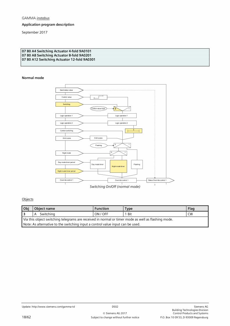
Normal mode
Switching
Logic operation 1
Logic operation 2
Central switching
8-bit scene
Night mode
Day mode timer period
Night mode timer period
01
0 1
Logic operation 1
Logic operation 2
t
8-bit scene
0 1Flashing
0 1
Day mode timer FlashingNight mode timer
Override control 1
Control value input
Override control 1 Status Override control 1
Send status value
Control value
Switching On/Off (normal mode)
Objects
Obj Object name Function Type Flag
3 A Switching ON / OFF 1 Bit CW
Via this object switching telegrams are received in normal or timer mode as well as flashing mode.Note: As alternative to the switching input a control value input can be used.
GAMMA instabus
Application program description
September 2017
07 B0 A4 Switching Actuator 4-fold 9A010107 B0 A8 Switching Actuator 8-fold 9A020107 B0 A12 Switching Actuator 12-fold 9A0301
Siemens AG DS02 Update: http://www.siemens.com/gamma-tdBuilding Technologies DivisionControl Products and Systems Siemens AG 2017
P.O. Box 10 09 53, D-93009 Regensburg Subject to change without further notice 19/62
Parameter „Functions, Objects“
This parameter window offers selection of the base function (normal mode / timer mode/ flashing) and of further func-tions of this actuator output channel. This includes,
- whether the output operates as normally open or normally closed contact,- whether a control value input shall be used instead of a switching input,- whether central switching shall be added,- whether an 8-bit scene control shall be added,- whether a status object shall be added for this output channel,- whether a permanent or time-limited manual override to On shall be possible,- whether the output shall be turned of permanently by an override,- whether forced control has to be provided,- which switching status the output shall take on bus voltage failure and which value the switching object, and where applicable the logic object shall take on bus voltage recovery,- whether the switching cycles of this output channel shall be counted with or without an upper threshold,- whether the operating hours for this output channel shall be counted with or without an upper threshold.
Parameter Settings
Operation mode Normal mode;Timer mode;Flashing
This parameter determines whether the respective output works as a “normal” maintained switch or as a timer orwhether it is flashing.In the further description, the timer mode is referred to as “timer day mode” to have a distinction to the “night mode”,which can be enabled additionally.

GAMMA instabus
Application program description
September 2017
07 B0 A4 Switching Actuator 4-fold 9A010107 B0 A8 Switching Actuator 8-fold 9A020107 B0 A12 Switching Actuator 12-fold 9A0301
Update: http://www.siemens.com/gamma-td DS02 Siemens AGBuilding Technologies Division
Siemens AG 2017 Control Products and Systems
20/62 Subject to change without further notice P.O. Box 10 09 53, D-93009 Regensburg
The parameter ”Operation mode“ is set to “Normal mode“.
The other parameters are covered in the sections⇔ Control Value Input⇔ Central switching⇔ 8-bit scene control⇔ Manual override (ON)⇔ Permanent OFF⇔ Lock⇔ Central override⇔ User-defined Control⇔ Forced control⇔ Status annunciation⇔ Counting of switching cycles⇔ Counting of operating hours
Parameter „Normal mode“
This parameter window is used to set the switching behavior in "Normal mode" of the corresponding actuator outputchannel.The parameter window for the output channel is used to set- whether an “on” delay shall be executed and how long the period for the on delay is,- whether an “off” delay shall be executed and how long the period for the off delay is,- whether night mode with a time- controlled “On” period is desired, and how long the “On” period is,- whether in night mode a warning before switching off shall be executed.
Parameter Settings
ON delay[hh:mm:ss]
00:00:00[00:00:00...23:59:59]
This parameter sets the wanted on-delay time. The default value 00:00:00 means that ON commands are executedimmediately. A set on-delay acts on the "Switching" object and on an object for a logic operation allocated to the outputas well.
OFF delay[hh:mm:ss]
00:00:00[00:00:00...23:59:59]
This parameter sets the wanted off-delay time. The default value 00:00:00 means that OFF commands are executedimmediately. A set off-delay acts on the "Switching" object and on an object for a logic operation allocated to the outputas well.
The other parameters are covered in the sections⇔ Night mode.
GAMMA instabus
Application program description
September 2017
07 B0 A4 Switching Actuator 4-fold 9A010107 B0 A8 Switching Actuator 8-fold 9A020107 B0 A12 Switching Actuator 12-fold 9A0301
Siemens AG DS02 Update: http://www.siemens.com/gamma-tdBuilding Technologies DivisionControl Products and Systems Siemens AG 2017
P.O. Box 10 09 53, D-93009 Regensburg Subject to change without further notice 21/62
Timer mode
Switching
Logic operation 1
Logic operation 2
Central switching
8-bit scene
Night mode
Day mode timer period
Night mode timer period
01
0 1
Logic operation 1
Logic operation 2
t
8-bit scene
0 1Flashing
0 1
Day mode timer FlashingNight mode timer
Override control 1
Control value input
Override control 1 Status Override control 1
Send status value
Control value
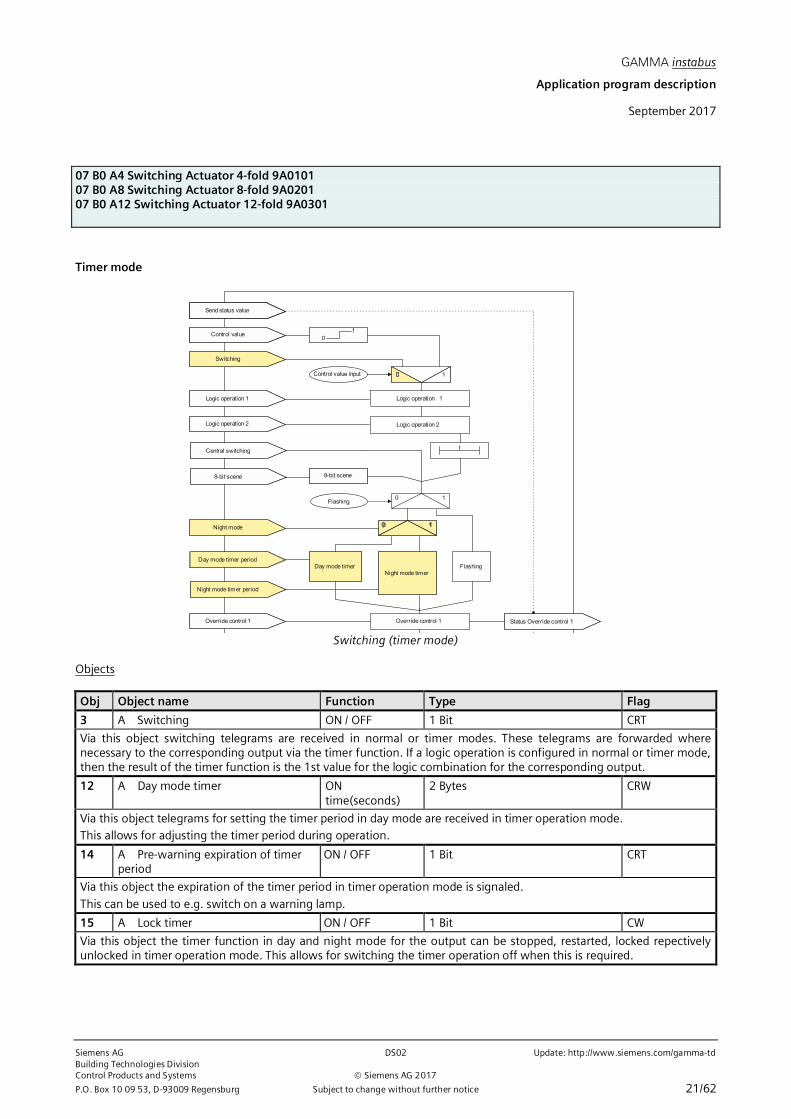
Switching (timer mode)
Objects
Obj Object name Function Type Flag
3 A Switching ON / OFF 1 Bit CRT
Via this object switching telegrams are received in normal or timer modes. These telegrams are forwarded wherenecessary to the corresponding output via the timer function. If a logic operation is configured in normal or timer mode,then the result of the timer function is the 1st value for the logic combination for the corresponding output.
12 A Day mode timer ONtime(seconds)
2 Bytes CRW
Via this object telegrams for setting the timer period in day mode are received in timer operation mode.This allows for adjusting the timer period during operation.
14 A Pre-warning expiration of timerperiod
ON / OFF 1 Bit CRT
Via this object the expiration of the timer period in timer operation mode is signaled.
This can be used to e.g. switch on a warning lamp.
15 A Lock timer ON / OFF 1 Bit CW
Via this object the timer function in day and night mode for the output can be stopped, restarted, locked repectivelyunlocked in timer operation mode. This allows for switching the timer operation off when this is required.

GAMMA instabus
Application program description
September 2017
07 B0 A4 Switching Actuator 4-fold 9A010107 B0 A8 Switching Actuator 8-fold 9A020107 B0 A12 Switching Actuator 12-fold 9A0301
Update: http://www.siemens.com/gamma-td DS02 Siemens AGBuilding Technologies Division
Siemens AG 2017 Control Products and Systems
22/62 Subject to change without further notice P.O. Box 10 09 53, D-93009 Regensburg
Parameter „Functions, Objects“
This parameter window offers selection of the base function (normal mode / timer mode/ flashing) and of further func-tions of this actuator output channel. This includes,
- whether the output operates as normally open or normally closed contact,- whether a control value input shall be used instead of a switching input,- whether central switching shall be added,- whether an 8-bit scene control shall be added,- whether a status object shall be added for this output channel,- whether a permanent or time-limited manual override to On shall be possible,- whether the output shall be turned of permanently by an override,- whether forced control has to be provided,- which switching status the output shall take on bus voltage failure and which value the switching object, and where applicable the logic object shall take on bus voltage recovery,- whether the switching cycles of this output channel shall be counted with or without an upper threshold,- whether the operating hours for this output channel shall be counted with or without an upper threshold.
Parameter Settings
Operation mode Normal mode;Timer mode;Flashing
This parameter determines whether the respective output works as a “normal” maintained switch or as a timer orwhether it is flashing.In the further description, the timer mode is referred to as “timer day mode” to have a distinction to the “night mode”,which can be enabled additionally.
The parameter ”Operation mode“ is set to “Timer mode“.
The other parameters are covered in the sections⇔ Control Value Input

GAMMA instabus
Application program description
September 2017
07 B0 A4 Switching Actuator 4-fold 9A010107 B0 A8 Switching Actuator 8-fold 9A020107 B0 A12 Switching Actuator 12-fold 9A0301
Siemens AG DS02 Update: http://www.siemens.com/gamma-tdBuilding Technologies DivisionControl Products and Systems Siemens AG 2017
P.O. Box 10 09 53, D-93009 Regensburg Subject to change without further notice 23/62
⇔ Central switching⇔ 8-bit scene control⇔ Manual override (ON)⇔ Permanent OFF⇔ Lock⇔ Central override⇔ User-defined Control⇔ Forced control⇔ Status annunciation⇔ Counting of switching cycles⇔ Counting of operating hours
Parameter „Timer mode“
This parameter window is used to set the switching behavior in "Timer mode" of the corresponding actuator outputchannel.The parameter window for the output channel is used to set- how long the timer period shall be,- whether the timer may be re-triggered,- whether a warning before switching off shall be executed,- whether the On period in day mode timer operation shall be changeable at run-time, whether night mode with a time- controlled “On” period is desired, and how long the “On” period is,- whether in night mode a warning before switching off shall be executed.
Parameter Settings
ON time in day mode[hh:mm:ss]
00:15:00[00:00:00 … 23:59:59]
This parameter sets the desired on-time for the output in timer day mode.
Retriggering possible 1[0…5]
This parameter determines whether the On period is restarted and thus the On time is to be extended when a new Ontelegram is received during an On period.If the parameter is set to “0” then an extension is not possible during the On period.Additionally, it ispossible to determine how long the On period can be extended at maximum by receiving severalswitching telegrams. Thus the maximum settable period is:1: up to max. 1x ON time2: up to max. 2x ON time3: up to max. 3x ON time4: up to max. 4x ON time5: up to max. 5x ON time

GAMMA instabus
Application program description
September 2017
07 B0 A4 Switching Actuator 4-fold 9A010107 B0 A8 Switching Actuator 8-fold 9A020107 B0 A12 Switching Actuator 12-fold 9A0301
Update: http://www.siemens.com/gamma-td DS02 Siemens AGBuilding Technologies Division
Siemens AG 2017 Control Products and Systems
24/62 Subject to change without further notice P.O. Box 10 09 53, D-93009 Regensburg
Parameter Settings
Warning before switching Off No;via briefly switching On – Off;
via communication object;via briefly switching On – Off and via communicationobject;
This parameter determines whether at the end of the On time the output immediately shall be turned off permanentlyor if a warning shall happen before the output switching off.„No“:
The output is immediately switched Off without warning.
With the following parameter settings the output is not immediately switched Off permanently.If the output is used for lighting control then the user is warned and has ample time to extend the On period of thelighting or if need be turn it on again.„via briefly switching On – Off“:
The output is switched off for the configurable warning signal period (default setting: 1s) and then switched on againfor a configurable time (difference of parameter „warning period“ – parameter „warning signal period“).Note:The „warning signal period“ shall not be longer than the „warning period“ because otherwise no warning willoccur!If within the warning period the output is switched on again via e.g. the object „switching“ then the timer On periodstarts again. Otherwise, the output is switched off.
„via communciation object“:Via this selection the communication object „Pre-warning expiration of timer period” appears, which can be used tosend a pre-warning onto the bus e.g. to switch on a warning lamp.The expiration of the On period of the timer is signaled via the communication object. At the same time the warningperiod starts with a period defined by the parameter “warning period”. The output is not briefly switched on/off.If within the warning period the output is switched on again via e.g. the object „switching“ then the timer On periodstarts again. Otherwise, the output is switched off.
via briefly switching On – Off and via communication object:Via this selection the communication object „Pre-warning expiration of timer period” appears, which can be used tosend a pre-warning onto the bus e.g. to switch on a warning lamp.The expiration of the On period of the timer is signaled via the communication object. The output is switched off forthe configurable warning signal period (default setting: 1s) and then switched on again for a configurable time(difference of parameter „warning period“ – parameter „warning signal period“).Note:The „warning signal period“ shall not be longer than the „warning period“ because otherwise no warning willoccur!If within the warning period the output is switched on again via e.g. the object „switching“ then the timer On periodstarts again. Otherwise, the output is switched off.
Warning period[hh:mm:ss]
00:00:30[00:00:01…18:12:15]
This parameter is only visible if the parameter „Warning before switching Off“is not set to „No“.This parameter determines the warning period during which the output stays switched On after the timer expired.Note:The „warning signal period“ shall not be longer than the „warning period“ because otherwise no warning willoccur!
Warning signal period[hh:mm:ss]
00:00:01[00:00:01…18:12:15]
This parameter is only visible if the parameter „warning before switching Off“ is set to „via briefly switching On – Off“ or„via briefly switching On – Off and via communication object“.This parameter determines that, after the On period has expired, the output is not immediately switched offpermanently but only switched off for a warning signal period (default setting: 1 second) and then switched on againfor a configurable time (difference of parameter „warning period“ – parameter „warning signal period“). After this

GAMMA instabus
Application program description
September 2017
07 B0 A4 Switching Actuator 4-fold 9A010107 B0 A8 Switching Actuator 8-fold 9A020107 B0 A12 Switching Actuator 12-fold 9A0301
Siemens AG DS02 Update: http://www.siemens.com/gamma-tdBuilding Technologies DivisionControl Products and Systems Siemens AG 2017
P.O. Box 10 09 53, D-93009 Regensburg Subject to change without further notice 25/62
Parameter Settings
warning period has expired the output is switched off permanently. If the output is used for lighting control then theuser is warned and has ample time to extend the On period of the lighting or, if need be, turn it on again.Note:The „warning signal period“ shall not be longer than the „warning period“ because otherwise no warning willoccur!
Change ON time during day mode via object Disable;Enable
This parameter determines if the object “Day mode timer” is available.
Blocking characteristics for time mode Deactivate timer;Reset timer;Pause timer;no blocking
This parameter determines the blocking behavior in timer operation mode.„no blocking“:
Blocking of the timer is not possible.If one of the following parameter settings is selected then a blocking object for the timer appears.„Pause timer“:
Triggered timer functions are halted and continue running after release of the blocking object at the time when thewere halted.
„Reset timer“:Triggered timer functions are halted. After release of the blocking object the timer is reset and restarted again.
„Deactivate timer“:Triggered timer functions are stopped. After release of the blocking object the timer is neither continued nor restart-ed.
The other parameters are covered in the sections⇔ Night mode.

GAMMA instabus
Application program description
September 2017
07 B0 A4 Switching Actuator 4-fold 9A010107 B0 A8 Switching Actuator 8-fold 9A020107 B0 A12 Switching Actuator 12-fold 9A0301
Update: http://www.siemens.com/gamma-td DS02 Siemens AGBuilding Technologies Division
Siemens AG 2017 Control Products and Systems
26/62 Subject to change without further notice P.O. Box 10 09 53, D-93009 Regensburg
Flashing
Switching
Logic operation 1
Logic operation 2
Central switching
8-bit scene
Night mode
Day mode timer period
Night mode timer period
01
0 1
Logic operation 1
Logic operation 2
t
8-bit scene
0 1Flashing
0 1
Day mode timer FlashingNight mode timer
Override control 1
Control value input
Override control 1 Status Override control 1
Send status value
Control value
Funktion Schalten Ein/Aus
Objects
Obj Object name Function Type Flag
3 A Switching ON / OFF 1 Bit CRT
Via this object switching telegrams are received.

GAMMA instabus
Application program description
September 2017
07 B0 A4 Switching Actuator 4-fold 9A010107 B0 A8 Switching Actuator 8-fold 9A020107 B0 A12 Switching Actuator 12-fold 9A0301
Siemens AG DS02 Update: http://www.siemens.com/gamma-tdBuilding Technologies DivisionControl Products and Systems Siemens AG 2017
P.O. Box 10 09 53, D-93009 Regensburg Subject to change without further notice 27/62
Parameter „Functions, Objects“
This parameter window offers selection of the base function (normal mode / timer mode/ flashing) and of further func-tions of this actuator output channel. This includes,
- whether the output operates as normally open or normally closed contact,- whether a control value input shall be used instead of a switching input,- whether central switching shall be added,- whether an 8-bit scene control shall be added,- whether a status object shall be added for this output channel,- whether a permanent or time-limited manual override to On shall be possible,- whether forced control has to be provided,- which switching status the output shall take on bus voltage failure and which value the switching object, and where applicable the logic object shall take on bus voltage recovery,- whether the switching cycles of this output channel shall be counted with or without an upper threshold,- whether the operating hours for this output channel shall be counted with or without an upper threshold.
Parameter Settings
Operation mode Normal mode;Timer mode;Flashing
This parameter determines whether the respective output works as a “normal” maintained switch or as a timer orwhether it is flashing.In the further description, the timer mode is referred to as “timer day mode” to have a distinction to the “night mode”,which can be enabled additionally.
The parameter ”Operation mode“ is set to “Flashing“.
The other parameters are covered in the sections⇔ Control Value Input⇔ Central switching⇔ 8-bit scene control⇔ Manual override (ON)⇔ Permanent OFF

GAMMA instabus
Application program description
September 2017
07 B0 A4 Switching Actuator 4-fold 9A010107 B0 A8 Switching Actuator 8-fold 9A020107 B0 A12 Switching Actuator 12-fold 9A0301
Update: http://www.siemens.com/gamma-td DS02 Siemens AGBuilding Technologies Division
Siemens AG 2017 Control Products and Systems
28/62 Subject to change without further notice P.O. Box 10 09 53, D-93009 Regensburg
⇔ Lock⇔ Central override⇔ User-defined Control⇔ Forced control⇔ Status annunciation⇔ Counting of switching cycles⇔ Counting of operating hours
Parameter „Flashing mode“
This parameter window is used to set behavior of the corresponding actuator output channel in the opersation mode in"Flashing".The parameter window for the output channel is used to set- whether an “on” delay shall be executed and how long the period for the on delay is,- whether an “off” delay shall be executed and how long the period for the off delay is,- the number of flashing cycles,- the length of the On period and Off period of a flashing cycle.
Parameter Settings
ON delay[hh:mm:ss]
00:00:00[00:00:00...23:59:59]
This parameter sets the desired on-delay time. The default value 00:00:00 means that ON commands are executedimmediately. A set on-delay acts only on the "Switching" object and not on an object for a logic operation allocated tothe output as well.
OFF delay[hh:mm:ss]
00:00:00[00:00:00...23:59:59]
This parameter sets the desired off-delay time. The default value 00:00:00 means that OFF commands are executedimmediately. A set off-delay acts only on the "Switching" object and not on a linking object allocated to the output aswell.
Number of flashing cycles(0 = indefinite)
5[0…10000]
This parameter is only visible if the parameter “Operation mode” is set to “Flashing”.This parameter determines the desired number of flashing cycles.
ON time flashing[hh:mm:ss]
00:00:01[00:00:01…00:04:15]
This parameter is only visible if the parameter “Operation mode” is set to “Flashing”.This parameter determines the desired On period for a flashing cycle. The flashing frequency can be derived from theparameters for “ON time flashing” and “OFF time flashing”.
OFF time flashing[hh:mm:ss]
00:00:01[00:00:01…00:04:15]
This parameter is only visible if the parameter “Operation mode” is set to “Flashing”.This parameter determines the desired Off period for a flashing cycle.The flashing frequency can be derived from the parameters for “ON time flashing” and “OFF time flashing”.

GAMMA instabus
Application program description
September 2017
07 B0 A4 Switching Actuator 4-fold 9A010107 B0 A8 Switching Actuator 8-fold 9A020107 B0 A12 Switching Actuator 12-fold 9A0301
Siemens AG DS02 Update: http://www.siemens.com/gamma-tdBuilding Technologies DivisionControl Products and Systems Siemens AG 2017
P.O. Box 10 09 53, D-93009 Regensburg Subject to change without further notice 29/62
Logic operation
Switching
Logic operation 1
Logic operation 2
Central switching
8-bit scene
0 1
Logic operation 1
Logic operation 2
t
8-bit scene
Control value input
Logic operation
The input value of the switching object or the control value input can be combined with two consecutively linked logicoperations. The following logic operations are available:AND, OR, XOR, FILTER and TRIGGER.The respective value of the objects for logic operation can be inverted. Likewise the result of the logic operation for thelogic functions AND, OR, XOR, and FILTER can be inverted.
AND logic operation:Only if the values of the logic input and the other input are equal to “1”, then the result of the logic operation is “1”,otherwise it is “0”.
OR logic operation:If at least one of the values of the logic input or the other input is equal to “1”, then the result of the logic operation is “1”,otherwise it is “0”.
XOR logic operation:If the values of the logic input and the other input are equal, then the result of the logic operation is “1”, otherwise it is“0”.
FILTER logic operation:If the value of the logic input is “1” then the value of the other input is copied to the output of the logic operation. If thevalue of the logicinput is “0”, then the value of the other input is not copied, i.e. it is filtered.If the output of the logic operation shall be inverted and the value of the logic input is “1” then the inverted value of theother input is copied to the output. If the value of the logic input is “0”, then the value of the other input is not copied, i.e.it is filtered.
Input value Valuelogic input
Output
X 0 ---0 1 01 1 1
--- = No output of an output value X = any value
TRIGGER logic operation:There is no logic input. On any incoming value (“0” or “1”) at the other input, the value “1” is set at the output of the logicoperation.
GAMMA instabus
Application program description
September 2017
07 B0 A4 Switching Actuator 4-fold 9A010107 B0 A8 Switching Actuator 8-fold 9A020107 B0 A12 Switching Actuator 12-fold 9A0301
Update: http://www.siemens.com/gamma-td DS02 Siemens AGBuilding Technologies Division
Siemens AG 2017 Control Products and Systems
30/62 Subject to change without further notice P.O. Box 10 09 53, D-93009 Regensburg
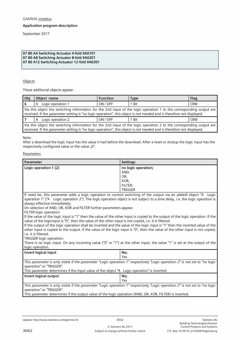
Objects
These additional objects appear.
Obj Object name Function Type Flag
6 A Logic operation 1 ON / OFF 1 Bit CRW
Via this object the switching information for the 2nd input of the logic operation 1 to the corresponding output arereceived. If the parameter setting is "no logic operation", this object is not needed and is therefore not displayed.
7 A Logic operation 2 ON / OFF 1 Bit CRW
Via this object the switching information for the 2nd input of the logic operation 2 to the corresponding output arereceived. If the parameter setting is "no logic operation", this object is not needed and is therefore not displayed.
Note:After a download the logic input has the value it had before the download. After a reset or stratup the logic input has therespectively configured value or the value „0“.
Parameters
Parameter Settings
Logic operation 1 (2) no logic operation;AND;OR;XOR;FILTER;TRIGGER
If need be, this parameter adds a logic operation to control switching of the output via an addedl object “A Logicoperation 1” (“A Logic operation 2”). The logic operation object is not subject to a time delay, i.e. the logic operation isalways effective immediately.On selection of AND, OR, XOR and FILTER further parameters appear.FILTER logic operation:If the value of the logic input is “1” then the value of the other input is copied to the output of the logic operation. If thevalue of the logicinput is “0”, then the value of the other input is not copied, i.e. it is filtered.If the output of the logic operation shall be inverted and the value of the logic input is “1” then the inverted value of theother input is copied to the output. If the value of the logic input is “0”, then the value of the other input is not copied,i.e. it is filtered.TRIGGER logic operation:There is no logic input. On any incoming value (“0” or “1”) at the other input, the value “1” is set at the output of thelogic operation.
Invert logical input No;Yes
This parameter is only visble if the parameter “Logic operation 1” respectively “Logic operation 2” is not set to “no logicoperation” or “TRIGGER”.This parameter determines if the input value of the object “A Logic operation” is inverted.
Invert logical output No;Yes
This parameter is only visble if the parameter “Logic operation 1” respectively “Logic operation 2” is not set to “no logicoperation” or “TRIGGER”.This parameter determines if the output value of the logic operation (AND, OR, XOR, FILTER) is inverted.

GAMMA instabus
Application program description
September 2017
07 B0 A4 Switching Actuator 4-fold 9A010107 B0 A8 Switching Actuator 8-fold 9A020107 B0 A12 Switching Actuator 12-fold 9A0301
Siemens AG DS02 Update: http://www.siemens.com/gamma-tdBuilding Technologies DivisionControl Products and Systems Siemens AG 2017
P.O. Box 10 09 53, D-93009 Regensburg Subject to change without further notice 31/62
Parameter Settings
Initial value of logic operation object after bus voltagerecovery
Off;On;as before voltage failure
This parameter is only visble if the parameter “Logic operation 1” respectively “Logic operation 2” is not set to “no logicoperation” or “TRIGGER”.This parameter determines the initial value of logic input objectafter bus voltage recovery.If the parameter is set to “as before bus voltage failure”, then the logic input is set to the value of the logic input objectstored at bus voltage failure.

GAMMA instabus
Application program description
September 2017
07 B0 A4 Switching Actuator 4-fold 9A010107 B0 A8 Switching Actuator 8-fold 9A020107 B0 A12 Switching Actuator 12-fold 9A0301
Update: http://www.siemens.com/gamma-td DS02 Siemens AGBuilding Technologies Division
Siemens AG 2017 Control Products and Systems
32/62 Subject to change without further notice P.O. Box 10 09 53, D-93009 Regensburg
Central switching
Logic operation 1
Logic operation 2
Central switching
8-bit scene
Logic operation 1
Logic operation 2
t
8-bit scene
0 1Flashing
Central switching
Objects
These additional objects appear.
Obj Object name Function Type Flag
8 A Central switching ON / OFF 1 Bit CW
Via this object central switching commandas are received for this output.
Parameter „Functions, Objects“
Parameter Settings
Central switching Disable;Enalbe
This parameter determines if central switching and the corresponding object is available for this output.
Parameter „Normal mode“
Parameter Settings
ON delay (central switching)[hh:mm:ss]
00:00:00[00:00:00...23:59:59]
This paramerter is only visible if the parameter for “central switching” in the parameter window “Functions, objects” isset to “Enable”.This parameter determines the desired wanted on-delay time for central switching. The default value 00:00:00 meansthat ON commands are executed immediately. A set on-delay acts only on the "Central switching" object.
OFF delay (central switching)[hh:mm:ss]
00:00:00[00:00:00...23:59:59]
This paramerter is only visible if the parameter for “central switching” in the parameter window “Functions, objects” isset to “Enable”.This parameter determines the desired off-delay time for central switching. The default value 00:00:00 means that Offcommands are executed immediately. A set on-delay acts only on the "Central switching" object.
GAMMA instabus
Application program description
September 2017
07 B0 A4 Switching Actuator 4-fold 9A010107 B0 A8 Switching Actuator 8-fold 9A020107 B0 A12 Switching Actuator 12-fold 9A0301
Siemens AG DS02 Update: http://www.siemens.com/gamma-tdBuilding Technologies DivisionControl Products and Systems Siemens AG 2017
P.O. Box 10 09 53, D-93009 Regensburg Subject to change without further notice 33/62
8-bit scene control
Logic operation 2
Central switching
8-bit scene
Night mode
Logic operation 2
t
8-bit scene
0 1Flashing
0 1
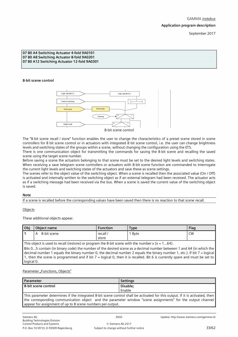
8-bit scene control
The "8-bit scene recall / store" function enables the user to change the characteristics of a preset scene stored in scenecontrollers for 8 bit scene control or in actuators with integrated 8 bit scene control, i.e. the user can change brightnesslevels and switching states of the groups within a scene, without changing the configuration using the ETS.There is one communication object for transmitting the commands for saving the 8-bit scene and recalling the savedscene using the target scene number.Before saving a scene the actuators belonging to that scene must be set to the desired light levels and switching states.When receiving a save telegram scene controllers or actuators with 8-bit scene function are commanded to interrogatethe current light levels and switching states of the actuators and save these as scene settings.The scenes refer to the object value of the switching object. When a scene is recalled then the associated value (On / Off)is activated and internally written to the switching object as if an external telegram had been received. The actuator actsas if a switching message had been received via the bus. When a scene is saved the current value of the switching objectis saved.
Note
If a scene is recalled before the corresponding values have been saved then there is no reaction to that scene recall.
Objects
These additional objects appear.
Obj Object name Function Type Flag
1 A 8-bit scene recall /store
1 Byte CW
This object is used to recall (restore) or program the 8-bit scene with the number x (x = 1...64).Bits 0...5 contain (in binary code) the number of the desired scene as a decimal number between 1 and 64 (in which thedecimal number 1 equals the binary number 0, the decimal number 2 equals the binary number 1, etc.). If bit 7 = logical1, then the scene is programmed and if bit 7 = logical 0, then it is recalled. Bit 6 is currently spare and must be set tological 0.
Parameter „Functions, Objects“
Parameter Settings8-bit scene control Disable;
EnableThis parameter determines if the integrated 8-bit scene control shall be activated for this output. If it is activated, thenthe corresponding communication object and the parameter window “scene assignments” for the output channelappear for assignment of up to 8 scene numbers per output.

GAMMA instabus
Application program description
September 2017
07 B0 A4 Switching Actuator 4-fold 9A010107 B0 A8 Switching Actuator 8-fold 9A020107 B0 A12 Switching Actuator 12-fold 9A0301
Update: http://www.siemens.com/gamma-td DS02 Siemens AGBuilding Technologies Division
Siemens AG 2017 Control Products and Systems
34/62 Subject to change without further notice P.O. Box 10 09 53, D-93009 Regensburg
Parameter „Scene assignments“
Parameter Settings
Link 1 with scene [0...64](0 = disable)
01 … 64
Link 2 with scene [0...64](0 = disable)
01 … 64
Link 3 with scene [0...64](0 = disable)
01 … 64
Link 4 with scene [0...64](0 = disable)
01 … 64
Link 5 with scene [0...64](0 = disable)
01 … 64
Link 6 with scene [0...64](0 = disable)
01 … 64
Link 7 with scene [0...64](0 = disable)
01 … 64
Link 8 with scene [0...64](0 = disable)
01 … 64
Each of these parameters assigns the output of the actuator to an 8-bit scene with a number in the range of 1 to 64. ”0“means that the specific assignment is not used.Note: If a scene is recalled before the corresponding values have been saved then there is no reaction to that scenerecall.
8-bit scenes configurable by user Disable;Enable
This parameter is visible for an active link (i.e. the value for Link is [1…64]).Disable:If “Disable” is selected, then the scenes cannot be set via an 8-bit scene telegram. The values, which are predefined viathe parameter „Predefined switching value for scene“ for the relay position on recall of the scene, cannot be changedduring operation.Enable:
If “Enable” is selected, then the parameter “Delete learned scene” is visble.

GAMMA instabus
Application program description
September 2017
07 B0 A4 Switching Actuator 4-fold 9A010107 B0 A8 Switching Actuator 8-fold 9A020107 B0 A12 Switching Actuator 12-fold 9A0301
Siemens AG DS02 Update: http://www.siemens.com/gamma-tdBuilding Technologies DivisionControl Products and Systems Siemens AG 2017
P.O. Box 10 09 53, D-93009 Regensburg Subject to change without further notice 35/62
Parameter SettingsDelete learned scene Disable;
EnableThis parameter is viisble for an active link if the parameter “8-bit scenes configurable by user”is set to “Enable”.
Disable:If “Disable” is selected, then the learned scenes are not deleted when the configuration is loaded into the device.Enable:If “Enable” is selected, then then the learned scenes are deleted when the configuration is loaded into the device.Predefine scene Disable;
EnableThis parameter is viisble for an active link if the parameter “8-bit scenes configurable by user”is set to “Enable” and theparameters “Delete learned scene” is set to “Enable”.Disable:If “Disable” is selected, then the parameter “Predefined switching value for scene” becomes invisible. A scene must beteached in by the user. Already learned scene values are deleted when the configuration is loaded into the device. If novalue is learned then the scene is not activated.Enable:If “Enable” is selected, then the parameter “Predefined switching value for scene” becomes visible. The value selected as“Predefined switching value for scene” is loaded into the device as scene value when the device configuration is loadedinto the device.Predefined switching value for scene Off;
OnThis parameter is viisble for an active link if the parameter “8-bit scenes configurable by user”is set to “Disable” or if theparameters “8-bit scenes configurable by user”, “Delete learned scene” and “Predefine scene” are set to “Enable”.This parameter determines the switching value of the scene number preset during configuration and loaded into thedevice with ETS.

GAMMA instabus
Application program description
September 2017
07 B0 A4 Switching Actuator 4-fold 9A010107 B0 A8 Switching Actuator 8-fold 9A020107 B0 A12 Switching Actuator 12-fold 9A0301
Update: http://www.siemens.com/gamma-td DS02 Siemens AGBuilding Technologies Division
Siemens AG 2017 Control Products and Systems
36/62 Subject to change without further notice P.O. Box 10 09 53, D-93009 Regensburg
Night mode
Night mode
Day mode timer period
Night mode timer period
0 1Flashing
0 1
Day mode timer FlashingNight mode timer
Override control 1Override control 1 Status Override control 1
Night mode
Via an optional object “Night mode” for each output, it can be, if desired, controlled to switch on for a limited time only(e.g. for cleaning crew lighting) instead of permanently switching on. The time limited switching may be configured withwarning before turning off with repeated off-on-switching of the output (flashing).
Objects
These additional objects appear.
Obj Object name Function Type Flag
10 A Night mode ON / OFF 1 Bit CWThis object enables or disables "Night mode" for the corresponding output via the bus. The control signal can be sent bya button, a timer or an automatic building management system, for example. If a logical one is received, then thecorresponding output switches to night mode.In "Night mode" the output can no longer be switched on permanently, but only for a limited time (for example, lightingfor cleaning for 30 minutes). If the "Warning before switching off" parameter (see corresponding "Normal operation"parameter window) is set to "Yes" then, in night or day timer mode, before the configured ON time has elapsed, you areinformed, by the lighting switching off and on again, that e.g. approximately 30 seconds after the first switching off theoutput will be switched off permanently. This lets you know the end of the ON time and by pressing the light switchagain, the lighting will be left ON for a further 30 minutes, for example. If the parameter setting is "Night mode = No",this object is not needed and is therefore not displayed.
11 A night mode timer ON time(seconds)
2 Byte (DPT 7.005) CRW
Via this object the ON time for this output in the „Night mode“ can be changed via the bus. The time is set in seconds.Note:Different from the ETS parameter, because of the DPT, the timer cannot be set to 23:59:59.
15 A Lock timer On / Off 1 Bit CWVia this object the „Night mode“ for this output can be locked respectively released via the bus. This allows for turningthe night mode off when necessary.
Parameter
Parameter Settings
Night mode Disable;Enable
This parameter determines whether an additional "Night mode" communication object is activated for this output. Ifnight mode is on, the output can no longer be switched on permanently but only for a time-limited period (e.g. forlighting for cleaning).

GAMMA instabus
Application program description
September 2017
07 B0 A4 Switching Actuator 4-fold 9A010107 B0 A8 Switching Actuator 8-fold 9A020107 B0 A12 Switching Actuator 12-fold 9A0301
Siemens AG DS02 Update: http://www.siemens.com/gamma-tdBuilding Technologies DivisionControl Products and Systems Siemens AG 2017
P.O. Box 10 09 53, D-93009 Regensburg Subject to change without further notice 37/62
Parameter Settings
If you set this parameter to "Enable", then the following parameters "On-time during night mode in hh:mm:ss" and"Warn before switching off" are added.
ON time during night mode[hh:mm:ss]
00:30:00[00:00:00 … 23:59:59]
This parameter determines the ON time during night mode of the output.
Retriggering possible 1[0…5]
This parameter determines whether the On period is restarted and thus the On time is to be extended when a new Ontelegram is received during an On period.If the parameter is set to “0” then an extension is not possible during the On period.Additionally, it ispossible to determine how long the On period can be extended at maximum by receiving severalswitching telegrams. Thus the maximum settable period is:1: up to max. 1x ON time2: up to max. 2x ON time3: up to max. 3x ON time4: up to max. 4x ON time5: up to max. 5x ON time
Warning before switching Off No;via briefly switching On – Off;via communication object;via briefly switching On – Off and via communicationobject;
This parameter determines whether at the end of the On time the output immediately shall be turned off permanentlyor if a warning shall happen before the output switching off.„No“:
The output is immediately switched Off without warning.
With the following parameter settings the output is not immediately switched Off permanently.If the output is used for lighting control then the user is warned and has ample time to extend the On period of thelighting or if need be turn it on again.„via briefly switching On – Off“:
The output is switched off for the configurable warning signal period (default setting: 1s) and then switched on againfor a configurable time (difference of parameter „warning period“ – parameter „warning signal period“).Note:The „warning signal period“ shall not be longer than the „warning period“ because otherwise no warning willoccur!If within the warning period the output is switched on again via e.g. the object „switching“ then the timer On periodstarts again. Otherwise, the output is switched off.
„via communciation object“:Via this selection the communication object „Pre-warning expiration of timer period” appears, which can be used tosend a pre-warning onto the bus e.g. to switch on a warning lamp.The expiration of the On period of the timer is signaled via the communication object. At the same time the warningperiod starts with a period defined by the parameter “warning period”. The output is not briefly switched on/off.If within the warning period the output is switched on again via e.g. the object „switching“ then the timer On periodstarts again. Otherwise, the output is switched off.
via briefly switching On – Off and via communication object:Via this selection the communication object „Pre-warning expiration of timer period” appears, which can be used tosend a pre-warning onto the bus e.g. to switch on a warning lamp.The expiration of the On period of the timer is signaled via the communication object. The output is switched off forthe configurable warning signal period (default setting: 1s) and then switched on again for a configurable time

GAMMA instabus
Application program description
September 2017
07 B0 A4 Switching Actuator 4-fold 9A010107 B0 A8 Switching Actuator 8-fold 9A020107 B0 A12 Switching Actuator 12-fold 9A0301
Update: http://www.siemens.com/gamma-td DS02 Siemens AGBuilding Technologies Division
Siemens AG 2017 Control Products and Systems
38/62 Subject to change without further notice P.O. Box 10 09 53, D-93009 Regensburg
Parameter Settings
(difference of parameter „warning period“ – parameter „warning signal period“).Note:The „warning signal period“ shall not be longer than the „warning period“ because otherwise no warning willoccur!If within the warning period the output is switched on again via e.g. the object „switching“ then the timer On periodstarts again. Otherwise, the output is switched off.
Warning period[hh:mm:ss]
00:00:30[00:00:01…18:12:15]
This parameter is only visible if the parameter „Warning before switching Off“is not set to „No“.This parameter determines the warning period during which the output stays switched On after the timer expired.
Warning signal period[hh:mm:ss]
00:00:01[00:00:01…18:12:15]
This parameter is only visible if the parameter „warning before switching Off“ is set to „via briefly switching On – Off“ or„via briefly switching On – Off and via communication object“.This parameter determines that, after the On period has expired, the output is not immediately switched offpermanently but only switched off for a warning signal period (default setting: 1 second) and then switched on againfor a configurable time (parameter „warning period“). After this warning period has expired the output is switched offpermanently. If the output is used for lighting control then the user is warned and has ample time to extend the Onperiod of the lighting or, if need be, turn it on again.
Change ON time in night mode via object Disable;Enable
This parameter determines if the object “Night mode timer” is available.
Blocking characteristics for time mode Deactivate timer;Reset timer;Pause timer;no blocking
This parameter determines the blocking behavior in timer operation mode.„no blocking“:
Blocking of the timer is not possible.If one of the following parameter settings is selected then a blocking object for the timer appears.„Pause timer“:
Triggered timer functions are halted and continue running after release of the blocking object at the time when thewere halted.
„Reset timer“:Triggered timer functions are halted. After release of the blocking object the timer is reset and restarted again.
„Deactivate timer“:Triggered timer functions are stopped. After release of the blocking object the timer is neither continued nor restart-ed.

GAMMA instabus
Application program description
September 2017
07 B0 A4 Switching Actuator 4-fold 9A010107 B0 A8 Switching Actuator 8-fold 9A020107 B0 A12 Switching Actuator 12-fold 9A0301
Siemens AG DS02 Update: http://www.siemens.com/gamma-tdBuilding Technologies DivisionControl Products and Systems Siemens AG 2017
P.O. Box 10 09 53, D-93009 Regensburg Subject to change without further notice 39/62
Override
Day mode timer period
Night mode timer period
Forced control
Day mode timer FlashingNight mode timer
Override control 1
Override control 2
Override control 3
Override control 4
Override control 5
Forced control
Override control 6
Override control 5
Override control 4
Override control 3
Override control 2
Override control 1
Override control 6
Status Override control 1
Status Override control 2
Status Override control 3
Status Override control 4
Status Override control 5
Status Override control 6
Status Forced control
NO / NC contact
Override functions
Per output channel up to 6 override funtions and a forced control function can be activated. These override functions areavailable:⇔ Manual override (ON)⇔ Permanent OFF⇔ Lock⇔ Central override⇔ User-defined Control
The priority of the override functions is determined by the position in the line of execution. Override 6 has the highestpriority, whereas override 1 has the lowest priority.The forced control function available for each output is situated in the line of execution between overrides 5 and 6 andthus has the second highest priority.
As the objects and parameters for the 6 override functions are the same, only the objects and parameters for override 1are described below.
Parameter „Functions, Objects“
Parameter Settings
Override 1 deactivated;Manual override (ON);Permanent OFF;Lock;Central override;User defined
This parameter determines for override function block 1, which override function is activated.When “deactivated” is selected, then the override function block is not present and the parameter window not visible.If one of the other options is selected then the parameter window for that override function block is visible and showsthe parameters for the selected override function.The associated objects and parameters for the respective override function are described in the following sections.

GAMMA instabus
Application program description
September 2017
07 B0 A4 Switching Actuator 4-fold 9A010107 B0 A8 Switching Actuator 8-fold 9A020107 B0 A12 Switching Actuator 12-fold 9A0301
Update: http://www.siemens.com/gamma-td DS02 Siemens AGBuilding Technologies Division
Siemens AG 2017 Control Products and Systems
40/62 Subject to change without further notice P.O. Box 10 09 53, D-93009 Regensburg
--- Manual override (ON)
Manual override ON
01
0 1
t
Control value input
Status Override control
Send status value
Manual override ON, Controlvalue
1 0
„1"
Manual override
Objects
These additional objects appear.
Obj Object name Function Type Flag
16 A Override 1, Manual ON ON / OFF 1 Bit CW
This object and further objects are only visble if the parameter „Override 1“ in the parameter window „Functions,objects“ is set to „Manual override (ON)“ and the parameter „Control Value Input“ is set to „Disable“.This object enables to switch an output on permanently or for a time-limited period if it has been switched OFF via its"normal" switching input (if need be, in conjunction with a logic operation).Manual (ON) is active if the value of the object is “On”.
If an invertion of the object value is configured, then Manual (ON) is active when the object value is “Off”.The output is only switched off via this object, if the output would be switched off via its "normal" switching input (ifneed be, with a logic operation). Otherwise, the output remains switched on.
17 A Override 1, Manual ON, Controlvalue
Value 1 Byte (Percent 0 … 100%) (DPT5.001)1 Byte (Count pulses 0 … 255) (DPT5.010)2 Byte (Temperature °C) (DPT 9.001)2 Byte (Illuminance lx) (DPT 9.004)2 Byte (Current mA) (DPT 9.021)4 Byte (Power W) (DPT14.056)2 Byte (Power kW) (DPT 9.024)
CW
This object is only visble if the parameter „Control Value Input“ in the parameter window „Override 1“ is set to „Enable“.
Via this object a control value can be used as input value for the override.
18 A Override 1, Manual ON, Status ON / OFF 1 Bit CRT
This object is only visble if the parameter „Status Override“ in the parameter window „Override 1“ is set to „Enable“.Via this object the status of the override (active or inactive) can be annunciated.

GAMMA instabus
Application program description
September 2017
07 B0 A4 Switching Actuator 4-fold 9A010107 B0 A8 Switching Actuator 8-fold 9A020107 B0 A12 Switching Actuator 12-fold 9A0301
Siemens AG DS02 Update: http://www.siemens.com/gamma-tdBuilding Technologies DivisionControl Products and Systems Siemens AG 2017
P.O. Box 10 09 53, D-93009 Regensburg Subject to change without further notice 41/62
Parameter
Parameter Settings
Control Value Input Disable;Enable
This parameter determines if a Control Value Input shall be used instead of the switching input for activation or deacti-vation of the override function.See section “Control Value Input” for further parameters that become visible.
Invert Override Control No;Yes
This parameter determines whether the input value of the override object is used direct or as inverted value.
Override Duration[ hh:mm:ss]
00:00:00[00:00:00…18:12:15]
This parameter determines the desired duration for switching the output on via manual override.The override period is restarted with each incoming activation telegram.The override period is indefinite if the parameter value is 00:00:00.
Status Override Disable;Enable
This parameter determines if a status object shall become visible. Via this object the status (active / inactive) of theoverride is annunciated.See section “Status annunciation” for further parameters that become visible.
Note: On bus voltage recovery the override function “Manual Override (ON)” is deactivated.

GAMMA instabus
Application program description
September 2017
07 B0 A4 Switching Actuator 4-fold 9A010107 B0 A8 Switching Actuator 8-fold 9A020107 B0 A12 Switching Actuator 12-fold 9A0301
Update: http://www.siemens.com/gamma-td DS02 Siemens AGBuilding Technologies Division
Siemens AG 2017 Control Products and Systems
42/62 Subject to change without further notice P.O. Box 10 09 53, D-93009 Regensburg
--- Permanent OFF
Permanent OFF
01
0 1
t
Control value input
Status Override control
Send status value
Permanent OFF, Controlvalue
1 0
„0"
Permanent Off
Objects
These additional objects appear.
Obj Object name Function Type Flag
16 A Override 1, Permanent OFF ON / OFF 1 Bit CW
This object and further objects are only visble if the parameter „Override 1“ in the parameter window „Functions,objects“ is set to „Permanent OFF“ and the parameter „Control Value Input“ is set to „Disable“.This object enables to switch an output off permanently independent of the preceding partial functions.Permanent OFF is active if the value of the object is “On”.
If an invertion of the object value is configured, then Permanent OFF is active when the object value is “Off”.The output is only switched on via this object, if the output would be switched on via its "normal" switching input (ifneed be, with a logic operation). Otherwise, the output remains switched off.
17 A Override 1, Permanent OFF,Control value
Value 1 Byte (Percent 0 … 100%) (DPT5.001)1 Byte (Count pulses 0 … 255) (DPT5.010)2 Byte (Temperature °C) (DPT 9.001)2 Byte (Illuminance lx) (DPT 9.004)2 Byte (Current mA) (DPT 9.021)4 Byte (Power W) (DPT14.056)2 Byte (Power kW) (DPT 9.024)
CW
This object is only visble if the parameter „Control Value Input“ in the parameter window „Override 1“ is set to „Enable“.
Via this object a control value can be used as input value for the override.
18 A Override 1, Permanent OFF,Status
ON / OFF 1 Bit CRT
This object is only visble if the parameter „Status Override“ in the parameter window „Override 1“ is set to „Enable“.Via this object the status of the override (active or inactive) can be annunciated.

GAMMA instabus
Application program description
September 2017
07 B0 A4 Switching Actuator 4-fold 9A010107 B0 A8 Switching Actuator 8-fold 9A020107 B0 A12 Switching Actuator 12-fold 9A0301
Siemens AG DS02 Update: http://www.siemens.com/gamma-tdBuilding Technologies DivisionControl Products and Systems Siemens AG 2017
P.O. Box 10 09 53, D-93009 Regensburg Subject to change without further notice 43/62
Parameter
Parameter Settings
Control Value Input Disable;Enable
This parameter determines if a Control Value Input shall be used instead of the switching input for activation or deacti-vation of the override function.See section “Control Value Input” for further parameters that become visible.
Invert Override Control No;Yes
This parameter determines whether the input value of the object “Override 1, Permanent OFF” is used direct or asinverted value.
Status Override Disable;Enable
This parameter determines if a status object shall become visible. Via this object the status (active / inactive) of theoverride is annunciated.See section “Status annunciation” for further parameters that become visible.
Start value / behavior of override input on bus voltagerecovery
Off;On;deactivated;Last value
This parameter determines the desired start value / behavior of the input of the function block „Override 1, PermanentOFF“ on bus voltage recovery.If the parameter is set to „deactivated“, then the override function block is deactivated on bus voltage recovery.If the parameter is set to „last value“, then the input of the override function block is set to the value saved on busvoltage failure.

GAMMA instabus
Application program description
September 2017
07 B0 A4 Switching Actuator 4-fold 9A010107 B0 A8 Switching Actuator 8-fold 9A020107 B0 A12 Switching Actuator 12-fold 9A0301
Update: http://www.siemens.com/gamma-td DS02 Siemens AGBuilding Technologies Division
Siemens AG 2017 Control Products and Systems
44/62 Subject to change without further notice P.O. Box 10 09 53, D-93009 Regensburg
--- Lock
Locking function
01
0 1Control value input
Status Override control
Send status value
Locking function, Controlvalue
1 0
„Locking"
Lock
Objects
These additional objects appear.
Obj Object name Function Type Flag
16 A Override 1, Lock ON / OFF 1 Bit CW
This object and further objects are only visble if the parameter „Override 1“ in the parameter window „Functions,objects“ is set to „Lock“ and the parameter „Control Value Input“ is set to „Disable“.This object enables to lock an output against changes from preceding partial functions as long as the lock is set.Lock is active if the value of the object is “On”.
If an invertion of the object value is configured, then Lock is active when the object value is “Off”.On deactivation of the lock the current value of the processed function chain is transfered from the input of the functionblock to the output. After the lock has been released the last received value is processed.
The lock object effects that all preceding function blocks internally save their values, but these are not processed andsent.
17 A Override 1, Lock, Control value Value 1 Byte (Percent 0 … 100%) (DPT5.001)1 Byte (Count pulses 0 … 255) (DPT5.010)2 Byte (Temperature °C) (DPT 9.001)2 Byte (Illuminance lx) (DPT 9.004)2 Byte (Current mA) (DPT 9.021)4 Byte (Power W) (DPT14.056)2 Byte (Power kW) (DPT 9.024)
CW
This object is only visble if the parameter „Control Value Input“ in the parameter window „Override 1“ is set to „Enable“.Via this object a control value can be used as input value for the override.
18 A Override 1, Lock, Status ON / AUS 1 Bit CRT
This object is only visble if the parameter „Status Override“ in the parameter window „Override 1“ is set to „Enable“.Via this object the status of the override (active or inactive) can be annunciated.

GAMMA instabus
Application program description
September 2017
07 B0 A4 Switching Actuator 4-fold 9A010107 B0 A8 Switching Actuator 8-fold 9A020107 B0 A12 Switching Actuator 12-fold 9A0301
Siemens AG DS02 Update: http://www.siemens.com/gamma-tdBuilding Technologies DivisionControl Products and Systems Siemens AG 2017
P.O. Box 10 09 53, D-93009 Regensburg Subject to change without further notice 45/62
Parameter
Parameter Settings
Control Value Input Disable;Enable
This parameter determines if a Control Value Input shall be used instead of the switching input for activation or deacti-vation of the override function.See section “Control Value Input” for further parameters that become visible.
Invert Override Control No;Yes
This parameter determines whether the input value of the object “Override 1, Lock” is used direct or as inverted value.
Status Override Disable;Enable
This parameter determines if a status object shall become visible. Via this object the status (active / inactive) of theoverride is annunciated.See section “Status annunciation” for further parameters that become visible.
Note: On bus voltage recovery the override function “Lock” takes the same state as before bus voltage failure.
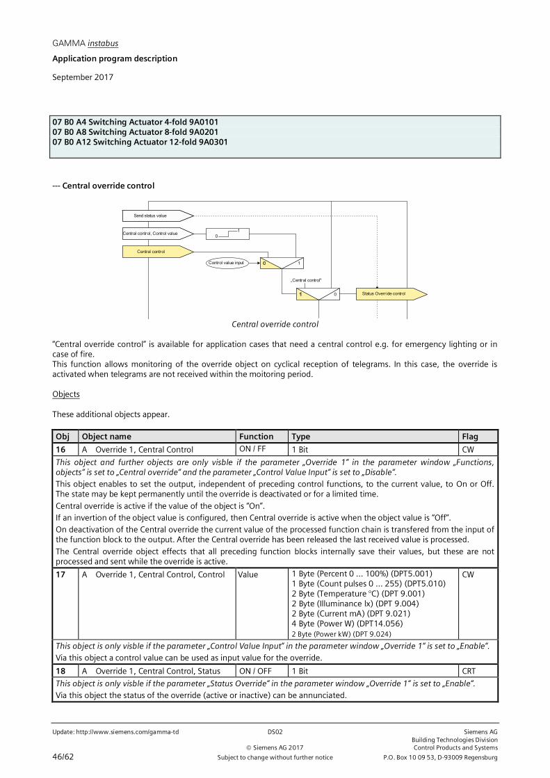
GAMMA instabus
Application program description
September 2017
07 B0 A4 Switching Actuator 4-fold 9A010107 B0 A8 Switching Actuator 8-fold 9A020107 B0 A12 Switching Actuator 12-fold 9A0301
Update: http://www.siemens.com/gamma-td DS02 Siemens AGBuilding Technologies Division
Siemens AG 2017 Control Products and Systems
46/62 Subject to change without further notice P.O. Box 10 09 53, D-93009 Regensburg
--- Central override control
Central control
01
0 1Control value input
Status Override control
Send status value
Central control, Control value
1 0
„Central control"
Central override control
“Central override control” is available for application cases that need a central control e.g. for emergency lighting or incase of fire.This function allows monitoring of the override object on cyclical reception of telegrams. In this case, the override isactivated when telegrams are not received within the moitoring period.
Objects
These additional objects appear.
Obj Object name Function Type Flag
16 A Override 1, Central Control ON / FF 1 Bit CW
This object and further objects are only visble if the parameter „Override 1“ in the parameter window „Functions,objects“ is set to „Central override“ and the parameter „Control Value Input“ is set to „Disable“.This object enables to set the output, independent of preceding control functions, to the current value, to On or Off.The state may be kept permanently until the override is deactivated or for a limited time.
Central override is active if the value of the object is “On”.If an invertion of the object value is configured, then Central override is active when the object value is “Off”.On deactivation of the Central override the current value of the processed function chain is transfered from the input ofthe function block to the output. After the Central override has been released the last received value is processed.
The Central override object effects that all preceding function blocks internally save their values, but these are notprocessed and sent while the override is active.
17 A Override 1, Central Control, Control Value 1 Byte (Percent 0 … 100%) (DPT5.001)1 Byte (Count pulses 0 … 255) (DPT5.010)2 Byte (Temperature °C) (DPT 9.001)2 Byte (Illuminance lx) (DPT 9.004)2 Byte (Current mA) (DPT 9.021)4 Byte (Power W) (DPT14.056)2 Byte (Power kW) (DPT 9.024)
CW
This object is only visble if the parameter „Control Value Input“ in the parameter window „Override 1“ is set to „Enable“.Via this object a control value can be used as input value for the override.
18 A Override 1, Central Control, Status ON / OFF 1 Bit CRT
This object is only visble if the parameter „Status Override“ in the parameter window „Override 1“ is set to „Enable“.Via this object the status of the override (active or inactive) can be annunciated.
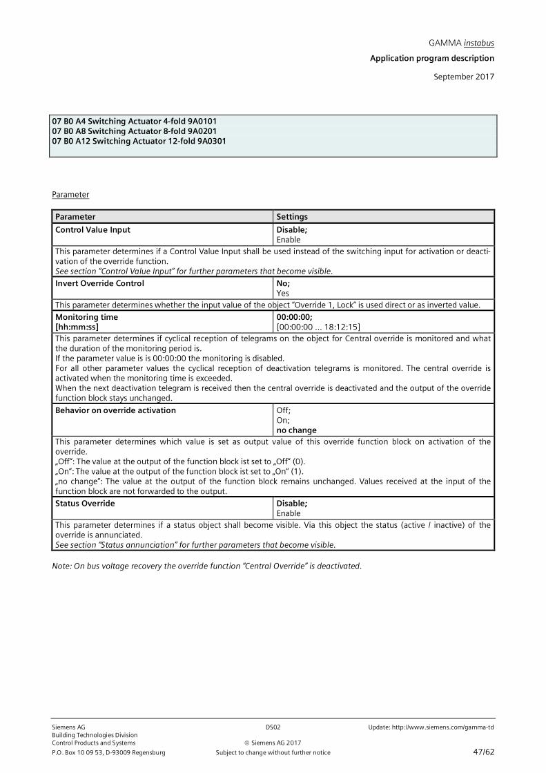
GAMMA instabus
Application program description
September 2017
07 B0 A4 Switching Actuator 4-fold 9A010107 B0 A8 Switching Actuator 8-fold 9A020107 B0 A12 Switching Actuator 12-fold 9A0301
Siemens AG DS02 Update: http://www.siemens.com/gamma-tdBuilding Technologies DivisionControl Products and Systems Siemens AG 2017
P.O. Box 10 09 53, D-93009 Regensburg Subject to change without further notice 47/62
Parameter
Parameter Settings
Control Value Input Disable;Enable
This parameter determines if a Control Value Input shall be used instead of the switching input for activation or deacti-vation of the override function.See section “Control Value Input” for further parameters that become visible.
Invert Override Control No;Yes
This parameter determines whether the input value of the object “Override 1, Lock” is used direct or as inverted value.
Monitoring time[hh:mm:ss]
00:00:00;[00:00:00 … 18:12:15]
This parameter determines if cyclical reception of telegrams on the object for Central override is monitored and whatthe duration of the monitoring period is.If the parameter value is is 00:00:00 the monitoring is disabled.For all other parameter values the cyclical reception of deactivation telegrams is monitored. The central override isactivated when the monitoring time is exceeded.When the next deactivation telegram is received then the central override is deactivated and the output of the overridefunction block stays unchanged.
Behavior on override activation Off;On;no change
This parameter determines which value is set as output value of this override function block on activation of theoverride.„Off“: The value at the output of the function block ist set to „Off“ (0).„On“: The value at the output of the function block ist set to „On“ (1).„no change“: The value at the output of the function block remains unchanged. Values received at the input of thefunction block are not forwarded to the output.
Status Override Disable;Enable
This parameter determines if a status object shall become visible. Via this object the status (active / inactive) of theoverride is annunciated.See section “Status annunciation” for further parameters that become visible.
Note: On bus voltage recovery the override function “Central Override” is deactivated.

GAMMA instabus
Application program description
September 2017
07 B0 A4 Switching Actuator 4-fold 9A010107 B0 A8 Switching Actuator 8-fold 9A020107 B0 A12 Switching Actuator 12-fold 9A0301
Update: http://www.siemens.com/gamma-td DS02 Siemens AGBuilding Technologies Division
Siemens AG 2017 Control Products and Systems
48/62 Subject to change without further notice P.O. Box 10 09 53, D-93009 Regensburg
--- User-defined override function
User-defined control
01
0 1Control value input
Status Override control
Send status value
User-defined control, Controlvalue
1 0
„User-definedcontrol"
User-defined override function
“User-defined override function” is available for application cases, where none of the pre-defined override functionsManual ON, Permanent OFF, Lock, Central override can be applied.
Objects
These additional objects appear.
Obj Object name Function Type Flag
16 A Override 1, Used-defined Control ON / OFF 1 Bit CW
This object and further objects are only visble if the parameter „Override 1“ in the parameter window „Functions,objects“ is set to „User defined“ and the parameter „Control Value Input“ is set to „Disable“.
This object enables to set the output, independent of preceding control functions, to the current value, to On or Off.The state may be kept permanently until the override is deactivated or for a limited time.User-defined override is active if the value of the object is “On”.If an invertion of the object value is configured, then User-defined override is active when the object value is “Off”.
On deactivation of the User-defined override the current value of the processed function chain is transfered from theinput of the function block to the output. After the user-defined override has been released the last received value isprocessed.The user-defined override object effects that all precding function blocks internally save their values, but these are notprocessed and sent while the override is active.
17 A Override 1, Used-defined Control,Control value
Value 1 Byte (Percent 0 … 100%) (DPT5.001)1 Byte (Count pulses 0 … 255) (DPT5.010)2 Byte (Temperature °C) (DPT 9.001)2 Byte (Illuminance lx) (DPT 9.004)2 Byte (Current mA) (DPT 9.021)4 Byte (Power W) (DPT14.056)2 Byte (Power kW) (DPT 9.024)
CW
This object is only visble if the parameter „Control Value Input“ in the parameter window „Override 1“ is set to „Enable“.Via this object a control value can be used as input value for the override.

GAMMA instabus
Application program description
September 2017
07 B0 A4 Switching Actuator 4-fold 9A010107 B0 A8 Switching Actuator 8-fold 9A020107 B0 A12 Switching Actuator 12-fold 9A0301
Siemens AG DS02 Update: http://www.siemens.com/gamma-tdBuilding Technologies DivisionControl Products and Systems Siemens AG 2017
P.O. Box 10 09 53, D-93009 Regensburg Subject to change without further notice 49/62
Obj Object name Function Type Flag
18 A Override 1, Used-defined Control,Status
ON / OFF 1 Bit CRT
This object is only visble if the parameter „Status Override“ in the parameter window „Override 1“ is set to „Enable“.Via this object the status of the override (active or inactive) can be annunciated.
Parameter
Parameter Settings
Control Value Input Disable;Enable
This parameter determines if a Control Value Input shall be used instead of the switching input for activation or deacti-vation of the override function.See section “Control Value Input” for further parameters that become visible.
Invert Override Control No;Yes
This parameter determines whether the input value of the object “Override 1, Lock” is used direct or as inverted value.
Monitoring time[hh:mm:ss]
00:00:00;[00:00:00 … 18:12:15]
This parameter determines if cyclical reception of telegrams on the object for user-defined override is monitored andwhat the duration of the monitoring period is.If the parameter value is is 00:00:00 the monitoring is disabled.For all other parameter values the cyclical reception of deactivation telegrams is monitored. The user-defined override isactivated when the monitoring time is exceeded.When the next deactivation telegram is received then the user-defined override is deactivated according to the parame-ter “Behavior on override deactivation”.
Behavior on override activation Off;On;no change
This parameter determines which value is set as output value of this override function block on activation of theoverride.„Off“: The value at the output of the function block ist set to „Off“ (0).„On“: The value at the output of the function block ist set to „On“ (1).„no change“: The value at the output of the function block remains unchanged. Values received at the input of thefunction block are not forwarded to the output.

GAMMA instabus
Application program description
September 2017
07 B0 A4 Switching Actuator 4-fold 9A010107 B0 A8 Switching Actuator 8-fold 9A020107 B0 A12 Switching Actuator 12-fold 9A0301
Update: http://www.siemens.com/gamma-td DS02 Siemens AGBuilding Technologies Division
Siemens AG 2017 Control Products and Systems
50/62 Subject to change without further notice P.O. Box 10 09 53, D-93009 Regensburg
Parameter Settings
Override Duration[ hh:mm:ss]
00:00:00[00:00:00…18:12:15]
This parameter determines the desired duration for switching the output on via manual override.The override period is restarted with each incoming activation telegram.The override period is indefinite if the parameter value is 00:00:00.
Behavior on override deactivation updated value;no change
This parameter determines which value is set as output value of this override function block on deactivation of theoverride.„Updated value“: The value at the output of the function block ist updated with the input value to the function overrideblock from the preceeding function block.„No change“: The value at the output of the function block remains unchanged. Values received at the input of thefunction block are not forwarded to the output.
Restart timer on deactivation of override Disable;Enable
This parameter is only visible if the parameter “Behavior on override deactivation” is set to “no change”.This parameter determines if a timer (day mode, night mode or delayed on / off) is restarted on deactivation (Enable) ornot (Disable).
Status Override Disable;Enable
This parameter determines if a status object shall become visible. Via this object the status (active / inactive) of theoverride is annunciated.See section “Status annunciation” for further parameters that become visible.
Start value / behavior of override input on bus voltagerecovery
Off;On;deactivated;Last value
This parameter determines the desired start value of input of the function block „Override 1, user-defined control“ onbus voltage recovery.If the parameter is set to „deactivated“, then the override function block is deactivated on bus voltage recovery.If the parameter is set to „last value“, then the input of the override function block is set to the value saved on busvoltage failure.

GAMMA instabus
Application program description
September 2017
07 B0 A4 Switching Actuator 4-fold 9A010107 B0 A8 Switching Actuator 8-fold 9A020107 B0 A12 Switching Actuator 12-fold 9A0301
Siemens AG DS02 Update: http://www.siemens.com/gamma-tdBuilding Technologies DivisionControl Products and Systems Siemens AG 2017
P.O. Box 10 09 53, D-93009 Regensburg Subject to change without further notice 51/62
--- Forced control
Bit
Status Forced control
01 & &
≥1
Forced Control
Forced control
Actuators with forced control allow overriding certain actuator outputs by central control commands. In energy savingsmode or at night turning selected luminaires or loads on may be forced to be blocked.
Objects
These additional objects appear.
Obj Object name Function Type Flag
13 A Forced control ON / OFF 2 Bit CRW
These 2-bit objects enable a forced switching on or off of the corresponding output, regardless of all other objectsimpacting on the output, except for override 6..
Bit 1 determines whether the forced control is "active" (= 1) or "passive" (0). If bit 1 = 0, then the forced control is"passive" and the switching input is available directly at the forced control output. If bit 1 of the forced control object =1, then the forced control is "active" and the switching input is disabled. In this case, bit 0 of the forced control objectdetermines the value of the internal forced control output. If forced control is blocked, the switching input is availabledirectly at the internal output of the forced control function.
Bit 1 Bit 0 Function
0 0 Forced control disabled
0 1 Forced control disabled
1 0 Force controlled OFF
1 1 Force controlled ON

GAMMA instabus
Application program description
September 2017
07 B0 A4 Switching Actuator 4-fold 9A010107 B0 A8 Switching Actuator 8-fold 9A020107 B0 A12 Switching Actuator 12-fold 9A0301
Update: http://www.siemens.com/gamma-td DS02 Siemens AGBuilding Technologies Division
Siemens AG 2017 Control Products and Systems
52/62 Subject to change without further notice P.O. Box 10 09 53, D-93009 Regensburg
Parameter
Parameter Settings
Forced control Disable;Enable
If necessary, you use this parameter to add the 2-bit object "X-n: Forced control", which allows forced switching on oroff of the output, regardless of any other objects acting on the output.Bit 1 determines whether the forced control is "active" (= 1) or "passive" (0). If bit 1 = 0, then the forced control is"passive" and the switching input is available directly at the forced control output. If bit 1 of the forced control object =1, then the forced control is "active" and the switching input is disabled. In this case, bit 0 of the forced control objectdetermines the value of the internal forced control output. If forced control is blocked, the switching input is availabledirectly at the internal output of the forced control function.
Bit 1 Bit 0 Function
0 0 Forced control disabled
0 1 Forced control disabled
1 0 Force controlled OFF
1 1 Force controlled ON

GAMMA instabus
Application program description
September 2017
07 B0 A4 Switching Actuator 4-fold 9A010107 B0 A8 Switching Actuator 8-fold 9A020107 B0 A12 Switching Actuator 12-fold 9A0301
Siemens AG DS02 Update: http://www.siemens.com/gamma-tdBuilding Technologies DivisionControl Products and Systems Siemens AG 2017
P.O. Box 10 09 53, D-93009 Regensburg Subject to change without further notice 53/62
Status annunciation
Override control 6
Status Switching
Number of switchingcycles
Number of operatinghours
Override control 6 Status Override control6
Status
Status Number of switchingcycles
Status Number of operatinghours
NO / NC contact
Status
Objects
These additional objects appear.
Obj Object name Function Type Flag
5 A Status Switching ON / OFF 1 Bit CRT
The current switching state of the corresponding output is stored in the status object and this can be queried by a readrequest or will be sent automatically after each object value change according to the corresponding configuration. If theparameter setting is "Switching status object = no", this object is not needed and is therefore not displayed.
Parameter „Functions, Objects“
Parameter SettingsStatus object Disable;
EnableThis parameter determines whether an "A Status switching" communication object is available for the correspondingoutput. For example, the status object can be used to display the current output switching status on a display, a panel ora PC with visualization software.
Parameter „Functions, Objects“Parameter „Switching cycles“Parameter „Operating hours“
This parameter window allows setting the sending characteristics for status objects.The settings, via the associated parameters, influence the behavior for the objects “A number of switching cycles”, Aoperating hours” respectively “A status object” and “A override”.When threshold monitoring is activated then these settings, via the associated parameters, influence the behavior for theobjects “A Exceedance of threshold for switching cycles” respectively “A Exceedance of threshold for operating hours”.

GAMMA instabus
Application program description
September 2017
07 B0 A4 Switching Actuator 4-fold 9A010107 B0 A8 Switching Actuator 8-fold 9A020107 B0 A12 Switching Actuator 12-fold 9A0301
Update: http://www.siemens.com/gamma-td DS02 Siemens AGBuilding Technologies Division
Siemens AG 2017 Control Products and Systems
54/62 Subject to change without further notice P.O. Box 10 09 53, D-93009 Regensburg
Parameter SettingsSend status on request Disable;
EnableThis parameter determines whether the value of the object „A number of switching cycles“ shall be sent when arequest is received via object „Send status values“.
Send status on change of status Disable;Enable
This parameter determines whether the value of the object „A number of switching cycles“ shall automatically be senton a change of status.
Send status cyclically[hh:mm:ss]
00:00:00;[00:00:00…18:12:15]
This parameter determines the period for cyclically sending the status value.
If the value is 00:00:00 then there is no cyclical sending.
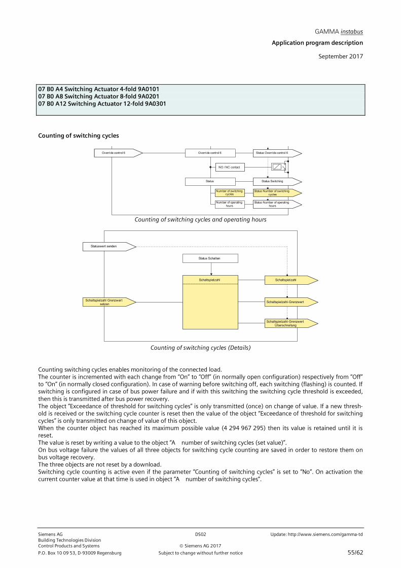
GAMMA instabus
Application program description
September 2017
07 B0 A4 Switching Actuator 4-fold 9A010107 B0 A8 Switching Actuator 8-fold 9A020107 B0 A12 Switching Actuator 12-fold 9A0301
Siemens AG DS02 Update: http://www.siemens.com/gamma-tdBuilding Technologies DivisionControl Products and Systems Siemens AG 2017
P.O. Box 10 09 53, D-93009 Regensburg Subject to change without further notice 55/62
Counting of switching cycles
Override control 6
Status Switching
Number of switchingcycles
Number of operatinghours
Override control 6 Status Override control 6
Status
Status Number of switchingcycles
Status Number of operatinghours
NO / NC contact
Counting of switching cycles and operating hours
Statuswert senden
Schaltspielzahl Grenzwertsetzen
Schaltspielzahl
Status Schalten
Schaltspielzahl
Schaltspielzahl-Grenzwert
Schaltspielzahl-GrenzwertÜberschreitung
Counting of switching cycles (Details)
Counting switching cycles enables monitoring of the connected load.The counter is incremented with each change from “On” to “Off” (in normally open configuration) respectively from “Off”to “On” (in normally closed configuration). In case of warning before switching off, each switching (flashing) is counted. Ifswitching is configured in case of bus power failure and if with this switching the switching cycle threshold is exceeded,then this is transmitted after bus power recovery.The object “Exceedance of threshold for switching cycles” is only transmitted (once) on change of value. If a new thresh-old is received or the switching cycle counter is reset then the value of the object “Exceedance of threshold for switchingcycles” is only transmitted on change of value of this object.When the counter object has reached its maximum possible value (4 294 967 295) then its value is retained until it isreset.The value is reset by writing a value to the object “A number of switching cycles (set value)”.On bus voltage failure the values of all three objects for switching cycle counting are saved in order to restore them onbus voltage recovery.The three objects are not reset by a download.Switching cycle counting is active even if the parameter “Counting of switching cycles” is set to “No”. On activation thecurrent counter value at that time is used in object “A number of switching cycles”.

GAMMA instabus
Application program description
September 2017
07 B0 A4 Switching Actuator 4-fold 9A010107 B0 A8 Switching Actuator 8-fold 9A020107 B0 A12 Switching Actuator 12-fold 9A0301
Update: http://www.siemens.com/gamma-td DS02 Siemens AGBuilding Technologies Division
Siemens AG 2017 Control Products and Systems
56/62 Subject to change without further notice P.O. Box 10 09 53, D-93009 Regensburg
Objects
These additional objects appear.
Obj Obejct name Funciton Type Flag
34 A Number of switching cycles Value 4 Byte CRT
This object is only available if the parameter "Counting of switching cycles" in the "A Functions, Objects" parameterwindow is set to "Enable".Via this object the number of switching cycles for the relevant output (1 switching cycle = switch output on and offagain) can be read at any time via the bus.If the parameter “Threshold monitoring” is set to “Enable” then a telegram is sent when the threshold is exceeded.
34 A Number of switching cycles Set Value 4 Byte CW
This object is only available if the parameter "Counting of switching cycles" in the "A Functions, Objects" parameterwindow is set to "Enable".Via this object the value for the switching cycle count for the relevant output can be set to an integer value between 1and 4 294 967 295 via the bus.
36 A Threshold for switching cycles Set Value 4 Byte CRW
This object is only available if the parameter "Threshold monitoring“ in the "Counting of switching cycles " parameterwindow is set in each case to "Enable".Via this object the threshold for the switching cycle count for the relevant output can be read and set as an integer valuebetween 1 and 4 294 967 295 via the bus.
37 A Exceedance of threshold forswitching cycles
ON / OFF 1 Bit CRWT
This object is only available if the parameter "Threshold monitoring“ in the "Counting of switching cycles " parameterwindow is set in each case to "Enable".Via this object the attaining or exceeding of the relevant switching cycle count threshold is reported via the bus respec-tively it can be queried whether the threshold is being exceeded.
Parameter „Functions, Objects“
Parameter Settings
Counting of switching cycles Disable;Enable
This parameter enables counting of switching cycles (i.e. how often an output has been switched on and off again) forthe corresponding output. If the parameter is set to "Enable", then the communication objects "A Number of switchingcycles" are added to this output.In addition the parameter window “Counting of switching cycles” appears.

GAMMA instabus
Application program description
September 2017
07 B0 A4 Switching Actuator 4-fold 9A010107 B0 A8 Switching Actuator 8-fold 9A020107 B0 A12 Switching Actuator 12-fold 9A0301
Siemens AG DS02 Update: http://www.siemens.com/gamma-tdBuilding Technologies DivisionControl Products and Systems Siemens AG 2017
P.O. Box 10 09 53, D-93009 Regensburg Subject to change without further notice 57/62
Parameter „Counting of switching cycles”
Parameter Settings
Send status on request Disable;Enable
This parameter determines whether the value of the object „A number of switching cycles“ shall be sent when arequest is received via object „Send status values“.
Send status on change of status Disable;Enable
This parameter determines whether the value of the object „A number of switching cycles“ shall automatically be senton a change of status.
Value change since last sent 1[0…4 294 967 295]
This parameter determines that the value of the object „A Number of switching cycles“ shall be sent onto the bus if thevalue of that object has changed by the selected value since the last transmission.
Note: The configurable value „0“ is interpreted as „1“.
Send status cyclically[hh:mm:ss]
00:00:00;[00:00:00…18:12:15]
This parameter determines the period for cyclically sending the status value.If the value is 00:00:00 then there is no cyclical sending.Threshold monitoring Disable;
EnableVia this parameter threshold monitoring is activated when “Enable” is selected.At the same time the associated status parameters and the parameter for input of the threshold for switching cyclesappear.See section “Status annunciation”, which describes the status parameters of the function “Status annunication”.
Additionally, these communication objects are added: “A Threshold for switching cycles” for reading and setting thethreshold and “A Exceedance of threshold for switching cycles” for annunciating reaching or exceeding the threshold.
Threshold for switching cycles 1000[0…4 294 967 295]
This parameter is visble when the parameter “Threshold montoring” is set to “Enable”.This parameter determines the threshold for the output.When the threshold is reached or exceeded then a telegram is sent via the object “A Exceedance of threshold forswitching cycles” depending on the sending conditions.
The parameters visible in the parameter window above the parameter “Threshold monitoring” refer to the object“A Number of switching cycles”.
The parameters visible in the parameter window below the parameter “Threshold monitoring” refer to the object„A Exceedance of threshold for switching cycles“. Configuration of the corresponding status parameters is described insection⇔ Status annunciation

GAMMA instabus
Application program description
September 2017
07 B0 A4 Switching Actuator 4-fold 9A010107 B0 A8 Switching Actuator 8-fold 9A020107 B0 A12 Switching Actuator 12-fold 9A0301
Update: http://www.siemens.com/gamma-td DS02 Siemens AGBuilding Technologies Division
Siemens AG 2017 Control Products and Systems
58/62 Subject to change without further notice P.O. Box 10 09 53, D-93009 Regensburg
Counting of operating hours
Override control 6
Status Switching
Number of switchingcycles
Number of operatinghours
Override control 6 Status Override control 6
Status
Status Number of switchingcycles
Status Number of operatinghours
NO / NC contact
Counting of switching cycles and operating hours
Statuswert senden
Betriebsstunden Grenzwertsetzen
Betriebsstunden
Status Schalten
Betriebsstunden
Betriebsstunden-Grenzwert
Betriebsstunden-GrenzwertÜberschreitung
Counting of operating hours (Details)
Counting operating hours enables monitoring of the connected load.The operating hours are counted while the switching status of the channel is “On”. Counting is active when the relayconfigured as normally open is closed respectively when the relay configured as normally closed is open. Only full se-conds are counted. The value of the object “Operating hours” is incremented by one when 3,600 seconds have beencounted.The object “Exceedance of threshold for operating hours” is only transmitted (once) on change of value. If a new thresh-old is received or the operating hours counter is reset then the value of the object “Exceedance of threshold for operatinghours” is only transmitted on change of value of this object. When the counter object has reached its maximum possiblevalue (4 294 967 295) then its value is retained until it is reset.The value is reset by writing a value to the object for the (current) switching cycle value.Operating hours cannot be counted on bus voltage failure.On bus voltage failure the values of all three objects for switching cycle counting are saved in order to restore them onbus voltage recovery.The three objects are not reset by a download.Counting operating hours is active even if the parameter “Counting of operating hours” is set to “Disable”.

GAMMA instabus
Application program description
September 2017
07 B0 A4 Switching Actuator 4-fold 9A010107 B0 A8 Switching Actuator 8-fold 9A020107 B0 A12 Switching Actuator 12-fold 9A0301
Siemens AG DS02 Update: http://www.siemens.com/gamma-tdBuilding Technologies DivisionControl Products and Systems Siemens AG 2017
P.O. Box 10 09 53, D-93009 Regensburg Subject to change without further notice 59/62
Objects
These additional objects appear.
Obj Object name Function Type Flag
38 A Operating hours Value 4 Byte CRT
This object is visible if the parameter "Counting of operating hours" in the “A Functions, Objects“ parameter window isset to "Enable" and the in the parameter window “Operating hours”the parameter "Counting of operating hours“ is setto “hours”.Via this object the current number of operating hours for the relevant output (i.e. how many hours the output was ON)can be queried via the bus at any time.
39 A Operating hours Value (in se-conds)
4 Byte CRT
This object is visible if the parameter "Counting of operating hours" in the “A Functions, Objects“ parameter window isset to "Enable" and the in the parameter window “Operating hours”the parameter "Counting of operating hours“ is setto “seconds”.
Via this object the current number of operating hours for the relevant output (i.e. how many hours the output was ON)can be queried via the bus at any time.
40 A Operating hours Set Value 4 Byte CRW
This object is visible if the parameter "Counting of operating hours" in the “A Functions, Objects“ parameter window isset to "Enable".Via this object the value for the operating hours count for the relevant output can be set to an integer value between 1and 4 294 967 295 via the bus. The value is transmitted as hours.This object is always set in hours, independent of the configured setting for the annunciation of the operating hours inseconds or hours via objects 38 or 39.
41 A Threshold for operating hours Set Value 4 Byte CRW
This object is only available if the parameter "Counting of operating hours" in the “A Functions, Objects“ parameterwindow is set to "Enable" and the parameter “Threshold monitoring” in the parameter window “Operating hours” is setto “Enable”..Via this object the threshold for the operating hours count for the relevant output is sent as an integer value between 1and 4 294 967 295 to the switching actuator via the bus.The value is transmitted as hours.
42 A Exceedance of threshold foroperating hours
ON / OFF 1 Bit CRWT
This object is only available if the parameter "Counting of operating hours" in the “A Functions, Objects“ parameterwindow is set to "Enable" and the parameter “Threshold monitoring” in the parameter window “Operating hours” is setto “Enable”..Via this object the attaining or exceeding of the relevant operating hours threshold is reported via the bus respectively itcan be queried whether the threshold is being exceeded.

GAMMA instabus
Application program description
September 2017
07 B0 A4 Switching Actuator 4-fold 9A010107 B0 A8 Switching Actuator 8-fold 9A020107 B0 A12 Switching Actuator 12-fold 9A0301
Update: http://www.siemens.com/gamma-td DS02 Siemens AGBuilding Technologies Division
Siemens AG 2017 Control Products and Systems
60/62 Subject to change without further notice P.O. Box 10 09 53, D-93009 Regensburg
Parameter „Functions, Objects“
Parameter Settings
Counting of operating hours Disable;Enable
This parameter enables counting of operating hours (i.e. for how many hours the output was switched on) for thecorresponding output. If the parameter is set to "Enable", then only the communication objects ”A Operating hours"are added to this output.Additionally, the parameter window for operating hours appears.
Parameter „Operating hours“
Parameter Settings
Counting of operating hours in hours;seconds
This parameter determines if the operating hours are counted for the output in hours or seconds.Send status on request Disable;
EnableThis parameter determines whether the value of the object „A Operating hours“ shall be sent when a request isreceived via object „Send status values“.
Send status on change of status Disable;Enable
This parameter determines whether the value of the object „A Operating hours“ shall automatically be sent on achange of status.
Value change since last sent 1[0…4 294 967 295]
This parameter determines that the value of the object „A Operating hours“ shall be sent onto the bus if the value ofthat object has changed by the selected value since the last transmission.
Send status cyclically[hh:mm:ss]
00:00:00;[00:00:00…18:12:15]
This parameter determines the period for cyclically sending the status value.
If the value is 00:00:00 then there is no cyclical sending.Threshold monitoring Disable;
EnableVia this parameter threshold monitoring is activated when “Enable” is selected.
At the same time the associated status parameters and the parameter for input of the threshold for operating hoursappear.See section “Status annunciation”, which describes the status parameters of the function “Status annunication”.Additionally, these communication objects are added: “A Threshold for operating hours” for reading and setting thethreshold and “A Exceedance of threshold for operating hours” for annunciating reaching or exceeding the threshold.

GAMMA instabus
Application program description
September 2017
07 B0 A4 Switching Actuator 4-fold 9A010107 B0 A8 Switching Actuator 8-fold 9A020107 B0 A12 Switching Actuator 12-fold 9A0301
Siemens AG DS02 Update: http://www.siemens.com/gamma-tdBuilding Technologies DivisionControl Products and Systems Siemens AG 2017
P.O. Box 10 09 53, D-93009 Regensburg Subject to change without further notice 61/62
Parameter Settings
Threshold for operating hours 1000[0…4 294 967 295]
This parameter is visble when the parameter “Threshold montoring” is set to “Enable”.This parameter determines the threshold for the output.When the threshold is reached or exceeded then a telegram is sent via the object “A Exceedance of threshold foroperating hours” depending on the sending conditions.
The parameters visible in the parameter window above the parameter “Threshold monitoring” refer to the object“A Operating hours”.
The parameters visible in the parameter window below the parameter “Threshold monitoring” refer to the object„A Exceedance of threshold for operating hours“. Configuration of the corresponding status parameters is described insection⇔ Status annunciation

GAMMA instabus
Application program description
September 2017
07 B0 A4 Switching Actuator 4-fold 9A010107 B0 A8 Switching Actuator 8-fold 9A020107 B0 A12 Switching Actuator 12-fold 9A0301
Update: http://www.siemens.com/gamma-td DS02 Siemens AGBuilding Technologies Division
Siemens AG 2017 Control Products and Systems
62/62 Subject to change without further notice P.O. Box 10 09 53, D-93009 Regensburg
Space for notes