use saltwater as an rf radiator and ‘go with the flow’...
TRANSCRIPT

Use Saltwater as an RF Radiator and ‘Go with the Flow’ on 2 Meters
Glub, Glub, Glub:The Amazing Aqueous Antenna
BY VERNON R. HARRIS,* W7GGM
WWater for a 2-meter antenna’s radiating element. Now,there’s a concept.
It can be done. I did it.Conventional antennas are constructed using wire, metal
pipes, conduit, or similar materials. The Aqueous Antennajumps beyond these standard materials and is constructedusing saltwater for the radiating element, Photo A.
I’ve never heard of this being attempted, let alone accom-plished. But the Aqueous Antenna, as I’ve named it, is basi-cally constructed of water or a water-based liquid instead ofthe standard conductors. The radiating elements are madeof an aqueous solution and if constructed properly can be avery good radiator.
In the past, antennas were constructed using a piece offeed line — usually coax — that was laid out and connect-ed to some sort of wire antenna. The antenna added to theend of the coax could be one of many different designs toprovide the desired performance feature.
The simplest form was usually a dipole constructed suchthat there was an egg insulator in the center of the antennathat separated the two poles that made up the dipole anten-na. The ends of each pole usually had some sort of insula-tor to electrically isolate the antenna ends from the environ-ment and allow the antenna to perform as expected.
For my research, two versions of the Aqueous Antennawere built and tested — a vertical and a dipole.
Tools and Parts Required for W7GGM AqueousAntennas
• A length of coax cable — RG-58, for example• Tape measure• Sharp knife• Pair of scissors• An assortment of cable ties• Plastic tubing, clear, flexible — 3/8-inch inside
diameter• Rubber stoppers to plug the ends of the plastic
tubing to hold in the water — 5/16-inch or smaller• A soldering iron or gun, solder, and solder flux• A physical support frame, such as yard sticks for
mounting the antennas• Electronics hand tools for general use
The 2-Meter Aqueous Vertical GroundplaneFirst we need to prepare the materials to make the Aqueous
Vertical Groundplane, Photo B.
Provide a length of coax cable, either RG-58 or similar, torun from the transceiver outside the radio shack to wherethe antenna will be located.
The antenna-end of the coax will be opened up so that thetwo conductors have about 2 inches exposed for the elec-trical connections.
The contact points chosen for the aqueous antennas were1-inch-long weather stripping nails and a small alligator clip,Photo C. The two coax conductors were prepared by remov-ing the insulation and exposing enough wire on the centerconductor to allow a loop to be formed around the nail nextto the nail head.
The loop was pressed into place using small pliers andthen a small amount of solder flux was added to the loop. Asoldering gun was used to heat the joint and the flux allowedthe solder to flow evenly.* Email <[email protected]>
Photo A. The W7GGM Aqueous Dipole antenna’s performance on 2-meter FM exceeded its designer’sexpectation — as did the Aqueous Vertical. It is possible to generate a fine VHF signal using a saltwater solution for an RF radiator, as this V dipole shows.
118 • CQ plus • September 2014 Visit Our Web Site

Once the soldering joint was com-plete, it was cleaned using rubbing alco-hol to remove residue. For the braidconductor, a small alligator clip wasinstalled to allow it to be connected to aground-plane radial system.
The sharp end of the center conduc-tor nail, Photo C, was held using nee-dle-nose pliers and the sharp end of thenail was forced through the large end ofone of the rubber stoppers.
The nail was inserted as far as possi-ble so that its head rested snug againstthe rubber stopper. This allowed about3/8-inch of the nail to be exposedthrough the center of the rubber plug.The center conductor rubber stopper
was then slid inside the lower end of theplastic tubing until snuggly in place. Thisarrangement seals the end of the plas-tic tubing so that water cannot leak outand to provide an electrical contact withthe water inside the clear tubing. Thebraid of the coax was fitted with an alli-gator clip so it could later be clipped tothe ground radial system.
Next, the clear plastic tubing wasstretched out along a wooden yardstick,Photo D. The tubing was started justbelow the zero mark of the yardstick.The plastic tubing along the yardstickwas then attached using plastic tiewraps to snuggly hold the tubing againstthe yardstick.
Additional tie points could be addedas desired, to secure the yardstick andplastic tubing together. At the far end ofthe yardstick the plastic tubing extend-ed just beyond the yardstick end.
A rubber stopper was placed in the farend of the plastic tubing. The spacebetween the two rubber stoppers waslater filled with saltwater to form the ver-tical radiating element.
Next, the ground plane wires wereformed and added to the vertical anten-na. For this antenna, four ground planewires were selected from stiff copperwire stock. Each radial was formed to alength of 22 inches. This was done bycutting two stiff wires 45 inches inlength, crossing them at the centers,and twisting them about each other toform a tight joint.
This joint was then soldered. The radi-als were then evenly separated and laidout flat on a card table. The vertical partof the antenna was then suspendeddirectly above the radial layout and thecoax braid lead was alligator clipped tothe radial solder joint. The alligator clipwas used to temporarily provide thisrequired electrical connection for test-ing with the idea that later the shieldconductor would be soldered to the radi-al joint.
Next, the water solution was added tothe plastic tubing — a salt-saturatedbrine solution which was quicklyobtained by simply dipping a glass-fullof the saltwater found in my water soft-ener salt holding tank. This solution isa salt-saturated water mixture. Thesame solution can be obtained by tak-ing a glass of tap water and adding table
Photo B. With the 2-meter vertical ground plane, radials 22-inches long are positioned at the base of the radiating element — saltwater solution in a plastic tube.
Photo C. A 1-inch-long nail is pushed through a rubberstopper to make contact between the feed line’s inner conductor and the saltwater radiator. The braid of the oax is attached to the radials with an alligator clip.
Photo D. The vertical plastic tubing holding the saltwatersolution is secured to the yardstick using plastic ties.
www.cq-amateur-radio.com September 2014 • CQ plus • 119
salt while continuously stirring the solu-tion. Keep adding salt a spoon at a timeuntil the water will not accept more saltand additional salt simply falls to the bot-tom of the glass.
Adding the Salt Solution to the Antenna
The rubber stopper at the high end ofthe vertical radiator is then removed.Using a small turkey baster or infantnasal aspirator, the salt solution is slow-ly added to the top of the plastic tubing.
It must be added slowly so it dribblesdown the inside of the tubing. If it isadded quickly, solution droplets will fillthe plastic tubing in the form of a smallglob and plug the plastic tubing — notallowing more solution to be added. Byadding the solution slowly the air withinthe tubing can escape as more solutionis added and allow the tubing to be filled.
The salt solution was added until itwas close to the top of the plastic tube.The rubber stopper can then be placedin the top end of the tube or it can beleft out until all the antenna testing iscompleted.
Testing the Aqueous VerticalAntenna
The first test to be made was a checkon the SWR. I selected a frequency inthe 2-meter band. With almost 36 inch-es of salt solution in the plastic tubingthe SWR was up around 3.0 or perhaps
a bit higher. Note the SWR reading andthe height of the water solution.
Lean the vertical tubing to one side toremove a bit of the salt solution. I wouldrecommend removing about 2 inches ofsolution and make another SWR test.When removing some of solution fromthe plastic tubing, do it carefullybecause a small amount of solutionremoval could result in an unexpectedsolution height change. Remove just afew drops at a time.
The markers on the yardstick will pro-vide reference marks to easily showhow much solution is in the plastic tube.If too much solution is removed, simplyadd a few drops back to the tube to getthe desired solution height.
Check the SWR after each 2-inch low-ering of the salt solution. After eachsolution removal, the SWR should showa continued downward trend.
When the SWR gets down to a rea-sonable value, it can be further loweredby making mini-adjustments to the saltsolution height. I found that when doingfinal solution height adjustments, thebest SWR values could be obtained bychanging the solution by only two orthree drops at a time. By being careful,I was able to obtain an SWR value of 1.6.
The Aqueous Vertical:Conclusions and Thoughts
The Aqueous Vertical is a workableantenna with the final SWR of 1.5 and1.7. It appears that for a given frequen-
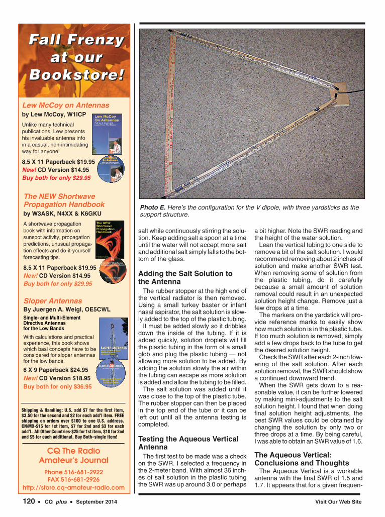
Photo E. Here’s the configuration for the V dipole, with three yardsticks as thesupport structure.
120 • CQ plus • September 2014 Visit Our Web Site
CQ The Radio Amateur's Journal
Phone 516-681-2922FAX 516-681-2926
http://store.cq-amateur-radio.com
Shipping & Handling: U.S. add $7 for the first item,$3.50 for the second and $2 for each add’l item. FREEshipping on orders over $100 to one U.S. address.CN/MX-$15 for 1st item, $7 for 2nd and $3 for eachadd’l. All Other Countries-$25 for 1st item, $10 for 2ndand $5 for each additional. Buy Both=single item!
The NEW ShortwavePropagation Handbook by W3ASK, N4XX & K6GKU
A shortwave propagationbook with information onsunspot activity, propagationpredictions, unusual propaga-tion effects and do-it-yourselfforecasting tips.
8.5 X 11 Paperback $19.95 New! CD Version $14.95Buy both for only $29.95
Lew McCoy on Antennasby Lew McCoy, W1ICP
Unlike many technical publications, Lew presentshis invaluable antenna infoin a casual, non-intimidatingway for anyone!
8.5 X 11 Paperback $19.95 New! CD Version $14.95Buy both for only $29.95
Sloper AntennasBy Juergen A. Weigl, OE5CWLSingle- and Multi-ElementDirective Antennas for the Low Bands
With calculations and practicalexperience, this book showswhich basi concepts have to beconsidered for sloper antennasfor the low bands.
6 X 9 Paperback $24.95New! CD Version $18.95Buy both for only $36.95
FFFFaaaallll llll FFFFrrrreeeennnnzzzzyyyyaaaatttt oooouuuurrrr
BBBBooooooookkkkssssttttoooorrrreeee!!!!

cy, the antenna formula is not valid when trying to calculatethe length of a quarter-wave whip made of saltwater.
The final length or column height was 21-1/2 inches insteadof usual 19-1/4 inches if standard copper wire had been usedfor the whip. This says that the tuned aqueous antenna waslengthened by 21.5/19.25, or about 12 percent longer than astandard quarter-wave, 2-meter whip antenna.
The Aqueous Vertical’s performance exceeded expecta-tions. Checking the SWR at various frequencies on 2 metersindicated readings did not change much across the band.The tuning and operation seems to be quite broad comparedto most vertical antennas.
It was used to work through a local repeater. Getting in wasno problem.
Later, the antenna was used to communicate during a reg-ular emergency net operation. Operators out at the edge ofwhere my J-Pole normally performs well could tell no differ-ence between my J-Pole signal and the aqueous antennasignal.
My received signals seem to be just as strong as whenusing the J-Pole antenna. The emergency net on this occa-sion was not using the local repeater but rather was operat-ing FM simplex.
The purpose of building the aqueous or water antenna wasnot intended to provide another antenna choice for 2 meters.The purpose was to build and confirm the operation of a newconcept in antenna theory and design.
I had been told by some that such an antenna could not bebuilt simply because the idea was not in the antenna theorybooks. To use water instead of standard conductors was sofar outside the box, the idea might never work. I too believedthis to some extent and was very excited to see that it actu-ally was a good performer.
The Aqueous Dipole AntennaWhen building the Aqueous Dipole Antenna, Photo E, the
same instructions apply when preparing for assembly.Provide the coax feed line for the dipole antenna. Prepareboth coax conductors with electrical contacts using the nailsand solder just as with the vertical antenna. Push the point-ed ends of the contact nails through the large ends of tworubber stoppers.
Lay out two pieces of the 3/8-inch plastic tubing and secure them to two wooden yardsticks using plastic tie wraps,Photo F.
For this antenna, each radiating element will be positionedsuch that the arms are pointing upward at about 45 degreesinstead of straight out.
When finally laid out, the antenna will resemble a V anten-na. This is necessary to ensure that the salt solution alwaysremains in contact with the electrical contact nails in the lowerparts of the antenna. Also, with the arms being orientedupward the height of the solution columns is much moredefined and easier to read.
The angle for the V will be obtained by laying out the twoyardsticks on a table at about a 45-degree angle with the con-tact, or lower ends, almost touching. Now lay a third yard-stick across the tops of the two radiating elements (Photo E).Adjust the spacing such that the third yardstick crosses thetwo antenna arms at the very ends of the elements. With thethird yardstick as spacing and support, drill small holesthrough the two yard stick crossings and secure the twocrossings with plastic tie wraps. This is where each of theAqueous Dipole’s elements will be secured to the structureas well, Photo G.
Photo F. Here’s a close-up of the completed feed line-antenna connection. A rectangular piece of wood isthe support point for the base of the V. After all the connections are checked and secure, the saltwater solution is added to each side of the dipole, and SWR testing begins.
Photo G. The Aqueous Dipole’s elements secured to the structure.
www.cq-amateur-radio.com September 2014 • CQ plus • 121

Three tie wraps at each crossing hold the antenna supportstogether.
At the lower ends of the yardsticks, set them about 1-inchapart and attach the ends to a small, wood block using plas-tic tie wraps. Mine measures about 5-by-8 inches.
See in Photo A that I then attached the antenna and woodsupport block to the top of a 10-foot wood pole using largetie wraps. The coax ran down the wood support pole and wassecured using plastic tie wraps.
The coax connector nails and rubber stoppers were theninserted into the bottoms of the two plastic water tubes. At thetop of the plastic tubes the same type of saltwater used in thevertical was slowly added to each tube. When mostly full, theupper tubes were provided with two more rubber stoppers.
The rubber stoppers can be put in place or left out duringthe antenna testing. The antenna was then ready for testing.
Testing the Aqueous DipoleThe same frequency used for testing the aqueous vertical
antenna was chosen to test the dipole. With the radiatingtubes mostly full, the SWR was found to be over 3.0. Thesame procedure for changing the solution height was fol-lowed as was done for the vertical antenna.
By tilting each side of the antenna over, a little bit of saltsolution was allowed to drain out of the tube. Both ends ofthe dipole were adjusted to keep the height of the salt solu-tion the same for both sides.
Again, with the first 2 inches of solution removed, the SWRshowed a slight decrease. When the SWR was reduced downto a reasonable level, the solution height change was reducedto 1 inch for each SWR test.
Ultimately, the SWR bottomed out and started back upagain. The next steps were to change the solution height by
only 1/2-inch until I could see another dip. Then the antennasolution heights were changed by adding or subtracting thesolution by only 2 or 3 drops at a time. The SWR finally bot-tomed out at 1.8.
Operational testing of the Aqueous Dipole was similar totesting the Aqueous Vertical antenna. The Aqueous Dipolecould easily hit the local repeater. Several hams were workedin this mode and the antenna worked fine.
The dipole was later tested using the same emergency netcommunications. The signal reports were again that the sig-nal was just as strong and good-sounding as with my J-Pole.
As might be expected, when talking to operators off the endof the dipole the signal was not as strong as when the oper-ators were broadside to the dipole. This makes reasonablesense since there is less of a signal to work with off the endsof a dipole antenna. In this situation, the J-pole performancewas superior.
The Aqueous Dipole: Conclusions andThoughts
The Aqueous Dipole Antenna seemed to be a bit easier tobuild. However, if proper space is available for the ground-plane radials, the vertical antenna may be the best choice,since it is omni-directional.
Both antennas were designed and built as “proof of con-cept” projects. Neither was intended to be an antenna toreplace an existing design or provide some wondrousimprovement in performance.
Rather, these two antenna projects were intended to pos-sibly change the way we think about antennas and to get usto “think outside the box” concerning antenna theory and whatmight be possible using new ideas.
My hope is to see additional articles published by hams withan entrepreneurship drive; picking up the thinking and ele-vating it to new levels of activity. Projects such as mine canbe a seedbed for additional thinking and advanced projectsby and for radio amateurs.
General ThoughtsThings that might be considered when attempting improve-
ments to the aqueous antennas:
• Vary the diameter of the plastic saltwater tubes.• Vary the concentration of the salt solution. Also, other
type salts could be experimented with to possibly improve the performance.
• Experiment by using automobile anti-freeze or RV plumbing anti-freeze, in place of tap water, to lower thefreezing point of the solution.
• Experiment with different selections for the coax con-nectors instead of the 1-inch nails. The performance might be enhanced by using longer contacts to providemore contact surface area with the salt solution. The type of material the contact is made of could also be changed. Stainless steel contacts could provide less of a corrosive potential for the connectors.
(ABOUT THE WRITER: Vernon R. Harris, W7GGM, studiedelectrical engineering at the University of Oklahoma. He hasworked for the Department of Defense, U.S. Air Force, and theFederal Aviation Administration in varied technical capacities.He is an established author, having written everything from tech-nical manuals to books of humor, sci-fi, general fiction, and non-fiction. Mostly retired, Harris is owner of Bear Mountain Scientific<http://www.BearMountainScientific.com>. – KI6SN.)
122 • CQ plus • September 2014 Visit Our Web Site
TriQuint Introduces New AmplifierRFMW, Ltd. has added the TQC9305, a 0.7- to 3.6-GHz
digitally-controlled, Variable Gain Amplifier (DVGA) fromTriQuint. The TQC9305features a shutdown pinfunction for TDD applica-tions and offers 40-dBmOIP3 for linear operation.
The integrated attenua-tor has 31-dB range in 1-dB steps. The TQC9305comes internally matched,eliminating the need forexternal matching compo-nents. Suited for both TDDand FDD systems, the TQC9305 is used in tower-mountedamplifiers, repeaters, small cells and defense related com-munication systems.
This TriQuint DVGA operates on a 5-volt supply drawing130 mA and comes in a 5x5 mm MSL3 package. For moreinformation contact: RFMW, Ltd., 188 Martinvale Lane, San Jose, CA 95119. Phone: (408)414-1450. Email:<[email protected]>.
Note: “What’s New” is not a product review and does not constitutea product endorsement by CQ. Information is primarily provided bymanufacturers/vendors and has not necessarily been independentlyverified.
what’s new