use vivado to build an embedded system - masarykova … · use vivado to build an embedded system...
TRANSCRIPT
Lab Workbook Use Vivado to build an Embedded System
www.xilinx.com/university ZedBoard 1-1 [email protected] © copyright 2013 Xilinx
Use Vivado to build an Embedded System
Introduction
This lab guides you through the process of using Vivado to create a simple ARM Cortex-A9 based processor design targeting the ZedBoard development board. You will use Vivado to create the hardware system and SDK (Software Development Kit) to create an example application to verify the hardware functionality.
Objectives
After completing this lab, you will be able to: Create a Vivado project for a Zynq system Use the IP Integrator to create a hardware system Use SDK to create a standard memory test project Run the test application on the board
Procedure
This lab is separated into steps that consist of general overview statements that provide information on the detailed instructions that follow. Follow these detailed instructions to progress through the lab.
This lab comprises 5 primary steps: You will create a top-level project using Vivado, create the processor system using the Vivado IP Integrator, generate the top-level HDL and export the design to SDK, create a Memory Test application in SDK, and finally, test in hardware.
Design Description
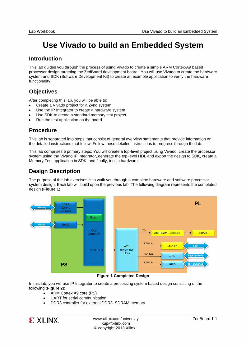
The purpose of the lab exercises is to walk you through a complete hardware and software processor system design. Each lab will build upon the previous lab. The following diagram represents the completed design (Figure 1).
Figure 1 Completed Design
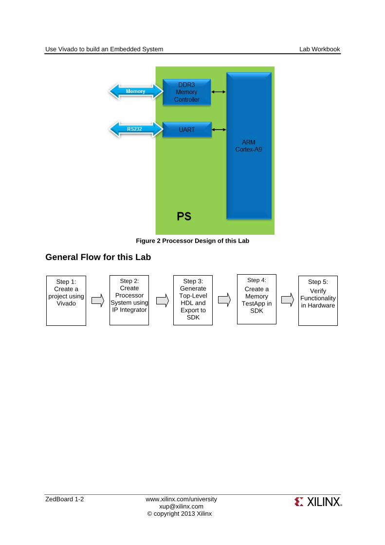
In this lab, you will use IP Integrator to create a processing system based design consisting of the following (Figure 2):
ARM Cortex A9 core (PS) UART for serial communication DDR3 controller for external DDR3_SDRAM memory
Use Vivado to build an Embedded System Lab Workbook
ZedBoard 1-2 www.xilinx.com/university [email protected] © copyright 2013 Xilinx
Figure 2 Processor Design of this Lab
General Flow for this Lab
Step 1: Create a
project using Vivado
Step 2: Create
Processor System using IP Integrator
Step 3: Generate Top-Level HDL and Export to
SDK
Step 4:
Create a Memory
TestApp in SDK
Step 5:
Verify Functionality in Hardware
Lab Workbook Use Vivado to build an Embedded System
www.xilinx.com/university ZedBoard 1-3 [email protected] © copyright 2013 Xilinx
Create a Vivado Project Step 1
1-1. Launch Vivado and create an empty project targeting the Zedboard (having xc7z020clg484-1 device) and using the VHDL language.
1-1-1. Open Vivado by selecting Start > All Programs > Xilinx Design Tools > Vivado 2013.3 > Vivado 2013.3
1-1-2. Click Create New Project to start the wizard. You will see the Create a New Vivado Project dialog box. Click Next.
1-1-3. Click the Browse button of the Project Location field of the New Project form, browse to c:\xup\embedded\labs, and click Select.
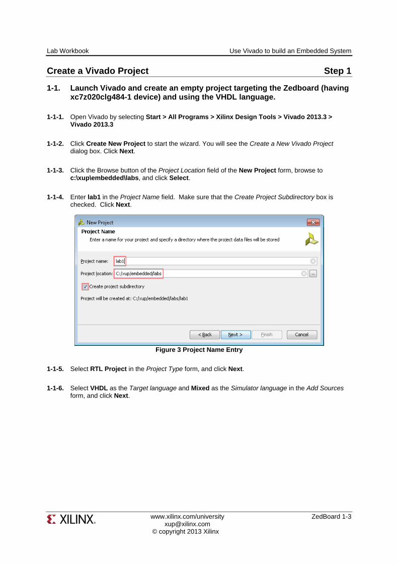
1-1-4. Enter lab1 in the Project Name field. Make sure that the Create Project Subdirectory box is checked. Click Next.
Figure 3 Project Name Entry
1-1-5. Select RTL Project in the Project Type form, and click Next.
1-1-6. Select VHDL as the Target language and Mixed as the Simulator language in the Add Sources form, and click Next.

Use Vivado to build an Embedded System Lab Workbook
ZedBoard 1-4 www.xilinx.com/university [email protected] © copyright 2013 Xilinx
Figure 4 Add sources to new project
1-1-7. Click Next two more times to skip Adding Existing IP and Add Constraints
1-1-8. In the Default Part form, select Boards, and select Zedboard Zynq Evaluation and Development Kit. Click Next.
Figure 5 Boards and Parts Selection
1-1-9. Check the Project Summary and click Finish to create an empty Vivado project.
Lab Workbook Use Vivado to build an Embedded System
www.xilinx.com/university ZedBoard 1-5 [email protected] © copyright 2013 Xilinx
Creating the System Using the IP Integrator Step 2
2-1. Use the IP Integrator to create a new Block Design, and generate the ARM Cortex-A9 processor based hardware system, targeting the ZedBoard.
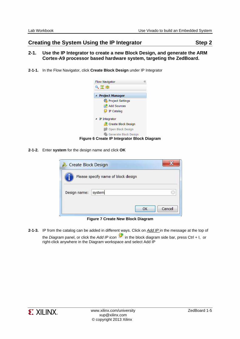
2-1-1. In the Flow Navigator, click Create Block Design under IP Integrator
Figure 6 Create IP Integrator Block Diagram
2-1-2. Enter system for the design name and click OK
Figure 7 Create New Block Diagram
2-1-3. IP from the catalog can be added in different ways. Click on Add IP in the message at the top of
the Diagram panel, or click the Add IP icon in the block diagram side bar, press Ctrl + I, or right-click anywhere in the Diagram workspace and select Add IP

Use Vivado to build an Embedded System Lab Workbook
ZedBoard 1-6 www.xilinx.com/university [email protected] © copyright 2013 Xilinx
Figure 8 Add IP to Block Diagram
2-1-4. Once the IP Catalog is open, type “z” into the Search bar, find and double click on ZYNQ7 Processing System entry, or click on the entry and hit the Enter key to add it to the design.
Figure 9 Add Zynq block to the design
2-1-5. Notice the message at the top of the Diagram window that Designer Assistance available. Click on Run Block Automation and select /processing_system7_1

Lab Workbook Use Vivado to build an Embedded System
www.xilinx.com/university ZedBoard 1-7 [email protected] © copyright 2013 Xilinx
Figure 10 Designer Assistance message
2-1-6. Click OK when prompted to run automation
Figure 11 Run Block Automation
Once Block Automation has been complete, notice that ports have been automatically added for the DDR and Fixed IO, and some additional ports are now visible. A default configuration for the Zynq has been applied which will now be modified.
Figure 12 Zynq Block with DDR and Fixed IO ports
2-1-7. In the block diagram, double click on the Zynq block to open the Customization window for the Zynq processing system.
2-1-8. A block diagram of the Zynq should now be open, showing various configurable blocks of the Processing System.
At this stage, the designer can click on various configurable blocks (highlighted in green) and change the system configuration.
Use Vivado to build an Embedded System Lab Workbook
ZedBoard 1-8 www.xilinx.com/university [email protected] © copyright 2013 Xilinx
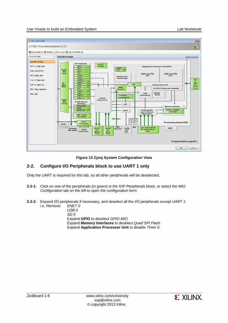
Figure 13 Zynq System Configuration View
2-2. Configure I/O Peripherals block to use UART 1 only
Only the UART is required for this lab, so all other peripherals will be deselected.
2-2-1. Click on one of the peripherals (in green) in the IOP Peripherals block, or select the MIO Configuration tab on the left to open the configuration form
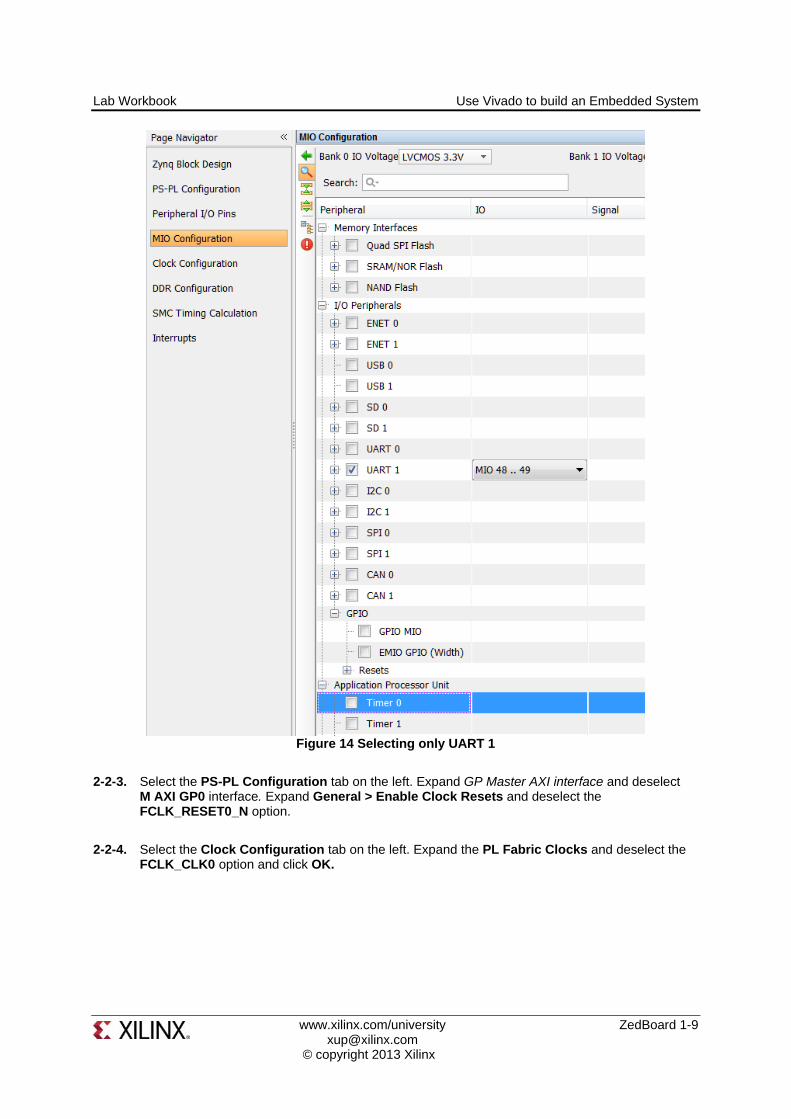
2-2-2. Expand I/O peripherals if necessary, and deselect all the I/O peripherals except UART 1. i.e. Remove: ENET 0
USB 0 SD 0 Expand GPIO to deselect GPIO MIO Expand Memory Interfaces to deselect Quad SPI Flash Expand Application Processor Unit to disable Timer 0.
Lab Workbook Use Vivado to build an Embedded System
www.xilinx.com/university ZedBoard 1-9 [email protected] © copyright 2013 Xilinx
Figure 14 Selecting only UART 1
2-2-3. Select the PS-PL Configuration tab on the left. Expand GP Master AXI interface and deselect M AXI GP0 interface. Expand General > Enable Clock Resets and deselect the FCLK_RESET0_N option.
2-2-4. Select the Clock Configuration tab on the left. Expand the PL Fabric Clocks and deselect the FCLK_CLK0 option and click OK.
Use Vivado to build an Embedded System Lab Workbook
ZedBoard 1-10 www.xilinx.com/university [email protected] © copyright 2013 Xilinx
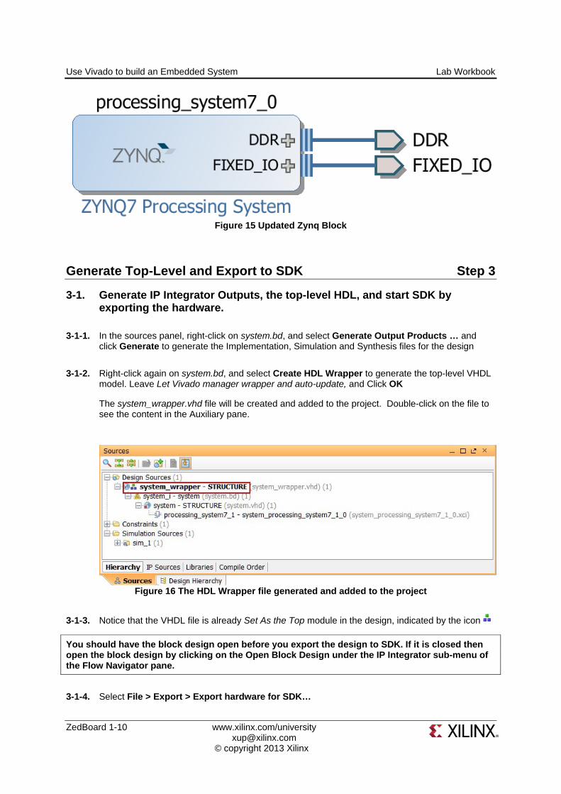
Figure 15 Updated Zynq Block
Generate Top-Level and Export to SDK Step 3
3-1. Generate IP Integrator Outputs, the top-level HDL, and start SDK by exporting the hardware.
3-1-1. In the sources panel, right-click on system.bd, and select Generate Output Products … and click Generate to generate the Implementation, Simulation and Synthesis files for the design
3-1-2. Right-click again on system.bd, and select Create HDL Wrapper to generate the top-level VHDL model. Leave Let Vivado manager wrapper and auto-update, and Click OK
The system_wrapper.vhd file will be created and added to the project. Double-click on the file to see the content in the Auxiliary pane.
Figure 16 The HDL Wrapper file generated and added to the project
3-1-3. Notice that the VHDL file is already Set As the Top module in the design, indicated by the icon
You should have the block design open before you export the design to SDK. If it is closed then open the block design by clicking on the Open Block Design under the IP Integrator sub-menu of the Flow Navigator pane.
3-1-4. Select File > Export > Export hardware for SDK…
Lab Workbook Use Vivado to build an Embedded System
www.xilinx.com/university ZedBoard 1-11 [email protected] © copyright 2013 Xilinx
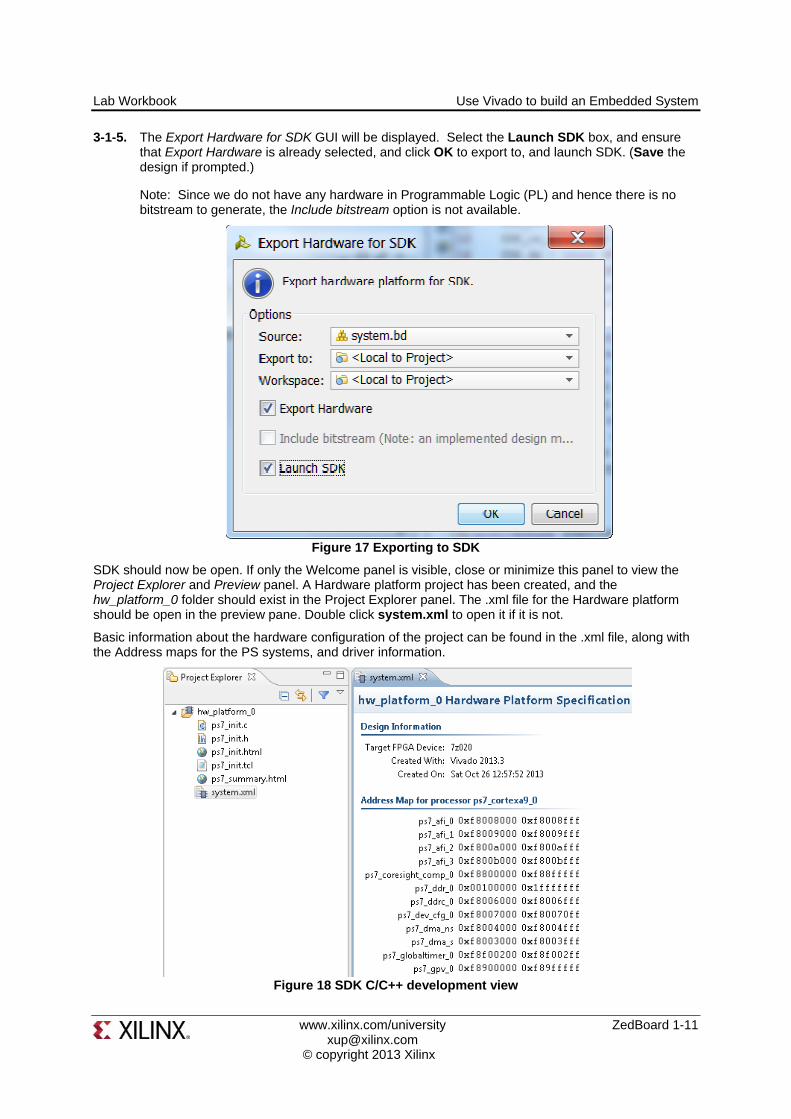
3-1-5. The Export Hardware for SDK GUI will be displayed. Select the Launch SDK box, and ensure that Export Hardware is already selected, and click OK to export to, and launch SDK. (Save the design if prompted.)
Note: Since we do not have any hardware in Programmable Logic (PL) and hence there is no bitstream to generate, the Include bitstream option is not available.
Figure 17 Exporting to SDK
SDK should now be open. If only the Welcome panel is visible, close or minimize this panel to view the Project Explorer and Preview panel. A Hardware platform project has been created, and the hw_platform_0 folder should exist in the Project Explorer panel. The .xml file for the Hardware platform should be open in the preview pane. Double click system.xml to open it if it is not.
Basic information about the hardware configuration of the project can be found in the .xml file, along with the Address maps for the PS systems, and driver information.
Figure 18 SDK C/C++ development view
Use Vivado to build an Embedded System Lab Workbook
ZedBoard 1-12 www.xilinx.com/university [email protected] © copyright 2013 Xilinx
Generate Memory TestApp in SDK Step 4
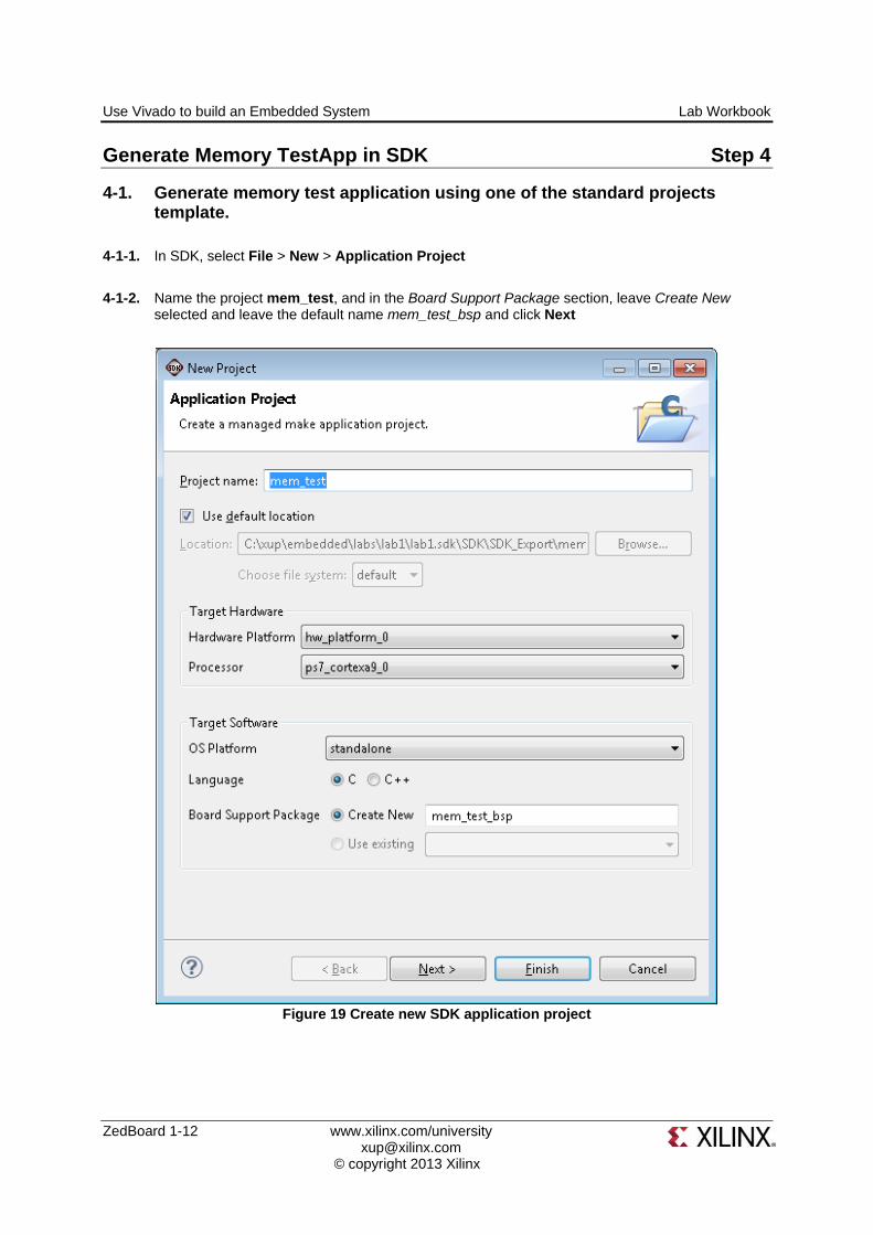
4-1. Generate memory test application using one of the standard projects template.
4-1-1. In SDK, select File > New > Application Project
4-1-2. Name the project mem_test, and in the Board Support Package section, leave Create New selected and leave the default name mem_test_bsp and click Next
Figure 19 Create new SDK application project
Lab Workbook Use Vivado to build an Embedded System
www.xilinx.com/university ZedBoard 1-13 [email protected] © copyright 2013 Xilinx
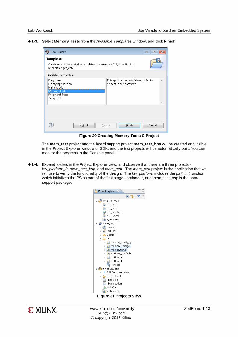
4-1-3. Select Memory Tests from the Available Templates window, and click Finish.
Figure 20 Creating Memory Tests C Project
The mem_test project and the board support project mem_test_bps will be created and visible in the Project Explorer window of SDK, and the two projects will be automatically built. You can monitor the progress in the Console panel.
4-1-4. Expand folders in the Project Explorer view, and observe that there are three projects - hw_platform_0, mem_test_bsp, and mem_test. The mem_test project is the application that we will use to verify the functionality of the design. The hw_platform includes the ps7_init function which initializes the PS as part of the first stage bootloader, and mem_test_bsp is the board support package.
Figure 21 Projects View
Use Vivado to build an Embedded System Lab Workbook
ZedBoard 1-14 www.xilinx.com/university [email protected] © copyright 2013 Xilinx
4-1-5. Open the memorytest.c file in the mem_test project (under src), and examine the contents. This file calls the functions to test the memory.
Test in Hardware Step 5
5-1. Connect and power up the board. Establish the serial communication using SDK’s Terminal tab.
5-1-1. Connect one micro-usb cable between the PC and the JTAG port of the board, another micro-usb cable between the PC and the UART port of the board, and power up the ZedBoard.
5-1-2. Select the tab. If it is not visible then select Window > Show view > Terminal.
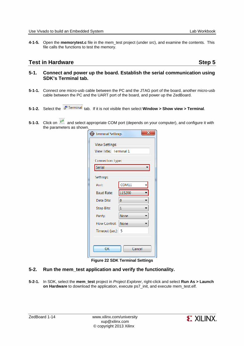
5-1-3. Click on and select appropriate COM port (depends on your computer), and configure it with the parameters as shown.
Figure 22 SDK Terminal Settings
5-2. Run the mem_test application and verify the functionality.
5-2-1. In SDK, select the mem_test project in Project Explorer, right-click and select Run As > Launch on Hardware to download the application, execute ps7_init, and execute mem_test.elf.

Lab Workbook Use Vivado to build an Embedded System
www.xilinx.com/university ZedBoard 1-15 [email protected] © copyright 2013 Xilinx
Figure 23 Launch Application
5-2-2. You should see the following output on the Terminal console.
Figure 24 SDK Terminal Output
5-2-3. Close SDK and Vivado by selecting File > Exit in each program.
Conclusion
Vivado and the IP Integrator allow base embedded processor systems and applications to be generated very quickly. After the system has been defined, the hardware can be exported and SDK can be invoked from Vivado. Software development is done in SDK which provides several application templates including memory tests. You verified the operation of the hardware by downloading a test application, executing on the processor, and observing the output in the serial terminal window.