user and installation manual - schaffner · 2019-10-15 · user and installation manual ecosine evo...
TRANSCRIPT

Schaffner Group | Nordstrasse 11 | 4542 Luterbach | Switzerland
T +41 32 681 66 26 | F+41 32 681 66 30 | www.schaffner.com
User and Installation Manual Ecosine evo Passive Harmonic Filters
Ecosine evo FN 3440/FN 3441 (50 Hz) for 380–415 VAC
FN 3450/FN 3451 (50 Hz) for 440–500 VAC
FN 3442/FN 3443 (60 Hz) for 380–415 VAC
FN 3452/FN 3453 (60 Hz) for 440–480 VAC
Schaffner Group
User and Installation Manual
Ecosine® evo
September 2019
2/54
© All rights reserved.
No part of this publication may be reproduced, stored in a retrieval system, or transmitted in any form or
by any means without the prior written permission of Schaffner International Ltd. The information in this
manual is subject to change without notice. Every precaution has been taken in the preparation of this
manual. Schaffner assumes no responsibility for errors or omissions. Neither is any liability assumed for
damages resulting from the use of the information contained in this publication.
Revision: 07 (September 2019)
The most current edition of these instructions (PDF format) can be obtained from www.schaffner.com or from
your local Schaffner sales representative.
Other technical documentation of our products is also available in the download area of www.schaffner.com
Document name:
User and Installation Manual ecosine evo Rev07.pdf
Version history
Revision Date Description
01 November 2016 Initial version
02
03
February 2017
July 2017
FN 3441/51/53 and IP 20 types added
SCCR
04 January 2018 Update filter selection table of FN3441/51/53 (min. required Lac, Ldc
included)
Add thread size and torque for finger guard
05 October 2018 Add new filter series FN 3442 and FN 3443 (60 Hz, 380VAC)
06 January 2019 Power terminal table (Table 1) updated
Additional information regarding connecting power terminals with TDJ
module in the way added
07 September 2019 Filter earth terminal table (Table 1) updated
Add new filters FN3440/41-250-119 and FN3450/51-315-119 and
information about the applied new frame size J
Schaffner Group
User and Installation Manual
Ecosine evo
Septembe 2019
3/54
i. Ecosine evo passive harmonic filter
Ecosine evo product highlights
Schaffner ecosine evo passive harmonic filters are configurable products which provide a tailored solution to
each specific problem of current harmonics mitigation of 3-phase non-linear loads.
The eight product lines, FN 3440/FN 3441, FN 3450/FN 3451, FN 3442/FN 3443 and FN 3452/FN 3453 are
applicable for low voltage 50 Hz and 60 Hz systems and they are particularly suitable for AC and DC motor
drives, battery chargers and other power electronics applications with 6-pulse front-end rectifiers.
Ecosine evo passive harmonic filter technology represents an evolution of the previous generations of
passive harmonic filters and introduces following aspects of novelty:
| Ecosine evo is designed for the most demanding harmonic mitigation tasks. Ecosine evo filters
FN 3440, FN 3450, FN 3442 and FN 3452 are designed for three-phase diode and thyristor rectifier,
to achieve THID ≤5% even without DC-link choke included in the drive. If there is 8% DC link choke
present in the drive, ecosine evo filters FN 3441, FN 3451, FN 3443 and FN 3453 help to achieve 5%
THID @ rated power. The new generation ecosine evo filters guarantee compliance with the toughest
requirement of IEEE-519 and other stringent international power quality standards.
| Ecosine evo demonstrates superior partial load performance. The excellent performance of
ecosine evo filters not only reflects on mitigating harmonic current and bringing the THID down to 5%
(diode rectifiers @ rated power), but also introducing minimum reactive power, even at partial or no
load condition. The displacement power factor remains at cosφ >0.98 @ 50% load.
| The modular concept of ecosine evo offers optimal tailored solution. Ecosine evo are
configurable filters, optional modules includes fan with aux. power supply, fan without aux. power
supply, trap disconnect jumper and RC damper modules. Optimal solutions can be achieved by
merely plugging a new module according to different installation conditions and drive setups.
| Most compact design, robust, reliable and ready to use.
| The Schaffner ecosine evo product configurator (myecosine.com) supports customers in evaluating
the best suited filter type.
| The upgraded version of the Schaffner power quality simulator SchaffnerPQS3 (pqs.schaffner.com)
provides the possibility to simulate ecosine evo passive harmonic filters within an electrical system. It
furthermore offers quick and accurate performance checks.
This user manual is intended to support designers, installers, and application engineers with filter selection,
installation, application, and maintenance. It provides helpful solutions to overcome harmonics mitigation
challenges and answers frequently asked questions.
If you require additional support, please feel free to contact your local Schaffner representative.

Schaffner Group
User and Installation Manual
Ecosine evo
Septembe 2019
4/54
ii. Performance Guarantee
Selecting and installing the appropriate ecosine evo passive harmonic filter in a variable frequency AC drive
application,variable speed drive application within our published technical specifications we guarantee that
the input current distortion will be less than or equal to 5% THID for standard ecosine evo series filters at
rated power. Ecosine evo filters can also provide similar performance in other drive applications such as
constant torque, DC drives or other phase controlled rectifiers, e.g. SCR drives, but actual THID levels can
vary by load and/or speed and/or firing angle of thyristors and therefore cannot be guaranteed. Consult your
local Schaffner representative for assistance when applying ecosine filters on these types of equipment.
Minimum system Requirements
The guaranteed performance levels of this filter will be achieved when the following system conditions are
met:
| Type of load: Any 3-phase equipment with front-end six-pulse diode rectifier, with
(FN 3441/43/51/53) or without DC-link choke (FN 3440/42/50/52).
| Type of source: 3-phase power line without neutral
| Line impedance: <3% (calculated for the rated filter power)
| Line frequency: 50 Hz ±1 Hz (FN 3440/41, FN 3450/51), 60 Hz ±1 Hz (FN 3442/43, FN 3452/53)
| Line voltage: Nominal line voltage ±10%
| Line voltage unbalance: <1%
| Line voltage distortion: THVD <2%
If a properly sized and installed filter fails to meet the 5% THID level, Schaffner will provide thenecessary
application engineering support or filter replacement at no charge.
iii. Important user notice
Schaffner ecosine evo harmonic filters are designed for the operation on the input (grid) side of power
electronic equipment with six-pulse rectifier front-ends in balanced three-phase power systems, like typically
used in AC or DC motor drives and high power DC supplies. Filter suitability for a given application must be
determined by the user on a case by case basis. Schaffner will not assume liability for any consequential
downtimes or damages resulting from use or application of ecosine filters outside of their specifications.
Ecosine filters are not designed for single-phase or split-phase applications.
Schaffner Group
User and Installation Manual
Ecosine evo
Septembe 2019
5/54
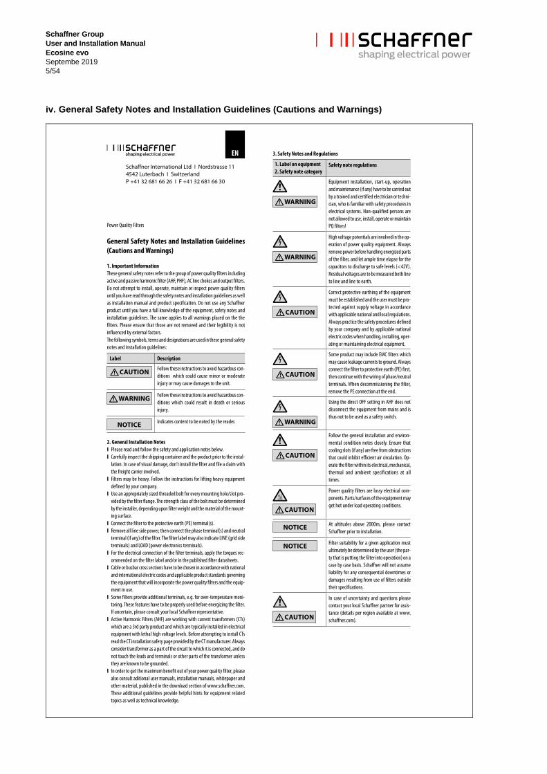
iv. General Safety Notes and Installation Guidelines (Cautions and Warnings)
Schaffner Group
User and Installation Manual
Ecosine evo
Septembe 2019
6/54
Content
Version history .......................................................................................................................................... 2
i. Ecosine evo passive harmonic filter .................................................................................................. 3
Ecosine evo product highlights ........................................................................................................................ 3
ii. Performance Guarantee ...................................................................................................................... 4
Minimum system Requirements .............................................................................................................. 4
iii. Important user notice .......................................................................................................................... 4
iv. General Safety Notes and Installation Guidelines (Cautions and Warnings) ................................ 5
Content ....................................................................................................................................................... 6
1. Ecosine evo passive harmonic filter designation.............................................................................. 8
1.1 Distinguishing between FN 3440/FN 3441, FN 3450/FN 3451, FN 3442/FN 3443 and FN 3452/FN 3453
......................................................................................................................................................................... 8 1.2 Explanation of ecosine evo designation .................................................................................................... 8
2. Filter selection ..................................................................................................................................... 12
2.1 Filter selection table FN 3440/FN 3441 (50 Hz, 3×380 … 415 VAC) ...................................................... 14 2.2 Filter selection table FN 3450/FN 3451 (50 Hz, 3×440 … 500 VAC) ...................................................... 15 2.3 Filter selection table FN 3442/FN 3443 (60 Hz, 3×380 … 415 VAC) ...................................................... 16 2.4 Filter selection table FN 3452/FN 3453 (60 Hz, 3×440 … 480 VAC) ...................................................... 17 2.5 Filter configurations and designations if external air flow is available for cooling ................................... 18 2.6 Filter configurations and designation with embedded ventilation ............................................................ 19 2.7 Filter configurations and designation if external aux. power supply for the fan is available ................... 20 2.8 Frame size J Filter configuration (FN3440/41-250-119, FN3450/51-315-119) ....................................... 21
3. Filter description ................................................................................................................................. 22
3.1 General electrical specifications FN 3440/FN 3441 (50 Hz filters) .......................................................... 22 3.2 General electrical specifications FN 3450/FN 3451 (50 Hz filters) .......................................................... 23 3.3 General electrical specifications FN 3442/FN 3443 (60 Hz filters) .......................................................... 24 3.4 General electrical specifications FN 3452/FN 3453 (60 Hz filters) .......................................................... 25 3.5 Additional electrical specifications ........................................................................................................... 26 3.6 Cooling requirement ................................................................................................................................ 26 3.7 Mechanical frame sizes ........................................................................................................................... 27 3.8 Ecosine evo filter footprint ....................................................................................................................... 29 3.9 Filter performance ................................................................................................................................... 31 3.10 Functional diagram ................................................................................................................................ 33
4. Modular Design: How to choose optional modules ........................................................................ 34
5. Filter appearance and elements ........................................................................................................ 36
5.1 IP 00 version, frame size A - F ................................................................................................................ 36 5.2 IP 00 version, frame size G - H ............................................................................................................... 37 5.3 IP 00 version, frame size J ...................................................................................................................... 37 5.4 IP 20 version ............................................................................................................................................ 38
6. Performance estimation using SchaffnerPQS ................................................................................. 40
7. Filter application.................................................................................................................................. 41
8. Filter installation.................................................................................................................................. 42
9. Filter maintenance .............................................................................................................................. 49

Schaffner Group
User and Installation Manual
Ecosine evo
Septembe 2019
7/54
9.1 Maintenance schedule ............................................................................................................................. 49 9.2 Fan ........................................................................................................................................................... 50 9.3 Power capacitors ..................................................................................................................................... 50 9.4 Electrical connections .............................................................................................................................. 50
10 Trap circuit disconnect ...................................................................................................................... 52
11. Troubleshooting ................................................................................................................................ 53
Disclaimer ................................................................................................................................................ 54
Schaffner Group
User and Installation Manual
Ecosine evo
Septembe 2019
8/54
1. Ecosine evo passive harmonic filter designation
1.1 Distinguishing between FN 3440/FN 3441, FN 3450/FN 3451, FN 3442/FN 3443 and FN 3452/FN 3453
Before going into the details of the designation, it is important to be aware of the difference between
FN 3440 and FN 3441, FN 3450 and FN 3451, FN 3442 and FN 3443, FN 3452 and FN 3453. FN 3440, FN
3450, FN 3442 and FN 3452 are used for motor drives without dc-link choke. They are similar to FN 3441, FN
3451, FN 3443 and FN 3453 except there is one choke less in FN 3441, FN 3451, FN 3443 and FN 3453
series as they are meant to be used for motor drives with dc-link choke (8%) included. In other words, there
are three chokes (line choke, trap choke and load choke) included in filter series FN 3440, FN 3450, FN 3442
and FN 3452, whereas there are only two chokes (line choke, trap choke) included in filter series FN 3441,
FN 3451 FN 3443 and FN 3453 series.
By distinguishing between FN 3440, (FN 3450, FN 3442, FN 3452) as well as FN 3441 (FN 3451, FN 3443,
FN 3453) Schaffner is able to provide optimized solutions for different drive types:
| If there is no DC-link choke present in the motor drive, FN 3440, FN 3450, FN 3442, FN 3452 filter
series help to reduce THID to 5% @ rated power.
| If there is a minimum 8% DC-link choke present in the motor drive, FN 3441, FN 3451, FN 3443, FN
3453 filter series reduce THID to 5% @ rated power
In case you have difficulties to decide for the right filter, please contact your local Schaffner representative for
support.
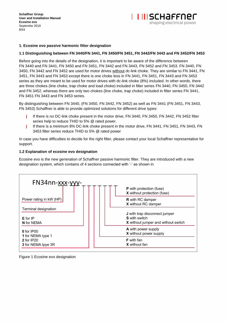
1.2 Explanation of ecosine evo designation
Ecosine evo is the new generation of Schaffner passive harmonic filter. They are introduced with a new
designation system, which contains of 4 sections connected with ‘-’ as shown in
Figure 1 Ecosine evo designation
Schaffner Group
User and Installation Manual
Ecosine evo
Septembe 2019
9/54
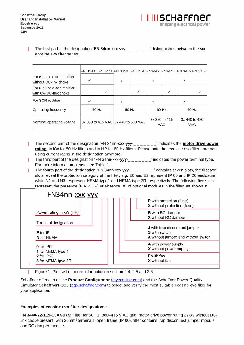
| The first part of the designation ‘FN 34nn-xxx-yyy-_ _ _ _ _ _ _’ distinguishes between the six
ecosine evo filter series.
FN 3440 FN 3441 FN 3450 FN 3451 FN3442 FN3443 FN 3452 FN 3453
For 6-pulse diode rectifier
without DC-link choke ✓ ✓ ✓ ✓
For 6-pulse diode rectifier
with 8% DC-link choke ✓ ✓ ✓ ✓
For SCR rectifier ✓ ✓ ✓ ✓
Operating frequency 50 Hz 50 Hz 60 Hz 60 Hz
Nominal operating voltage 3x 380 to 415 VAC 3x 440 to 500 VAC 3x 380 to 415
VAC
3x 440 to 480
VAC
| The second part of the designation ‘FN 34nn-xxx-yyy-_ _ _ _ _ _ _’ indicates the motor drive power
rating, in kW for 50 Hz filters and in HP for 60 Hz filters. Please note that ecosine evo filters are not
using current rating in the designation anymore.
| The third part of the designation ‘FN 34nn-xxx-yyy-_ _ _ _ _ _ _’ indicates the power terminal type.
For more information please see Table 1.
| The fourth part of the designation ‘FN 34nn-xxx-yyy- _ _ _ _ _ _ _’ contains seven slots, the first two
slots reveal the protection category of the filter, e.g. E0 and E2 represent IP 00 and IP 20 enclosure,
while N1 and N3 respresent NEMA type1 and NEMA type 3R, respectively. The following five slots
represent the presence (F,A,R,J,P) or absence (X) of optional modules in the filter, as shown in
|
| Figure 1. Please find more information in section 2.4, 2.5 and 2.6.
Schaffner offers an online Product Configurator (myecosine.com) and the Schaffner Power Quality
Simulator SchaffnerPQS3 (pqs.schaffner.com) to select and verify the most suitable ecosine evo filter for
your application.
Examples of ecosine evo filter designations:
FN 3440-22-115-E0XXJRX: Filter for 50 Hz, 380–415 V AC grid, motor drive power rating 22kW without DC-
link choke present, with 20mm2 terminals, open frame (IP 00), filter contains trap disconnect jumper module
and RC damper module.

Schaffner Group
User and Installation Manual
Ecosine evo
Septembe 2019
10/54
FN 3441-22-115-E2FAXXX: Filter for 50 Hz, 380–415 V AC grid, motor drive power rating 22kW with 8% DC-
link choke present, with 20mm2 terminals, IP 20 enclosure, filter contains Fan module and auxiliary power
supply module.
FN 3452-150-116-E0XXXXX: Filter for 60 Hz, 440–480 V AC grid, motor drive power rating 150HP with no
DC-link choke present, with 24mm2 terminals, open frame (IP 00), filter contains no optional modules.
FN 3440-250-119-E2FASXX: Filter for 50 Hz, 380–415 V AC grid, motor drive power rating 250kW with no
DC-link choke present, IP20, filter contains Fan module, auxiliary power supply module and switch module.

Schaffner Group
User and Installation Manual
Ecosine evo
Septembe 2019
11/54
Table 1 Ecosine evo filter power terminals designation

Schaffner Group
User and Installation Manual
Ecosine evo
Septembe 2019
12/54
2. Filter selection
Ecosine evo passive harmonic filters need to be carefully selected and configured in order to enjoy maximum
benefits. Besides the enclosed selection tables and the product datasheets included in the online configurator
(myecosine.com), Schaffer advices to verify the selection by using the Schaffner Power Quality Simulator tool
SchaffnerPQS3, available at pqs.schaffner.com.
Step 1: Grid frequency
Determine, whether the system in consideration will be operated in a 50 Hz or 60 Hz electricity grid, and
select the corresponding filter series according to the following table:
50 Hz grid Europe, Middle East, parts of Asia, parts of South America FN 3440/FN 3441
FN 3450/FN 3451
60 Hz grid North and Central America, parts of Asia, parts of South America FN 3442/FN 3443
FN 3452/FN 3453
Note: a 50 Hz filter will not provide satisfying harmonics mitigation in a 60 Hz grid, and vice versa.
Step 2: Grid voltage
Verify that the grid configuration is suitable for standard ecosine evo passive harmonic filters according to the
following table:
50 Hz grid Nominal voltage 380–415 V AC TN, TT, IT configuration
50 Hz grid Nominal voltage 440–500 V AC TN, TT, IT configuration
60 Hz grid Nominal voltage 380–415 V AC TN, TT, IT configuration
60 Hz grid Nominal voltage 440–480 V AC TN, TT, IT configuration
Step 3: Rectifier type, presence of DC-link choke in drive
FN 3440 FN 3441 FN 3450 FN 3451 FN3442 FN3443 FN 3452 FN 3453
For 6-pulse diode rectifier
without DC-link choke ✓ ✓ ✓ ✓
For 6-pulse diode rectifier
with 8% DC-link choke ✓ ✓ ✓ ✓
For SCR rectifier ✓ ✓ ✓ ✓
Note: For 6-pulse diode rectifier with DC-link choke smaller than 8%, it is recommended to choose
FN 3440, FN 3450, FN 3442 or FN 3452 if 5% THID is required.
Step 4: Rectifier/Drive input power
The individual filter must be selected with respect to the rectifier/motor drive input power in kW respectively in
HP. It is important to match rated filter power as close as possible with the effective input power of the
rectifier/drive.
Note that if the rectifier/drive is being operated very close to its rated power, then the filter can be selected by
the motor drive’s nominal power rating. However, if the drive will be operated e.g. at only 66% of its rated
power, then a smaller filter should be selected in order to get maximum harmonics mitigation performance
and the optimum in terms of cost, size, and weight. In that case the customer is responsible to ensure that

Schaffner Group
User and Installation Manual
Ecosine evo
Septembe 2019
13/54
ecosine passive harmonic filter will be operated within specification. This is particular important in terms of
overload.
Please refer to the following examples:
Example 1:
Power line rating: 400 V, 50 Hz
Drive rating: 380–500 V, 50–60 Hz, 15 kW, 22.5 A, B6-diode rectifier without DC-link choke
Planned rectifier/drive input real power: 15kW (100% of drive rating)
➔ Recommended filter according to the filter selection table FN 3440: Type FN 3440-15-113
Example 2:
Power line rating: 400 V, 50 Hz
Drive rating: 380–500 V, 50–60 Hz, 15 kW, 22.5 A, B6-diode rectifier with an 8% DC-link choke
Planned rectifier/drive input real power: 15 kW (100% of drive rating)
➔ Recommended filter according to the filter selection table FN 3441: Type FN 3441-15-113
Example 3:
Power line rating: 500 V, 50 Hz
Drive rating: 380–500 V, 50–60 Hz, 15 kW, 18 A, B6-diode rectifier without DC-link choke
Planned rectifier/drive input real power: 15 kW (100% of drive rating)
➔ Recommended filter according to the filter selection table FN 3450: Type FN 3450-15-113
Example 4:
Power line rating: 500 V, 50 Hz
Drive rating: 380–500 V, 50–60 Hz, 15 kW, 18 A, B6-thyristor rectifier
Planned rectifier/drive input real power: 15 kW (100% of drive rating)
➔ Recommended filter according to the filter selection table FN 3450: Type FN 3450-15-113
Example 5:
Power line rating: 400 V, 50 Hz
Drive rating: 380–500 V, 50–60 Hz, 15 kW, 22.5 A, diode rectifier
Planned rectifier/drive input real power: 10 kW (66% of drive rating)
➔ Recommended filter according to the filter selection table FN 3440: Type FN 3440-11-113
Example 6:
Power line rating: 480 V, 60 Hz
Drive rating: 380–500 V, 50–60 Hz, 30 HP, 41 A, diode rectifier
Planned rectifier/drive input real power: 30 HP (100% of drive rating)
➔ Recommended filter according to the filter selection table FN 3452: Type FN 3452-30-113
Oversizing of passive harmonic filters is not recommended because of the inherent lower harmonic mitigation
performance at partial load as well as higher cost, size, and weight.
Please refer to Table 2 - Table 9 to select suitable filters.

Schaffner Group
User and Installation Manual
Ecosine evo
Septembe 2019
14/54
2.1 Filter selection table FN 3440/FN 3441 (50 Hz, 3×380 … 415 VAC)
Table 2 FN 3440 filter selection table
Table 3 FN 3441 filter selection table
Schaffner Group
User and Installation Manual
Ecosine evo
Septembe 2019
15/54
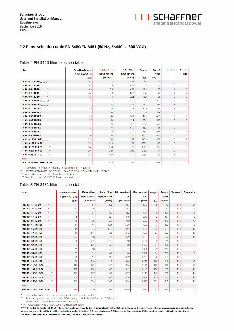
2.2 Filter selection table FN 3450/FN 3451 (50 Hz, 3×440 … 500 VAC)
Table 4 FN 3450 filter selection table
Table 5 FN 3451 filter selection table

Schaffner Group
User and Installation Manual
Ecosine evo
Septembe 2019
16/54
2.3 Filter selection table FN 3442/FN 3443 (60 Hz, 3×380 … 415 VAC)
Table 6 FN 3442 filter selection table
Table 7 FN 3443 filter selection table
Schaffner Group
User and Installation Manual
Ecosine evo
Septembe 2019
17/54
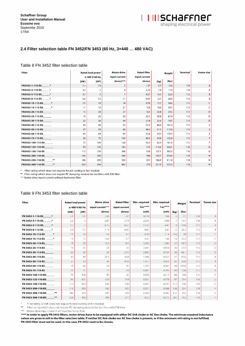
2.4 Filter selection table FN 3452/FN 3453 (60 Hz, 3×440 … 480 VAC)
Table 8 FN 3452 filter selection table
Table 9 FN 3453 filter selection table
Schaffner Group
User and Installation Manual
Ecosine evo
Septembe 2019
18/54
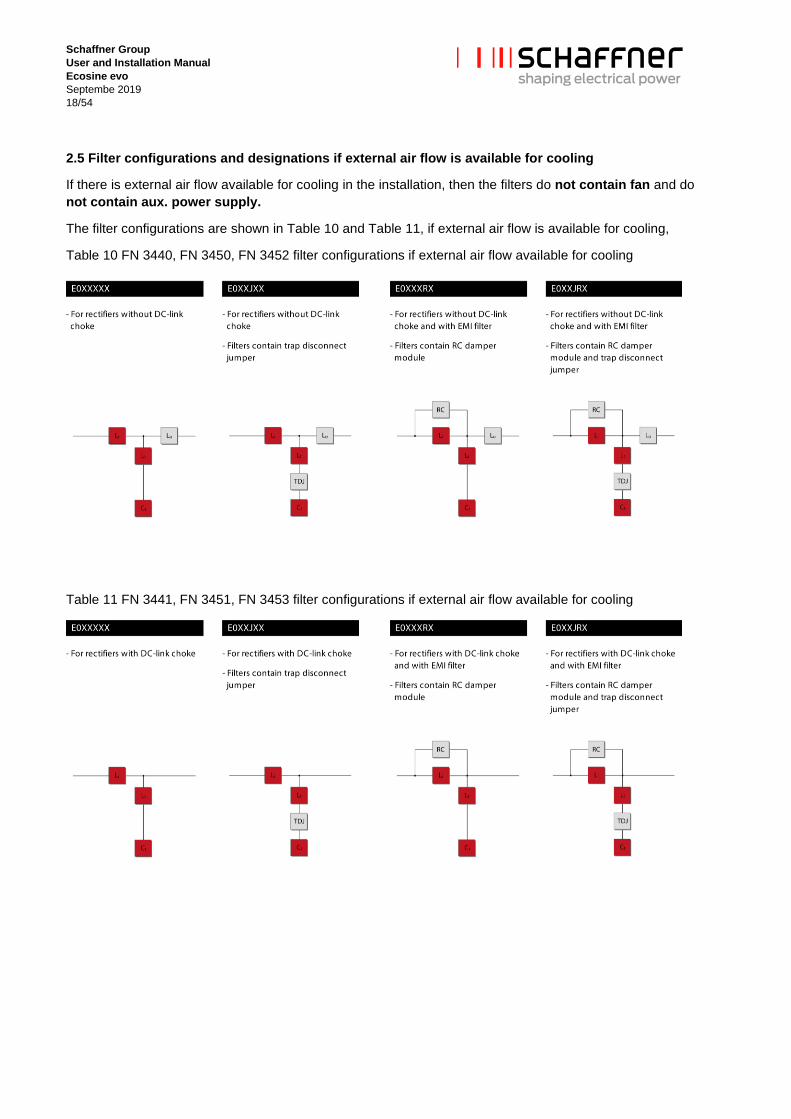
2.5 Filter configurations and designations if external air flow is available for cooling
If there is external air flow available for cooling in the installation, then the filters do not contain fan and do
not contain aux. power supply.
The filter configurations are shown in Table 10 and Table 11, if external air flow is available for cooling,
Table 10 FN 3440, FN 3450, FN 3452 filter configurations if external air flow available for cooling
Table 11 FN 3441, FN 3451, FN 3453 filter configurations if external air flow available for cooling

Schaffner Group
User and Installation Manual
Ecosine evo
Septembe 2019
19/54
2.6 Filter configurations and designation with embedded ventilation
If external air flow for cooling is not available, then the filters contain embedded ventilation, which means the
filters contain fan and aux. power supply.
The open frame filter configurations are shown in Table 12 and Table 13, if external air flow is not available
and embedded ventilation is equipped.
Table 12 FN 3440, FN 3450, FN 3452 filter configurations with embedded ventilation
Table 13 FN 3441, FN 3451, FN 3453 filter configurations with embedded ventilation
Remark: Frame sizes A, B, C do not require air-flow for cooling hence they are not equipped with FAN and
AUX.
Schaffner Group
User and Installation Manual
Ecosine evo
Septembe 2019
20/54
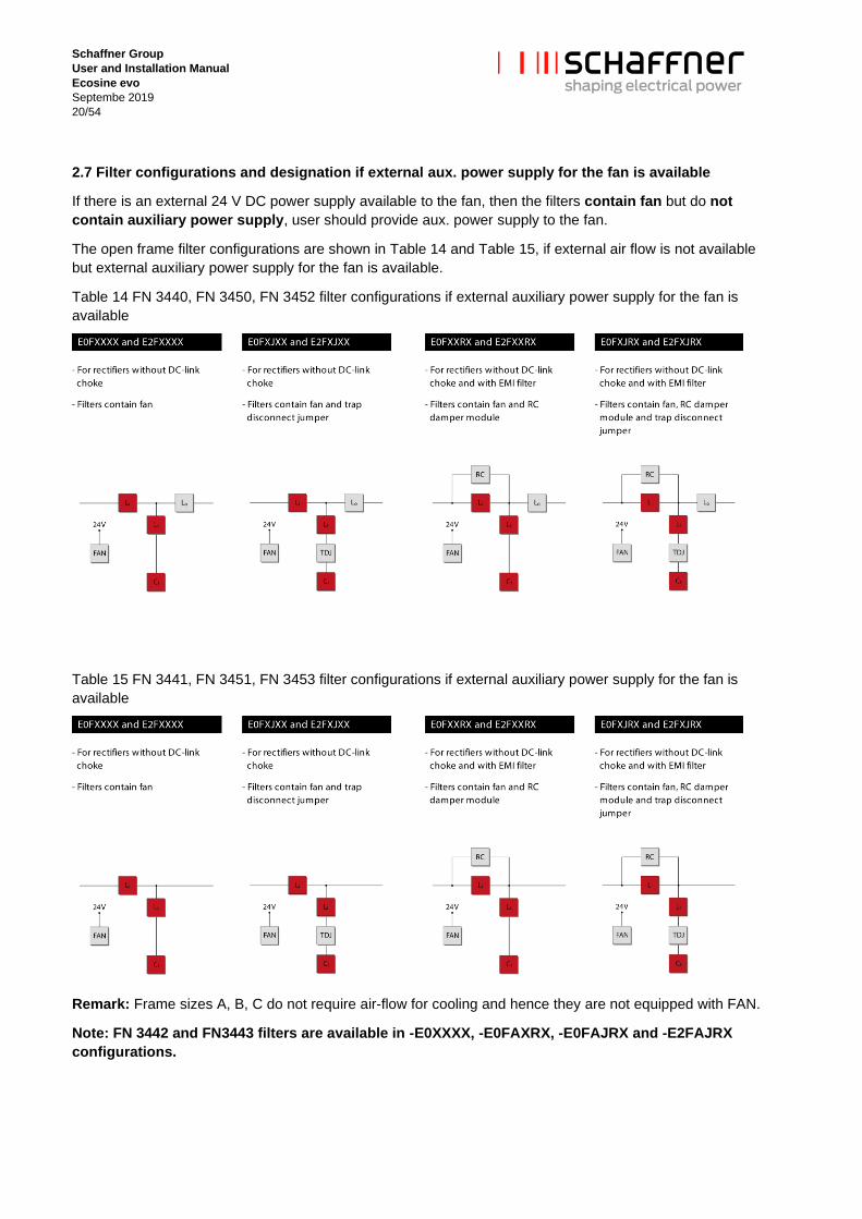
2.7 Filter configurations and designation if external aux. power supply for the fan is available
If there is an external 24 V DC power supply available to the fan, then the filters contain fan but do not
contain auxiliary power supply, user should provide aux. power supply to the fan.
The open frame filter configurations are shown in Table 14 and Table 15, if external air flow is not available
but external auxiliary power supply for the fan is available.
Table 14 FN 3440, FN 3450, FN 3452 filter configurations if external auxiliary power supply for the fan is
available
Table 15 FN 3441, FN 3451, FN 3453 filter configurations if external auxiliary power supply for the fan is
available
Remark: Frame sizes A, B, C do not require air-flow for cooling and hence they are not equipped with FAN.
Note: FN 3442 and FN3443 filters are available in -E0XXXX, -E0FAXRX, -E0FAJRX and -E2FAJRX
configurations.

Schaffner Group
User and Installation Manual
Ecosine evo
Septembe 2019
21/54
2.8 Frame size J Filter configuration (FN3440/41-250-119, FN3450/51-315-119)

Schaffner Group
User and Installation Manual
Ecosine evo
Septembe 2019
22/54
3. Filter description
3.1 General electrical specifications FN 3440/FN 3441 (50 Hz filters)
Nominal operating voltage: 3x 380 to 415 V AC
Voltage tolerance range: 3x 342 to 457 V AC
Operating frequency: 50 Hz ±1 Hz
Network: TN, TT, IT
Nominal motor drive input power rating: 1.1 to 250kW
Total harmonic current distortion THID: 2) <5% @ rated power 1)
Total demand distortion TDD: 2) According to IEEE 519
Efficiency: >98% @ nominal line voltage and power
Drive dc-link voltage: 3) -5% ~ +10% nominal VDC
High potential test voltage: 4) P → E 2160 VAC (1s)
SCCR: 5) 100kA, fuses according UL class J
Protection category: IP 00, IP 20
Pollution degree: PD3 (according to standard IEC 60664-1)
Cooling: Internal fan cooling or external cooling 6)
Overload capability: 1.6x rated current for 1 minute, once per hour
Capacitive current @ no load: <20% of rated input current, at 400 V AC
Ambient temperature range:
-25°C to +45°C fully operational
+45°C to +70°C derated operation 7)
-25°C to +85°C transportation and storage
Flammability class: UL 94V-2
Insulation class of magnetic components: N (200°C), H (180°C)
Design corresponding to: Filter: UL 61800-5-1, EN 61800-5-1
Chokes: EN 61558-2-20 or EN 60076-6
MTBF @ 45°C/415 V (Mil-HB-217F): >200,000 hours
MTTR: <15 minutes (capacitor modules and fan modules)
Lifetime (calculated): ≥10 years
Safety monitor output signal: Thermal switch NC 180° C (UL-approved) to detect
overload of chokes
1) THID ~5% at rated power for filter <4kW. 2) System requirements: THVD <2%, line voltage unbalance <1%
Performance specification for six-pulse diode rectifiers. SCR rectifier front-ends produce different results, depending upon
the firing angle of the thyristors. 3) Conditions: line impedance <3% 4) Repetitive tests to be performed at max. 80% of above levels, for 2 seconds. 5) External UL-rated fuses required. 6) Please check the inlet air flow required for cooling in Table 17 7) Iderated = Inominal×((70°C-Tamb)/25°C)
Schaffner Group
User and Installation Manual
Ecosine evo
Septembe 2019
23/54
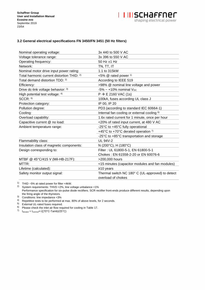
3.2 General electrical specifications FN 3450/FN 3451 (50 Hz filters)
Nominal operating voltage: 3x 440 to 500 V AC
Voltage tolerance range: 3x 396 to 550 V AC
Operating frequency: 50 Hz ±1 Hz
Network: TN, TT, IT
Nominal motor drive input power rating: 1.1 to 315kW
Total harmonic current distortion THID: 2) <5% @ rated power 1)
Total demand distortion TDD: 2) According to IEEE 519
Efficiency: >98% @ nominal line voltage and power
Drive dc-link voltage behavior: 3) -5% ~ +10% nominal VDC
High potential test voltage: 4) P → E 2160 VAC (1s)
SCCR: 5) 100kA, fuses according UL class J
Protection category: IP 00, IP 20
Pollution degree: PD3 (according to standard IEC 60664-1)
Cooling: Internal fan cooling or external cooling 6)
Overload capability: 1.6x rated current for 1 minute, once per hour
Capacitive current @ no load: <20% of rated input current, at 480 V AC
Ambient temperature range:
-25°C to +45°C fully operational
+45°C to +70°C derated operation 7)
-25°C to +85°C transportation and storage
Flammability class: UL 94V-2
Insulation class of magnetic components: N (200°C), H (180°C)
Design corresponding to: Filter : UL 61800-5-1, EN 61800-5-1
Chokes : EN 61558-2-20 or EN 60076-6
MTBF @ 45°C/415 V (Mil-HB-217F): >200,000 hours
MTTR: <15 minutes (capacitor modules and fan modules)
Lifetime (calculated): ≥10 years
Safety monitor output signal: Thermal switch NC 180° C (UL-approved) to detect
overload of chokes
1) THID ~5% at rated power for filter <4kW. 2) System requirements: THVD <2%, line voltage unbalance <1%
Performance specification for six-pulse diode rectifiers. SCR rectifier front-ends produce different results, depending upon
the firing angle of the thyristors. 3) Conditions: line impedance <3% 4) Repetitive tests to be performed at max. 80% of above levels, for 2 seconds. 5) External UL-rated fuses required. 6) Please check the inlet air flow required for cooling in Table 17. 7) Iderated = Inominal×((70°C-Tamb)/25°C)

Schaffner Group
User and Installation Manual
Ecosine evo
Septembe 2019
24/54
3.3 General electrical specifications FN 3442/FN 3443 (60 Hz filters)
Nominal operating voltage: 3x 380 to 415 V AC
Voltage tolerance range: 3x 342 to 456 V AC
Operating frequency: 60 Hz ±1 Hz
Network: TN, TT, IT
Nominal motor drive input power rating: 1 to 240 HP (0.9 to 177 kW)
Total harmonic current distortion THID: 2) <5% @ rated power 1)
Total demand distortion TDD: 2) According to IEEE 519
Efficiency: >98% @ nominal line voltage and power
Drive dc-link voltage: 3) -5% ~ +10% nominal VDC
High potential test voltage: 4) P → E 2160 VAC (1s)
SCCR: 5) 100kA, fuses according UL class J
Protection category: IP 00, IP 20
Pollution degree: PD3 (according to standard IEC 60664-1)
Cooling: Internal fan cooling or external cooling 6)
Overload capability: 1.6x rated current for 1 minute, once per hour
Capacitive current @ no load: <20% of rated input current, at 480 V AC
Ambient temperature range:
-25°C to +45°C fully operational
+45°C to +70°C derated operation 7)
-25°C to +85°C transportation and storage
Flammability class: UL 94V-2
Insulation class of magnetic components: N (200°C), H (180°C)
Design corresponding to: Filter : UL 61800-5-1, EN 61800-5-1
Chokes : EN 61558-2-20 or EN 60076-6
MTBF @ 45°C/415 V (Mil-HB-217F): >200,000 hours
MTTR: <15 minutes (capacitor modules and fan modules)
Lifetime (calculated): ≥10 years
Safety monitor output signal: Thermal switch NC 180° C (UL-approved) to detect
overload of chokes
1) THID ~5% at rated power for filter <4kW. 2) System requirements: THVD <2%, line voltage unbalance <1%
Performance specification for six-pulse diode rectifiers. SCR rectifier front-ends produce different results, depending upon
the firing angle of the thyristors. 3) Conditions: line impedance <3% 4) Repetitive tests to be performed at max. 80% of above levels, for 2 seconds. 5) External UL-rated fuses required. 6) Please check the inlet air flow required for cooling in Table 17 7) Iderated = Inominal×((70°C-Tamb)/25°C)

Schaffner Group
User and Installation Manual
Ecosine evo
Septembe 2019
25/54
3.4 General electrical specifications FN 3452/FN 3453 (60 Hz filters)
Nominal operating voltage: 3x 440 to 480 V AC
Voltage tolerance range: 3x 396 to 528 V AC
Operating frequency: 60 Hz ±1 Hz
Network: TN, TT, IT
Nominal motor drive input power rating: 1.5 to 300 HP (1.1 to 224 kW)
Total harmonic current distortion THID: 2) <5% @ rated power 1)
Total demand distortion TDD: 2) According to IEEE 519
Efficiency: >98% @ nominal line voltage and power
Drive dc-link voltage: 3) -5% ~ +10% nominal VDC
High potential test voltage: 4) P → E 2160 VAC (1s)
SCCR: 5) 100kA, fuses according UL class J
Protection category: IP 00, IP 20
Pollution degree: PD3 (according to standard IEC 60664-1)
Cooling: Internal fan cooling or external cooling 6)
Overload capability: 1.6x rated current for 1 minute, once per hour
Capacitive current @ no load: <20% of rated input current, at 480 V AC
Ambient temperature range:
-25°C to +45°C fully operational
+45°C to +70°C derated operation 7)
-25°C to +85°C transportation and storage
Flammability class: UL 94V-2
Insulation class of magnetic components: N (200°C), H (180°C)
Design corresponding to: Filter : UL 61800-5-1, EN 61800-5-1
Chokes : EN 61558-2-20 or EN 60076-6
MTBF @ 45°C/415 V (Mil-HB-217F): >200,000 hours
MTTR: <15 minutes (capacitor modules and fan modules)
Lifetime (calculated): ≥10 years
Safety monitor output signal: Thermal switch NC 180° C (UL-approved) to detect
overload of chokes
1) THID ~5% at rated power for filter <6HP. 2) System requirements: THVD <2%, line voltage unbalance <1%
Performance specification for six-pulse diode rectifiers. SCR rectifier front-ends produce different results, depending upon
the firing angle of the thyristors. 3) Conditions: line impedance <3% 4) Repetitive tests to be performed at max. 80% of above levels, for 2 seconds. 5) External UL-rated fuses required. 6) Please check the inlet air flow required for cooling in Table 17. 7) Iderated = Inominal×((70°C-Tamb)/25°C)
Schaffner Group
User and Installation Manual
Ecosine evo
Septembe 2019
26/54
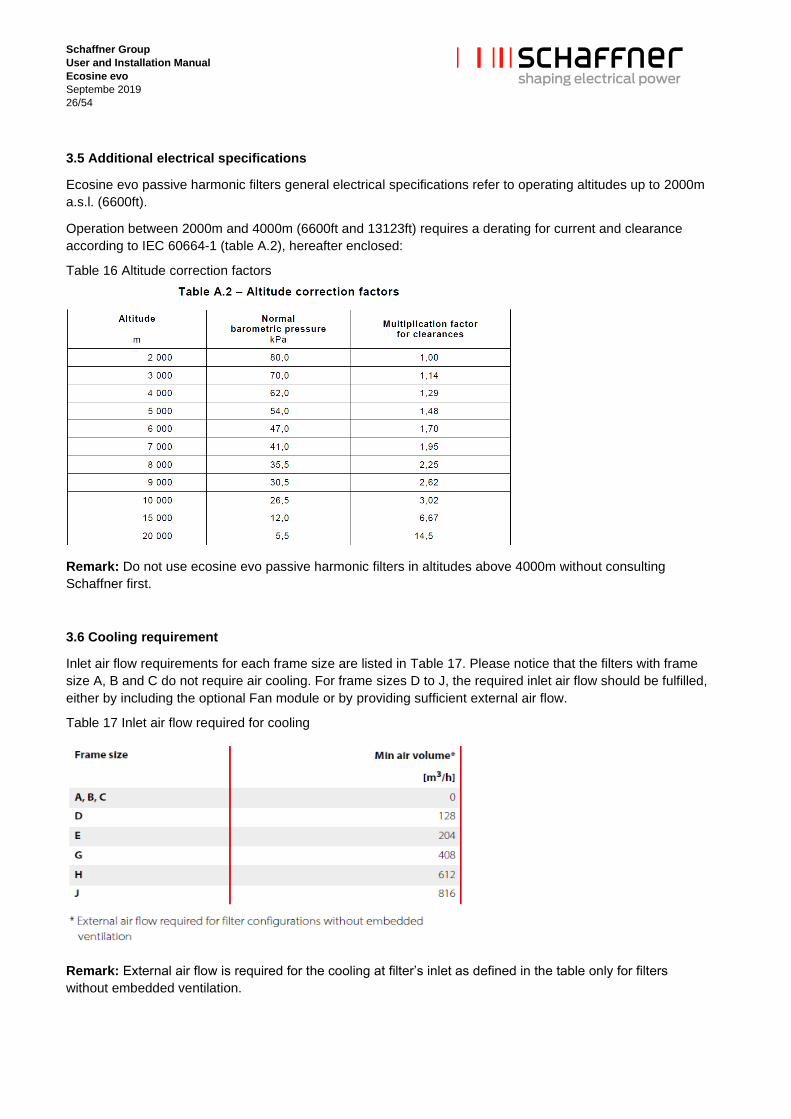
3.5 Additional electrical specifications
Ecosine evo passive harmonic filters general electrical specifications refer to operating altitudes up to 2000m
a.s.l. (6600ft).
Operation between 2000m and 4000m (6600ft and 13123ft) requires a derating for current and clearance
according to IEC 60664-1 (table A.2), hereafter enclosed:
Table 16 Altitude correction factors
Remark: Do not use ecosine evo passive harmonic filters in altitudes above 4000m without consulting
Schaffner first.
3.6 Cooling requirement
Inlet air flow requirements for each frame size are listed in Table 17. Please notice that the filters with frame
size A, B and C do not require air cooling. For frame sizes D to J, the required inlet air flow should be fulfilled,
either by including the optional Fan module or by providing sufficient external air flow.
Table 17 Inlet air flow required for cooling
Remark: External air flow is required for the cooling at filter’s inlet as defined in the table only for filters
without embedded ventilation.

Schaffner Group
User and Installation Manual
Ecosine evo
Septembe 2019
27/54
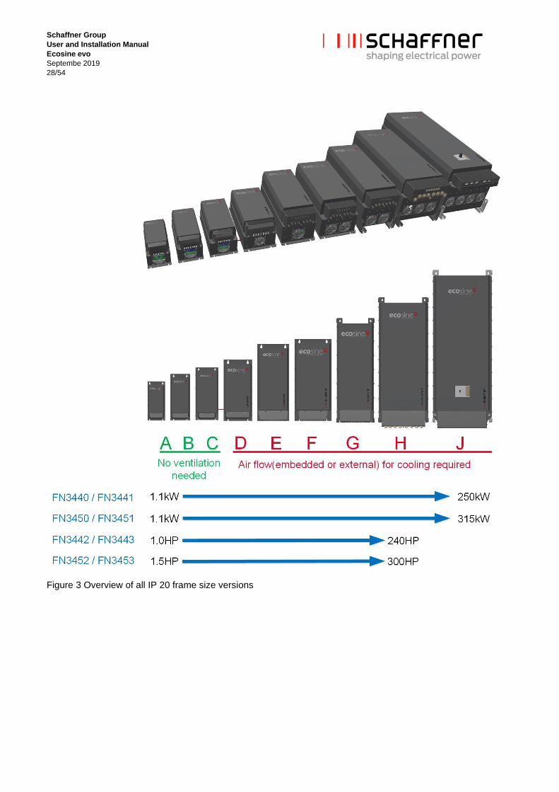
3.7 Mechanical frame sizes
Ecosine evo passive harmonic filters are implemented on a base plate or base frame featuring 9 different
frame sizes, Frame A to Frame J, from the lowest to the highest rating. Dimensions and footprint are provided
in section 3.7.
In particular, frame sizes A to C do not require air flow, while frame sizes D to J need embedded fan or
external ventilation, details are provided in filter selection tables, Table 2 to Table 9. The overview of all frame
sizes in IP 00 and IP 20 are shown in Figure 2 and Figure 3.
Figure 2 Overview of all IP 00 frame size versions
Schaffner Group
User and Installation Manual
Ecosine evo
Septembe 2019
28/54
Figure 3 Overview of all IP 20 frame size versions

Schaffner Group
User and Installation Manual
Ecosine evo
Septembe 2019
29/54
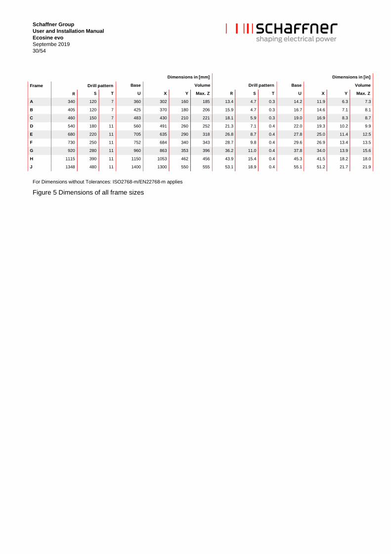
3.8 Ecosine evo filter footprint
Figure 4 Mechanical Data of FN 3440, FN 3450, FN 3442 and FN 3452
Schaffner Group
User and Installation Manual
Ecosine evo
Septembe 2019
30/54
Dimensions in [mm]
Dimensions in [in]
Frame Drill pattern Base Volume Drill pattern Base Volume
R S T U X Y Max. Z R S T U X Y Max. Z
A 340 120 7 360 302 160 185 13.4 4.7 0.3 14.2 11.9 6.3 7.3
B 405 120 7 425 370 180 206 15.9 4.7 0.3 16.7 14.6 7.1 8.1
C 460 150 7 483 430 210 221 18.1 5.9 0.3 19.0 16.9 8.3 8.7
D 540 180 11 560 491 260 252 21.3 7.1 0.4 22.0 19.3 10.2 9.9
E 680 220 11 705 635 290 318 26.8 8.7 0.4 27.8 25.0 11.4 12.5
F 730 250 11 752 684 340 343 28.7 9.8 0.4 29.6 26.9 13.4 13.5
G 920 280 11 960 863 353 396 36.2 11.0 0.4 37.8 34.0 13.9 15.6
H 1115 390 11 1150 1053 462 456 43.9 15.4 0.4 45.3 41.5 18.2 18.0
J 1348 480 11 1400 1300 550 555 53.1 18.9 0.4 55.1 51.2 21.7 21.9
For Dimensions without Tolerances: ISO2768-m/EN22768-m applies
Figure 5 Dimensions of all frame sizes

Schaffner Group
User and Installation Manual
Ecosine evo
Septembe 2019
31/54
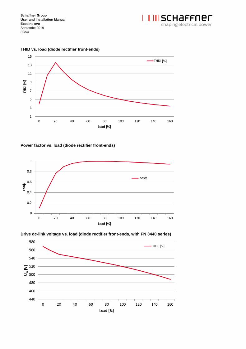
3.9 Filter performance
Ecosine evo passive harmonic filters achieve 5% THID with 6-pulse diode rectifiers under the following
condition.
Filter is applied to rated voltage and power
THVD <2%, line voltage unbalance <1%
RC damper module is required to be included in the filter if there is EMI filter present in the drive. Typical
expected EMI filter capacitance (phase to star point) are shown in
Table 18 and
Table 19.
Table 18 Typical expected EMI filter capacitance (phase to star point) for series FN 3440/FN 3441 and FN
3450/FN 3451
1.1 kW 1.5 µF
2.2 kW 2.2 µF
4-11kW 3.3 µF
15 to 45 kW 4.7 µF
55 to 250(315) kW 10 µF
Table 19 Typical expected EMI filter capacitance (phase to star point) for FN 3442/FN 3443 and FN 3452/FN
3453
1.5 HP 1.5 µF
3 HP 2.2 µF
5-20HP 3.3 µF
25 to 60 HP 4.7 µF
75 to 300 HP 10 µF
| Note: 132…200 kW of FN 3440/FN 3441 series, 160…250 kW of FN 3450/FN 3451 series
200…240HP of FN 3442/FN 3443 series, and 250…300HP of FN 3452/FN 3453 series do not need
RC damper module when the equivalent phase to star point capacitance of the EMI filter is not bigger
than 10 µF.
| 5% THID is not guaranteed for thyristor rectifier application. The performance of the filter is
dependent on the firing angle of the thyristors.
| Ecosine evo filter performance (THID, power factor and Udc) under different load conditions with are
shown in the following charts.
Schaffner Group
User and Installation Manual
Ecosine evo
Septembe 2019
32/54
THID vs. load (diode rectifier front-ends)
Power factor vs. load (diode rectifier front-ends)
Drive dc-link voltage vs. load (diode rectifier front-ends, with FN 3440 series)

Schaffner Group
User and Installation Manual
Ecosine evo
Septembe 2019
33/54
3.10 Functional diagram
Filter terminals Line L1/L2/L3 3 terminal blocks
Load L1’/L2’/L3’ 3 terminal blocks
Signal Connecting terminals to thermal switch NC 180°C (UL-
approved) to detect overload in chokes
PE Protective earth. Threaded stud with washer and nut
Trap disconnect
D1, D2, D3
D1’, D2’, D3’
3 couples of terminals. For optional configurations with TDJ,
wire bridges are installed for immediate operation of the
filter. They allow for the connection of an external contactor
for load dependent disconnection of the trap circuit, if
needed.
Function blocks Chokes Power magnetic components incl. temperature sensors
Capacitors Power capacitors incl. discharge resistors
Fan Field replaceable fan for choke air cooling
Power supply Internally generate 24 V DC source for fan supply
RC damper RC damper module, as option configurable in case of
rectifier equipped with EMI filter
Schaffner Group
User and Installation Manual
Ecosine evo
Septembe 2019
34/54
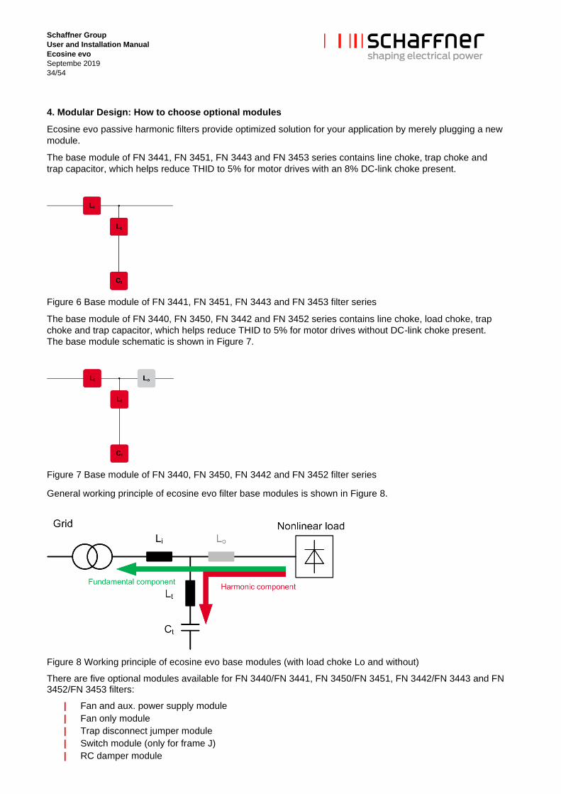
4. Modular Design: How to choose optional modules
Ecosine evo passive harmonic filters provide optimized solution for your application by merely plugging a new
module.
The base module of FN 3441, FN 3451, FN 3443 and FN 3453 series contains line choke, trap choke and
trap capacitor, which helps reduce THID to 5% for motor drives with an 8% DC-link choke present.
Figure 6 Base module of FN 3441, FN 3451, FN 3443 and FN 3453 filter series
The base module of FN 3440, FN 3450, FN 3442 and FN 3452 series contains line choke, load choke, trap
choke and trap capacitor, which helps reduce THID to 5% for motor drives without DC-link choke present.
The base module schematic is shown in Figure 7.
Figure 7 Base module of FN 3440, FN 3450, FN 3442 and FN 3452 filter series
General working principle of ecosine evo filter base modules is shown in Figure 8.
Figure 8 Working principle of ecosine evo base modules (with load choke Lo and without)
There are five optional modules available for FN 3440/FN 3441, FN 3450/FN 3451, FN 3442/FN 3443 and FN 3452/FN 3453 filters:
| Fan and aux. power supply module
| Fan only module
| Trap disconnect jumper module
| Switch module (only for frame J)
| RC damper module

Schaffner Group
User and Installation Manual
Ecosine evo
Septembe 2019
35/54
Figure 9 shows a summary of optional modules in use with ecosine evo passive harmonic filters.
Figure 9 Optional modules for ecosine evo filter and according to your requirement and installation

Schaffner Group
User and Installation Manual
Ecosine evo
Septembe 2019
36/54
5. Filter appearance and elements
The very compact and neat design of ecosine evo passive harmonic filters is realized by a two-stage
construction. The filter construction of all frame size are identical, except the position of the load choke. The
load choke is build on the upper-stage of the filter for frame size A- F, and on the lower-stage of the filter for
frame sizes G – H, which are explained in detail in the following sections.
5.1 IP 00 version, frame size A - F
The general design of the ecosine evo passive harmonic filter IP 00 versions with fan module, aux. power
supply module, TDJ module and RC damper module (E0FAJRX) is shown in Figure 10.
There are load choke Lo, trap capacitor Ct, trap disconnect jumper, power terminal and fan module visible on
the upper-stage. The design and construction of the lower-stage is shown in Figure 11. The line choke Li, trap
choke Lt, RC damper module are constructed on the base plate, which contains screw holes for wall
mounting.
Figure 10 Design of ecosine evo filter (Type E0FAJRX, frame size D): Upper-stage
Figure 11 Lower-stage of ecosine evo filter (Type E0FAJRX, frame size D): lower-stage

Schaffner Group
User and Installation Manual
Ecosine evo
Septembe 2019
37/54
5.2 IP 00 version, frame size G - H
The design of the ecosine evo filter IP 00 versions with fan module, aux. power supply module, TDJ module
and RC damper module (E0FAJRX) is shown in Figure 12.
There are trap capacitor Ct, trap disconnect jumper, power terminal visible on the upper-stage. The fan
module is visible between the upper and lower stage. The design and construction of the lower-stage is
shown in Figure 13. The line choke Li, trap choke Lt, load chock Lo, RC damper module are constructed on
the base plate, which contains screw holes for wall mounting.
Figure 12 Design of ecosine evo filter (Type E0FAJRX, frame size H): Upper-stage
Figure 13 Design of ecosine evo filter (Type E0FAJRX, frame size H): Lower-stage
5.3 IP 00 version, frame size J
FN3440/41-250-119 and FN3450/51-315-119 are constructed with frame size J, which is the biggest among
all the frame sizes used for ecosine evo series. The IP00 version of frame size J contains only switch module,
without other optional modules.
There are trap capacitor Ct, switch module (circuit breaker), power terminal visible on the upper-stage, which
is presented in Figure 14. The design and construction of the lower-stage is shown in Figure 15. The line
choke Li, trap choke Lt, load chock Lo, are constructed on the base plate, which contains screw holes for wall
mounting.

Schaffner Group
User and Installation Manual
Ecosine evo
Septembe 2019
38/54
Figure 14 Design of ecosine evo frame J, E0XXSXX: Upper-stage
Figure 15 Design of ecosine evo frame J, E0XXSXX: Lower-stage
Switch module, namely a circuit breaker, is required for frame size J for safety reasons. The short circuit
current of FN3440/41-250-119 and FN3450/51-315-119 (constructed with frame J) can go beyond 10’000A,
however the capacitors are only protected with failure current of max. 10’000A. Therefore an external switch
to switch off the capacitors is mandatory to ensure the installation safety at all operation situations. Circuit
breaker will be released under overloading and short circuit conditions. When the filter is overloaded,
depending on the overcurrent value, circuit breaker will release after certain time. The higher the current, the
faster will the circuit breaker release. The characteristics curve of current and tripping time and more
information can be found in the datasheet of NZMN2-AF175-NA circuit breaker. In case the circuit breaker is
released, the connected load must be shut down immediately. Until the failure is investigated, and problem is
solved, the circuit breaker can be switched on again to re-start the system.
5.4 IP 20 version
Ecosine evo passvie harmonic filters IP 20 versions are shown in Figure 16 and Figure 17. IP 20 versions of
ecosine evo filters are additionally equipped with cover and finger guard on top of the IP 00 version filters.
IP20 version of frame size J contains fan module, aux. power supply module and switch module (E2FASXX)
is shown in Figure 17.

Schaffner Group
User and Installation Manual
Ecosine evo
Septembe 2019
39/54
Figure 16 Design of IP 20 version ecosine evo filter with frame size D (left) and frame size H (right)
Figure 17 Design of IP 20 version ecosine evo filter with frame size J
Parameters of IP 20 enclosure finger guard are shown in Table 20.
Table 20 Parameters of finger guard of IP 20 enclosure
Frame size Finger guard cross-section width
/diameter
mm
Material
A 5.5 Plastic
B 8.0 Plastic
C 8.0 Plastic
D 11 Plastic
E 14 Metal
F 14 Metal
G 18.5 Metal
H 30 Metal
J 42 Metal
Schaffner Group
User and Installation Manual
Ecosine evo
Septembe 2019
40/54
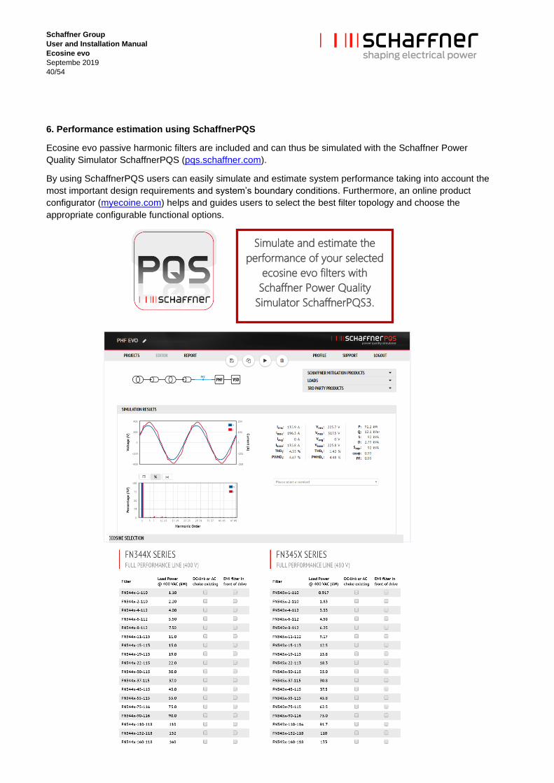
6. Performance estimation using SchaffnerPQS
Ecosine evo passive harmonic filters are included and can thus be simulated with the Schaffner Power
Quality Simulator SchaffnerPQS (pqs.schaffner.com).
By using SchaffnerPQS users can easily simulate and estimate system performance taking into account the
most important design requirements and system’s boundary conditions. Furthermore, an online product
configurator (myecoine.com) helps and guides users to select the best filter topology and choose the
appropriate configurable functional options.
Simulate and estimate the
performance of your selected
ecosine evo filters with
Schaffner Power Quality
Simulator SchaffnerPQS3.

Schaffner Group
User and Installation Manual
Ecosine evo
Septembe 2019
41/54
7. Filter application
Ecosine evo passive harmonic filters are designed to mitigate harmonic current of non-linear loads, in
particular of three-phase diode-type rectifiers. Contrary to “bus-applied or PCC” filters, which are being
installed e.g. at the main feeder, they are specifically designed to be used with either an individual non-linear
load, or with a group of non-linear loads.
One advantage of load-applied filtering is the fact that the upstream power (relative to the harmonic filter) is
clean, i.e. unloaded by the harmonics. This can be of vital importance when the same power bus supplies
both motor drives and sensitive loads. Ecosine evo passive harmonic filters are also suitable for paralleling
lower power non-linear loads on a higher power harmonic filter to improve overall system economy. In this
case the total expected load power of all connected drives must match the filter.
If the expected input power exceeds the rating of the largest available filter, and a custom solution is not
desired, then two or more filters can be wired in parallel. In this mode of operation, it is recommended to use
filters with equal power ratings to ensure proper current sharing.
Schaffner Group
User and Installation Manual
Ecosine evo
Septembe 2019
42/54
8. Filter installation
Please follow the simple steps below to ensure a safe and reliable filter function for many years. Please do
also always follow the general safety and installation guidelines provided within this document as well as
relevant local, national or international standards that are applicable. Please note that the following
installation steps are applicable for both IP 00 and IP 20 enclosure.
Step 1: Visual inspection
All Schaffner ecosine evo passive harmonic filters have undergone rigorous testing before they left our ISO
9001:2008 certified factories. They are packaged with great care in a sturdy container for international
shipment.
However, carefully inspect the shipping container for damage that may have occurred in transit. Then unpack
the filter and carefully inspect for any signs of damage. Keep the shipping container for future transportation
of the filter.
In the case of damage, please file a claim with the freight forwarder involved immediately and contact your
local Schaffner partner for support. Under no circumstances install and energize a filter with visible
transportation damage.
If the filter is not going to be put in service upon receipt, store within the original container in a clean, dry
location, free of dust and chemicals and with respect to named temperature limits, see section 3.2.
Step 2: Mounting
Ecosine evo passive harmonic filters are best installed as close as possible to the non-linear load. Ideally
they are mounted next to the rectifier or motor drive inside the electrical cabinet or control room.
All ecosine evo passive harmonic filters FN 3440/FN 3441, FN 3450/FN 3451, FN 3442/FN 3443, FN
3452/FN 3453 are designed for wall-mounting installation.
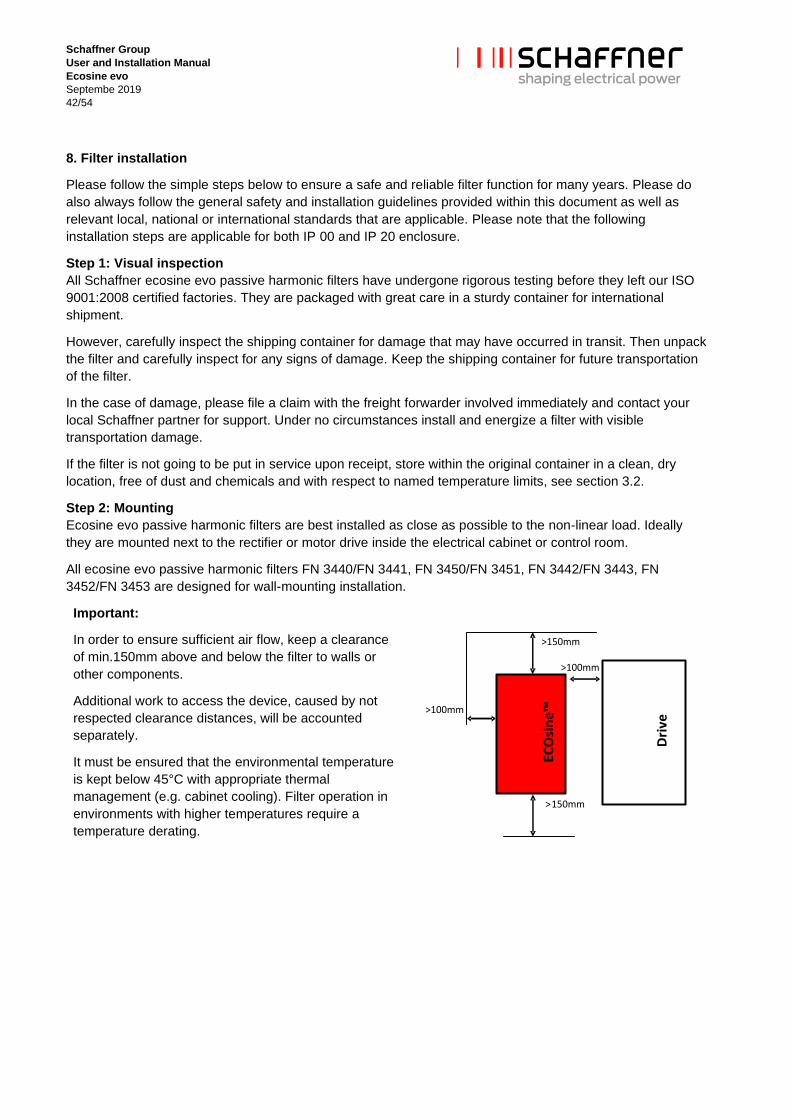
Important:
In order to ensure sufficient air flow, keep a clearance
of min.150mm above and below the filter to walls or
other components.
Additional work to access the device, caused by not
respected clearance distances, will be accounted
separately.
It must be ensured that the environmental temperature
is kept below 45°C with appropriate thermal
management (e.g. cabinet cooling). Filter operation in
environments with higher temperatures require a
temperature derating.
ECO
sin
e™
Dri
ve
>150mm
>150mm
>100mm
>100mm
Schaffner Group
User and Installation Manual
Ecosine evo
Septembe 2019
43/54
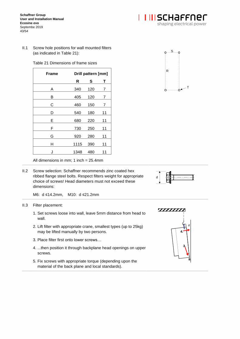
II.1 Screw hole positions for wall mounted filters
(as indicated in Table 21):
Table 21 Dimensions of frame sizes
Frame Drill pattern [mm]
R S T
A 340 120 7
B 405 120 7
C 460 150 7
D 540 180 11
E 680 220 11
F 730 250 11
G 920 280 11
H 1115 390 11
J 1348 480 11
All dimensions in mm; 1 inch = 25.4mm
II.2 Screw selection: Schaffner recommends zinc coated hex
ribbed flange steel bolts. Respect filters weight for appropriate
choice of screws! Head diameters must not exceed these
dimensions:
M6: d ≤14.2mm, M10: d ≤21.2mm
II.3 Filter placement:
1. Set screws loose into wall, leave 5mm distance from head to
wall.
2. Lift filter with appropriate crane, smallest types (up to 25kg)
may be lifted manually by two persons.
3. Place filter first onto lower screws…
4. ...then position it through backplane head openings on upper
screws.
5. Fix screws with appropriate torque (depending upon the
material of the back plane and local standards).
R
S
T
d
3.
4.

Schaffner Group
User and Installation Manual
Ecosine evo
Septembe 2019
44/54
Step 3: Wiring
III.1 Verify safe disconnection of all line side power.
Consult your local safety instructions.
III.2 Carefully connect protective earth (PE) wire to
adequate earth potential close to ecosine filter.
Use a wire diameter of equal or bigger size as foreseen
for line/load side power cables – according to your local
codes and safety instructions.
ECO
sin
e™
Dri
ve
>150mm
>150mm
>100mm
>100mm
III.3 Connect PE wire of ecosine filter
with appropriate cable lug to threaded stud.
| torque M5: 2.2 Nm
| torque M6: 4 Nm
| torque M8: 9 Nm
| torque M10: 19 Nm
| torque M12: 25 Nm
III.4 Connect ecosine load side terminals L1’, L2’, L3’ to respective motor drive or rectifier
inputs.
The third part of ecosine evo designation is a number contains three digits, i.e. FN 3440-11-113,
which indicates power terminal type.
See Table 1 for the recommended wire size and torque. Use stranded copper wire with a
temperature rating of 75°C or higher.
An optional workflow to connect power terminals without having the TDJ module in way is
applied. You might consider following these steps:
Connecting power terminals of passive harmonic filters ordered with TDJ module can be
facilitated by removing the trap disconnect wires while connecting the cables to the main
terminals. Afterwards the trap disconnect jumper cables need to be applied to the original position
again. Please follow these steps: Open terminals D1- D1’, D2- D2’and D3- D3’, remove the wires,
add main terminals and then fix wires on terminals D1- D1’, D2- D2’and D3- D3’ again. The
recommended torques given on the terminal label must be applied.
Remarks regarding IP 20 enclosure
1. To connect ecosine evo line and load side terminals, the fingure guard has to be removed
as a first step, and be installed again when the line and load side terminals are
connected. The screw thread and torque value for all the frame sizes are:
| Screw thread: M5 | Screw torque value: 4Nm
2. The metal finger guard for frame sizes E, F and G are equipped with grommets, whilst
figner guard H is equipped with stepped collars. Modify the stepped collars according to
the cable isolated diameter, 5-10mm margin is recommended to feed the cable easier.
Schaffner Group
User and Installation Manual
Ecosine evo
Septembe 2019
45/54
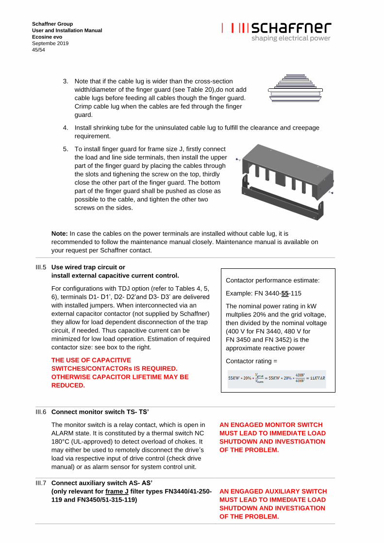
3. Note that if the cable lug is wider than the cross-section
width/diameter of the finger guard (see Table 20),do not add
cable lugs before feeding all cables though the finger guard.
Crimp cable lug when the cables are fed through the finger
guard.
4. Install shrinking tube for the uninsulated cable lug to fulfill the clearance and creepage
requirement.
5. To install finger guard for frame size J, firstly connect
the load and line side terminals, then install the upper
part of the finger guard by placing the cables through
the slots and tighening the screw on the top, thirdly
close the other part of the finger guard. The bottom
part of the finger guard shall be pushed as close as
possible to the cable, and tighten the other two
screws on the sides.
Note: In case the cables on the power terminals are installed without cable lug, it is
recommended to follow the maintenance manual closely. Maintenance manual is available on
your request per Schaffner contact.
III.5 Use wired trap circuit or
install external capacitive current control.
For configurations with TDJ option (refer to Tables 4, 5,
6), terminals D1- D1’, D2- D2’and D3- D3’ are delivered
with installed jumpers. When interconnected via an
external capacitor contactor (not supplied by Schaffner)
they allow for load dependent disconnection of the trap
circuit, if needed. Thus capacitive current can be
minimized for low load operation. Estimation of required
contactor size: see box to the right.
THE USE OF CAPACITIVE
SWITCHES/CONTACTORs IS REQUIRED.
OTHERWISE CAPACITOR LIFETIME MAY BE
REDUCED.
III.6 Connect monitor switch TS- TS’
The monitor switch is a relay contact, which is open in
ALARM state. It is constituted by a thermal switch NC
180°C (UL-approved) to detect overload of chokes. It
may either be used to remotely disconnect the drive’s
load via respective input of drive control (check drive
manual) or as alarm sensor for system control unit.
AN ENGAGED MONITOR SWITCH
MUST LEAD TO IMMEDIATE LOAD
SHUTDOWN AND INVESTIGATION
OF THE PROBLEM.
III.7 Connect auxiliary switch AS- AS’
(only relevant for frame J filter types FN3440/41-250-
119 and FN3450/51-315-119)
AN ENGAGED AUXILIARY SWITCH
MUST LEAD TO IMMEDIATE LOAD
SHUTDOWN AND INVESTIGATION
OF THE PROBLEM.
Contactor performance estimate:
Example: FN 3440-55-115
The nominal power rating in kW
multplies 20% and the grid voltage,
then divided by the nominal voltage
(400 V for FN 3440, 480 V for
FN 3450 and FN 3452) is the
approximate reactive power
Contactor rating =

Schaffner Group
User and Installation Manual
Ecosine evo
Septembe 2019
46/54
The auxiliary switch is a contact, which indicates state
of circuit breaker. It is closed under normal operation
(CB on) and is open in abnormal condition (CB off).
Abnormal condition can be a short circuit in the trap
capacitors, overcurrent in the trap circuit, too hot
ambient temperature or switch-off status in low load
condition (use of motor mechanism together with the
circuit breaker – check relevant section in user manual).
III.8 Connect ecosine line side terminals L1, L2, L3
to power input protection (current limiting fuses – see below).
IP 20 enclosure cable wiring please refer to the remarks for the load side cable wiring (III.4).
Note: For IP 20 filter versions the IP 20 finger guard must be installed in order to achieve
IP 20 protection. When the finger guard is not installed, Schaffner do not guarantee IP 20
protection.
III.9 Fuses
Ecosine evo passive harmonic filters need external over-current protection for compliance with
UL/cUL standard. Fuses and associated fuse holders must be UL listed and rated for 100kA
SCCR supplies. Table 22 and Table 23 show requested fuse current ratings for UL class J and,
where UL compliance is not mandatory, for IEC class gG. The fuse rating is independent of the
supply voltage.
A system with multiple ecosine evo filters paralleled for a high power load need each a separate 3-phase line side fuse block, corresponding to the respective filter and according to above table. The drive’s application manual may prescribe line-side fuse protection as well, which in this case either corresponds to the sum of the filter fuse ratings or, if lower, would request separate drive fuses at its input.
An application, having one ecosine filtering harmonics of several drives, requires in any case line side fuse protection of the drives as well as the correct filter protection according to Table 22 and Table 23.
DRIVE M
Ecosine 1
Ecosine 2
Ecosine 3
FUSE
FUSE
FUSE
Ecosine
DRIVE 1
DRIVE 2
DRIVE 3
FUSE
FUSE
FUSE
FUSE
M
M
M

Schaffner Group
User and Installation Manual
Ecosine evo
Septembe 2019
47/54
Table 22 Requested fuse current rating for UL class J and for IEC class gG
ecosine evo ecosine evo ecosine evo ecosine evo Fuse
class J Fuse
class gG
All FN 3440 All FN 3441 All FN 3450 All FN 3451 rated
A rated
A
FN 3450-1-110 FN 3451-1-110 2 2
FN 3440-1-110 FN 3441-1-110 2.5 2
FN 3450-2-110 FN 3451-2-110 4.5 4
FN 3440-2-110 FN 3441-2-110 FN 3450-4-112 FN 3451-4-112 8 8
FN 3440-4-112 FN 3441-4-112 FN 3450-6-112 FN 3451-6-112 10 10
FN 3440-6-112 FN 3441-6-112 FN 3450-8-112 FN 3451-8-112 15 10
FN 3440-8-112 FN 3441-8-112 FN 3450-11-112 FN 3451-11-112 20 16
FN 3440-11-113 FN 3441-11-113 FN 3450-15-113 FN 3451-15-113 25 20
FN 3440-15-113 FN 3441-15-113 FN 3450-19-113 FN 3451-19-113 35 35
FN 3440-19-113 FN 3441-19-113 FN 3450-22-113 FN 3451-22-113 40 35
FN 3440-22-113 FN 3441-22-113 FN 3450-30-115 FN 3451-30-115 50 50
FN 3440-30-115 FN 3441-30-115 FN 3450-37-115 FN 3451-37-115 75 63
FN 3440-37-115 FN 3441-37-115 FN 3450-45-115 FN 3451-45-115 80 80
FN 3440-45-115 FN 3441-45-115 FN 3450-55-115 FN 3451-55-115 100 100
FN 3440-55-115 FN 3441-55-115 FN 3450-75-115 FN 3451-75-115 150 125
FN 3440-75-115 FN 3441-75-115 FN 3450-90-116 FN 3451-90-116 175 160
FN 3440-90-116 FN 3441-90-116 FN 3450-110-118 FN 3451-110-118 200 200
FN 3440-110-118 FN 3441-110-118 FN 3450-132-118 FN 3451-132-118 250 224
FN 3440-132-118 FN 3441-132-118 FN 3450-160-118 FN 3451-160-118 300 250
FN 3440-160-118 FN 3441-160-118 FN 3450-200-118 FN 3451-200-118 350 300
FN 3440-200-118 FN 3441-200-118 FN 3450-250-118 FN 3451-250-118 400 400
FN 3440-250-119 FN 3441-250-119 FN 3450-315-119 FN 3451-315-119 600 600

Schaffner Group
User and Installation Manual
Ecosine evo
Septembe 2019
48/54
Table 23 Requested fuse current rating for UL calss J
ecosine evo type ecosine evo type ecosine evo type ecosine evo type Fuse class J
All FN 3442 ALL FN 3443 All FN 3452 All FN 3453 rated A
FN3442-1-110 FN3443-1-110 FN 3452-1-110 FN 3453-1-110 2
FN3442-2-110 FN3443-2-110 FN 3452-3-110 FN 3453-3-110 4
FN3442-4-112 FN3443-4-112 FN 3452-5-112 FN 3453-5-112 7
FN3442-6-112 FN3443-6-112 FN 3452-8-112 FN 3453-8-112 10
FN3442-8-112 FN3443-8-112 FN 3452-10-112 FN 3453-10-112 15
FN3442-12-112 FN3443-12-112 FN 3452-15-112 FN 3453-15-112 20
FN3442-16-113 FN3443-16-113 FN 3452-20-113 FN 3453-20-113 30
FN3442-20-113 FN3443-20-113 FN 3452-25-113 FN 3453-25-113 35
FN3442-24-113 FN3443-24-113 FN 3452-30-113 FN 3453-30-113 40
FN3442-32-115 FN3443-32-115 FN 3452-40-115 FN 3453-40-115 50
FN3442-40-115 FN3443-40-115 FN 3452-50-115 FN 3453-50-115 60
FN3442-48-115 FN3443-48-115 FN 3452-60-115 FN 3453-60-115 80
FN3442-60-115 FN3443-60-115 FN 3452-75-115 FN 3453-75-115 90
FN3442-80-115 FN3443-80-115 FN 3452-100-115 FN 3453-100-115 125
FN3442-100-116 FN3443-100-116 FN 3452-125-116 FN 3453-125-116 150
FN3442-120-116 FN3443-120-116 FN 3452-150-116 FN 3453-150-116 175
FN3442-160-118 FN3443-160-118 FN 3452-200-118 FN 3453-200-118 250
FN3442-200-118 FN3443-200-118 FN 3452-250-118 FN 3453-250-118 300
FN3442-240-118 FN3443-240-118 FN 3452-300-118 FN 3453-300-118 400
Schaffner Group
User and Installation Manual
Ecosine evo
Septembe 2019
49/54
9. Filter maintenance
Ecosine evo passive harmonic filters described in this manual are equipped with long life components that
ensure a satisfactory function for many years under normal operating conditions. Any operation under
extreme conditions such as over-temperatures, overvoltage situations, polluted environments etc. reduces
the life expectancy. Following maintenance recommendation will help maximizing filter lifetime.
Warnings:
High voltage potentials are involved in the operation of this product. Always remove line side
power before attempting to perform maintenance, and let ample time elapse for the
capacitors to discharge to safe levels (<42 V). Residual voltages are to be measured both
line to line and line to earth.
Line side power must be disconnected prior to replacement of any part.
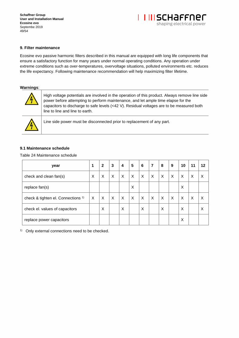
9.1 Maintenance schedule
Table 24 Maintenance schedule
year 1 2 3 4 5 6 7 8 9 10 11 12
check and clean fan(s) X X X X X X X X X X X X
replace fan(s) X X
check & tighten el. Connections 1) X X X X X X X X X X X X
check el. values of capacitors X X X X X X
replace power capacitors X
1) Only external connections need to be checked.
Schaffner Group
User and Installation Manual
Ecosine evo
Septembe 2019
50/54
9.2 Fan
Schaffner ecosine evo passive harmonic filters are reliable low maintenance products. Many products like
power supplies, inverters or motor drives utilize fans for forced cooling to minimize size and weight. Ecosine
filters are designed with a similar temperature management concept and therefore, fans may have to be
maintained and replaced in certain intervals to sustain the function and value of the product. Fans are 100%
field replaceable without the need to uninstall and disconnect the filter.
Forced cooling devices are needed for the operation of Schaffner ecosine evo passive harmonic filters up to
their nominal rating. Such cooling devices must be checked and cleaned regularly (if installed) to ensure
sufficient air flow at all times.
Note: increased audible noise is a typical indicator of a fan that needs maintenance or replacement also
outside of a maintenance schedule.
Before cleaning or replacing the cooling devices, make sure to consult the recommended maintenance
procedures and schedules of the supplier of the cooling device in use.
9.3 Power capacitors
The power capacitors supplied with the filter modules are high quality components with an expected life time
of up to 100’000 hours (11 years). Nevertheless, their useful service life can be shortened by electrical or
thermal stress beyond their specification.
Power capacitor damage may also be caused by severe abnormal supply voltage peaks (i.e. lightning –
depending upon system protection), but may only be recognizable through the measurement of line side
harmonics distortion. This may be checked with a modern energy meter or by regular checkup with a power
quality analyzer. According to the above considerations, a 2 year inspection interval is advisable.
Note: an inspection should as well be performed after extreme overvoltage situations in the system.
Note: Storage of capacitors
Up to 3 years-long storage, electrolitic capacitors can be operated without any restriction and the nominal
voltage can be applied without any preliminary preparation. System reliability and life-time expectancy are not
affected.
On the other side, a longer ( >3 yrs) storage of electrolitic capacitors without applying any voltage can
weaken the dielectric properties because of disslution processes. The electrolitic solution is aggressive and it
can affect and weaken the dielectric in the timeframe between production and product commissioning. The
weak points are responsible for the higher leakage current shortly after the device turn-on on site.
The residual current of electrolitic capacitors depends upon time, voltage and temperature. The residual
current increases after long storage without applying voltage.
The amplitude of resulting residual current during unit commissioning can be up to 10 times larger on short
term. The capacitor’s residual current assumes the typical expected value at steady state for nominal voltage.
During comissioning after long storage, it is recommended to restore the dielectric characteristics by applying
voltage progressively and with respect to the time frame the filters have been stored.
9.4 Electrical connections
Depending upon the environment and application, electrical connections, in particular threaded bolts and
nuts, can degrade over time by means of losing their initial tightening torque. This holds true not only for the
filter, but for any such joint within an electrical installation.
Therefore, Schaffner recommends to check and tighten all electrical connections on the occasion of a regular
scheduled maintenance of the entire device that incorporates the filter.

Schaffner Group
User and Installation Manual
Ecosine evo
Septembe 2019
51/54
Check of internal connections within the filters is not needed or should be conducted by a Schaffner service
representative.

Schaffner Group
User and Installation Manual
Ecosine evo
Septembe 2019
52/54
10 Trap circuit disconnect
The trap circuit disconnect feature is a modular option for the purpose of reducing the capacitive current
during low load operation, if needed. With permanently connected trap circuit, cosφ vs. load shows following
characteristics:
When the trap circuit is disconnected, cos(phi) returns to ~0.98. At the same time, the THID will increase.
This may be negligible, since absolute values are low due to reduced load power.
Needed external components (not part of ecosine filter) or system functions for fully automated capacitive
current control:
| Motor load (power factor) monitoring device
| Capacitor contactor
A reduced load system status may be available as system controller output signal. In this case, only adequate
driving of capacitor contactor has to be assured.
Note: It is necessary to take into account overall concept of power factor correction. A system PFC correction
unit with large capacitor banks may become obsolete or massively reduced, when harmonic filters are
installed. In such cases it may not be necessary to install trap circuit disconnect functions.
Recommended settings:
Schaffner recommends to engage and disengage the trap circuit disconnect at following load levels:
Trap circuit status Proposed load level
Disconnect When load level drops under 10–15%
Connect When load level rises above 20–25%

Schaffner Group
User and Installation Manual
Ecosine evo
Septembe 2019
53/54
11. Troubleshooting
Schaffner Ecosine harmonic filters are high quality products and have undergone rigorous testing and
qualification procedures. Every unit runs through suitable tests in our ISO 9001:2000 factories. Due to this
reason no major issues need to be expected if the filter is installed, operated, and maintained as described in
this document.
In the unlikely event of a problem, please contact your local Schaffner partner for assistance.

Schaffner Group
User and Installation Manual
Ecosine evo
Septembe 2019
54/54
Disclaimer
This document has been carefully checked. However, Schaffner does not assume any liability for errors or
inaccuracies. Published specifications are subject to change without notice. Product suitability for an area of
application must ultimately be determined by the customer. In all cases, products must never be operated
outside their published specifications. Schaffner does not guarantee the availability of all published products.
Latest publications and a complete disclaimer can be downloaded from the Schaffner website. All trademarks
recognized.