user guide 3g video surveillance
DESCRIPTION
User Guide 3G Video SurveillanceTRANSCRIPT

Before purchasing or installing a SIM card into
the camera unit, it is important to select the best
3G network provider in the area where the
camera will be installed.
This can be done simply using your own 3G
mobile handset.*
Instruction:
1. Navigate to the phone “Network” settings.
2. Change the “Operator selection” setting
from “Automatic” to “Manual”.
This forces the handset to search for all
available network coverage, and may take a
few minutes.
3. The list of all available network operators
will be displayed on the phone’s screen.
4. Note down the name of one or more
network operator that provide 3G coverage
from the list (they are usually displayed
with a 3G sign next to their name).
5. Cancel the setting process on the handset
to maintain the phone’s original network
settings.
Note: Only purchase 3G SIM cards from the 3G
networks listed, whilst choosing one with a
suitable price plan.
BiBCOM also offers the best price plan available,
being specifically tailored to the customer
requirements for using the 3G surveillance
system. Currently this offer is only available for
3G SIM Cards using BT network.
Note: Remember to disable video and voice mail
facilities on the SIM card before installing it into
the camera unit.
The above steps are very similar on most phones;
however, please refer to their user manual for
details.
Example: Searching for available 3G network
using Nokia N95 handset:
1. Select: “ Menu -> Settings -> Phone -> Network”
2. Set: “Operator Selection” to “Manual”
3. Wait until the list of all available networks are displayed.
Ref: DOC-1008463
Select a suitable 3G SIM
Card for the Camera Unit
*Phone must be compatible with country of use as the 3G frequency may vary.

3G CAMERA UNIT - BASIC USER GUIDE
Starting the 3G Camera Unit
• Carefully remove the rear cover of the Camera Unit
• Lift the sticky tape and rubber shroud, and remove the battery to reveal the SIM card holder
• Insert a suitable SIM card to the 3G camera unit
• Replace the battery and rubber shroud
• Start the 3G camera unit by connecting the mains power supply and wait for a minimum of 3
minutes for the camera to activate.
Receiving live video and audio
• Make a video call from your 3G mobile phone to the camera unit to receive back live video
and audio from the camera location. The camera will automatically answer your call.
Receiving live audio only
• Make a voice call to the camera unit.
SMS Command for receiving still pictures
• Send an SMS as follows: 00000 snap
For a guide to full functionality please consult Tables A and B inside the User Manual.

1
Table of Contents
Section One: Setting up the SIM card ………………………………………………………………………2
Section Two: Removing and adding a SIM card to the Camera Unit .…..……….…………..4
Section Three: Remote setting of the Camera Unit using SMS …………………………………5
Section Four: Remote setting examples……………………………………………………………………9
Section Five: Recording an event using your phone………………………………..……………...13
Section Six: Important notes & FAQs …………………………………………………….……………....14

2
Section One Setting up the SIM card
Setting up the SIM card
PLEASE DO NOT INSERT THE BATTERY
INTO THE CAMERA UNIT UNTIL YOU
FOLLOW THE INSTRUCTION ON THIS
PAGE.
It is very important to follow these
instructions to install a 3G SIM Card to
work with the Camera Unit in order not to
damage it. Any Damage incurred through
incorrect use will not be covered by the
warranty.
You can install either a contractual SIM
card or Pay-As-You-Go (i.e. PAYG) SIM card
into the camera unit. Ensure following
settings are applied on the SIM card by
contacting the network operator for the
SIM card.
1. Ensure the SIM card is 3G, then insert it
into your 3G phone (i.e. Phone A).
2. Turn ON the phone, and check on the
screen to see if there is a 3G sign on
the signal strength side. If 3G is not
shown, then you do not have 3G
coverage in that area, or you may need
to force your phone to only use a 3G
network (please refer to your phones
handbook to see how you can force
your phone to use the UMTS or 3G
network).
3. If the SIM card is not registered under
your name, please contact the network
operator in order to register the SIM
card under your name.
4. Ensure the SIM card is topped up with
some credit. You may use a SIM card
that is on a monthly contractual
payment. Some credit is required when
the SIM card is sending SMS reports or
making a call back to you upon request
(Refer to “Important Notes” on page 11
of user guide).
5. Now use Phone A in the area that the
Camera Unit is going to be installed,
and check the 3G Signal strength on
the Phone. This is to ensure your SIM
card is able to make or receive video
calls when it is installed into the
Camera Unit.
6. Make a VIDEO call (not voice call) from
phone A to another 3G mobile phone,
to ensure Video call capability is
activated on this SIM card.
7. Answer the call on the other phone, to
ensure the video call is possible. Then
disconnect the call by pressing the red
button after a few seconds. However
keep an eye on the phone screen, to
see if there is any notification pops up
on the screen.
8. Some SIM cards are set up to show the
remaining credit on the SIM card after
any call made by the SIM card. This is
set up by the network operator, which
is not required on the Camera unit.
Therefore you need to contact the
network operator to disable this popup
notification.
9. Contact the service provider for the
SIM card using Phone A and request to
disable VIDEO MESSAGING & VOICE
MESSAGING facilities on the SIM Card.
DO NOT DISABLE VIDEO CALLING
FACILITIES. This is required to prevent
leaving Video or Voice messages on the
SIM card when the camera unit is
turned off. This might take from 5
minutes up to 24 hours to be applied
on the SIM card by different network
providers. This is also to prevent others
to contact this SIM card and leave
unnecessary messages.

3
Section Two Setting up the SIM card
10. Wait as long as necessary and use
another phone (i.e. Phone B) to make a
video call to phone A. Do not answer
the call and let it ring ensuring that the
call does not divert to the video
answering service. If it diverts to the
video answering service, then your
video messaging facility is still active,
and you cannot use the SIM card for
the Camera Unit yet.
11. Repeat the above and make a Voice
call to the Camera Unit, and ensure the
call is not diverted to the Voice mail
answering service.
12. If using a contract SIM in the camera
unit, ensure that you can make video
calls on it at the location, where the
camera unit will be installed. Some
network providers will require your
authorisation to set this up, especially
if you are going to contact it from
abroad.

4
Section Two Removing and adding a SIM card to the Camera Unit
Removing and adding a SIM card to the Camera Unit
The camera unit may already be fitted
with a UK network SIM, if so, please
remove this SIM following the procedure
below.
1. If the camera unit is fitted in an
enclosure, please refer to the
separate “Installation Instruction” on
how to open the enclosure then
follow the instructions below to
change the SIM card.
2. Ensure power is NOT connected to
the camera unit.
3. Insert the tested SIM.
4. Insert the battery.
5. Repack the rubber shroud on the
camera unit.
6. Turn on the Power to the Camera
Unit. If using 12V DC power supply,
then wire the power leads to the
provided socket, and ensure you
connect the positive wire to + (or red
side) and negative wire to – (or black
side) as marked.
7. It will take up to 5 minutes for the
camera unit to power up.
8. Test the camera unit by making a
video call to it from another 3G
phone.
9. Alter the settings on the camera unit
by using SMS commands explained in
the user’s guide, using the default
password.
10. After completing the setting, ensure
it is all setup correctly by requesting
a report from the camera unit (using
SMS command), and also making
another video call from an
authorised mobile phone number.
Note: As default, when using the
camera unit for the first time, prior
to changing its settings, it is set to
“public access”, allowing anyone to
make a video call to the Camera
Unit. Therefore you must ensure to
modify this setting if you wish
restricted number of people to
access the camera unit.

5
Section Three Remote setting of the Camera Unit using SMS
Remote setting commands using SMS
The remote setting SMS message contains three parts: A, B and C as shown in the table below:
Table A: Commands for camera unit settings
A
(Current
Pin ID)
B
(Commands)
(Capital or small
letters)
C (Setting
Values)
Description
1 00000 ADDCALL 07912345678 To add a new number (i.e. 07912345678) to the
caller’s list.
2 00000 DELCALL 07912345678 To delete a number (i.e. 07912345678) from the
caller’s list.
3 00000 ACCTYPE PUBLIC (or)
PRIVATE
Set the access type of the camera unit to Public or
Private
4 00000 REPORT Request a full report of the camera unit settings
5 00000 OCDSET 2 (or) 4 (or) 6 Setting the out-going call duration from the camera
unit to 2, 4 or 6 minutes (if the camera unit is paired
with a sensor.
6 00000 INRING 0/1/2 Setting the camera unit to answer incoming calls
after 0/1/2 rings
7 00000 SETTD 17:00
DD/MM/YYYY
Sets current time and date
8 00000 AUTANS YES/NO Enable/disable Auto-Answering the calls by camera
unit.
9 00000 DTIMER 14:30 Daily time setup for the camera unit to restart using
the 24 hrs clock format
10 00000 WSMSC Your SMS
Content (<=160
characters)
Customise the SMS content that is sent to user
11 00000 RSMSC Read the SMS content that is sent to user
12 00000 RESTART Restart the camera unit
13 00000 DAREP ON/OFF Daily activity (Total incoming/outgoing calls/SMS
report)
14 00000 SETSIR ON/OFF/10 Sets sensor interval Respond time. This command is
valid only if the camera unit is paired with a sensor
15 00000 HELP Gets list of SMS commands.
16 00000 SETPIN 1gh45 Alter the Pin code of SMS commands from 00000 to
1gh45
6
Section Three Remote setting of the Camera Unit using SMS
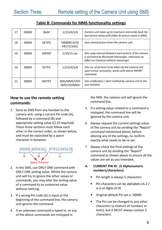
Table B: Commands for MMS functionality settings
17 00000 SNAP 1/2/3/4/5/6 Camera unit takes up to 6 pictures and sends back the
last picture along with folder & picture name in MMS.
18 00000 GETPIC F#080813(10)
P#172234(1)
Gets stored picture from the camera unit.
19 00000 SNPINT 5/10/15 sec Sets snap interval between each picture, if the camera
is activated by Bluetooth Messenger, otherwise no
effect on Cameras without messenger.
20 00000 SETPIC 1/2/3/4/5/6 Sets no. of pictures to be taken by the camera unit
upon sensor activation, works with above SNPINT
command.
21 00000 NOTIFY SMS/MMS/VDO
SMS/VDOMMS
Sets notification / alert method by camera unit to the
user handset.
How to use the remote setting
commands:
1. Send an SMS from any handset to the
camera unit, using a correct Pin code (A),
followed by a command (B) and
appropriate setting value (C) (if required).
These three sections must follow each
other in the correct order, as shown below,
and must be separated by a space
character in between.
2. In the SMS, use ONLY ONE command with
ONLY ONE setting value. Whilst the camera
unit will try to ignore the other values or
commands, you may alter the setting value
of a command to an undesired value
without noticing.
3. If a wrong Pin code (A) is input at the
beginning of the command line, the camera
unit ignores the command.
4. If an unknown command is typed in, or any
of the above commands are mistyped in
the SMS, the camera unit will ignore the
command line.
5. If a setting value related to a command is
mistyped, the command line will be
ignored by the camera unit.
6. Always request the current settings value
of the camera unit by sending the “Report”
command mentioned above, before
altering any of the settings, to confirm
exactly what needs to be re-set.
7. Always check the final settings of the
camera unit by sending the “Report”
command as shown above to ensure all the
values are set as you intended.
A. CURRENT PIN ID: (5 Alphanumeric
numbers/characters)
• Pin length is always 5 characters
• Pin characters can be alphabets (A-Z /
a-z) or digits (0-9)
• Original default Pin set is 00000
• The Pin can be changed to any other
characters (a mixture of numbers or
texts), but it MUST always contain 5
characters.
00000 ADDCALL 07912345678
A B C
Space character

7
Section Three Remote setting of the Camera Unit using SMS
B. COMMANDS: (6-9 characters)
The commands are not case sensitive so
can be in capital or small letters.
B.1. ADDCALL: Add Caller: Adds phone
number to the caller’s list of the
camera unit
B.2. DELCALL: Delete Caller: Deletes a
phone number from the camera unit’s
caller list
B.3. ACCTYPE: Sets Access Type on the
camera unit to either Private or Public
B.4. REPORT: To request a full Report of all
the critical settings for the camera unit.
B.5. OCDSET: Outgoing Call Duration Setup:
limits the duration of the outgoing calls
made from the camera unit to 2, 4 or 6
minutes.
B.6. INRING: Number of Incoming Rings: To
set the number of rings for incoming
calls. If you use INRING 0, the camera
unit will try to answer the incoming
calls (if the caller’s number is
authenticated) straight away without
any ring; INRING 1, after 1 ring, etc.
B.7. SETTD: To change the current Settings
for the Time and Date.
Note1: please include a space between
time and date in the SMS command,
otherwise camera unit time will not be
set.
Note2: If the camera unit has been
without power for a long period of time
(more than a few days), then the time
and date may reset therefore should
be checked and corrected using SETTD.
B.8. AUTANS: Enable or disable Auto
Answering: To enable or disable auto
answering the incoming calls (voice &
video) by the camera unit.
B.9. DTIMER: Daily Timer: Sets the camera
unit to re-boot at a certain time on a
daily basis
B.10. WSMSC: Write SMS Content: The default
SMS Message that is sent to carers’ in
the event that they are unavailable to
take any calls is: “Urgent: An emergency
call was made, please take action.”
B.11. RSMSC: Read SMS Content: This
command is used to check the current
content set using the WSMSC command,
above.
B.12. RESTART: Restart the camera unit
B.13. DAREP: Daily Activity Report: Enable or
disable the camera unit to report the
total incoming/outgoing calls/SMS
B.14. SETSIR: Set Sensor Interval
Response time. After the first alert,
the camera unit will make a
video/voice call or SMS then wait
for specified time before next call.
This command is valid only if the
camera unit is paired with a sensor
(except push button messenger).
B.15. HELP: Request list of all SMS
commands related to MMS.
B.16. SETPIN: Sets new Pin as defined by
the user
B.17. SNAP: Request Snaps from Camera
Unit.
B.18. GET PICture: Request picture from
Camera Unit.
B.19. SNPINT: SNap Picture INTerval:
Camera Unit waits for specified
interval before taking next snap.
B.20. SETPIC: SET PICture: Sets no. of
pictures to be taken by Camera Unit
upon sensor activation.
B.21. NOTIFY: Notification / Alert method
from Camera Unit.

8
Section Three Remote setting of the Camera Unit using SMS
C. SETTING VALUES:
C.1. ADDCALL: Input an appropriate phone
number with this command to add a
new number into the callers list of the
camera unit. You must input the number
starts with 0 (without any country code).
The camera unit would automatically
answer the call made from this number,
even from abroad.
C.2. DELCALL: Input an appropriate phone
number with this command. The
number you input here, must match the
number that was already defined as
access number within the camera unit. If
the number matches, it will be removed
from the list, otherwise it will have no
effect.
C.3. ACCTYPE: Input PUBLIC or PRIVATE
along with this command.
C.4. REPORT: No setting value is input with
this command.
C.5. OCDSET: Only input 2 or 4 or 6, to alter
the maximum Outgoing Call Duration to
2 minutes, 4 minutes or 6 minutes
accordingly.
C.6. INRING: Only input 0 or 1 or 2 for this
command
C.7. SETTD: Input the current time and date
(eg. 17:00 03/05/2008)
C.8. AUTANS: Input YES or NO
C.9. DTIMER: Input a correct time (in
between 00:00 to 23:59) along with
DTIMER command. This is to set a daily
restart time of the camera unit to this
new time.
C.10. WSMSC: Input the appropriate SMS
content along with this command.
C.11. RSMSC: No input is needed for this
command
C.12. RESTART: No input is needed for this
command
C.13. DAREP: Input ON or OFF
C.14. SETSIR: Input ON or OFF or time
between 5mins and 30mins. This
command is valid if the camera unit is
paired with a sensor (except push
button messenger).
C.15. HELP: There is no setting value for HELP
command.
C.16. SETPIN: To alter the Pin code for the
SMS commands, input a new Pin ID
value along with SETPIN command. This
new value must contain 5 characters
ONLY, and can be a combination of
numbers or texts.
C.17. SNAP: Input no. of pictures (in
between 1 to 6), to be taken by
camera unit, along with SNAP.
C.18. GETPIC: Input folder & picture name
along with GETPIC.
C.19. SNPINT: Input snap interval value ( 5
/ 10 / 15 sec) along with SNPINT
C.20. SETPIC: Input no. of pictures (in
between 1 to 6), to be taken by
camera unit upon sensor activation,
along with SETPIC.
C.21. NOTIFY: Input notification / alert
method
(SMS/MMS/VDOSMS/VDOMMS)
along with NOTIFY.

9
AccTyp: Rest
3GSig: 7
BatLev: 7
Access# (4):
07912345678
07987654321
07812345678
07801234567
Rings: 1
OCDSet: 2min
DTimer: 14:30 -D
TimeDate: 17:00 03/05/2008
Notify: VDOSMS
Fig. 2
Section Three Remote setting examples
Remote Setting Examples:
1. To request the setting status of the
camera unit:
Send the SMS shown in Fig 1. from
any phone to the camera unit. The
original PIN ID set for the camera unit
is 00000 that is used at the beginning
of the SMS as shown here.
Note: You can change this PIN CODE
to a unique value that you would only
know as explained in section 4 below.
In response the camera unit would
send an SMS back to the users phone.
This shows the setting status (i.e.
values) of the camera unit as shown
in Fig. 2. In this example, the SMS
shows the current setting of the
camera unit as follow:
1.1. AccTyp: Rest
This means the access type is
Restricted.
1.2. 3GSig: 7
3G signal strength is 5, which is around
70%.
Note: Full 3G signal is measured on
scale of 1 to 7 (i.e. 1 means 14% & 7
means 100% 3G signal strength). 3G
signal levels of 0 or 1 are not good for
video calls. In this case, it is better to
move the camera unit where it is
located, or use a different Simcard
from a different network provider.
Contact your supplier for more
information.
1.3. BatLev: 7
Battery level is 7 (i.e. 100%)
Note: The battery level is measured on
scale of 1 to 7 (i.e. 1 means 14% & 7
means 100% of the battery left).
1.4. Access# (4):
07912345678
07987654321
07812345678
07801234567
This is the caller’s numbers that the
camera unit automatically answers the
video and voice calls made from them.
The number in brackets indicates the
total number of callers in the list.
Note1: If there are more than one
number in the list, the order of the
numbers in this list is based on which
one is defined first (i.e. they are not
sorted by numbers etc).
Note2: You can define more than four
numbers in the callers list, only the
first four numbers will be listed in the
report, due to the limited number of
characters allowed in an SMS message.
The total number of authorised callers
is shown in the bracket.
00000 REPORT
Fig. 1

10
Section Three Remote setting of the Camera Unit using SMS
Note3: If the Falcon SW200 system is
used with the call-back functionality
(ie, using sensor/messenger) then only
the first four numbers in the caller list
will be used by the “multilevel
reassurance system” (as described in
page 6)
1.5. Rings: 1
This means the camera unit will
answer the incoming calls after one
ring.
1.6. OCDSet:2min
This means the outgoing call from the
camera unit will be limited to 2mins
1.7. DTimer: 14:30 –D
This means the camera unit will reboot
at 14:30 on a daily basis. It may take
up to five minutes to the system to
start up and ready to use.
1.8. TimeDate: 17:00 03/05/2008
This means the current time and date
on the camera unit is 17:00
03/05/2008
1.9. Notify: VDOSMS
This means the camera unit will notify
the user by video and SMS (if video
fails) when the sensor is triggered.
2. Remove a caller from the caller list:
Send the SMS shown in Fig 3.
The camera unit upon receiving this SMS
will delete the third number (shown in
Fig 2) from its caller list. No reply is sent
to the user if the number doesn’t exist,
while the camera unit simply ignores the
SMS.
3. Add new number to the caller list:
Send the SMS shown in Fig 4.
The camera unit upon receiving this SMS
will add the above number at the end of
its caller list.
4. Set Access type to public
Send the SMS shown in Fig 5 to set the
Access type of the camera unit to public.
Changing the Access type of the camera
unit to Public means the camera unit
would answer the incoming calls to
anyone who dials to the camera unit.
This does not remove the caller’s list
from the camera unit. The caller’s list
remains the same if you change the
Access type from Public to Private in
future.
Note: It is recommended to always set
the Access type to Private, except where
privacy intrusion is not an issue where
you are installing the camera unit.
5. Check the setting status
Note: It is recommended to check the
camera unit status (settings) once more
when you finished setting up its
parameters by sending a ‘report’ SMS
command, as shown in Fig.1.
00000 DELCALL 07843216788
Fig. 3
00000 ADDCALL 07988776655
Fig. 4
00000 ACCTYPE PUBLIC
Fig. 5

11
Section Three Remote setting of the Camera Unit using SMS
6. Setting Time & Date
If the camera unit is left out of power for
a very long period, when it restarts, it
will set the time and date of the unit to a
random value. Therefore it is
recommended to use this command to
alter the date and time on the unit to a
correct value. Always input time first (in
24 hour format), then you MUST input
the correct date, otherwise the camera
unit will not accept the command. This
shown in Fig. 6.
7. Setting Daily Re-start option for the
camera unit.
By Using DTIMER command, you can set
a time to the camera unit to re-boot
every day. This is a good practice (but
not necessary), to allow the memory of
the camera unit to re-fresh everyday -
like any other device having a
microprocessor such as a computer etc.
To set a daily re-start option on the
camera unit use DTIMER command as
shown in Fig 7.
The time set in the above command
must be in 24 hour format.
You can remove DTIMER setting by using
RTIMER command as shown in Fig 8.
If the DTimer is not set at all, or it is
removed by using RTimer, you will not
see any value set for DTimer when you
request a report from the camera unit.
8. Request Snap
Send an SMS shown in Fig 9 to request
the last picture taken. The camera unit
will take 4 pictures, which will be stored
in its memory, and send you back the
last picture along with folder & picture
name, as shown in Fig 10.
Fig. 7
00000 DTIMER 03:10
Fig.9
00000 SNAP 4
Fig. 6
00000 SETTD 09:18 27/03/2008
Fig. 8
00000 RTIMER
To +4407012345678
Subject MMS from Camera
Folder Name: 080813(6)
Pictures Taken: #132245(1).jpg
#132250(2).jpg #132255(3).jpg
#132300(3).jpg
Fig. 10

12
Section Three Remote setting of the Camera Unit using SMS
9. Request stored picture
Send an SMS shown in Fig 11 to get the
stored picture from camera unit.
10. Set Snap Interval
Send an SMS shown in Fig 12 to set the
Snap interval to 5 seconds. Camera unit
will take requested pictures for every 5
seconds.
11. Set Number of pictures
Send an SMS shown in Fig 13 to set the no.
of pictures to 4. Upon sensor activation,
camera unit will take 4 pictures and send
last picture to first caller in the caller list.
12. Set Notification method
Send an SMS shown in Fig 14 to set the
notification / alert method. Upon sensor
activation, camera unit will make video call
and send SMS, if video call fails.
13. Request list of commands
Send an SMS shown in Fig 15 to request
list commands from camera unit. You will
receive the list of SMS commands.
14. Set new PIN
Send the SMS shown in Fig 16 to set the
Pin ID for remote SMS setting to a new
value: 12ua5
This changes the old Pin code (i.e.
00000) to the new Pin code (i.e. 12ua5).
The Pin code characters are not case
sensitive; therefore in future you can use
either lower or upper case Pin ID to
communicate with your camera unit.
Note: You should remember that from
now on you have to use 12ua5 as the Pin
number to communicate (i.e. send
commands etc) to your camera unit, as
shown in the following examples
Fig. 11
00000 GETPIC F#080813(6)
P#132245(3)
00000 SETPIC 4
Fig. 13
00000 NOTIFY VDOSMS
Fig. 14
00000 HELP
Fig. 15
00000 SNPINT 5
Fig. 12
00000 SETPIN 12ua5
Fig. 16

13
Section Four Recording an event using your phone
Recording an event using your phone
Recording an event using your phone:
You can directly connect your mobile
phone to a DVR or any other digital
recording media, then make a video call to
be able to record the events whenever you
wish. Please check with your retailer to see
if your mobile phone is suitable for this
purpose.
Alternatively, you can still record a short
length of the event either in voice or video
format by using Callback command as
explained in the previous section. To do
this you must enable video or voice
messaging functionality on your mobile
handset. Then request a video or voice call
back from the camera unit using
“CallBack” command. When you receive
the call from the camera unit, simply reject
the call. This way you will direct the
incoming call to your video or voice
mailbox on your network.
The Camera unit can then send live video
or voice data into your message boxes. The
duration of the message is dependent to
your network provider and can vary in
between 1 to 5 minutes for voice or video
calls. You can check this with your network
provider.
If you wish to record more than this
period, then you would need to contact
your retailer to supply a recording device.
Very important Note:
You must not enable Voice or Video
messaging on the SIM card used within
the Camera Unit. Otherwise anyone can
leave message on the SIM card on the
camera unit that can jeopardise the
operation of the unit.

14
Section Five Important notes & FAQs
Important Notes:
1. It is recommended to top up the credit
on the SIM Card in the camera unit
regularly, such as every month, or
every 3 months. Depend how many
times to you request a Report from the
camera unit.
Each time that the Camera unit sends
an SMS to a mobile handset, it reduces
the credit allocated for its SIM card. If
you do not receive any SMS from the
Camera Unit, it means there is no
credit available in the unit to be able to
send out SMSs. This may also effect
the performance of the Camera Units
operation. Any video calls made to the
unit does not affect the credit of the
SIM card in the Camera Unit. However
this might be different with some non-
UK network providers. Please check
this with the Network providers for the
SIM Card used in the Camera Unit,
where you are using it.
2. Make sure to alter the Pin code from
00000 to something that only you
know. Keep this code safe and secure
for your future reference.
FAQs:
1. I make a video call from my mobile
phone, but get the following message:
“Video call is not supported by the
Network”
You do not have 3G coverage in the
area where you are using your mobile
phone for video calls. You can instead,
use voice call to hear what is
happening around the Camera Unit, or
try to find a different location, where
you can see the “3G” sign on the
screen of your mobile phone.
2. I make a video call from my mobile
phone, but get the following message:
“Video call is not supported by the
other Network”
There is a problem with the 3G
network provider where you have
located your Camera Unit. You may
contact the network provider to clarify
the situation. If the problem persists,
you may contact your supplier to give
you an alternative Camera Unit with a
different SIM Card in it (using a
different Network Provider), that has
got a better 3G coverage in the area.
However you have always have a
choice of making a voice call instead to
hear what is happening around your
Camera Unit. You should not attempt
to open up the electronics inside of the
Camera Unit, as it can damage the unit
and can also be hazardous to health.
3. I make a video call from my mobile
phone, but get the following message:
“Receiving video images” but it
doesn’t show the video.
This might be related to the network
coverage, or your camera unit. Try to
remotely re-start the covert camera
unit using SMS (explained in Appendix
A). If the problem still exists, then you
must contact the shop or your retailer
to send the equipment back to be
repaired.

15

16
Ref: RS-1009715
Reference RS-1009715
Name User Guide
Author RS
Description User guide and SMS command for 3G camera setup.

Ref: RS-1009715
Introduction:
This document explains working principle of CX611MCH-V 3G Camera
Features:
1. Answers incoming audio and video calls
2. Remote control settings ( Refer Table 1)
3. Restarts every 24 hours
4. ON/OFF switch
5. Low battery notifications. ( Refer Table 2)
6. LED indicator for low signal strength, low battery, call failed etc.
7. Network mode toggle (Refer Table 1)
8. Sends SMS notification on alert (wired sensor) up to 4 callers in the list.

Ref: RS-1009715
LED Indicators:
Flashing:
1. If unauthorized caller, LED flashes 5 times every 1 second (Medium Flash)
2. If low signal strength, LED flashes 5 times every 0.5 second (Fast flash)
3. 2 flashes during switching OFF the phone. (Slow Flash)
4. LED ON during active calls
ON/OFF switch
1. Press and hold the ON/OFF switch for 4 seconds to switch OFF the phone.
2. Press ON/OFF switch to check phone status, flashes LED for 5 seconds (Fast flash) if low
signal otherwise keeps LED ON for 5 seconds.
Wired Sensor
1. Sends SMS notification up to 4 callers in the list.
2. Flashes (Fast Flash) if no callers in the list.

Ref: RS-1009715
SMS commands
No PIN First command Second command Description
1 00000 ADDCALL 07012345678 Adds this number to the caller list
2 00000 DELCALL 07012345678 Deletes this number form caller list
3 00000 SETPIN 12345 Set new pin to 12345
4 00000 ACCTYPE PRIVATE/PUBLIC Sets access type to public or private. Default
set to Public mode.
5 00000 RESTART Restarts camera unit.
6 00000 REPORT Sends following info.
Ex:
3G Signal: 100%
Battery: 100%
Access Type: Public
Access#(2):
07012345678
07987654321.
Serial Number#: 35671234567890 1
7 00000 SNAP Takes snapshot and sends it back via SMS
8 00000 TOGGNW Toggles network between dual mode and
3G. Note: This is for administrator use only.
Table 1
Notifications
Low Battery Sends low battery notification once remaining battery gets to 25%.
Ex: Attention: 25% Battery remaining on the camera unit. Please recharge the battery.
Low Memory Sends low memory notification once internal remaining memory gets to
30% or external memory (Memory card) gets to 10%.
Ex: Attention: Memory remaining on camera unit is 23%. Please delete some files or replace memory
card.
Table 2