user guide terrameter ls - · pdf fileabem terrameter ls abem warrants each instrument...
TRANSCRIPT

Instruction Manual
Terrameter LS
ABEM Product Number 33 3000 95
ABEM 2016-03-14, based on release 1.15.4

ABEM Terrameter LS

ABEM Terrameter LS
Thank you for choosing ABEM Terrameter LS
ABEM Terrameter LS1 is a state-of-the-art data acquisition system for self potential (SP),
resistivity and time-domain induced polarization (IP). The instrument has been carefully
checked at all stages of production and is thoroughly tested before leaving the factory. It will
provide many years of satisfactory service if handled and maintained according to the
instructions given in this manual.
ABEM will be pleased to receive occasional reports from you concerning the use and
experience of the equipment. We also welcome your comments on the contents and usefulness
of this manual. In all communication with ABEM be sure to include the instrument types and
serial numbers. Contact details:
Address: ABEM Instrument AB, Löfströms Allé 6A, S-172 66 Sundbyberg, Sweden.
Phone number: +46 8 564 88 300
E-mail: [email protected] or, for technical questions, [email protected]
Information about ABEM´s product range is available on Internet: www.abem.se
In general, e-mail correspondence gives the fastest response.
In view of our policy of progressive development, we reserve the right to alter specifications
without prior notice.
Note! It is important that you as the user of the instrument notify
ABEM about your name and address. This allows us to keep
you updated with important information, upgrades of the
built-in software and documentation. Please send your name
and address directly to ABEM, utilise the Warranty
Registration Card delivered along with the instrument.
Information in this document is subject to change without notice and constitutes no commitment
by ABEM Instrument AB.
ABEM Instrument AB takes no responsibility for errors in the document or problems that may
arise from the use of this text.
© Copyright 2016 ABEM Instrument AB. All rights reserved.
1 LS can be read as an abbreviation for Lund System, as it has built-in Lund Imaging System capability.

ABEM Terrameter LS
ABEM warrants each instrument manufactured by them to
be free from defects in material and workmanship.
ABEM's liability under this warranty is limited in
accordance with the terms of General Conditions for the
Supply of Mechanical, Electrical and Associated Electronic
Products (ORGALIME). It covers the servicing and
adjusting of any defective parts (except tubes, transistors,
fuses and batteries).
The Warranty is effective for twenty-four (24) months after
the date of Bill of Lading or other delivery document issued
to the original purchaser, provided that the instrument is
returned carriage paid to ABEM, and is shown to ABEM's
satisfaction to be defective. If misuse or abnormal
conditions have caused the fault, repairs will be invoiced at
cost.
Warranty
Stockholm, 2016
Kjell Husby
President Guideline Geo

ABEM Terrameter LS
WARNING! The ABEM Terrameter LS delivers high voltages and currents.
Always consider all cables and electrodes connected directly or
indirectly to the Terrameter to carry current.
Stay away from cables and electrodes while the system is operating.
Wear electrically insulating boots and gloves during fieldwork.
Disconnect cables from Terrameter/Electrode Selector before
connecting / disconnecting electrodes to / from cables.
To avoid accident the operator must always keep all parts of the
equipment including instrument, electrode selector, electrode
cables, electrodes etc. under control for unauthorized persons and
stray animals while the system is operating!

ABEM Terrameter LS
i
Table of Contents
Section Page
About This Manual ..................................................................................................... iv
1 Get ready - Unpacking your new instrument .................................................... 1
1.1 A Short Introduction of the Instrument .......................................................... 1
1.2 The Delivered Instrument .............................................................................. 2
1.3 Inspection ....................................................................................................... 2
1.4 Shipping Damage Claims .............................................................................. 3
1.5 Shipping/Repacking instructions ................................................................... 3
1.6 Registration .................................................................................................... 3
1.7 Compliance .................................................................................................... 3
2 Overview of the Instrument ................................................................................ 4
2.1 The Connector Panel ...................................................................................... 4
2.2 The Power Panel ............................................................................................ 5
2.3 The Built-in GPS Receiver ............................................................................ 6
2.4 The User Interface Panel ................................................................................ 6
2.5 The Power Supply .......................................................................................... 7
2.6 Operating in High Temperature Situations .................................................... 8
2.7 Operating in a Thunderstorm ......................................................................... 8
3 The User Interface ............................................................................................... 9
3.1 The Display .................................................................................................... 9
3.2 The Keyboard ............................................................................................... 10
3.3 Navigation .................................................................................................... 12
3.4 The Option Menus ....................................................................................... 15
3.5 Changing Texts and Values ......................................................................... 15
3.6 Data Concepts .............................................................................................. 18
4 The Instrument ................................................................................................... 28
4.1 The Data Storage .......................................................................................... 29
4.2 The Network ................................................................................................ 29
4.3 The GPS Receiver ........................................................................................ 31
4.4 Calibration .................................................................................................... 32
4.5 The Relay Switch ......................................................................................... 32
4.6 The Power Source ........................................................................................ 34

ABEM Terrameter LS
ii
5 Measurement Preparation ................................................................................ 36
5.1 Save Field Time by Doing the Right Preparations ...................................... 36
5.2 Preparing Data Acquisition .......................................................................... 36
6 Measurement Procedures .................................................................................. 45
6.1 General ......................................................................................................... 45
6.2 Essential Equipment ..................................................................................... 45
6.3 Recommended Additional Equipment ......................................................... 46
6.4 Setting up the Hardware ............................................................................... 46
6.5 2D Electrical Imaging .................................................................................. 47
6.6 3D Imaging by Means of a Number of 2D Layouts .................................... 49
6.7 3D Imaging by Electrode Grid Layouts ....................................................... 50
6.8 Borehole-borehole Tomography .................................................................. 50
6.9 Performing Data Acquisition ....................................................................... 51
6.10 Vertical Electrical Sounding ........................................................................ 61
6.11 Full Waveform Data .................................................................................... 68
6.12 Borehole Logging with Terrameter SAS LOG ............................................ 68
6.13 Measurement Errors ..................................................................................... 84
7 Measurement Post-Production ......................................................................... 87
7.1 Repack the LS system .................................................................................. 87
7.2 Export Measurement Data ........................................................................... 87
7.3 Delete a Project ............................................................................................ 92
8 Testing, Diagnostics and Error Search ............................................................ 93
8.1 Self Test ....................................................................................................... 93
8.2 Cable Continuity Test .................................................................................. 93
8.3 Cable Isolation Test ..................................................................................... 94
8.4 Remote Diagnostics ..................................................................................... 95
8.5 In Case of Malfunction ................................................................................ 96
9 Appendix A. Technical Specification ............................................................... 99
9.1 General ......................................................................................................... 99
9.2 Measuring .................................................................................................... 99
9.3 Receiver ....................................................................................................... 99
9.4 Transmitter ................................................................................................. 100
9.5 Relay Switch .............................................................................................. 100
9.6 Software & Communication ...................................................................... 100
10 Appendix B. Measurement Modes ............................................................. 101

ABEM Terrameter LS
iii
10.1 Self Potential (SP) ...................................................................................... 101
10.2 Resistivity (RES) ....................................................................................... 101
10.3 Induced Polarisation (IP) ........................................................................... 103
11 Appendix C. Spread and Measuring Sequence Files ................................ 104
11.1 General ....................................................................................................... 104
11.2 Spread Description Files in XML-format .................................................. 104
11.3 Protocol Files in XML-format ................................................................... 106
11.4 Spread Files for Pole-dipole ....................................................................... 108
11.5 Protocol Files for Pole-dipole .................................................................... 108
11.6 Spread Files for Pole-pole .......................................................................... 109
11.7 Protocol Files for Pole-pole ....................................................................... 109
11.8 Optimising the Use of Channels for Pole-pole .......................................... 109
11.9 Protocol Files in XML-format for VES ..................................................... 110
11.10 Cable Description Files in ADR-format ................................................ 111
11.11 Protocol Files in ORG-format ................................................................ 112
11.12 Geometry Files ....................................................................................... 113
11.13 Standard Spread Files ............................................................................ 113
11.14 Standard Measuring Sequence Files ...................................................... 113
11.15 Standard Test and Diagnostic Protocols ................................................ 114

ABEM Terrameter LS
iv
About This Manual
The conventions and formats of this manual are described in the following paragraphs:
Typographical conventions used in this manual:
Italic Names of objects, figure descriptions
Bold In-line minor headers, emphasis
Blue Italic URL links
Formats used in this manual for highlighting special messages:
― Use of the internal keyboard is given in this format
― A sequence of steps will have two or more of these parts
Further information about this particular usage is given like this
Note! This format is used to highlight information of
importance or special interest
Warning! Ignoring this type of notes might lead to loss of data or a
malfunction
These notes warn for things that can lead to people
or animals getting hurt or to equipment getting
damaged

ABEM Terrameter LS
v

ABEM Terrameter LS
1
1 Get ready - Unpacking your new instrument
1.1 A Short Introduction of the Instrument
ABEM Terrameter LS is a state-of-the-art data acquisition system for self potential (SP),
resistivity (RES) and time-domain induced polarization (IP). The instrument is
delivered with everything that is needed for multi-electrode geoelectrical imaging
except multi-electrode imaging cables and electrodes.
The built-in GPS automatically logs the instrument position during data acquisition;
provided there is adequate GPS signal reception.
Terrameter LS is fully compatible with existing parts of the ABEM Lund Imaging
System like electrode cables, cable joints, cable jumpers, electrodes and electrode
selectors for expansion. Figure 1 shows a complete system except for the full number
of electrodes and cable jumpers.
Figure 1 Geoelectrical imaging system with Terrameter LS

ABEM Terrameter LS
2
1.2 The Delivered Instrument
Use great care when unpacking the instrument. Check the contents of the box or crate
against the packing list.
Figure 2 shows the parts that are shipped with a Terrameter LS for basic imaging.
Terrameter LS
Transport Crate
Internal Battery Charger 100-230 V
USB Cable for Transmitter Update
Software on USB Memory Stick
12 V NiMH Battery Pack
LAN Cable RJ45 5m
DC Cable (external battery)
Torx L-wrench T20 and T25
Documentation kit: -User Manual -Warranty Registration Card
Figure 2 Terrameter LS for basic imaging
1.3 Inspection
Inspect the instrument and accessories for loose connections and inspect the instrument
case for any damage that may have occurred due to rough handling during shipment.
The instrument is delivered in a reusable plywood box. The box is designed to offer a
convenient and safe transport option. All packing materials should be carefully
preserved for future re-shipment, should this become necessary. Always make sure to
use the transport box provided, or an alternative of at least equivalent mechanical
protection and shock absorption whenever the instrument is shipped.

ABEM Terrameter LS
3
1.4 Shipping Damage Claims
File any claim for shipping damage with the carrier immediately after discovery of the
damage and before the equipment is put into use. Forward a full report to ABEM,
making certain to include the ABEM delivery number, instrument type(s) and serial
number(s).
1.5 Shipping/Repacking instructions
The ABEM packing kit is specially designed for the Terrameter LS. The packing kit
should be used whenever shipping is necessary. If original packing materials are
unavailable, pack the instrument in a wooden box that is large enough to allow some
80 mm of shock absorbing material to be placed all around the instrument. This includes
top, bottom and all sides. Never use shredded fibres, paper or wood wool, as these
materials tend to pack down and permit the instrument to move inside its packing box.
To return instruments to ABEM, please find our shipping instructions on our
website. For further assistance please contact ABEM or its authorised distributor.
Contact information can be found in the beginning of this document.
1.6 Registration
When you have checked the packing list, the next important thing to do is to register
your Terrameter LS. To register send an email with your contact information to
[email protected]. Once registered, you will able to receive software updates and
product information.
1.7 Compliance
The Terrameter LS and the accessories are in conformity with the essential
requirements in the Low Voltage Directive 73/23/EEG, 93/68/EEG and the
Electromagnetic Compatibility Directive 89/336/EEG with amendments 92/31/EEG
and 93/68/EEG of the EC.

ABEM Terrameter LS
4
2 Overview of the Instrument
2.1 The Connector Panel
All connectors except external power are situated on the right side panel of the
Terrameter LS (Figure 3).
Electrode 33-64 Cable 2/2 (not VES)
Electrode 1-32 Cable 1/2
AUX: For connecting external device such as an external electrode selector or a borehole logging device
Ethernet Network Connection
USB
C1, C2: Current electrodes
Interconnect: For future use
Ground Connection
P1, P2: Channel 1 Potential electrodes
Figure 3 The Connector panel of Terrameter LS
The connectors:
Label Function
USB Connection of USB memory sticks, keyboard, external GPS etc.
Electrode 1-32 32-pole connector for electrode cables (1/2)
Electrode 33-64 32-pole connector for electrode cables (2/2) (not VES edition)
C1, C2 Banana plug connection for current electrodes (for instance for test
or connection of remote electrode)
P1, P2 Banana plug connection for channel 1 potential electrodes (for
instance for test or connection of remote electrode)
AUX Connection of external devices, such as the Terrameter SAS LOG
300 or ES10-64C

ABEM Terrameter LS
5
2.2 The Power Panel
The power panel of the Terrameter LS is shown in Figure 4.
External Power Supply connector
Serial number and type plate
Transmitter cooling area
Emergency Stop Button
Internal Battery Compartment
Figure 4 The Power panel of Terrameter LS
The Emergency Stop Button has two possible positions. The inner position corresponds
to the emergency stop condition while the outer position corresponds to the operating
condition.
Current can only be transmitted if the Emergency Stop Button is in the outer position.
If the Emergency Stop Button is pressed during measurement current transmission will
stop immediately without closing down the measurement session. The measurement
can be resumed again as soon as the button is released. The Emergency Stop Button is
released to the outer position by twisting it clockwise.
Before releasing the Emergency Stop Button the
operator must have full control of the instrument and
the entire electrode cable layout, so that people and
animals do not get close to the electrodes and electrode
take-outs connected to the measurement cables!
ABEM Terrameter LS
6
Note! The power panel can get hot when operating, especially
when transmitting with high power. Be careful when
handling the Terrameter LS in order to avoid burning
anything. See also chapter 2.5 The Power Supply.
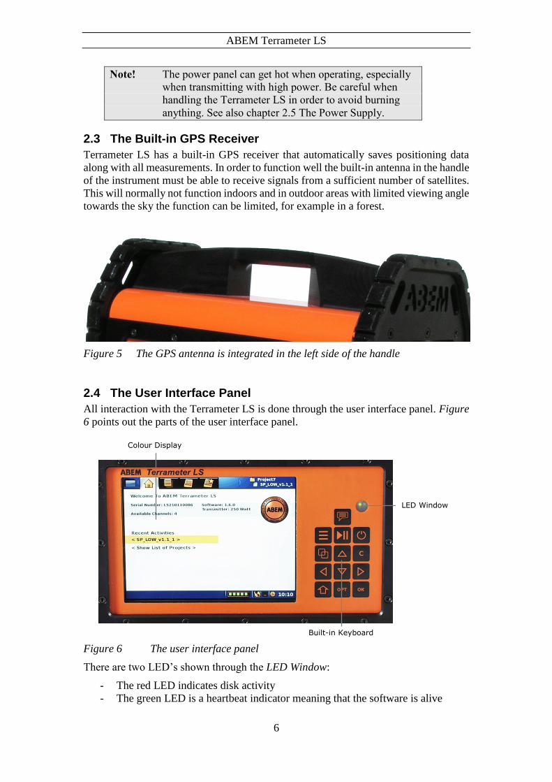
2.3 The Built-in GPS Receiver
Terrameter LS has a built-in GPS receiver that automatically saves positioning data
along with all measurements. In order to function well the built-in antenna in the handle
of the instrument must be able to receive signals from a sufficient number of satellites.
This will normally not function indoors and in outdoor areas with limited viewing angle
towards the sky the function can be limited, for example in a forest.
Figure 5 The GPS antenna is integrated in the left side of the handle
2.4 The User Interface Panel
All interaction with the Terrameter LS is done through the user interface panel. Figure
6 points out the parts of the user interface panel.
Figure 6 The user interface panel
There are two LED’s shown through the LED Window:
- The red LED indicates disk activity
- The green LED is a heartbeat indicator meaning that the software is alive
Colour Display
Built-in Keyboard
LED Window

ABEM Terrameter LS
7
2.5 The Power Supply
During stand-by the instrument drains very low levels of current. During transmission
though, the Terrameter LS will, depending on the circumstances use large currents,
sometimes up to 30A. The external battery and its cable must be designed accordingly.
Use the supplied cable set if possible. For field operations a good, adequate in capacity
and recently charged battery is vital for the best performance.
The internal battery is primarily designed as a backup power source for operating the
instrument during set up, data transfer etc. but it may also be used for limited low power
surveys. It has a quite snug fit in the battery compartment and there is no reason to
remove it when charging. If the protective liner that keeps the cells together is found
defective during inspection, please contact ABEM support for further information.
It is possible to fully run the Terrameter LS without the internal battery but for your
convenience you should always charge the battery before starting measurement
activities.
Once the instrument has been turned on and the external battery for any reason is
disconnected it will automatically switch to the internal battery. This function even
works during the initial start up process. This useful feature makes it possible to
disconnect the external battery temporarily without shutting the instrument off when
for instance moving from one measurement station to another.
The battery-switching device will, in any situation, give priority to the external battery
if its voltage is more than 9 V. There is no direct means to read out which one of the
batteries that is in use in a specific moment. However, provided that the internal battery
is charged, the battery indicator gives an indication. After hours of work the external
battery is going to be low in voltage. If, in that situation, the battery indicator shows a
fully charged battery the reason for that is that the internal battery now is giving power
to the instrument. More information about the internal and external voltage levels can
be found in chapter 4.6 The Power Source.
The table below shows a guideline to the battery indicator. The values are not very exact
but give an indication of the voltage level of the battery pack in use for the moment,
that is, the external or the internal battery. The battery indicator is the leftmost of the
Notification Icons on the Status Bar (Figure 7).
Indication Approximate voltage
Over 12.2 V
11.6 – 12.2 V
11.4 – 11.6 V
10.9 – 11.4 V
Under 10.9

ABEM Terrameter LS
8
If the external power source does not exist it switches to the internal battery.
However, the following start up scenario should be looked out for:
1. If the external battery has a voltage that is just over the OK limit the instrument
will proceed to the stage where the more power draining display lights up.
2. The voltage on the already weak battery will now drop below an acceptable level.
3. The instrument then goes into a resting state.
4. The external battery will now recover to a higher voltage level.
5. The instrument sees enough voltage to restart the start up sequence.
6. The display lights up with a following drop in voltage and a forced resting state.
This sequence can continue repeatedly for a long time. In case this happens the
immediate action is to disconnect the battery and have it replaced or charged. Always
use a good and newly charged battery for your survey.
After the transmitter has started the power supply voltage is allowed to temporarily drop
to 9V. The instrument may temporary indicate low battery voltage while transmitting
high current into the ground.
2.6 Operating in High Temperature Situations
Every individual Terrameter LS is operated for at least one hour in a heat chamber
during the delivery test. During normal operating condition a thermal fuse will turn off
the instrument if overheating occurs. This is to prevent damage and it will of course
halt the measuring process.
Some precautions to avoid overheating:
Protect the instrument from direct sunlight. Keep it in the shade, that is use a parasol
or similar if needed.
Do not operate the instrument in small closed spaces, like for example transport
boxes, where air cannot circulate freely. Especially the power panel must have good
ventilation.
2.7 Operating in a Thunderstorm
If a thunderstorm should come up while out in the field with the instrument then
remember to first stop a possibly ongoing measuring process and then disconnect the
cables from the terminals without touching any bare conductors. Never leave the cables
connected to the Terrameter LS overnight unless they are equipped with adequate
lightning protection since a thunderstorm may occur.
Never take measurements during a thunderstorm!

ABEM Terrameter LS
9
3 The User Interface
The user interacts with the instrument through the User Interface Panel. This chapter
explains the basics of this interaction.
3.1 The Display
The information shown on the display is called a Screen. Figure 7 shows the layout of
the Screen.
Active Project and Task Tabs Navigation Menu Item
View
Status Bar
Notification Icons Figure 7 The screen layout
The Screen layout parts:
- Navigation Menu Item and Tabs are described in chapter 3.3 Navigation
- View shows different information depending on where the user has navigated
- Active Project and Task shows the currently opened Project and Task
- Status Bar shows interactive messages in the left part and notifications in the
right part. Notification icons show Battery status, GPS status and time of day

ABEM Terrameter LS
10
3.2 The Keyboard
Commands from the user are entered through a keyboard. There is a built-in keyboard
but an external keyboard can also be used.
3.2.1 The Built-in Keyboard
The table lists the names of the buttons as referenced in this document.
<Memo>
<Left>
<Menu>
<Right>
<Play-Stop>
<Down>
<Power>
<Shift>
<Browse>
<Options>
<Up>
<Ok>
<Clear>
The corresponding function of the buttons are summarised below:
<Memo> (not implemented)
<Menu> Show the Navigation menu
<Play-Stop> Jump to the “Measure/Progress” View / Start or stop measuring
<Power> Turn instrument on or off
<Browse> Jump between the Tabs of a navigation Menu Item
<Up> Move Cursor / Highlight up
<Clear> Close dialog
<Left> Move Cursor / Highlight left
<Down> Move Cursor / Highlight down
<Right> Move Cursor / Highlight right
<Shift> Change function of other buttons
<Options> Show the option menu for the highlighted object
<Ok> Select / Show the keyboard emulator

ABEM Terrameter LS
11
3.2.2 The External Keyboard
A standard USB computer keyboard can be connected to the Terrameter LS and used
instead of the built-in keyboard. The mapping between the built-in buttons and the
computer keyboard is listed in this table:
<F9>
<Arrow Left>
<Alt>
<Arrow Down>
<F10>
<Arrow Right>
<F12>
<Shift>
<Tab>
<F11>
<Arrow Up>
<Enter>
<Esc>

ABEM Terrameter LS
12
3.3 Navigation
The viewable information of the instrument (called a View, see chapter 3.1) is divided
into a number of pages. These pages are arranged in a menu tree with two levels. The
top level has four Menu Items, each with a number of Sub Items.
The form “Menu Item/Sub Item” will be used in this document from now on when
referring to a specific View for instance “Instrument/Network” for the network
information View.
Figure 8 The Navigation Menu over the “Projects/Welcome” View
The details of the Navigation Menu are marked in Figure 9.
Figure 9 Navigation menu: Projects Menu Item: Welcome Sub Item marked

ABEM Terrameter LS
13
The four Menu Items are:
Projects (3.6 Data Concepts)
Settings (5.2.2 Data Acquisition Settings)
Measure (6.9 Performing Data Acquisition)
Instrument (4 The Instrument)
Each Sub Item corresponds to a specific Tab on the Screen (chapter 3.1 explains these
concepts). Each Tab represents a specific View of information. It’s a one-to-one match
between the three concepts:
- Sub Item is a part of the Navigation Menu and it matches a specific Tab/View
Screen
- Tab is a part of the Screen layout; it is a navigation help for the user
- View is a part of the Screen layout; it shows the requested information
There are three different ways to change the current View:
Stepping between Sub Items
― Press <Browse> to step forward
― Press <Shift> + <Browse> to step backwards
Make a direct change to the “Measure/Progress” View
― Press <Play-Stop>
Using the Navigation Menu
― Press <Menu> to bring up the Navigation Menu
― Press <Up> and/or <Down> to step up and down in the Navigation Menu
― Press <Right> to open a closed Menu Item and show its Sub Items
― Press <Ok> to show the View of the highlight
If a Menu Item instead of a Sub Item is highlighted then the change will be to the latest used View of that Menu Item
Note! The only way to change the View from one Menu Item to
any other Menu Item is via the Navigation Menu
3.3.1 The Start View
When starting the Terrameter LS the “Projects/Welcome” View (Figure 10) will appear.
Here the serial number of the instrument, the application software version, the number
of measuring channels, the transmitter firmware version, the network IP address and
the VPN tunnel address are displayed. Furthermore the name of the most recent
measurement activity is displayed at the top right part of the Screen.

ABEM Terrameter LS
14
Figure 10 The Start View
In the middle of the View there are two rows with shortcuts to other Views.
Using the shortcuts
― Press <Up> or <Down> to highlight one of the two rows
― Press <Ok> to change to the View
For the first of these rows there are two possible situations:
- If the active Project does not have any Task
then the text “< Task is missing. Please create >” will be shown.
Pressing <Ok> will in this case change View to the “Project/Task List” of the
active Project. This View is explained in chapter 3.6.2
- Otherwise if the active Project does have a Task
then the name of the active Task will be shown. See Figure 10 for an example.
Pressing <Ok> will in this case change to the “Measure/Progress” View of this
Task. This View is explained in chapter 6.9.1
For the second row the same thing will happen as a press on the <Browse> button, the
View will change to the “Project/Project List” View. Chapter 3.6.1 has an explanation
of this View.

ABEM Terrameter LS
15
3.4 The Option Menus
Figure 11Error! Reference source not found. shows an example of an option menu.
Option menus are available in four Views:
- “Projects/Project List”
- “Projects/Task List”
- “Projects/Task Templates”
- “Measure/Progress”
Figure 11 Option menu example
Opening and using an option menu
― Pressing <Options> will in most cases show a pop-up option menu
― Press <Up> or <Down> to highlight a menu item
Some menu items might be disabled and these cannot be highlighted
― Press <Ok> to perform the action of the highlighted menu item
The content of the option menu will differ depending on what type of line that is
highlighted when the <Options> button is pressed. It functions similar to a right-click
context menu on a desktop PC.
3.5 Changing Texts and Values
There are mainly three different ways to change values.
- Choosing from a fixed set of values (see 3.5.1)
- Editing texts (for instance names) using a keyboard emulator (see 3.5.2)
- Editing numerical values using a keypad emulator (see 3.5.2)
3.5.1 Fixed Set of Values
A left and right pointed arrowhead will surround the value when there is a fixed set of
values to choose from (Figure 12).

ABEM Terrameter LS
16
Figure 12 Example of a fixed choice value
Changing a fixed choice value
― Press <Left> and/or <Right>
3.5.2 The Keyboard Emulators
Two different keyboard emulators are used when the built-in keyboard is to be used to
enter text and data values. One emulator is alphanumeric and the other is numeric.
Alternatively an external keyboard can be used.
Figure 13 Alphanumerical keyboard emulator
Input Keys
Edit Text
Figure 14 Numerical keypad emulator with its parts pointed out
The edit text will be highlighted when a keyboard emulator is opened.
Opening a keyboard emulator

ABEM Terrameter LS
17
― Make sure the text to be edited is highlighted or has the blinking cursor inside
― Press <Ok>
If the edit text is numeric then the numerical keypad emulator (Figure 14) is shown otherwise the alphanumerical keyboard emulator is shown (Figure 13)
Navigating the emulators
― Press the arrow buttons (<Left> <Right> <Up> <Down>) to either move the
cursor within the edit text or to select an input key
Deleting from the edit text in the alphanumerical keyboard emulator
― Press <Left> and/or <Right> to move the cursor to the right of the character(s)
to be deleted
― Press <Down> to move the cursor from the edit text to the input keys
― Press <Right> until the “<-“ input key is selected
This input key works as a backspace button on a traditional PC keyboard
― Press <Ok> once for every character to be deleted
Resetting the edit text to “0” in the numerical keypad emulator
― Press <Down> to move the cursor from the edit text to the input keys
― Press <Right> until the “C“ input key is selected
― Press <Ok> and the number is replaced with a “0”
Changing the edit text
― Press <Left> and/or <Right> to move the cursor to the correct place within the
edit text
― Press <Down> to move the cursor from the edit text to the input keys
― Navigate to the wanted input key
― Press <Ok>
Substituting the edit text when the edit text is highlighted
― Press <Down> to move the cursor from the edit text to the input keys
― Navigate to the wanted input key
― Press <Ok> and the number or character will replace the edit text
Saving the text
― Navigate to the input key at the bottom right (“Done!” or “OK”)
― Press <Ok>

ABEM Terrameter LS
18
Canceling without saving
Note! This is only possible when the keyboard emulator has
been opened from a dialog where there is a Cancel
button. An example of this is the Project Name dialog
(Figure 19)
― Navigate to the input key at the bottom right (“Done!” or “OK”)
― Press <Ok>
― Highlight the “Cancel” button and press <Ok>
3.6 Data Concepts
Certain concepts are used to handle and present measurement data in a comprehensible
way. They are Project, Task and Template. This chapter will explain these concepts as
well as explain how to use them on the actual instrument.
3.6.1 Project
A Project is a container for measurement Tasks. Typically the Tasks of a Project are
from the same site.
Projects are managed in the “Projects/Project List” View (Figure 15). Here Projects
can be created, deleted, renamed or exported.
Figure 15 Project List View
Create a new Project

ABEM Terrameter LS
19
― Move the highlight to the topmost row (“<Create New Project>”)
― Press <Ok>
Alternatively the “<Create New Project>” item of the Project option menu can be
used to create a new Project, see below
Opening the Project option menu
― Move the highlight to the wanted Project
― Press <Options> and the option menu of Figure 16 will be shown
Figure 16 Project Option menu with Open item highlighted
The Menu Items of the Project option menu:
- Open: The Project is made active and the “Projects/Task List” for the Project
is shown
- Delete: A confirmation dialog is shown and the Project will be deleted if the
user confirms the deletion (Figure 17)
- Export: see chapter 7.2.5 Export a Project
- Rename: see below
- Create New Project: Creates a new Project
Figure 17 Confirm Project Delete dialog
ABEM Terrameter LS
20
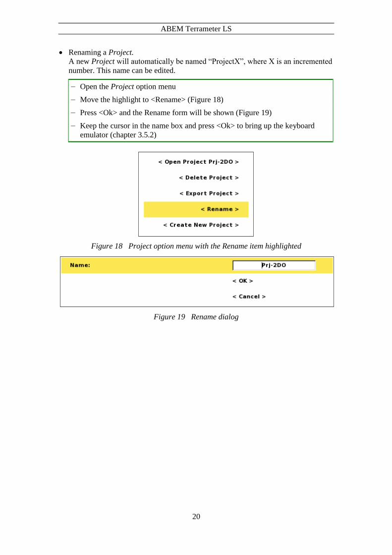
Renaming a Project.
A new Project will automatically be named “ProjectX”, where X is an incremented
number. This name can be edited.
― Open the Project option menu
― Move the highlight to <Rename> (Figure 18)
― Press <Ok> and the Rename form will be shown (Figure 19)
― Keep the cursor in the name box and press <Ok> to bring up the keyboard
emulator (chapter 3.5.2)
Figure 18 Project option menu with the Rename item highlighted
Figure 19 Rename dialog

ABEM Terrameter LS
21
3.6.2 Task
A Task is a set of measurements as defined by a measurement protocol. A Task can,
for instance, be a 2D resistivity imaging line, including one or many roll-along steps.
Tasks are managed in the “Projects/ Task List” View (Figure 20). Here Tasks can be
created, deleted and renamed, among other things.
Figure 20 Task list View
Create a new Task
When creating a new Task the type of electrode spread must be defined, for
instance the 2D layout with 4x21 cables or the 2D layout with 4x16 cables.
Furthermore a protocol file is selected and electrode take-out spacings are given.
― Move the highlight to the topmost row (“<Create New Task>”)
― Press <Ok> and the Create New Task dialog will be shown (Figure 21)
― Press <Left> and/or <Right> to pick the electrode spread
― Press <Down> to highlight Protocol
― Press <Left> and/or <Right> to pick the protocol file
― If the default values of electrode spacing need to be changed then:
― Press <Down> to highlight Electrode Spacing X and/or Y
― Press <Ok> and the numerical keyboard emulator will be shown
― Enter the wanted electrode spacing and return, see chapter 3.5.2
― Press <Down> to highlight the OK button

ABEM Terrameter LS
22
― Press <Ok>
Figure 21 Create new task dialog
Alternatively the “<Create New Task>” item of the Task option menu can be used
to create a new Task, see below.
Note! After creating a new Task it may be necessary to check,
and possibly modify, the data acquisition settings before
starting taking measurements. For this reason the
“Settings/Receiver” View will automatically be shown
for a newly created Task, see chapter 5.2.2 Data
Acquisition Settings
Opening the Task option menu
― Move the highlight to the wanted Task
― Press <Options> and the option menu of Figure 22 will be shown
ABEM Terrameter LS
23
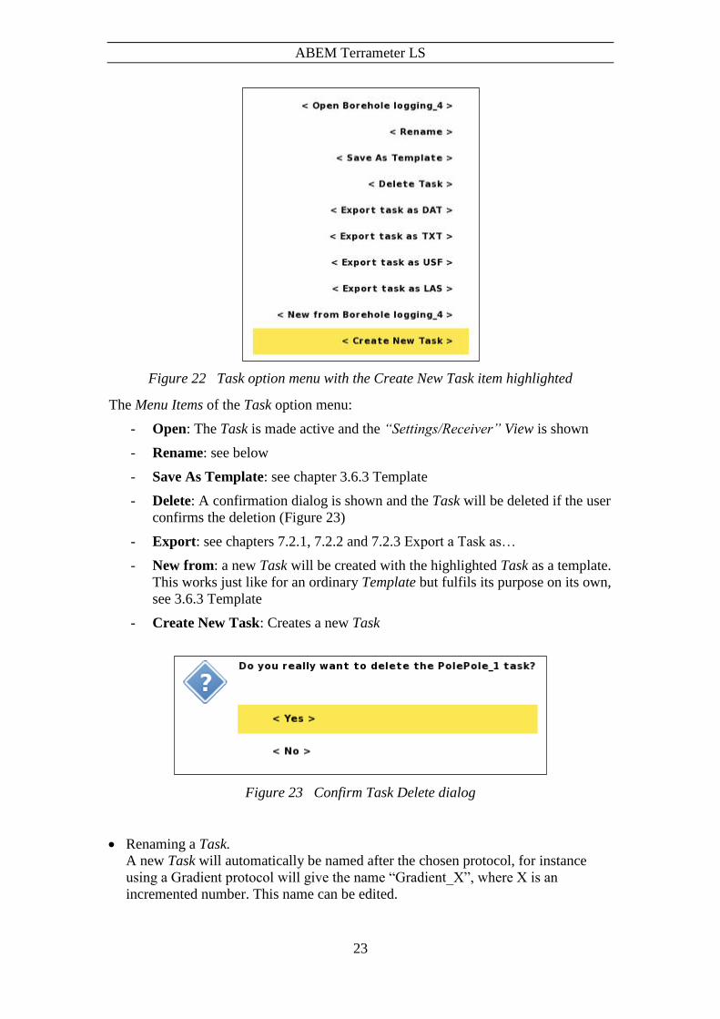
Figure 22 Task option menu with the Create New Task item highlighted
The Menu Items of the Task option menu:
- Open: The Task is made active and the “Settings/Receiver” View is shown
- Rename: see below
- Save As Template: see chapter 3.6.3 Template
- Delete: A confirmation dialog is shown and the Task will be deleted if the user
confirms the deletion (Figure 23)
- Export: see chapters 7.2.1, 7.2.2 and 7.2.3 Export a Task as…
- New from: a new Task will be created with the highlighted Task as a template.
This works just like for an ordinary Template but fulfils its purpose on its own,
see 3.6.3 Template
- Create New Task: Creates a new Task
Figure 23 Confirm Task Delete dialog
Renaming a Task.
A new Task will automatically be named after the chosen protocol, for instance
using a Gradient protocol will give the name “Gradient_X”, where X is an
incremented number. This name can be edited.

ABEM Terrameter LS
24
― Open the Task option menu
― Move the highlight to <Rename> (Figure 24)
― Press <Ok> and the Rename form will be shown. This is similar to the rename
form of the Project (Figure 19)
― Keep the cursor in the name box and press <Ok> to bring up the keyboard
emulator (chapter 3.5.2)
Figure 24 Task Option menu with the Rename item highlighted
3.6.3 Template
A complete measuring setup from a Task can be saved as a Template. This makes it
easy to create a new Task with exactly the same data acquisition settings as used
previously, avoiding the risk to overlook changing any setting.
Note! There is no acquisition data stored in a Template, just
Task settings.
ABEM Terrameter LS
25
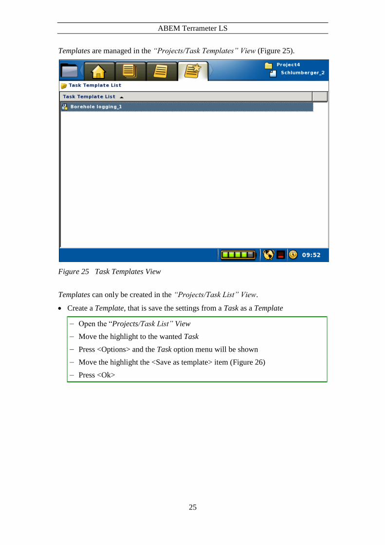
Templates are managed in the “Projects/Task Templates” View (Figure 25).
Figure 25 Task Templates View
Templates can only be created in the “Projects/Task List” View.
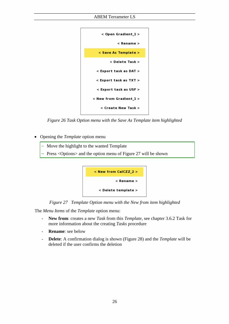
Create a Template, that is save the settings from a Task as a Template
― Open the “Projects/Task List” View
― Move the highlight to the wanted Task
― Press <Options> and the Task option menu will be shown
― Move the highlight the <Save as template> item (Figure 26)
― Press <Ok>
ABEM Terrameter LS
26
Figure 26 Task Option menu with the Save As Template item highlighted
Opening the Template option menu
― Move the highlight to the wanted Template
― Press <Options> and the option menu of Figure 27 will be shown
Figure 27 Template Option menu with the New from item highlighted
The Menu Items of the Template option menu:
- New from: creates a new Task from this Template, see chapter 3.6.2 Task for
more information about the creating Tasks procedure
- Rename: see below
- Delete: A confirmation dialog is shown (Figure 28) and the Template will be
deleted if the user confirms the deletion

ABEM Terrameter LS
27
Figure 28 Confirm Template Delete dialog
Renaming a Template.
A new Template will automatically be named after the Task it was created from.
This name can be edited.
― Open the Template option menu
― Move the highlight to <Rename>
― Press <Ok> and the Rename form will be shown.
This is similar to the rename form of the Project (Figure 19)
― Keep the cursor in the name box and press <Ok> to bring up the keyboard
emulator (chapter 3.5.2)

ABEM Terrameter LS
28
4 The Instrument
Settings and information that is specific to the instrument are handled in the Instrument
Menu Item of the Navigation Menu (Figure 29). Each Sub Item is explained below.
Figure 29 Navigation menu: Instrument Menu Item: Storage Sub Item marked

ABEM Terrameter LS
29
4.1 The Data Storage
The Instrument/Storage View (Figure 30) shows information about the data storage.
Figure 30 Information view for data storage
4.2 The Network
While working with the instrument in the office it will normally be connected to a
network with a DHCP-server. The IP number given to the instrument will be displayed
on the Start view and on the “Instrument/Network” View (Figure 31 Network
status viewError! Reference source not found.). Two IP numbers may be displayed.
The first is assigned for use in the local network. The local network address is labelled
“eth0:” and is needed for establishing communication to the instrument via a network
connection using the Terrameter LS Toolbox. The second is only displayed if a
connection can be established with ABEM’s remote technical support site via VPN,
Virtual Private Network (see section 8.4 Remote Diagnostics).

ABEM Terrameter LS
30
Figure 31 Network status view
In the field it might be useful to connect a computer directly to the instrument. For this
to work the DHCP server in the Terrameter LS must be activated from the
“Instrument/Network” View. For this to succeed the sequence is critical and the
following procedure is to be followed:
1) Make sure that no network cable is connected
2) In the “Instrument/Network” View set DHCP to On
3) Go to the GPS View by pressing <Browse>
4) Wait for a few seconds
5) Go back to Network View by pressing <Shift> + <Browse>
6) Check that the eth0 address is 192.168.23.1
7) Connect the PC and the LS with the network cable
8) Wait until the PC has received an IP address
9) Perform your operations on hand using the Utility program
10) Unplug the PC
11) On the LS set DHCP server to Off
12) Turn off LS
Warning! Before connecting to an office network be absolute
certain that the DHCP server is set to OFF on the
Terrameter LS. If an instrument with the DHCP server
activated is connected to a network with another DHCP
server active it can create chaos in the network and
seriously affect other users in the network.
ABEM Terrameter LS
31
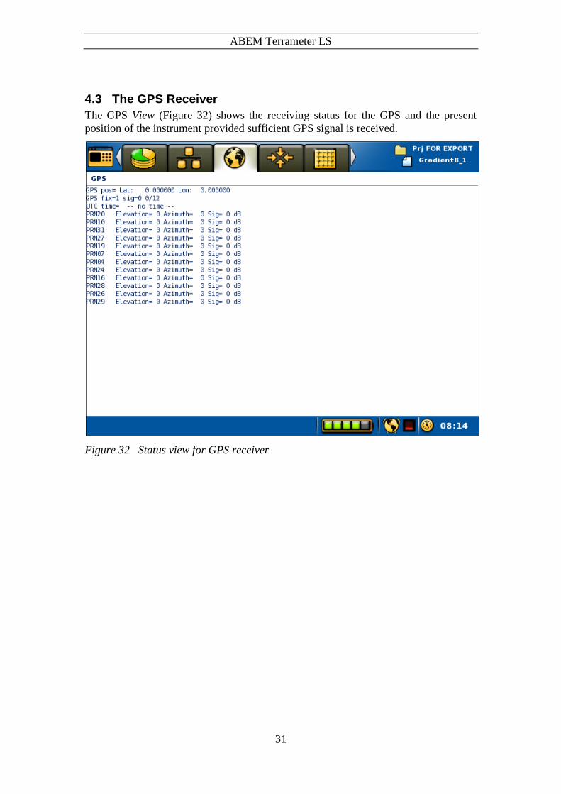
4.3 The GPS Receiver
The GPS View (Figure 32) shows the receiving status for the GPS and the present
position of the instrument provided sufficient GPS signal is received.
Figure 32 Status view for GPS receiver

ABEM Terrameter LS
32
4.4 Calibration
Calibration of the instrument is done at the factory before delivery. Users has no need
to access this page. An unlock key must be typed in to access the View (Figure 33), and
a complete calibration requires special equipment.
Figure 33 Calibration view
4.5 The Relay Switch
The relay switch consists of four relay cards that can handle 16 electrodes each. The
VES version of the instrument has one relay card. The relay switch can be re-
configured by an optimisation routine in the instrument software depending on how
many measuring channels the instrument is equipped with. This design allows
measurement with many receiver channels without having a prohibitively large relay
switch2. The design chosen here provides a good compromise between capability vs.
physical size and cost, and is suitable for multi-channel measurements.
For a 4-channel instrument it is possible for each measuring channel to measure on an
arbitrary electrode pair between 1 and 64 with no restriction. For an instrument with 8
or 12 measuring channels the measuring channels will be distributed in the relay switch
by an optimisation algorithm, and the efficiency of use of the channels will depend on
2 For example; a regular matrix switch with full freedom in switching for 12 measuring channels and 64
electrodes would require 1664 relays, which would be bulky and expensive.

ABEM Terrameter LS
33
which potential electrode pairs are to be measured for a current transmission electrode
pair. The instrument software optimises the use of measuring channels so that as many
measurements as possible are taken simultaneously for each measuring cycle, given the
capability and limitations of the relay switch. The maximum efficiency is achieved if
the electrodes of the receiver channels are distributed between the relay cards rather
than all being concentrated to one relay card.
Input for the measuring channel optimisation is what is written within a <Measure>
section in the XML format measuring sequence (protocol) file (see Appendix C. Spread
and Measuring Sequence Files, for details). If all receiver pairs can be measured within
one current transmission that will be done, but if necessary measuring will be divided
on two or more rounds. Hence, it is allowed to list more receiver combinations than
there are measuring channels in the instrument within one <Measure> section.
The measurement efficiency will of course be dependent on for example how many
measurements there are per current electrode pair, and with a multi-channel instrument
multiples of 4 measurements are optimal (4, 8, 12 etc).
The present status of the relay switch can be viewed in a table in the relay switch status
Tab (Figure 34.).
Figure 34 Relay switch status view
4.5.1 The External Relay Switch(es)
If more than 64 electrodes switching capability is required one or more external relay
switching units (electrode selectors) of type ES10-64C can be connected. In case more

ABEM Terrameter LS
34
than one expansion unit is needed they must be of type ES10-64C (orange colour), the
older ES10-64 (grey colour) cannot link to other units.
Figure 35 ES10-64C connected to a Terrameter LS
The ES10-64C should be connected at the AUX connector via a multifunction cable
(ABEM part no 33 0020 11) (Figure 35). The distance between the Terrameter LS and
the first ES10-64C is limited by the length of the multifunction cable (33 0020 11). In
case it is not long enough, an ”ES10-64C Communication Adapter” (33 0022 81) plus
an “ES10-64C Interlink Cable” is required.
Note! Some ES10-64C units have a start-up problem. They
consume more power (12V DC) than expected during
start. This can be solved by using external power, or by
doing a minor hardware modification of the ES10-64C
controller board. Please contact ABEM in case you
experience this problem.
Instrument software version 1.5.1 or higher is required to use an external relay switch.
The software will attempt to connect with the ES10-64C at measuring start, provided
the selected spread and protocol file demands an external relay switch. The spread files
must hold information about the external switching unit, as described in “Appendix C.
Spread and Measuring Sequence Files”.
4.6 The Power Source
The power supply View (Figure 36) shows the status for the power supply and internal
temperature of the instrument. The actual values are shown and they are complemented
with minimum and maximum values within square brackets.

ABEM Terrameter LS
35
Figure 36 Status view for power supply and temperature

ABEM Terrameter LS
36
5 Measurement Preparation
5.1 Save Field Time by Doing the Right Preparations
Look through archive material for the area (topographical maps, geological maps, aerial
photographs, reports etc.), and consider whether resistivity surveying is a suitable
method for the current problem. If so, select possible profile lines.
Walk around the area to be surveyed with maps and/or aerial photographs at hand (aerial
photographs and a pocket stereoscope is often highly useful) to select the optimal
profile lines. Walk along the entire length of the planned profiles before putting out any
equipment, to ensure that the selected lines are practical.
Poor electrode contact is the most common reason for bad data. Bring suitable hammers
for installing the electrodes in the field, for instance polyurethane (PUR) covered
hammers that give good force without damaging the electrodes. It is also often
necessary to water the ground around the electrodes, sometimes with addition of salt
and sometimes a substance to make the water stay in place during measurements (for
instance drilling polymer or bentonite). In cases with paved surfaces it may be necessary
to drill holes for inserting the electrodes.
Electrical installations and grounded metal objects may disturb the measurements and
create noise, be observant and take notes of possible sources of disturbance.
5.2 Preparing Data Acquisition
5.2.1 Create Projects and Tasks
In order to prepare for data acquisition at least one Project with one or more Tasks must
exist. Chapters 3.6.1 Project and 3.6.2 Task explains how to create Projects and Tasks.
Alternatively measurements can be added to existing Projects and Tasks.
All data from a Project is saved in a single database file. It is recommended not to make
the Project too large as it may become cumbersome and slow to handle. In large data
acquisition campaigns it may be suitable to make a new Project for every day in the
field.
Also see chapter 6.11 Full Waveform Data for more information about large amounts
of data.
5.2.2 Data Acquisition Settings
Data acquisition settings are controlled within the “Settings” Menu Item, under which
there are four Views: “Receiver Settings”, “Transmitter Settings”, “IP Window
Settings” and “Borehole Log Settings”.
ABEM Terrameter LS
37
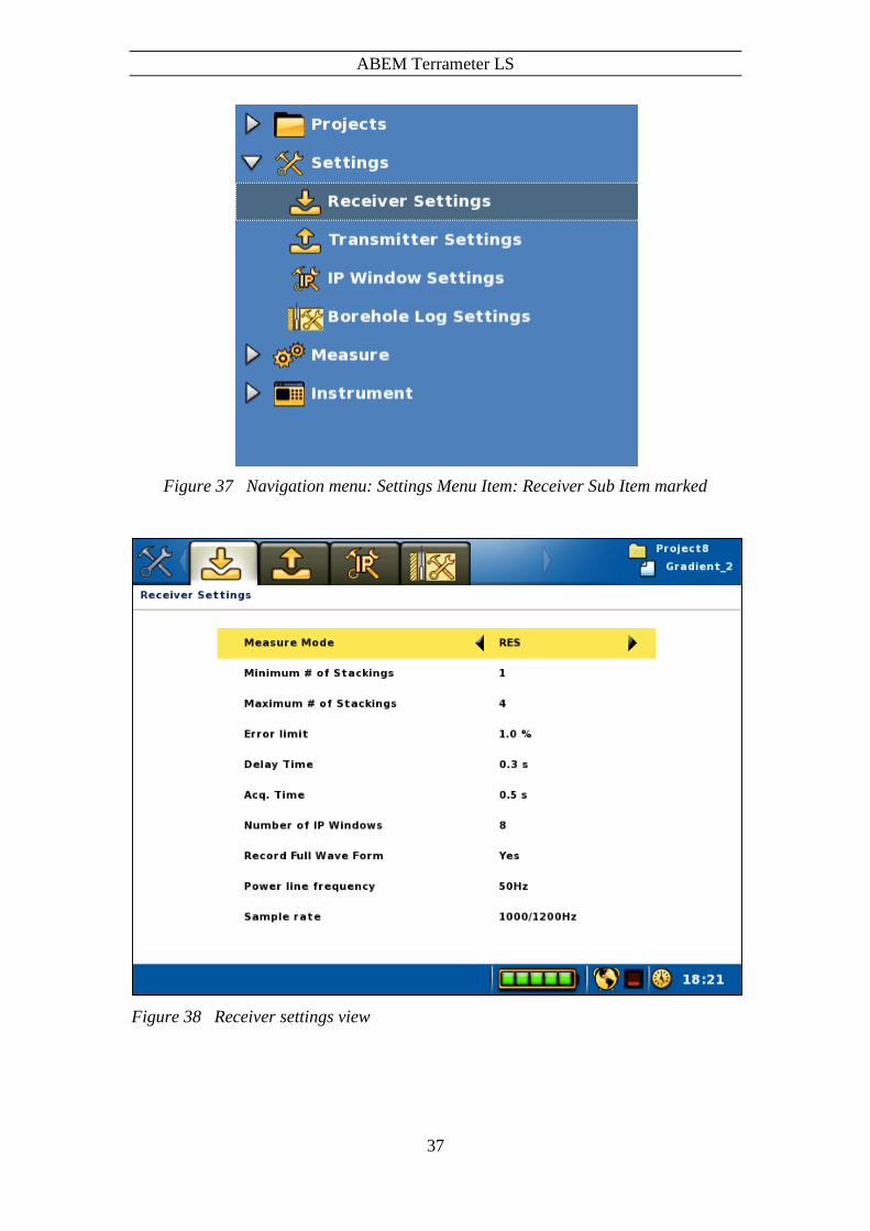
Figure 37 Navigation menu: Settings Menu Item: Receiver Sub Item marked
Figure 38 Receiver settings view

ABEM Terrameter LS
38
The available settings on the Receiver Settings View (Figure 38):
Measure mode Measuring mode options include Self Potential (SP),
Resistivity (RES), and a combination of Resistivity and
Induced Polarization (RES, IP)
Minimum # of
Stackings
Maximum # of
Stackings
The number of stackings needed depend on site condition,
electrode spread size and the type of electrode array used. It is
recommended to start out a task with multiple stackings, and if
the standard deviation is very favourable the maximum number
of stackings value may be reduced even as low as to one to
speed up measurements
Error limit The error limit is equivalent to the standard deviation between
repeated measurements (stackings) divided by the mean value
for a data point, also known as variation coefficient. Measuring
will be repeated the minimum number of stackings requested.
Measurement for the current data point will stop if the variation
falls within the specified limit. If not it will continue until
either the variation drops to the limit or the maximum number
of stackings have been reached
Delay Time The delay time setting defines the interval from switching on
current transmission until signal integration for the resistivity
measurement starts. Ideally the delay time should be long
enough for the ground to become fully charged. If set to short
charge-up effect of the ground may cause decreased data
quality
Acq. Time The acquisition time defines for how long signal integration
lasts for each part of the measuring cycle (see Appendix B.
Measurement Modes). Generally the principle is that the longer
the acquisition time, the better the data quality.
It should be noted, that in some countries the railway system
uses a frequency of 16 2/3 Hz, which means that multiples of 60
ms are required (note that such noise may be observed many
kilometres or even tens of kilometres away from railway lines)
Number of IP
Windows
The number of IP windows only applies to measurements in IP
mode, and the timings are defined in the “Measure/IP Windows
Settings” View (Figure 40)
Record Full Wave
Form
If “Record full waveform” is checked all measured full
waveform data will be saved to disk with a time resolution
based on the “Sample rate” setting. See chapter 6.11 Full
Waveform Data for more information on this issue (page 68)
Power line
frequency
The power line frequency should be set to 50 Hz or 60 Hz
depending on the system used in the area of investigation, and
is used to adjust measure parameters for filtering of power line
noise
Sample rate The sample rate specifies at which measurements are sampled.
A higher sample rate means that more samples will be used for
data calculations, and can be especially useful for IP data

ABEM Terrameter LS
39
Figure 39 Transmitter settings view
The available settings on the Transmitter Settings View (Figure 39):
Minimum
Current
Sets the minimum current that can be used for measurements. It is
recommended to leave the minimum current at the lowest setting,
as raising this value will limit the ability to perform measurements
in high ground resistance
Maximum
Current Sets the maximum current that can be used for measurements. It
should be selected according to site conditions (electrode
grounding conditions, noise levels etc), electrode spread size and
type of electrode array, to achieve good signal-to-noise ratio and
productivity. Setting the maximum current to a lower than
maximum value can be used for saving battery power
Max Power Maximum output power can be limited, for example to save
battery power
Max output
voltage
Maximum output voltage from the transmitter can be limited, if
for example the electrode cables used are not designed for the
maximum voltage
Electrode Test Electrode test is carried out using the “Focus One” method, in
which the resistance of each electrode is measured against all the
other electrodes. The alternative “No” is not recommended for

ABEM Terrameter LS
40
normal data acquisition as it may lead to acquisition of a lot of
junk data from electrode with inadequate ground contact.
Bad electrode
Fail electrode
Thresholds for acceptable electrode contact resistance. Needs to
be set according to site conditions, as ground resistance can vary a
lot
Electrode test
current
The maximum current used for the electrode test. 20mA is
normally a good value to use
Load variation
margin (10%)
Load variation margin defines how big changes in load resistance
is allowed during current transmission. If the change is bigger
than the set value, the measurement will stop and an error message
shown (typically “Not regulating”). Default value is 10 %.
Increasing this value can improve measurements in difficult
conditions, but will also limit the maximum power output
Figure 40 IP Window settings view
The timing setup for the off-time measurements in IP-mode is defined in the "IP
Window Settings" View (Figure 40). The current-off time will be equivalent to "IP
Minimum Off Time" except if the total sum of IP delay times and the sum of integration
time for IP windows are larger. It is recommended to set each IP time window to a
multiple of the local power line net frequency period time (for instance 20, 40, 60, or
100 ms in case of 50 Hz frequency).
ABEM Terrameter LS
41
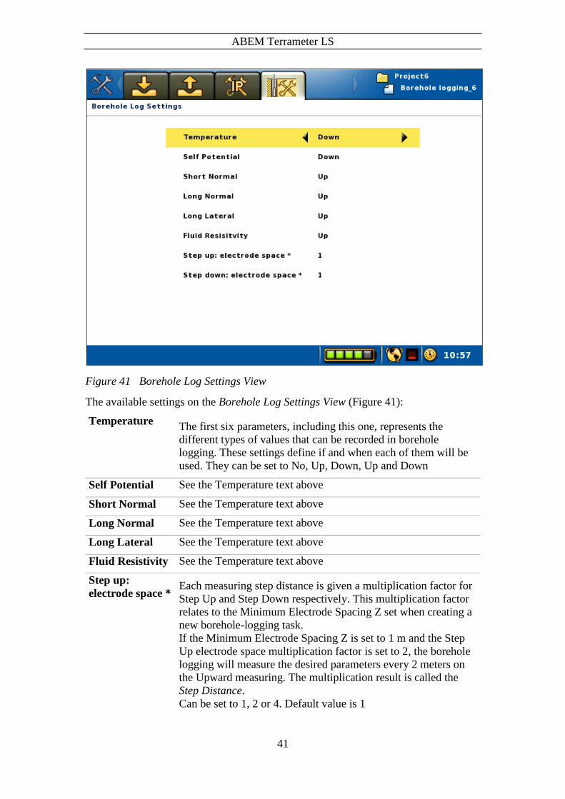
Figure 41 Borehole Log Settings View
The available settings on the Borehole Log Settings View (Figure 41):
Temperature The first six parameters, including this one, represents the
different types of values that can be recorded in borehole
logging. These settings define if and when each of them will be
used. They can be set to No, Up, Down, Up and Down
Self Potential See the Temperature text above
Short Normal See the Temperature text above
Long Normal See the Temperature text above
Long Lateral See the Temperature text above
Fluid Resistivity See the Temperature text above
Step up:
electrode space * Each measuring step distance is given a multiplication factor for
Step Up and Step Down respectively. This multiplication factor
relates to the Minimum Electrode Spacing Z set when creating a
new borehole-logging task.
If the Minimum Electrode Spacing Z is set to 1 m and the Step
Up electrode space multiplication factor is set to 2, the borehole
logging will measure the desired parameters every 2 meters on
the Upward measuring. The multiplication result is called the
Step Distance.
Can be set to 1, 2 or 4. Default value is 1
ABEM Terrameter LS
42
Step down:
electrode space *
See the Step up text above
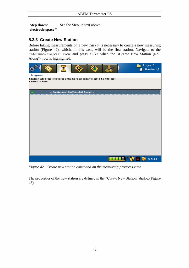
5.2.3 Create New Station
Before taking measurements on a new Task it is necessary to create a new measuring
station (Figure 42), which, in this case, will be the first station. Navigate to the
“Measure/Progress” View and press <Ok> when the <Create New Station (Roll
Along)> row is highlighted.
Figure 42 Create new station command on the measuring progress view
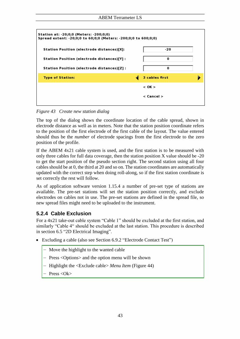
The properties of the new station are defined in the “Create New Station” dialog (Figure
43).
ABEM Terrameter LS
43
Figure 43 Create new station dialog
The top of the dialog shows the coordinate location of the cable spread, shown in
electrode distance as well as in meters. Note that the station position coordinate refers
to the position of the first electrode of the first cable of the layout. The value entered
should thus be the number of electrode spacings from the first electrode to the zero
position of the profile.
If the ABEM 4x21 cable system is used, and the first station is to be measured with
only three cables for full data coverage, then the station position X value should be -20
to get the start position of the pseudo section right. The second station using all four
cables should be at 0, the third at 20 and so on. The station coordinates are automatically
updated with the correct step when doing roll-along, so if the first station coordinate is
set correctly the rest will follow.
As of application software version 1.15.4 a number of pre-set type of stations are
available. The pre-set stations will set the station position correctly, and exclude
electrodes on cables not in use. The pre-set stations are defined in the spread file, so
new spread files might need to be uploaded to the instrument.
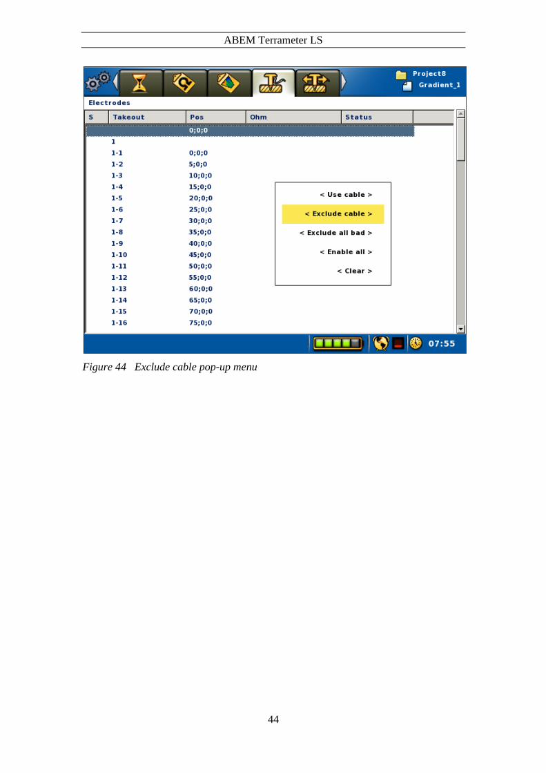
5.2.4 Cable Exclusion
For a 4x21 take-out cable system “Cable 1” should be excluded at the first station, and
similarly “Cable 4“ should be excluded at the last station. This procedure is described
in section 6.5 “2D Electrical Imaging”.
Excluding a cable (also see Section 6.9.2 “Electrode Contact Test”)
― Move the highlight to the wanted cable
― Press <Options> and the option menu will be shown
― Highlight the <Exclude cable> Menu Item (Figure 44)
― Press <Ok>
ABEM Terrameter LS
44
Figure 44 Exclude cable pop-up menu

ABEM Terrameter LS
45
6 Measurement Procedures
6.1 General
For general information on geoelectrical imaging please consult a modern geophysical
textbook or tutorial.
Note! Moisture and/or dirt in the connectors will compromise
the data quality and may even cause permanent damage
to the connectors. Always keep the protection caps
clean and in place whenever possible. Let the
protection caps protect each other when the cables
are connected as shown in Figure 45.
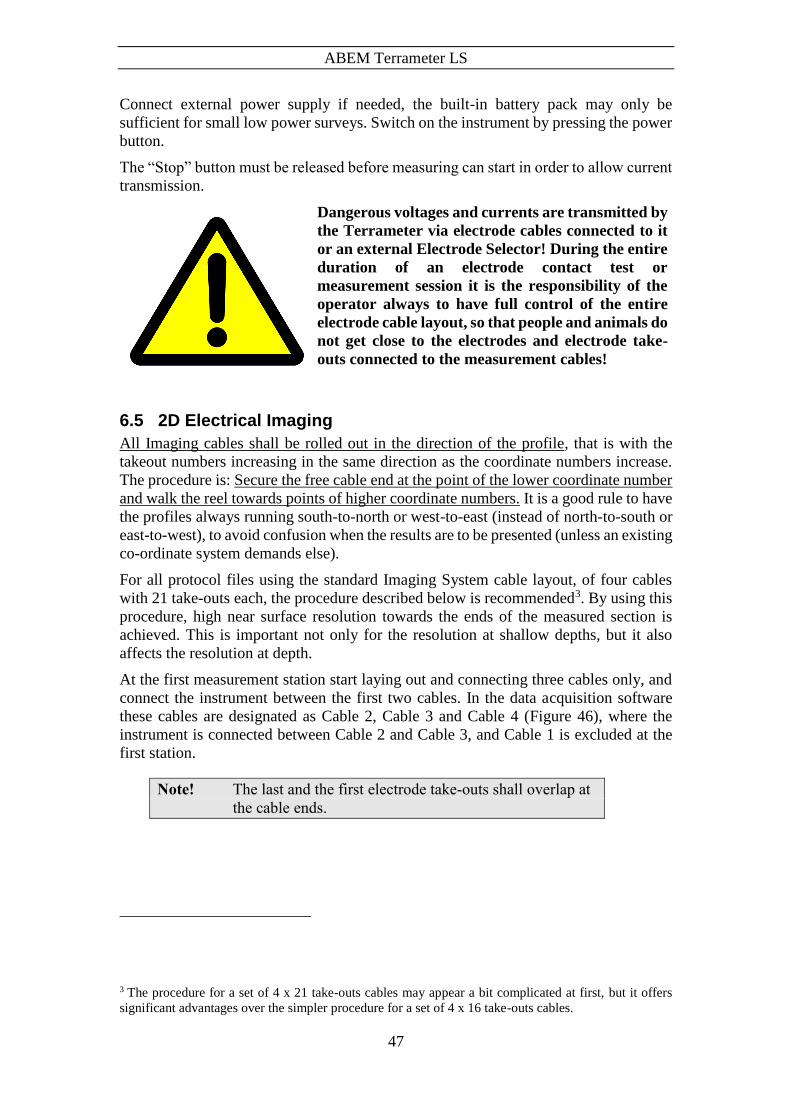
Dangerous voltages and currents are transmitted by
the Terrameter via electrode cables connected to it
or an external Electrode Selector! During the entire
duration of an electrode contact test or
measurement session it is the responsibility of the
operator always to have full control of the entire
electrode cable layout, so that people and animals do
not get close to the electrodes and electrode take-
outs connected to the measurement cables!
6.2 Essential Equipment
The following equipment is mandatory for data acquisition using the ABEM Terrameter
LS System.
To ensure proper function during geoelectrical imaging with medium to high power
the Terrameter should be powered from an external battery, for instance a gelled
lead-acid battery or a car battery (25 – 70 Ah)
Figure 45 Connecting the dust caps

ABEM Terrameter LS
46
Multi-electrode Imaging spread cables and suitable quantity of cable joints and
cable jumpers
Suitable quantity of electrodes
Double check that the internal and external batteries for the Terrameter are charged
before going to the field!
6.3 Recommended Additional Equipment
Often additional equipment is required for efficient acquisition of good quality data.
The following list is an attempt to summarize frequently needed additional equipment.
Spare external battery
Battery charger(s) if operation away from the home base for more than one day
A set of walkie-talkies, if cables with long electrode take-out spacing is used (that
is more than 2 meters between each take-out).
Polyurethane hammers of Stanley type (two or more) for hammering down
electrodes.
Plastic bottles for water with added salt and viscosity increasing polymer, to
improve electrode contact in dry ground. A drill mud polymer (such as Johnson
Revert or similar) added to the water can increase the viscosity to prevent draining
away during measurement in permeable soils. Mix salt and polymer with water to
suitable viscosity, it may be wise to do this in buckets before pouring the mixture
into plastic bottles of convenient size.
At least an additional double amount of electrodes and jumpers if operating in areas
with dry ground giving contact difficulties
Spray paint and pegs to mark out profile lines
Non-metallic ruling tape to measure distance from profile line to reference objects,
or to measure electrode spacing if smaller spacing than the take-out spacing are to
be used
Levelling equipment and / or differential GPS receiver if topography needs to be
recorded (depends on type of terrain)
Remote electrode cable(s) if pole-pole or pole-dipole array is used
Pocket multimeter with continuity check function for error detection
6.4 Setting up the Hardware
Roll out the electrode cables and connect the electrodes to the electrode cable. Be
careful to ensure that adequate electrode contact is provided, and the cable jumpers that
connect the electrodes to the electrode cables are in good condition and properly
connected. It is recommended to twist or slide the connector up and down while
connecting, to remove dirt or oxide on the contact surfaces.
Connect the electrode cables to Terrameter LS, making sure to connect them in the right
order in relation to the cable layout used. Please see chapter 6 Measurement Procedures
for a more detailed description for different types of surveying / imaging.
ABEM Terrameter LS
47
Connect external power supply if needed, the built-in battery pack may only be
sufficient for small low power surveys. Switch on the instrument by pressing the power
button.
The “Stop” button must be released before measuring can start in order to allow current
transmission.
Dangerous voltages and currents are transmitted by
the Terrameter via electrode cables connected to it
or an external Electrode Selector! During the entire
duration of an electrode contact test or
measurement session it is the responsibility of the
operator always to have full control of the entire
electrode cable layout, so that people and animals do
not get close to the electrodes and electrode take-
outs connected to the measurement cables!
6.5 2D Electrical Imaging
All Imaging cables shall be rolled out in the direction of the profile, that is with the
takeout numbers increasing in the same direction as the coordinate numbers increase.
The procedure is: Secure the free cable end at the point of the lower coordinate number
and walk the reel towards points of higher coordinate numbers. It is a good rule to have
the profiles always running south-to-north or west-to-east (instead of north-to-south or
east-to-west), to avoid confusion when the results are to be presented (unless an existing
co-ordinate system demands else).
For all protocol files using the standard Imaging System cable layout, of four cables
with 21 take-outs each, the procedure described below is recommended3. By using this
procedure, high near surface resolution towards the ends of the measured section is
achieved. This is important not only for the resolution at shallow depths, but it also
affects the resolution at depth.
At the first measurement station start laying out and connecting three cables only, and
connect the instrument between the first two cables. In the data acquisition software
these cables are designated as Cable 2, Cable 3 and Cable 4 (Figure 46), where the
instrument is connected between Cable 2 and Cable 3, and Cable 1 is excluded at the
first station.
Note! The last and the first electrode take-outs shall overlap at
the cable ends.
3 The procedure for a set of 4 x 21 take-outs cables may appear a bit complicated at first, but it offers
significant advantages over the simpler procedure for a set of 4 x 16 take-outs cables.
ABEM Terrameter LS
48
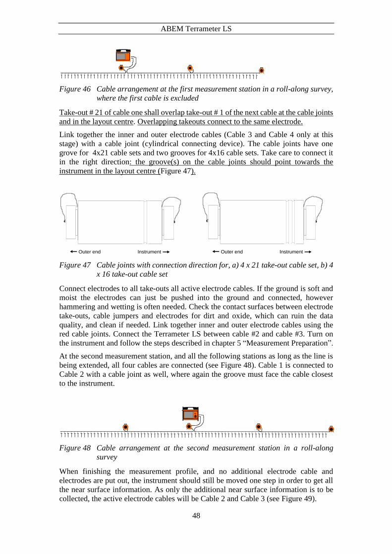
Figure 46 Cable arrangement at the first measurement station in a roll-along survey,
where the first cable is excluded
Take-out # 21 of cable one shall overlap take-out # 1 of the next cable at the cable joints
and in the layout centre. Overlapping takeouts connect to the same electrode.
Link together the inner and outer electrode cables (Cable 3 and Cable 4 only at this
stage) with a cable joint (cylindrical connecting device). The cable joints have one
grove for 4x21 cable sets and two grooves for 4x16 cable sets. Take care to connect it
in the right direction: the groove(s) on the cable joints should point towards the
instrument in the layout centre (Figure 47).
Figure 47 Cable joints with connection direction for, a) 4 x 21 take-out cable set, b) 4
x 16 take-out cable set
Connect electrodes to all take-outs all active electrode cables. If the ground is soft and
moist the electrodes can just be pushed into the ground and connected, however
hammering and wetting is often needed. Check the contact surfaces between electrode
take-outs, cable jumpers and electrodes for dirt and oxide, which can ruin the data
quality, and clean if needed. Link together inner and outer electrode cables using the
red cable joints. Connect the Terrameter LS between cable #2 and cable #3. Turn on
the instrument and follow the steps described in chapter 5 “Measurement Preparation”.
At the second measurement station, and all the following stations as long as the line is
being extended, all four cables are connected (see Figure 48). Cable 1 is connected to
Cable 2 with a cable joint as well, where again the groove must face the cable closest
to the instrument.
Figure 48 Cable arrangement at the second measurement station in a roll-along
survey
When finishing the measurement profile, and no additional electrode cable and
electrodes are put out, the instrument should still be moved one step in order to get all
the near surface information. As only the additional near surface information is to be
collected, the active electrode cables will be Cable 2 and Cable 3 (see Figure 49).
InstrumentOuter end InstrumentOuter end

ABEM Terrameter LS
49
Figure 49 Cable arrangement at the last measurement station
For a cable set of 4 cables with 16 electrode take-outs each it is simpler since all possible
measurements can be taken with all 4 cables in one go. In this case simply roll out and
connect all four cables and then start the measuring process.
6.6 3D Imaging by Means of a Number of 2D Layouts
A simple way of carrying out a 3D survey is to measure a number of parallel, and
optionally orthogonal, 2D sections, and afterwards merge the 2D data sets into a 3D
data set before inverting the data. A condensed step-by-step description is given below,
in which it is assumed that the (first) electrode cable layout direction is called X and
the perpendicular direction is called Y (Figure 50). In this case, according to the
nomenclature of Res2dinv collate tool, all lines have the same X location of first the
electrode along this line, but different Y locations. The line direction is zero in all cases
(0=X, 1=Y), and the line direction/sign is also zero (0=positive, 1=negative). The
description assumes that Res3dinv is to be used for the inversion, but the procedure
should also be applicable to alternative inversion software.
1. Decide the layout in terms of number of parallel profiles and cross-sections.
2. Decide which electrode configuration to use. As a general array Multiple Gradient
is a good choice, but if suspecting vertical structures Dipole-Dipole might be a
better option.
3. Select a suitable spread and protocol in accordance with the previous point.
4. Roll out the electrode cables along the first investigation line and connect the
electrodes. Connect the electrode cables to the Terrameter LS and start measuring
to a new task using the selected protocol.
5. While measuring is being carried out, preparations can be made for the next
investigation line. The distance between lines should normally not exceed twice the
electrode separation.
6. When measuring is finished on the first line, disconnect cables and electrodes and
move it and the Terrameter to the second line. Start a new task and proceed with
measuring as above. Note that station position values should only be entered for the
X coordinate. Leave Y and Z to zero.
7. Continue this process as far as desired.
8. Using a separation between the lines that is equal to the electrode separation will
increase the resolution. If extra resolution is required the process can be repeated
with the electrode cables rolled out in the perpendicular direction (Y-direction).
9. After data acquisition is completed, download all the data files to a computer in the
DAT-format used by Res2dinv.
10. Make a copy of the file COLLATE_2D_TO_3D.TXT (can be found in the Res2dinv
program directory) and change filenames and coordinates according to the present
survey. Start Res2dinv and use the option “File/Collate data into Res3dinv format”
to merge the files.

ABEM Terrameter LS
50
11. Start Res3dinv and invert the merged data file.
Figure 50 This example shows a survey consisting of 9 parallel lines oriented in the
x-direction.
6.7 3D Imaging by Electrode Grid Layouts
In some cases a roll-along procedure as described above is not sufficient for 3D surveys,
in which case a grid of electrodes can be used. Since the built-in relay switch of a single
Terrameter LS can switch 64 electrodes the maximum layout size is 8 x 8 electrodes.
For larger electrode layouts external electrode selectors (ES10-64C) can be connected
to Terrameter LS.
6.8 Borehole-borehole Tomography
Borehole measurements require electrode cables designed for this purpose, standard
Lund Imaging System electrode cables are not suitable. Spread files must be designed
to suit the particular hardware configuration of these cables, and protocol files should
use array code 12 (tomography). See “Appendix C. Spread and Measuring Sequence
Files” for more information on spread and protocol files.
X axis
Y a
xis
Line 1
Line 2
Line 3
Line 4
Line 5
Line 6
Line 7
Line 8
Line 9
Start End
Start End
Start End
Start End
Start End
Start End
Start End
Start End
Start End
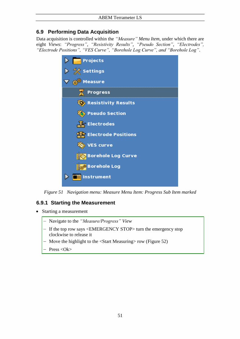
ABEM Terrameter LS
51
6.9 Performing Data Acquisition
Data acquisition is controlled within the “Measure” Menu Item, under which there are
eight Views: “Progress”, “Resistivity Results”, “Pseudo Section”, “Electrodes”,
“Electrode Positions”, “VES Curve”, “Borehole Log Curve”, and “Borehole Log”.
Figure 51 Navigation menu: Measure Menu Item: Progress Sub Item marked
6.9.1 Starting the Measurement
Starting a measurement
― Navigate to the “Measure/Progress” View
― If the top row says <EMERGENCY STOP> turn the emergency stop
clockwise to release it
― Move the highlight to the <Start Measuring> row (Figure 52)
― Press <Ok>

ABEM Terrameter LS
52
Figure 52 Start measuring command on measuring progress view
If the measurement setup involves transmitting current, that is if the measurement mode
is resistivity or IP, a warning message is issued.
Warning! Read the warning text (Figure 53) carefully before
accepting to start the measuring process, and carry out
the data acquisition accordingly!
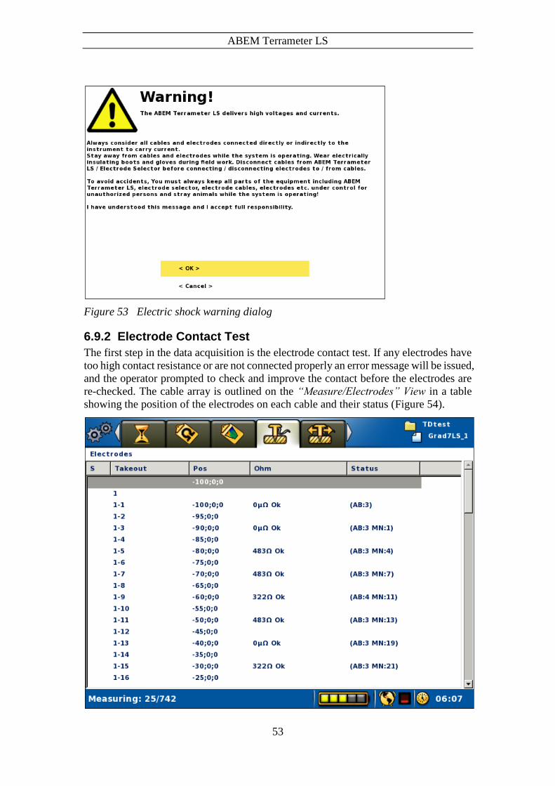
ABEM Terrameter LS
53
Figure 53 Electric shock warning dialog
6.9.2 Electrode Contact Test
The first step in the data acquisition is the electrode contact test. If any electrodes have
too high contact resistance or are not connected properly an error message will be issued,
and the operator prompted to check and improve the contact before the electrodes are
re-checked. The cable array is outlined on the “Measure/Electrodes” View in a table
showing the position of the electrodes on each cable and their status (Figure 54).

ABEM Terrameter LS
54
Figure 54 Electrode contact status view
The electrode contact test is done by the focus one method.
If the electrodes are all properly connected and well grounded, and the ground
resistance is not too high in relation to the selected current, the measuring process will
commence immediately after the electrode contact test is finished. If any electrode with
insufficient contact is detected this will be reported in the progress list and the software
will stop and wait for instruction from the operator. Navigate to the
“Measure/Electrode” View (Figure 54) and move the highlight to an electrode with no
contact. Press <Opt> and select either to exclude this electrode or to exclude all bad
electrodes (Figure 44). It is also possible to reset all electrodes that have been excluded
in order to re-check them using the same Option menu.
6.9.3 Progress and Data Viewing Options
The measuring progress is shown on the “Measure/Progress” View (Figure 55).
Figure 55 Progress view
The top of the “Measure/Progress” View shows the coordinate location of the cable
spread, and which of the cables that still remain to be used by the protocol on the present
measurement station (Figure 52 and Figure 55). If all measurements for the cable have
been completed it is removed from the list, so that only cables with remaining
measurements on the current station are listed on that line.
The left part of the Status Bar shows the progress in terms of how many measurements
that have been done out of the total number of measurements for the station.

ABEM Terrameter LS
55
When the measurement is ready the Status Bar will show “Measuring done!” and the
stop-measuring row will be replaced with a “No data points to measure” statement
(Figure 56).
All significant events that occur during the measurements process are listed in the log
on the “Measure/Progress” page, that is the large grey area. It is important to check
the different parts of the Progress View during the measurement. The logged events are
also saved in the project database, and are exported as a part of a TXT file (see chapter
7.2.2 Export a Task as a TXT (Text) File).
One type of event that can occur is measurement error. The logging of this event type
is normally preceded by a Measuring Error dialog. For more information about this
error handling see chapter 6.13 Measurement Errors.
Figure 56 Measurement ready example

ABEM Terrameter LS
56
The data can be viewed on-line in the form of a table on the “Measure/Resistivity
Results” View (Figure 57).
Figure 57 Resistivity results view
In this View the number of the measurement and key values for the transmitted signal
are displayed immediately below the header.
Note! The measurement number is not reset when creating a
new Task or switching between Tasks, it is incremented
continuously within a Project.
One measurement can have measurements for anything between one and twelve input
channels, plus the transmitter-monitoring channel (Tx).
The data for the measuring channels is displayed in a table showing channel number,
position of the electrodes used for that measurement (normally in the form cable#-
electrode#), measured quantity (delta voltage or current), normalised standard deviation
(variation coefficient), resistance, apparent resistivity, and, if applicable, chargeability.
There is a difference for the transmitter channel row where the output voltage is shown
in the resistance column.

ABEM Terrameter LS
57
Another way to display the data on-line is in the form of a pseudo section as can be seen
on the “Measure/Pseudo Section” View (Figure 58).
Figure 58 Pseudo section view
6.9.4 Pausing / Stopping the Data Acquisition
Pausing or stopping the measurement
― Move the highlight to the <Stop Measuring> row (Figure 55)
― Press <Ok>
Or
― Press <Play-Stop>
It might take a few seconds, before the measuring pause dialog is shown (Figure
59). Here it is possible to resume or stop the data acquisition process.
― Move the highlight to the appropriate row
― Press <Ok>

ABEM Terrameter LS
58
Figure 59 Measuring pause dialog
6.9.5 Deleting, Undeleting and Re-measuring Data
If a problem with the data acquisition is detected, the data acquisition process can be
stopped and data deleted so that these data points can be re-measured.
Deleting data
― Stop an ongoing measurement (6.9.4 Pausing / Stopping the Data Acquisition)
― Highlight the row in the progress list that represents the point from which data
should be re-measured
― Press <Options>
― Highlight “<Delete measurements after Mxxxx>” (Mxxxx represents a
measurement id) (Figure 60)
― Press <Ok>
Figure 60 Delete data points Option menu
This action will delete the given data points and create a new entry in the progress list,
“Deleted ‘Measurement Mxxx,…,Mxxx n=xxx’” (Figure 61). The Mxxx part shows a
span of measurement ids that are deleted and the n value is the number of data points
deleted.

ABEM Terrameter LS
59
Figure 61 Example of deleted data points
Undeleting data
― Stop an ongoing measurement (6.9.4 Pausing / Stopping the Data Acquisition)
― Highlight the “Deleted ‘Measurements…” row in the progress list that
represents the point from which data should be undeleted
― Press <Options>
― Highlight “<Undelete ‘Measurements Mxxx,…,Mxxx n=xxx’>” (Mxxxx
represents a measurement id) (Figure 62)
― Press <Ok>
Figure 62 Undelete/Delete data points Option menu

ABEM Terrameter LS
60
The command will also create a new entry, this time called “Undeleted ‘Measurement
Mxxx,…,Mxxx n=xxx’”, with the same numbers as the Deleted entry (Figure 63).
Figure 63 Example of undeleted data points
A new measurement can be started when data points have been deleted or undeleted.

ABEM Terrameter LS
61
6.10 Vertical Electrical Sounding
Vertical Electrical Sounding, VES, can be carried out using a set of standard VES cables
and by moving the electrodes manually. Four electrodes are connected via cables to the
C1, C2, P1 and P2 connectors on the contact panel. The “Measure/Electrodes” View
for a VES Task will consequently look similar to the one shown in Figure 64.
The LS instrument is said to be in VES mode when the active Task is a VES Task, that
is the Task was created with a VES protocol.
Figure 64 The Electrodes View in VES mode
The electrode positions are pre-defined in a measurement protocol and thus the
electrode coordinates will automatically be saved together with the measured data. The
measurement protocols must be written in a special format (see Appendix 11.9
“Protocol Files in XML-format for VES”).
In VES mode there will be primarily three Views involved:
- The “Measure/Progress” View (Figure 65) will be used to start and stop
measurements as usual. The active electrode position, that is the electrode
position to be measured, can also be set from this View.
- The “Measure/Electrode Positions” View (Figure 66) displays a list of all the
electrode positions of the active Task. The active electrode position can be set
and a new temporary electrode position can be created from this View.
- The “Measure/VES Curve” View (Figure 71) displays a sounding curve of the
made measurements

ABEM Terrameter LS
62
6.10.1 Managing Electrode Positions
Electrode positions for a VES Task are handled as “MN/2 and AB/2” numbers. These
numbers will be multiplied with the minimum electrode spacing selected. The electrode
position to be measured, the active position, can be changed. It is in this way possible
to step through all the electrode positions that are pre-defined in the protocol file.
Figure 65 The Progress view in VES mode
In VES mode a line with a “MN/2 and AB/2” electrode position will be shown on the
Progress View (Figure 65). This is the active electrode position.
Changing the active electrode position from the Progress View
― Highlight the “MN/= x AB/= x” row in the progress list
― Press <Left> and/or <Right>
Possible new electrode positions added in the Electrode Positions View (see below) can
also be set to the active electrode position in this way.

ABEM Terrameter LS
63
Figure 66 The Electrode Positions view in VES mode. Highlight on the second row
and active electrode position marker on the fourth row
The Electrode Positions View (Figure 66) lists all the electrode positions from the
protocol file. The dark yellow arrow is placed on the line that corresponds to the active
electrode position. This electrode position is the one that is shown on the second row
of the Progress View (Figure 65). The Electrode Positions View will be empty when
the instrument is not in VES mode.
Changing the active electrode position from the Electrode Positions View
― Highlight the wanted electrode position in the list
― Press <Ok>
A new electrode position can be created for use during the measurement session.
Note! Please observe that electrode positions created this way
are not saved to disk, and thus will be lost when the
instrument is turned off or when the active Project or
Task is changed
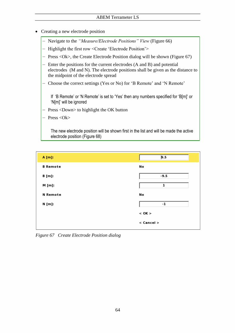
ABEM Terrameter LS
64
Creating a new electrode position
― Navigate to the “Measure/Electrode Positions” View (Figure 66)
― Highlight the first row <Create ‘Electrode Position’>
― Press <Ok>, the Create Electrode Position dialog will be shown (Figure 67)
― Enter the positions for the current electrodes (A and B) and potential
electrodes (M and N). The electrode positions shall be given as the distance to
the midpoint of the electrode spread
― Choose the correct settings (Yes or No) for ‘B Remote’ and ‘N Remote’
If ‘B Remote’ or ‘N Remote’ is set to ‘Yes’ then any numbers specified for ‘B[m]’ or ‘N[m]’ will be ignored
― Press <Down> to highlight the OK button
― Press <Ok>
The new electrode position will be shown first in the list and will be made the active electrode position (Figure 68)
Figure 67 Create Electrode Position dialog

ABEM Terrameter LS
65
Figure 68 Result of Create Electrode Position
6.10.2 Performing a VES Measurement
Starting a VES measurement
― Set the active electrode position as described above
― Make certain that the electrodes have actually been moved to the desired
physical position and check that everyone stands clear of the electrodes and
cables
― Navigate to the “Measure/Progress” View. Quickest way to do this is to press
<Play/Pause>
― Highlight the “<Start Measuring>” row in the progress list
― Press <Ok>
― The “Electric Shock Warning” will now be displayed
Warning! Do not press <OK> until it is verified that no person or
animal is touching any part of the electrode cables,
connectors or electrodes!

ABEM Terrameter LS
66
Figure 69 shows the Progress View during a VES measurement. The measurement can
be paused, stopped and resumed as described in chapter 6.9.4 Pausing / Stopping the
Data Acquisition.
Note! In case any person or animal approaches the electrode
layout current transmission must be stopped
immediately with the Emergency Stop Button
Figure 69 Progress view in VES mode during on-going measuring
When the measurement is ready the Status Bar will show “Measuring done!” and the
stop-measuring row will be replaced with a “No data points to measure” statement
(Figure 70).
Figure 70 Part of the Progress view in VES mode after measuring a data point
Measuring the next data point
― Make sure the “MN/”= x AB/”= x” row is highlighted
― Press <Right>
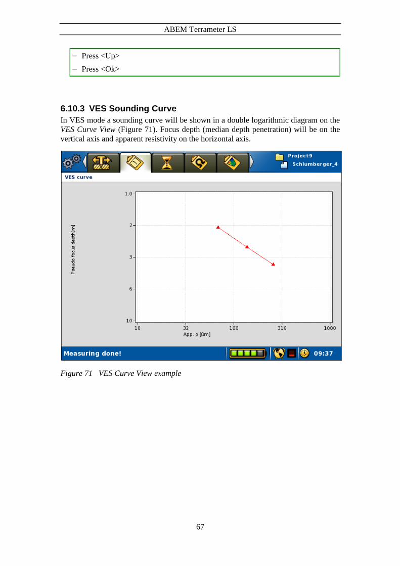
ABEM Terrameter LS
67
― Press <Up>
― Press <Ok>
6.10.3 VES Sounding Curve
In VES mode a sounding curve will be shown in a double logarithmic diagram on the
VES Curve View (Figure 71). Focus depth (median depth penetration) will be on the
vertical axis and apparent resistivity on the horizontal axis.
Figure 71 VES Curve View example

ABEM Terrameter LS
68
6.11 Full Waveform Data
Internally the instrument records data with the sample rate set in the “Settings/Receiver
settings” View. This data is filtered and averaged in order to provide the measured
voltages, resistances, and chargeability’s that are displayed and saved. By default the
full waveform data with microsecond resolution is not saved, but it is possible to do so
in order to make it possible to analyse the received signals in detail afterwards.
Saving full waveform data opens possibilities to view and analyse the received signals
in detail afterwards. This makes it possible to identify and understand the occurrence
of for example excessive power line network noise, telluric noise, signal disturbances
caused by cable coupling, etc. This in turn may be useful as input for how to optimise
the data acquisition process, especially for IP measurements which are more sensitive
to noise than resistivity measurements.
Chapter 5.2.2 Data Acquisition Settings describes how this feature is turned on or off.
Be aware that turning the feature on means saving large amounts of data that can fill
the disk, and will take significant time to transfer from the instrument to a PC. It is not
recommended to attempt to copy a Project containing full waveform data to a USB disk,
as it will take a long time.
6.12 Borehole Logging with Terrameter SAS LOG
The Terrameter SAS LOG logging system can be used together with the Terrameter LS
system. The current SAS LOG is intended for logging depths of down to 300 meters.
This simple logging system makes it possible to delineate formation boundaries with
regard to infiltration, porosity and permeability by means of self-potential and
resistivity measurements. Under favourable circumstances, water flow boundaries can
be detected by measuring temperature changes. Moreover, the resistivity of the water
can be measured in situ so that the total amount of total dissolved solids (TDS) can be
estimated. Zones of high salinity can thus be localized and sealed off by means of casing
and cementing.

ABEM Terrameter LS
69
6.12.1 The Hardware
Backpacking frame
Logging cable
Connector for LS control cable Electronic
unit
Probe
Figure 72 Terrameter SAS LOG 300 with backpacking frame
The SAS LOG 300 (Figure 72) consists of a 300 m long logging cable with a logging
probe and a backpacking frame. On the frame is an electronic unit mounted as well as
connectors for the Current Return / Potential Reference and a connector for connecting
to the Terrameter LS. The connectors are on the backside of the backpacking frame
(Figure 73).
Figure 73 Connectors on the backside of the backpacking frame

ABEM Terrameter LS
70
The logging cable has seven nylon-insulated conductors and a polyurethane jacket. A
Kevlar stress member is incorporated. The cable is marked at 1 m intervals, starting at
the logging probe shoulder. Three cylindrical takeouts are located 5.6 m, 1.2 m and 0.4
m upwards from the probe shoulder.
Figure 74 Logging probe with close-up of probe bottom
The stainless steel upper end (shoulder) of the logging probe, serves as electrode 0 m
(Figure 74). The lower inside end of the probe - the chamber - has one ring electrode,
-0.4 m and one electrode in the centre, the chamber electrode. The centre electrode also
contains the temperature transducer. The end of the chamber is set at an angle to
improve circulation of fluid in the chamber as the probe moves. Three holes in the
chamber wall permit air to escape, thus ensuring good contact with the fluid.
A multi function cable, 33 0020 11, connects the SAS LOG 300 to Terrameter LS. The
SAS LOG is fully governed from the Terrameter LS.

ABEM Terrameter LS
71
Referential potential electrode
Return current
electrode
> 50 m > 50 m
Takeouts
Probe
Probe shoulder electrode
Ring and chamber electrode
Backpacking frame
Multi function cable
Logging cable
Figure 75 Overview of cabling and layout of the electrodes
The return current connector is connected to a return current electrode (ABEM stainless
steel electrode) placed not less than 50 m from the well to be surveyed.
The potential reference connector is connected to a reference potential electrode
(ABEM stainless steel electrode) not less than 50 m from the well and in the opposite
position from the return current electrode.
Note! Even though there is a test function for testing the
ground connection of these remote electrodes, great care
should be exercised when installing them to ensure
reliable connection to the ground.
Directly after power on, the LOG will perform a self-check, which takes a few seconds.
During the self-check a few clicks will be heard from the electronic unit in the
backpacking frame.

ABEM Terrameter LS
72
Note! During logging operation there should be no connections
to C1-C2 and P1-P2 terminals on Terrameter LS.
6.12.2 Quick Look: A Normal Borehole Logging Session
A short introduction to a normal borehole logging session with references to the
relevant chapters.
Set up the hardware (see 6.12.1)
Do an electrode test (see 6.12.5.2)
Do a water level check (see 6.12.5.4)
Do a depolarization (see 6.12.5.3)
Set up temperature and SP to be measured in down-logging (see 5.2.2)
Set up resistivity and IP to be measured in up-logging (see 5.2.2)
Do down logging (temperature and SP recorded) (see 6.12.5.5)
Do up logging (resistivity and IP recorded) (see 6.12.5.5)
Save the recorded data as LAS and perform post processing on it (see 6.12.6)
6.12.3 About Borehole Logging Measurement Modes
The Terrameter LS uses the concept of measurement modes to facilitate different
operations during a borehole logging session. Three different types of operations are
covered:
Preparation (electrode test, depolarize, level check)
Down-and-up logging (down, up)
Single value measurement, one for each measurement type (temperature, SP
voltage, short normal, long normal, long lateral, fluid resistivity).
An overview of the measurement modes:
Down Downward logging where values of up to six different
measurement types are recorded for each step
Up Upward logging where values of up to six different
measurement types are recorded for each step
Electrode Test Test of the remote C and P logging electrodes
Depolarize Equalizes built-up transmitter potentials prior to SP
measurements
Level Check Find the water level
Temperature Only temperature is measured for the current probe level
ABEM Terrameter LS
73
SP Voltage Only SP voltage is measured for the current probe level
Short Normal
(Res & IP)
Only short normal is measured for the current probe level
Long Normal
(Res & IP)
Only long normal is measured for the current probe level
Long Lateral (Res
& IP)
Only long lateral is measured for the current probe level
Fluid Resistivity Only fluid resistivity is measured for the current probe level
6.12.4 About Borehole Logging Measurement Types
6.12.4.1 Temperature and SP Voltage
Normally temperature and SP are logged at the first run downwards the well, in the
unstirred water and with no polarization effects residing from resistivity measurements.
When assuming high precision for temperature gradient studies, ample time must be
allowed to permit the probe to reach thermal equilibrium vis-à-vis the fluid. Move the
probe slightly up and down a few times while waiting for equilibrium to be established.
Temperature logging should be the first log at each station, since undisturbed water is
required.
To reduce electrode polarization, attributable to previous resistivity measurement or
long storage in air, the electrodes should be depolarized before SP logging starts.
Note! Resistivity or IP should not be measured during a SP
logging run.
6.12.4.2 Short Normal
Current is injected via the shoulder electrode (0 m). The corresponding response voltage
is measured between the ground potential reference and the ring electrode at the bottom
of the probe. The Terrameter LS will display the resistivity of the surrounding medium.
6.12.4.3 Long Normal
Current is injected via the 1.2 m takeout while the potential is measured at the ring
electrode at the bottom of the probe. The Terrameter LS will then display the resistivity
of the surrounding medium.
6.12.4.4 Long Lateral
Current is injected via the 5.6 m takeout while the potential is measured between the
ring electrode at the bottom of the probe and the 0.4 m takeout.
The Terrameter LS will automatically perform the necessary conversions, and display
the resistivity of the surrounding medium, measured with the ”Long Lateral”
configuration.

ABEM Terrameter LS
74
6.12.4.5 Fluid Resistivity
The current is injected via the ring electrode, while the potential is measured between
the shoulder electrode (0 m) and the chamber electrode. The fluid resistivity is
calculated, presented on the display, and saved in the Terrameter LS. In case of small-
diameter wells a correction is needed. The table below lists the correction factors to be
used. The calculation is not done to the stored values.
6.12.4.6 Fluid resistivity and estimation of TDS
The Terrameter LS can be used to measure the resistivity of a fluid, thus enabling you
to determine the Total Dissolved Solids (TDS) in the fluid.
Resistivity is a function of water temperature, and a standard temperature (usually 25C)
must be specified for reporting resistivity or conductivity. For resistivity, the
approximate conversion formulas for common standard temperatures are:
18 = T (0.62 + 0.021 T)
20 = T (0.58 + 0.021 T)
25 = T (0.48 + 0.021 T)
where T is the temperature in C in the range 5 - 50 C and T the measured fluid
resistivity at the temperature T.
Concentrations by weight
Concentrations of the common ions found in ground water are often reported by weight
in parts per million (ppm). One ppm defines one part by weight of the ion to a million
parts by weight of water, and it is numerically equivalent to milligrams per litre. TDS
is also reported as ppm.
The TDS estimation for an average of natural ground waters is:
TDSppm = 6400/25 where 25 is in m.
Conductance is sometimes preferred for the estimation of TDS (rather than resistance,
its reciprocal) since it increases with salt content. Conductance is measured in Siemen
(= S = mho = (m)-1), but for comparative purposes results are usually reported as
electrical conductivity (EC), which is measured in S/m. Since most ground waters have
conductivities of much less than 1 S/m (and since this method is often used to determine
the TDS of ground water), it is often more convenient to use mS/m.
Well diameter in mm. Correction
factor
50 - 60 1.08
60 - 70 1.06
80 - 90 1.03
90 - 100 1.01

ABEM Terrameter LS
75
6.12.5 Operating the logging system
Assuming basic familiarity with the Terrameter LS (see chapter 3 The User Interface),
these would be the steps to set up for a borehole logging session:
Create a new Project
Create a new Task:
a. Select the SASLOG spread. Protocol will be set to Borehole Logging
b. Set the Electrode Spacing Z to the desired minimum distance between
each measurement to be done in the borehole
Setup the desired parameters for your borehole logging in the different Settings
Views (see chapter 5.2.2). For example, if both resistivity and IP is desired, choose
RES, IP. Use the “Settings/Borehole Log Settings” View to define which
measurement types to record during the down and up parts of a borehole logging.
For normal borehole logging (see chapter 6.12.2 Quick Look: A Normal Borehole
Logging Session) it is recommended that each session be started with these modes, if
applicable, and in this order:
Electrode Test
Level Check
Depolarize
The “Measurement/Borehole Log” View (Figure 76) is where most of the user
interaction is done for borehole logging sessions.

ABEM Terrameter LS
76
Figure 76 Borehole Log View with Depolarize selected
Basic user interactions of the “Measurement/Borehole Log” View is described in the
first subchapter below with the subsequent chapters describing the different
measurement modes.
6.12.5.1 Basic Borehole Log User Interaction
These interactions will only be described in detail here.
Selecting a measurement mode
― Highlight the “Measure mode” row
― Press <Left> and/or <Right> until the wanted mode is selected
Starting a measurement
― Highlight the “<Start>” row
― Press <OK>
Stopping a measurement
― Highlight the “<Stop>” row
The <Start> row will change to <Stop> when a measurement is ongoing
― Press <OK>
Manually increasing or decreasing the probe level with the Step Distance (see page
41)
― Highlight the “<Move Up>” or “<Move Down>” row
― Press <OK>
The Probe level will be increased or decreased the current step distance (the Minimum Electrode Spacing Z multiplied with the step up or down multiplier)

ABEM Terrameter LS
77
Editing the probe level
― Highlight the Probe level row
― Press <OK>
The numeric keyboard emulator will be shown
― Enter the wanted probe level, see chapter 3.5.2 The Keyboard Emulators
Editing the fluid level
― Highlight the Fluid level row
― Press <OK>
The numeric keyboard emulator will be shown
― Enter the wanted fluid level, see chapter 3.5.2 The Keyboard Emulators
Note! The Down and Up measurement modes have automatic
updating of the probe level after each measurement
The <Start> row will change (Figure 77) if the Emergency Stop button has been
depressed (the secure locked position). In this case nothing will happen if the
Emergency Stop row is selected and <OK> is pressed.
Figure 77 Emergency Stop (part of the Borehole Log View shown)
For all measurement modes where current will be transmitted there will be a warning
shown, see chapter 6.9.1 Starting the Measurement.

ABEM Terrameter LS
78
Warning! Read the warning text (Figure 53) carefully before
accepting to start the measuring process, and carry out
the data acquisition accordingly!
6.12.5.2 Electrode Test
Warning! Current will be led through the probe as well as the C
and P electrodes during the electrode test.
Running an electrode test
― Select the Electrode Test mode
― Start a measurement
― Follow the instruction on the first dialog (Figure 78)
― Press <OK>
― When the electrodes have been tested the result will be displayed with the
second or third dialog respectively (the resistance values will differ)
― Press <OK> to finish the test
Figure 78 The Electrode Test dialogs
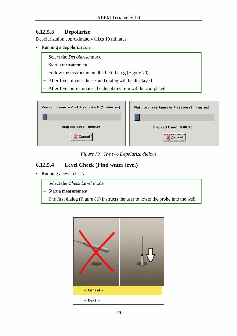
ABEM Terrameter LS
79
6.12.5.3 Depolarize
Depolarization approximately takes 10 minutes.
Running a depolarization
― Select the Depolarize mode
― Start a measurement
― Follow the instruction on the first dialog (Figure 79)
― After five minutes the second dialog will be displayed
― After five more minutes the depolarization will be completed
Figure 79 The two Depolarize dialogs
6.12.5.4 Level Check (Find water level)
Running a level check
― Select the Check Level mode
― Start a measurement
― The first dialog (Figure 80) instructs the user to lower the probe into the well

ABEM Terrameter LS
80
Figure 80 First Check level dialog
― Highlight the <Next> row
― Press <OK>
― A level indicator dialog is shown (Figure 81). The picture on the dialog will
change automatically depending on if water is detected or not, respectively
showing that the probe should be lowered or raised to more accurately find the
water level.
― Repeat the lowering and raising of the probe with smaller and smaller distance
increments until the water level is sufficiently correct.
― Highlight the <Next> row
― Press <OK>
― Edit the Fluid Level with the meter marking on the logging cable
Figure 81 Level Indicator dialog
6.12.5.5 Down and Up measurement modes
These are meant to be the normal measurement modes for borehole logging.
These modes help to automate the logging session to a certain degree by automatically
updating the Probe Level for the next measurement, indicating to the user what depth
to lower or raise the probe to.

ABEM Terrameter LS
81
Running down logging
― Select the Down mode
― Do a measurement
― Note the new Probe Level and lower the probe accordingly
Repeat these two steps until the desired depth is reached
Running up logging
― Select the Up mode
― Do a measurement
― Note the new Probe Level and raise the probe accordingly
Repeat these two steps until the desired depth is reached
Results are displayed in the table to the right (Figure 82).
Figure 82 Borehole Log View – Table filled with measured values
6.12.5.6 Single value modes
Facilitates doing single value measures when appropriate. For example when values
might need to be measured one more time.

ABEM Terrameter LS
82
Running single value borehole logging
― Select the wanted single value mode
― Do a measurement
The measured value will be shown in the table
Note! <Move Up> and <Move Down> can be used before
and/or after doing a single value measurement
6.12.6 Working With Borehole Logging Data
Terrameter LS has a View where the borehole logging data can be viewed as curves,
the “Measurement/Borehole Log Curve” View (Figure 83).
Figure 83 Borehole Log Curve View
Legends used for the curves:
Temperature Red squares
SP Voltage Green triangles
Short Normal Blue circles
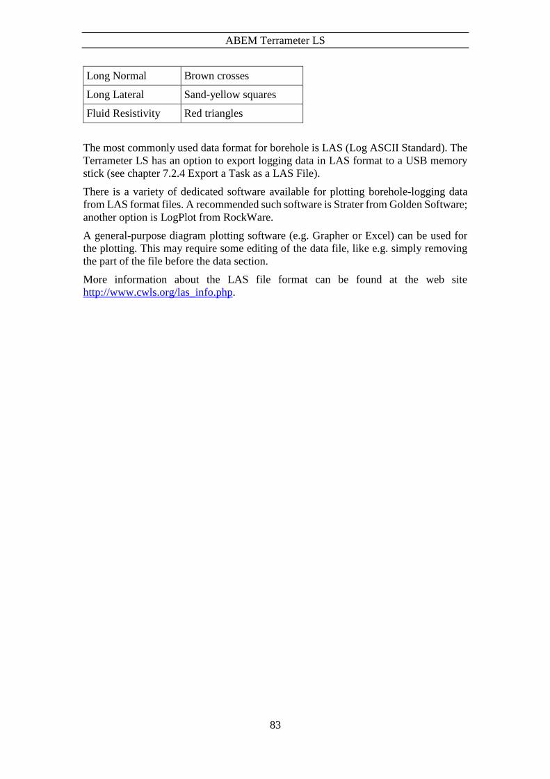
ABEM Terrameter LS
83
Long Normal Brown crosses
Long Lateral Sand-yellow squares
Fluid Resistivity Red triangles
The most commonly used data format for borehole is LAS (Log ASCII Standard). The
Terrameter LS has an option to export logging data in LAS format to a USB memory
stick (see chapter 7.2.4 Export a Task as a LAS File).
There is a variety of dedicated software available for plotting borehole-logging data
from LAS format files. A recommended such software is Strater from Golden Software;
another option is LogPlot from RockWare.
A general-purpose diagram plotting software (e.g. Grapher or Excel) can be used for
the plotting. This may require some editing of the data file, like e.g. simply removing
the part of the file before the data section.
More information about the LAS file format can be found at the web site
http://www.cwls.org/las_info.php.
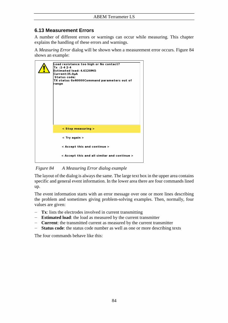
ABEM Terrameter LS
84
6.13 Measurement Errors
A number of different errors or warnings can occur while measuring. This chapter
explains the handling of these errors and warnings.
A Measuring Error dialog will be shown when a measurement error occurs. Figure 84
shows an example:
Figure 84 A Measuring Error dialog example
The layout of the dialog is always the same. The large text box in the upper area contains
specific and general event information. In the lower area there are four commands lined
up.
The event information starts with an error message over one or more lines describing
the problem and sometimes giving problem-solving examples. Then, normally, four
values are given:
― Tx: lists the electrodes involved in current transmitting
― Estimated load: the load as measured by the current transmitter
― Current: the transmitted current as measured by the current transmitter
― Status code: the status code number as well as one or more describing texts
The four commands behave like this:

ABEM Terrameter LS
85
― Stop measuring: The measurement stops. Works just like the stop command on the
Progress View
― Try again: The measurement is restarted from the failed data point. The error dialog
will be shown again if the error persists
― Accept this and continue: The data point is marked as failed and the measurement
is resumed with the next data point. The error dialog will be shown again for the
same type of error occurring later
― Accept this and all similar and continue: The data point is marked as failed and
the measurement is resumed with the next data point. The error dialog will not be
shown again for the same type of error occurring later in this measurement
A list of error messages follows:
Error message Comment
Emergency stop The Emergency Stop Button has been
pressed
Power source low voltage Check the internal and/or external
battery
Power source low capacity Check the internal and/or external
battery
Load resistance too high or No contact? Contact between LS and electrode(s)
might be bad. Check all contacts and
cables
Or
Contact between electrode(s) and
ground might be bad. Moisten the
ground around the electrode(s) with
salted water
No contact. Can not transmit current See Load resistance too high or No
contact (above)
Transmitter stopped due to unexpected high
power loss. Probable causes: A sudden drop
in resistance or a highly inductive load. Try
to reduce the maximum current
Stopped to prevent the transmitter
from being damaged. Try the proposed
action

ABEM Terrameter LS
86
Here are some examples of the text area information for different measurement errors:

ABEM Terrameter LS
87
7 Measurement Post-Production
7.1 Repack the LS system
Cleaning and repacking the equipment properly will give your instrument a longer life.
Below we have tried to specify key areas for maintenance of this instrument.
Check that all pieces of equipment is collected from the field
Clean each part thoroughly, if needed by washing and drying
Always store the instrument dry in its original travelling package
7.2 Export Measurement Data
To enable analysis and processing of the collected measurement data it can be exported.
There are two ways to do this, either by exporting directly to a USB memory stick
connected to the LS, which is described in the following subchapters, or by using the
Terrameter LS Toolbox.
Note! It is strongly recommended for users to always transfer
the Project database and store it for future use. It may
turn out that more information than the standard export
formats provide becomes desirable. Also, in case of
need of support from ABEM’s support department you
are likely to be asked to send the Project database file as
it contains essential information for instrument
diagnostics.
7.2.1 Export a Task as a DAT File
Data can be exported as a DAT-file (Res2dinv compatible format) to a PC via a USB
memory stick, for analysis, processing and presentation. Connect the USB device to the
Terrameter LS.
Export as a DAT file
― Navigate to the “Projects/Task List” View
― Highlight the Task to export
― Press <Options>
― Highlight <Export Task as DAT> (Figure 85)
― Press <Ok>

ABEM Terrameter LS
88
Figure 85 Task options menu
Confirm that you want to export to the USB memory device (Figure 86).
Figure 86 Export task to DAT confirmation dialog
7.2.2 Export a Task as a TXT (Text) File
Export as a TXT file
― Navigate to the “Projects/Task List” View
― Highlight the Task to export
― Press <Options>
― Highlight <Export task as TXT> (Figure 87)
― Press <Ok>

ABEM Terrameter LS
89
Figure 87 Task options menu
Confirm that you want to export to the USB memory device (Figure 88).
Figure 88 Export task to TXT confirmation dialog
7.2.3 Export a Task as a USF File
Export as a USF file
― Navigate to the “Projects/Task List” View
― Highlight the Task to export
― Press <Options>
― Highlight <Export task as USF> (Figure 89)
― Press <Ok>

ABEM Terrameter LS
90
Figure 89 Task options menu
Confirm that you want to export to the USB memory device (Figure 90).
Figure 90 Export task to USF confirmation dialog
7.2.4 Export a Task as a LAS File
Export as a LAS file
― Navigate to the “Projects/Task List” View
― Highlight the Task to export
― Press <Options>
― Highlight <Export task as LAS> (Figure 91)
― Press <Ok>
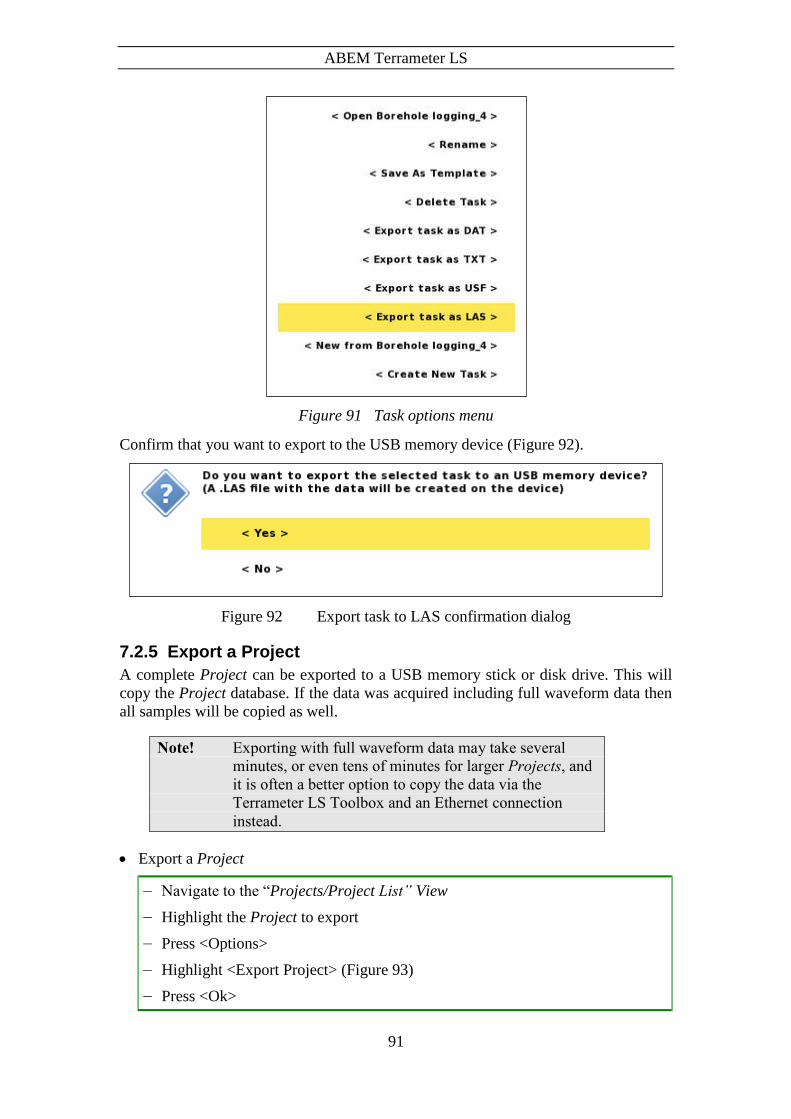
ABEM Terrameter LS
91
Figure 91 Task options menu
Confirm that you want to export to the USB memory device (Figure 92).
Figure 92 Export task to LAS confirmation dialog
7.2.5 Export a Project
A complete Project can be exported to a USB memory stick or disk drive. This will
copy the Project database. If the data was acquired including full waveform data then
all samples will be copied as well.
Note! Exporting with full waveform data may take several
minutes, or even tens of minutes for larger Projects, and
it is often a better option to copy the data via the
Terrameter LS Toolbox and an Ethernet connection
instead.
Export a Project
― Navigate to the “Projects/Project List” View
― Highlight the Project to export
― Press <Options>
― Highlight <Export Project> (Figure 93)
― Press <Ok>

ABEM Terrameter LS
92
Confirm that you want to export to the USB memory device (Figure 94).
Figure 93 Project options menu
Figure 94 Export Project confirmation dialog
7.3 Delete a Project
Deleting a Project
― Navigate to the “Projects/Project List” View
― Highlight the Project to delete
― Press <Options>
― Highlight <Delete Project> (Figure 95)
― Press <Ok>
Confirm that you want to delete the Project (Figure 96).
Warning! This will delete all data in the Project permanently!
Figure 95 Project options menu
Figure 96 Delete Project confirmation dialog

ABEM Terrameter LS
93
8 Testing, Diagnostics and Error Search
Terrameter LS has built-in self-test and calibration of the major functions, including
input boards, transmitter and relay switch. Test results are automatically logged for
quality assurance purposes, and any malfunction reported to the operator. Temperature
and power supply voltage is constantly monitored and logged.
8.1 Self Test
A self-test can be carried out which will run voltage measurements of internal
references and do offset measurement, plus run resistivity measurements on test loads
of 1.5 Ohm and 33 kOhm. The test is carried out in the following way:
Disconnect all electrode cables or other devices connected to the input panel.
Navigate to the “Settings/Receiver” View and set:
- “Mode” to “RES”
Navigate to the “Settings/Transmitter” View and set:
- “Electrode Test” to “No”
- “Minimum Current” to 1mA
Create a new Task and select the spread “LS internal” and the protocol “Selftest”.
Start the measuring procedure.
After measuring is completed the result can be exported as a text-file for inspection
and as documentation. Voltage measurements are taken on the built-in reference
voltages with different measurement ranges, and the nominal values are shown in
the text-file. Furthermore resistance measurements are taken on built-in resistors
(note that it is not any precision resistors deviations in the range 10% from the
nominal value are normal).
“Max Current” can be selected according to available power supply. If the power is
limited it is ok with for instance 50 mA, but if a more competent power supply is used
up to 2500mA can be selected and then a more complete self-test will be achieved.
Note! This test requires at least 32 switch channels and it may
not work on individuals delivered early.
8.2 Cable Continuity Test
A cable continuity test can be carried out in the following way:
High voltages will be present on the electrode take-outs during
this test. Make sure nobody and nothing touches the electrode
cable(s) during the cable continuity test.
Connect one electrode cable with one end to “Electrode 1-32” and the other end to
“Electrode 33-64”. (Not for VES edition). Make sure that the electrode take-outs do
not touch each other or anything else

ABEM Terrameter LS
94
Navigate to the “Settings/Transmitter” View and make sure that “Electrode Test”
is set to “No”
Create a new Task and select the spread “CableTest” and the protocol
“CableContinuityTest”
Start the measuring procedure. If the cable is Ok it should be possible to take all
measurements of the protocol. If there is any problem transmitting current there is
a problem with the cable.
Repeat the procedure for all electrode cables.
After measuring is completed the result can be exported as text-file for inspection
and as documentation.
8.3 Cable Isolation Test
High voltages will be present on the electrode take-outs during
this test. Make sure nobody and nothing touches the electrode
cable(s) during the cable isolation test.
A cable isolation test can be carried out in the following way:
Figure 97 Two cables connected for cable isolation test
Electrode cables to be tested shall be connected to the “Electrode 1-32” or the
“Electrode 33-64” connector
One or two electrode cables can be tested at the same time. If two cables are to be
tested then one cable shall be connected to the “1-32” connector and the other cable
to the “33-64” connector
If only one cable is to be tested then using the “1-32” connector will produce the
test result at the top of the electrode list (see below)
Note! Only one end of the cables to be tested shall be
connected to the instrument. The other end must be
unconnected.
Make sure that nothing else is connected to the cable and that the electrode take-
outs do not touch each other or anything else.
Navigate to the “Settings/Transmitter” View and make sure that “Electrode Test”
is set to “Focus One”
Create a new Task and select the spread “CableTest” and the protocol
“CableIsolationTest”
Cable 2
Cable 1

ABEM Terrameter LS
95
Start the measuring procedure, which will start with the electrode contact test
Navigate to the “Measure/Electrodes” View to check the result of the test. If the
cable is Ok there should not be contact for any of the electrodes on the cable(s), that
is the text in the Ohm column should read ‘*No contact*’ for all electrodes. If there
is any connection (see Figure 98) there is a problem with the cable.
Figure 98 The Electrodes view showing the result for a faulty cable
8.4 Remote Diagnostics
The Terrameter LS can be connected to ABEM for remote diagnostics over a VPN
(Virtual Private Network). To connect the instrument to a VPN you need a standard
Ethernet based TCP/IP LAN (Local Area Network) that is connected to the Internet.
The instrument is connected to the LAN with a RJ-45 cable. Connect the instrument to
the network before it is switched on.
If the LAN has a DHCP service, the instrument will acquire an IP number and most
likely the other required network settings from the DHCP server when the network
service starts. Note that the DHCP server must allow unregistered MAC addresses. If it
does not, the instrument’s MAC address must be registered in it. Please contact your
local network administrator if this is necessary. To find the instrument’s MAC, see the
“Instrument/Network” View.
Restrictions: The LAN router or firewall must not block outgoing traffic on port 1194,
and must allow incoming traffic that is initiated from inside the LAN to be returned to
the instrument. Further, if the LAN is using NAT, it must not use the private IP network
10.17.23.x since the VPN will be using it. Most office LANs will meet these
specifications.

ABEM Terrameter LS
96
If you are not familiar with the terminology in this section, and experience problems
with the connection, please contact your local network administrator.
The instrument automatically tries to establish a secure network connection to the
ABEM support server. This will succeed if the instrument has a network connection
that allows VPN communication with the ABEM office www.abemoffice.com and port
1194.
A successful connection will add a tun0 line on the network information page:
This address is provided to the Terrameter LS from the ABEM server
Please note: Some countries/companies have firewall rules that blocks access to this
type of service.
Figure 99 Remote diagnostics over VPN
8.5 In Case of Malfunction
In case of malfunction please carry out applicable tests as described in this manual. If
it is not possible to find the cause of the problem, follow the instructions in Section 8.4
Remote Diagnostics to connect the instrument to ABEM’s technical support, and send
a description of the problem to via e-mail to [email protected].
Should a fault occur that is not correctable on site, please send full details to ABEM. It
is essential that instrument type and serial number is included and, if possible, the
original ABEM delivery number. On receipt of this information, disposition
instructions will be sent by return. Freight to ABEM must be prepaid. For damage or
repairs outside the terms of the Warranty, ABEM will submit an estimate before putting
the work in hand.
Be sure to fill in the warranty registration card (included with the equipment) correctly
and return it to ABEM promptly. This will help us process any claims that may be made
under the warranty. It will also help us keeping you informed about for instance free
software upgrades. ABEM welcomes your response at any time. Please let us know
your name and address, and the serial number of the instrument.
Terrameter LS
Router
Server
Router
Customer Network ABEM
Internet
Allow outgoing traffic to www.abemoffice.com
port 1194

ABEM Terrameter LS
97


ABEM Terrameter LS
99
9 Appendix A. Technical Specification
9.1 General
Casing Rugged Aluminium case meets IEC IP 66
Computer Embedded ARM 9, 200 MHz
GPS 20 channels SirFstarIII chip
Display 8,4” Active TFT LCD, full colour, Daylight
visible
I / O ports 2 x KPT 32 p for imaging, (1 KPT for VES)
AUX, Interconnect (not for VES edition)
C1, C2, P1(ch1), P2(ch1),
2 x USB, RJ45 for LAN
Service point Accessible through Internet
Memory Capacity 8 GB
Power Internal NiMH 12 V power pack or
Optional External 12 VDC battery
Temperature range - 20 oC to + 70 oC operating1,2
- 30 oC to + 80 oC storage3 Note 1: The performance of the LCD is not guaranteed
below 0 oC
Note 2: Measuring speed may be reduced in high
ambient temperature combined with high output power
Note 3: Non condensing
Dimensions (W x L x H) 39 x 21 x 32 cm
Weight 12 kg
9.2 Measuring
Resistivity YES,
SP YES
IP YES
Dynamic Averaging 24 bit A/D conversion
Cycle time User selectable from 0.4sec to 32 sec.
Corresponds to a pulse time from 0.1 s to 8 s
Stacking Displayed automatically on screen, number of
stacks user selectable
IP Windows Arbitrary windows flexibility configured to
power line frequencies
9.3 Receiver
Number of channels 4 – 12 input (+ 2 for TX monitoring)
Isolation All channels are Galvanically separated
Input Voltage Range + / - 600 V
Input Impedance 200 M, 30 M and 20 M
Precision 0.1 %
Accuracy 0.2 %
Resolution 3 nV at 1 sec integration
Linearity 0.005 %
Range Auto range of measurement

ABEM Terrameter LS
100
±2.5V, >100M ±15V, 30 M (fully
differential), ±600V, 20 M
Flat Frequency Response better than 1 % up to 300 Hz
9.4 Transmitter
Output power 250 W
Current transmission True Current Transmitter
Output Current Accuracy better than 0.4 %
Maximum Output Current 2500 mA
Maximum Output Voltage + / - 600 V (1200 V peak to peak)
Instant Polarity Changer YES
Accuracy 0.4 %
Precision 0.1 %
Self Diagnostics Temperature, Power dissipation monitoring
Safety Emergency Interrupter easily accessible
Tx Monitor Full waveform monitored
Accuracy 0.2 %
Precision 0.1 %
9.5 Relay Switch
Switching matrix Internal 10 X 64
Roll-along YES full coverage, both 2 & 3D. All 84 take-
outs in an ABEM standard four-cable array are
active for roll-along
Array types Default Multiple gradient, dipole-dipole, pole-dipole,
pole-pole, Wenner, Schlumberger, etc.
Electrode Test YES, Focus One
9.6 Software & Communication
Terrameter LS is controlled using the incorporated Firmware. It supports Multi-
Electrode Survey Systems for 2D & 3D for Resistivity, IP & SP Imaging & Monitoring.
It has a Graphical User Interface that is easy to follow in all its aspects. Clear and
instructive graphics assists the user in the operation of the instrument.
For enhanced Data Quality Control in the field it is possible to display the measured
Multi-Electrode Resistivity Imaging data in near real time as a pseudo section. Thanks
to access points as USB and RJ 45 (for LAN) transfer of data to other computers is
extremely simple.
For full inversion of data external software is required. Most common today is
RES2DINVor RES3DINV. This program supports data formats provided with the help
of the Terrameter LS software.
ABEM Terrameter LS
101
10 Appendix B. Measurement Modes
In SP, resistivity and IP data acquisition it is essential to suppress various types of noise,
from sources such as electrode polarisation, telluric currents, power grid. The
Terrameter LS is equipped with sigma-delta AD-converters. These have built-in low
pass filtering and excellent noise suppression. Low pass filtering cannot, however, be
used in standard mode for IP measurements, since it would colour early time IP data
strongly. Instead proprietary signal processing is used in order to suppress noise while
at the same time resolving early time IP decay signals. The following parameter
definitions are used:
Parameter Description
Delay time Delay from current turn-on until measuring starts (for instance
300ms)
Acquisition time Integration time (for instance 500ms = 25 samples @ 50Hz)
Number of IP windows No of IP windows (for instance 10)
IP delay time Delay from current turn-off until IP measuring starts (for
instance 10ms)
IP integration time(n) Integration time for IP time window (for instance 20ms).
The measuring cycles used in DC resistivity and time domain IP surveying eliminate
zero shifts by taking the average of data measured on positive and negative current
pulse. Furthermore, the measuring cycles are designed to minimise errors due to
variation in background potentials during the measuring cycle.
10.1 Self Potential (SP)
Self-potential measurements are done by simply integrating the input voltages over the
specified acquisition time interval, and if so selected stacking and averaging the results.
Care should be taken to select the base frequency and acquisition time so that sufficient
averaging and noise suppression is achieved.
In areas with 16 2/3 Hz (for instance railway power supply) it is essential to select an
acquisition time that is a multiple of 60 milliseconds to suppress such noise. This
applies to resistivity and IP data acquisition as well.
10.2 Resistivity (RES)
In the case of resistivity measurement the measuring cycle consists of a positive, a
double negative and again a positive current pulse (Figure 100). By averaging the
measured voltages all zero shift and linear drift during the measuring cycle is eliminated.
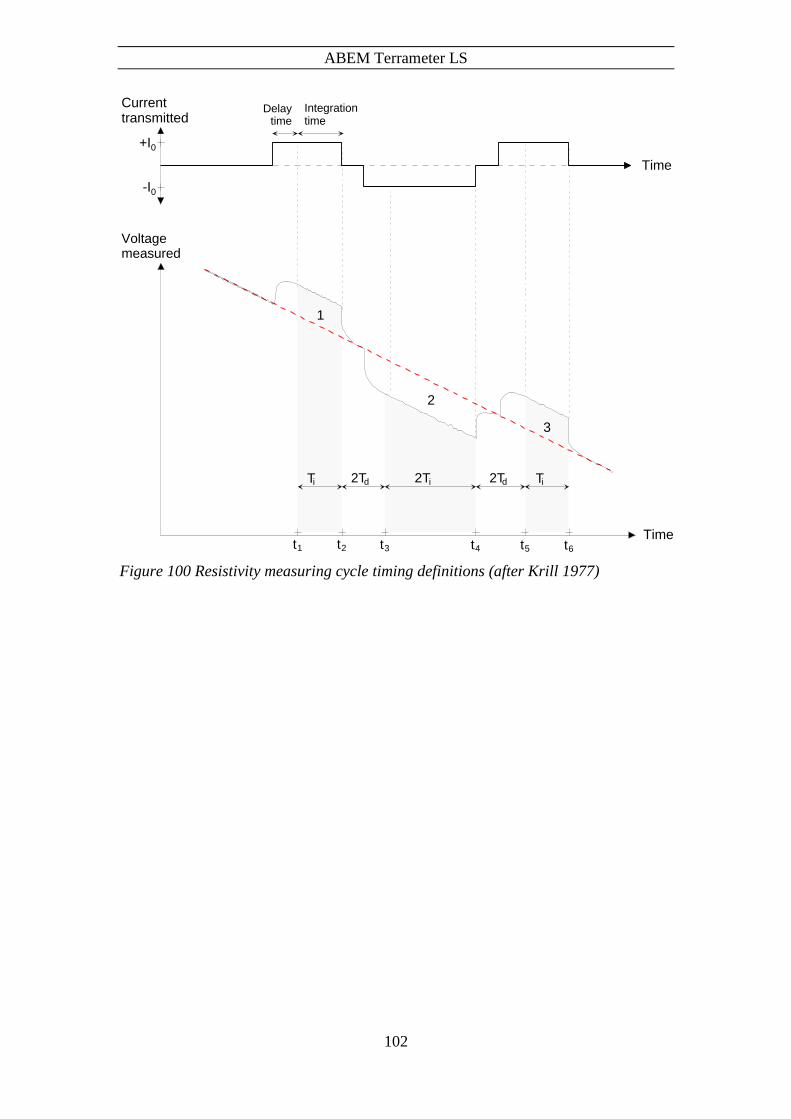
ABEM Terrameter LS
102
Figure 100 Resistivity measuring cycle timing definitions (after Krill 1977)
Current transmitted
+I0
-I0
Voltage measured
T i T i2Td 2Td2T i
Time
Time
1
2
3
t1 t2 t3 t4 t5 t6
Integrationtime
Delaytime
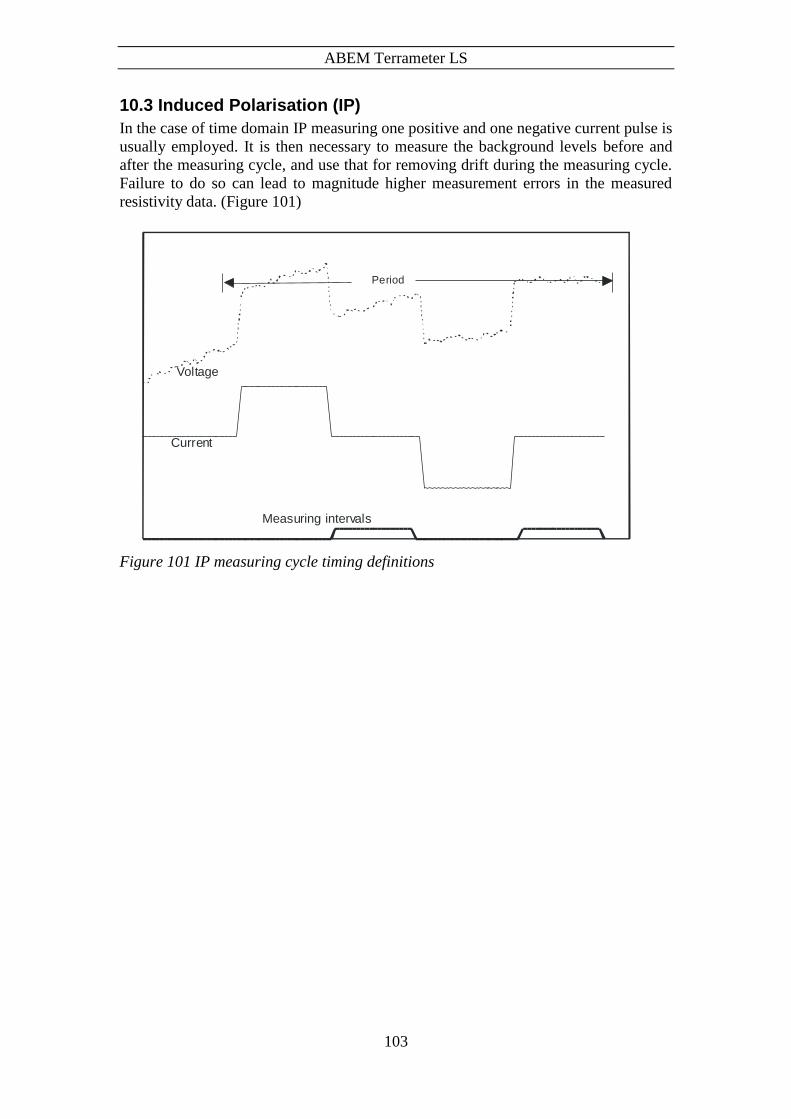
ABEM Terrameter LS
103
10.3 Induced Polarisation (IP)
In the case of time domain IP measuring one positive and one negative current pulse is
usually employed. It is then necessary to measure the background levels before and
after the measuring cycle, and use that for removing drift during the measuring cycle.
Failure to do so can lead to magnitude higher measurement errors in the measured
resistivity data. (Figure 101)
Figure 101 IP measuring cycle timing definitions
Period
Current
Voltage
Measuring intervals

ABEM Terrameter LS
104
11 Appendix C. Spread and Measuring Sequence Files
11.1 General
The measurement process is controlled via spread description files and protocol
(measuring sequence) files. A protocol file must always refer to a spread description
file, and a protocol file may in some cases be used in combination with different spread
description files. These files are in XML format and consequently have XML filename
extension. A list of supplied measuring sequence / protocol files can be found in
“Section 11.14 - Standard Measuring Sequence Files”.
The same protocol files can be used for instruments with different number of channels,
so that the same protocol can be used for an instrument with 4, 8 or 12 channels. It may,
however, be possible that protocol files using different strategies for optimising the use
of the channels are most suited for the different versions of the instrument.
For older versions of the ABEM Lund Imaging System the spread description files are
called address files (ADR filename extension). Separate files were used for the first
measurement station (.ORG) and following stations in the roll-along procedure (.UP
and .DWN), but that is not needed for Terrameter LS. Utility software that converts
from the old to the new system is available in the Terrameter LS Toolbox (“Protocols /
Convert ADR to XML Spread File” and “Protocols / Convert ORG to XML Protocol
File” respectively).
There are lots of programs available for editing XML files. A basic text editor such as
Notepad will do just fine, but using a dedicated XML editor is recommended. There
are a number of XML editors available on the market and one free alternative is XML
Marker. It can be downloaded from www.symbolclick.com
11.2 Spread Description Files in XML-format
The spread description files define the hardware configuration of the measurement;
including parameters such as number of electrode cables, number of electrode take-outs
per cable and roll-along direction and step size. It also contains the necessary details on
the wiring between electrode take-outs and the physical relay switch channels. A spread
description file can be as simple as specifying how the C1, C2, P1 and P2 terminals are
connected to the internal receiver and transmitter, or it can be more complex and include
for instance number of electrode cables, number electrode take-outs per section, internal
and external addresses of electrode channels, etc.
The files are self-explanatory since XML-format is used, but here are some brief
explanations:
<Cable> defines one electrode cable, and all electrodes belonging to the same cable
must be defined within the same <Cable> section.
<Id> is the electrode number that the protocol files refer to.
<X> refers to the position of the electrode along the spread in terms of number of
electrode spacing steps
<Name> is the text used to describe the electrode in for example the electrode
contact test.
<SwitchAddress> defines how the electrode is connected to the relay switch.
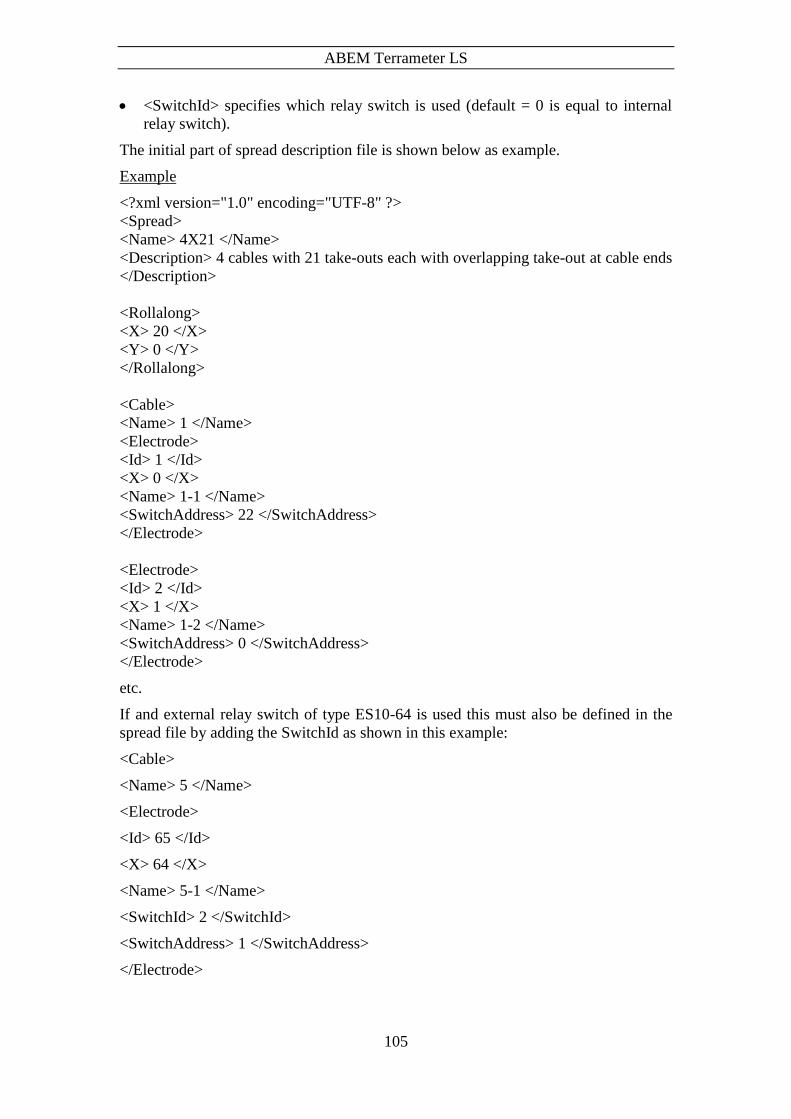
ABEM Terrameter LS
105
<SwitchId> specifies which relay switch is used (default = 0 is equal to internal
relay switch).
The initial part of spread description file is shown below as example.
Example
<?xml version="1.0" encoding="UTF-8" ?>
<Spread>
<Name> 4X21 </Name>
<Description> 4 cables with 21 take-outs each with overlapping take-out at cable ends
</Description>
<Rollalong>
<X> 20 </X>
<Y> 0 </Y>
</Rollalong>
<Cable>
<Name> 1 </Name>
<Electrode>
<Id> 1 </Id>
<X> 0 </X>
<Name> 1-1 </Name>
<SwitchAddress> 22 </SwitchAddress>
</Electrode>
<Electrode>
<Id> 2 </Id>
<X> 1 </X>
<Name> 1-2 </Name>
<SwitchAddress> 0 </SwitchAddress>
</Electrode>
etc.
If and external relay switch of type ES10-64 is used this must also be defined in the
spread file by adding the SwitchId as shown in this example:
<Cable>
<Name> 5 </Name>
<Electrode>
<Id> 65 </Id>
<X> 64 </X>
<Name> 5-1 </Name>
<SwitchId> 2 </SwitchId>
<SwitchAddress> 1 </SwitchAddress>
</Electrode>

ABEM Terrameter LS
106
This must be specified for each relay address that is not in the internal switch. It is
automatically taken care of for switch addresses above 64 if a spread description in
ADR-format is converted using the Terrameter LS Toolbox.
11.3 Protocol Files in XML-format
The protocol files describe which electrode arrays are used and the measuring sequence,
and can be designed to do measurements using arbitrary arrays. A protocol file always
refers to at least one spread description file, which simplifies the protocol files
immensely since each electrode is simply referred to by its number as defined within
the <Name> tag in the spread description file.
Explanations to the tags:
<SpreadFile> specifies the associated spread description file. There may be more
than one alternative spread file, in which case this statement is repeated.
<Sequence> marks start and end of the measuring sequence.
<Measure> defines a measurement or set of measurements using one current
electrode pair.
<Tx> specifies the current electrodes used for a measurement.
<Rx> specifies the potential electrodes used for a measurement; there can be an
unlimited number of potential electrode pairs for a current electrode pair.
<Focus> are the pseudo section focus points for the current and potential electrode
combination calculated for an electrode spacing equal to one, will be scaled
according to the actual electrode spacing.
Examples
A <Measure> section in the XML measuring sequence file can look like this example:
<Measure>
<Tx> 1 64 </Tx>
<Rx>
22 43
<Focus>
<X> 32.5 </X>
<Z> 10.92 </Z>
</Focus>
</Rx>
</Measure>
This example shows a normal Wenner array, for which it is not possible to utilise the
multi-channel measuring capability.
Multiple gradient array, on the other hand, is efficient for multi-channel measuring,
and a <Measure> section may look like the example below:
<Measure>
<Tx> 1 61 </Tx>
<Rx>
7 13
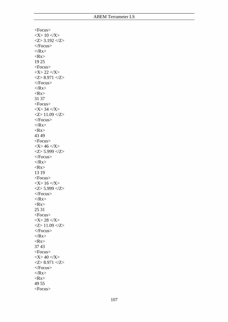
ABEM Terrameter LS
107
<Focus>
<X> 10 </X>
<Z> 3.192 </Z>
</Focus>
</Rx>
<Rx>
19 25
<Focus>
<X> 22 </X>
<Z> 8.971 </Z>
</Focus>
</Rx>
<Rx>
31 37
<Focus>
<X> 34 </X>
<Z> 11.09 </Z>
</Focus>
</Rx>
<Rx>
43 49
<Focus>
<X> 46 </X>
<Z> 5.999 </Z>
</Focus>
</Rx>
<Rx>
13 19
<Focus>
<X> 16 </X>
<Z> 5.999 </Z>
</Focus>
</Rx>
<Rx>
25 31
<Focus>
<X> 28 </X>
<Z> 11.09 </Z>
</Focus>
</Rx>
<Rx>
37 43
<Focus>
<X> 40 </X>
<Z> 8.971 </Z>
</Focus>
</Rx>
<Rx>
49 55
<Focus>

ABEM Terrameter LS
108
<X> 52 </X>
<Z> 3.192 </Z>
</Focus>
</Rx>
</Measure>
Note that the number of channels in an instrument does not restrict the number of
potential measurements for a current electrode pair, and that the same measurement
sequence file can be used for an instrument with 4, 8 or 12 channels4.
11.4 Spread Files for Pole-dipole
It is important that the spread file contains the remote electrodes that are in use.
Adding the example part of the spread file shown below can do this.
Example of a part of the spread file for pole-dipole:
<Cable>
<!-- Add remote electrodes -->
<Name> LS Panel </Name>
<Electrode>
<Id> 102 </Id>
<Name> C2 Current </Name>
<SwitchId> 0 </SwitchId>
<SwitchAddress> 2</SwitchAddress>
</Electrode>
</Cable>
11.5 Protocol Files for Pole-dipole
Example of the protocol file
<Measure>
<Tx> 23 0 </Tx>
<Rx>
22 21
<Focus>
<X> 22.25 </X>
<Z> 0.52 </Z>
</Focus>
</Rx>
</Measure>
The line "<Tx> 23 0 </Tx>" will tell the software to translate the reference to
electrode id 0 to the "C2 Current" electrode.
The software will look for the electrode with switchid=0 and switchaddress=2. The id
of the remote electrode (for instance102) must be unique within the spread and not 0.
4 Note: The overall efficiency in the use of the measuring channels may differ and it might be possible
to optimise the array combinations differently depending on the number of the measuring channels.

ABEM Terrameter LS
109
11.6 Spread Files for Pole-pole
Two remote electrodes must be specified in the spread file.
<Cable>
<!-- Add remote electrodes -->
<Name> LS Panel </Name>
<Electrode>
<Id> 102 </Id>
<Name> C2 Current </Name>
<SwitchId> 0 </SwitchId>
<SwitchAddress> 2</SwitchAddress>
</Electrode>
<Electrode>
<Id> 104 </Id>
<Name> P2 Potential </Name>
<SwitchId> 0 </SwitchId>
<SwitchAddress> 4</SwitchAddress>
</Electrode>
</Cable>
The id 102 and 104 for C2 and P2 can be selected arbitrary. In protocol itself, 0 can be
used as electrode number. In case of extension of the system with additional electrode
selectors (ES10-64) there will be real electrodes in with id 101, 102, 103, 104 etc., and
then other arbitrary id numbers such as for example 501, 502, 503, 504 can be used for
remote electrodes. Here it is only important to have a unique id for each electrode. The
software uses the switch id and switch address to find the remote electrode.
11.7 Protocol Files for Pole-pole
Example of protocol file
<Measure>
<Tx> 1 0 </Tx>
<Rx>
49 0
<Focus>
<X> 25 </X>
<Z> 41.66 </Z>
</Focus>
</Rx>
The line "<Tx> 1 0 </Tx>" will tell the software to translate the reference to electrode
id 0 to the "C2 Current" electrode, and <Rx> 49 0 will tell the software to translate the
reference to electrode id 0 to the "P2 Potential" electrode.
11.8 Optimising the Use of Channels for Pole-pole
While it is possible to make pole-pole measurements with the Terrameter LS without
any special accessories, using a special device can optimise the use of measuring
channels. The interconnections of all channels “P2” to the remote potential electrode

ABEM Terrameter LS
110
can be done via an adapter connected to the external connector AUX or the connector
Interconnect. The wiring of the adapter should connect the pins C, X, Z and b in the
KPT32 connector AUX5. This will interconnect every second row of the switch and the
remote potential electrode will be possible to route to all receiver channels. It is the
same wiring for 4, 8 or 12 channel systems. The signals are also available in the
Interconnect connector pin N, R, T and V in the KPT19 connector, so the wiring could
be done there as an alternative.
An additional option in the spread file sets the pole mode for the spread. It is only
needed if you connect an adapter that modifies the wiring of the instrument.
<PoleMode>
P2Half
</PoleMode>
This tells the software that a special hardware device is attached that will connect half
of the rows (4, 6, 8, 10) of the switch to the P2 remote electrode. It is only the external
part of the switch that will be affected.
Valid options are:
NoPol - No remote pole electrodes
P1, - P1 is in use. This is automatic if P1 is defined in spread
P2, - P2 is in use. This is automatic if P2 is defined in spread
P1P2, - P1 and P2 are in use. This is automatic if P1 and P2 is defined in spread
P1Half, Connect P1 to half of the rows in the switch 3, 5, 7, 9
P2Half, Connect P2 to half of the rows in the switch 4, 6, 8, 10
P1P2Half, Connect P1 to 3, 5, 7, 9 and Connect P2 to 4, 6, 8, 10
P1All, Connect P1 to row 3-10. (This will only shortcut the outside P1 and P2
connectors)
P2All, Connect P2 to row 3-10 (This will only shortcut the outside P1 and P2
connectors)
11.9 Protocol Files in XML-format for VES
Manual movement of electrodes can be used for measuring with geometries not
compatible with electrodes cables designed for standard 2D and 3D multi-electrode
surveying. Each movement of electrodes must then be done manually according to the
positions defined in the protocol file. One measurement point is defined by a set of
descriptions <Select> and <Move> tags:
<Select> MN/2= 0.2 AB/2= 1
<Move> 1 <X> 1 </X> </Move>
<Move> 2 <X> -1 </X> </Move>
<Move> 3 <X> 0.2 </X> </Move>
<Move> 4 <X> -0.2 </X> </Move>
</Select>
5 The cable intended for pole-pole measurement with SAS4000 and ES464 (part no. 33 0020 14) will do
the job if connected to AUX (the other end of the cable should not be connected).

ABEM Terrameter LS
111
The text immediately after the <Select> tag will be displayed on the instrument Screen,
and the <Move> tags define the electrode coordinates used for calculating the electrode
positions in the data file. The entire statement above can be written on one line if
preferred.
The electrodes are connected via cables to C1, C2, P1 and P2 connectors on the contact
panel. This is defined in the following statement:
<Sequence>
<Measure>
<Tx> 1 2 </Tx>
<Rx> 3 4 </Rx>
</Measure>
</Sequence>
11.10 Cable Description Files in ADR-format
The address files (cable description files - extension .ADR) are the equivalent of the
spread files in the system used by older versions of the ABEM Lund Imaging System.
It contains information about the physical configuration of the measuring channels in
relation to connections and cables presently used, and includes for instance number of
electrode cables, number electrode take-outs per section, internal and external addresses
of electrode channels, etc. All parameters are integers. Since one way of creating a
spread file for Terrameter LS is to convert from and ADR-file the format is given as
reference here.
The following format is used in the files:
nsec neach { number of electrode cables, total number of take-outs per cable }
nskip nx-move [ny-move] { active electrode skip factor, lengths for x-move, lengths for y-
move }
ntot [nx] { total no of active take-outs, no of take-outs in x-direction }
1 adr1 cable1-pos1 { number, internal address and physical position of 1st take-out }
2 adr2 cable2-pos2 { number, internal address and physical position of 2nd take-out }
...
...
ntot adrntot cablentot-posntot { number, internal address and physical position of last
take-out }
For line oriented cable arrangements with roll-along in the direction of the cable the
parameters ny-move and nx are not specified, but only for area cover and 3D cable
arrangements. In these cases the parameter nx-move is set to zero. Excluded electrode
positions can be entered into the address file by assigning the address 0 (zero). These
electrode positions will then be omitted from electrode contact test and measuring.
Example address files can be found in “Section 11.13 - Standard Spread Files”.
Note that the pins 22-32 in the standard cables with 21 take-outs each are not connected
to any electrode take-outs, but used for linking every second take-out on the outer
electrode cables to the Terrameter / Electrode Selector via the cable joints.

ABEM Terrameter LS
112
11.11 Protocol Files in ORG-format
The format of protocol files in the system used by older versions of the ABEM Lund
Imaging System is presented here for reference since one way of creating an XML-
format protocol file is to convert from this format. The first station (midpoint position)
is always measured using a protocol file with .ORG filename extension. Consecutive
stations use .UP or .DWN protocol files depending on if the roll-along is done towards
higher or lower coordinates. The .UP or .DWN files are reduced according to the
possible data overlap with the previous station, to avoid measuring the same data points
twice. This also means that measuring is normally much faster for consecutive stations
at a roll-along than for the first. Terrameter LS automatically reduces the measurements
at consecutive stations for overlap with measurements already taken at previous stations,
so it is only necessary to convert the ORG-file
If more than one protocol file is used for each station there is also a possible overlap,
between the protocol files at the same midpoint, as for example when doing Wenner
CVES with long and short layouts. In this case one of the files should be reduced
accordingly.
The protocol files contain an array code, the address file used followed by a comment
string, and the logical positions of the electrodes. The positions are given for the current
electrodes followed by the position of the potential electrodes. The format is thus:
code [arraystring]
addressfile [commentstring]
Apos(1) Bpos(1) Mpos(1) Npos(1)
Apos(2) Bpos(2) Mpos(2) Npos(2)
...
Apos(n) Bpos(n) Mpos(n) Npos(n)
where the electrode positions are given as integers in the interval 1-ntot. If remote
electrodes are used these positions are specified as zero.
The array codes are used mainly for presentation purposes, and in the case of pole-pole
and pole-dipole how the contact test is performed. The array codes used for Terrameter
LS are compatible with Res2dinv, and they differ from what is used by Terrameter
SAS1000 / SAS4000. The following codes are defined:
Electrode Array
Array Code
Code in Old System
Resistance 0 0
Wenner- 1 1
Pole-Pole 2 4
Dipole-dipole 3 5
Pole-dipole 6 6
Schlumberger 7 10
Equatorial dipole-dipole 8 13
General surface array 11 11
Tomography 12 12

ABEM Terrameter LS
113
Potential 14 14
Multiple gradient array 15 15
If an array not defined in the list is to be used, array code 11 for general surface array
may be used. Alternatively array code 0 for resistance can be used, which means that
resistance instead of apparent resistivity is displayed during measurement. If array code
12 is used only the electrode numbers, and not the coordinates are saved, which is
suitable for for instance measurements involving boreholes (see section on geometry
files below).
11.12 Geometry Files
The electrode coordinates for a borehole measurement are entered via a geometry file
(textfile with XYZ file extension), with the following format:
n-cables Header cable 1 1 x1,1 y1,1 z1,1 2 x1,2 y1,2 z1,2 … n1 x1,n1 y1,n1 z1,n1 Header cable 2 1 x2,1 y2,1 z2,1 2 x2,2 y2,2 z2,2 … n2 x2,n2 y2,n2 z2,n2 Header cable 3 1 x3,1 y3,1 z3,1 2 x3,2 y3,2 z3,2 … n3 x3,n3 y3,n3 z3,n3
11.13 Standard Spread Files
A number of standard spread files are supplied with Terrameter LS. It should be noted
that new files can be added and that the list may thus not be complete. The following
spreads are included with a standard firmware installation.
Name Description
2x21 Set of 2 electrode cables with 21 take-outs each
2x32 increasing Set of 2 electrode cables with 32 take-outs each
2x32 mirrored Set of 2 electrode cables with 32 take-outs each
4x21 Set of 4 electrode cables with 21 take-outs each
4x16 Set of 4 electrode cables with 16 take-outs each
11.14 Standard Measuring Sequence Files
A number of standard measuring sequence (protocol) files are supplied with all
Terrameter LS spread files, as listed below. It should be noted that new files can be
added without notice and that this list may thus not be complete.

ABEM Terrameter LS
114
Name
Gradient
Dipole-Dipole
Pole-Dipole
Pole-Pole
Schlumberger
Wenner
11.15 Standard Test and Diagnostic Protocols
A number of standard test and diagnostic protocols are supplied with Terrameter
LS.The following files are included:
Spread Protocol
LS internal Selftest, Calibrated 2,5 V, Calibrate 15V
C1C2P1P2 Simple RES
MCA Conn 1-32 Simple RES MCA
MCA Conn 33-64 Simple RES MCA