user handbook color instrument model fi-70
TRANSCRIPT

www.furuno.com
COLOR INSTRUMENT Model FI-70USER HANDBOOK
This User Handbook covers the basic installation and operation of the FI-70. For detailed information, refer to the Operators Manual, accessible from the URL or quick response code to the right. URL: http://www.furuno.com/en/support/manuals/termsIn the search box at the top of the screen, enter “FI-70”, then click “Search”.
SAFETY INSTRUCTIONS............................................................................................................ 1UNIT OVERVIEW, FUNCTIONS.................................................................................................. 2INSTALLATION ............................................................................................................................ 2
Flushmount Installation ........................................................................................................ 2Frontmount Installation (Option)........................................................................................... 3
WIRING ........................................................................................................................................ 4Network Connection............................................................................................................. 4Grounding ............................................................................................................................ 4
INITIAL SETTINGS....................................................................................................................... 5How to Select a Language and Units of Measurement........................................................ 5How to Set Up Own Ship Type ............................................................................................ 5How to Select the Data Source ............................................................................................ 6How to Set Up the IF-NMEAFI (option) ................................................................................ 6
STANDARD OPERATION............................................................................................................ 7How to Adjust Brilliance and Change Between Day/Night Modes ....................................... 7How to Change Pages ......................................................................................................... 7How to Adjust Page Settings (Displayed Category) ............................................................. 7Page List by Category.......................................................................................................... 8
HOW TO EDIT THE CUSTOM BOXES........................................................................................ 9How to Adjust Data Box Displayed Data.............................................................................. 9How to Adjust Data Box Size Settings ............................................................................... 10
SHARING AND GROUPS .......................................................................................................... 11Network Settings ................................................................................................................ 11Language and Brilliance Sharing Between FI-70 Units...................................................... 11
MENU TREE............................................................................................................................... 12Main Menu ......................................................................................................................... 12Category Specific Menus ................................................................................................... 14
OUTLINE DRAWINGS .........................................................................................................D-1INTERCONNECTION DIAGRAM........................................................................................ S-1
TABLE OF CONTENTS
All brand and product names are trademarks, registered trademarks or service marks of their respective holders.

Observe the following compass safedistances to prevent interference to amagnetic compass:
StandardCompass
SteeringCompass
Mandatory ActionProhibitive Action
WARNING Indicates a potentially hazardous situation which, if not avoided, could result in death or serious injury.
CAUTION Indicates a potentially hazardous situation which, if not avoided, can result in minor or moderate injury.
Warning, Caution
The operator and installer must read the applicable safety instructions before attempting toinstall or operate the equipment.
FI-70 0.30 m 0.30 m
WARNINGDo not open the equipment.
Only qualified personnel should work inside the equipment. There areno servicable or replacable parts inside the equipment.
Do not disassemble or modifythe equipment.
Fire or electrical shock can result ifthe equipment is modified.
Do not operate the equipmentwith wet hands.
Electrical shock can result.
Safety instructions for the operator
Make sure no rain or water splash leaks into the equipment.
Fire or electrical shock can resultif water leaks into the equipment.
Immediately turn off the powerat the switchboard if water leaksinto the equipment.
Continued use of the equipment can cause fire or electrical shock.
Safety instructions for the installer
WARNING
CAUTION
Turn off the power at the switch-board before beginning theinstallation.
Turn off the power to preventelectrical shock.
Make sure the installation site isnot subject to water spray.
Fire or electrical shock can result ifwater leaks into the equipment.
About the TFT LCD
The TFT LCD is constructed using the latest LCD techniques, and displays 99.99% of its pixels. The remaining 0.01% of the pixels
may drop out or blink, however this is not an indication of malfunction.
SAFETY INSTRUCTIONS
1

1. Power/Brill key1. Power/Brill key
2. Menu/Back key2. Menu/Back key
3. Software keys3. Software keys
4. Function key4. Function key
5. Key Indicators5. Key Indicators
11
2233
44455
FI-50 RetrofittingFI-50 RetrofittingFI-50 RetrofittingFI-50 RetrofittingFI-50 Retrofitting
Key indicators and corresponding keysKey indicators and corresponding keysKey indicators and corresponding keysKey indicators and corresponding keysKey indicators and corresponding keys
Func NextPrev
UNIT OVERVIEW, FUNCTIONS
INSTALLATION
Turn power on/off Open Brilliance window
Change displayed page
Confirm selection/changes Switch displayed data
Adjust settingsMove cursor
Open/close the menu Go back one menu layer
The indicators show the operative function for the Software and Function keys. Press any key to display the indicators. If there is no operation, the indicators are minimized after a short period of time, however, they are always displayed when a menu is open. The indications vary, depending on the displayed screen/menu.
Installation considerationsWhen installing the FI-70, keep the following points in consideration:
Select a well-ventilated location.Select a location with minimal vibrations and shock.Keep the FI-70 away from heat sources.Observe the compass safe distances.(Standard: 0.30 m, Steering: 0.30 m)Select a location with a smooth surface.(1 mm flatness or less)Keep cable lengths in mind when selecting the mounting location.
When not in use, fit the rubber cover to the FI-70.Leave sufficient room surrounding the FI-70 to allow fitting of the rubber cover.Referring to the outline drawings at the back of the handbook, leave sufficient space for service and maintenance.Where the rear connector or T-connectors may get wet, waterproof the connectors. (See page 4 for how to waterproof the connectors.)
Flushmount InstallationUsing the supplied template, mark and cut a hole in the installation location.Fit the supplied stud bolts (M3×40, 2 pcs) to the rear of the FI-70.Note: Do not use tools to fit or insert the stud bolts.Fit the supplied flushmount sponge to the rear of the FI-70.
Set the FI-70 into the mounting hole.Fit and tighten the washers and butterfly nut.
12
3
5Referring to page 4, connect and ground the FI-70.4
6
Spring washerButterflynutFlat washer
Console
Flushmount sponge
Stud bolt
When retrofitting from the FI-50 series unit to the FI-70, drill new bolt holes to fit the stud bolts for the FI-70. The FI-70 can then be installed in place of the FI-50 series unit.
Using locally supplied materialsUsing locally supplied materialsUsing locally supplied materialsUsing locally supplied materialsUsing locally supplied materialsWhen using locally supplied screws to secure the FI-70, the thread depth should be approx. 5 mm, as indicated in the figure to the right.
Approx. 5 mm
2

Frontmount Installation (Option)The optional frontmount kit OP26-29 may be used to install the FI-70 where access behind the console is limited.
Using the template supplied with the frontmount kit, cut a hole in the mounting location.Fit the snap pins (supplied) to the FI-70, as shown in the figure below.Fit the frontmount panel to the console with four self-tapping screws (supplied).Referring to page 4, connect and ground the FI-70.Set the FI-70 into the frontmount panel, using the snap pins and snap pin slots as guides.Push the FI-70 into the frontmount panel until a “click” sound is made, indicating that the FI-70 is now secure in the panel.
Snap pinSelf-tapping screw
Frontmount panel
Console
Console rearConsole rear
Snap pinSnap pinPin holders
Release the pin holderRelease the pin holder
To remove the FI-70 from the frontmount panel, release the pin holders at the back of the panel, then remove the FI-70. Failure to release the pin holders when removing the FI-70 may damage the FI-70, the pin holders or the pins.
Removing the FI-70 from the frontmount panelRemoving the FI-70 from the frontmount panel
Preventing water seepage from the mounting holesPreventing water seepage from the mounting holes
123456
Note: Do not fit the flushmount sponge to the FI-70. The unit will not lock into the frontmount panel.
Indicates locking points for soft cover
Where there is a risk of water seepage behind the unit or through the screw holes, apply marine sealant around the FI-70 for waterproofing. Referring to the figure on the right, apply masking tape to the soft cover locking points to prevent marine sealant from blocking the locking points.There are eight locking points in total, four at the top rear of the unit and four at the bottom rear of the unit.Marine sealant blocking these locking points will prevent the soft cover from fitting to the FI-70.
Washers
3

WIRING
Network ConnectionNetwork Connection GroundingGrounding
FI-50 Series RetrofittingFI-50 Series RetrofittingFI-50 Series RetrofittingFI-50 Series RetrofittingFI-50 Series Retrofitting
Use the included cable to connect the FI-70 NMEA2000 port to the CAN bus (NMEA2000) network backbone.
Fabricate a ground wire (IV-1.25sq., local supply) with a closed-end terminal.Unfasten the ground terminal screw, then referring to the figure below, connect the ground wire to the ground terminal of the FI-70.Connect the loose end of the ground wire to the ship’s ground terminal.
1
2
3
1
2
3
NMEA2000 port
Ground terminal
Console rear
NMEA Cable assy.(M12-05BM+05BF-060, 6 m)
To CAN bus (NMEA2000) backbone
Flat washer*
Ship’s ground terminal
Ground wire(IV-1.25sq., local supply)
Terminal screw*
Unlike the FI-50 series, the FI-70 cannot be daisy-chained. When retrofitting from a FI-50 series unit, create a new CAN bus (NMEA2000) network connection.
How to waterproof the connectorsHow to waterproof the connectorsHow to waterproof the connectorsHow to waterproof the connectorsHow to waterproof the connectorsWhere the rear connectors and CAN bus (NMEA2000) connectors are subjected to moisture or water spray, waterproof the connectors as shown below.
Analog sensors
Tank gauge Speed/Temp. SensorST-02MSB/ST-02PSB
Wind Transducer FI-5001/L
Color Instrument FI-70 (Maximum 11 units)
CAN bus (NMEA2000) Backbone: Terminal resistors must be installed at both ends of the backbone.
Analog NMEA Data ConverterIF-NMEAFI
CAN bus (NMEA2000)
sensors
CAN bus (NMEA2000)
sensors
*: Attached to FI-70 when shipped. Remove the terminal screw and washer to install.
Junction BoxFI-5002
Junction BoxFI-5002
Waterproof the connectors
T-connector
Wrap the connection point with a single layer of vinyl tape.Wrap one layer of self-bonding tape over the vinyl tape.Wrap two layers of vinyl tape over the self-bonding tape.
12 VDCto
15 VDC
4
INITIAL SETTINGS
How to Select a Language and Units of MeasurementHow to Select a Language and Units of Measurement
Initialization
Language
Units
Type:
Engine Setup
Francais
Espanol
Deutsch
Initialization
Language
Units
Type:
Engine Setup
English
How to Set Up Own Ship TypeHow to Set Up Own Ship Type
English
Ent Ent
Initialization
Language
Units
Type:
Engine Num
English
Ent
Power Boat
Initialization
Language
Units
Type:
Engine Setup
English
Ent
Sailboat
Engine Monitor
Power Boat
Page1
2
3
4
56
7
Power Boat Sailboat Engine MonitorCompass Compass
STW
Water Temp. Graph STW
Custom Box (POSN, STW, COG) Custom Box (STW)
Custom Box (POSN, W Temp., SOG)
AWA
Custom Box (POSN, AWS, STW)
Engine
Data Box (Engine Oil, Engine Temp., etc.)
OFF
OFFOFF
OFF
OFF
OFF
OFF
OFF
OFF
Vessel-type default display settingsVessel-type default display settings
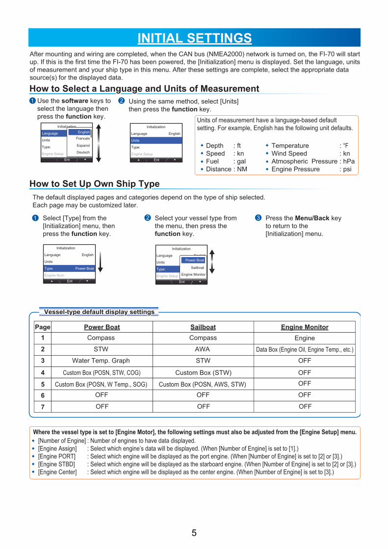
After mounting and wiring are completed, when the CAN bus (NMEA2000) network is turned on, the FI-70 will start up. If this is the first time the FI-70 has been powered, the [Initialization] menu is displayed. Set the language, units of measurement and your ship type in this menu. After these settings are complete, select the appropriate data source(s) for the displayed data.
Use the software keys to select the language then press the function key.
1 2 Using the same method, select [Units] then press the function key.
Units of measurement have a language-based default setting. For example, English has the following unit defaults.
DepthSpeedFuelDistance
: ft: kn: gal: NM
TemperatureWind SpeedAtmospheric PressureEngine Pressure
: °F: kn: hPa: psi
The default displayed pages and categories depend on the type of ship selected.Each page may be customized later.
Select [Type] from the [Initialization] menu, then press the function key.
Select your vessel type from the menu, then press the function key.
Press the Menu/Back key to return to the [Initialization] menu.
1 2 3
Where the vessel type is set to [Engine Motor], the following settings must also be adjusted from the [Engine Setup] menu. [Number of Engine][Engine Assign][Engine PORT][Engine STBD][Engine Center]
: Number of engines to have data displayed.: Select which engine’s data will be displayed. (When [Number of Engine] is set to [1].): Select which engine will be displayed as the port engine. (When [Number of Engine] is set to [2] or [3].): Select which engine will be displayed as the starboard engine. (When [Number of Engine] is set to [2] or [3].): Select which engine will be displayed as the center engine. (When [Number of Engine] is set to [3].)
5

Ent
Sensor in Use
System
Alarm Log
System
I/O Setup
Data Source
Data Calibration
Demo Mode:Ent
OFF
Data Source
Position:
Heading:
STW:
SOG:
----------------
Ent
----------------
----------------
----------------
Data Source
Position:
Heading:
STW:
SOG:
----------------
Ent
----------------
----------------
----------------
---------------
SC-30 :000200
How to Select the Data SourceHow to Select the Data Source
How to Set Up the IF-NMEAFI (option)How to Set Up the IF-NMEAFI (option)
System
Display Format
Engine Setup
Scale Range
IF-NMEAFIEnt
IF-NMEAFI
Select IF:
Category:
Resistance Full:
Resistance Mid:
----------------
Ent
0hm
0h,
WS-200 :000032
Automatic data source switchingAutomatic data source switchingAutomatic data source switchingAutomatic data source switchingAutomatic data source switching
Ent
Sensor in Use
System
Alarm Log
IF-NMEAFI
Select IF:
Category:
Resistance Full:
Resistance Mid:
----------------
Ent
0hm
0h,
---------------
IF-NMEAF :000007
IF-NMEAFI
Select IF:
Category:
Resistance Full:
Resistance Mid:
IF-NMEAF: 000007
Ent
0hm
0h,
Wind
IF-NMEAFI
Select IF:
Category:
Resistance Full:
Resistance Mid:
----------------
Ent
0hm
0h,
Wind
Wind
ST800/ST850
IF-NMEAF :000008 Fuel
Flesh Water
IF Categories and their respective sensors/gaugesIF Categories and their respective sensors/gaugesIF Categories and their respective sensors/gaugesIF Categories and their respective sensors/gaugesIF Categories and their respective sensors/gauges
This section explains how to set the data source(s) for displayed data.Select [System] from the main menu, then press the function key.
Select [Data Source], then press the function key.
Select the item who’s data source you wish to adjust, then press the function key.
1 2
Select [System] from the main menu, then press the function key.
Select [IF-NMEAFI], then press the function key.
1 2 Select [Select IF], then press the function key.
2
3
3
Select the device to use as the data source, then press the function key.
Repeat steps 3 to 4 to set up the remaining data sources.
4
Select the IF-NMEAFI to set up, then press the function key.
Select the [Category], then press the function key.
4
5
5 6
If data from any data source is interrupted, the FI-70 will automatically switch data sources to the next available source. If there is no source available, the data is not displayed.
When connecting analog sensors such as the wind transducer FI-5001/L, the optional IF-NMEAFI data converter must be used as between the sensor and the FI-70. When using the IF-NMEAFI, set up the IF-NMEAFI using the following procedure.
Select the connected sensor’s category, then press the function key.
[Wind]: FI-5001/L wind sensor[Fuel]: Fuel tank gauge[Waste Water]: Waste tank gauge[Oil]: Oil tank gauge
[ST800/ST850]: Water temperature sensor (ST-02PSB/MSB)[Fresh Water]: Fresh water tank gauge[Live Well]: Live well tank gauge[Black Water]: Black water tank gauge
6

STANDARD OPERATIONHow to Adjust Brilliance and Change between Day/Night ModesHow to Adjust Brilliance and Change between Day/Night Modes
Screen brilliance settings sharingScreen brilliance settings sharingScreen brilliance settings sharingScreen brilliance settings sharingScreen brilliance settings sharing
Screen brilliance auto reductionScreen brilliance auto reduction
How to Change PagesHow to Change Pages
Each page may be customized to suit your needs.
How to Adjust Page Settings (Displayed Category)How to Adjust Page Settings (Displayed Category)
Ent
System
Wind Angle
Alarms
Wind Speed
Disp Config
Ent
50ºAWA
T
NextPrev
Select a page to setup.Select screen category.
CompassEnt
Ent
Select screen.
CompassEnt NextPrev
Select a page to setup.
Categories and displayable screensCategories and displayable screensCategories and displayable screensCategories and displayable screensCategories and displayable screens
Screen brilliance and changing from Day to Night mode may be done from the Brilliance setting window. The Brilliance setting window disappears if the Menu/Back is pressed, or if there is no interaction over a short period.
Press the Power/Brill key to display the Brilliance setting window.
Press the software keys to select the desired brilliance.*
Press the function key to change between Day and Night modes.
1 2 3
*: The brilliance may also be changed by pressing the Power/Brill key. Day mode Night mode
FI-70 units on the same network may be grouped, allowing the brilliance settings and language settings to be shared. For example, if one FI-70 in Group A has the brilliance setting adjusted, all FI-70 units in Group A are also adjusted. For further details on groups, see page 11.
Press the Menu/Back key to display the menu. Select [Disp Config], then press the function key.
Select the screen type (where available) then press the function key.
Press the Menu/Back key to complete the process.
Select the page you wish to customize, then press the function key.
Select the Category you wish to display, then press the function key.
Example: Compass category is selected.
Some categories have only one displayable screen. For further details on displayable screens for each category and displayable data, see “Page List by Category” on page 8.
1
4
2
34º37.145'N5'N75º29.108'E8'E3855
42.2.2kn
º5050
5
3
When the FI-70 is subjected to undue heat, the brilliance may be automatically lowered. This is designed to prevent over-heating and is not a malfunction.
Func NextPrev
POSN
35º32.548'N74º07.452'W
AWS STW45.9kn 10.9kn
Edit NextPrevFunc
50ºAWA
T
NextPrev Edit NextPrev
77Func NextPrev
11Func NextPrev
22 33 44 55Depth
POSN 34º37.145’N34º37.145’N75º29.108’W75º29.108’W
38553855COG MSOG
42.542.5
W Temp.
345345
kn
ºF
Ent
ft
345345º66
Func NextPrev
POSN
35º32.548'N74º07.452'W
AWS STW45.9kn 10.9kn
Edit NextPrev
77Func NextPrev
11 33Func
50ºAWA
T
NextPrev
44Edit NextPrev
55
Press the software keys to change pages. A total of seven pages may be displayed.The page number is displayed in the center of the screen for several seconds.
Pages set to [OFF] are skipped when changing pages. In the example below, pages 2 and 6 are set to [OFF] and are skipped, the displayed pages would be [1 ↔ 3 ↔ 4 ↔ 5 ↔ 7].
Page 2 set to [OFF]
Page 6 set to [OFF]
7

CompassCompass SpeedSpeedCompass : Heading dataCompass : Heading dataCompass : Heading dataCompass : Heading dataCompass : Heading data STW : Speed Through WaterSTW : Speed Through WaterSTW : Speed Through WaterSTW : Speed Through WaterSTW : Speed Through Water SOG : Speed Over GroundSOG : Speed Over GroundSOG : Speed Over GroundSOG : Speed Over GroundSOG : Speed Over Ground
HDG
T
kn
0
5
10 15
20
17.8STW
STW
kn
0
5
10 15
20
17.8SOG
SOG
WindWindWind AngleWind Angle Ch Wind : Close Hauled WindCh Wind : Close Hauled Wind Ground WindGround Wind
50ºAWA
A
Wind Angle Ground Wind*1
Data display:
Page List by CategoryPage List by Category
AWA
T
27ºAWA
A
27ºAWA
A
EngineEngineEngine : Single engine displayEngine : Single engine display Engine : Dual engine displayEngine : Dual engine display Engine : Triple engine displayEngine : Triple engine display
x1000
RPM
3280Eng. Temp.
125.6
1
2 3
4
Eng. Temp. ºF
x1000 x1000
2600 3320
125.6 125.6
RPM
Eng. Temp. ºF
RPM
145025003500
125.6 125.6 125.6
x1000
12
3 4
12
3 4
12
3 4
12 3
4 12 3
4
RudderRudder GraphGraphRudderRudder 1Graph1Graph 2Graphs2Graphs
Rudder
P30º
DepthDepth
45004500
44004400
43004300
1010202030min30min
ftft43034303
On-screen data display may be changed by pressing the function key.Note1: On-screen data display requires connection of the appropriate sensor and [Data Source] menu set up.Note2: All maximum and average data are cleared at power off and calculated from power on.
1
1
1
1
1
13
3
3
1
3 3
3
32
2
2
2
2
Engine RPM Gear selection (N=Neutral, F=Forward, R=Reverse)Data display:
13
2
32 2 2
2Heading markerData display:HDG : HeadingHDG Avg. : Average headingHDG Tack : Heading after tack
Speed Through Water Speed Over GroundData display:STW : Speed Through Water STW Max : Maximum STW STW Avg. : Average STW SOG : Speed Over Ground SOG Max : Maximum SOG SOG Avg. : Average SOGVMG : Velocity Made Good (Only on STW screen)
1
1
1
1
13 3
1
1 1
1
Where [Wind Display] is set to [True]*2
TWA : True Wind Angle TWS Max : Maximum TWS Beaufort : TWS in Beaufort unitsWhere [Wind Display] is set to [Apparent]AWA : Apparent Wind Angle AWS : Apparent Wind Speed Beaufort : TWS in Beaufort units
Eng. Temp. (Engine temperature) Fuel Used Fuel Rate Eng. Hour (Engine hours) Oil Press (Oil Pressure) Oil Temp. (Oil temperature)Coolant P (Coolant Pressure) E Load (Engine Load) Gear Oil T (Gear oil temperature)Gear Oil P (Gear oil pressure) Boost
Rudder angle Select one or two items, depending on graph size, to be displayed from the following data:Depth W Temp (Water temperature)A Temp (Atmospheric temperature) A Press (Atmospheric pressure)
Note: Data shown in the engine category is input from engine sensors. Always check any malfunction at the engine, do not rely solely on the FI-70 indications.
44004400
10001000
990990
43004300DepthDepth
ftft42564256
A Press.A Press.
hPahPa10031003
1010202030min30min
30min30min 10102020
*1: AWA, AWS, ship speed and heading data are required to display ground wind.*2: AWA, AWS and ship speed data are required to display true wind.
8

Time
Trip
00:00:00:00
0
15:00NM
Time
Trip
00:00:00:00
0
00:00NM
Time
00:00:00
15:00Lap
00:Lap Lap
TimerTimerCountdown Timer1Countdown Timer1Countdown Timer1Countdown Timer1Countdown Timer1
AISAIS
Countdown Timer2Countdown Timer2 Countup TimerCountup Timer
Countdown Timer Lap Time Trip Meter Countup Timer
NM
NN UP WAYPOINT
XTE
NM0.05P
HighwayHighway Custom BoxCustom Box
Depth
POSN 34º37.145’N34º37.145’N75º29.108’W75º29.108’W
38553855COG M
345345SOG
42.542.5 º
W Temp.
345345
kn
ºFft
How to Adjust Data Box Displayed DataHow to Adjust Data Box Displayed Data
Depth
POSN 34º37.145’N34º37.145’N75º29.108’W75º29.108’W
38553855COG MSOG
42.542.5
W Temp.
345345
kn
ºF
Ent
ft
Depth
POSN 34º37.145’N34º37.145’N75º29.108’W75º29.108’W
38553855COG MSOG
42.542.5
W Temp.
345345
kn
ºF
Ent
ft
Depth
POSN 34º37.145’N34º37.145’N75º29.108’W75º29.108’W
38553855COG MSOG
42.542.5
W Temp.
345345
kn
ºF
Ent
ft
Depth
POSN 34º37.145’N34º37.145’N75º29.108’W75º29.108’W
38553855COG MSOG
42.542.5
W Temp.
345345
kn
ºF
Ent
ft
Wind
Speed
Heading
Course
Depth
POSN 34º37.145’N34º37.145’N75º29.108’W75º29.108’W
38553855COG MHDG Avg. T
W Temp.
345345 ºF
Ent
ft
4545º
345345º 345345 345345ººSelect Box Size
Select Data
345345º 345345º
Prev Next
3
3
2
1
2
3
1
2
2
5
3
3
6
1
1
4
2
2
1
1
32
4
4
The simplified AIS category shows your and other vessel’s data as symbols. Up to 25 symbols, in order from closest to farthest, can be displayed.Note: The AIS category is a simplified AIS, with limited function and capacity. Only Class A and Class B AIS targets are displayed. Do not rely solely on the FI-70indications.
Waypoint name/markOwn ship symbolData display:XTE (Cross-track Error)WPT (Waypoint co-ordinates)RNG (Range to waypoint)BRG (Bearing to waypoint)
The Custom Box category can display up to six data boxes, each showing data input from sensors and other external sources. The boxes are fully customizable.
With the Custom Data box page displayed, press the function key.
Select the category to be displayed, then press the function key.
Select the box to adjust, then press the function key.
Press the software keys to select which data to display, then press the function key.
Press the Menu/Back key to complete the customization.
Select [Select Data], then press the function key.
HOW TO EDIT THE CUSTOM BOXES
9

Speed STW STW Max* STW Avg.*
SOG SOG Max* SOG Avg.*
VWG
Wind AWS TWS TWS Max*
AWA TWA
Beaufort
GWD M(T)
Heading HDG M(T) Average HDG M(T)*
HDG Tack M(T)
ROT
Course COG M(T)
Navigation BRG M(T) RNG WPT
XTE POSN ETA Time
ETA Date Trip Odometer
Boat Rudder Trim Tabs Roll/Pitch
Engine Engine RPM Fuel Used Fuel Rate
Eng. Trim Boost Eng. Temp.
Eng. Hour Oil Press. Oil Temp.
Coolant P E Load Gear Oil TGear Oil P
Tank T1 thru T6 tank information
Depth DepthEnvironment Date Time W Temp.
A Temp. A Press. Humidity
Wind Chill Dew Point
Voltage Volts
Disable display for this box.OFF
How to Adjust Custom Box Size SettingsHow to Adjust Custom Box Size Settings
Depth
POSN 34º37.145’N34º37.145’N75º29.108’W75º29.108’W
38553855COG M
345345SOG
42.542.5 º
W Temp.
345345
kn
ºF
Ent
ftSelect Data
Select Box Size
Depth
POSN 34º37.145’N34º37.145’N75º29.108’W75º29.108’W
38553855W Temp.
345345 ºF
Ent
ft
SOG
42.542.5 kn
NoteNoteNoteNoteNote
Depth
POSN 34º37.145’N34º37.145’N75º29.108’W75º29.108’W
38553855COG MSOG
42.542.5
W Temp.
345345
kn
ºF
Ent
ft
Depth
POSN 34º37.145’N34º37.145’N75º29.108’W75º29.108’W
38553855COG MSOG
42.542.5
W Temp.
345345
kn
ºF
Ent
ft
345345º 345345º
Prev Next
2 31 With the Custom Data box page displayed, press the function key.
Select the box to adjust, then press the function key.
Select [Select Box Size], then press function key.
4 5Press the software keys to select a box size, then press the function key.
Press the Menu/Back key to complete the customization.
Depending on the selected data type, some boxes have a fixed size and cannot be resized.
Displayable data for the data boxesNote: Sensor connection and data source settings are required for all listed data to be output.
Data Type Displayable data
*: The average and maximum values are calculated from when the FI-70 is turned on. All calculations for average and maximum are reset when the power is turned off.
10

SHARING AND GROUPSNetwork SettingsNetwork Settings
Rudder
P30º
Ent
System
System
Key Beep:
Panel Dimmer:
Sharing:
GroupEnt
OFF
8
Slave
A
System
Key Beep:
Panel Dimmer:
Sharing:
GroupEnt
OFF
8
Slave
A
Slave
Master
Stand Alone
CAN bus (NMEA2000) Network Shared Settings
Language and Brilliance Sharing Between FI-70 UnitsLanguage and Brilliance Sharing Between FI-70 Units
System
Key Beep:
Panel Dimmer:
Sharing:
GroupEnt
OFF
8
Slave
A
Enter Enter Enter EnterEnterEnter Enter Enter Enter Enter EnterEnterEnter EnterE EnterE
System
Key Beep:
Panel Dimmer:
Sharing:
GroupEnt
OFF
8
Slave
A
B
C
A
Rudder
P30º
Ent
System
Some settings and offsets for the FI-70 may be shared across a CAN bus (NMEA2000) network. See the list below for details.
2 31 Select [System] from the main menu, then press the function key.
Select [Sharing], then press the function key.
Select the sharing level for this FI-70 unit, then press the function key.
2 31 Select [System] from the main menu, then press the function key.
Select [Group], then press the function key.
Select the group for this FI-70 unit, then press the function key.
[Stand Alone]: Settings are not shared across the network. This unit can be set up individually.[Slave]: Settings are received from a Multi Function Display (TZTL12F/TZTL15F), or a FI-70 unit assigned as [Master].[Master]: Settings for this FI-70 are shared across the network. This option is not available if there is a Multi Function Display (TZTL12F/TZTL15F) in the same network. In this case, the TZTL12F/TZTL15F is made the [Master].
After setting the sharing levels for the network, settings between units can be shared.All shared settings are displayed as gray menu items on FI-70 units assigned as [Slave]. The shared settings cannot be adjusted from a [Slave] FI-70 unit.
[Display Format] menu [HDG/COG Ref], [Mag. Var.], [Time Offset] only
[Data Source] menu All menu settings, excluding tank information ([Tank1] through [Tank 6]).
FI-70 units may be grouped together in one or more groups, allowing language and brilliance settings to be shared between FI-70 units in the same group.As shown in the example figure below, adjusting the brilliance settings for one FI-70 unit in Group A changes the brilliance settings for all FI-70 units in the same group. While one FI-70 unit in a group has the brilliance adjusted or the language changed, all other FI-70 units in the same group cannot have the brilliance or language settings adjusted.
Group A Group B Group A Group B
Grouping the FI-70 units eliminates the need to adjust each unit indiviually. Up to three groups (A, B, C) may be set up.
[Data Calibration] menu All menu settings, excluding [W Angle Response].[Units] menu All menu settings.
11

MENU TREEMain MenuMain MenuMain Menu
Displayed page-based menus (See Pages 14 to 15)
Alarms
Disp ConfigAlarm LogSensor in UseSystem
STW Alarm
SOG Alarm
Max TWS Alarm
Wind Shift Alarm
High AWA Alarm
Low AWA Alarm
Trip Alarm
Depth Alarm
Voltage Alarm
W Temp. Alarm
Engine Alarm
Anchor Alarm
CPA/TCPA Alarm
Alarm (OFF, Low, High; 0.0kn to 999.9kn, 10.0kn)Buzzer (Short, Middle, Long, Continue)
Alarm (OFF, Low, High; 0.0kn to 999.9kn, 10.0kn)Buzzer (Short, Middle, Long, Continue)Alarm (OFF, ON; 0.0kn to 99.9kn, 19.4kn)Buzzer (Short, Middle, Long, Continue)Alarm (OFF, ON)Buzzer (Short, Middle, Long, Continue)
Alarm (OFF, ON)Buzzer (Short, Middle, Long, Continue)
Alarm (OFF, ON)CPA (0NM to 6.00NM, 0.00NM)TCPA (30sec, 1min, 2min, 3min, 4min, 5min, 6min, 12min)Buzzer (Short, Middle, Long, Continue)
Alarm (OFF, Distance, Depth)[Distance]: 0.00NM to 99.9NM, 0.00NM[Depth]: 0ft to 9999ft, 50ftBuzzer (Short, Middle, Long, Continue)
Alarm (OFF, ON; 0° to S179°, S60°)Buzzer (Short, Middle, Long, Continue)Alarm (OFF, ON; P1° to P180°, P60°)
Alarm (OFF, Low, High, Shear; 0°F to 120°F, 50°F)
Buzzer (Short, Middle, Long, Continue)Alarm (OFF, ON; 0NM to 9999NM, 0NM)Buzzer (Short, Middle, Long, Continue)Alarm (OFF, Deep, Shallow; 0ft to 4921ft, 50ft)Buzzer (Short, Middle, Long, Continue)Alarm (OFF, ON; 8.5V to 32.0V, 9.0V)Buzzer (Short, Middle, Long, Continue)
Buzzer (Short, Middle, Long, Continue)
Key Beep (OFF, ON)Panel Dimmer (1 to 8)Sharing (Stand Alone, Slave, Master)Group (A, B, C)Display Format HDG/COG Ref (Magnetic, True)
Mag. Var. (Auto, Manual; E99.9° to W99.9°, 0.0°)Time Offset (-14:00 to 14:00, 0:00)Time Display (12Hour, 24Hour)Date Displate (MMM DD, YYYY; DD MMM YYY; YYYY MM DD)Wind Display (Apparent, True)Position Format (DD° MM.MM’, DD° MM.MMM’, DD° MM.MMMM’, DD° MM’SS.S)
1 (Continued on next page)
Menu/Back keyMenu/Back key Default settings shown in bold italic.
12

Engine Setup
Scale Range
IF-NMEAFI
I/O Setup
Data Source
Data Calibration
1 (Continued from previous page)
Number of Engine (1 to 3, 1)Engine Assign (1 to 4, 1) Where [Number of Engine] is set to [1]Engine PORT (1 to 4, 1) Where [Number of Engine] is set to [2] or [3]Engine STBD (1 to 4, 2) Where [Number of Engine] is set to [2] or [3]Engine Center (1 to 4, 3) Where [Number of Engine] is set to [3]Engine Refresh
Speed (0-20kn, 0-40kn, 0-80kn)Engine RPM (0-4×1000rpm, 0-6×1000rpm, 0-8×1000rpm)Boost (0-30psi, 0-70psi, 0-150psi, 0-360psi, 0-440psi)Eng. Temp. (150-250°F, 120-300°F)Oil Press. (0-30psi, 0-70psi, 0-150psi, 0-360psi, 0-440psi)Oil Temp. (150-250°F, 120-300°F)Coolant P (0-30psi, 0-70psi, 0-150psi, 0-360psi, 0-440psi)Gear Oil P (0-30psi, 0-70psi, 0-150psi, 0-360psi, 0-440psi)Gear Oil T (150-250°F, 120-300°F)Voltage (8-16V, 16-32V)
PositionHeadingSTWSOGNavigationDepthW Temp.WindAISTank1 to Tank6
Select IFCategory (Wind, ST800/ST850, Fuel, Fresh Water, Waste Water, Live Well, Oil, Black Water)Resistance Full (0 to 500ohm, 33.5ohm)Resistance Mid (0 to 500ohm, 103.00ohm)Resistance Empty (0 to 500ohm, 240.00ohm)Capacity (0 to 2650gal)IF-NMEAFI TestRefresh
Adjust(STW) (0.30 to 2.50, 1.00)Wind Damping (0s to 12s, 3s)Adjust(W Speed) (0.30 to 2.50, 1.00)W Angle Response (0s to 12s, 4s)Offset(W Angle) (180° to P179°, 0°) Offset(HDG) (180° to W179°, 0°) Offset(Depth) (-327.8ft to +327.8ft, 0.0ft)Offset(W Temp.) (-179.8°F to 179.8°F, 0.0°F)
Depth (m, ft, fm, PB)Speed (kn, km/h, MPH)Distance (NM, km, SM, NM,yd, NM,m, km,m, SM,yd)Wind Speed (kn, km/h, MPH, m/s)Temp (°C, °F)Atmos. Press. (hPa, mbar)Engine Press. (kPa, bar, psi)
Incoming PGNDevice ListCAN Bus Refresh (NMEA2000 Refresh)Wiring Info
Demo Mode (OFF, ON)Diagnostic (OFF, Self Test, Keyboard Test, Screen Test)Restore Factory DefaultLanguage (English, Francais, Espanol, Deutsch, Italiano, Potugues, Dansk, Svenska, Norsk, Suomi)Units
13

STW Adust(STW)(0.30 to 2.50, 1.00) STW Alarm Alarm (OFF, Low, High: 0.0 to 999.9kn, 10.0kn) Buzzer (Short, Middle, Long, Continue)
Press the Menu/Back key
Press the Menu/Back key
Press the Menu/Back key
Press the Menu/Back key
Press the Menu/Back key
Press the Menu/Back key
Heading Offset(HDG)(180° to W179°, 0°)
CompassCompassCompassCompassCompass
STWSTW
SOG SOG Alarm Alarm (OFF, Low, High: 0.0 to 999.9kn, 10.0kn) Buzzer (Short, Middle, Long, Continue)
SOGSOGSOGSOGSOG
Wind Speed Wind Display (Apparent, True) Wind Dapming (0 to 12s, 3s) Adjust (W Speed) (0.3 to 2.5, 1.0) Max TWS Alarm Alarm (OFF, ON: 0.0 to 99.9kn, 19.4kn) Buzzer (Short, Middle, Long, Continue)Wind Angle Wind Display (Apparent, True) W Angle Response (0 to 12s, 4s) Offset(W Angle) (-179° to +180°, 0°) Wind Shift Alarm Alarm (OFF, ON) Buzzer (Short, Middle, Long, Continue) High AWA Alarm Alarm (OFF, ON: 0 to S179°, S60°) Buzzer (Short, Middle, Long, Continue) Low AWA Alarm Alarm (OFF, ON: P1 to P180°, P60°) Buzzer (Short, Middle, Long, Continue)
Wind Angle, Ch Wind, Ground WindWind Angle, Ch Wind, Ground WindWind Angle, Ch Wind, Ground WindWind Angle, Ch Wind, Ground WindWind Angle, Ch Wind, Ground Wind
Engine Engine Assign (1 to 4, 1), Where [Number of Engine] = 1 Engine PORT (1 to 4, 1), Where [Number of Engine] = 2 or 3 Engine STBD (1 to 4, 2), Where [Number of Engine] = 2 or 3 Engine Center (1 to 4, 3), Where [Number of Engine] = 3 Engine Alarm Alarm (OFF, ON) Buzzer (Short, Middle, Long, Continue)
EngineEngineEngineEngineEngine
1Graph, 2Graphs1Graph, 2Graphs1Graph, 2Graphs1Graph, 2Graphs1Graph, 2Graphs
Depth Graph* Period (5min, 30min, 1h, 3h, 6h, 12h, 1d, 2d, 3d, 7d) Range (15 to 4921ft, 1500ft)W. Temp Graph* Period (5min, 30min, 1h, 3h, 6h, 12h, 1d, 2d, 3d, 7d) Range (9°F to 369°F, 9°F)A Temp. Graph* Period (5min, 30min, 1h, 3h, 6h, 12h, 1d, 2d, 3d, 7d) Range (9°F to 369°F, 9°F)A. Press Graph* Period (5min, 30min, 1h, 3h, 6h, 12h, 1d, 2d, 3d, 7d) Range (5 to 50hPa, 10hPa)
*: Depends on displayed graph data
Category Specific Menus
14

Heading* (See previous page)STW* (See previous page)SOG* (See previous page)Wind Speed* (See previous page)Wind Angle* (See previous page)Engine* (See previous page)Trip*
Custom BoxCustom BoxCustom BoxCustom BoxCustom Box
AIS Orientation (North Up, Heading Up) CPA TCPA Alarm Alarm (OFF,ON) CPA (0 to 6.00NM, 0.00NM) TCPA (30sec, 1min, 2min, 3min, 4min, 5min, 6min, 12min) Buzzer (Short, Middle, Long, Continue)
AISAISAIS
*: Dependant on data displayed in custom box.
Press the Menu/Back key
Press the Menu/Back key
Clear (Yes, No)Trip Alarm Alarm (OFF, ON:0 to 9999NM; 0NM)
Buzzer (Short, Middle, Long, Continue)
15

D-1

D-2

11/Dec/2014 H.MAKI
S-1

www.furuno.com
PUB. NO. E72-01403-A
(1501, GREG) FI-70 00019006610