user instructions - flowservepreview.flowserve.com/files/files/literature/product...1 mx/qx profibus...
TRANSCRIPT
1
MX/QX PROFIBUS DP FCD LMENIM2339-00 AQ – 05/16
Experience In Motion
Installation Operation
Maintenance
USER INSTRUCTIONSMX/QX PROFIBUS DPField Unit with Redundant CommunicationFCD LMENIM2339-00 AQ – 05/16

2
MX/QX PROFIBUS DP FCD LMENIM2339-00 AQ – 05/16
flowserve.com
CONTENTS1. Introduction ....................................................................................................................................................................... 5
1.1. Purpose ..................................................................................................................................................................... 5
1.2. How to Use this Manual ............................................................................................................................................ 5
1.3. User Safety ............................................................................................................................................................... 5
1.4. User Knowledge ........................................................................................................................................................ 6
1.5. MX/QX PB System Capabilities and Features .......................................................................................................... 6
1.5.1. General Network Specification ................................................................................................................................ 10
2. System Components and Installation ............................................................................................................................... 12
2.1. Introduction .............................................................................................................................................................. 12
2.2. Hardware ................................................................................................................................................................... 13
2.2.1.MX and QX Actuators ......................................................................................................................................... 14
2.2.2.MX/QX PB Field Unit .......................................................................................................................................... 14
2.2.3.Network Host Station ......................................................................................................................................... 15
2.2.4.Network Cabling for PROFIBIS DP ..................................................................................................................... 16
2.3. Other Network Components ..................................................................................................................................... 21
2.4. Site and Network Cable Preparation ........................................................................................................................ 22
2.4.1.Site Preparation .................................................................................................................................................... 22
2.4.2.Network Cable Preparation .................................................................................................................................. 23
2.4.3.MX/QX PB Device Installation ............................................................................................................................. 28
2.5. MX/QX PB Device Setup........................................................................................................................................... 29
2.5.1.Proportional Band ................................................................................................................................................ 31
2.5.2.Deadband ............................................................................................................................................................. 31
2.5.3.Valve Data ............................................................................................................................................................. 31
2.6. MX/QX PB Device Description, Capabilities and Device Type Manager File Installation ........................................ 32
2.6.1.MX/QX PB Device Description ............................................................................................................................. 32
2.6.2.MX/QX PB Device Type Manager ........................................................................................................................ 32
2.7. Installation Verification ............................................................................................................................................. 32
2.7.1.Network Cabling Installation Verification ............................................................................................................. 32
2.7.2.MX/QX PB Device Installation Verification .......................................................................................................... 33
2.7.3.MX/QX PB Device and MX/QX PB Redcom Device Differentiation ..................................................................... 33
2.8. Configuration Confirmation ...................................................................................................................................... 33
2.8.1.Checking Connections .......................................................................................................................................... 33
2.8.2.View Settings ....................................................................................................................................................... 34
2.8.3.Checking the Normal Display ............................................................................................................................... 34
3. Software ............................................................................................................................................................................ 35
3.1. Profibus Protocol ...................................................................................................................................................... 35
3.2. Cyclic Modules .......................................................................................................................................................... 35
3.3. DPV0 Parameters ..................................................................................................................................................... 37

3
MX/QX PROFIBUS DP FCD LMENIM2339-00 AQ – 05/16
3.4. DPV1 Parameters ..................................................................................................................................................... 39
3.5. I&M Parameters ........................................................................................................................................................ 50
3.6. NE107 Bit Information .............................................................................................................................................. 51
3.7. Encoder Health Bits .................................................................................................................................................. 52
3.8. Relay Control Functions ........................................................................................................................................... 53
4. Application Notes .............................................................................................................................................................. 54
4.1. Mapping I/O Data from Legacy DP Board ................................................................................................................ 54
4.2. Siemens Step 7 SIMATIC Manager .......................................................................................................................... 56
4.3. Siemens S7 300 Systems ......................................................................................................................................... 56
4.4. Siemens S7 400 H Systems ..................................................................................................................................... 56
4.5 Control Parameter Hierarchy ................................................................................................................................... 56
5. Frequently Asked Questions .............................................................................................................................................. 57
6. Glossary .......................................................................................................................................................... 58
TablesTable 1- Maximum Segment Length ....................................................................................................................... 17
Table 2 - Total Network Length (with up to nine repeaters) ................................................................................... 17
Table 3 - Recommended PROFIBUS DP Cable Parameters .................................................................................... 18
Table 4 - Recommended PROFIBUS DP Cable Types ............................................................................................. 18
Table 5 - Terminal Block Connections ..................................................................................................................... 27
Table 6 - Cyclic Modules ......................................................................................................................................... 35
Table 7 - Actuator Status ........................................................................................................................................ 36
Table 8 - Actuator Faults ......................................................................................................................................... 36
Table 9 - Actuator Indications ................................................................................................................................. 36
Table 10 - User I/O .................................................................................................................................................. 36
Table 11 - Network Status ....................................................................................................................................... 37
Table 12 – DPV0 Parameters................................................................................................................................... 37
Table 13 - DPV1 Parameters ................................................................................................................................... 39
Table 14 - I&M0 Parameters ................................................................................................................................... 50
Table 15 - NE107 Failure Bits .................................................................................................................................. 51
Table 16 - NE107 Function Check Bits .................................................................................................................... 51
Table 17 - NE107 Out of Specification Bits ............................................................................................................. 51
Table 18 - NE107 Maintenance Request Bits .......................................................................................................... 51
Table 19 - MX Encoder Health[0] ............................................................................................................................ 52
Table 20 - MX Encoder Health[1] ............................................................................................................................ 52
Table 21 - Relay control functions for S1, S2, and R1 to R8 .................................................................................. 53

4
MX/QX PROFIBUS DP FCD LMENIM2339-00 AQ – 05/16
flowserve.com
FiguresFigure 1 - Typical PROFIBUS DP Network with DCS or PLC as the Host System ................................................. 8
Figure 2 - Typical PROFIBUS DP Network with Flying (single line) Redundancy Option (Single Master)............. 8
Figure 3 - Typical PROFIBUS DP Network with Flying (two line) Redundancy Option (Single Master) ................ 9
Figure 4 - Typical PROFIBUS DP Redcom Network with System Redundancy (Dual Master) .............................. 9
Figure 5 - MX-05 Actuator ..................................................................................................................................... 13
Figure 6 - QX-05 Actuator ...................................................................................................................................... 13
Figure 7 - MX/QX PB DP Field Unit (single channel), Part Number 64-825-0223 ................................................ 14
Figure 8 - MX/QX PB DP Redcom Field Unit (dual channel), Part Number 64-825-0212 ..................................... 15
Figure 9 - Typical Cycle Time (Each Station with 2 Bytes I/O) .............................................................................. 16
Figure 10 - Copper PROFIBUS Distance vs. Baud Rate Chart ............................................................................... 19
Figure 11 - Cable Topologies .................................................................................................................................. 20
Figure 12 - Use of Shielded Cable in PROFIBUS DP .............................................................................................. 20
Figure 13 - PROFIBUS DP Segments ..................................................................................................................... 22
Figure 14 - PROFIBUS DP, p/n 64-825-0223, Connection to Terminal Blocks ...................................................... 23
Figure 15 - PROFIBUS DP Redcom, p/n 64-825-0212, Connections (Flying Redundancy, single line, with single master) 23
Figure 16 - PROFIBUS DP Redcom, p/n 64-825-0212, Connections (Flying, two line, or System Redundancy options) 24
Figure 17 - Removing Outer Plastic Jacket ............................................................................................................ 24
Figure 18 - Separating Cable Parts ........................................................................................................................ 25
Figure 19 - Stripping Conductors ........................................................................................................................... 25
Figure 20 - Apply Heat-Shrink Tubing .................................................................................................................... 26
Figure 21 - Ring Tongue Connections .................................................................................................................... 26
Figure 22 - Connecting Network Cable to the MX/QX Terminal Block .................................................................. 27
Figure 23 - MX/QX PB DP Board Mounted to MX/QX Main Board ....................................................................... 28
Figure 24 - MX/QX PB DP and Option Boards Mounted to MX/QX Main Board ................................................... 28
Figure 25 - MX/QX PB DP Setup Sequence for single channel (p/n 64-825-0223) boards .................................. 29
Figure 26 - MX/QX PB DP Redcom Setup Sequence for dual channel (p/n 64-825-0212) boards ...................... 30

5
MX/QX PROFIBUS DP FCD LMENIM2339-00 AQ – 05/16
1. Introduction1.1. PurposeThis manual explains how to install and operate the Flowserve Limitorque MX/QX PROFIBUS field unit, referred to as the MX (Multi-
turn)/QX (Quarter-turn) PB (PROFIBUS) field unit. Actuators containing the PB field unit may be connected by shielded twisted-pair, or
shielded two-wire cable to form a PROFIBUS communication system network. The name PROFIBUS is derived from Process Fieldbus. The
PROFIBUS communication system is a digital, serial, two-way open bus system that supports a variety of communication rates. The MX/
QX PB unit supports a communication rate up to 1.5 Mbit/sec. This system allows a network host station such as a distributed control
system (DCS) or a programmable logic controller (PLC) to control and monitor the actuators, including the acquisition of status and alarm
data from each MX/QX.
1.2. How to Use this ManualEach section provides the MX/QX PB user with information on installing and operating the MX/QX PB field unit.
Section 1. Introduction The introduction details user safety and knowledge requirements, system capabilities, and features.
Section 2. System Components and Installation The system components section focuses on the description of the PROFIBUS system hardware and software components, and provides details for installing and configuring a field unit.
Section 3. Software The software section provides details regarding the software that the MX/QX PB uses to communicate.
Section 4. Application Notes This section provides some helpful hints about using the MX/QX PB with PLCs.
Section 5. Frequently Asked Questions This section addresses the most commonly asked questions about the Profibus DP boards.
Section 6. Glossary The glossary contains a terminology list of abbreviations, acronyms and their descriptions.
1.3. User SafetySafety notices in this manual detail precautions the user must take to reduce the risk of personal injury and damage to the equipment. The user must read and be familiar with these instructions before attempting installation, operation, or mainte-nance. Failure to observe these precautions could result in serious bodily injury, damage to the equipment, warranty void, or operational difficulty. The user must follow all applicable local and state safety regulations.
Safety notices are presented in this manual in three forms:
WARNING: Refers to personal safety and alerts the user to potential danger. Failure to follow warning notices could result in personal injury or death.
CAUTION: Direct the user’s attention to general precautions that, if not followed, could result in personal injury and/or equipment damage.
NOTE: Highlights information critical to the user’s understanding of the actuator’s installation and operation.

6
MX/QX PROFIBUS DP FCD LMENIM2339-00 AQ – 05/16
flowserve.com
1.4. User KnowledgeIt is recommended that the user read this manual in its entirety before the MX/QX PB field unit is installed and operated.
The user needs to have a fundamental knowledge of electronics and an understanding of valve actuators and digital control systems. Refer
to the Glossary for information regarding the terms used throughout this manual.
The following websites have documents on PROFIBUS and electric actuators:
www.PROFIBUS.com www.flowserve.com
www.iec.ch
For PROFIBUS technology, installation, and cabling information, refer to the following documents:
• PROFIBUS DP Specification, IEC 61158 Type 3 and IEC 61784.
• PROFIBUS Slave Redundancy Specification, Version 1.2, November 2004, PROFIBUS International Order No. 2.212.
• Profibus Design Guideline, Version 1.13, May 2015, PROFIBUS International Order No. 8.012.
• Profibus Assembly Guideline, Version 1.14, May 2015, PROFIBUS International Order No. 8.022.
• Profibus Commissioning Guideline, Version 1.0.9, May 2015, PROFIBUS International Order No. 8.032.
1.5. MX/QX PB System Capabilities and FeaturesFlowserve Limitorque’s MX/QX PROFIBUS (PB) field unit conforms to the open fieldbus standard EN50170. It is suitable for use on
PROFIBUS and uses a twisted-pair or two-conductor shielded cable for connection to the network. A PROFIBUS device is an intelligent
device within the actuator that can send multiple variables to the control system over a high-resolution and distortion-free digital commu-
nication network. The device provides control and self-test capabilities, which allow abnormal conditions to be easily and immediately
identified before an unplanned shutdown.
The MX/QX PB unit may command its actuator to: open, stop, close, move to a set position, perform an emergency shutdown operation,
read and control relays, monitor analog inputs and position, and monitor modes and alarms. Commands to the unit come over the network
from the master network host station, which may be a Personal Computer (PC), Distributed Control System (DCS), Programmable Logic
Controller (PLC), or some other microprocessor-based device. The master is defined as an active network node which means that it has addressing, and read and write privileges to slave devices that are assigned to it.
7
MX/QX PROFIBUS DP FCD LMENIM2339-00 AQ – 05/16
Additional features and capabilities are:
• The system reduces the cost of wiring and installation by using existing wiring and multi-drop connections, if it meets PROFIBUS requirements. It is also possible to have more than one PROFIBUS communication network on the same cabling.
• Multiple-master operations through the use of the PROFIBUS token being passed between masters (active nodes). Each master has its own set of slaves and may only write to those slaves.
• Master-slave operations where the master, active node, has the right to address, and send or fetch messages from the slaves (passive nodes).
• The devices are interoperable, as devices from different suppliers communicate with one another on the same network. • The PROFIBUS communication system supports up to 32 devices per segment, with up to 126 addressable devices with
the use of repeaters.
Segmentation is used for the following reasons:
• Isolation is desired between two areas or buildings. • Media conversion (copper to fiber or fiber to copper) is desired. • The maximum of 32 nodes has been reached (31 + repeater). • The maximum distance has been reached. • It is desirable to “reform” the signal to full voltage levels (noisy environment).• The devices used to create a segment are Repeaters for copper networks, Optical Link Modules for glass or plastic-
coated glass fiber-optic networks, and Optical Bus Terminals for plastic fiber-optic networks. Each of these devices provides either electrical or optical isolation between segments.
The MX/QX PB field unit fits in the actuator in the sealed electrical housing compartment. There are two different communica-tion board options for the MX/QX PB field unit: a single channel board for non-redundant deployments and a dual-channel board that supports non-redundant, Flying, and System redundant deployments. Both support PROFIBUS DP (Decentralized Periphery) RS-485 physical layer. The single channel Profibus DP board is identified by part number 64-825-0223 and the dual channel Profibus DP Redcom board is identified by part number 64-825-0212. This manual applies to both boards and opera-tional differences between them will be noted. Two single channel boards may not be used together in the same actuator.
PROFIBUS DP ensures high-speed data transmission of user data, and is designed especially for communication between a master host station and distributed devices at the field level.
In Flying redundant systems, the dual channel board can be configured for single line or 2 line redundancy as well as support for simple or full Redstate diagnostic support. In a single line configuration, one Profibus network is connected to both channels at the terminal block. A dual line redundant system takes advantage of two Profibus networks with each network connected to a channel on a Profibus DP Redcom board.
The adjustments to the MX/QX PB settings may be made locally at the actuator and over the PROFIBUS network using a DPV1 network configuration tool.

8
MX/QX PROFIBUS DP FCD LMENIM2339-00 AQ – 05/16
flowserve.com
A typical MX/QX PB DP system is shown in Figure 1 in a Master/Slave Configuration, Figure 2 shows a typical PROFIBUS DP network with Flying redundancy, single line option in a single master configuration, Figure 3 shows a typical PROFIBUS DP network with Flying redundancy, two line option in a single master configuration, and Figure 4 shows a typical MX/QX PB DP Redcom network with the System redundancy option in a dual master system. The figures show external termination but these may be eliminated if the on-board termination is enabled.
Figure 1 - Typical PROFIBUS DP Network with DCS or PLC as the Host System
Figure 2 - Typical PROFIBUS DP Network with Flying (single line) Redundancy Option (Single Master)

9
MX/QX PROFIBUS DP FCD LMENIM2339-00 AQ – 05/16
Figure 3 - Typical PROFIBUS DP Network with Flying (two line) Redundancy Option (Single Master)
Figure 4 - Typical PROFIBUS DP Redcom Network with System Redundancy (Dual Master)

10
MX/QX PROFIBUS DP FCD LMENIM2339-00 AQ – 05/16
flowserve.com
1.5.1. General Network Specification
System Specifications:
• Communicates using the PROFIBUS DP protocol. • PROFIBUS DP is V1 compliant. • Employs high-speed communication. • Complies with EN50170 fieldbus standard. • DP Physical Layer with RS-485.
Network Specification:
Several topologies are available including point-to-point, bus, tree, ring, or a combination of these. Network features include:
• PROFIBUS DP high-speed communications up to 1.5 Mbit/sec. • Master/slave communications. • Multiple-master network systems. • Redundant PROFIBUS DP with single or multiple-master communications.
MX/QX Field Unit Specification:
The field unit mounts inside the actuator, is software controlled, and has the following features:
• Input and Output. • Device descriptions - describes device and parameters. • Network communication - compliant with EN50170. • Configurable by user - locally and via network.
PROFIBUS Master Specification
The PROFIBUS master is the network system host, and can be a PC, DCS, PLC, or some other microprocessor-based device. The master is defined as the network node that has addressing, and read/write privileges to slave devices that are assigned to it. A PROFIBUS network can have more than one master, but one, and only one, token is active at a given time. The token provides the right to access the transmission medium, as is passed between the active nodes (masters) with a token tele-gram. The master host station acts as the bus arbiter, and does the following:
• Recognizes and adds new devices on the link. • Removes non-responsive devices from the link. • Distributes a priority-driven token for unscheduled cyclic transmissions between masters. • Ensures cyclic data transferred on a periodic basis. • Issues requests for process data from the field devices. • Issues commands to the field devices.
High Speed Data Exchange - Startup Sequence
• Power ON / Reset - Power on / Reset of master or slave. • Parameterization - download of parameters into the field device (selected during configuration by the user). • I/O Configuration - download of I/O configuration into the field device (selected during configuration by the user). • Data Exchange - cyclic data exchange (I/O Data) and field device reports diagnostics.

11
MX/QX PROFIBUS DP FCD LMENIM2339-00 AQ – 05/16
Device Configuration Tool Requirements
Generally, the device configuration tool can be executed independently of the control system configuration tool. The general requirements are as follows:
A PROFIBUS DP network is inserted as an object of a control system project (or independent project).
• Within that network, a device is logically attached along with object name, PROFIBUS DP address, and how many objects are to be attached.
• Editing this device will allow the user to select the type of device (actuator, sensor, etc.). • The configuration tool will then display the extended parameters with initial values. • These parameters may be uploaded from the device to display the actual values (if a network connection is possible). • New values can be entered and then downloaded to the device through the network connection. • There will also be a method for monitoring the online parameter values.

12
MX/QX PROFIBUS DP FCD LMENIM2339-00 AQ – 05/16
flowserve.com
2. System Components and Installation2.1. Introduction
This section is an overview of the components used in the PROFIBUS system and their integration with the MX/QX actuator. The MX/QX
PB field unit is installed in the control compartment of the actuator as shown in Figures 2.1a and 2.1b. The PROFIBUS network cable from
the host control station connects to the fieldbus unit at the actuator terminal block.
The Network Cabling section of this chapter is broken into two sections; PROFIBUS DP and PROFIBUS DP Redcom.
Refer to Section 2.4.2 for detailed wiring connections.
13
MX/QX PROFIBUS DP FCD LMENIM2339-00 AQ – 05/16
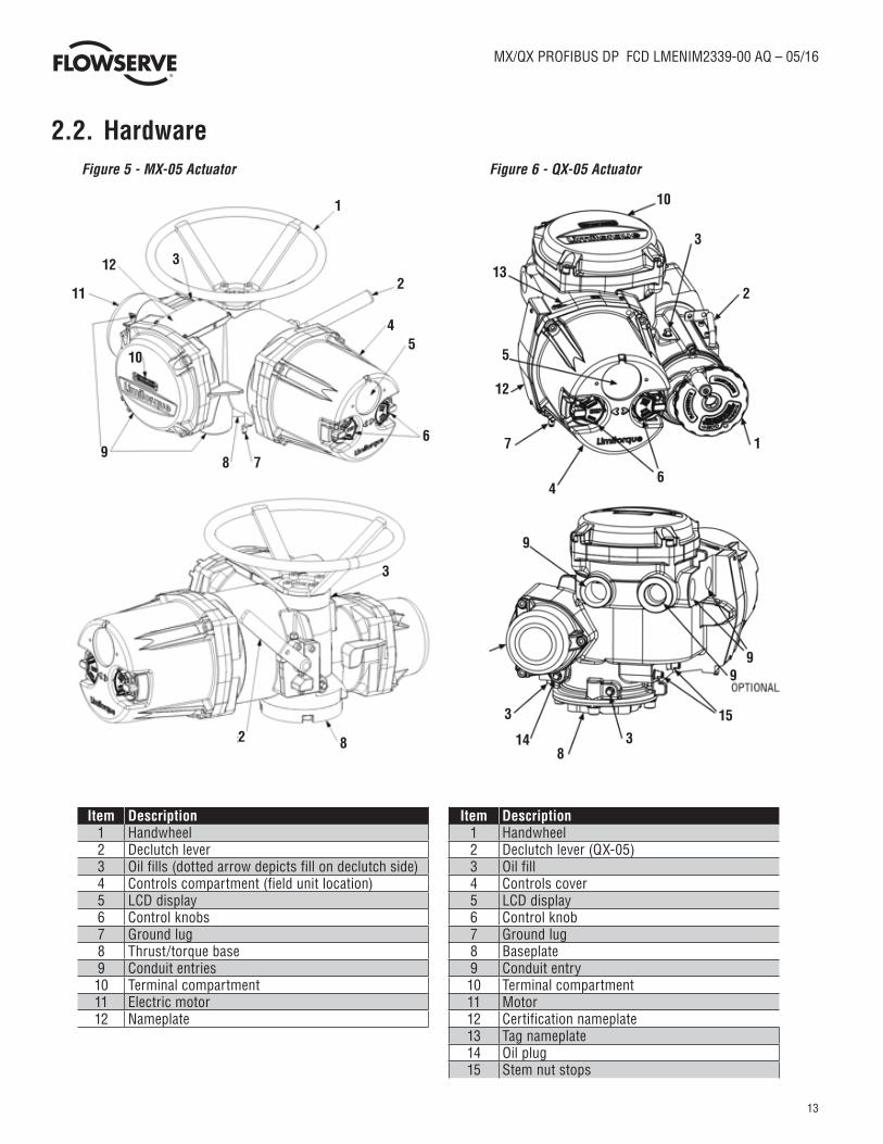
2.2. HardwareFigure 5 - MX-05 Actuator Figure 6 - QX-05 Actuator
Item Description Item Description1 Handwheel 1 Handwheel2 Declutch lever 2 Declutch lever (QX-05)3 Oil fills (dotted arrow depicts fill on declutch side) 3 Oil fill4 Controls compartment (field unit location) 4 Controls cover5 LCD display 5 LCD display6 Control knobs 6 Control knob7 Ground lug 7 Ground lug8 Thrust/torque base 8 Baseplate9 Conduit entries 9 Conduit entry10 Terminal compartment 10 Terminal compartment11 Electric motor 11 Motor12 Nameplate 12 Certification nameplate
13 Tag nameplate14 Oil plug15 Stem nut stops
1
2
45
6
789
11
12 3
10
1
2
3
10
13
12
5
7
46
3
2 8
9
99
38
3
14
15

14
MX/QX PROFIBUS DP FCD LMENIM2339-00 AQ – 05/16
flowserve.com
2.2.1. MX and QX Actuators
The MX and QX actuators are designed for operation of ON-OFF and modulating valve applications. The MX is a multi-turn actuator, while the QX is a quarter-turn actuator.
• Both the MX and QX include the following features:• Non-intrusive setup.• Separately sealed terminal compartment.• Unique absolute encoder for valve position sensing (no battery required).• 32-character LCD for indication and calibration.• Enhanced electronic control, monitoring, and diagnostic capabilities with Built-In (BIST) and LimiGard™ technology.
NOTE: Recommended storage procedures are detailed in the MX and QX Maintenance and Spare Parts Manual LMENIM2314 and
LMENIM3314 respectively. Failure to comply with recommended procedures will void the warranty. For longer-term storage, contact
Flowserve for procedure and recommendations.
2.2.2. MX/QX PB Field Unit
The MX/QX PB field unit interface board is installed in the actuator controls compartment (Figure 23). The MX/QX PB DP version is
shown in Figure 7, and the MX/QX PB Redcom version is shown in Figure 8. Each unit permits the actuator to be controlled as a slave by
one or more master host stations over their respective PROFIBUS network. The MX/QX PB DP Redcom version supports two forms of
redundancy:
a. Flying redundancy provides slave hardware redundancy in the form of a primary and backup channel installed on the PB DP Redcom board. This form is commonly utilized in applications where a single master is present.
b. System redundancy provides for both slave hardware redundancy, in the form of a primary and backup channel installed PB DP Redcom board, and cable redundancy in the form of dual masters connected to the primary and backup channels.
Figure 7 - MX/QX PB DP Field Unit (single channel), Part Number 64-825-0223

15
MX/QX PROFIBUS DP FCD LMENIM2339-00 AQ – 05/16
Figure 8 - MX/QX PB DP Redcom Field Unit (dual channel), Part Number 64-825-0212
The following commands and feedback information are transmitted through this unit:
• OPEN, CLOSE, and STOP commands.• ESD (Emergency Shutdown) commands.• Go-to-position commands.• Redundancy switch-over commands (Profibus DP Redundancy option).• Position feedback.• Actuator status, alarm, and diagnostic messages.• User analog input feedback.• Discrete input feedback.• Discrete output relays.
2.2.3. Network Host Station
The PROFIBUS master is considered to be the network host station, which is typically a DCS, PC, PLC or other micropro-cessor-based PROFIBUS-compliant device. In a mono-master network, the network host device is the only active network node. This is common in a standard Master-Slave PROFIBUS network. In a multi-master network, there are two or more active nodes. This is managed in a token ring, where the token, a uniquely structured message, circulates continuously among the active network nodes. In the case of multiple Masters, only one Master has read/write privileges to its Slaves (passive nodes) at any one time, and the control token is passed continuously in ascending order to all other active network nodes.
2.2.3.1. Token Bus and Token Passing in a Multi-Master Network
During the bus initialization and startup, the bus access control creates the token ring by recognizing the active network nodes in ascending order. The bus access control automatically determines the addresses of all active nodes on the bus, and records them together with its own node address, creating a List of Active Stations.

16
MX/QX PROFIBUS DP FCD LMENIM2339-00 AQ – 05/16
flowserve.com
The Lowest Station Address (LSA) begins with the active token, allowing it to fetch and send data messages to its passive slaves (referred to as polling). At completion of its request frame (polling telegram), and acknowledgement or response frame returned from the slave, the token is passed to the Next Station (NS) with a token telegram. The active node from which the node was passed is called the Previous Station (PS). This continues until the token is being passed from the Highest Station Address (HSA). At completion of the HSA polling telegram, the token is passed to the LSA. The List of Active Stations is required during network operation to remove a faulty active node, or to add a node, without disturbing data on the bus.
2.2.3.2. Token Rotation Time
The time required for the rotation of the token to all active nodes is the token rotation time. The Time Target Rotation (TTR) is adjustable, and is used to specify the maximum allowed time of one rotation.
2.2.3.3. Bus Cycle Time
Based on the number of slaves attached to each master and the amount of data to be transferred, a Bus Cycle Time is calcu-lated by the master. This is the amount of time required for a master to poll all slaves. This, along with the Token Rotation Time, makes PROFIBUS network access deterministic.
2.2.4. Network Cabling for PROFIBIS DP
Network cabling should be in accordance with PROFIBUS Decentralized Periphery (DP) guidelines. To achieve immunity to electromagnetic
interference, ensuring high data integrity, certain cables and guidelines are recommended. Additionally, the following items should be taken
into account when planning the network:
• Transmission rate – Within a network, only one transmission rate can be used; the MX/QX PB DP works at baud rates up to 1.5 Mbps.
• The level of Master and Slave redundancy, if any.• The required number of nodes.• The type of network components needed – terminals, connectors, connecting cables, termination.• The type of cable to be used and its characteristics.
Figure 9 - Typical Cycle Time (Each Station with 2 Bytes I/O)

17
MX/QX PROFIBUS DP FCD LMENIM2339-00 AQ – 05/16
• The number of segments and/or repeaters.• The overall span of the network – adding repeaters and long cable lengths can increase transmission time.• Cable termination – active termination resistors are required at the ends of all segments.• In general, the following rules apply for PROFIBUS networks:• The higher the baud rate, the shorter the distance allowed between nodes.• The higher the baud rate, the shorter the maximum distance of a segment.• The higher the baud rate, the shorter the maximum distance of an entire network.
These distance rules (or limitations) are based on the physical characteristics of the RS-485 topology and are not a limitation of the PROFIBUS protocol. If the distance required between two stations or the total network distance is greater than allowed by the PROFIBUS specifications for copper cable, a conversion to fiber-optic cable may be required. Figure 9 shows the baud rate versus copper cable distance using PROFIBUS.
Table 1 provides the guidelines for maximum segment length versus baud rate.
Table 1- Maximum Segment Length
Table 2 provides the guidelines for maximum network length versus baud rate (assuming the use of up to 9 repeaters).
Table 2 - Total Network Length (with up to nine repeaters)
NOTE: The maximum lengths are estimates and depend on the condition of the actual cable.
Table 3 and Table 4 detail the various types of cable which can be used for network cabling. For additional guidelines, see the following publications:
• PROFIBUS Networks SIMATIC NET 6GK1970-5CA20-0AA1.• PROFIBUS Technical Guideline for PROFIBUS-DP/FMS, Version 1.0, September 1998; PROFIBUS Guideline, Order No.
2.112.• There are different types of electrical data transfer cables:• Standard bus cable.• Standard bus cable with halogen-free sheath (type FRNC).
Baud Rate 9600 to 187.5K 500K 1.5M
Maximum Segment Length (meters) 1,000 400 200
Baud Rate 9600 to 187.5K 500K 1.5M
Total Network Length (meters) 10,000 4,000 2,000

18
MX/QX PROFIBUS DP FCD LMENIM2339-00 AQ – 05/16
flowserve.com
• Cable with PE sheath for use in the food and drug manufacturing industries.• Direct buried cable with additional protective sheath for buried service.• Trailing cable – This is a special cable type which is used where parts of the machine move occasionally or
continuously.• Festooned cable – Comparable to a trailing cable, but has an additional strain relief element.
NOTE: Cable must meet the requirements as listed in Table 3 to ensure reliable network communications.
Table 3 - Recommended PROFIBUS DP Cable Parameters
Table 4 - Recommended PROFIBUS DP Cable Types
Characteristic at 3-20 MHz (ohms) 135 - 165
Operating capacitance (pF/m) < 30
Loop resistance (ohms/km) ≤ 110
Core diameter (mm) > 0.64
Core cross-section (mm2) > 0.34
FC Standard Cable (Siemens AG) 6XV1 830-0EH10
FRNC Cable (Siemens AG) 6XV1 830-0CH10
FC Food Cable (Siemens AG) 6XV1 830-0GH10
FC Ground Cable (Siemens AG) 6XV1 830-3FH10
FC Trailing Cable (Siemens AG) 6XV1 830-3EH10
Festoon Cable (Siemens AG) 6XV1 830-3GH10
PROFIBUS Data Cable (Belden Wire and Cable) 3079A/3076F
PROFIBUS DP Cable (Moeller GmbH) ZB4-900-KB1
PROFIBUS DP Cable (Kerpenwerk GmbH) 7422/7436
PROFIBUS DP Cable (ABB Automation GmbH) NDC110-NO

19
MX/QX PROFIBUS DP FCD LMENIM2339-00 AQ – 05/16
Figure 10 - Copper PROFIBUS Distance vs. Baud Rate Chart
There are several topologies available for both redundant and non-redundant PROFIBUS networks:
• Point-to-point – A single cable from master to slave.• Daisy chain – A single cable daisy chained in and out of each field unit device. End of segment devices only
have one incoming cable.• Tree – Cables and electronic devices (such as repeaters or link modules) are used to branch out from
different points.• Ring – Often implemented with fiber-optic cable which forms a circle or ring when used with Optical Link
Modules. This topology yields redundancy so that any single component fault or cable break does not affect the network (except for the component).
• Combination of the above.

20
MX/QX PROFIBUS DP FCD LMENIM2339-00 AQ – 05/16
flowserve.com
Figure 11 - Cable Topologies
2.2.4.1. Cable Shielding and Grounding for PROFIBUS DP
For best performance, PROFIBUS DP cables should be shielded. Per PROFIBUS Technical Guidelines, the cable shield should be connected at the beginning and end of the segment. Alternatively, a 10-12 AWG ground wire may be run to each MX/QX.
In Figure 12, the grounding point is shown at the junction of the field devices and at each field device.
Figure 12 - Use of Shielded Cable in PROFIBUS DP

21
MX/QX PROFIBUS DP FCD LMENIM2339-00 AQ – 05/16
2.3. Other Network Components
In addition to the network cables, the following components may be used in the PROFIBUS network. Each network is designed based on its application and therefore may not require all of these components.
• Bus Terminal Blocks/Junction Box – Provides multiple connections to the bus (network).• Active Bus Terminal – Provides active termination so that other stations may be powered down for service without
affecting the network.• Connectors – Enable connections to junction boxes, terminators or other connectors. Useful in installations where
devices will be periodically disconnected or when a device is only going to be temporarily disconnected. Some PROFIBUS connectors also include termination resistors for line termination.
• Couplers – Provide one or several connection points to a network segment.• Repeaters – The PROFIBUS Physical Layer (RS-485) dictates that no more than 32 nodes can exist in a shielded
twisted-pair (copper) segment. A node is defined as any station, active or passive, that is connected to the network. Media converters (copper to fiber-optic, fiber-optic to copper) and repeaters do not have PROFIBUS addresses and, therefore, are not included in the 126 possible addressable nodes.
RS-485 repeaters may be used to extend the recommended distance of a segment and “reform” the signal to full voltage levels. Repeaters are included in the total number of allowable nodes per segment; therefore, a segment that begins with a repeater and ends with a repeater may have 30 nodes between them. The maximum number of repeaters allowed in a PROFIBUS network is nine. (Refer to Figure 2.11.)
• Terminators – Used at each end of a PROFIBUS segment to prevent signal reflections.• Power Supplies – Different types of power supplies can be used in a PROFIBUS network:• Non-intrinsically safe power supply.• Standard linear or switching power supply used with a power conditioner.• Intrinsically safe power supply (9-32 VDC).
For cable connecting information on these components, refer to the following:
• Installation Guidelines for PROFIBUS – FMS/DP Version 1.0, PROFIBUS International Order No. 2.112.

22
MX/QX PROFIBUS DP FCD LMENIM2339-00 AQ – 05/16
flowserve.com
Figure 13 - PROFIBUS DP Segments
2.4. Site and Network Cable Preparation
2.4.1. Site Preparation
Prepare the installation site and associated equipment for operation of the MX/QX PB-controlled actuators as follows:
1. Prepare a detailed site plan consisting of the following:• Actuator locations and tag numbers.• Junction boxes and terminal strip locations and tag numbers.• Terminators and power supplies/conditioners, and repeaters.
2. Provide free access to the MX/QX control panel and terminal block for setup, configuration, and troubleshooting.3. Prepare the cable and label all wires. See Section 2.4.2.4. Install power and control wires in separate conduits.5. Install and verify earth grounds. The cable shields should be tied together. Ground the bus shield at the end of each
segment. The MX/QX PB unit should not connect either conductor of the cable to ground at any point in the network. Refer to Sections 2.2.4.1.
NOTE: An effective local earth ground is defined as a low impedance (less than 5 ohms) path to either:
• A ground electrode placed in the close vicinity of the actuator, free of any ground loop currents OR• A safety ground, free of ground loop currents, running from the actuator back to the system ground electrode. If the
signal wiring is run on aerial cable where it may be exposed to high-energy electrostatic discharge (such as lightning), a low impedance path to ground which is capable of high current must be provided a short distance from the actuator as described above OR
• A power distribution grid identifying the impact of power isolation to a particular actuator or group of actuators.

23
MX/QX PROFIBUS DP FCD LMENIM2339-00 AQ – 05/16
2.4.2. Network Cable Preparation
Care must be taken during cable preparation:
• When stripping the insulation, use wire strippers that do not nick the wire.• Use crimp ferrules to prevent stranded wires from getting loose and shorting to other wires.• Use vibration-resistant wiring terminals that hold the ferrule securely.
2.4.2.1. Network Cable Connection to the MX/QX PB Unit
The field device is connected to the PROFIBUS network through the MX/QX terminal block.
The PROFIBUS DP network cable is connected to the terminal block as shown in Figure 14, Figure 15, or Figure 16.
NOTE: The MX/QX PB DP device is sensitive to polarity. Cable polarity should be maintained through all connection points.
Figure 14 - PROFIBUS DP, p/n 64-825-0223, Connection to Terminal Blocks
Figure 15 - PROFIBUS DP Redcom, p/n 64-825-0212, Connections (Flying Redundancy, single line, with single master)

24
MX/QX PROFIBUS DP FCD LMENIM2339-00 AQ – 05/16
flowserve.com
Figure 16 - PROFIBUS DP Redcom, p/n 64-825-0212, Connections (Flying, two line, or System Redundancy options)
• Shielded twisted-pair cables in compliance to PROFIBUS standards must be used.• Shields are connected to earth ground. PB/DP connects at the ends of each segment. • Clean earth-ground connection (less than 5 ohms) provides noise protection and a clear, safe path for surge currents.
Prepare the network cable for connection to the MX/QX terminals as follows:
CAUTION: Strip stranded conductors carefully, do not damage the strands. This will weaken the conductor and can cause the conductor to break. This type of damage may not be apparent and failure can occur without warning.
1. Remove two to three inches (5 to 8 cm) of the outer jacket of the cable as shown in Figure 17. Do not cut or nick the shield or the insulated conductors.
Figure 17 - Removing Outer Plastic Jacket
NOTE: Excess cable should be cut and removed, not coiled or looped, to prevent noise induction into the network.

25
MX/QX PROFIBUS DP FCD LMENIM2339-00 AQ – 05/16
2. Separate the cable parts. Unbraid the shield and peel back the shield to the same point where the outer jacket was removed as shown in Figure 18.
Figure 18 - Separating Cable Parts
3. Cut away the foil shield. Strip the insulation from the conductors approximately 0.4 inch (1 cm) as shown in Figure 19.
Figure 19 - Stripping Conductors

26
MX/QX PROFIBUS DP FCD LMENIM2339-00 AQ – 05/16
flowserve.com
4. Apply heat-shrink tubing to insulate the braided shield and to provide stress relief to the cable as shown in Figure 20.
Figure 20 - Apply Heat-Shrink Tubing
CAUTION: Do not melt the insulation during the application of heat-shrink tubing.
5. Install ring tongue connectors as shown in Figure 21.
NOTE: Flowserve recommends the use of Thomas and Betts #RZ22-6 for optimum results.
Figure 21 - Ring Tongue Connections

27
MX/QX PROFIBUS DP FCD LMENIM2339-00 AQ – 05/16
6. Connect the network cables to the MX/QX terminal block as shown in Figure 22.
Table 5 - Terminal Block Connections
NOTE: Terminal 3 must be connected to earth ground in each actuator for field unit surge suppression.
NOTE: Ground each segment of the cabling at each field device unit. See Section 2.2.4.1. Verify the actuator is properly grounded.
Figure 22 - Connecting Network Cable to the MX/QX Terminal Block
7. Connect the cable shields to each other inside the unit. Do not connect them to the unit in any way. The networkshield should be grounded at the end of each segment. For surge suppression, Terminal 3 must be tied to earth ground in both DP applications.
Terminal Block Number DP Connection
1 PBDP-B (-) Out
2 PBDP-B (+) Out
3 Surge/Ground
4 PBDP-A (-) Out
5 PBDP-A (+) Out
13 PBDP-A (+) In
14 PBDP-A (-) In
15 PBDP-B (-) In
16 PBDP-B (+) In

28
MX/QX PROFIBUS DP FCD LMENIM2339-00 AQ – 05/16
flowserve.com
2.4.2.2. Network Cable Connection to the Host System
For instructions on connecting to the host system, see the applicable host system/station. There are several topologies for the network detailed in Installation Guideline for PROFIBUS-DP/FMS, Version 1.0, September 1998.
2.4.3. MX/QX PB Device Installation
The MX/QX PB board is located in the electrical housing of the actuator unit. The PB board has four standoffs and mounts on top of the main processor board as shown in Figure 23. An optional Input/Output (I/O) board may also be present. The PB and I/O boards may be inserted in any order on top of the main processor board. For detailed installation instructions, refer to the MX or QX Maintenance and Spare Parts Manuals, LMENIM2314 or LMENIM3311, respectively.
Figure 23 - MX/QX PB DP Board Mounted to MX/QX Main Board
Figure 24 - MX/QX PB DP and Option Boards Mounted to MX/QX Main Board

29
MX/QX PROFIBUS DP FCD LMENIM2339-00 AQ – 05/16
2.5. MX/QX PB Device Setup
The MX/QX PB option enables the actuator to be controlled by a PROFIBUS communications signal. If the option has been purchased,
it is automatically enabled.
NOTE: If the PB option has not been purchased, the screens for changing PB will not be available. To add the option, please consult
Flowserve Limitorque service at (434) 528-4400.
Figure 25 - MX/QX PB DP Setup Sequence for single channel (p/n 64-825-0223) boards

30
MX/QX PROFIBUS DP FCD LMENIM2339-00 AQ – 05/16
flowserve.com
Figure 26 - MX/QX PB DP Redcom Setup Sequence for dual channel (p/n 64-825-0212) boards
Figure 25 illustrates the setup sequence for the single channel MX/QX PB DP field unit and Figure 26 illustrates the setup sequence for the dual channel MX/QX PB DP Redcom field unit. For proper operation, either Position Mode or Open/Close Mode must be selected.
Follow these steps to enter and configure the setup mode:
1. Proceed through the “Setup to the CHANGE PBDP?” menu option. 2. Select YES to proceed to the “PBDP STATUS (ON) - OK?” menu option. Select NO to change the setting between
ON and OFF as this menu enables or disables the functionality of the PB DP board. Select YES when the desired operational status is displayed.
3. For Profibus DP Redcom boards (p/n 64-825-0212), the menu will then show the REDUNDANCY MODE display. Select NO to cycle through the following redundancy modes: Non-redundant, Simple Flying Redundant with no line redundancy, Simple Flying Redundant with line redundancy, Full Flying Redundant with no line redundancy, Full Flying Redundant with line redundancy, and Full System Redundant. Select YES when the desired redundancy mode is displayed. For single channel Profibus DP boards (64-825-0223), the mode will always be non-redundant and this menu option is not shown.
31
MX/QX PROFIBUS DP FCD LMENIM2339-00 AQ – 05/16
2.5.1. Proportional Band
Proportional band is the range of errors between the position and demand signal that will produce reduced speed (pulsing). The default value is 5%.
To change from the default value, select NO until the required value is displayed. The value is adjustable between 1% and 100%, in 1% increments.
2.5.2. Deadband
The default deadband value is 2%. For error signals less than this, no motion occurs.
The deadband should be wide enough to prevent “hunting” of the actuator, but as low as possible to give adequate response to changes in the error signal. To change from the default, select NO to adjust the value between 1% and 50%, in 1% increments to suit the application.
2.5.3. Valve Data
Valve data may be stored in the MX/QX PB parameter 35 in Table 13 for use by the host system. Refer to Bulletin LMENIM2306 (MX) or LMENIM3306 (QX), respectively for instructions to edit data for the valve serial number, model and type.
4. The unit will display the “PRIMARY ADDRESS # - OK?” menu option. Select NO to change the Profibus network address (0-61 for Flying Redundancy modes, 0-125 for System and non-redundant modes). For Flying redundant modes, the backup address will automatically be the primary address plus 64. Select YES when the desired Profibus network address is displayed.
5. From the “ANALOG SCALE” menu, select NO to change the scale range. Select YES when the desired range is displayed. 6. From the “ESD ACTION” menu, select NO to change the Emergency Shutdown action. Options are: IGNORE, STOP, OPEN,
CLOSE, and POSITION. Select YES when the desired action is displayed. 7. If POSITION is chosen as the ESD action, the MOVE TO (XXX%)-OK? is displayed next. Select NO to change the desired
percent open position and select YES when done.8. From the “COMM LOSS ACTION” menu, select NO to change the Communication Loss action. Options are: IGNORE, STOP,
OPEN, CLOSE, and POSITION. Select YES when the desired action is displayed.9. If POSITION is chosen as the communication loss action, the MOVE TO XXX% is displayed next. Select NO to change the
desired percent open position and select YES when done.10. From the “COMM LOSS DELAY” menu, select NO to change the communication loss action time. Select YES when the
desired time is displayed. 11. From the “CHAN-A TERMINATION” menu, select NO to change the enabling/disabling of the built-in termination
capabilities for the channel A network. Select YES to accept the current ENABLED or DISABLED setting.12. On dual channel boards (p/n 64-825-0212) and when a redundant mode is selected, the “CHAN-B TERMINATION” menu
is displayed next. Select NO to change the enabling/disabling of the built-in termination capabilities for the channel B network. Select YES to accept the current ENABLED or DISABLED setting.
13. From the “OPEN/CLOSE MODE” menu, select NO to toggle the actuator mode between OPEN/CLOSE and POSITION. In OPEN/CLOSE mode, the host can only fully open or fully close the valve. Select YES when the desired mode is displayed.
14. Proceed to configure the proportional band and deadband as discussed in sections 2.5.1 and 2.5.2, respectively.

32
MX/QX PROFIBUS DP FCD LMENIM2339-00 AQ – 05/16
flowserve.com
2.6. MX/QX PB Device Description, Capabilities and Device Type Manager File Installation
2.6.1. MX/QX PB Device Description
A Configuration File (a GSD or EDD file) describes the communication objects in a PROFIBUS device. In the host system, the configuration device can use Electronic Device Description (EDD) files or GSD file to configure a PROFIBUS system without having the device online. Some host systems need both EDD and GSD files. Refer to your host system and software docu-mentation for the files that are needed. Please contact Flowserve Limitorque for EDD files.
The GSD (characteristics) files are downloaded from the PROFIBUS or Flowserve websites into the host system. These files are required by the host system for proper configuration and addressing. There are two different GSD files:
FLNR0F4C.GSD for Profibus DP boards (p/n 64-825-0223, single channel)
FLSV0F4C.GSD for Profibus DP Redcom boards (p/n 64-825-0212, dual channel)
The PROFIBUS website is www.profibus.com and the Flowserve website is www.flowserve.com. Literature and GSD files can be found at www.flowserve.com/Support/Software-Downloads#Limitorque. The GSD file for the legacy Profibus DP/PA board (p/n 64-825-0046-4) is FLSV07A0.GSD and should not be used for the newer Profibus DP boards
2.6.2. MX/QX PB Device Type Manager
The Device Type Manager (DTM) provides an interface between its specific application software and a Network Host Station’s Field Device Tool (FDT) frame. The DTM can be integrated into FDT frame applications to allow users to perform offline and online parameterization, configuration, and status and diagnostic retrieval. A separate GSD file download is unnecessary when using the DTM. The DTM file can be downloaded from the Flowserve website: www.flowserve.com.
2.7. Installation Verification
2.7.1. Network Cabling Installation Verification
After installation is complete and prior to operation, inspect the network cable and its connection to each field device.
NOTE: Units should be disconnected from power. The network should be disconnected from the host device.
Check for the following:
1. There should not be:• Nicks in the insulation – this can cause a short to the grounded shield.• Cut strands in a stranded conductor – this can cause a poor connection and eventually an open circuit.• Cable armor shorted to the cable shield/drain wire. This may not be at ground potential and could be subject to
lightning surges.
2. Shield/drain wires grounded only at one point in the segment to avoid ground loop problems.
3. Ground/earth connections should be at true ground potential and effective at all times. See Section 2.4.1 for details.

33
MX/QX PROFIBUS DP FCD LMENIM2339-00 AQ – 05/16
2.7.2. MX/QX PB Device Installation Verification
Verify the field device is installed as follows:
1. Enter the Setup mode as detailed in the MX or QX Installation and Operation Manual, LMENIM2306 or LMENIM3306
respectively.
2. In the Setup mode, use the black control knob to select YES to the main menu selection “VIEW DIAGNOSTICS?”
3. Select YES to the display “VIEW HARDWARE?” The “VIEW HARDWARE” routine will enable some of the actuator
components to be reviewed for integrity. These components are continuously monitored.
4. Select YES to scroll through the menu selections. For a PB DP field unit, the display will eventually read PBDP (OK) - Next?
5. To return to the normal display, use the red knob to select either LOCAL or REMOTE.
2.7.3. MX/QX PB Device and MX/QX PB Redcom Device Differentiation
To verify which PBDP board (single channel p/n 64-825-0223 or dual channel p/n 64-825-0212), is installed, use the menu as follows:
6. Enter the Setup mode as detailed in the MX or QX Installation and Operation Manual, LMENIM2306 or LMENIM3306 respectively.
7. In the Setup mode, use the black control knob to select YES to the main menu selection “VIEW DIAGNOSTICS?”8. Select YES to the display “VIEW IDENTIFICATION?” The “VIEW IDENTIFICATION” routine will enable some of the
actuator components to be reviewed for version numbers. These components are queried during actuator power on and initialization.
9. Select YES to scroll through the menu selections. For a PB DP field unit, the display will eventually read “PBDP BOARD?” and show the internal board identification number.
a For the single channel Profibus DP board, p/n 64-825-0223, the second line will read “ID = 6”. b For the dual channel Profibus DP Redcom board, p/n 64-825-0212, the second line will read “ID = 5”. c If “PBDP Firmware #” is displayed (the # may be 2122 or similar), the legacy Profibus DP board, p/n 64-825-0046-4, is installed.
10. To return to the normal display, use the red knob to select either LOCAL or REMOTE.
2.8. Configuration Confirmation
Field device operation cannot be verified until the complete PROFIBUS system is operational. However, routine checks can be performed to verify many functions.
2.8.1. Checking Connections
Verify that all connections, including network data wires, shield ground, discrete inputs, discrete outputs, analog inputs and analog outputs are in accordance with MX/QX wiring diagrams and MX/QX PB device diagrams in Section 2.4.
34
MX/QX PROFIBUS DP FCD LMENIM2339-00 AQ – 05/16
flowserve.com
2.8.2. View Settings
Refer to the MX or QX Installation and Operation Manual, LMENIM2306 or LMENIM3306 respectively, to access the view settings menu. Verify the settings as follows:
1. From the VIEW SETTINGS display, scan to the VIEW PB/DP option.2. From the VIEW PB/DP display, select YES and check that the PB/DP status is ON. This confirms that PB/DP is enabled.3. If the MX/QX contacts are to be controlled via the network to control external equipment, from the “VIEW PB/DP” display,
select NO and obtain the “VIEW STATUS AND ALARM CONTROL?” display. Verify that the digital outputs, S-1 and S-2 are set for “Network” control.
2.8.3. Checking the Normal Display
Place the selector switch in LOCAL or REMOTE position. The valve position will be indicated at the top of the display. For a PB DP field unit, STATUS OK, PBDP COMM LOSS, CHAN-A PRIMARY, CHAN-B PRIMARY or PLC OFFLINE should be indicated at the bottom of the display.
2.8.3.1. STATUS OK
If STATUS OK is displayed, then the field device is sufficiently powered and communicating with the host system. This may cycle to CHAN-A PRIMARY, CHAN-B PRIMARY, or PLC OFFLINE.
2.8.3.2. CHAN-A PRIMARY
The text CHAN-A PRIMARY will alternate with STATUS OK when the host on the channel A network is actively controlling the actuator. This applies to both single channel (p/n 64-825-0223) dual channel (p/n 64-825-0212) boards.
2.8.3.3. CHAN-B PRIMARY
For Profibus DP Redcom boards (p/n 64-825-0212) with redundancy enabled, the text CHAN-B PRIMARY will alternate with STATUS OK when the host on the channel B network is actively controlling the actuator. This does not apply to single channel (p/n 64-825-0223) boards.
2.8.3.4. PLC OFFLINE
When the network cyclic traffic detected, the text PLC OFFLINE will alternate with STATUS OK to indicate when the host is offline (in STOP or configuration modes).
2.8.3.5. PBDP COMM LOSS
This text is display when data exchange tokens from the host cannot be detected. This could be due to a number of factors, including problems with the host/master station and/or the network. Check all local connections and configurations. If these are correct and the PBDP COMM LOSS is still displayed, then the solution to this problem must await full system commissioning.
2.8.3.6. PBDP FAILED / HARDWARE FAILURE
If PBDP FAILED and HARDWARE FAILURE status messages begin to display (the two messages will alternate about every second), the Profibus network board is not responding or has failed. Check the “VIEW DIAGNOSTICS” in section 2.7.2 as a starting point to diagnose the issue.

35
MX/QX PROFIBUS DP FCD LMENIM2339-00 AQ – 05/16
3. Software3.1. Profibus Protocol
The fieldbus system uses the PROFIBUS fieldbus protocol to communicate over the PROFIBUS network with other PROFIBUS devices. The
signals are encoded using the Non-Return to Zero (PROFIBUS DP) technique. The signals are called synchronous serial because the clock
information is embedded in the serial stream. The protocol uses built-in error checking rules when processing data.
3.2. Cyclic ModulesThe PROFIBUS DP network board supports cyclic (DPV0) and acyclic (DPV1) communications. The cyclic information is configurable
by selecting a module with the desired information set as shown in Table 6. The cyclic module number is selected in the host system’s
network configuration manager that utilizes the GSD file. The default module is ‘1’ and it provides all available information to the system.
A different module may be used to selectively provide less information and the network configuration manager tool may display the GSD
abbreviation when entering this information.
Table 6 - Cyclic Modules
Module 1 2 3 4 5 6 7 8 9 10
Para
met
ers
Setpoint (Target, Move-to value) √ √ √ √ √ √ √ √ √
Actuator Command √ √ √ √ √ √ √ √
Relay Command √ √ √
Actuator Position √ √ √ √ √ √ √
Actuator Torque √ √ √ √ √ √ √
Actuator Status (Table 7) √ √ √ √ √ √ √ √ √ √
Actuator Faults (Table 8) √ √ √ √ √ √ √ √ √ √
Actuator Indications (Table 9) √ √ √ √ √ √ √
User IO (Table 10) √ √ √ √ √
Network Status (Table 11) √ √ √ √ √ √ √ √ √ √
GSD Abbreviation
ALL
ALL
SP+A
S+AF
+NS
SP+A
C –A
I-UI
O
SP+A
C –A
I
SP+A
C –U
IO
SP –
UIO
ALL
–AP-
AT
SP+A
C –A
P-AT
ALL
–UIO
AC A
LL

36
MX/QX PROFIBUS DP FCD LMENIM2339-00 AQ – 05/16
flowserve.com
Table 7 - Actuator Status
Bit Description0 Opened1 Closed2 Opening3 Closing4 Stopped In Mid Travel5 Knob In Remote6 Knob In Local7 Knob In Stop8 Local ESD Active9 Network ESD Active10 Open Inhibit Active11 Close Inhibit Active12 CSE In Local Stop13 Open Contactor14 Close Contactor15 PST Active
Table 8 - Actuator Faults
Bit Description
0 Monitor Relay Energized1 Valve Jam2 Manual Move3 Over Torque4 Motor Over Temperature5 Phase Lost6 Encoder Fault7 Contactor Fault8 Motor Controller Fault9 Mainboard Memory Fault10 Knob Fault11 Open Torque Switch12 Close Torque Switch13 Open Limit Switch14 Close Limit Switch15 Reserved
Table 9 - Actuator Indications
Bit Description0 Encoder Warning1 Motor Temperature Warning2 Phase Reverse3 Line Frequency Too Low4 Line Voltage Too Low5 Open Torque Timer Expired6 Close Torque Timer Expired7 Mainboard Analog Input Lost8 Analog Board-1 Analog Input Lost9 Analog Board-2 Analog Input Lost10 Analog Board-1 Fail11 Analog Board-2 Fail12 Digital Output Board-1 Fail13 Digital Output Board-2 Fail14 Reserved15 Reserved
Table 10 - User I/O
Bit Description0 S1/R11 S2/R22 R33 R44 R55 R66 R77 R88 User 0 - Default ESD9 User 1 - Default Open Inhibit10 User 2 - Default Close Inhibit11 User 3 - Stop12 User 4 - Open13 User 5 - Close14 Reserved15 CSE At User 2

37
MX/QX PROFIBUS DP FCD LMENIM2339-00 AQ – 05/16
Table 11 - Network Status
3.3. DPV0 Parameters
The PROFIBUS DP network board can also be configured via DPV1 and has the following available parameters as shown in Table 12.
Parameters 1 to 11 will be in the Ext_User_Prm_Data within the GSD so they can be configured by DPV0 users. This allows basic configuration at startup by GSD initialization only if ‘Permit GSD Configuration’ is changed to 0 (permit). Otherwise, the configuration of these parameters will be via PDM/EDDL or DTM or the Main board SETUP menu with ‘Permit GSD Configuration’ left as 1 (don’t allow GSD write).
Table 12 – DPV0 Parameters
# Type Access Parameter Name Description
1 U8 R/W GSD_CONFIGPermit GSD Configuration0 = Param # 2 to 11 write using GSD USER_PARAM only.1 = Param # 2 to 11 don't allow GSD write, use EDDL, SETUP Menus or DTM to configure.
2 U8 R/W REDUNDANCY_MODE
Redundancy Mode
0 = Non redundant mode.1 = Simple flying without line redundancy.2 = Simple flying with line redundancy.3 = N/A4 = Full flying without line redundancy.5 = Full flying with line redundancy.6 = Full system redundancy.
3 U8 R/W NW_ANALOG_SCALE
Network Analog Scaling0 = Analog Scale: 0 to 100.1 = Analog Scale: 0 to 255.2 = Analog Scale: 0 to 4095.3 = N/A4 = Future (Analog Scale: 0 to 65535).
Bit Description
0 SPI To Mainboard Failure1 PROFIBUS DP Board Failure2 PROFIBUS DP Communication Loss Timeout3 PROFIBUS DP Channel-A Failure4 PROFIBUS DP Channel-B Failure5 PROFIBUS DP Channel-A Primary6 PROFIBUS DP Channel-B Primary

38
MX/QX PROFIBUS DP FCD LMENIM2339-00 AQ – 05/16
flowserve.com
# Type Access Parameter Name Description
4 U8 R/W NW_ESD_ACTION
Network Emergency Shutdown Action0 = ESD Action: Ignore.1 = ESD Action: Stop.2 = ESD Action: Close.3 = ESD Action: Open.4 = ESD Action: Position.
5 Float R/W NW_ESD_POSITIONNetwork Emergency Shutdown PositionMinimum value: 0.0Maximum value: 100.0 (multiply by ten when pass to main)
6 U8 R/WNW_COMM_LOSS_
ACTION
Communication Loss Action0 = Comm Loss Action: None.1 = Comm Loss Action: Stop.2 = Comm Loss Action: Close.3 = Comm Loss Action: Open.4 = Comm Loss Action: Position.
7 Float R/WNW_COMM_LOSS_
POSITION
Communication Loss PositionMinimum value: 0.0Maximum value: 100.0 (multiply by ten when pass to main)
8 U8 R/WNW_COMM_LOSS_
DELAY
Communication Loss Delay1 to 120 (seconds)
9 U16 R/W PROFIBUS_CONTROL
Termination, Actuation mode, Precision and Force commandBit 0:Clear = Profibus DP channel-A termination set to Disabled.Set = Profibus DP channel-A termination set to Enabled.
Bit 1:Clear = Profibus DP channel-B termination set to Disabled.Set = Profibus DP channel-B termination set to Enabled.
Bit 2:Clear = Actuation mode set to Open/Close.Set = Actuation mode set to Position.
Bit 3:Clear = Precision xxx%.Set = Precision xxx.x%.
Bit4:Set = Force Switchover (edge triggered from 0 to 1).
10 Float R/W DEADBAND
DeadbandMinimum value: 0.1 for QXM units and 0.5 for MX and QX units.Maximum value: 50.0 or Proportional band value minus 0.5 whichever is less. Deadband
must always be less than Proportional Band.
11 Float R/WPROPORTIONAL_
BAND
Proportional BandMinimum value: Deadband value plus 0.5 (must always be > deadband).Maximum value: 100.0

39
MX/QX PROFIBUS DP FCD LMENIM2339-00 AQ – 05/16
3.4. DPV1 ParametersAll of the following parameters are accessible via acyclic communication. Additionally parameters from 21 to 30 are also
accessible via cyclic communication.
Table 13 - DPV1 Parameters
# Type Access Parameter Name Member Description
12 U32 R/W NE107_FAILURE_MASKNE107 Failure MaskThis sets the bit patterns that will trigger the associated indica-tion. See Table 15 for bit definitions.
13 U32 R/W NE107_FUNCTION_CHECK_ MASKNE107 Function Check MaskThis sets the bit patterns that will trigger the associated indica-tion. See Table 16 for bit definitions.
14 U32 R/W NE107_OUT_OF_SPEC_MASKNE107 Out of Specification MaskThis sets the bit patterns that will trigger the associated indica-tion. See Table 17 for bit definitions.
15 U32 R/W NE107_MAINT_REQUEST_ MASKNE107 Maintenance Request MaskThis sets the bit patterns that will trigger the associated indica-tion. See Table 18 for bit definitions.
16 U8 R NE107_INDICATIONS
NE107 IndicationsThis is a bit mask to indicate the presence of NE107 informa-tion:Bit 0 set = Device OKBit 1 set = Failure Information presentBit 2 set = Function Check Information presentBit 3 set = Out of Spec Information presentBit 5 set = Maintenance Information present
17 U32 R NE107_FAILURE_INFONE107 Failure InformationSee Table 15 for bit definitions.
18 U32 R NE107_FUNCTION_CHECK_ INFONE107 Function Check InfoSee Table 16 for bit definitions.
19 U32 R NE107_OUT_OF_SPEC_INFONE107 Out of Spec InformationSee Table 17 for bit definitions.
20 U32 R NE107_MAINT_REQUEST_ INFONE107 Maintenance Request InfoSee Table 18 for bit definitions.
21 U16 R/W ACT_SETPOINTSetpoint (Target, Move-to value)Minimum value: 0.Maximum value: Analog scale maximum value.
22 U16 R/W ACT_COMMAND
Actuator Command0 = No command.1 = Stop command.2 = Close command.3 = Open command.4 = Stop network ESD.5 = Start network ESD.

40
MX/QX PROFIBUS DP FCD LMENIM2339-00 AQ – 05/16
flowserve.com
# Type Access Parameter Name Member Description
23 U16 R/W NW_CTRL_RLY_COMMAND
Network controlled relay commandsBit 0 clear: De-energize S1 or R1 relay.Bit 0 set: Energize S1 or R1 relay.Bit 1 clear: De-energize S2 or R2 relay.Bit 1 set: Energize S2 or R2 relay.Bit 2 clear: De-energize R3 relay.Bit 2 set: Energize R3 relay.Bit 3 clear: De-energize R4 relay.Bit 3 set: Energize R4 relay.Bit 4 clear: De-energize R5 relay.Bit 4 set: Energize R5 relay.Bit 5 clear: De-energize R6 relay.Bit 5 set: Energize R6 relay.Bit 6 clear: De-energize R7 relay.Bit 6 set: Energize R7 relay.Bit 7 clear: De-energize R8 relay.Bit 7 set: Energize R8 relay.Bit 15 clear: Indicates bits 0-7 are unknown. Clear this bit when not changing any bits 0 through 7.Bit 15 set: Indicates bits 0-7 are valid. Set this bit whenever changing any bits 0 through 7.
24 U16 R ACT_POSITION Current Position25 U16 R ACT_TORQUE Current Torque
26 U16 R ACT_STATUSActuator StatusSee Table 7
27 U16 R ACT_FAULTSActuator FaultsSee Table 8
28 U16 R ACT_INDICATIONSActuator IndicationsSee Table 9
29 U16 R USER_IOUser I/OSee Table 10
30 U16 R NW_STATUSNW StatusSee Table 11
31 U16 R CYCLIC_DATA_CFGCyclic Exchange ConfigurationMinimum value: 0.Maximum value: 10.
32
U8[4] R
INTERFACE_VERSIONS
SOFTWARE_REVISION Profibus DP board software revision numberU16 R HARDWARE_REVISION Profibus DP board hardware revision number
U8[4] R DP_STACK_REVISION Profibus DP board communication stack revision number
U16 RSOFTWARE_RELEASE_ NUMBER
Profibus DP board software release number
U8[4] R BOOTLOADER_REVISION Profibus DP board bootloader revision number.
33
char[16] R
ACT_INFO
ACT_MANUFACTURER Actuator ManufacturerU8 R ACT_TYPE Actuator TypeU8 R ACT_ID Actuator Identifier
char[32] R ACT_MODEL_NUMBER Actuator Model Numberchar[8] R ACT_SERIAL_NUMBER Actuator Serial Number
char[22] R ACT_QA_DATA Actuator QA Data34 U32 R ACT_SERVICE_TIME Actuator Service Time
U8[4] R BOOTLOADER_REVISION Profibus DP board bootloader revision number.
41
MX/QX PROFIBUS DP FCD LMENIM2339-00 AQ – 05/16
# Type Access Parameter Name Member Description
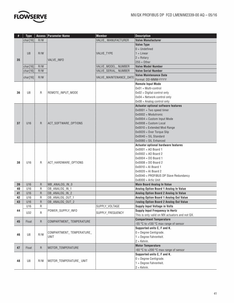
35
char[16] R/W
VALVE_INFO
VALVE_ MANUFACTURER Valve Manufacturer
U8 R/W VALVE_TYPE
Valve Type0 = Undefined1 = Linear2 = Rotary255 = Other
char[16] R/W VALVE_MODEL_ NUMBER Valve Model Numberchar[16] R/W VALVE_SERIAL_ NUMBER Valve Serial Number
char[16] R/W VALVE_MAINTENANCE_DATEValve Maintenance DateFormat: DD-MMM-YYYY
36 U8 R REMOTE_INPUT_MODE
Remote Input Mode0x01 = Multi-control0x02 = Digital control only0x04 = Network control only0x08 = Analog control only
37 U16 R ACT_SOFTWARE_OPTIONS
Actuator optional software features0x0001 = Two speed timer0x0002 = Modutronic0x0004 = Custom Input Mode0x0008 = Custom Local0x0010 = Extended Mod Range0x0020 = Over Torque Slip0x0040 = SIL Standard0x0080 = SIL Enhanced
38 U16 R ACT_HARDWARE_OPTIONS
Actuator optional hardware features0x0001 = AO Board 10x0002 = AO Board 20x0004 = DO Board 10x0008 = DO Board 20x0010 = AI Board 10x0020 = AI Board 20x0040 = PROFIBUS DP Slave Redundancy0x8000 = Artic Unit
39 U16 R MB_ANALOG_IN_0 Main Board Analog In Value40 U16 R OB_ANALOG_IN_1 Analog Option Board 1 Analog In Value41 U16 R OB_ANALOG_IN_2 Analog Option Board 2 Analog In Value42 U16 R OB_ANALOG_OUT_1 Analog Option Board 1 Analog Out Value43 U16 R OB_ANALOG_OUT_2 Analog Option Board 2 Analog Out Value
44U16 R
POWER_SUPPLY_INFOSUPPLY_VOLTAGE Supply Input Voltage in Volts
U32 R SUPPLY_FREQUENCYSupply Input Frequency in HertzThis is only valid on MX actuators and not QX.
45 Float R COMPARTMENT_ TEMPERATURECompartment Temperature-55 °C to +130 °C max range of sensor
46 U8 R/WCOMPARTMENT_ TEMPERATURE_UNIT
Supported units C, F and K.0 = Degree Centigrade.1 = Degree Fahrenheit.2 = Kelvin.
47 Float R MOTOR_TEMPERATUREMotor Temperature-60 °C to +200 °C max range of sensor
48 U8 R/W MOTOR_TEMPERATURE_ UNIT
Supported units C, F and K.0 = Degree Centigrade.1 = Degree Fahrenheit.2 = Kelvin.
42
MX/QX PROFIBUS DP FCD LMENIM2339-00 AQ – 05/16
flowserve.com
# Type Access Parameter Name Member Description
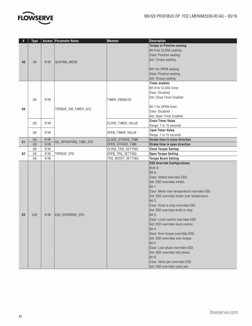
49 U8 R/W SEATING_MODE
Torque or Position seatingBit 0 for CLOSE seating:Clear: Position seating.Set: Torque seating.
Bit1 for OPEN seating:Clear: Position seating.Set: Torque seating.
50
U8 R/W
TORQUE_SW_TIMER_CFG
TIMER_ENABLED
Timer enablesBit 0 for CLOSE timer:Clear: DisabledSet: Close Timer Enabled
Bit 1 for OPEN timer:Clear: DisabledSet: Open Timer Enabled
U8 R/W CLOSE_TIMER_VALUEClose Timer ValueRange: 1 to 15 seconds
U8 R/W OPEN_TIMER_VALUEOpen Timer ValueRange: 1 to 15 seconds
51U8 R/W
QX_OPERATING_TIME_CFGCLOSE_STROKE_TIME Stroke time in close direction
U8 R/W OPEN_STROKE_TIME Stroke time in open direction
52U8 R/W
TORQUE_CFGCLOSE_TRQ_SETTING Close Torque Setting
U8 R/W OPEN_TRQ_SETTING Open Torque SettingU8 R/W TRQ_BOOST_SETTING Torque Boost Setting
53 U32 R/W ESD_OVERRIDE_CFG
ESD Override ConfigurationsByte 0:Bit 0:Clear: Inhibit overrides ESD.Set: ESD overrides inhibit.Bit 1:Clear: Motor over temperature overrides ESD.Set: ESD overrides motor over temperature.Bit 2:Clear: Knob in stop overrides ESD.Set: ESD overrides knob in stop.Bit 3:Clear: Local control overrides ESD.Set: ESD overrides local control.Bit 4:Clear: Over torque overrides ESD.Set: ESD overrides over torque.Bit 5:Clear: Lost phase overrides ESD.Set: ESD overrides lost phase.Bit 6:Clear: Valve jam overrides ESD.Set: ESD overrides valve jam.

43
MX/QX PROFIBUS DP FCD LMENIM2339-00 AQ – 05/16
# Type Access Parameter Name Member Description
53 U32 R/W ESD_OVERRIDE_CFG
Bit 7:Clear: Oil over temperature overrides ESD.Set: ESD overrides oil over temperature.
Byte 1:Bit 0:Clear: Torque switch timer overrides ESDSet: ESD overrides torque switch timerBits 2-5:Available for future useBit 6:Clear: ESD uses 2-speed timer settings.Set: ESD ignores 2-speed timer settings.Bit 7:Clear: Network ESD overrides ESDSet: ESD overrides network ESD
Byte 2:Bit 0:Clear: Motor fault overrides ESDSet: ESD overrides motor faultBit 1:Clear: Motor controller fault overrides ESDSet: ESD overrides motor controller fault.Bit 2:Clear: Line voltage too low/high overrides ESDSet: ESD overrides line voltage too low/high.Bits 3-7:Available for future use
Byte 3:Bits 0-7:Available for future use
54U8 R/W
PARTIAL_STROKE_ TEST_REQUESTPST_COMMAND
PST Command0 = None.1 = PST start command.2 = PST stop command.3 = Request last PST results.See the FAQ section on how to run a PST test.
Float R/W PST_TARGET_POSITIONPST Target Positon in % OpenRange: 0.0 to 100.0
55
U8 R
PARTIAL_STROKE_ TEST_RESPONSE
PST_STATUS
PST Status0 = Not started.1 = In progress.2 = Completed.3 = Stop command sent by user.
U8 R PST_RESULT
PST Result0 = Not started.1 = Waiting.2 = Passed.3 = Failed.
U8 R PST_MAX_TORQUE Highest Measured Torque during PST

44
MX/QX PROFIBUS DP FCD LMENIM2339-00 AQ – 05/16
flowserve.com
# Type Access Parameter Name Member Description
56
U32 R
FAULT_HISTORY
FAULT_1_TIME_STAMP Actuator Fault HistoryU16 R FAULT_1 FAULT_#_TIME_STAMP: Seconds since 1/1/1970U32 R FAULT_2_TIME_STAMP FAULT_#: Actuator Fault BitsU16 R FAULT_2U32 R FAULT_3_TIME_STAMPU16 R FAULT_3U32 R FAULT_4_TIME_STAMPU16 R FAULT_4U32 R FAULT_5_TIME_STAMPU16 R FAULT_5U32 R FAULT_6_TIME_STAMPU16 R FAULT_6U32 R FAULT_7_TIME_STAMPU16 R FAULT_7U32 R FAULT_8_TIME_STAMPU16 R FAULT_8U32 R FAULT_9_TIME_STAMPU16 R FAULT_9U32 R FAULT_10_TIME_ STAMPU16 R FAULT_10
57
U16 R
CLOSE_TORQUE_VALUES
CLS_TRQ_VALUE_1Torque Value 1 at 0%(Torque values are valid at the end of the close stroke)
U16 R CLS_TRQ_VALUE_2 Torque Value 2 at 10%U16 R CLS_TRQ_VALUE_3 Torque Value 3 at 20%U16 R CLS_TRQ_VALUE_4 Torque Value 4 at 30%U16 R CLS_TRQ_VALUE_5 Torque Value 5 at 40%U16 R CLS_TRQ_VALUE_6 Torque Value 6 at 50%U16 R CLS_TRQ_VALUE_7 Torque Value 7 at 60%U16 R CLS_TRQ_VALUE_8 Torque Value 8 at 70%U16 R CLS_TRQ_VALUE_9 Torque Value 9 at 80%U16 R CLS_TRQ_VALUE_10 Torque Value 10 at 90%U16 R CLS_TRQ_VALUE_11 Torque Value 11 at 100%
58
U16 R
OPEN_TORQUE_ VALUES
OPN_TRQ_VALUE_1Torque Value 1 at 0%(Torque values are valid at the end of the open stroke)
U16 R OPN_TRQ_VALUE_2 Torque Value 2 at 10%U16 R OPN_TRQ_VALUE_3 Torque Value 3 at 20%U16 R OPN_TRQ_VALUE_4 Torque Value 4 at 30%U16 R OPN_TRQ_VALUE_5 Torque Value 5 at 40%U16 R OPN_TRQ_VALUE_6 Torque Value 6 at 50%U16 R OPN_TRQ_VALUE_7 Torque Value 7 at 60%U16 R OPN_TRQ_VALUE_8 Torque Value 8 at 70%U16 R OPN_TRQ_VALUE_9 Torque Value 9 at 80%U16 R OPN_TRQ_VALUE_10 Torque Value 10 at 90%U16 R OPN_TRQ_VALUE_11 Torque Value 11 at 100%

45
MX/QX PROFIBUS DP FCD LMENIM2339-00 AQ – 05/16
# Type Access Parameter Name Member Description
59
U16 R
TQ_STATUS
MB_TQ_C_AVG_LAST Last average close torqueU16 R MB_TQ_O_AVG_LAST Last average open torqueU16 R MB_TQ_O_PEAK_LAST Last peak open torqueU16 R MB_TQ_O_BREAKOUT_LAST Last breakout open torqueU16 R MB_TQ_C_BREAKOUT_ LAST Last breakout close torqueU16 R MB_TQ_O_ENDING_ LAST Last ending open torqueU16 R MB_TQ_C_ENDING_ LAST Last ending close torqueU16 R MB_TQ_C_PEAK_LAST Last peak close torqueU16 R MB_TQ_O_PEAK_REF Reference peak open torqueU16 R MB_TQ_O_BREAKOUT_REF Reference breakout open torqueU16 R MB_TQ_C_BREAKOUT_REF Reference breakout close torqueU16 R MB_TQ_O_ENDING_REF Reference ending open torqueU16 R MB_TQ_C_ENDING_REF Reference ending close torqueU16 R MB_TQ_C_PEAK_REF Reference peak close torque
60
U16 R
TP_STATUS
START_POSITION Start positionU16 R STOP_POSITION Stop positionU16 R NUMBER_OF_SAMPLES Number of samplesU16 R MAX_TORQUE_MID_ RANGE Maximum TorqueU16 R MAX_TORQUE_ POSITION % Open where max torque occurredU16 R AVG_TORQUE Average TorqueU16 R STOP_TORQUE Torque at stoppedU16 R MAX_TORQUE_BOT Maximum torque at beginning of travelU16 R MAX_TORQUE_EOT Maximum torque at end of travel
61 Float R/W SETPOINT_CUTOFF_ DECSetpoint Cutoff Decrement in % OpenRange: 0 to 100%
62 Float R/W SETPOINT_CUTOFF_ INCSetpoint Cutoff Increment in % OpenRange: 0 to 100%
63Float R/W
TRAVEL_LIMIT_LOWERTravel Limit Lower in % OpenRange: 0 to 100%
64Float R/W
TRAVEL_LIMIT_UPPERTravel Limit Upper in % OpenRange: 0 to 100%
65
U32 R
OPERATIONAL_DATA
MOTOR_RUN_TIME Motor Run TimeU32 R MANUAL_OPERATIONS Manual OperationsU32 R CLOSE_CYCLES Close CyclesU32 R OPEN_CYCLES Open CyclesU32 R DRIVE_SLEEVE_TURNS Drive Sleeve TurnsU32 R STROKE_TIME Stroke Time
66 U32 R CLOSE_CONTACTOR_ OPERATIONS Close Contactor Operation Count67 U32 R OPEN_CONTACTOR_ OPERATIONS Open Contactor Operation Count
68 U16 R LIMIGARD_HEALTH
LimiGard Health Bits (MX only)0x0001 = Stuck relay contacts0x0002 = CW asserted but relay drive transistor failed0x0004 = CW asserted but relay contact not closed0x0008 = CW not asserted but relay drive transistor asserted in error0x0010 = CW not asserted but relay contact closed in error0x0020 = CCW asserted but relay drive transistor failed0x0040 = CCW asserted but relay contact not closed0x0080 = CCW not asserted but relay drive transistor asserted in error0x0100 = CCW not asserted but relay contact closed in error0x0200 = ENABLE asserted but relay drive transistor failed0x0400 = ENABLE asserted but relay contact not closed0x0800 = ENABLE not asserted but relay drive transistor asserted in error0x1000 = ENABLE not asserted but relay contact closed in error0x2000 = CW & ENABLE asserted but CW contactor not present0x4000 = CCW & ENABLE asserted but CCW contactor not present0x8000 = Monitor relay tripped

46
MX/QX PROFIBUS DP FCD LMENIM2339-00 AQ – 05/16
flowserve.com
# Type Access Parameter Name Member Description
69U32 R
MXA_ENCODER_HEALTH
MXA_PRIMARY_ ENCODER MXa Encoder Health BitsSee Table 19
U32 RMXA_SECONDARY_ ENCODER
MXa Encoder Health BitsSee Table 20
70
U8 R
QX_ENCODER_HEALTH
QX_PRIMARY_ ENCODER
QX Primary Encoder Health Bits0x01 = Controller Error0x02 = Parity Error0x04 = Linearity Fault0x08 = Overflow Fault0x10 = Compensation Incomplete0x20 = Communication Fault0x40 = Jump Fault0x80 = Offset Fault
U8 R QX_SECONDARY_ ENCODER
QX Secondary Encoder Health Bits0x01 = Controller Error0x02 = Parity Error0x04 = Linearity Fault0x08 = Overflow Fault0x10 = Compensation Incomplete0x20 = Communication Fault0x40 = Jump Fault0x80 = Offset Fault
71 U16 R MOTOR_CONTROLLER_ HEALTH
Motor Controller Health Bits (QX and MX single phase)0x0001 = Motor Voltage Low0x0002 = IRAM Over Temperature0x0008 = Hall Critical0x0010 = Hall Limping0x0020 = IRAM Fault0x0040 = Hardware Torque Over Limit0x0080 = COP Fault0x0200 = Communication Fault0x0400 = Voltage Too High
72
U8 R/W
STD_RELAYS_CFG
S1_FUNCTIONS1 FunctionSee Table 21
U8 R/W S1_CONTACT_TYPE
S1 Contact Type1 = Close2 = Open3 = Blinker
Float R/W S1_POSITIONS1 Position0.0 to 100.0
U8 R/W S2_FUNCTIONS2 FunctionSee Table 21
U8 R/W S2_CONTACT_TYPE
S2 Contact Type1 = Close2 = Open3 = Blinker
Float R/W S2_POSITIONS2 Position0.0 to 100.0
U32 R/W SM_SETTINGS
RM SettingsBit 0 = Knob in LocalBit 1 = Knob in StopBit 2 = Over torqueBit 3 = Inhibit signalBit 4 = ESD signal
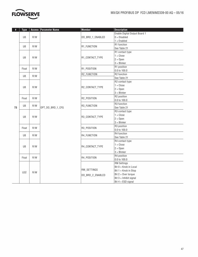
47
MX/QX PROFIBUS DP FCD LMENIM2339-00 AQ – 05/16
# Type Access Parameter Name Member Description
73
U8 R/W
OPT_DO_BRD_1_CFG
DO_BRD_1_ENABLEDEnable Digital Output Board 10 = Disabled1 = Enabled
U8 R/W R1_FUNCTIONR1 functionSee Table 21
U8 R/W R1_CONTACT_TYPE
R1 contact type1 = Close2 = Open3 = Blinker
Float R/W R1_POSITIONR1 position0.0 to 100.0
U8 R/WR2_FUNCTION R2 function
See Table 21
U8 R/W R2_CONTACT_TYPE
R2 contact type1 = Close2 = Open3 = Blinker
Float R/W R2_POSITIONR2 position0.0 to 100.0
U8 R/W R3_FUNCTIONR3 functionSee Table 21
U8 R/W R3_CONTACT_TYPE
R3 contact type1 = Close2 = Open3 = Blinker
Float R/W R3_POSITIONR3 position0.0 to 100.0
U8 R/W R4_FUNCTIONR4 functionSee Table 21
U8 R/W R4_CONTACT_TYPE
R4 contact type1 = Close2 = Open3 = Blinker
Float R/W R4_POSITIONR4 position0.0 to 100.0
U32 R/WRM_SETTINGS
DO_BRD_2_ENABLED
RM SettingsBit 0 = Knob in LocalBit 1 = Knob in StopBit 2 = Over torqueBit 3 = Inhibit signalBit 4 = ESD signal
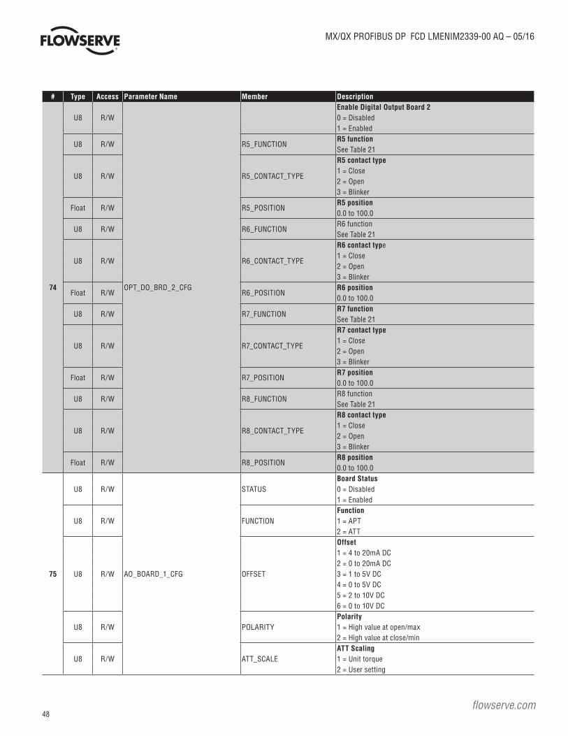
48
MX/QX PROFIBUS DP FCD LMENIM2339-00 AQ – 05/16
flowserve.com
# Type Access Parameter Name Member Description
74
U8 R/W
OPT_DO_BRD_2_CFG
Enable Digital Output Board 20 = Disabled1 = Enabled
U8 R/W R5_FUNCTIONR5 functionSee Table 21
U8 R/W R5_CONTACT_TYPE
R5 contact type1 = Close2 = Open3 = Blinker
Float R/W R5_POSITIONR5 position0.0 to 100.0
U8 R/W R6_FUNCTIONR6 functionSee Table 21
U8 R/W R6_CONTACT_TYPE
R6 contact type1 = Close2 = Open3 = Blinker
Float R/W R6_POSITIONR6 position0.0 to 100.0
U8 R/W R7_FUNCTIONR7 functionSee Table 21
U8 R/W R7_CONTACT_TYPE
R7 contact type1 = Close2 = Open3 = Blinker
Float R/W R7_POSITIONR7 position0.0 to 100.0
U8 R/W R8_FUNCTIONR8 functionSee Table 21
U8 R/W R8_CONTACT_TYPE
R8 contact type1 = Close2 = Open3 = Blinker
Float R/W R8_POSITIONR8 position0.0 to 100.0
75
U8 R/W
AO_BOARD_1_CFG
STATUSBoard Status0 = Disabled1 = Enabled
U8 R/W FUNCTIONFunction1 = APT2 = ATT
U8 R/W OFFSET
Offset1 = 4 to 20mA DC2 = 0 to 20mA DC3 = 1 to 5V DC4 = 0 to 5V DC5 = 2 to 10V DC6 = 0 to 10V DC
U8 R/W POLARITYPolarity1 = High value at open/max2 = High value at close/min
U8 R/W ATT_SCALEATT Scaling1 = Unit torque2 = User setting

49
MX/QX PROFIBUS DP FCD LMENIM2339-00 AQ – 05/16
# Type Access Parameter Name Member Description
76
U8 R/W
AO_BOARD_2_CFG
STATUSBoard Status0 = Disabled1 = Enabled
U8 R/W FUNCTIONFunction1 = APT2 = ATT
U8 R/W OFFSET
Offset1 = 4 to 20mA DC2 = 0 to 20mA DC3 = 1 to 5V DC4 = 0 to 5V DC5 = 2 to 10V DC6 = 0 to 10V DC
U8 R/W POLARITYPolarity1 = High value at open/max2 = High value at close/min
U8 R/W ATT_SCALEATT Scaling1 = Unit torque2 = User setting
77
U8 R/W
TWO_SPEED_TIMER_CLOSE_ CFG
STATUSTimer Status0 = Disabled1 = Enabled
Float R/W START_POSITIONStart Position0.0 to 100.0
Float R/W STOP_POSITIONStop Position0.0 to 100.0
Float R/W ON_TIMEOn Time1.0 to 20.0. Increments by 0.5
U8 R/W OFF_TIMEOff Time1 to 200. Increments by 1
78
U8 R/W
TWO_SPEED_TIMER_OPEN_ CFG
STATUSTimer Status0 = Disabled1 = Enabled
Float R/W START_POSITIONStart Position0.0 to 100.0
Float R/W STOP_POSITIONStop Position0.0 to 100.0
Float R/W ON_TIMEOn Time1.0 to 20.0. Increments by 0.5
U8 R/W OFF_TIMEOff Time1 to 200. Increments by 1
79
U8 R/W
DATE_AND_TIME
DAYDayRange: 1 to 31
U8 R/W MONTHMonthRange: 1 to 12
U16 R/W YEARYearRange: 0 to 65535
U8 R/W HOURHourRange: 0 to 23
U8 R/W MINUTESMinutesRange: 0 to 59
U8 R/W SECONDSSecondsRange: 0 to 59
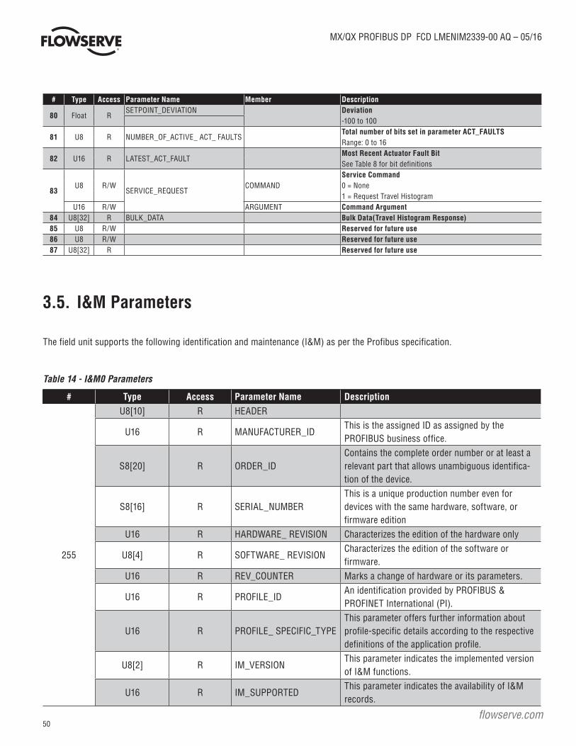
50
MX/QX PROFIBUS DP FCD LMENIM2339-00 AQ – 05/16
flowserve.com
# Type Access Parameter Name Member Description
80 Float RSETPOINT_DEVIATION Deviation
-100 to 100
81 U8 R NUMBER_OF_ACTIVE_ ACT_ FAULTSTotal number of bits set in parameter ACT_FAULTSRange: 0 to 16
82 U16 R LATEST_ACT_FAULTMost Recent Actuator Fault BitSee Table 8 for bit definitions
83U8 R/W
SERVICE_REQUESTCOMMAND
Service Command0 = None1 = Request Travel Histogram
U16 R/W ARGUMENT Command Argument84 U8[32] R BULK_DATA Bulk Data(Travel Histogram Response)85 U8 R/W Reserved for future use86 U8 R/W Reserved for future use87 U8[32] R Reserved for future use
3.5. I&M Parameters
The field unit supports the following identification and maintenance (I&M) as per the Profibus specification.
Table 14 - I&M0 Parameters
# Type Access Parameter Name Description
255
U8[10] R HEADER
U16 R MANUFACTURER_IDThis is the assigned ID as assigned by the PROFIBUS business office.
S8[20] R ORDER_IDContains the complete order number or at least a relevant part that allows unambiguous identifica-tion of the device.
S8[16] R SERIAL_NUMBERThis is a unique production number even for devices with the same hardware, software, or firmware edition
U16 R HARDWARE_ REVISION Characterizes the edition of the hardware only
U8[4] R SOFTWARE_ REVISIONCharacterizes the edition of the software or firmware.
U16 R REV_COUNTER Marks a change of hardware or its parameters.
U16 R PROFILE_IDAn identification provided by PROFIBUS & PROFINET International (PI).
U16 R PROFILE_ SPECIFIC_TYPEThis parameter offers further information about profile-specific details according to the respective definitions of the application profile.
U8[2] R IM_VERSIONThis parameter indicates the implemented version of I&M functions.
U16 R IM_SUPPORTEDThis parameter indicates the availability of I&M records.

51
MX/QX PROFIBUS DP FCD LMENIM2339-00 AQ – 05/16
3.6. NE107 Bit InformationTable 15 - NE107 Failure Bits
Bit Meaning0 Motor Over Temperature1 Over Torque2 Valve Jam3 Lost Phase4 Encoder Fault5 Contactor Fault6 Knob Fault7 Mainboard EEPROM Fault8 Mainboard Flash Memory Fault9 Mainboard RAM Fault10 Oil Temperature Too High (Arctic Units)11 MC Motor Volt Too Low12 MC Motor Volt Too High13 MC IRAM Fault14 MC IRAM Over Temperature15 MC Hall Critical16 MC Hall Limping17 MC Communication Loss18 MC Thermistor Communication Loss19 Monitor Relay Energized20 SPI To Mainboard Failure21 PROFIBUS DP Board Failure22 PROFIBUS DP Communication Loss Timeout23 PROFIBUS DP Channel-A Failure24 PROFIBUS DP Channel-B Failure25 MC Hardware Torque Over Limit26 MC Cop Fault
Table 16 - NE107 Function Check Bits
Bit Meaning0 Knob In Local1 Knob In Stop2 Open Torque Timer Expired3 Close Torque Timer Expired4 Manual Move5 Open Torque Switch6 Close Torque Switch7 Open Position Limit8 Close Position Limit9 Local ESD Active10 Network ESD Active11 Open Inhibit Active12 Close Inhibit Active13 PST Active14 PROFIBUS DP Channel-A Primary15 PROFIBUS DP Channel-B Primary
Table 17 - NE107 Out of Specification Bits
Bit Meaning0 Identical Limits1 Phase Reverse2 Line Voltage Too Low3 Line Frequency Too Low4 Mainboard mA Input Signal Lost5 Analog Board-1 mA Input Signal Lost6 Analog Board-2 mA Input Signal Lost7 Analog Board-1 mA Output Signal Lost8 Analog Board-2 mA Output Signal Lost
Table 18 - NE107 Maintenance Request Bits
Bit Meaning0 Encoder Warning1 Motor Temperature Warning2 Analog Board-1 Fault3 Analog Board-2 Fault4 Digital Output Board-1 Fault5 Digital Output Board-2 Fault

52
MX/QX PROFIBUS DP FCD LMENIM2339-00 AQ – 05/16
flowserve.com
3.7. Encoder Health Bits
Value Signal Remarks0x00000001 D102/Q102 Fault Wheel 00x00000002 Reserved always 0 (D101/Q101)0x00000004 Reserved always 0 (D130)0x00000008 D103/Q103 Fault Wheel 10x00000010 D104/Q104 Fault0x00000020 D105/Q105 Fault0x00000040 D106/Q106 Fault Wheel 20x00000080 D107/Q107 Fault0x00000100 D108/Q108 Fault0x00000200 D109/Q109 Fault Wheel 30x00000400 D110/Q110 Fault0x00000800 D111/Q111 Fault0x00001000 D112/Q112 Fault Wheel 40x00002000 D113/Q113 Fault0x00004000 D114/Q114 Fault0x00008000 D115/Q115 Fault Wheel 50x00010000 D116/Q116 Fault0x00020000 D117/Q117 Fault0x00040000 D118/Q118 Fault Wheel 60x00080000 D119/Q119 Fault0x00100000 D120/Q120 Fault0x00200000 D121/Q121 Fault Wheel 70x00400000 D122/Q122 Fault0x00800000 D123/Q123 Fault0x01000000 D124/Q124 Fault Wheel 80x02000000 D125/Q125 Fault0x04000000 D126/Q126 Fault0x08000000 D127/Q127 Fault Wheel 90x10000000 D128/Q128 Fault0x20000000 D129/Q129 Fault0x40000000 Reserved always 00x80000000 Reserved always 0
Value Signal Remarks0x00000001 D2/Q2 Fault Wheel 00x00000002 Reserved always 0 (D1/Q1)0x00000004 Reserved always 0 (Q130)0x00000008 D3/Q3 Fault Wheel 10x00000010 D4/Q4 Fault0x00000020 D5/Q5 Fault0x00000040 D6/Q6 Fault Wheel 20x00000080 D7/Q7 Fault0x00000100 D8/Q8 Fault0x00000200 D9/Q9 Fault Wheel 30x00000400 D10/Q10 Fault0x00000800 D11/Q11 Fault0x00001000 D12/Q12 Fault Wheel 40x00002000 D13/Q13 Fault0x00004000 D14/Q14 Fault0x00008000 D15/Q15 Fault Wheel 50x00010000 D16/Q16 Fault0x00020000 D17/Q17 Fault0x00040000 D18/Q18 Fault Wheel 60x00080000 D19/Q19 Fault0x00100000 D20/Q20 Fault0x00200000 D21/Q21 Fault Wheel 70x00400000 D22/Q22 Fault0x00800000 D23/Q23 Fault0x01000000 D24/Q24 Fault Wheel 80x02000000 D25/Q25 Fault0x04000000 D26/Q26 Fault0x08000000 D27/Q27 Fault Wheel 90x10000000 D28/Q28 Fault0x20000000 D29/Q29 Fault0x40000000 Reserved always 00x80000000 Reserved always 0
Table 20 - MX Encoder Health[1]Table 19 - MX Encoder Health[0]

53
MX/QX PROFIBUS DP FCD LMENIM2339-00 AQ – 05/16
3.8. Relay Control Functions
Table 21 - Relay control functions for S1, S2, and R1 to R8
Value Relay Control Function Remarks1 Closed2 Opened3 Position Trip if >= user position setting4 Closing Even when paused in 2-Speed5 Opening Even when paused in 2-Speed6 Stopped7 Moving Even when paused in 2-Speed8 Local selected Local control9 Motor over temperature10 Over torque11 Manual override12 Valve jammed13 Close torque switch14 Open torque switch15 Stop selected16 Lost phase17 ESD signal18 Close inhibit19 Open inhibit20 Analog input lost21 Remote selected22 LimiGard active23 Hardware failure24 CSE control25 Network controlled26 Standard PST Active27 Standard PST Passed28 Standard PST Failed Target29 Standard PST Failed Return30 Multi-Position 1 Custom input 4 and at M1 pos.31 Multi-Position 2 Custom input 4 and at M2 pos.32 Motor starts per hour exceeded33 At Home QX360 only34 At Port 1 QX360 only35 At Port 2 QX360 only36 At Port 3 QX360 only37 At Port 4 QX360 only38 At Port 5 QX360 only39 At Port 6 QX360 only40 At Port 7 QX360 only41 Network Communication Loss42 Local Operation43 Remote Operation

54
MX/QX PROFIBUS DP FCD LMENIM2339-00 AQ – 05/16
flowserve.com
4. Application NotesThese application notes are provided as a helpful guide only. Please verify the actual data with your site and follow all safety and procedural guidelines by Siemens and your organization when following these notes.
4.1. Mapping I/O Data from a Legacy DP Board
The following information may be useful for users who want to replace a legacy Profibus DP board (p/n 64-825-0046-4) with a new Profibus DP board (p/n 64-825-0212 or 64-825-0223).
Since the new Profibus DP board does not use various function blocks as described in the process automation profile, it is quite easy for the user to access device I/O data using the new DP board as described below:
Analog output function block of legacy DP board: The following analog output data can be written to the actuator using the parameter and module numbers as described in section 3.2:
Parameter ModuleSetpoint, Index 21. Module numbers 1, 2, 3, 4, 5, 6, 7, 8 and 9 provides access to this
writeable parameter.
Legacy DP board New DP board• Data type is a 32 bit floating point (4 bytes) and a quality
byte (1 byte). Total 5 bytes.• Data type is an unsigned 16 bit integer (2 bytes). Total 2
bytes.• Quality byte essential for operation. • Quality byte not applicable• Uses slot 1 with byte offset 0. • Uses index 21.
Discrete input function blocks of legacy DP board: The following discrete input data can be read from the actuator using the parameters and module numbers as described in section 3.2:
Parameter ModuleActuator Status (Table 7), Index 26. All 10 module numbers from 1 to 10 provides access to this read only parameter.Actuator Faults (Table 8), Index 27. All 10 module numbers from 1 to 10 provides access to this read only parameter.Actuator Indications (Table 9), Index 28. Module numbers 1, 5, 6, 7, 8, 9 and 10 provides access to this read only parameter.User IO (Table 10), Index 29. Module numbers 1, 4, 7, 8 and 10 provides access to this read only parameter.Network Status (Table 11), Index 30. All 10 module numbers from 1 to 10 provides access to this read only parameter.

55
MX/QX PROFIBUS DP FCD LMENIM2339-00 AQ – 05/16
Discrete output function blocks of legacy DP board: The following discrete output data can be written to actuator using the parameters and module numbers as described in section 3.2:
Parameter ModuleActuator Command, Index 22. Provides ability to send both type discrete output commands; close/stop/open and emer-gency shutdown commands to actuator.
Module numbers 1, 3, 4, 5, 7, 8, 9 and 10 provides access to this writeable parameter.
Relay Command, Index 23. Provides ability to send relay control commands to actuator.
Module number 1, 7 and 9 provides access to this writeable parameter.
Legacy DP board New DP board• Data type is an unsigned 8 bit integer (1 byte) and a
quality byte (1 byte). Total 2 bytes for each discrete output function block.
• Each parameter data type is an unsigned 16 bit integer (2 bytes each parameter).
• Quality byte not applicable.• Quality byte essential for operation.• Uses slot 6 and 7 with byte offset 0 in each slot.
• Discrete output information available via parameters with index numbers mentioned in above table.
Analog input function block of legacy DP board: The following analog input data can be read from actuator using the parameters and module numbers as described in section 3.2:
Parameter ModuleActuator Position, Index 24. Module numbers 1, 3, 4, 5, 6, 9 and 10 provides access to this
read only parameter.Actuator Torque, Index 25. Module numbers 1, 3, 4, 5, 6, 9 and 10 provides access to this
read only parameter.
Legacy DP board New DP board• Data type is a 32 bit floating point (4 bytes) and a quality
byte (1 byte). Total 5 bytes.• Each parameter data type is an unsigned 16 bit integer (2
bytes each parameter).• Quality byte essential for operation. • Quality byte not applicable.• Uses slot 8 with byte offset 0. • Analog input information available via parameters with index
numbers mentioned in above table.
Legacy DP board New DP board• Data type is an unsigned 8 bit integer (1 byte) and a quality
byte (1 byte). Total 2 bytes for each discrete input function block.• Each parameter data type is an unsigned 16 bit integer (2
bytes).• Quality byte essential for operation. • Quality byte not applicable.• Uses slot 2, 3, 4 and 5 with byte offset 0 in each slot. • Discrete input information available via parameters with index
numbers mentioned in above table.

56
MX/QX PROFIBUS DP FCD LMENIM2339-00 AQ – 05/16
flowserve.com
4.2. Siemens Step 7 SIMATIC ManagerFlowserve has tested the Profibus DP boards with Siemens Step 7 SIMATIC Manager, version 5.5, and noted the following aspects:
• Network profiles ‘DP’ and ‘Universal (DP/FMS)’ with default bus parameters worked with the Profibus DP boards.
4.3. Siemens S7 300 SystemsFlowserve has tested the Profibus DP (p/n 64-825-0223) and Profibus DP Redcom (p/n 64-825-0212) boards with the CPU315-2 DP (6ES7 315-2AH14-0AB0) and noted the following aspects:
• Non-redundant and simple Flying redundant modes worked. Full Flying and System redundancy modes were not supported.
• Switchover times for Flying redundancy (1 line and 2 line) occurred under 500ms.
4.4. Siemens S7 400 H SystemsFlowserve has tested the Profibus DP Redcom (p/n 64-825-0212) board with the CPU412-5 H PN/DP (6ES7 412-5HK06-0AB0) and noted the following aspects:
• System redundancy mode worked with switchover times under 500ms.
4.5. Control Parameter HierarchyIn several of the cyclic modules, both Setpoint and Actuator Command parameters are available. However, their application differs based on the operational modes of the actuator (position or open/close). The table below illustrates when these param-eters are interpreted or not.
Cyclic Module Parameters Operation when in Position Mode Operation when in Open/Close Mode
1Setpoint (Target) Accepted Ignored
Actuator Command ESD start/stop only Accepted
2Setpoint (Target) Accepted Ignored
Actuator Command N/A N/A
3Setpoint (Target) Accepted Ignored
Actuator Command ESD start/stop only Accepted
4Setpoint (Target) Accepted Ignored
Actuator Command ESD start/stop only Accepted
5Setpoint (Target) Accepted Ignored
Actuator Command ESD start/stop only Accepted
6Setpoint (Target) Accepted Ignored
Actuator Command N/A N/A
7Setpoint (Target) Accepted Ignored
Actuator Command ESD start/stop only Accepted
8Setpoint (Target) Accepted Ignored
Actuator Command ESD start/stop only Accepted
9Setpoint (Target) Accepted Ignored
Actuator Command ESD start/stop only Accepted
10Setpoint (Target) N/A N/A
Actuator Command ESD start/stop only Accepted

57
MX/QX PROFIBUS DP FCD LMENIM2339-00 AQ – 05/16
5. Frequently Asked Questions1. Can a legacy Profibus DP board (p/n 64-825-0046-4) be used together with a newer Profibus DP board (p/n 64-825-
0223) in the same unit? No. To achieve redundancy, a dual channel Profibus DP Redcom board (64-825-0212) must be used. The operations of
the legacy Profibus DP board and the new Profibus DP boards within the same unit will interfere with each other and may cause improper operation of the device.
2. Can two single channel Profibus DP boards (p/n 64-825-0223) be used instead of one Profibus DP Redcom dual channel board (p/n 64-825-0212) in the same unit?
No. The necessary internal Redstate communications only occur on the dual channel Profibus DP Redcom board (p/n 64-825-0212). If two single channel Profibus DP boards (p/n 64-825-0223) are installed, they will compete for the same internal resources and the unit will malfunction.
3. How can I tell which Profibus DP board is installed in the actuator? Refer to section 2.7.3 to use the knobs and the front panel LCD to determine which boards are installed.
4. What is the difference between the single channel and dual channel boards? Although the single channel (p/n 64-825-0223) board and the dual channel (p/n 64-825-0212) share the same printed
circuit board and firmware, the dual channel is populated with the extra electronic parts to form a redundant channel.
5. What is the difference between the single channel GSD file and the dual channel GSD file? The single channel GSD file and the dual channel GSD files are very similar with these notable differences: • The single channel GSD file will only allow configuration for one Profibus DP network. It does not allow for redundant
connections, switchover, or any of the redundancy modes. Options for redundancy modes have been removed to allow for easier configuration.
• The dual channel GSD file will work for both boards. However, any redundancy settings applied to a single channel board (p/n 64-825-0223) will not work and may cause network problems.
6. What is the difference between the simple and full Flying redundancy? In full Flying redundant mode, the Profibus DP Redcom board (p/n 64-825-0212) fully supports the Redstate diagnostic
extensions to the DPV1 protocol. In simple Flying redundant mode, these diagnostic extensions are not included in the communications and allows systems without diagnostic capability to operate without producing nuisance errors. Note that System redundancy requires full Redstate diagnostics.
7. What is the difference between the single-line and dual-line Flying redundant modes? Although the basic operation of Flying redundant mode is the same, the way the lines are terminated are different
when termination is enabled via the software options. In single-line mode, the software termination settings follow the primary and backup channel determination and will switch depending on which channel becomes primary. In dual-line (two-line) mode, the software termination settings are applied to channel A and B and do not switch based on which channel becomes primary.
8. How is the address set for the second channel? The channel address setting is done automatically. In Flying redundant mode, the backup address is the primary
address plus 64. For example, if the primary address is 7, the backup address is 71. Note that the address number follows the primary channel and not the physical channel (A or B). In System redundant mode, the backup channel address is the same as the primary channel address.

58
MX/QX PROFIBUS DP FCD LMENIM2339-00 AQ – 05/16
flowserve.com
6. GlossaryCommunications Protocol A standard for transferring data between intelligent devices, such as a Master Station, Distributed Control System, Programmable Logic Controller, or a computer.
DCS Distributed Control System: geographically distributed intelligent control devices communicating over a digital network (bus).
DP Decentralized Periphery: a PROFIBUS protocol used for high-speed transmission of user data; commonly used between a host station and distributed input/output devices at the field level.
Electronic Device Descriptions (EDD) A device-specific configuration file that provides a description of the configuration parameters in the MX/QX to the host engineering tool.
EIA Electronic Industries Association: an organized body of manufacturers that sets interface standards for the electrical and electronic industry. See RS-232C and RS-485.
Function Blocks A standard graphical representation of the control and measurement tasks that take place in the field devices, used for easy system configuration.
GSD File A device-specific configuration file that is used by the PROFIBUS Master to configure and communicate with the PROFIBUS device.
Host A computer, DCS, PLC or other microprocessor-based system that is in command of operations of the devices on its network.
9. When should I use the on-board termination? The on-board termination should be enabled when: • Only when the actuator is the last device on the Profibus network, and • When external terminal is not available or used. By default, on-board termination is disabled. Termination should only be used at the Profibus network endpoints.
10. What is a Partial Stroke Test (PST) and how do I initiate one? • A Partial Stroke Test (PST) moves the actuator, usually by a very small amount, to ensure correct operation of the
device and valve. This is typically needed for actuator/valves that have been idle for a long period of time. • To initiate a PST, first set the target position into the structure in parameter 54 (Table 13) and also set the 1 for the
command value. Send the parameter to the actuator and it will move to the target position and then return to the (previous) commanded position. The status and result can be obtained by reading parameter 55.
11. What version of the PDM is required? At the time of this writing, the firmware has been tested successfully with versions 6.1 and 8.1.
12. What version of the main board firmware is required? The new Profibus DP boards require mainboard firmware version 16Q03 or higher to operate. Earlier versions will not
recognize the new boards. This new mainboard firmware version is still backwards compatible with legacy Profibus DP boards.
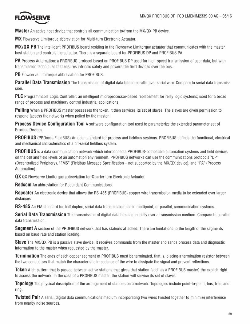
59
MX/QX PROFIBUS DP FCD LMENIM2339-00 AQ – 05/16
Master An active host device that controls all communication to/from the MX/QX PB device.
MX Flowserve Limitorque abbreviation for Multi-turn Electronic Actuator.
MX/QX PB The intelligent PROFIBUS board residing in the Flowserve Limitorque actuator that communicates with the master host station and controls the actuator. There is a separate board for PROFIBUS DP and PROFIBUS PA
PA Process Automation: a PROFIBUS protocol based on PROFIBUS DP used for high-speed transmission of user data, but with transmission techniques that ensures intrinsic safety and powers the field devices over the bus.
PB Flowserve Limitorque abbreviation for PROFIBUS.
Parallel Data Transmission The transmission of digital data bits in parallel over serial wire. Compare to serial data transmis-sion.
PLC Programmable Logic Controller: an intelligent microprocessor-based replacement for relay logic systems; used for a broad range of process and machinery control industrial applications.
Polling When a PROFIBUS master possesses the token, it then services its set of slaves. The slaves are given permission to respond (access the network) when polled by the master.
Process Device Configuration Tool A software configuration tool used to parameterize the extended parameter set of Process Devices.
PROFIBUS (PROcess FIeldBUS) An open standard for process and fieldbus systems. PROFIBUS defines the functional, electrical and mechanical characteristics of a bit-serial fieldbus system.
PROFIBUS is a data communication network which interconnects PROFIBUS-compatible automation systems and field devices on the cell and field levels of an automation environment. PROFIBUS networks can use the communications protocols “DP” (Decentralized Periphery), “FMS” (Fieldbus Message Specification – not supported by the MX/QX device), and “PA” (Process Automation).
QX QX Flowserve Limitorque abbreviation for Quarter-turn Electronic Actuator.
Redcom An abbreviation for Redundant Communications.
Repeater An electronic device that allows the RS-485 (PROFIBUS) copper wire transmission media to be extended over larger distances.
RS-485 An EIA standard for half duplex, serial data transmission use in multipoint, or parallel, communication systems.
Serial Data Transmission The transmission of digital data bits sequentially over a transmission medium. Compare to parallel data transmission.
Segment A section of the PROFIBUS network that has stations attached. There are limitations to the length of the segments based on baud rate and station loading.
Slave The MX/QX PB is a passive slave device. It receives commands from the master and sends process data and diagnostic information to the master when requested by the master.
Termination The ends of each copper segment of PROFIBUS must be terminated, that is, placing a termination resistor between the two conductors that match the characteristic impedance of the wire to dissipate the signal and prevent reflections.
Token A bit pattern that is passed between active stations that gives that station (such as a PROFIBUS master) the explicit right to access the network. In the case of a PROFIBUS master, the station will service its set of slaves.
Topology The physical description of the arrangement of stations on a network. Topologies include point-to-point, bus, tree, and ring.
Twisted Pair A serial, digital data communications medium incorporating two wires twisted together to minimize interference from nearby noise sources.

60
MX/QX PROFIBUS DP FCD LMENIM2339-00 AQ – 05/16
flowserve.com
Flowserve Corporation has established industry leadership in the design and manufacture of its products. When properly selected, this Flowserve product is designed to perform its intended function safely during its useful life. However, the purchaser or user of Flowserve products should be aware that Flowserve products might be used in numerous appli-cations under a wide variety of industrial service conditions. Although Flowserve can (and often does) provide general guidelines, it cannot provide specific data and warnings for all possible applications. The purchaser/user must therefore assume the ultimate responsibility for the proper sizing and selection, installation, operation, and maintenance of Flowser-ve products. The purchaser/user should read and understand the Installation Operation Maintenance (IOM) instructions included with the product, and train its employees and contractors in the safe use of Flowserve products in connection with the specific application.While the information and specifications contained in this literature are believed to be accurate, they are supplied for informative purposes only and should not be considered certified or as a guarantee of satisfactory results by reliance thereon. Nothing contained herein is to be construed as a warranty or guarantee, express or implied, regarding any matter with respect to this product. Because Flowserve is continually improving and upgrading its product design, the specifications, dimensions and information contained herein are subject to change without notice. Should any question arise concerning these provisions, the purchaser/user should contact Flowserve Corporation at any one of its worldwide operations or offices.© 2016 Flowserve Corporation, Irving, Texas, USA. Flowserve is a registered trademark of Flowserve Corporation.
FCD LMENIM2339-00 AQ - 05/16 Printed in USA.
To find your local Flowserve representative, visit www.flowserve.com/limitorque or call USA 1 800 225 6989
Flowserve CorporationFlow Control
United StatesFlowserve Limitorque5114 Woodall Road P.O. Box 11318Lynchburg, VA 24506-1318Phone: 434-528-4400Facsimile: 434-845-9736
EnglandFlowserve LimitorqueEuro HouseAbex RoadNewburyBerkshire, RG14 5EYUnited KingdomPhone: 44-1-635-46999Facsimile: 44-1-635-36034
JapanLimitorque – Nippon Gear Co., Ltd.NOF Bldg. 9th Floor1-11-11, Kita-Saiwai, Nishi-KuYokohama (220-0004)JapanPhone: 81-45-326-2065Facsimile: 81-45-320-5962
SingaporeFlowserve Limitorque12, Tuas Avenue 20Singapore 638824Phone: 65-6868-4628Facsimile: 65-6862-4940
ChinaLimitorque Beijing, Pte., Ltd.RM A1/A222/F, East Area, Hanwei PlazaNo. 7 Guanghua Road, Chaoyang DistrictBeijing 100004, Peoples Republic of ChinaPhone: 86-10-5921-0606Facsimile: 86-10-6561-2702
IndiaFlowserve Limitorque, Ltd. Plot No 4 Export Promotional Industrial ParkWhitefield, Bangalore 560066 IndiaPhone: 91-80-40146200Facsimile: 91-80-28410286