user instructions - flowserve · 9 wiring and grounding ... particular dangers and/or to provide...
TRANSCRIPT
1
StarPac Intelligent Control System FCD VLENIM0066-05 04/14
flowserve.com
®
Experience In Motion
USER INSTRUCTIONSInstallation
OperationMaintenance
StarPac 3Intelligent Control SystemFCD VLENIM0066-05 04/14


Table of Contents
1 General Information .................................................................................... 5
1.1 Using ............................................................................................... 5
1.2 Applicability ..................................................................................... 5
1.3 Terms Concerning Safety ................................................................ 5
1.4 Personal Protective Equipment........................................................ 5
1.5 Qualified Personnel ......................................................................... 6
1.6 Spare Parts ...................................................................................... 6
1.7 Service / Repair ............................................................................... 6
1.8 Storage ............................................................................................ 6
2 Unpacking .................................................................................................. 8
3 Installation .................................................................................................. 8
4 Quick-Check ............................................................................................... 9
5 Valve Maintenance ...................................................................................... 9
6 Valve Disassembly and Inspection .............................................................. 10
7 StarPac 3 Operation .................................................................................... 11
7.1 Overview ......................................................................................... 11
7.2 Specifications .................................................................................. 11
7.3 Positioner Operation ........................................................................ 13
8 Mounting and Installation ........................................................................... 14
8.1 Mounting to Flowserve Valtek Linear Mark One Valves ................... 14
8.2 Mounting to Standard Flowserve Valtek Rotary Valves.................... 14
8.3 Optional Flowserve Valtek Rotary Mounting Procedure ................... 17
8.4 Tubing Positioner to Actuator .......................................................... 18
9 Wiring and Grounding Guidelines ............................................................... 19
9.1 Shielding Versus Grounding ............................................................ 20
9.2 Grounding Screw............................................................................. 20
9.3 24 VDC Power ................................................................................. 20
9.4 RS-485 Communications ................................................................ 20
9.5 4-20 mA Command Input, Auxiliary Input and Feedback Output ............... 20
9.6 Discrete Inputs and Outputs ............................................................ 20
9.7 RS-232 to RS-485 Converter Connection ........................................ 20
10 Wiring the StarPac 3 System ...................................................................... 21
10.1 General ............................................................................................ 21
10.2 Wiring Connections ......................................................................... 21
10.3 Setting the Jumpers ........................................................................ 23
StarPac Intelligent Control System FCD VLENIM0066-05 04/14
4
®
11 RS-485 Communication Configurations ..................................................... 24
11.1 System Communication Default Configuration ................................ 24
11.2 Selecting Correct Address Setting ................................................... 24
11.3 Selecting Correct Baud Rate Setting ................................................ 24
11.4 Selecting Correct Modbus Transmission Mode ............................... 25
11.5 Selecting Proper RS-485 Termination Resistor Setting ................... 25
11.6 Communication Port B .................................................................... 25
12 StarPac 3 Calibration .................................................................................. 26
13 StarPac 3 Configuration .............................................................................. 26
14 System Maintenance .................................................................................. 26
14.1 Overview ......................................................................................... 26
14.2 Mechanical Subsystem Maintenance ............................................... 26
14.3 Position Feedback System ............................................................... 27
14.4 Pressure Sensor Replacement ........................................................ 27
14.5 Pressure Sensor Cable Replacement ............................................... 29
14.6 Thermocouple Replacement ............................................................ 30
14.7 Keypad Assembly Replacement ....................................................... 31
14.8 Driver Module Assembly Replacement ............................................ 31
14.9 Regulator Replacement ................................................................... 35
14.10 Checking or Setting Internal Regulator Pressure .............................. 35
14.11 Checking or Setting the Driver Module Minimum Pressure ............. 37
14.12 Spool Valve Cover Replacement ....................................................... 39
14.13 Spool Valve Replacement ................................................................. 39
14.14 Stem Position Sensor Replacement ................................................. 40
14.15 Main PCB Assembly Replacement .................................................... 41
14.16 Customer Interface Board Replacement ........................................... 43
15 Optional Vented Design .............................................................................. 44
16 Parts List .................................................................................................... 46
17 StarPac 3 Spare Parts Kits .......................................................................... 48
18 StarPac 3 Mounting Kits ............................................................................. 49
19 Pressure Sensor Part Numbers .................................................................. 49
20 Pressure Sensor Spare Parts Kits ............................................................... 50
21 Temperature Sensor Spare Parts Kits ......................................................... 53
22 StarPac 3 Stainless Steel Tubing Kits ......................................................... 54
23 StarPac 3 System Troubleshooting ............................................................. 55
24 StarPac 3 Pressure Sensor Troubleshooting .............................................. 56
25 StarPac 3 Electronics Initialization Procedure ............................................ 57
26 How to Order .............................................................................................. 59
5
StarPac Intelligent Control System FCD VLENIM0066-05 04/14
flowserve.com
®
1 General Information
1.1 Using
The following instructions are designed to assist in unpacking, installing and performing maintenance as required on
Flowserve products. Product users and maintenance personnel should thoroughly review this bulletin prior to unpa-
cking, installing, operating, or performing any maintenance. In most cases, Flowserve valves, actuators and accessories
are designed for specific applications (e.g. with regard to medium, pressure, and temperature). For this reason, they
should not be used in other applications without first contacting the manufacturer. The product Installation, Operation,
and Maintenance Instructions provides important additional safety information.
1.2 Applicability
The following instructions are applicable to the maintenance and installation of Flowserve control valves with the StarPac
3 control system. These instructions cannot claim to cover all details of all possible product variations, nor can they pro-
vide information for every possible example of installation, operation or maintenance. This means that the instructions
normally include only the directions to be followed by qualified personal using the product for its defined purpose. If
there are any uncertainties in this respect, particularly in the event of missing product-related information, clarification
must be obtained via the appropriate Flowserve sales office. All Flowserve User Instruction Manuals are available at www.
flowserve.com.
1.3 Terms Concerning Safety
The safety terms DANGER, WARNING, CAUTION and NOTE are used in these instructions to highlight
particular dangers and/or to provide additional information on aspects that may not be readily apparent.
DANGER: Indicates that death, severe personal injury and/or substantial property damage will occur if proper
precautions are not taken.
WARNING: Indicates that death, severe personal injury and/or substantial property damage can occur if proper
precautions are not taken.
CAUTION: Indicates that minor personal injury and/or property damage can occur if proper precautions are not
taken.
NOTE: Indicates and provides additional technical information, which may not be obvious, even to qualified
personnel. Compliance with other notes, which may not be particularly emphasized, with regard to transport,
assembly, operation and maintenance and with regard to technical documentation (e.g. in the operating instruc-
tions, product documentation, or on the product itself) is essential, in order to avoid faults, which can directly or
indirectly cause severe personal injury or property damage.
1.4 Personal Protective Equipment
Flowserve products are often used in problematic applications (e.g. under extremely high pressures with dangerous,
toxic or corrosive mediums). When performing service, an inspection or repair operation always ensure that the valve
and actuator are depressurized and that the valve has been cleaned and is free from harmful substances. In such cases,
pay particular attention to personal protection (e.g. protective clothing, gloves, glasses etc.).
STOP!
StarPac Intelligent Control System FCD VLENIM0066-05 04/14
6
®
1.5 Qualified Personnel
Qualified personnel are people who, on account of their training, experience and instruction and their knowledge of
relevant standards, specifications, accident prevention regulations and operating conditions, have been authorized by
those responsible for the safety of the plant to perform the necessary work and who can recognize and avoid possible
dangers.
1.6 Spare Parts
Use only Flowserve original spare parts. Flowserve cannot accept responsibility for any damages that occur from using
spare parts or fastening materials from other manufactures. If Flowserve products (especially sealing materials) have
been on store for long periods of time check them for corrosion or deterioration before putting them into use. See pages
46-54 for parts listings and numbers
1.7 Service / Repair
To avoid possible injury to personnel or damage to products, safety terms must be strictly adhered to. Modifying this
product, substituting non-factory parts, or using maintenance procedures other than those outlined in these Installation,
Operation, and Maintenance Instructions could drastically affect performance, be hazardous to personnel and equip-
ment, and may void existing warranties. Between the actuator and the valve there are moving parts. To avoid injury,
Flowserve provides pinch-point-protection in the form of cover plates, especially where side-mounted positioners are
fitted. If these plates are removed for inspection, service or repair special attention is required. After completing work the
cover plates must be refitted. Apart from the operating instructions and the obligatory accident prevention directives valid
in the country of use, all recognized regulations for safety and good engineering practices must be followed.
WARNING: Before products are returned to Flowserve for repair or service, Flowserve must be provided with a
certificate that confirms that the product has been decontaminated and is clean. Flowserve will not accept deliveries if a
certificate has not been provided (a form can be obtained from Flowserve).
1.8 StorageIn most cases, Flowserve products are manufactured from stainless steel. Products not manufactured from stainless
steel are provided with an epoxy resin coating. This means that Flowserve products are well protected from corrosion.
Nevertheless, Flowserve products must be stored adequately in a clean, dry environment. Heating is not required. Con-
trol valve packages must be stored on suitable skids, not directly on the floor. Plastic caps are fitted to protect the flange
faces and prevent the ingress of foreign materials. These caps should not be removed until the valve is actually mounted
into the system.
Long Term Storage of StarPac 3 Positioner in Humid Locations
The StarPac 3 positioners are designed to operate in humid environments when connected to a proper instrument air
supply. There are some occasions when valves and positioners are stored at job sites or installed and commissioned
and then left without instrument air for months. To make startup easier for units that are left without instrument air and
insure that the positioners will be ready to operate, it is recommended that the vent assembly of the positioner be sealed
preferably with a desiccant pouch sealed with the vent assembly.
STOP!
7
StarPac Intelligent Control System FCD VLENIM0066-05 04/14
flowserve.com
®
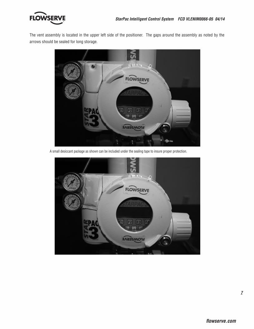
The vent assembly is located in the upper left side of the positioner. The gaps around the assembly as noted by the
arrows should be sealed for long storage.
Joints to be sealed
A small desiccant package as shown can be included under the sealing tape to insure proper protection.
StarPac Intelligent Control System FCD VLENIM0066-05 04/14
8
®
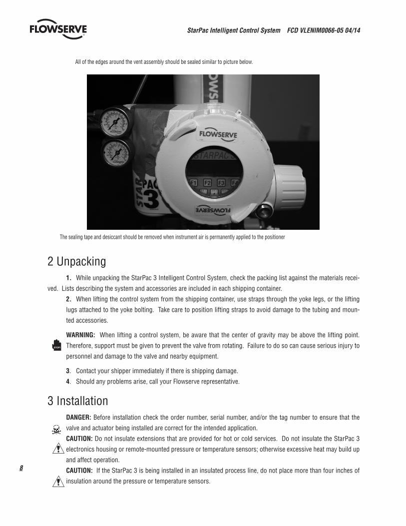
The sealing tape and desiccant should be removed when instrument air is permanently applied to the positioner
All of the edges around the vent assembly should be sealed similar to picture below.
Desiccant packet
Removable sealing tape
2 Unpacking 1. While unpacking the StarPac 3 Intelligent Control System, check the packing list against the materials recei-
ved. Lists describing the system and accessories are included in each shipping container.
2. When lifting the control system from the shipping container, use straps through the yoke legs, or the lifting
lugs attached to the yoke bolting. Take care to position lifting straps to avoid damage to the tubing and moun-
ted accessories.
WARNING: When lifting a control system, be aware that the center of gravity may be above the lifting point.
Therefore, support must be given to prevent the valve from rotating. Failure to do so can cause serious injury to
personnel and damage to the valve and nearby equipment.
3. Contact your shipper immediately if there is shipping damage.
4. Should any problems arise, call your Flowserve representative.
3 Installation DANGER: Before installation check the order number, serial number, and/or the tag number to ensure that the
valve and actuator being installed are correct for the intended application.
CAUTION: Do not insulate extensions that are provided for hot or cold services. Do not insulate the StarPac 3
electronics housing or remote-mounted pressure or temperature sensors; otherwise excessive heat may build up
and affect operation.
CAUTION: If the StarPac 3 is being installed in an insulated process line, do not place more than four inches of
insulation around the pressure or temperature sensors.
STOP!
9
StarPac Intelligent Control System FCD VLENIM0066-05 04/14
flowserve.com
®
CAUTION: On valves equipped with air filters, the air filter must point down to perform properly.
NOTE: In some rare cases, the air supply must be limited to less than 150 psi (10.3 bar). This is indicated on a
sticker found near the upper air port on the actuator cylinder. An air regulator should be installed to ensure the
supply pressure does not exceed the line pressure indicated on the sticker.
1. Pipelines must be correctly aligned to ensure that the valve is not fitted under tension.
2. Fire protection must be provided by the user.
3. Before installing the valve, clean the line of dirt, welding chips, scale and other foreign material.
4. Whenever possible, the valve should be installed in an upright position. Vertical installation permits easier
valve maintenance.
5. Be sure to provide proper overhead clearance for the actuator to allow for disassembly of the plug from the
valve body. Refer to the appropriate actuator User Instructions for proper clearances. Actuator User Instructions
are available at www.flowserve.com.
6. Double-check flow direction to be sure the valve is installed correctly. Flow direction is indicated by the arrow
attached to the body.
7. If welding the valve into the line, use extreme care to avoid excess heat build up in the valve.
8. Connect the air supply and instrument signal lines.
4 Quick-checkPrior to start-up, check the control valve by following these steps:
1. Stroke the valve and observe the plug position indicator on the stem clamp compared to the stroke indicator
plate. The plug should change position in a smooth, linear fashion.
NOTE: Due to excessive friction, graphite packing can cause the plug stem to move in a jerky fashion.
2. Check for full stroke by making appropriate instrument signal changes.
3. Check all air connections for leaks.
4. Check packing box bolting for the correct adjustment. Refer to the packing installation manual for specific
details on maintaining the style of packing supplied.
CAUTION: Do not over-tighten packing. This can cause excessive packing wear and high stem friction that may
impede plug movement.
5. Make sure the valve fails in the correct direction in case of air failure. This is done by turning off the air supply
and observing the failure direction.
6. After a temperature excursion has occurred, bonnet flange bolting should be re-torqued to ensure bonnet
seals do not leak.
5 Valve MaintenanceAt least once every six months, check for proper operation by following the preventative maintenance steps outlined
below. These steps can be performed while the valve is in-line and, in some cases, without interrupting service. If an
internal problem is suspected, refer to the Valve Disassembly and Inspection in the Installation, Operation and Mainte-
nance (IOM) instructions of the valve that the StarPac 3 system is mounted to.

StarPac Intelligent Control System FCD VLENIM0066-05 04/14
10
®
1. Look for signs of gasket leakage through the end flanges and bonnet. Re-torque flange and bonnet bolting (if
required).
2. Examine the valve for damage caused by corrosive fumes or process drippings.
3. Clean valve and repaint areas of severe oxidation.
4. Check packing box bolting for proper tightness. Refer to the Installation, Operation and Maintenance (IOM)
instructions for the valve for specific details on maintaining the style of packing supplied.
CAUTION: Do not over-tighten packing. This can cause excessive packing wear and high stem friction that may
impede stem movement.
5. If possible, stroke the valve and check for smooth, full-stroke operation. Unsteady stem movement could
indicate an internal valve problem.
NOTE: Due to excessive friction, graphite packing can cause the plug stem to move in a jerky fashion.
WARNING: Keep hands, hair and clothing away from all moving parts when operating the valve. Failure to do so
can cause serious injury.
6. Make sure positioner linkage and stem clamp are securely fastened. If the stem clamp is loose, check plug
thread engagement (refer to the “Reassembly and Installation” section for the correct procedure on aligning the
plug with the seat). Tighten stem clamp nut.
7. Ensure all accessories, bolting and brackets are securely fastened.
8. If possible, remove air supply and observe actuator for correct fail-safe action.
9. Check rubber actuator bellows for splits, cuts or wear.
10. Spray a soap solution around the actuator cylinder retaining ring and actuator stem guide to check for air leaks
through the O-rings.
11. Clean any dirt and other foreign material from the plug stem.
12. If an air filter is supplied, check and replace cartridge if necessary.
6 Valve Disassembly and InspectionThe StarPac 3 Control Intelligent Control System can be mounted to a variety of different control valves. To disassemble
and inspect the control valve that the StarPac 3 is mounted to, refer to the Installation, Operation and Maintenance (IOM)
instructions for that particular valve (i.e. Mark One, Mark 100, ShearStream or MaxFlo 3). Refer to section 14 of this
manual for instructions on how to remove the pressure sensor cables and thermocouple prior to valve disassembly.
7 StarPac 3 Operation7.1 Overview
The StarPac 3 is double-acting, capable of supplying air to either side of the actuator piston while exhausting
the other side to the atmosphere. Also, the positioner can be mounted on either Flowserve Valtek linear or rotary
actuators without modification to the actuator.
Since the positioner is insensitive to supply pressure changes and can handle supply pressures from 30 to 150
psig, a supply regulator is usually not required; however, an air filter is required due to the close tolerances of the
spool assembly.
STOP!
11
StarPac Intelligent Control System FCD VLENIM0066-05 04/14
flowserve.com
®
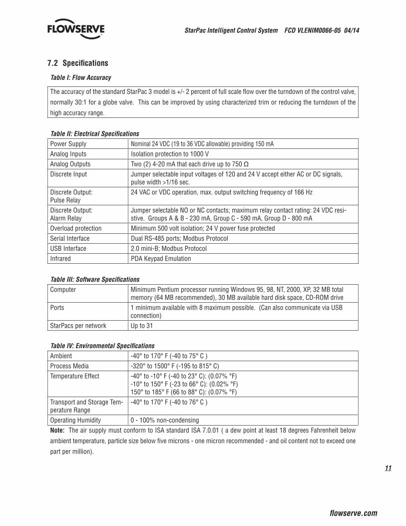
7.2 Specifications
Table I: Flow Accuracy
The accuracy of the standard StarPac 3 model is +/- 2 percent of full scale flow over the turndown of the control valve,
normally 30:1 for a globe valve. This can be improved by using characterized trim or reducing the turndown of the
high accuracy range.
Table II: Electrical SpecificationsPower Supply Nominal 24 VDC (19 to 36 VDC allowable) providing 150 mAAnalog Inputs Isolation protection to 1000 VAnalog Outputs Two (2) 4-20 mA that each drive up to 750 ΩDiscrete Input Jumper selectable input voltages of 120 and 24 V accept either AC or DC signals,
pulse width >1/16 sec.Discrete Output: Pulse Relay
24 VAC or VDC operation, max. output switching frequency of 166 Hz
Discrete Output: Alarm Relay
Jumper selectable NO or NC contacts; maximum relay contact rating: 24 VDC resi-stive. Groups A & B - 230 mA, Group C - 590 mA, Group D - 800 mA
Overload protection Minimum 500 volt isolation; 24 V power fuse protectedSerial Interface Dual RS-485 ports; Modbus ProtocolUSB Interface 2.0 mini-B; Modbus ProtocolInfrared PDA Keypad Emulation
Table III: Software SpecificationsComputer Minimum Pentium processor running Windows 95, 98, NT, 2000, XP, 32 MB total
memory (64 MB recommended), 30 MB available hard disk space, CD-ROM drivePorts 1 minimum available with 8 maximum possible. (Can also communicate via USB
connection)StarPacs per network Up to 31
Table IV: Environmental SpecificationsAmbient -40° to 170° F (-40 to 75° C )Process Media -320° to 1500° F (-195 to 815° C)Temperature Effect -40° to -10° F (-40 to 23° C): (0.07% °F)
-10° to 150° F (-23 to 66° C): (0.02% °F)150° to 185° F (66 to 88° C): (0.07% °F)
Transport and Storage Tem-perature Range
-40° to 170° F (-40 to 76° C )
Operating Humidity 0 - 100% non-condensingNote: The air supply must conform to ISA standard ISA 7.0.01 ( a dew point at least 18 degrees Fahrenheit below
ambient temperature, particle size below five microns - one micron recommended - and oil content not to exceed one
part per million).
StarPac Intelligent Control System FCD VLENIM0066-05 04/14
12
®
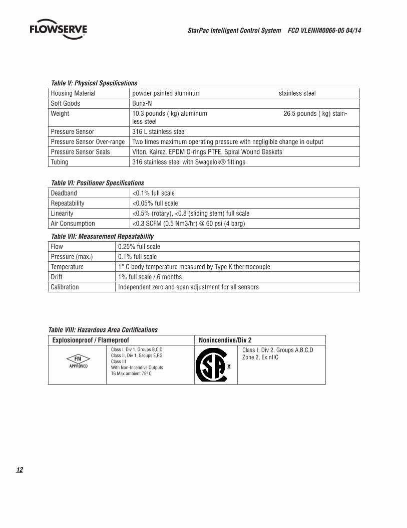
Table V: Physical SpecificationsHousing Material powder painted aluminum stainless steelSoft Goods Buna-NWeight 10.3 pounds ( kg) aluminum 26.5 pounds ( kg) stain-
less steelPressure Sensor 316 L stainless steelPressure Sensor Over-range Two times maximum operating pressure with negligible change in outputPressure Sensor Seals Viton, Kalrez, EPDM O-rings PTFE, Spiral Wound GasketsTubing 316 stainless steel with Swagelok® fittings
Table VI: Positioner SpecificationsDeadband <0.1% full scaleRepeatability <0.05% full scaleLinearity <0.5% (rotary), <0.8 (sliding stem) full scaleAir Consumption <0.3 SCFM (0.5 Nm3/hr) @ 60 psi (4 barg)
Table VII: Measurement RepeatabilityFlow 0.25% full scalePressure (max.) 0.1% full scaleTemperature 1° C body temperature measured by Type K thermocoupleDrift 1% full scale / 6 monthsCalibration Independent zero and span adjustment for all sensors
Table VIII: Hazardous Area Certifications Explosionproof / Flameproof Nonincendive/Div 2
Class I, Div 1, Groups B,C,DClass II, Div 1, Groups E,F,G Class III With Non-Incendive Outputs T6 Max ambient 750 C
Class I, Div 2, Groups A,B,C,D Zone 2, Ex nIICFM
APPROVED

13
StarPac Intelligent Control System FCD VLENIM0066-05 04/14
flowserve.com
®
7.3 Positioner OperationFigure 1: StarPac 3 Positioner Schematic (air-to-open configuration)
The StarPac 3 Positioner is an electric feedback instrument. Figure 1 shows a StarPac 3 installed on a double-acting
actuator for air-to-open action. Positioning is based on a balance of two signals: one proportional to the modulator input
signal and the other proportional to the stem position.
The supply pressure for the positioner modulator is tapped off the main supply and is filtered as it passes through a field-
replaceable, coalescing filter element in the module. Next it passes through an internal pressure regulator that regulates
it to approximately 21.5 psig. The air then goes through an orifice that restricts the flow and air consumption (refer to
Figure 1).
The air is further controlled to 6-12 psig using a spring-diaphragm flapper that is attracted by an electromagnet to a noz-
zle. A temperature compensated Hall Effect sensor mounted on a circuit board senses the spool valve position. The Hall
Effect sensor and circuitry create a feedback loop, which determines how much current to send to the electromagnet for
a desired spool valve position. The electromagnet in the feedback loop varies the nozzle-flapper spacing, which regulates
the output pressure to 6-12 psig proportional to the command input signal.
When these opposing signals are equal, the system will be in equilibrium and the stem will be in the position called for
by the command signal. If these opposing signals are not equal, the spool valve will move up (or down) and, by means
of the modulator, will change the output pressures and flow rate. This will cause the piston to move until the signal of the
feedback sensor equalizes with the command signal.
The detailed sequence of positioner operations are as follows: An increase in the command signal forces the modulator
signal capsule and spool valve upward. This motion of the modulator also pushes the pilot valve spool upward from its
equilibrium position. This opens the pilot valve ports, supplying air to port one and exhausting air from port two. This
OO
Electromagnetic Coil
Nozzle FlapperDigital PositionAlgorithm
Spool Valve
Flame Arrestors
Pressure Sensor
Air Supply
Orifice
ExhaustOUTPUT 1
OUTPUT 2
Exhaust
FlameArrestor
Air-to-OpenConfiguration
Flame Arrestor
Filter
RegulatorHall EffectSensor
StemPositionSensor
StarPac Intelligent Control System FCD VLENIM0066-05 04/14
14
®
causes the actuator piston to move upward.
This upward motion of the piston is transmitted back to the positioner through the feedback linkage and position feed-
back potentiometer signal changing proportionally to the valve position. The piston continues to stroke upward until the
signal of the feedback sensor increases sufficiently to counter the signal being sent to the modulator. At this point, the
spool is at its equilibrium position as the pressures in the cylinder stabilize and the air flow to the actuator decreases.
After the piston has reached the required position, the feedback signal will equal the spool position generated in the mo-
dulator capsule. The computer will then make small null adjustments to fine-tune the desired position and compensate
for changes in dynamic loading.
A decrease in the command signal reverses the described actions causing a proportional downward movement of the
actuator piston and stem.
8 Mounting and Installation
8.1 Mounting to Flowserve Valtek Linear Mark One Valves
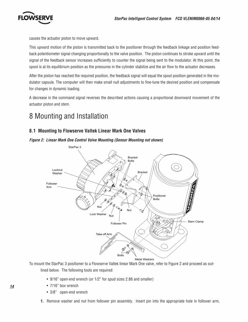
Figure 2: Linear Mark One Control Valve Mounting (Sensor Mounting not shown)
To mount the StarPac 3 positioner to a Flowserve Valtek linear Mark One valve, refer to Figure 2 and proceed as out-
lined below. The following tools are required:
• 9/16” open-end wrench (or 1/2” for spud sizes 2.88 and smaller)
• 7/16” box wrench
• 3/8” open-end wrench
1. Remove washer and nut from follower pin assembly. Insert pin into the appropriate hole in follower arm,
StarPac 3
LocknutWasher
FollowerArm
BracketBolts
Bracket
PositionerBolts
Stem Clamp
Metal WashersBolts
Take-off Arm
Follower Pin
NutLock Washer
NutNut
15
StarPac Intelligent Control System FCD VLENIM0066-05 04/14
flowserve.com
®
based on stroke length. The stroke lengths are stamped next to their corresponding holes in the follower
arms. Make sure the unthreaded end of the pin is on the stamped side of the arm. Re-install lock washer and
tighten nut to complete follower arm assembly.
2. Slide double-D slot in the follower arm assembly over the flats on the position feedback shaft in the back of
the positioner. Make sure the arm is pointing toward the customer interface side of the positioner. Slide lock
washer over the threads on the shaft and tighten down the nut.
3. Line up the mounting bracket with the mounting holes on the actuator yoke. Bolt the mounting bracket on to
actuator yoke.
4. Align the three outer mounting holes on the positioner with the three positioner mounting holes on the bra-
cket. Fasten with 1/4-20 x1/2” bolts.
5. Position the take-off arm mounting slot against the stem clamp mounting pad. Apply Loctite 222 to the take-
off arm bolting and in and insert through washers into the stem clamp. Leave bolts loose.
6. Slide the appropriate pin slot of the take-off arm, based on stroke length, over the follower arm pin. The
appropriate stroke lengths are stamped by each pin slot.
7. Center the take-off arm on the rolling sleeve of the follower pin.
8. Align the take-off arm with the top plane of the stem clamp and tighten bolting. Torque to 120 in-lb.
NOTE: If mounted properly, the follower arm should be horizontal when the valve is at 50% stroke and should
move approximately ±30° from horizontal over the full stroke of the valve. If mounted incorrectly, a stroke ca-
libration error will occur. Reposition the feedback linkage or rotate the position sensor to correct the error.
8.2 Mounting to Standard Flowserve Valtek Rotary Valves
The standard rotary mounting applies to Flowserve Valtek valve/actuator assemblies that do not have mounted volume
tanks or handwheels. The standard mounting uses a linkage directly coupled to the valve shaft. This linkage has been
designed to allow for minimal misalignment between the positioner and the actuator. The tools required for the following
procedure are:
• 5/32” Allen wrench
• 1/2” open-end wrench
• 3/8” socket with extension
• 3/16” nutdriver

StarPac Intelligent Control System FCD VLENIM0066-05 04/14
16
®
1. Fasten the splined lever adapter to the splined lever using two #4-40 x 1/2” self-tapping screws.
2. Slide the take-off arm assembly onto the splined lever adapter shaft. Insert the screw with star washer
through the take off arm and add the second star washer and nut. Tighten nut with socket so arm is lightly
snug on the shaft but still able to rotate. This will be tightened after linkage is correctly oriented.
3. Attach follower arm to positioner feedback shaft using the star washer and 10-32 nut.
NOTE: The arm will point up when feedback shaft is in the free position.
4. Using four 5/16”-18 x 5/8” bolts, fasten positioner to universal bracket using appropriate hole pattern (stam-
ped on bracket).
5. Using a 1/2” end wrench and two 5/16”-18 x 1/2” bolts, attach bracket to actuator transfer case pad. Leave
these bolts slightly loose until final adjustments are made.
6. Rotate take-off arm so the follower pin will slide into the slot on the take-off arm. Adjust the bracket position
as needed noting the engagement of the follower pin and the take-off arm slot. The pin should extend appro-
ximately 1/16” past the take-off arm. When properly adjusted, securely tighten the bracketing bolts.
7. Tube the StarPac 3 positioner to the actuator according to the instructions given in Section 8.4, “Tubing Posi-
tioner to Actuator.”
8. With supply pressure off, rotate the follower arm in the same direction the shaft would rotate upon a loss of
Figure 3: Standard Rotary Mounting (Sensor Mounting not shown)
StarPac 3
Follower Arm
*Located in appropriatehole pattern as indicated onbracket. (25, 50, 100/200)
Positioner Bolts 5/16-18 (4)*
Bracket Bolts 5/16-18 (2, not shown)
Take-off Arm, RotaryLock Washer (2)10-32 Bolt10-32 Nut
Self-tapping Screws (2)
Spline Lever Adapter
10-32 NutLock Washer
17
StarPac Intelligent Control System FCD VLENIM0066-05 04/14
flowserve.com
®
supply pressure. When the mechanical stop of the follower arm (positioner) is reached, rotate back approxi-
mately 15 degrees.
9. Hold the take-off arm in place; tighten the take-off arm screw.
NOTE: The take-off arm should be snug enough to hold the follower arm in place
but allow movement when pushed.
10. Connect regulated air supply to appropriate port in manifold.
11. Remove main cover and perform a stroke calibration using the key pad (refer to the StarPac 3 User Interface
Manual. Make sure the StarPac 3 has been configured with the proper air action.
12. If the calibration was successful, continue with step 9. If the calibration failed, the A/D feedback values were
exceeded and the arm must be adjusted away from the positioners limits. Return to step 2 and rotate the arm
back approximately 10 degrees.
NOTE: Remember to remove the air supply before re-adjusting take-off arm.
13. Tighten the nut on the take-off arm. The socket head screw of the take-off arm must be tight, about 40 in-
lb.
NOTE: If the take-off arm slips, the positioner must be recalibrated.
WARNING: Failure to follow the procedure will result in positioner and/or linkage damage. Check air-action and
stroke carefully before lockdown of take-off arm to splined lever adapter.
8.3 Optional Flowserve Valtek Rotary Mounting Procedure
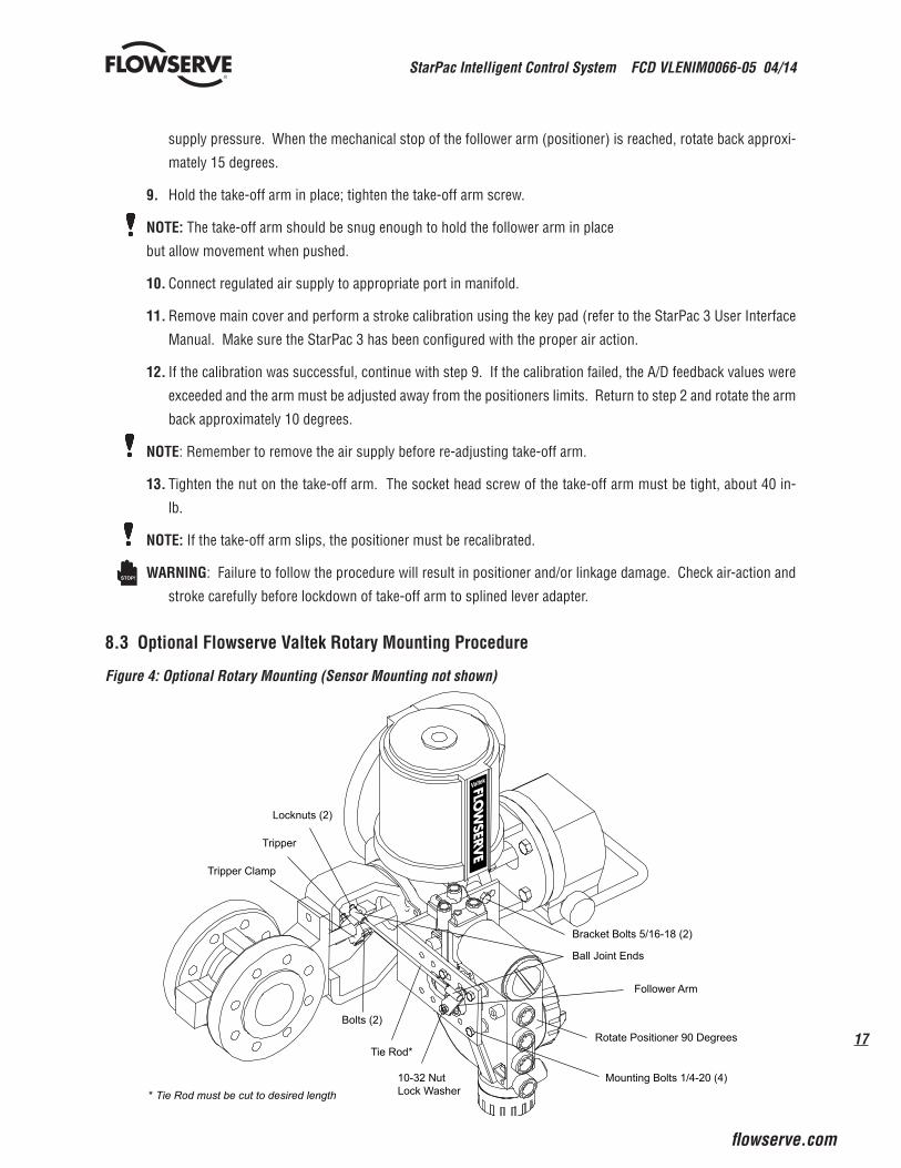
Figure 4: Optional Rotary Mounting (Sensor Mounting not shown)
STOP!
Bracket Bolts 5/16-18 (2)
Ball Joint Ends
Follower Arm
Rotate Positioner 90 Degrees
Mounting Bolts 1/4-20 (4)
Locknuts (2)
Tripper
Tripper Clamp
Bolts (2)
Tie Rod*
10-32 NutLock Washer* Tie Rod must be cut to desired length

StarPac Intelligent Control System FCD VLENIM0066-05 04/14
18
®
The optional rotary mounting applies to Flowserve Valtek valve/actuator assemblies that are equipped with moun-ted volume tanks or handwheels. The optional mounting uses a four-bar linkage coupled to the valve shaft. The follow tools are required:
• 3/8” open-end wrench• 1/2” open-end wrench
1. Using a 1/2” open-end wrench and two 5/16-18 x 1/2” bolts, attach bracket to actuator transfer case pads. Leave bracket loose to allow for adjustment.
2. Using four 5/16”-18 x 5/8” bolts and a 1/2” open-end wrench, fasten positioner to universal bracket, using the four-hole pattern that locates the positioner the farthest from the valve. Rotate positioner 90 degrees from normal so gauges are facing upward.
3. Attach follower arm to positioner feedback shaft, using the star washer and 10-32 nut.
4. Attach tripper and tripper clamp to valve shaft using two 1/4-20 bolts and two 1/4-20 locknuts. Leave tripper loose on shaft until final adjustment.
5. Thread ball joint linkage end to tripper and tighten (thread locking compound such as Loctite is recommended to prevent back threading). Adjust the length of tie rod so follower arm and tripper rotate parallel to each other (the rod must be cut to the desired length). Connect the other ball joint end to follower arm using a star washer and 10-32 nut.
6. Tighten bracket and tripper bolting.
7. Check for proper operation, not direction of rotation.
WARNING: If rotating in wrong direction, serious damage will occur to the positioner and/ or linkage. Check air action and stroke direction carefully before initiating operation.
8.4 Tubing Positioner to Actuator
The StarPac 3 positioner is insensitive to supply pressure changes and can handle supply pressures from 30 to 150 psig. A supply regulator is recommended if the customer will be using the diagnostic features of the StarPac 3 but is not required. In applications where the supply pressure is higher than the maximum actuator pressure rating a supply regulator is required to lower the pressure to the actuator’s maximum rating ( not to be confused with operating range). An air filter is highly recommended for all applications where dirty air is a possibility.
NOTE: The air supply must conform to ISA Standard ISA 7.0.01 (a dew point at least 18°F below ambient temperature, particle size below five microns – one
micron recommended – and oil content not to exceed one part per million).
Air-to-open and air-to-close are determined by the actuator tubing, not the software. When air action selection is made during configuration, that selection tells the control which way the actuator has been tubed. The top output is labeled Output 1. Output 1 should be tubed to the side of the actuator that must receive air to begin the correct action on increa-sing signal. Verify that tubing is correct prior to a stroke calibration. Proper tubing orientation is critical for the positioner to function correctly and have the proper failure mode. Refer to Figure 1 and follow the instructions:
STOP!
19
StarPac Intelligent Control System FCD VLENIM0066-05 04/14
flowserve.com
®
1. Linear Double-acting Actuators
For a linear air-to open actuator, the Output 1 port of the positioner manifold is tubed to the bottom side of the actuator. The Output 2 port of the positioner manifold is tubed to the top side of the actuator. For a linear air-to-close actuator the above configuration is reversed.
2. Rotary Double-acting Actuators
For a rotary actuator, the output 1 port of the positioner manifold is tubed to the bottom side of the actuator. The Output 2 port of the positioner manifold is tubed to the top side of the actuator. This tubing convention is followed regardless of air action. On rotary actuators, the transfer case orientation determines the air ac-tion.
3. Single-acting Actuators
For single-acting actuators, the Output 1 port is always tubed to the pneumatic side of the actuator regardless of air action. The Output 2 port must be plugged.
9 Wiring and Grounding Guidelines
WARNING: This product has electrical conduit connections in either thread sizes 1/2” NPT or M20 which
appear identical but are not interchangeable. Housings with M20 threads are stamped with the letters M20
above the conduit opening. Forcing dissimilar threads together will damage equipment, cause personal injury
and void hazardous location certifications. Conduit fittings must match equipment housing threads before
installation. If threads do not match, obtain suitable adapters or contact a Flowserve representative. In all
cases always use suitable rated cable glands. Unused openings shall be installed with suitably rated close-out
plugs.
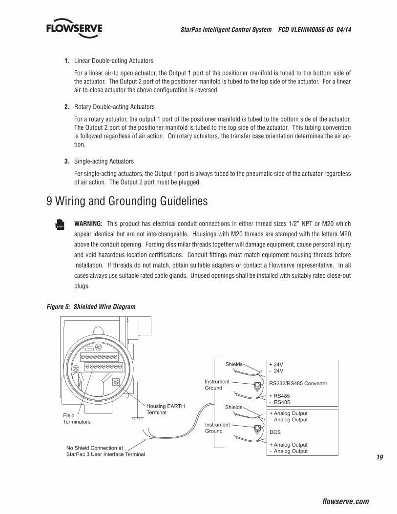
Figure 5: Shielded Wire Diagram
STOP!
Housing EARTHTerminalField
Terminators
+ 24V- 24V
RS232/RS485 Converter
+ RS485- RS485
No Shield Connection atStarPac 3 User Interface Terminal
InstrumentGround
InstrumentGround
Shields
Shields+ Analog Output- Analog Output
DCS
+ Analog Output- Analog Output
StarPac Intelligent Control System FCD VLENIM0066-05 04/14
20
®
9.1 Shielding Versus Grounding
All signals to the StarPac 3 unit should be in shielded cables. Shields must be tied to a ground at only one end of the
cable to provide a place for environmental electrical noise to be removed from the cable. A ground wire (unlike a shield)
is attached at both ends to provide a continuous path for electrical conductivity.
9.2 Grounding Screw
The green grounding screw, located by the customer interface terminal block should be used to provide the unit with an
adequate and reliable earth ground reference. This ground should be tied to the same ground as the electrical conduit.
Additionally, the electrical conduit connecting to the unit should be earth grounded at both ends of its run.
WARNING: The green grounding screw must not be used to terminate signal shield wires.
9.3 24 VDC Power
The 24 VDC connection points will work best with shielded twisted pair wire with the shield wire connected only at the
source. The input power is isolated within the unit and may be referenced to whatever level is necessary.
WARNING: The 24 VDC power supply should not be connected to earth ground.
9.4 RS-485 Communications
RS-485 wiring requires the use of a shielded twisted pair cable, which is grounded only at the source and not in the
unit. (For maximum performance, wire should have a characteristic impedance of 120 ohms.) The RS-485 input is fully
isolated, using opto-isolators.
The RS-485 allows only a 7 to 12 V common mode voltage differential between stations. RS-232 to RS-485 converters
are not a grounded connection. PC‘s with internal RS-485 cards, on the other hand, are often grounded. If another
ground communication device is on the network, a fault condition will almost certainly exist due to transient and steady
state differences in ground potential.
9.5 4-20 mA Command Input, Auxiliary Input and Feedback Output
These signals are isolated but shielded twisted pair wire should be used to reduce crosstalk from other signals. The
shield should be connected only at the source.
9.6 Discrete Inputs and Outputs
These signals are isolated, but because they are frequently used to switch high voltage (120 VAC), they should be run in
separate shielded wire paths away from the other StarPac 3 signals.
9.7 RS-232 to RS-485 Converter Connection
When connecting a StarPac 3 unit to a communication device, no shield or ground connections exist. Hence, the 24 VDC
power and RS-485 communication shield drain wires must be connected to a convenient ground near the converter.
STOP!
STOP!

21
StarPac Intelligent Control System FCD VLENIM0066-05 04/14
flowserve.com
®
10 Wiring the StarPac 3 System10.1 General
All electrical connections must be done according to local and industry electrical codes. Flowserve recommends a
shielded cable be used for the RS-485 command signal wire (e.g., Belden 9841 or equivalent).
When connecting multiple StarPac 3 units, a parallel daisy-chain wiring pattern is used. Connect unit‘s branch lines
to main line, keeping branch lines as short as possible. The total length of wiring should not exceed 4,000 feet (1,200
meters) without use of repeaters.
Avoid devices producing electrical ‘noise’ while installing the cable.
CAUTION: The following procedure should be performed on the bench or with the unit isolated so that unex-
pected valve stroking will not adversely affect the process.
WARNING: The following procedures may cause the valve to stroke, causing pressures and temperatures to
vary from their norms. Notify appropriate personnel that the valve may stroke unexpectedly. It is recommended that the
system be isolated from the process, if installed in line.
WARNING: Cable entry temperature may exceed 700 C. Therefore, select appropriate rated cable.
10.2 Wiring Connections
To connect the wiring to the StarPac 3 unit, refer to Figures 6 and Table IX, and then proceed as follows. Figure 6: User Interface Terminal Pinouts
1 32 4 5 6 7 8 9
10 11 13 14 1512 16 17 18
24 V
DC
+24
VD
C -
CO
M A
+C
OM
A -
CO
M B
+C
OM
B -
Ana
log
1 In
+
Ana
log
2 In
-
Ana
log
1 In
-A
nalo
g 2
In +
Ana
log
1 O
ut +
Ana
log
1 O
ut -
Ana
log
2 O
ut +
Ana
log
2 O
ut -
Dis
cret
e O
ut*
Dis
cret
e O
ut*
Dis
cret
e In
Dis
cret
e In
*Discrete Output can be configured for a pulse output or an alarm relay
STOP!
STOP!
StarPac Intelligent Control System FCD VLENIM0066-05 04/14
22
®
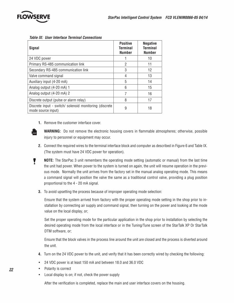
Table IX: User Interface Terminal Connections
SignalPositiveTerminal Number
Negative Terminal Number
24 VDC power 1 10Primary RS-485 communication link 2 11Secondary RS-485 communication link 3 12Valve command signal 4 13Auxiliary input (4-20 mA) 5 14Analog output (4-20 mA) 1 6 15Analog output (4-20 mA) 2 7 16
Discrete output (pulse or alarm relay) 8 17Discrete input - switch/ solenoid monitoring (discrete mode source input) 9 18
1. Remove the customer interface cover.
WARNING: Do not remove the electronic housing covers in flammable atmospheres; otherwise, possible
injury to personnel or equipment may occur.
2. Connect the required wires to the terminal interface block and computer as described in Figure 6 and Table IX.
(The system must have 24 VDC power for operation).
NOTE: The StarPac 3 unit remembers the operating mode setting (automatic or manual) from the last time the unit had power. When power to the system is turned on again, the unit will resume operation in the previ-ous mode. Normally the unit arrives from the factory set in the manual analog operating mode. This means a command signal will position the valve the same as a traditional control valve, providing a plug position proportional to the 4 - 20 mA signal.
3. To avoid upsetting the process because of improper operating mode selection:
Ensure that the system arrived from factory with the proper operating mode setting in the shop prior to in-stallation by connecting air supply and command signal, then turning on the power and looking at the mode value on the local display, or;
Set the proper operating mode for the particular application in the shop prior to installation by selecting the desired operating mode from the local interface or in the Tuning/Tune screen of the StarTalk XP Or StarTalk DTM software, or;
Ensure that the block valves in the process line around the unit are closed and the process is diverted around
the unit.
4. Turn on the 24 VDC power to the unit, and verify that it has been correctly wired by checking the following:
• 24 VDC power is at least 150 mA and between 18.0 and 36.0 VDC
• Polarity is correct
• Local display is on; if not, check the power supply
After the verification is completed, replace the main and user interface covers on the housing.
STOP!
23
StarPac Intelligent Control System FCD VLENIM0066-05 04/14
flowserve.com
®
10.3 Setting the Jumpers
The StarPac 3 system has several jumpers that are used to configure the analog and discrete I/O. The keypad must be
removed to view or change the jumper settings.
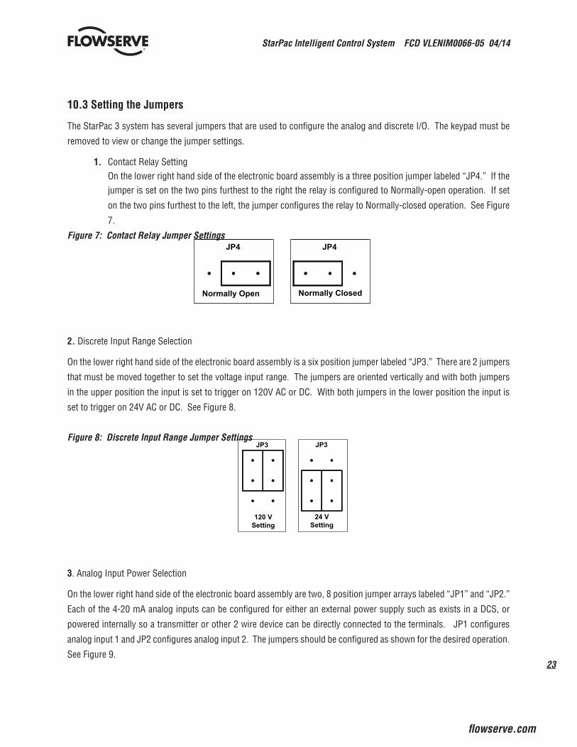
1. Contact Relay Setting On the lower right hand side of the electronic board assembly is a three position jumper labeled “JP4.” If the
jumper is set on the two pins furthest to the right the relay is configured to Normally-open operation. If set
on the two pins furthest to the left, the jumper configures the relay to Normally-closed operation. See Figure
7.
Figure 7: Contact Relay Jumper Settings
2. Discrete Input Range Selection
On the lower right hand side of the electronic board assembly is a six position jumper labeled “JP3.” There are 2 jumpers
that must be moved together to set the voltage input range. The jumpers are oriented vertically and with both jumpers
in the upper position the input is set to trigger on 120V AC or DC. With both jumpers in the lower position the input is
set to trigger on 24V AC or DC. See Figure 8.
Figure 8: Discrete Input Range Jumper Settings
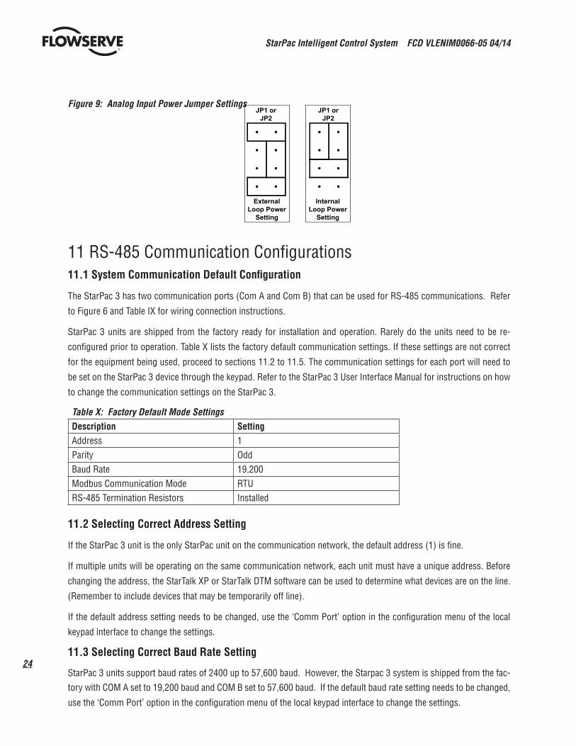
3. Analog Input Power Selection
On the lower right hand side of the electronic board assembly are two, 8 position jumper arrays labeled “JP1” and “JP2.”
Each of the 4-20 mA analog inputs can be configured for either an external power supply such as exists in a DCS, or
powered internally so a transmitter or other 2 wire device can be directly connected to the terminals. JP1 configures
analog input 1 and JP2 configures analog input 2. The jumpers should be configured as shown for the desired operation.
See Figure 9.
Normally Closed
JP4
Normally Open
JP4
JP3
24 VSetting
JP3
120 VSetting
StarPac Intelligent Control System FCD VLENIM0066-05 04/14
24
®
Figure 9: Analog Input Power Jumper Settings
11 RS-485 Communication Configurations11.1 System Communication Default Configuration
The StarPac 3 has two communication ports (Com A and Com B) that can be used for RS-485 communications. Refer
to Figure 6 and Table IX for wiring connection instructions.
StarPac 3 units are shipped from the factory ready for installation and operation. Rarely do the units need to be re-
configured prior to operation. Table X lists the factory default communication settings. If these settings are not correct
for the equipment being used, proceed to sections 11.2 to 11.5. The communication settings for each port will need to
be set on the StarPac 3 device through the keypad. Refer to the StarPac 3 User Interface Manual for instructions on how
to change the communication settings on the StarPac 3.
Table X: Factory Default Mode SettingsDescription SettingAddress 1Parity OddBaud Rate 19,200Modbus Communication Mode RTURS-485 Termination Resistors Installed
11.2 Selecting Correct Address Setting
If the StarPac 3 unit is the only StarPac unit on the communication network, the default address (1) is fine.
If multiple units will be operating on the same communication network, each unit must have a unique address. Before
changing the address, the StarTalk XP or StarTalk DTM software can be used to determine what devices are on the line.
(Remember to include devices that may be temporarily off line).
If the default address setting needs to be changed, use the ‘Comm Port’ option in the configuration menu of the local
keypad interface to change the settings.
11.3 Selecting Correct Baud Rate Setting
StarPac 3 units support baud rates of 2400 up to 57,600 baud. However, the Starpac 3 system is shipped from the fac-tory with COM A set to 19,200 baud and COM B set to 57,600 baud. If the default baud rate setting needs to be changed,
use the ‘Comm Port’ option in the configuration menu of the local keypad interface to change the settings.
JP1 orJP2
InternalLoop Power
Setting
JP1 orJP2
ExternalLoop Power
Setting
25
StarPac Intelligent Control System FCD VLENIM0066-05 04/14
flowserve.com
®
11.4 Selecting Correct Modbus Transmission Mode
Two transmission modes exist in a Modbus system, ASCII and RTU (default). Use the ASCII mode when transmitting information through a device that uses ASCII control codes; for example, a modem. When ASCII mode is used, Parity
must be set to None. Use the RTU mode when connecting directly to both devices; for example, an RS-485 interface card
wired directly to a StarPac 3 system.
If the default Modbus transmission mode setting needs to be changed, use the ‘Comm Port’ option in the configuration
menu of the local keypad interface to change the settings.
11.5 Selecting Proper RS-485 Termination Resistor Setting
A termination resistor must be installed on the two most remote devices on the network, counting the host computer as
any other device.
(For example, a single 3 unit and the RS-485 driver in the host computer would each require the termination resistor
to be installed. If four units were on the network with a host computer, decide which of the two devices have the most
combined cable length between them. These two devices should have the termination resistors installed. The termi-
nation resistors should be disabled in the devices not considered to be the most remote using the instructions in the
next section. Using more than two termination resistors in a network can cause the RS-485 communications to operate
erratically or fail).
On the top electronic board there are two termination jumpers for the RS-485 communications to the right of the LCD
display. The jumper labeled JP1 enables the termination resistor for Com A and the jumper labeled JP2 enables the
termination resistor for Com B. To enable 120 ohms termination, insert both jumpers for A and B channels. To disable
termination, remove both jumpers from each channel.
11.6 Communication Port B
Com Port B can be set for the following three configurations;
• RS-485
• USB
• Infrared
1. When RS-485 is selected, the StarPac 3 device will need to be wired correctly. Refer to Figure 6 and Table IX
for wiring connection instructions. Follow the instructions as outlined in sections 11.2 to 11.5 to configure
Com Port B.
2. When a 2.0 mini-B USB cable is plugged into the StarPac 3 on the Customer Interface Board, Com Port B will
automatically be configured for communication through the USB cable. The baud rate will automatically be
set to 57600. When using StarTalk XP or StarTalk DTM, make sure the computer com port baud rate setting
is also set to 57600.
3. When Infrared is selected, the StarPac 3 will be able to receive communication through the glass on the main
cover. It is not necessary to remove the main cover. Communication will need to occur using a PDA with
special software. The software will contain a keypad simulator that will have the same functionality as the
local keypad.
StarPac Intelligent Control System FCD VLENIM0066-05 04/14
26
®
12 StarPac 3 CalibrationFor complete calibration instructions, refer to the StarPac 3 Interface Manual or the on board help in the StarTalk XP or
StarTalk DTM interface software.
13 StarPac 3 ConfigurationFor complete configuration instructions, refer to the StarPac 3 User Interface Manual or the on board help in the Star-
Talk XP or StarTalk DTM interface software.
14 System Maintenance14.1 Overview
It is recommended that the StarPac 3 system calibration be checked every six months. If, after checking the unit, a
component is determined to be defective, the following section will help with the component replacement.
The following items may be needed to install, start up and calibrate the unit‘s electronics.
• Power supply: 24 VDC, 150 mA
• Digital volt meter with 4 - 20 mA range
• Air supply: 50 psig minimum, 80-100 psig preferred
• Gauges or the ability to accurately determine process pressures and valve air supply pressures
• 4 - 20 mA command source
• Thermocouple calibrator or simulator with 0 to 500° Celsius range (Preferably a K type thermocouple cali-
brator)
14.2 Mechanical Subsystem Maintenance
Refer to the appropriate Flowserve Installation, Operation & Maintenance (IOM) instructions for details on repair and
maintenance of the control valve actuator components. Please refer to the manufacturers’ manuals for maintenance
and operation instructions for non-pneumatic actuators, e.g., electric or electro-hydraulic actuators.
WARNING: The process line must be depressurized and drained of process fluid and decontaminated prior to
working on internal valve components. Failure to do so may cause serious injury to personnel.
1. Depressurize the line, decontaminate the valve (if needed) and shut off the air supply to the valve positioner.
2. Disconnect the actuator air tubes from the unit.
3. Disconnect the two mounting bolts that attach the StarPac 3 system bracket.
4. Disconnect the follower arm from the unit base. This is done by removing the follower arm nut and washer
and pulling the arm off the shaft. Notice that the shaft is slightly spring loaded.
5. The actuator subassembly is now isolated and is removed by loosening the bonnet bolts and lifting the actu-
ator away from the body.
6. The tubing holds the StarPac 3 base in place, eliminating the need to disconnect wiring or air connections.
STOP!
27
StarPac Intelligent Control System FCD VLENIM0066-05 04/14
flowserve.com
®
7. Standard valve maintenance may now be done on the actuator or valve body components. Refer to the Flow-
serve IOM instructions for details on such things as trim or packing replacement. If you have to replace the
trim, use the same trim number and characteristic as the original trim so the flow calculations are not affected.
If a trim size change is needed, contact your Flowserve representative to find out about flow characterization
options.
8. Reassemble the system by reversing the above steps. Be sure to follow the procedures outlined in the Flow-
serve Installation, Operation and Maintenance (IOM) instructions for valve reassembly. When reconnecting
the follower arm, make sure that the arm fits correctly on the keyed shaft and has a positive spring action.
9. Turn on the air supply to the valve and check for leaks in the reattached actuator tubing lines.
10. Turn on power to the unit. Check the system calibration and perform a Valve Stroke Calibration to reset the
position feedback. Refer to the Calibration section of the StarPac 3 User Interface Manual.
14.3 Position Feedback System
The position feedback linkage of the StarPac 3 system is a critical part of the system. This linkage is also used in the
StarPac 3 to calculate the valve’s CV for a given stroke for flow measurement. This linkage should be lubricated and
checked periodically for tight, smooth operation. The follower arm should operate smoothly with no binding and have
a positive spring loading on the arm. Inspect the follower arm pin for excess wear and replace if needed. The take-off
arm attached to the stem clamp must be firmly secured to the stem clamp and perpendicular to the actuator stem. If
this takeoff arm is canted or misaligned, problems may occur with positioner calibration and the position reading on
the unit may go out of range.
On rotary actuators, make sure the adjustment linkage locknut is tight and has no excessive play in the ball joints. The
rotary shaft clamp must be tight and should not freely rotate on the shaft.
14.4 Pressure Sensor Replacement
Standard StarPac 3 pressure sensors are typically installed directly into the control valve body. Before they can be
removed, the process line must be depressurized and drained of all fluids and the valve decontaminated.
To replace a pressure sensor, refer to Figure 10 then proceed as follows.
WARNING: The process line must be depressurized and drained of process fluid, and decontaminated prior to
working on internal valve components. Failure to do so may cause serious injury to personnel.
WARNING: If the pressure sensors are remote mounted, the sensor will be located in a sensor housing in the
tubing line and not in the sensor housing located on the valve body. This section of the tubing contains pro-
cess fluid and must be drained and decontaminated before the sensor is removed. The procedure for sensor
removal and replacement will be similar to that outlined below.
(Refer to alternate sensor information when this type of sensor is included with system.)
1. Depressurize and decontaminate the line and valve. Loosen the tubing nuts on the conduit leading to the
pressure sensor, if applicable.
2. Loosen the sensor nut.
3. Gently pull the conduit and sensor nut approximately 1/2” to 3/4” from the sensor. Use needle nose pliers to
STOP!
STOP!
StarPac Intelligent Control System FCD VLENIM0066-05 04/14
28
®
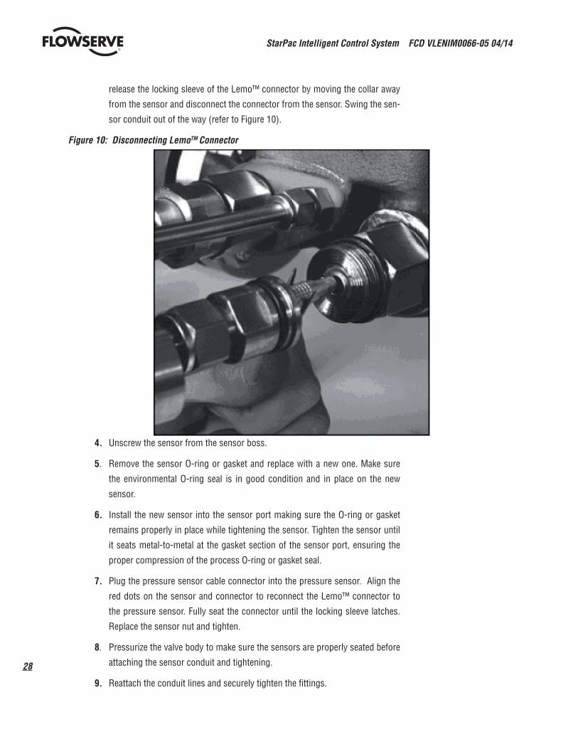
release the locking sleeve of the Lemo™ connector by moving the collar away
from the sensor and disconnect the connector from the sensor. Swing the sen-
sor conduit out of the way (refer to Figure 10).
Figure 10: Disconnecting LemoTM Connector
4. Unscrew the sensor from the sensor boss.
5. Remove the sensor O-ring or gasket and replace with a new one. Make sure
the environmental O-ring seal is in good condition and in place on the new
sensor.
6. Install the new sensor into the sensor port making sure the O-ring or gasket
remains properly in place while tightening the sensor. Tighten the sensor until
it seats metal-to-metal at the gasket section of the sensor port, ensuring the
proper compression of the process O-ring or gasket seal.
7. Plug the pressure sensor cable connector into the pressure sensor. Align the
red dots on the sensor and connector to reconnect the Lemo™ connector to
the pressure sensor. Fully seat the connector until the locking sleeve latches.
Replace the sensor nut and tighten.
8. Pressurize the valve body to make sure the sensors are properly seated before
attaching the sensor conduit and tightening.
9. Reattach the conduit lines and securely tighten the fittings.
29
StarPac Intelligent Control System FCD VLENIM0066-05 04/14
flowserve.com
®
14.5 Pressure Sensor Cable Replacement
It is not necessary to remove the pressure sensor prior to replacing the pressure sensor cable.
1. Loosen the tubing nuts on the conduit leading to the pressure sensor, if applicable.
2. Loosen the sensor nut.
3. Gently pull the conduit and sensor nut approximately 1/2” to 3/4” from the sensor. Use needle nose pliers to
release the locking sleeve of the Lemo™ connector by moving the collar away from the sensor and disconnect
the connector from the sensor. Swing the sensor conduit out of the way (refer to Figure 10).
4. Remove the main cover.
5. Remove the two keypad retaining screws. Carefully pull the keypad away from the main PCB board. Unplug
the keypad ribbon cable from the main PCB board and remove the keypad.
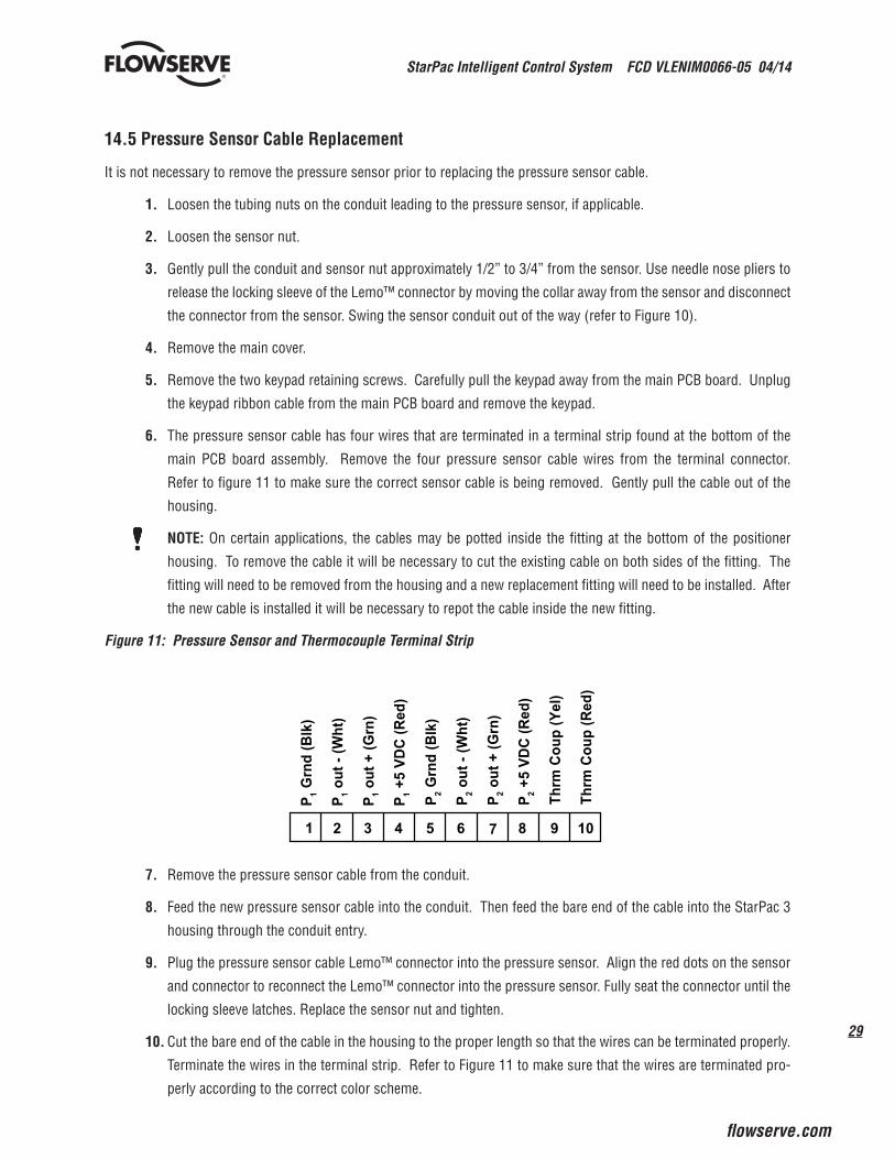
6. The pressure sensor cable has four wires that are terminated in a terminal strip found at the bottom of the
main PCB board assembly. Remove the four pressure sensor cable wires from the terminal connector.
Refer to figure 11 to make sure the correct sensor cable is being removed. Gently pull the cable out of the
housing.
NOTE: On certain applications, the cables may be potted inside the fitting at the bottom of the positioner
housing. To remove the cable it will be necessary to cut the existing cable on both sides of the fitting. The
fitting will need to be removed from the housing and a new replacement fitting will need to be installed. After
the new cable is installed it will be necessary to repot the cable inside the new fitting.
Figure 11: Pressure Sensor and Thermocouple Terminal Strip
7. Remove the pressure sensor cable from the conduit.
8. Feed the new pressure sensor cable into the conduit. Then feed the bare end of the cable into the StarPac 3
housing through the conduit entry.
9. Plug the pressure sensor cable Lemo™ connector into the pressure sensor. Align the red dots on the sensor
and connector to reconnect the Lemo™ connector into the pressure sensor. Fully seat the connector until the
locking sleeve latches. Replace the sensor nut and tighten.
10. Cut the bare end of the cable in the housing to the proper length so that the wires can be terminated properly.
Terminate the wires in the terminal strip. Refer to Figure 11 to make sure that the wires are terminated pro-
perly according to the correct color scheme.
P 1)klB( dnr
G
P 1)th
W( - tuo
P 1)nr
G( + tuo
P 1)deR( CDV 5+
1
P 2)klB( dnr
G
P 2)th
W( - tuo
P 2)nr
G( + tuo
P 2)deR( CDV 5+
)leY( puoC mrhT
)deR( puoC mrhT
2 3 4 5 6 7 8 9 10

StarPac Intelligent Control System FCD VLENIM0066-05 04/14
30
®
14.6 Thermocouple Replacement
In normal configuration, the thermocouple does not penetrate the valve body wall. Depres-
surizing the body is not necessary when replacing the thermocouple.
WARNING: If the StarPac II was ordered with a special thermocouple option,
verify the need to depressurize the body before proceeding.
1. Disconnect power and air supply to the unit.
2. Remove the main cover.
3. Remove the two keypad retaining screws. Carefully pull the keypad away from
the main PCB board. Unplug the keypad ribbon cable from the main PCB board
and remove the keypad.
4. Disconnect the red and yellow thermocouple wire. Refer to Figure 11.
5. Loosen the tubing nuts on both ends of the thermocouple assembly (refer to
Figure 12).
Figure 12: Thermocouple Replacement
6. Pull the wires out of the StarPac base and slip the tubing off the wires.
NOTE: On certain applications, the cables may be potted inside the fitting at the
bottom of the positioner housing. To remove the cable it will be necessary to
cut the existing cable on both sides of the fitting. The fitting will need to be re-
moved from the housing and a new replacement fitting will need to be installed.
After the new cable is installed it will be necessary to repot the cable inside the
new fitting.
7. Unscrew the old thermocouple from the body.
STOP!
31
StarPac Intelligent Control System FCD VLENIM0066-05 04/14
flowserve.com
®
8. Install the new thermocouple.
9. Feed the wires back through the tubing and into the StarPac housing.
10. Tighten the tubing nuts.
11. Cut the thermocouple wires to length. Strip and reattach wires to the terminal block, noting color polarity.
(The red wire is the negative signal).
12. Check that all the fittings are tight.
14.7 Keypad Assembly Replacement
If, after consulting with the local Flowserve or factory representative, the StarPac 3’s keypad is found to be defective and
needs replacement, refer to Figure 24 and proceed as follows.
1. Make sure valve is by-passed and in a safe condition.
2. Disconnect the power and air supply to the unit.
3. Remove main housing cover.
4. Remove the two keypad retaining screws. Carefully pull the keypad away from the main PCB board. Unplug
the keypad ribbon cable from the main PCB board and remove the keypad.
5. Install the new keypad assembly by first plugging the keypad ribbon cable into the connector on the main PCB
board. Carefully place the keypad over the main PCB board.
6. Re-insert the two keypad retaining screws. Do not over-tighten.
14.8 Driver Module Assembly Replacement
The driver module assembly moves the spool valve by means of a differential pressure across its diaphragm. Air is
routed to the driver module from the regulator through a flexible hose. A barbed fitting connects the flexible hose to the
driver module assembly. Wires from the driver module assembly connect the hall effect sensor and modulator to the
main PCB assembly.
To replace the driver module assembly, refer to Figures 13, 14, 15 and 16 and proceed as outlined below. The
following tools are required:
• Flat plate or bar about 1/8” thick
• Phillips screwdriver
• 1/4” nutdriver
WARNING: Observe precautions for handling electrostatically sensitive devices.STOP!
StarPac Intelligent Control System FCD VLENIM0066-05 04/14
32
®
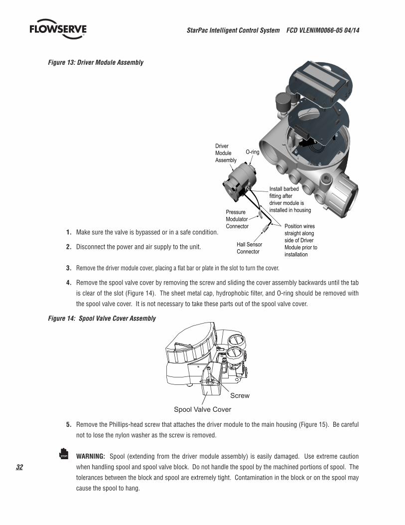
Figure 13: Driver Module Assembly
1. Make sure the valve is bypassed or in a safe condition.
2. Disconnect the power and air supply to the unit.
3. Remove the driver module cover, placing a flat bar or plate in the slot to turn the cover.
4. Remove the spool valve cover by removing the screw and sliding the cover assembly backwards until the tab
is clear of the slot (Figure 14). The sheet metal cap, hydrophobic filter, and O-ring should be removed with
the spool valve cover. It is not necessary to take these parts out of the spool valve cover.
Figure 14: Spool Valve Cover Assembly
5. Remove the Phillips-head screw that attaches the driver module to the main housing (Figure 15). Be careful
not to lose the nylon washer as the screw is removed.
WARNING: Spool (extending from the driver module assembly) is easily damaged. Use extreme caution
when handling spool and spool valve block. Do not handle the spool by the machined portions of spool. The
tolerances between the block and spool are extremely tight. Contamination in the block or on the spool may
cause the spool to hang.
Hall SensorConnector
Install barbedfitting afterdriver module isinstalled in housingPressure
ModulatorConnector
O-ringDriverModuleAssembly
Position wiresstraight alongside of DriverModule prior toinstallation
Screw
Spool Valve Cover
STOP!

33
StarPac Intelligent Control System FCD VLENIM0066-05 04/14
flowserve.com
®
Figure 15: Spool and Block
6. Remove the spool valve by the two Phillips-head screws and carefully sliding the block off the spool (Figure
15).
7. Carefully remove the spool by sliding the end of the spool out of the connection clip. Excessive force may
bend spool.
8. Remove the main cover.
9. Remove the two keypad retaining screws. Carefully pull the keypad away from the main PCB board. Unplug
the keypad ribbon cable from the main PCB board and remove the keypad.
10. Remove the main PCB assembly by following the instructions in section 14.15 of this manual.
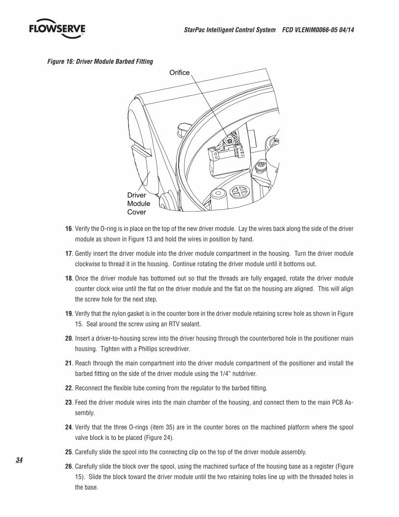
11. Disconnect the flexible tubing from the barbed fitting at the driver module assembly (see Figure 16).
12. Use the 1/4” nutdriver to remove the barbed fitting from the driver module assembly.
13. Feed the two wire connectors on the driver module back into the driver module compartment so that they
stick out the driver module opening (See Figure 13). This will allow the driver module to thread out without
tangling or cutting the wires.
14. Grasp the base of the driver module and turn it counter clockwise to remove. After it is threaded out, carefully
retract the driver module from the housing.
15. Remove the barbed fitting orifice (See Figure 16) from the side of the new driver module using the 1/4” nut-
driver.
Housing
SpoolValve Block
Spool
Driver toHousing ScrewNylon
Gasket
Spool ValveScrew
StarPac Intelligent Control System FCD VLENIM0066-05 04/14
34
®
Figure 16: Driver Module Barbed Fitting
16. Verify the O-ring is in place on the top of the new driver module. Lay the wires back along the side of the driver
module as shown in Figure 13 and hold the wires in position by hand.
17. Gently insert the driver module into the driver module compartment in the housing. Turn the driver module
clockwise to thread it in the housing. Continue rotating the driver module until it bottoms out.
18. Once the driver module has bottomed out so that the threads are fully engaged, rotate the driver module
counter clock wise until the flat on the driver module and the flat on the housing are aligned. This will align
the screw hole for the next step.
19. Verify that the nylon gasket is in the counter bore in the driver module retaining screw hole as shown in Figure
15. Seal around the screw using an RTV sealant.
20. Insert a driver-to-housing screw into the driver housing through the counterbored hole in the positioner main
housing. Tighten with a Phillips screwdriver.
21. Reach through the main compartment into the driver module compartment of the positioner and install the
barbed fitting on the side of the driver module using the 1/4” nutdriver.
22. Reconnect the flexible tube coming from the regulator to the barbed fitting.
23. Feed the driver module wires into the main chamber of the housing, and connect them to the main PCB As-
sembly.
24. Verify that the three O-rings (item 35) are in the counter bores on the machined platform where the spool
valve block is to be placed (Figure 24).
25. Carefully slide the spool into the connecting clip on the top of the driver module assembly.
26. Carefully slide the block over the spool, using the machined surface of the housing base as a register (Figure
15). Slide the block toward the driver module until the two retaining holes line up with the threaded holes in
the base.
Orifice
DriverModuleCover
35
StarPac Intelligent Control System FCD VLENIM0066-05 04/14
flowserve.com
®
27. Install two spool-valve screws and tighten securely with a Phillips screwdriver (See Figure 15).
28. Slide the spool valve cover assembly over the spool valve until the tang engages in the housing slot. Install
spool valve cover screw and tighten securely (see Figure 14).
29. Re-install the main PCB assembly following the instructions found in section 14.15 of this manual.
30. Re-install the keypad. Insert the two retaining screws and tighten evenly, using a Phillips a screwdriver. Do
not over-tighten.
31. Reconnect power and air supply to the positioner and perform a stroke calibration. Refer to the Calibration
section of the StarPac 3 User Interface Manual.
32. Reinstall all covers.
14.9 Regulator Replacement
The Regulator reduces the pressure of the incoming supply air to a level that the driver module can use.
To replace the regulator, refer to Figure 24 and proceed as outlined below. The following tools are required:
• Phillips screwdriver
• 1/4” nutdriver
WARNING: Observe precautions for handling electrostatically sensitive devices.
1. Make sure valve is bypassed or in a safe condition.
2. Disconnect the power and air supply to the unit.
3. Remove the main cover.
4. Remove the two keypad retaining screws. Carefully pull the keypad away from the main PCB board. Unplug
the keypad ribbon cable from the main PCB board and remove the keypad.
5. Remove the main PCB assembly by following the instructions in section 14.15 of this manual.
6. Remove the four screws from the regulator base. Verify that as the regulator is removed, the O-ring and filter
remain in the counterbore (see Figure 20).
7. Remove tubing and barbed fitting from the regulator base.
8. Install barbed fitting and tubing to the new regulator.
9. Verify that the O-ring and filter are in the counterbore. Install new regulator using 8-32 x 1/2” screws.
10. Install the main PCB assembly into the housing by following the instructions in 14.15 of this manual.
11. Reinstall the keypad. Insert the two retaining screws. Do not over-tighten.
12. Reinstall all covers.
14.10 Checking or Setting Internal Regulator PressureTo check or set the internal regulator pressure, refer to Figure 16 and proceed as outlined below. The tools and equip-
ment used in the next procedure are from indicated vendors. The following tools are required:
STOP!
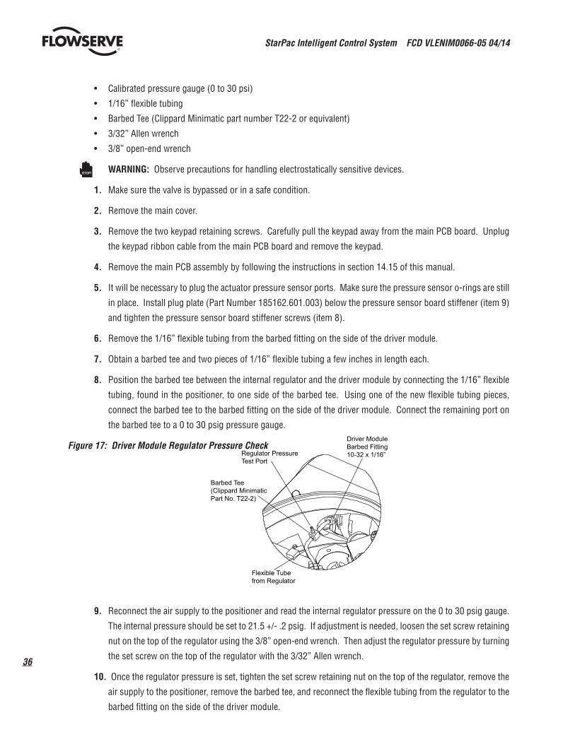
StarPac Intelligent Control System FCD VLENIM0066-05 04/14
36
®
• Calibrated pressure gauge (0 to 30 psi)
• 1/16” flexible tubing
• Barbed Tee (Clippard Minimatic part number T22-2 or equivalent)
• 3/32” Allen wrench
• 3/8” open-end wrench
WARNING: Observe precautions for handling electrostatically sensitive devices.
1. Make sure the valve is bypassed or in a safe condition.
2. Remove the main cover.
3. Remove the two keypad retaining screws. Carefully pull the keypad away from the main PCB board. Unplug
the keypad ribbon cable from the main PCB board and remove the keypad.
4. Remove the main PCB assembly by following the instructions in section 14.15 of this manual.
5. It will be necessary to plug the actuator pressure sensor ports. Make sure the pressure sensor o-rings are still
in place. Install plug plate (Part Number 185162.601.003) below the pressure sensor board stiffener (item 9)
and tighten the pressure sensor board stiffener screws (item 8).
6. Remove the 1/16” flexible tubing from the barbed fitting on the side of the driver module.
7. Obtain a barbed tee and two pieces of 1/16” flexible tubing a few inches in length each.
8. Position the barbed tee between the internal regulator and the driver module by connecting the 1/16” flexible
tubing, found in the positioner, to one side of the barbed tee. Using one of the new flexible tubing pieces,
connect the barbed tee to the barbed fitting on the side of the driver module. Connect the remaining port on
the barbed tee to a 0 to 30 psig pressure gauge.
Figure 17: Driver Module Regulator Pressure Check
9. Reconnect the air supply to the positioner and read the internal regulator pressure on the 0 to 30 psig gauge.
The internal pressure should be set to 21.5 +/- .2 psig. If adjustment is needed, loosen the set screw retaining
nut on the top of the regulator using the 3/8” open-end wrench. Then adjust the regulator pressure by turning
the set screw on the top of the regulator with the 3/32” Allen wrench.
10. Once the regulator pressure is set, tighten the set screw retaining nut on the top of the regulator, remove the
air supply to the positioner, remove the barbed tee, and reconnect the flexible tubing from the regulator to the
barbed fitting on the side of the driver module.
STOP!
Regulator PressureTest Port
Driver ModuleBarbed Fitting10-32 x 1/16”
Barbed Tee(Clippard MinimaticPart No. T22-2)
Flexible Tubefrom Regulator

37
StarPac Intelligent Control System FCD VLENIM0066-05 04/14
flowserve.com
®
11. Remove the stiffener plate and plug plate. Make sure that the o-rings stay in place.
12. Re-install the main PCB assembly following the instructions found in section 14.15 of this manual.
13. Re-install the keypad. Insert the two retaining screws and tighten evenly, using a Phillips a screwdriver. Do
not over-tighten.
14. Re-install all covers.
14.11 Checking or Setting the Driver Module Minimum Pressure
To check or set the driver module minimum pressure, refer to Figure 18 and proceed as outlined below. The tools and
equipment used in the next procedure are from indicated vendors. The following tools are required:
• Calibrated pressure gauge (0 to 30 psi)
• 1/16” flexible tubing
• Barbed Tee (Pneumadyne part No. SFL-10 or equivalent))
• No. 10-32 extension (Clippard part No. 15010 or equivalent)
• 9/64” Allen wrench
• 3/8” open-end wrench
WARNING: Observe precautions for handling electrostatically sensitive devices.
1. Make sure valve is bypassed or in a safe condition.
2. Disconnect power and air supply from the positioner.
3. Remove the main cover.
4. Remove the two keypad retaining screws. Carefully pull the keypad away from the main PCB board. Unplug
the keypad ribbon cable from the main PCB board and remove the keypad.
5. Remove the main PCB assembly by following the instructions in section 14.15 of this manual.
6. It will be necessary to plug the actuator pressure sensor ports. Make sure the pressure sensor o-rings are still
in place. Install plug plate (Part Number 185162.601.003) below the pressure sensor board stiffener (item 9)
and tighten the pressure sensor board stiffener screws (item 8).
7. Remove the 1/16” flexible tubing from the orifice.
8. Obtain a No. 10-32 swivel run tee (Pneumadyne part No. SFL-10 or equivalent) and a No. 10-32 extension
(Clippard part No. 15010 or equivalent).
9. Remove the No. 10-32 x 1/16 orifice (Figure 16) from the driver module using a 1/4-inch nut driver.
10. Screw in the 10-32 extension followed by the 10-32 x swivel run tee.
STOP!

StarPac Intelligent Control System FCD VLENIM0066-05 04/14
38
®
Figure 18: Driver Module Minimum Pressure Check
11. Direct the swivel run tee so the minimum pressure test port is accessible.
12. Screw a No. 10-32 x 1/16-inch barb fitting into the test port, and screw a No. 10-32 x 1/16 barb fitting into the
end of the elbow as shown.
13. Connect the tubing from the internal regulator output port to the orifice.
14. Using some 1/16-inch flexible tubing, connect a 0 to 30 psi gauge to the minimum pressure set port.
15. Once the gauge is connected, re-apply the positioner air supply (do not apply power). The minimum pressure
should now be registering on the gauge and must be 1.8 to 2.2 psi. If the minimum pressure is not correct, take a 9/64 allen wrench and turn the minimum pressure set screw located at the bottom of the driver module (Figure 12) until the pressure is in the range indicated. Cycle the positioner air supply several times and recheck the minimum pressure and re-adjust, if necessary, to ensure that the pressure has settled within the range specified.
16. When the pressure is set, remove the air supply.
17. Remove the No. 10-32 x 1/16 barb fittings from the swivel run tee and then remove the extension.
18. Replace the No. 10-32 x 1/16 barb fitting as shown in Figure 16 and reconnect the 1/16” flexible tubing from
the internal regulator output port to the orifice.
19. Remove the stiffener plate and plug plate. Make sure that the o-rings stay in place.
20. Re-install the main PCB assembly following the instructions found in section 14.15 of this manual.
21. Re-install the keypad. Insert the two retaining screws and tighten evenly, using a Phillips a screwdriver. Do
not over-tighten.
22. Re-install all covers.
23. Reconnect the positioner air supply and power. The positioner should now be ready to calibrate.
Minimum PressureTest Port
No.10-32 x 1/16
No.10-32 x SwivelTee (PneumadynePart No. SFL-10)
No.10-32 x .016Orifice
Pressure from InternalRegulator to be tubed tothis orifice
No. 10-32 Extension(Clippard Part No. 15010)
Barb
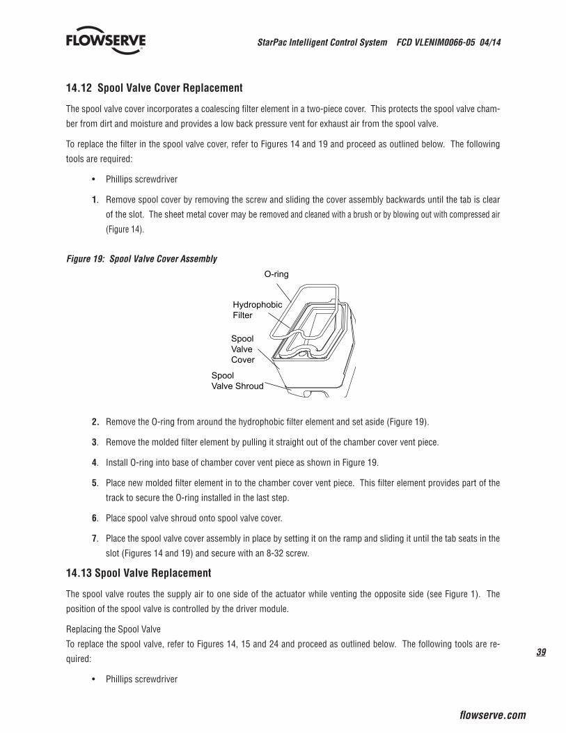
39
StarPac Intelligent Control System FCD VLENIM0066-05 04/14
flowserve.com
®
14.12 Spool Valve Cover Replacement
The spool valve cover incorporates a coalescing filter element in a two-piece cover. This protects the spool valve cham-
ber from dirt and moisture and provides a low back pressure vent for exhaust air from the spool valve.
To replace the filter in the spool valve cover, refer to Figures 14 and 19 and proceed as outlined below. The following
tools are required:
• Phillips screwdriver
1. Remove spool cover by removing the screw and sliding the cover assembly backwards until the tab is clear
of the slot. The sheet metal cover may be removed and cleaned with a brush or by blowing out with compressed air
(Figure 14).
Figure 19: Spool Valve Cover Assembly
2. Remove the O-ring from around the hydrophobic filter element and set aside (Figure 19).
3. Remove the molded filter element by pulling it straight out of the chamber cover vent piece.
4. Install O-ring into base of chamber cover vent piece as shown in Figure 19.
5. Place new molded filter element in to the chamber cover vent piece. This filter element provides part of the
track to secure the O-ring installed in the last step.
6. Place spool valve shroud onto spool valve cover.
7. Place the spool valve cover assembly in place by setting it on the ramp and sliding it until the tab seats in the
slot (Figures 14 and 19) and secure with an 8-32 screw.
14.13 Spool Valve Replacement
The spool valve routes the supply air to one side of the actuator while venting the opposite side (see Figure 1). The
position of the spool valve is controlled by the driver module.
Replacing the Spool Valve
To replace the spool valve, refer to Figures 14, 15 and 24 and proceed as outlined below. The following tools are re-
quired:
• Phillips screwdriver
O-ring
HydrophobicFilter
SpoolValveCover
SpoolValve Shroud
StarPac Intelligent Control System FCD VLENIM0066-05 04/14
40
®
1. Make sure the valve is bypassed or in a safe condition.
2. Disconnect the power and air supply to the unit.
3. Remove the spool valve cover by removing the screw and sliding the cover assembly backwards until the tab
is clear of the slot. It is not necessary to remove the sheet metal cap, hydrophobic filter, or O-ring from this
assembly (Figure 14).
WARNING: The spool (extending from the driver module assembly) is easily damaged. Use extreme caution
when handling spool and spool valve block. Do not handle the spool by the machined portions of spool. The
tolerances between the block and spool are extremely tight. Contamination in the block or on the spool may
cause the spool to hang.
4. Remove the spool valve block by removing the two Phillips-head screws and carefully sliding the block off the
spool (Figure 14).
5. Carefully remove spool by sliding end of spool out of connecting clip. Excessive force may bend the spool.
6. Verify that the three O-rings are in the counter bores on the machined platform where the new spool valve
block is to be placed (Figure 24).
7. Carefully slide the spool into the connecting clip on the top of the driver module assembly.
8. Carefully slide the block over the spool, using the machined surface of the housing base as a register (Figure
15). Slide the block toward the driver module until the two retaining holes line up with the threaded holes in
the base.
9. Install two spool-valve screws and tighten securely with a Phillips screwdriver (See Figure 15).
10. Slide the spool valve cover assembly over the spool valve until the tang engages in the housing slot. Install
spool valve cover screw and tighten securely (see Figure 14).
11. Reconnect power and air supply to the positioner and perform a stroke calibration.
14.14 Stem Position Sensor Replacement
The position feedback assembly transmits valve position information to the processor. This is accomplished by means of a rotary position sensor that connects to the valve stem through a feedback linkage. To provide for accurate tracking of the pin in the slot, the follower arm is biased against one side of the slot.
To replace the stem position sensor, refer to Figure 20 and proceed as outlined below. The following tools are required:
• Phillips screwdriver
WARNING: Observe precautions for handling electrostatically sensitive devices.
1. Make sure the valve is bypassed or in a safe condition.
2. Disconnect the power and air supply to the unit.
3. Remove the main cover.
4. Remove the two keypad retaining screws. Carefully pull the keypad away from the main PCB board. Unplug
the keypad ribbon cable from the main PCB board and remove the keypad.
5. Remove the main PCB assembly by following the instructions in section 14.15 of this manual.
STOP!
STOP!

41
StarPac Intelligent Control System FCD VLENIM0066-05 04/14
flowserve.com
®
6. Remove the two rotary position sensor-retaining screws and lift the sensor out of the housing.
7. Turn the new position sensor shaft until the dot on the side of the shaft is aligned with the wires on the side
of the position sensor (Figure 20).
Figure 20: Stem Position Sensor Orientation
8. Insert the position sensor into the shaft with the wires pointing toward the main PCB assembly. Turn the
position sensor clock-wise until bolting slots align with the housing screw holes and the wires on the sensor
protrude over the main PCB assembly.
9. Carefully center the position sensor on the shaft bore, insert and tighten the screws. Do not over-tighten.
10. Route the wires along the side of the position sensor and reconnect to the main PCB assembly.
11. Re-install the main PCB assembly following the instructions found in section 14.15 of this manual.
12. Re-install the keypad. Insert the two retaining screws and tighten evenly, using a Phillips a screwdriver. Do
not over-tighten.
13. Reinstall all covers.
14. Reconnect power and air supply to the positioner and perform a stroke calibration.
14.15 Main PCB Assembly Replacement
The main printed circuit board (PCB) assembly contains the circuit board and processor that perform control functions
of the positioner. The main PCB is to be replaced as a unit. None of the components on the main PCB are serviceable.
To replace the main PCB assembly, refer to Figure 20 and proceed as outlined below. The main PCB assembly consists of three
boards. The top board will have to be separated from the assembly. The bottom two boards will not have to be separated and will
remain together.
Housing
StemPositionSensor
FeedbackShaft
BearingStem PositionSensor Dot
SensorCable

StarPac Intelligent Control System FCD VLENIM0066-05 04/14
42
®
The following tools are required:
• Phillips screwdriver
WARNING: Observe precautions for handling electrostatically sensitive devices.
1. Make sure the valve is bypassed or in a safe condition.
2. Disconnect the power and air supply to the unit.
3. Remove the main cover.
4. Remove the keypad by removing the two retaining screws. Unplug the keypad ribbon cable from the main
PCB board and remove the keypad.
Figure 21: Main PCB Assembly
STOP!
Keypad
Main PCBAssembly
Regulator

43
StarPac Intelligent Control System FCD VLENIM0066-05 04/14
flowserve.com
®
5. Unplug the wire harness that terminates the pressure sensors and thermocouple from the main PCB assem-
bly.
6. Remove the three retaining screws (item 6) from the main PCB assembly.
7. Carefully unplug and remove the top display board from the main PCB assembly. The bottom two boards of
the main PCB assembly will remain in the housing.
8. Remove the two screws (item 8) retaining the lower two boards of the main PCB assembly. Remove the metal
pressure sensor board stiffener.
9. Carefully lift the lower two boards out of the main PCB assembly. Disconnect the three wire connections and
user interface ribbon cable from the back of the lowest board of the main PCB assembly.
10. Remove the lower two boards of the main PCB assembly out of the housing.
11. Prior to installing the new main PCB assembly, remove the top display board of the new main PCB assem-
bly.
12. Connect the three wire connections and user interface ribbon cable on to the back of the lowest board of the
main PCB assembly.
13. Verify that the two pressure sensor O-rings (item 10) are in place in the housing.
14. Place the lower two boards of the main PCB assembly into the positioner and onto the bosses in the housing.
Make sure all wires are clear and do not get pinched between bottom circuit board and the housing bosses.
15. While holding the metal pressure sensor board stiffener in place, insert the two retaining screws through the
metal pressure sensor board stiffener and circuit board and fasten the lower two boards to the housing. An
outline of where the where the metal stiffener needs to be placed can be seen on the middle board of the main
PCB assembly. Tighten the screws evenly to 8 in-lb.
16. Connect the pressure sensor/thermocouple wire harness to the middle board of the main PCB assembly.
17. Carefully plug the top display board of the main PCB assembly into the middle board of the main PCB assem-
bly.
18. Insert the three retaining screws through the mounting holes of the fully assembled main PCB assembly and
tighten evenly.
19. Carefully re-install the keypad assembly. Make sure that the connector on the back of the keypad assembly
connects correctly to the connector on the main PCB board.
20. Insert the two retaining screws through the keypad and tighten evenly. Do not over-tighten.
14.16 Customer Interface Board Replacement
The customer interface board provides a connection point inside the explosion-proof housing for all hookups to the
positioner.
To replace the customer interface board, refer to Figures 5 and 24 and proceed as outlined below. The following tools
are required:
• Phillips screwdriver
StarPac Intelligent Control System FCD VLENIM0066-05 04/14
44
®
WARNING: Observe precautions for handling electrostatic sensitive devices.
1. Make sure the valve is bypassed or in a safe condition.
2. Remove the main cover.
3. Remove the keypad assembly by removing the two retaining screws. Unplug the keypad ribbon cable from
the main PCB board and remove the keypad.
4. Remove the main PCB assembly as outlined in section 14.15.
5. Remove the user interface cover.
6. Disconnect the field wiring from the customer interface board terminals and remove the two screws (Item 19)
that hold the customer interface board in the housing (See Figure 5).
7. Remove the customer interface board by gently pulling it out of the housing.
8. Install the replacement customer interface board by sliding it into place.
9. Connect the ribbon cable on the customer interface board to the main PCB assembly. Install the main PCB
assembly as outlined in section 14.15.
10. Secure the customer interface in place with the two mounting screws (see Figure 5).
11. Reconnect the field wiring to the customer interface board terminals.
12. Install the keypad assembly and secure with the two retaining screws.
13. Reinstall all covers.
15 Optional Vented Design
A standard StarPac 3 is vented directly to the atmosphere. When supply air is substituted with sweet natural gas, piping must be used to route the exhausted natural gas to a safe environment. This piping system may cause some positioner back pressure in the main chamber (from the modulator) and spool chamber (from the actuator). Back pressure limita-tions are described below.
Two chambers must be vented on the StarPac 3: the driver module and the spool valve chamber (Figures 22 and 23). The driver module vent is located on the driver module cover. Install a tube fitting into the driver module cover (Figure 22). Connect the necessary tubing/piping to this fitting to route the exhausted natural gas to a safe environment.
The maximum allowable back pressure from the collection device on the driver module vent is 2.0 psig (0.14 barg). Vent
flow rate is 0.5 std ft3/min (1.4 std liter/min).
WARNING: The back pressure in the driver module housing must never rise above 2.0 psig (0.14 barg).
STOP!
STOP!
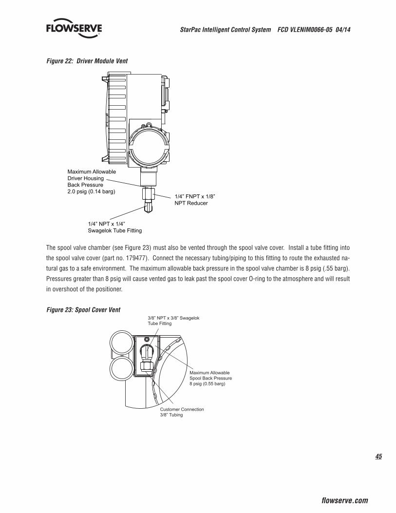
45
StarPac Intelligent Control System FCD VLENIM0066-05 04/14
flowserve.com
®
Figure 22: Driver Module Vent
Maximum AllowableDriver HousingBack Pressure2.0 psig (0.14 barg)
1/4” NPT x 1/4”Swagelok Tube Fitting
1/4” FNPT x 1/8”NPT Reducer
The spool valve chamber (see Figure 23) must also be vented through the spool valve cover. Install a tube fitting into
the spool valve cover (part no. 179477). Connect the necessary tubing/piping to this fitting to route the exhausted na-
tural gas to a safe environment. The maximum allowable back pressure in the spool valve chamber is 8 psig (.55 barg).
Pressures greater than 8 psig will cause vented gas to leak past the spool cover O-ring to the atmosphere and will result
in overshoot of the positioner.
Figure 23: Spool Cover Vent3/8” NPT x 3/8” SwagelokTube Fitting
Maximum AllowableSpool Back Pressure8 psig (0.55 barg)
Customer Connection3/8” Tubing
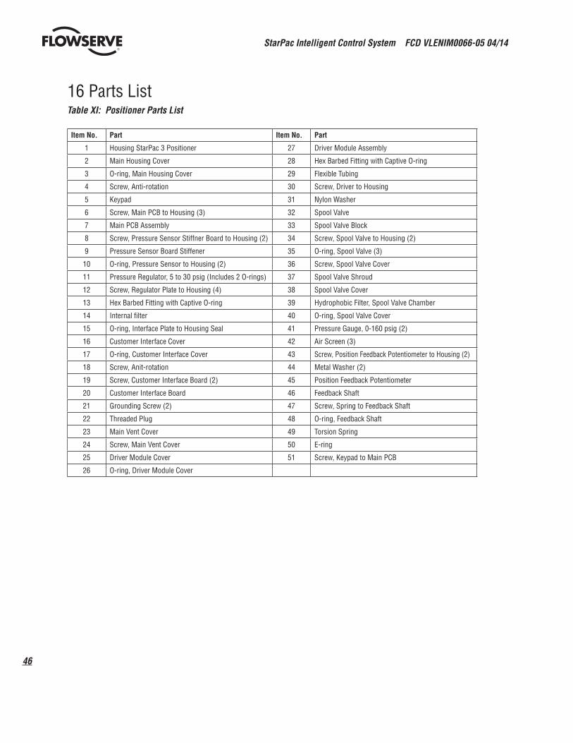
StarPac Intelligent Control System FCD VLENIM0066-05 04/14
46
®
16 Parts ListTable XI: Positioner Parts List
Item No. Part Item No. Part
1 Housing StarPac 3 Positioner 27 Driver Module Assembly
2 Main Housing Cover 28 Hex Barbed Fitting with Captive O-ring
3 O-ring, Main Housing Cover 29 Flexible Tubing
4 Screw, Anti-rotation 30 Screw, Driver to Housing
5 Keypad 31 Nylon Washer
6 Screw, Main PCB to Housing (3) 32 Spool Valve
7 Main PCB Assembly 33 Spool Valve Block
8 Screw, Pressure Sensor Stiffner Board to Housing (2) 34 Screw, Spool Valve to Housing (2)
9 Pressure Sensor Board Stiffener 35 O-ring, Spool Valve (3)
10 O-ring, Pressure Sensor to Housing (2) 36 Screw, Spool Valve Cover
11 Pressure Regulator, 5 to 30 psig (Includes 2 O-rings) 37 Spool Valve Shroud
12 Screw, Regulator Plate to Housing (4) 38 Spool Valve Cover
13 Hex Barbed Fitting with Captive O-ring 39 Hydrophobic Filter, Spool Valve Chamber
14 Internal filter 40 O-ring, Spool Valve Cover
15 O-ring, Interface Plate to Housing Seal 41 Pressure Gauge, 0-160 psig (2)
16 Customer Interface Cover 42 Air Screen (3)
17 O-ring, Customer Interface Cover 43 Screw, Position Feedback Potentiometer to Housing (2)
18 Screw, Anit-rotation 44 Metal Washer (2)
19 Screw, Customer Interface Board (2) 45 Position Feedback Potentiometer
20 Customer Interface Board 46 Feedback Shaft
21 Grounding Screw (2) 47 Screw, Spring to Feedback Shaft
22 Threaded Plug 48 O-ring, Feedback Shaft
23 Main Vent Cover 49 Torsion Spring
24 Screw, Main Vent Cover 50 E-ring
25 Driver Module Cover 51 Screw, Keypad to Main PCB
26 O-ring, Driver Module Cover

47
StarPac Intelligent Control System FCD VLENIM0066-05 04/14
flowserve.com
®
35
2
3
4
67
8
9
10
1112
13
14
15
1617 18
1920
21
22232425
26
27
28
29
30
31
32
3334
36
37
38
39
4041
4243
44
45
46
4748
49
50
51
1
5
Figure 24: Positioner Exploded View
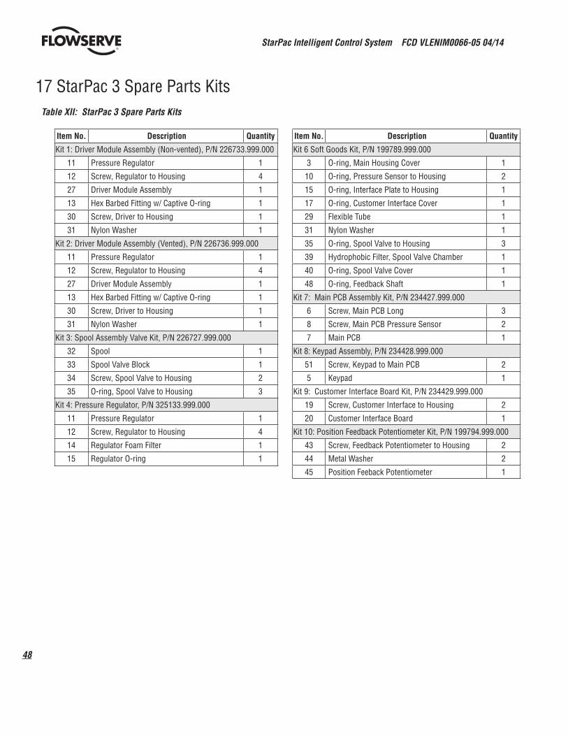
StarPac Intelligent Control System FCD VLENIM0066-05 04/14
48
®
17 StarPac 3 Spare Parts Kits
Item No. Description Quantity
Kit 1: Driver Module Assembly (Non-vented), P/N 226733.999.000
11 Pressure Regulator 1
12 Screw, Regulator to Housing 4
27 Driver Module Assembly 1
13 Hex Barbed Fitting w/ Captive O-ring 1
30 Screw, Driver to Housing 1
31 Nylon Washer 1
Kit 2: Driver Module Assembly (Vented), P/N 226736.999.000
11 Pressure Regulator 1
12 Screw, Regulator to Housing 4
27 Driver Module Assembly 1
13 Hex Barbed Fitting w/ Captive O-ring 1
30 Screw, Driver to Housing 1
31 Nylon Washer 1
Kit 3: Spool Assembly Valve Kit, P/N 226727.999.000
32 Spool 1
33 Spool Valve Block 1
34 Screw, Spool Valve to Housing 2
35 O-ring, Spool Valve to Housing 3
Kit 4: Pressure Regulator, P/N 325133.999.000
11 Pressure Regulator 1
12 Screw, Regulator to Housing 4
14 Regulator Foam Filter 1
15 Regulator O-ring 1
Item No. Description Quantity
Kit 6 Soft Goods Kit, P/N 199789.999.000
3 O-ring, Main Housing Cover 1
10 O-ring, Pressure Sensor to Housing 2
15 O-ring, Interface Plate to Housing 1
17 O-ring, Customer Interface Cover 1
29 Flexible Tube 1
31 Nylon Washer 1
35 O-ring, Spool Valve to Housing 3
39 Hydrophobic Filter, Spool Valve Chamber 1
40 O-ring, Spool Valve Cover 1
48 O-ring, Feedback Shaft 1
Kit 7: Main PCB Assembly Kit, P/N 234427.999.000
6 Screw, Main PCB Long 3
8 Screw, Main PCB Pressure Sensor 2
7 Main PCB 1
Kit 8: Keypad Assembly, P/N 234428.999.000
51 Screw, Keypad to Main PCB 2
5 Keypad 1
Kit 9: Customer Interface Board Kit, P/N 234429.999.000
19 Screw, Customer Interface to Housing 2
20 Customer Interface Board 1
Kit 10: Position Feedback Potentiometer Kit, P/N 199794.999.000
43 Screw, Feedback Potentiometer to Housing 2
44 Metal Washer 2
45 Position Feeback Potentiometer 1
Table XII: StarPac 3 Spare Parts Kits
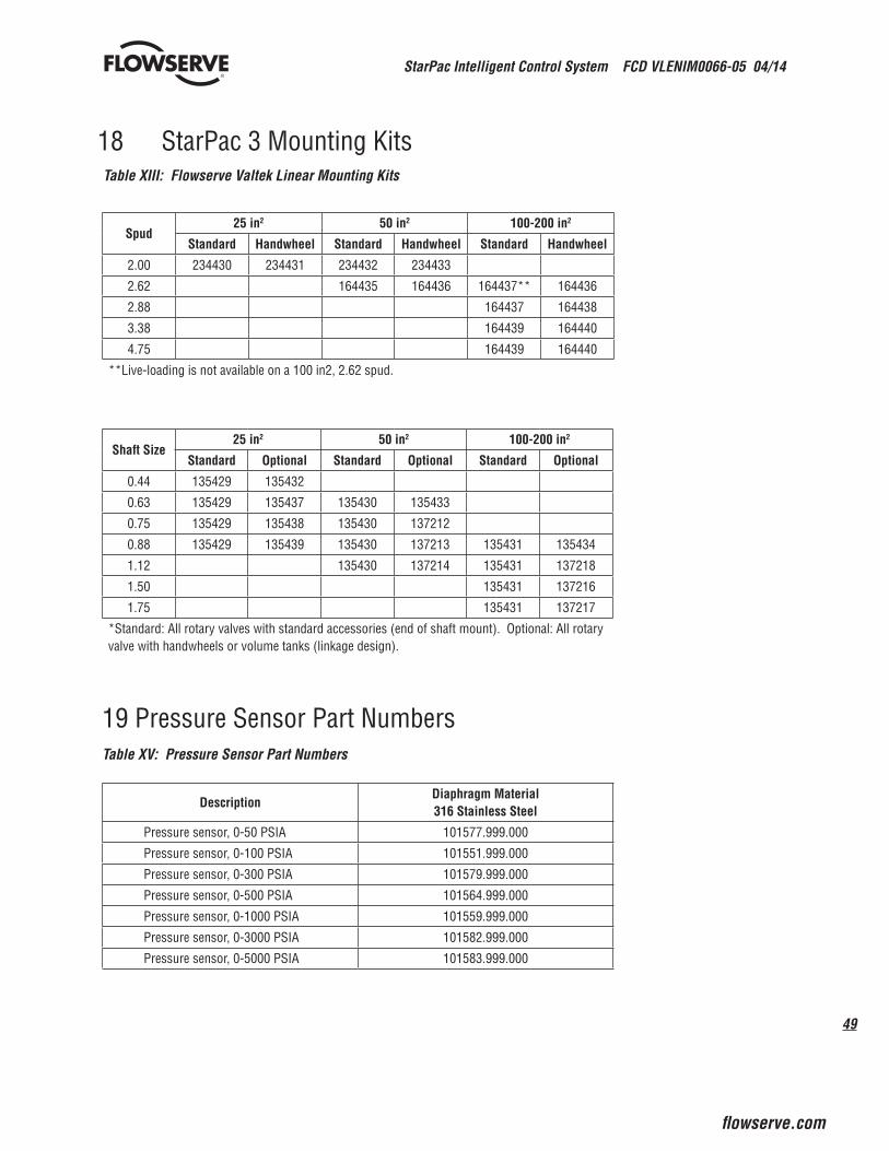
49
StarPac Intelligent Control System FCD VLENIM0066-05 04/14
flowserve.com
®
18 StarPac 3 Mounting KitsTable XIII: Flowserve Valtek Linear Mounting Kits
Spud25 in2 50 in2 100-200 in2
Standard Handwheel Standard Handwheel Standard Handwheel
2.00 234430 234431 234432 234433
2.62 164435 164436 164437** 164436
2.88 164437 164438
3.38 164439 164440
4.75 164439 164440
**Live-loading is not available on a 100 in2, 2.62 spud.
Shaft Size25 in2 50 in2 100-200 in2
Standard Optional Standard Optional Standard Optional
0.44 135429 135432
0.63 135429 135437 135430 135433
0.75 135429 135438 135430 137212
0.88 135429 135439 135430 137213 135431 135434
1.12 135430 137214 135431 137218
1.50 135431 137216
1.75 135431 137217
*Standard: All rotary valves with standard accessories (end of shaft mount). Optional: All rotary valve with handwheels or volume tanks (linkage design).
DescriptionDiaphragm Material316 Stainless Steel
Pressure sensor, 0-50 PSIA 101577.999.000
Pressure sensor, 0-100 PSIA 101551.999.000
Pressure sensor, 0-300 PSIA 101579.999.000
Pressure sensor, 0-500 PSIA 101564.999.000
Pressure sensor, 0-1000 PSIA 101559.999.000
Pressure sensor, 0-3000 PSIA 101582.999.000
Pressure sensor, 0-5000 PSIA 101583.999.000
19 Pressure Sensor Part NumbersTable XV: Pressure Sensor Part Numbers

StarPac Intelligent Control System FCD VLENIM0066-05 04/14
50
®
20 Pressure Sensor Spare Parts Kits
Table XVI: Pressure Sensor Gasket Kits (See Body Mount Sensor Configurations Drawing and Remote Sensor Configurati-
on for item numbers.
Note: Kits 1 thru 4 will service two body or two remote-mount pressure sensors from any one of the pressure sensor configuration drawing
numbers listed below each table.
Item No. Description Quantity
Kit 1 - Viton O-ring Replacement Kit, Part No. 134559.999.000
6 Environmental O-ring, Viton 2
8 Environmental O-ring, Viton 4
10 O-ring seal, Viton 2
20 Environmental O-ring, Viton 2
21 O-ring seal, Viton 2
Applies to Configuration Drawing Numbers: 83883, 83891, 83904, 83884, 83892, 101565, 83887 83900, 127586, 83888, 83901
Item No. Description Quantity
Kit 2 - Spiral Wound Gasket Replacement Kit, Part No. 134560.999.000
6 Environmental O-ring, Viton 2
8 Environmental O-ring, Viton 4
10 O-ring seal, Viton 2
20 Environmental O-ring, Viton 2
21 Spiral wound gasket seal 2
Applies to Configuration Drawing Numbers: 83938, 83890, 122670, 83886, 83903, 127563, 83899, 127632
Item No. Description Quantity
Kit 3 - Teflon Gasket Replacement Kit Part No. 134561.999.000
6 Environmental O-ring, Viton 2
8 Environmental O-ring, Viton 4
10 Teflon gasket seal 2
20 Environmental O-ring, Viton 2
21 Teflon™ gasket seal 2
Applies to Configuration Drawing Numbers: 122513, 127565
Item No. Description Quantity
Kit 4 - Kalrez O-ring Replacement Kit, Part No. 134562.999.000
6 Environmental O-ring, Viton 2
8 Environmental O-ring, Viton 4
10 O-ring seal, Kalrez™ 2
20 Environmental O-ring, Kalrez 2
21 O-ring seal, Kalrez 2
Configuration Drawing Numbers: 83885, 83889, 127665, 83893, 83902
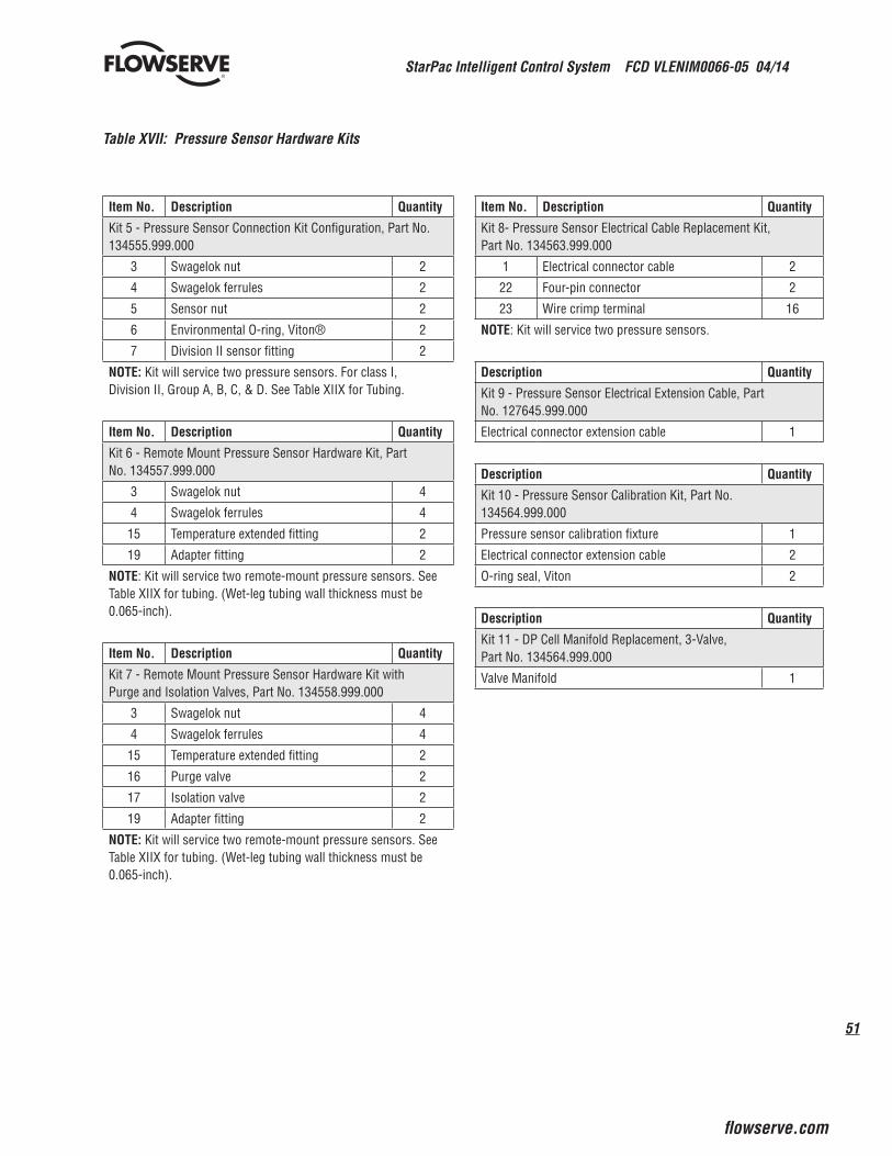
51
StarPac Intelligent Control System FCD VLENIM0066-05 04/14
flowserve.com
®
Table XVII: Pressure Sensor Hardware Kits
Item No. Description Quantity
Kit 5 - Pressure Sensor Connection Kit Configuration, Part No. 134555.999.000
3 Swagelok nut 2
4 Swagelok ferrules 2
5 Sensor nut 2
6 Environmental O-ring, Viton® 2
7 Division II sensor fitting 2
NOTE: Kit will service two pressure sensors. For class I, Division II, Group A, B, C, & D. See Table XIIX for Tubing.
Item No. Description Quantity
Kit 6 - Remote Mount Pressure Sensor Hardware Kit, Part No. 134557.999.000
3 Swagelok nut 4
4 Swagelok ferrules 4
15 Temperature extended fitting 2
19 Adapter fitting 2
NOTE: Kit will service two remote-mount pressure sensors. See Table XIIX for tubing. (Wet-leg tubing wall thickness must be 0.065-inch).
Item No. Description Quantity
Kit 7 - Remote Mount Pressure Sensor Hardware Kit with Purge and Isolation Valves, Part No. 134558.999.000
3 Swagelok nut 4
4 Swagelok ferrules 4
15 Temperature extended fitting 2
16 Purge valve 2
17 Isolation valve 2
19 Adapter fitting 2
NOTE: Kit will service two remote-mount pressure sensors. See Table XIIX for tubing. (Wet-leg tubing wall thickness must be 0.065-inch).
Item No. Description Quantity
Kit 8- Pressure Sensor Electrical Cable Replacement Kit, Part No. 134563.999.000
1 Electrical connector cable 2
22 Four-pin connector 2
23 Wire crimp terminal 16
NOTE: Kit will service two pressure sensors.
Description Quantity
Kit 9 - Pressure Sensor Electrical Extension Cable, Part No. 127645.999.000
Electrical connector extension cable 1
Description Quantity
Kit 10 - Pressure Sensor Calibration Kit, Part No. 134564.999.000
Pressure sensor calibration fixture 1
Electrical connector extension cable 2
O-ring seal, Viton 2
Description Quantity
Kit 11 - DP Cell Manifold Replacement, 3-Valve, Part No. 134564.999.000
Valve Manifold 1
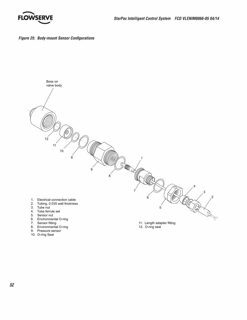
StarPac Intelligent Control System FCD VLENIM0066-05 04/14
52
®
Figure 25: Body-mount Sensor Configurations
Boss onvalve body
12
11
10
8
9
8
1
7
6
5
4
32
1. Electrical connection cable2. Tubing, 0.035 wall thickness3. Tube nut4. Tube ferrule set5. Sensor nut6. Environmental O-ring7. Sensor fitting8. Environmental O-ring9. Pressure sensor10. O-ring Seal
11. Length adapter fitting12. O-ring seal

53
StarPac Intelligent Control System FCD VLENIM0066-05 04/14
flowserve.com
®
Figure 26: Remote-mount Sensor Configurations
23
45
67
8
9
810
16
15
412
1121
20
19
43
18
3
4
17
43
18
1. Electrical connector cable2. Tubing 0.035-inch wall3. Tube nut4. Tube ferrule set5. Sensor nut6. Environmental O-ring7. Sensor fitting8. Environmental O-ring9. Pressure sensor10. O-ring seal11. Length adapter fitting12. O-ring seal
15. Temperature extended fitting16. Purge Valve17. Isolation valve18. Wet-leg tubing, 0.065-inch wall19. Adapter fitting20. Environmental O-ring21. O-ring seal
21 Temperature Sensor Spare Parts KitsTable XXVIII: Temperature Probe Kits (See temperature sensor configuration drawing for item numbers.)
Item No. Description Quantity
Kit 12 - Standard Temperature Probe Replacement,Configuration, Part No. 083855.999.000
2 Standard temperature probe 1
Item No. Description Quantity
Kit 13 - Through Hole Temperature Probe Replacement,Part No. 105646.999.000
2 Through hole temperature probe 1
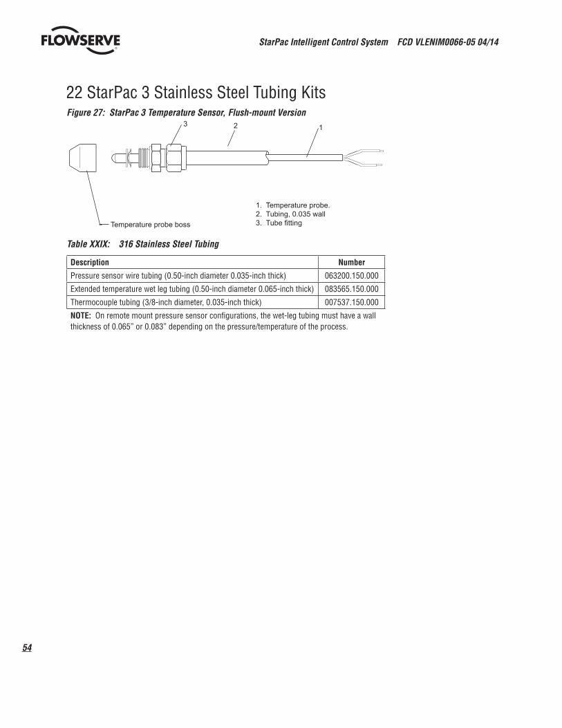
StarPac Intelligent Control System FCD VLENIM0066-05 04/14
54
®
22 StarPac 3 Stainless Steel Tubing KitsFigure 27: StarPac 3 Temperature Sensor, Flush-mount Version
Temperature probe boss
123
1. Temperature probe.2. Tubing, 0.035 wall3. Tube fitting
Table XXIX: 316 Stainless Steel Tubing
Description Number
Pressure sensor wire tubing (0.50-inch diameter 0.035-inch thick) 063200.150.000
Extended temperature wet leg tubing (0.50-inch diameter 0.065-inch thick) 083565.150.000
Thermocouple tubing (3/8-inch diameter, 0.035-inch thick) 007537.150.000
NOTE: On remote mount pressure sensor configurations, the wet-leg tubing must have a wall thickness of 0.065” or 0.083” depending on the pressure/temperature of the process.
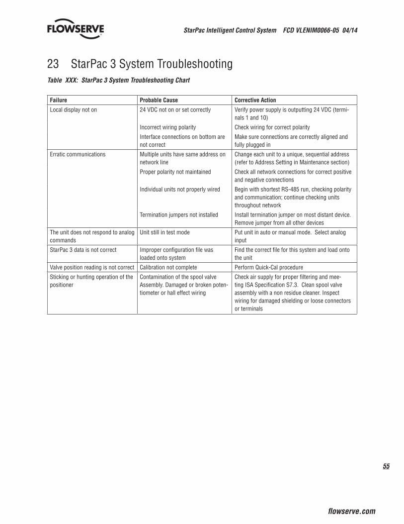
55
StarPac Intelligent Control System FCD VLENIM0066-05 04/14
flowserve.com
®
23 StarPac 3 System TroubleshootingTable XXX: StarPac 3 System Troubleshooting Chart
Failure Probable Cause Corrective Action
Local display not on 24 VDC not on or set correctly Verify power supply is outputting 24 VDC (termi-nals 1 and 10)
Incorrect wiring polarity Check wiring for correct polarity
Interface connections on bottom are not correct
Make sure connections are correctly aligned and fully plugged in
Erratic communications Multiple units have same address on network line
Change each unit to a unique, sequential address (refer to Address Setting in Maintenance section)
Proper polarity not maintained Check all network connections for correct positive and negative connections
Individual units not properly wired Begin with shortest RS-485 run, checking polarity and communication; continue checking units throughout network
Termination jumpers not installed Install termination jumper on most distant device. Remove jumper from all other devices
The unit does not respond to analog commands
Unit still in test mode Put unit in auto or manual mode. Select analog input
StarPac 3 data is not correct Improper configuration file was loaded onto system
Find the correct file for this system and load onto the unit
Valve position reading is not correct Calibration not complete Perform Quick-Cal procedure
Sticking or hunting operation of the positioner
Contamination of the spool valve Assembly. Damaged or broken poten-tiometer or hall effect wiring
Check air supply for proper filtering and mee-ting ISA Specification S7.3. Clean spool valve assembly with a non residue cleaner. Inspect wiring for damaged shielding or loose connectors or terminals
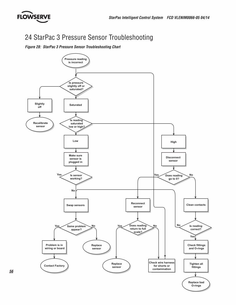
StarPac Intelligent Control System FCD VLENIM0066-05 04/14
56
®
24 StarPac 3 Pressure Sensor TroubleshootingFigure 28: StarPac 3 Pressure Sensor Troubleshooting Chart
Pressure readingis incorrect
Is pressureslightly off or saturated?
Saturated
Is reading saturated
low or high?
Low
Slightlyoff
Recalibratesensor
Make suresensor is
plugged in
Yes Is sensorworking?
No
Swap sensors
Yes NoSame problemappear?
Problem is in wiring or board
Contact Factory
Replacesensor
Replacesensor
Check wire harnessfor shorts or
contamination
Replace badO-rings
Tighten allfittings
Check fittingsand O-rings
Yes
Is readingcorrect?
NoYes NoDoes readingreturn to full
scale?
Reconnectsensor
Yes NoDoes readinggo to 0?
Disconnectsensor
High
Clean contacts
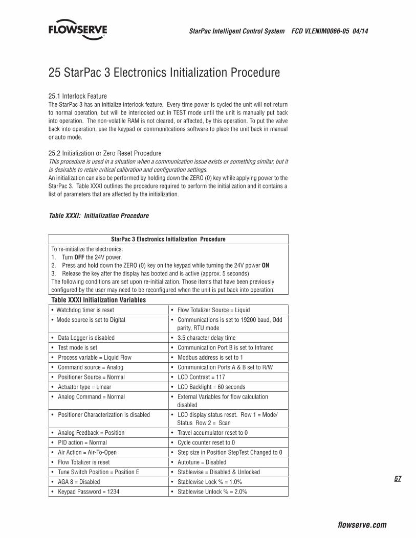
57
StarPac Intelligent Control System FCD VLENIM0066-05 04/14
flowserve.com
®
flowserve.com
25 StarPac 3 Electronics Initialization Procedure
25.1 Interlock FeatureThe StarPac 3 has an initialize interlock feature. Every time power is cycled the unit will not return to normal operation, but will be interlocked out in TEST mode until the unit is manually put back into operation. The non-volatile RAM is not cleared, or affected, by this operation. To put the valve back into operation, use the keypad or communitcations software to place the unit back in manual or auto mode.
25.2 Initialization or Zero Reset ProcedureThis procedure is used in a situation when a communication issue exists or something similar, but it is desirable to retain critical calibration and configuration settings.An initialization can also be performed by holding down the ZERO (0) key while applying power to the StarPac 3. Table XXXI outlines the procedure required to perform the initialization and it contains a list of parameters that are affected by the initialization.
Table XXXI: Initialization Procedure
StarPac 3 Electronics Initialization Procedure
To re-initialize the electronics:1. Turn OFF the 24V power.2. Press and hold down the ZERO (0) key on the keypad while turning the 24V power ON3. Release the key after the display has booted and is active (approx. 5 seconds)The following conditions are set upon re-initialization. Those items that have been previously configured by the user may need to be reconfigured when the unit is put back into operation:
Table XXXI Initialization Variables• Watchdog timer is reset • Flow Totalizer Source = Liquid
• Mode source is set to Digital • Communications is set to 19200 baud, Odd parity, RTU mode
• Data Logger is disabled • 3.5 character delay time
• Test mode is set • Communication Port B is set to Infrared
• Process variable = Liquid Flow • Modbus address is set to 1
• Command source = Analog • Communication Ports A & B set to R/W
• Positioner Source = Normal • LCD Contrast = 117
• Actuator type = Linear • LCD Backlight = 60 seconds
• Analog Command = Normal • External Variables for flow calculation disabled
• Positioner Characterization is disabled • LCD display status reset. Row 1 = Mode/ Status Row 2 = Scan
• Analog Feedback = Position • Travel accumulator reset to 0
• PID action = Normal • Cycle counter reset to 0
• Air Action = Air-To-Open • Step size in Position StepTest Changed to 0
• Flow Totalizer is reset • Autotune = Disabled
• Tune Switch Position = Position E • Stablewise = Disabled & Unlocked
• AGA 8 = Disabled • Stablewise Lock % = 1.0%
• Keypad Password = 1234 • Stablewise Unlock % = 2.0%
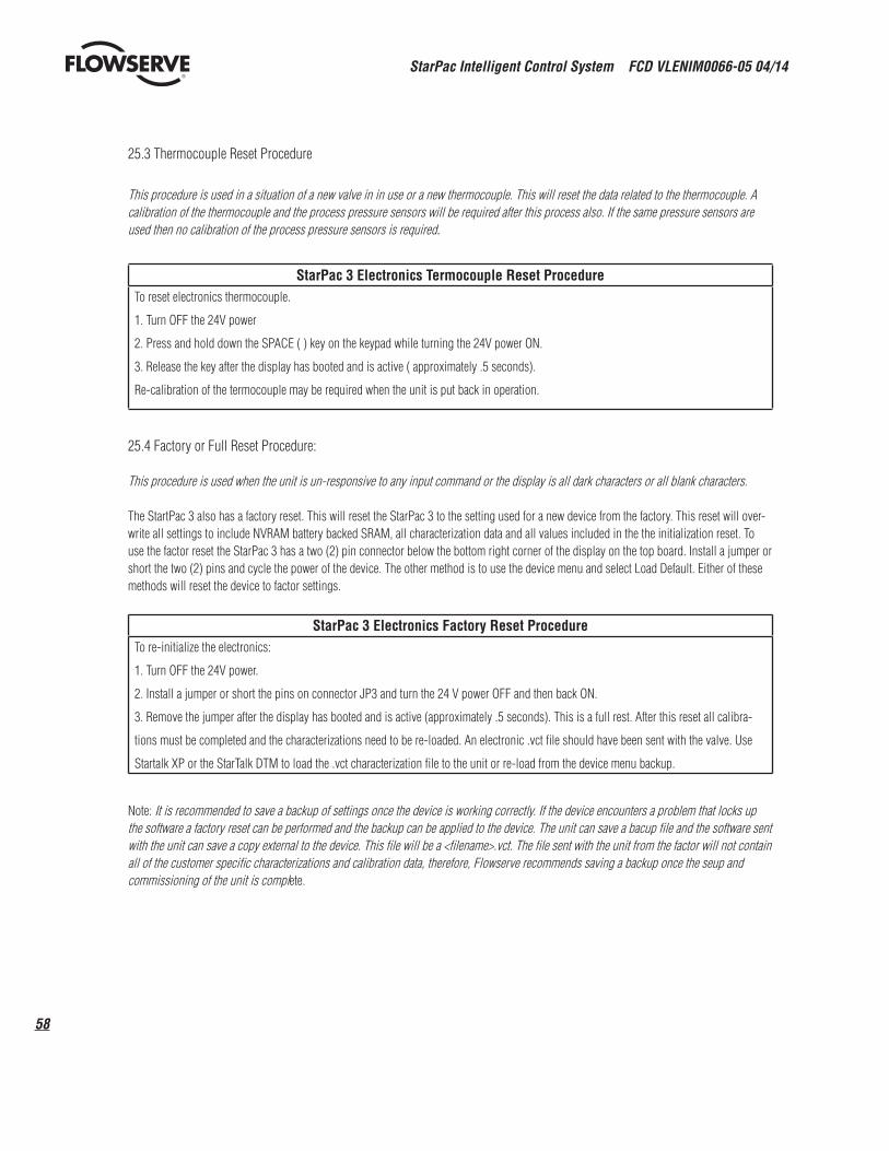
StarPac Intelligent Control System FCD VLENIM0066-05 04/14
58
®
25.3 Thermocouple Reset Procedure
This procedure is used in a situation of a new valve in in use or a new thermocouple. This will reset the data related to the thermocouple. A calibration of the thermocouple and the process pressure sensors will be required after this process also. If the same pressure sensors are used then no calibration of the process pressure sensors is required.
StarPac 3 Electronics Termocouple Reset ProcedureTo reset electronics thermocouple.
1. Turn OFF the 24V power
2. Press and hold down the SPACE ( ) key on the keypad while turning the 24V power ON.
3. Release the key after the display has booted and is active ( approximately .5 seconds).
Re-calibration of the termocouple may be required when the unit is put back in operation.
25.4 Factory or Full Reset Procedure:
This procedure is used when the unit is un-responsive to any input command or the display is all dark characters or all blank characters.
The StartPac 3 also has a factory reset. This will reset the StarPac 3 to the setting used for a new device from the factory. This reset will over-write all settings to include NVRAM battery backed SRAM, all characterization data and all values included in the the initialization reset. To use the factor reset the StarPac 3 has a two (2) pin connector below the bottom right corner of the display on the top board. Install a jumper or short the two (2) pins and cycle the power of the device. The other method is to use the device menu and select Load Default. Either of these methods will reset the device to factor settings.
StarPac 3 Electronics Factory Reset ProcedureTo re-initialize the electronics:
1. Turn OFF the 24V power.
2. Install a jumper or short the pins on connector JP3 and turn the 24 V power OFF and then back ON.
3. Remove the jumper after the display has booted and is active (approximately .5 seconds). This is a full rest. After this reset all calibra-
tions must be completed and the characterizations need to be re-loaded. An electronic .vct file should have been sent with the valve. Use
Startalk XP or the StarTalk DTM to load the .vct characterization file to the unit or re-load from the device menu backup.
Note: It is recommended to save a backup of settings once the device is working correctly. If the device encounters a problem that locks up the software a factory reset can be performed and the backup can be applied to the device. The unit can save a bacup file and the software sent with the unit can save a copy external to the device. This file will be a <filename>.vct. The file sent with the unit from the factor will not contain all of the customer specific characterizations and calibration data, therefore, Flowserve recommends saving a backup once the seup and commissioning of the unit is complete.
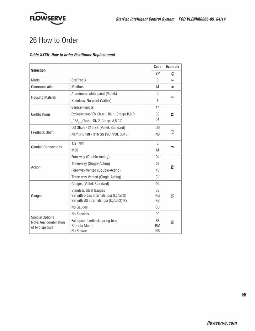
59
StarPac Intelligent Control System FCD VLENIM0066-05 04/14
flowserve.com
®
26 How to Order
Table XXXII: How to order Positioner Replacement
SelectionCode Example
SP
SPModel StarPac 3 3 3Communication Modbus M
M
Housing MaterialAluminum, white paint (Valtek) 0 0
Stainless, No paint (Valtek) 1
Certifications
General Purpose 14
14Explosionproof FM Class I, Div 1, Groups B,C,D
CCSAUSA Class I, Div 2, Groups A,B,C,D
3031
Feedback ShaftDD Shaft - 316 SS (Valtek Standard) D6 D6
Namur Shaft - 316 SS (VDI/VDE 3845) N6
Conduit Connections1/2˝ NPT E E
M20 M
Action
Four-way (Double-Acting) 04
04
Three-way (Single-Acting) 03
Four-way Vented (Double-Acting) 4V
Three-way Vented (Single-Acting) 3V
Gauges
Gauges (Valtek Standard) 0G
0G
Stainless Steel GaugesSS with brass internals, psi (kg/cm2)SS with SS internals, psi (kg/cm2) KS
0SKGKS
No Gauges 0U
Special OptionsNote: Any combination of two specials
No Specials 00
00Fail open, feedback spring biasRemote MountNo Sensor
SFRMNS
StarPac Intelligent Control System FCD VLENIM0066-05 04/14
60
®
To find your local Flowserve representative:
For more information about Flowserve Corporation, visit www.flowserve.com or call USA 1 800 225 6989
FCD VLENIM0066-05 04/14 Printed in USA.
flowserve.com
Flowserve Headquarters5215 N. O’Connor Blvd., Suite 2300 Irving, TX 75039Telephone: 972 443 6500
Control Valve Manufacturing1350 Mountain Springs ParkwaySpringville, UT 84663-3004 USATelephone: 1 801 489 8611Fax: 1 801 489 3719
Singapore12 Tuas Ave. 20, 638824Republic of SingaporeTelephone: +65 862 3332Fax: +65 862 4940
AustriaKasernengasse 6Villach Austria 9500Telephone: +43 0 4242 41181 0Fax: +43 0 4242 41181 50
Australia14 Dalmore Dr.Scoresby, Victoria, Australia 3179Telephone: +61 3 9759 3300Fax: +61 3 9759 3301
China585, Hanwei Plaza7 Guanghua RoadBeijing, China 100004Telephone: +86 10 6561 1900
Flowserve Corporation has established industry leadership in the design and manufacture of its products. When properly selected, this Flowserve product is designed to perform its intended function safely during its useful life. However, the purchaser or user of Flowserve products should be aware that Flowserve products might be used in numerous applications under a wide variety of industrial service conditions. Although Flowserve can (and often does) provide general guidelines, it cannot provide specific data and warnings for all possible applications. The purchaser/user must therefore assume the ultimate responsibility for the proper sizing and selection, installation, operation and maintenance of Flowserve products. The purchaser/user should read and understand the Installation Operation Maintenance (IOM) instructions included with the product, and train its employees and contractors in the safe use of Flowserve products in connection with the specific application.
While the information and specifications contained in this literature are believed to be accurate, they are supplied for informa-tive purposes only and should not be considered certified or as a guarantee of satisfactory results by reliance thereon. Nothing contained herein is to be construed as a warranty or guarantee, express or implied, regarding any matter with respect to this product. Because Flowserve is continually improving and upgrading its product design, the specifications, dimensions and information contained herein are subject to change without notice. Should any question arise concerning these provisions, the purchaser/user should contact Flowserve Corporation at any one of its worldwide operations or offices.
© 2009 Flowserve Corporation, Irving, Texas, USA. Flowserve is a registered trademark of Flowserve Corporation.