user manual for autotrack
TRANSCRIPT

User Manual for
AutoTrack
Advanced Vehicle Swept Path Analysis


Licence agreement
This software is the property of Savoy Computing Services Limited.It may be used only under the terms of the Licence Agreement.
Disclaimer
No warranty is given as to the results or performance of this Software.
The User is responsible for satisfying himself that the Software is suitable for his purpose and performs in accordance with the claims in the User Manual.
It is assumed that the User is a competent practitioner who is experienced in the theories and techniques upon which the Software is based.
Copyright notice
This software is the copyright of Savoy Computing Services Limited.© Savoy Computing Services Limited (1991-2010)AutoCAD is a registered trademark of Autodesk, Inc.MicroStation 95, MicroStation SE, MicroStation /J, MicroStation V8 & MicroStation XM are trademarks of Bentley Systems Incorporated.
Savoy Computing Services LimitedClermont HouseHigh StreetCranbrookKentTN17 3DNEngland
Tel : +44 (0)1580 720 011Fax : +44 (0)1580 720 022US: 1-866 527 3790Eml: [email protected]: http://www.savoy.co.uk
May 10

User Manual for AutoTrack Contents v
Contents
Installing AutoTrack 1
AutoTrack hardware lock ..............................................................................................1Authorisation code ........................................................................................................2Licences ........................................................................................................................2
Single user licences .........................................................................................2Network licences ..............................................................................................2Trial copies .......................................................................................................2Demonstration copies ......................................................................................2
Installing the software ...................................................................................................3Single user version...........................................................................................3Network version ...............................................................................................4
Installing the NetHASP Licence Manager software (Network version only) .................5Installing the licence manager on a Windows NT/2000/XP server ..................5Installing the licence manager on a Novell Netware server...........................10
Moving the NetHASP Licence Manager (Network version only) ................................10Installing the NetHASP Licence Monitor software (Network version only) .................11
Installing the licence monitor on a Windows NT/2000/xp client computer.....11Installing AutoTrack.....................................................................................................14
Some final points to note................................................................................26Modifying, repairing or removing AutoTrack ...............................................................28Installing AutoTrack from the web...............................................................................31
To install the software ....................................................................................31To extract the software...................................................................................31
AutoCAD object enabler..............................................................................................32To install the object enabler version from CD................................................32To install the software from the web ..............................................................32
Scripted 'silent' installations ........................................................................................33Creating the install script................................................................................33Running a silent install ...................................................................................34Adding files to an installation .........................................................................35Uninstalling AutoTrack ...................................................................................35Updating AutoTrack .......................................................................................35
Configuring AutoCAD manually ..................................................................................36Configuring MicroStation, Bentley PowerDraft, Bentley PowerCivil or Bentley MX manually ......................................................................................................................38Resolving hardware lock problems .............................................................................40
Running the Licence Manager on the same computer as AutoTrack............40Running the Licence Manager on a remote computer...................................41Identifying and resolving problems ................................................................41
Technical Support .......................................................................................................42
Starting AutoTrack 43
Running stand-alone AutoTrack .................................................................................43Welcome dialog
(1700)...................................................................................................44
Demonstration Version dialog (1800)
.............................................................................45Rental Version dialog
(1820)..........................................................................................46
Transfer Rental Licence dialog (1850)
..............................................................47Retrieve Rental Licence dialog
(1840)..............................................................47
Running AutoTrack in AutoCAD .................................................................................48

vi Contents User Manual for AutoTrack
To run AutoTrack from the Taskbar Start Programs Menu............................48To run AutoTrack from within AutoCAD.........................................................48To load and run AutoTrack for AutoCAD manually........................................50Viewing AutoTrack paths in AutoCAD if you don’t have AutoTrack ..............52
Running AutoTrack in MicroStation ............................................................................53To run AutoTrack from the Taskbar Start Programs menu…........................53To run AutoTrack from within MicroStation… ................................................54To load and run AutoTrack for MicroStation manually…...............................55
The New Features dialog (1975)
....................................................................................56The Getting Started dialog (not AutoTrack Templates)
(1900)......................................57
A few do's and don'ts ..................................................................................................58
Introduction 59
What AutoTrack can and can’t do...............................................................................59Capabilities.....................................................................................................59Features .........................................................................................................59Limitations ......................................................................................................59
Migrating from WinTrack .............................................................................................60Reading pre-v5 AutoTrack libraries ............................................................................60How to use AutoTrack.................................................................................................60
Settings ..........................................................................................................61Modelling rigid vehicles ..................................................................................61Modelling articulated semi-trailer vehicles .....................................................61Modelling drawbar and multi-trailer vehicles..................................................61Modelling aircraft............................................................................................62Modelling combination steered vehicles ........................................................62Modelling vehicles with pushing tractors........................................................62Modelling vehicles with steerable couplings ..................................................62Modelling Active Hitches ................................................................................62Development & planning scenarios ...............................................................62Modelling the effects of super elevation and side friction ..............................63Modelling trams and light rail vehicles ...........................................................63Modelling conveyor systems..........................................................................63Fastest line through roundabouts ..................................................................63Checking vertical clearances .........................................................................63
What’s new in version 8? ............................................................................................64Manual layout ..............................................................................................................71
Notation conventions......................................................................................71Mouse conventions ........................................................................................71Default values ................................................................................................71
Getting help .................................................................................................................71Context sensitive on-line help ........................................................................72On-line assistance..........................................................................................72Help tutor........................................................................................................72Video tutorial ..................................................................................................72
Settings 73
Settings Wizard ...........................................................................................................73Settings Wizard: Scale
(2400)...........................................................................74
Settings Wizard: Editing Units (2410)
................................................................75Settings Wizard: Layers
(2420).........................................................................76
Settings Wizard: Turn Transitions (2440)
..........................................................77Settings Wizard: Design Speed
(2430).............................................................78
Settings Wizard: Steering Limits (2450)
............................................................79Settings Wizard: Articulation Limits
(2455)........................................................80
Settings Wizard: Dynamics (2460)
....................................................................81Settings Wizard: Updates
(2470).......................................................................82
Settings Wizard: Finish (2480)
...........................................................................83Report Wizard .............................................................................................................84

User Manual for AutoTrack Contents vii
Report Wizard: Start (3700)
...............................................................................85Report Wizard: Graphical sub-reports
(3710)....................................................86
Report Wizard: Path Annotation (3790)
.............................................................87Report Wizard: Profile
(3805)............................................................................88
Report Wizard: Steering & Articulation Graph (3795)
.......................................89Report Wizard: Construction Lines
(3800)........................................................90
Report Attributes dialog (3820)
..........................................................................91Attributes dialog
(3830)......................................................................................91
Report Wizard: Finish (3810)
.............................................................................92System Settings ..........................................................................................................93
System Settings: Start Up (2000)
......................................................................94System Settings: Directories
(2200)..................................................................96
System Settings: AutoLoad (2005)
....................................................................97System Settings: Language
(2010)...................................................................99
System Settings: Network (2015)
....................................................................100System Settings: Internet
(2210).....................................................................102
System Settings: Updates (2190)
....................................................................103System Settings: View
(2040)..........................................................................105
System Settings: Skill Level (2050)
.................................................................107System Settings: Paths: AutoDrive (Roads only)
(2100).................................108
System Settings: Paths: Manual Drive (Roads only) (2110)
...........................110System Settings: Paths: Follow Drive (Roads only)
(2120).............................112
System Settings: Paths: Guided Drive (Rail only) (2130)
................................114Drawing Settings .......................................................................................................115
Drawing Settings: Units (2020)
........................................................................116Drawing Settings: Scale
(2030).......................................................................117
Drawing Settings: Paths: Layers (AutoCAD only) (2060)
................................118Drawing Settings: Paths: Levels (MicroStation v8 onwards)
(2067)...............119
Drawing Settings: Paths: Levels (MicroStation pre-v8 only) (2065)
................120Layer / Level naming conventions ...............................................................121Drawing Settings: Paths: Tracking Point (Roads & Airports)
(2170)...............123
Drawing Settings: Paths: Model (Roads & Airports) (2070)
............................125Drawing Settings: Paths: Speed (Roads, Rail & Airports)
(2080)...................127
Drawing Settings: Paths: Transitions (Roads & Airports) (2085)
....................128Drawing Settings: Dynamics (Roads & Airports)
(2180).................................130
Drawing Settings: Paths: Reports (3000)
........................................................132Drawing Settings: Paths: Construction Lines
(3160).......................................133
Drawing Settings: Paths: Reports: Discrete (3020)
.........................................135Drawing Settings: Paths: Reports: Spaced
(3030)..........................................137
Drawing Settings: Paths: Reports: Loci (3040)
................................................139Drawing Settings: Paths: Reports: Envelope
(3050).......................................141
Drawing Settings: Paths: Reports: Offset Envelope 1 .................................143Drawing Settings: Paths: Reports: Profile
(3060)............................................145
Drawing Settings: Paths: Reports: Graph (3070)
............................................147Drawing Settings: Paths: Animations (not Roads)
(2150)...............................149
Templates 151
Generating turn templates.........................................................................................151To generate a turn template.........................................................................151
The Template Wizard................................................................................................151Template Wizard: Type
(6500)........................................................................152
Template Wizard: Vehicle (6510)
....................................................................153Template Wizard: Model Settings
(6515)........................................................154
Template Wizard: Turn Angles (6520)
.............................................................155Template Wizard: Format
(6530).....................................................................156
Swept Paths: Creating paths 157
AutoDrive (Roads only) .............................................................................................158To use AutoDrive in Arc mode .....................................................................158

viii Contents User Manual for AutoTrack
To drive forwards on an arc .........................................................................159To drive backwards on an arc......................................................................159To use AutoDrive in Bearing mode ..............................................................159AutoDrive options
(5110).................................................................................161
Manual Drive (not Rail) .............................................................................................165To use Manual Drive ....................................................................................165To start driving (Control Overlay)
(6020).........................................................166
To pause driving...........................................................................................167To adjust the view ........................................................................................167To undo part of the path...............................................................................168To redraw the path and update the reports .................................................168To show or hide the vehicle trail ..................................................................168To edit the path properties ...........................................................................168To edit the path reports ................................................................................168To terminate the current path.......................................................................168
Follow (not Rail) ........................................................................................................169To use Follow...............................................................................................169
Script (not Rail) .........................................................................................................171To create or edit an AutoTrack script
(6050)...................................................171
To run an AutoTrack script...........................................................................172To save an AutoTrack script ........................................................................172To load an AutoTrack script .........................................................................172AutoTrack script commands ........................................................................172
Guided Drive (Rail only) ............................................................................................176To use Guided Drive ....................................................................................176
Vertical Clearance.....................................................................................................178To use Vertical Clearance............................................................................178
Park a Vehicle ...........................................................................................................180To use Park a Vehicle ..................................................................................180
Selecting a vehicle to drive .......................................................................................181To open a vehicle library..............................................................................182To select a vehicle from a loaded library .....................................................182To close a vehicle library..............................................................................182To set a default vehicle ................................................................................182Default Vehicle dialog
(5100)...........................................................................183
Scale dialog (5130)
..........................................................................................183Changing your vehicle...............................................................................................184
To change the selected vehicle ...................................................................184Positioning a vehicle interactively .............................................................................185
To change the position of the vehicle ..........................................................185To change the heading of the vehicle ..........................................................185To adjust the articulation ..............................................................................185
Positioning a vehicle (Position Vehicle dialog) (6000)
..................................................186To set or change the position of the vehicle ................................................186To set or change the heading of the entire vehicle......................................186To set or change the starting steering angle ...............................................186To set or change the starting orientation of a selected spine ......................186To position the vehicle at the start of an existing path.................................187To position the vehicle at the end of an existing path..................................187To position the vehicle at a point on an existing path ..................................187To view the path properties..........................................................................187To view the model settings ..........................................................................187To undo the last operation ...........................................................................187To start driving .............................................................................................187To adjust the view ........................................................................................187
Adjusting the view (View toolbar) ..............................................................................188To reset any drawing rotation ......................................................................188To rotate the drawing to the left ...................................................................188To rotate the drawing to the right .................................................................188To rotate the drawing automatically .............................................................188

User Manual for AutoTrack Contents ix
To pan the image (e.g. if the vehicle is close to the edge of the window) ...188To zoom in ...................................................................................................188To zoom out .................................................................................................188To show only the vehicle body.....................................................................189To show only the vehicle chassis.................................................................189To show both the vehicle body and chassis ................................................189
Swept Paths: Editing paths 191
Adjusting the path alignment (Path toolbar)..............................................................191To see the target points on the path ............................................................191To see the steering pointer ..........................................................................192To adjust the vehicle start position (not Rail) ...............................................192To adjust the vehicle start heading (not Rail)...............................................192To adjust the vehicle start steering angle (not Rail)....................................192To adjust the vehicle start spine angles (not Rail) ......................................192To move the path .........................................................................................192To rotate the path.........................................................................................193To copy the path ..........................................................................................193To explode the path entity (or cell)...............................................................193To delete a path ...........................................................................................193To trim the start of the path..........................................................................193To trim the end of the path ...........................................................................194To move target points (not Rail)...................................................................194To insert a new target point (not Rail) ..........................................................194To remove intermediate target points (not Rail) ..........................................195To delete the last target point (not Rail).......................................................195
Adjusting the path alignment using grip editing ........................................................195To enter grip editing mode ...........................................................................195To see the target points on a path ...............................................................196To see the steering pointer ..........................................................................196To adjust the vehicle start heading (not Rail)...............................................196To adjust the vehicle start steering angle (not Rail).....................................196To adjust the vehicle start spine angles (not Rail) ......................................197To move a path ............................................................................................197To move a target point (not Rail) .................................................................197To stretch a section in a path (not Rail) .......................................................197To adjust a bearing turn (not Rail) ...............................................................198To insert a new target point (not Rail) ..........................................................198To remove a target point (not Rail) ..............................................................198To trim the start of the path..........................................................................198To trim the end of the path ...........................................................................199
Undriveable Paths (5050)
.............................................................................................200Extending or trimming a path ....................................................................................201
To extend a path ..........................................................................................201To trim the start of the path..........................................................................201To trim the end of the path ...........................................................................201
Editing path properties (Path Properties dialog) .......................................................202Path Properties: Path Notes
(5010).................................................................203
Path Properties: Vehicle...............................................................................203Path Properties: Manoeuvres
(5020)...............................................................204
Path Properties: Reports..............................................................................206Adjusting model settings (Roads only)......................................................................206
To change the absolute steering limits ........................................................206To change the absolute articulation limits....................................................207
Adjusting speed settings ...........................................................................................207To change the design speed........................................................................207
Adjusting transition settings (not Rail).......................................................................207To change the turn transiton types ..............................................................207
Adjusting the tracking point (not Rail) .......................................................................208
x Contents User Manual for AutoTrack
To change the tracking point........................................................................208Adjusting dynamics settings (not Rail) ......................................................................209
To change dynamics settings ......................................................................209Vehicle details report.................................................................................................209
To insert a vehicle details report ..................................................................209To move a vehicle details report ..................................................................209To remove a vehicle details report ...............................................................209
Placing discrete body outlines (5140)
...........................................................................210To place discrete outlines ............................................................................210
Extracting path data ..................................................................................................211To extract path data .....................................................................................211Reading extracted data in Excel ..................................................................211
Swept Paths: Creating and editing vehicles 213
AutoTrack vehicle libraries ........................................................................................213Access to vehicle libraries............................................................................213Access to vehicles in the Pool .....................................................................214
Compatibility with previous versions .........................................................................214Loading AutoTrack 2.x vehicle libraries .......................................................214
Viewing a vehicle in a library or the pool (Library Explorer dialog) (3510)
...................215Finding vehicles online (Online Vehicle Library Explorer)
3580..................................217
Customising the Library Explorer view (Library Explorer Columns dialog) (3515)
.......218Vehicle Diagram dialog
(3570).....................................................................................219
Creating a new library (Library Details dialog) (3520)
..................................................221Library Details: Library .................................................................................221Library Details: Users
(3530)...........................................................................221
Saving a library .........................................................................................................223Sharing a library (Share Data dialog)
(3590)................................................................224
Printing library or vehicle details (Print dialog) (5070)
..................................................224Copying vehicles and units using drag and drop ......................................................225Building vehicles using drag and drop ......................................................................225Unlocking a library (Unlock Library dialog)
(3550)........................................................226
Creating a new group................................................................................................226Vehicle Group dialog
(4040).........................................................................................227
Viewing a vehicle used on a particular path..............................................................227Viewing or editing an existing vehicle .......................................................................227Creating vehicles.......................................................................................................228
To create a new vehicle ...............................................................................228The Vehicle Wizard ...................................................................................................229
Some tips for defining trams (Rail only) .......................................................229Vehicle wizard: Name
(7000)...........................................................................230
Vehicle wizard: Axles (7010)
...........................................................................231Vehicle wizard: Wheelbase
(7020)..................................................................232
Vehicle wizard: Drawbar (7050)
.......................................................................233Vehicle wizard: Steering (not Rail)
(7030).......................................................234
Vehicle wizard: Manoeuvrability (7040)
...........................................................235Vehicle wizard: Couplings
(7060)....................................................................236
Vehicle wizard: Body (7070)
............................................................................237Vehicle wizard: Tractor body
(7075)................................................................238
Vehicle wizard: Tram body (trams only) (7080)
...............................................239Vehicle wizard: Aircraft wings (aircraft only)
(7090)........................................240
Vehicle wizard: Aircraft Tailplane (aircraft only) (7100)
...................................241Vehicle wizard: Aircraft Fuselage (aircraft only)
(7110)...................................242
Vehicle wizard: Pantograph (trams only) (7120)
.............................................243Vehicle wizard: Finish
(7130)...........................................................................244
The Advanced Editor.................................................................................................245Vehicle Details dialog
(4050)........................................................................................245
Unit Details dialog (4060)
.............................................................................................246Unit Details: Unit ..........................................................................................247

User Manual for AutoTrack Contents xi
Unit Details: Front Axles / Rear Axles (4070)
..................................................249Unit Details: Steering
(4150)............................................................................256
Unit Details: Body / Outlines (4120)
................................................................258Unit Details: Couplings
(4140).........................................................................269
Units Details: Doors (Aircraft only) (4125)
.......................................................270Unit Details: Servicing (Aircraft only)
(4125)....................................................271
Parking: Creating and editing parking areas 273
Placing rows of bays .................................................................................................273To place a row of bays freehand..................................................................273To place a parallel row of bays ....................................................................274Unique parking standard names (Parking Standard Name dialog) .............275
Placing access roads (4430)
........................................................................................275To place an access road freehand...............................................................275To place an access road on a line ...............................................................276
Parking Report (4410)
..................................................................................................277To display the parking report .......................................................................277To customise the parking report ..................................................................277To export a parking report............................................................................278
Editing rows (Parking Row Properties dialog) (4450)
...................................................278To edit a parking row....................................................................................278
Editing individual bays (Parking Bay Properties dialog) (4440)
....................................280To edit a parking bay....................................................................................280
Editing islands (Parking Island Properties dialog) (4460)
.............................................281To edit a parking island ................................................................................281
Editing parking row layout .........................................................................................282To move a row of bays.................................................................................282To rotate a row of bays ................................................................................282To copy a row of bays ..................................................................................282To explode a row of bays .............................................................................282To delete a row of bays................................................................................283To join two rows of parking bays..................................................................283To extend a row of parking bays..................................................................283To add a vertex to a row of parking bays.....................................................283To adjust a parking row................................................................................283
Parking: Creating and editing standards 285
AutoTrack parking standards ....................................................................................285Access to parking standards........................................................................285Access to parking standards in the Pool......................................................286
Viewing a standard in a parking standard file or the pool (Parking Standard Explorer dialog)
(4400).................................................................................................286
Creating a new parking standard file (Parking Standard File dialog)........................287Parking Standard File: Parking Standard File..............................................287Parking Standard File: Users .......................................................................287
Saving a parking standard file...................................................................................289Sharing a parking standard (Share Data dialog) ......................................................289Copying standards and units using drag and drop ...................................................290Unlocking a parking standard file (Unlock Parking Standard File dialog)
(3555).........290
Creating a new group................................................................................................291Parking Standard Group dialog
(4670).........................................................................291
Selecting a Parking Standard....................................................................................292To set a default parking standard ................................................................292Default Parking Standard dialog
(4690)..........................................................292
Viewing or editing parking standards ........................................................................293To edit a parking standard ...........................................................................293Parking Standard: General
(4500)...................................................................294
Parking Standard: End Islands (4480)
.............................................................295Parking Standard: Bend Islands
(4470)...........................................................296

xii Contents User Manual for AutoTrack
Parking Standard: In Bay Numbering (4510)
...................................................297Parking Standard: Kerbside Bay Numbering
(4520).......................................298
Parking Standard: Vehicle Classes (4640)
......................................................299Parking Standard: Service Types
(4570).........................................................300
Parking Standard: Valid Bay Angles (4630)
....................................................301Parking Standard: Bay Dimensions
(4600).....................................................302
Parking Standard: Parking Meters (4530)
.......................................................303Parking Standard: Bay Markings
(4580)..........................................................304
Parking Standard: Bay Symbols (4620)
..........................................................306Parking Standard: Safety Zones
(4560)..........................................................308
Parking Standard: Bay Styles (4610)
..............................................................310Parking Standard: Safety Posts
(4550)...........................................................312
Parking Standard: Privacy Posts (4540)
..........................................................313Parking Standard: Wheel Stops
(4650)...........................................................314
Parking Standard: Construction Lines (4490)
..................................................315Attributes dialog ...........................................................................................316
Review 317
Properties ..................................................................................................................317Drawing Explorer
(3300)...............................................................................................317
Simple animations (Basic Animation dialog) (8000)
.....................................................320Advanced animation options (Advanced Animation dialog)
(8005)..............................321
Path Animation dialog (8020)
..........................................................................322Animation Commands dialog
(8040)...............................................................323
Animations dialog (8010)
.................................................................................3253D Animations (AutoCAD & MicroStation only) ........................................................325Fly-By Camera control (AutoCAD & MicroStation only)
(8060)....................................326
Recording an animation as an AVI file (8050)
..............................................................327Audit ..........................................................................................................................329
Audit dialog (8210)
...........................................................................................329Audit dialog: Exception Details
(8200).............................................................330
Print Audit Options dialog (8220)
.....................................................................331
Managing AutoTrack data 331
Exporting AutoTrack data (Export AutoTrack Data dialog) (5090)
...............................331Importing AutoTrack data (Import AutoTrack Data dialog)
(5080)...............................333
Using Export / Import for personal settings...............................................................333Drawing file size ........................................................................................................334
Recovering space in AutoCAD drawings .....................................................334Recovering space in MicroStation drawings ................................................334
Repair AutoTrack data ..............................................................................................334Purging AutoTrack data (Purge AutoTrack dialog)
(5060)...........................................334
Glossary of Terms 337
Index 347

User Manual for AutoTrack Installing AutoTrack 1
Installing AutoTrack
Although installation of AutoTrack is relatively easy we nevertheless recommend that it be undertaken only by suitably competent persons.
AutoTrack hardware lockAutoTrack is protected from illegal use by a hardware lock or hardware lock, a small device that must be plugged into either the parallel port or the USB port of your computer (or, in the case of network licences, file server). Without this device AutoTrack will not run.
Parallel hardware locks
The parallel port hardware lock may be connected at either end of a parallel printer cable but must be located between the computer and the printer (or plotter, T-switch, buffer etc.). Since the hardware lock will not affect the operation of the parallel port it can be left installed when AutoTrack is not in use.
Whenever possible printers or plotters that are plugged into the same parallel port as the AutoTrack hardware lock should be switched on before the program is used and left on throughout its use.
Up to four Savoy and third party hardware locks, as well as a printer, can be plugged into the same parallel port. However, users should note that whilst all Savoy program hardware locks are compatible with one another, third party hardware locks may cause problems. Such problems can usually be resolved by rearranging the order in which the hardware locks are chained or by plugging them in different ports.
USB hardware locks
USB hardware locks are becoming the norm with the gradual phasing out of the parallel port. There are fewer problems with USB dongles since they cannot be stacked.
Important Replacement Savoy hardware locks will only be issued to holders of current support and maintenance contracts on return of a damaged hardware lock. If the damaged hardware lock cannot be produced a replacement copy of AutoTrack will have to be purchased.

Authorisation codeIn addition to the hardware lock you will be required to enable your copy of AutoTrack by entering an Authorisation Code. The Authorisation Code changes each time the software is updated so if you download an AutoTrack update from the web you will need to contact Savoy for a new code.
LicencesDepending upon your licence you may be able to run AutoTrack on more than one computer.
Single user licences
You may install the software on as many machines as you wish but will only be able to run it on computers running Windows 98, ME, NT, 2000 or XP with an AutoTrack hardware lock plugged into the parallel or USB port.
Network licences
You may install the software on as many machines as you wish but will only be able to run it on computers running Windows 98, ME, NT, 2000 or XP that have a network link to the server that has the hardware lock plugged into its parallel or USB port.
Trial copies
Trial copies of AutoTrack may be issued with a licence that has a limited life. Once the licence expires the protection system will prevent the program from operating.
To convert an evaluation copy to the full version or to extend the evaluation period, the software will need to be relicensed. Relicensing involves issuing a new hardware lock or authorisation code.
Demonstration copies
Demonstration copies do not require a hardware lock because they distort the vehicles randomly thereby rendering them useless for real work. You may install demo copies on as many computers as you wish.

User Manual for AutoTrack Installing AutoTrack 3
Installing the softwareAutoTrack can be installed with either a single user hardware lock, which should be plugged into the computer being used, or with a network hardware lock which may be plugged into a computer remote from the one in use.
Single user version
1. Switch on the computer.
2. Do not plug the dongle in yet. If you have already plugged it in then unplug it before proceeding.
3. Login to Windows making sure that you have Administratorrights and check that there is 90MB(max) free for the program files.
4. Insert the AutoTrack CD and when it starts select Install / Update / Remove AutoTrack.
5. When Setup starts follow the prompts to install AutoTrack, selecting the Express install option. See Installing AutoTrack, later in this section, to perform a Custom install or for more details.
6. Shut down the PC, plug in the dongle and restart the computer.
USB dongles onlyIf you plugged in the dongle before installing the software it probably will not be installed correctly. Refer to Removing a partially installed USB dongle to remove and reinstall it.
Parallel dongles onlyIf you have a printer connected on the same port, switch that on first, and then the computer. If you have other hardware locks connected on the same port you may need to experiment with the order.
7. If you opted to configure your system manually then carry out any manual configuration (see Configuring AutoCAD manually or Configuring MicroStation, Bentley PowerDraft, Bentley PowerCivil or Bentley MX manually later in this section).
8. Repeat for any other computers on which you want to be able to run AutoTrack.
Removing a partially installed USB dongle
1. Unplug the USB dongle.
2. Run the Hardware Lock Wizard and if there is a driver installed, click the Uninstall Driver button.
3. Rerun the Hardware Lock Wizard and click the Install Driverbutton.
4. Plug the USB dongle in.
5. Click Search for Savoy Hardware Locks to check that the dongle can be found.

6. Close the Hardware Lock Wizard.
Network version
WarningThe installation of the network version of AutoTrack should be carried out by a network Administrator or system supervisor.
1. Decide which computer you will install the hardware lock on (the licence server) bearing in mind that this computer must be left switched on and possibly logged in at all times. We recommend that this is neither a file server nor an AutoTrack client and we do not recommend installing the network hardware lock on computers running Windows 98.
2. Login to Windows making sure that you have Administratorrights.
3. Install the NetHASP Licence Manager software (see Installing the NetHASP Licence Manager software (Network version only)).
4. USB donglePlug the hardware lock into the USB port.
Parallel dongleClose down and switch off the computer. Plug the hardware lock into the parallel port and then restart it.
NoteIf you have a printer connected then switch that on first and then the computer. If you have other hardware locks connected then you may need to experiment with the order.
5. The optional NetHASP Licence Monitor allows you to monitor licence usage and may be installed on any computer, including the server if you wish (see Installing the NetHASP Licence Monitor software (Network version only)).
6. Go to first of the computers on which you wish to install AutoTrack, login to Windows making sure that you haveAdministrator rights, and check that there is approximately 90MB(max) free on the installation drive for the program files.
7. Insert the AutoTrack CD and when it starts select Install / Update / Remove AutoTrack.
8. When Setup starts follow the prompts to install AutoTrack, selecting the Express install option. See Installing AutoTrack, later in this section, to perform a Custom install or for more details.
9. If you opted to configure your system manually then carry out any manual configuration (see Configuring AutoCAD manually or Configuring MicroStation, Bentley PowerDraft, Bentley PowerCivil or Bentley MX manually).
10. If you want to be able to monitor licence usage from this computer, install the NetHASP Licence Monitor (see Installing the NetHASP Licence Monitor software (Network version only)).
11. Repeat steps 6 to 11 for any other computers on which you want to be able to run AutoTrack.

User Manual for AutoTrack Installing AutoTrack 5
Installing the NetHASP Licence Manager software (Network version only)
The network licence manager can be installed on a Windows NT/2000/XP network or a Novell Netware network. We do not recommend that it be installed on a computer running Windows 98.
WarningThe installation of the hardware lock on a network server should be carried out by a network Administrator or system supervisor.
Installing the licence manager on a Windows NT/2000/XP server
1. Do not plug in the hardware lock until you have installed the licence manager.
2. Insert the CD in the CD ROM drive. The CD will start automatically if autorun is enabled and you can proceed to step 5. If the CD does not start automatically then proceed as follows:-
3. Click the Start button and select Run. The Run dialog will appear.
Windows 2002 Run dialogue
4. Type d:setup (change the drive letter to suit your CD) and click on OK.
5. The CD browser will appear.
CD Browser
6. Click Install Network Utilities and then Install NetHASP Licence Manager on a Win32 computer.

7. The HASP Licence Manager Installation screen will appear.
NetHASP Licence Manager Installation dialog
8. Click Next. Accept the Aladdin licence agreement. The Installation Type dialog will appear.
NetHASP Licence Manager Installation Type dialog
9. We recommend that you select the Service setup. This will install the Licence Manager as an NT service and mean there is no need to log in to the computer to use the Licence Manager. If your operating system does not allow you to install the Licence Manager as a service then select the Application setup.
10. Click Next. The Choose Destination Directory dialog will appear.

User Manual for AutoTrack Installing AutoTrack 7
NetHASP Licence Manager Choose Destination Directory dialog
11. If you wish to change the default location then click Browseand select your preferred directory.
12. Click Next. The Select Program Manager Group dialog will appear.
NetHASP Licence Manager Select Program Manager Group dialog
13. Select your preferred group.
14. Click Next. At this point, if you opted (contrary to our recommendation) to install the Licence Manager as an application, the Put Into Startup Folder dialog will appear.
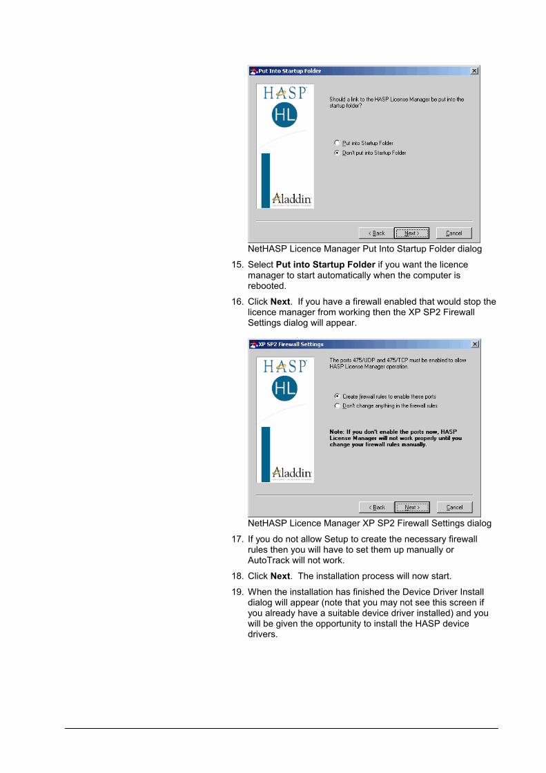
NetHASP Licence Manager Put Into Startup Folder dialog
15. Select Put into Startup Folder if you want the licence manager to start automatically when the computer is rebooted.
16. Click Next. If you have a firewall enabled that would stop the licence manager from working then the XP SP2 Firewall Settings dialog will appear.
NetHASP Licence Manager XP SP2 Firewall Settings dialog
17. If you do not allow Setup to create the necessary firewall rules then you will have to set them up manually or AutoTrack will not work.
18. Click Next. The installation process will now start.
19. When the installation has finished the Device Driver Install dialog will appear (note that you may not see this screen if you already have a suitable device driver installed) and you will be given the opportunity to install the HASP device drivers.

User Manual for AutoTrack Installing AutoTrack 9
NetHASP Licence Manager Driver Install dialog
20. The HASP device driver must be installed before the system will work so we recommend that you click Next to install them now. You should see a message that the hardware lock drivers have been successfully installed.
21. Click Next. The Start Licence Manager dialog will appear.
NetHASP Licence Manager Start Manager dialog
22. Make certain that the correct hardware lock is plugged in. The licence manager will not start unless the key is attached.
23. Select Yes to start the Licence Manager and then click Finish.
24. At this stage if you are using a USB dongle it should be glowing to indicate that it is working.

Installing the licence manager on a Novell Netware server
WarningThe Licence Manager will only work on servers which have IPX installed. You should use the Win32 Licence Manager for Netware IP installations.
1. Plug the hardware lock into the parallel port of your Novell Netware file server.
2. Copy the file HASPSERVE.NLM to the system directory of the file server.
3. To load the Licence Manager type
4. load haspserv
5. To remove the Licence Manager type
6. unload haspserv
7. To load the Licence Manager automatically, add the line
8. load haspserv
9. to the file AUTOEXEC.NCF in the sys:system directory.
Moving the NetHASP Licence Manager (Network version only)
If you wish to move the network hardware lock to a different server then proceed as follows:-
1. Uninstall or disable the NetHASP Licence Manager on the original server.
2. Install the NetHASP Licence Manager software on the new server as described above.
3. There is no need to enter a new authorisation keycode unless you have updated AutoTrack.
4. If you have set up AutoTrack to look for the licence manager at a specific IP address, you will need to update these now.

User Manual for AutoTrack Installing AutoTrack 11
Installing the NetHASP Licence Monitor software (Network version only)
The Licence Monitor can be installed on any computer on any computer on the network and allows users to see how many licences are currently available.
Installing the licence monitor on a Windows NT/2000/xp client computer
1. Insert the CD in the CD ROM drive of the chosen client computer. The CD will start automatically if autorun is enabled and you can proceed to step 4. If the CD does not start automatically then proceed as follows:-
2. Click the Start button and select Run. The Run dialog will appear.
Windows 2002 Run dialogue
3. Type d:setup (change the drive letter to suit your CD) and click on OK.
4. The CD browser will appear.
CD Browser
5. Click Install Network Utilities and then Install NetHASP Licence Monitor on a Win32 computer.
6. The Welcome dialog will appear.

Welcome dialog
7. Click Next. Accept the Aladdin licence agreement and click Next. The Choose Destination Location dialog will appear.
Choose Destination Location dialog
8. If you wish to change the default location then click Browseand select your preferred directory.
9. Click Next. The Backup Replaced Files dialog will appear.
Backup Replaced Files dialog

User Manual for AutoTrack Installing AutoTrack 13
10. We recommend that you opt to backup replaced files so that, in the event of a problem, you can reinstate your computer to the state it was revert to the prior to installing the software.
11. Click Next. The Start Installation dialog will appear.
Start Installation dialog
12. Click Next to begin the installation.
13. Once installed the Monitor can be run by selecting Start, Programs, Aladdin, Monitor, AKS Monitor.
Installing AutoTrackRun Windows as you normally would and follow the steps according to the media type.
NoteWindows NT users MUST be logged in with Administrator rights to install AutoTrack.
1. Insert the CD in the CD ROM drive. The CD will start automatically if autorun is enabled and you can proceed to step 4. If the CD does not start automatically then proceed as follows:-
2. Click the Start button and select Run. The Run dialog will appear.
Windows XP Run dialogue
3. Type d:setup (change the drive letter to suit your CD) and click on OK.
4. The CD browser will appear.
CD Browser
5. Click Install / Update / Remove AutoTrack.
WarningIf you have a newer version of AutoTrack installed, or the object enabler version these must be uninstalled manually before you can install standard AutoTrack.
6. On the Choose Setup Language dialog you can select your preferred installation language. Click Next.
7. If you are installing AutoTrack for the first time on a computer the Welcome to the Installshield Wizard for AutoTrack dialog

User Manual for AutoTrack Installing AutoTrack 15
will appear. Go to the next step.
If instead you see the Welcome to the AutoTrack Setup Maintenance dialog then you already have this version of AutoTrack installed on your computer. Refer to Modifying, repairing or removing AutoTrack.
If you are updating a previous version of AutoTrack then you will see the Earlier Version Found dialog.
Earlier Version Found dialog
Before you can install a new version of AutoTrack any previous version must be uninstalled. You have threeoptions:-
Select Cancel this installation if you don’t want the previous version removed just yet or if you want to remove the previous version yourself. Setup will close.
Select Uninstall but do not migrate settings if you want Setup to remove the previous version for you but you do not want to transfer your settings and/or custom vehicle libraries to the new version. The previous version will be uninstalled and when it is finished you will see the Welcome to the Installshield Wizard for AutoTrack dialog.
Select Uninstall and migrate settings if you want Setup to remove the previous version for you and transfer your settings and/or custom vehicle libraries to the new version. This is the recommended option. The settings will be backed-up up to a folder on the desktop, then the previous version will be uninstalled and the settings when be reinstated in the new version. When it is finished you will see the Welcome to the Installshield Wizard for AutoTrack dialog.

Welcome to the Installshield Wizard for AutoTrack dialog
8. Click Next to start the installation process. The Licence Agreement dialog will appear.
Licence Agreement dialog
9. Click Yes if you accept the terms of the licence agreement. The User Information dialog will appear.

User Manual for AutoTrack Installing AutoTrack 17
User Information dialog
10. Enter your details.
11. Click Next. The Setup Type dialog will appear.
Setup Type dialog
12. Select Express to install a stand alone version of AutoTrack on all available platforms. On AutoCAD platforms AutoTrack will be installed on the AutoTrack profile (which will be created if necessary). Update checking will be enabled. The XviD compression codec will be installed. Adobe Acrobat Reader will be installed if necessary. Go to step 42.
Select Compact if you want to install the program to all CAD systems found but want to specify the options. This option is ideal for creating silent script installs. Go to step 20.
Select Custom to choose which platforms you want to install or to exclude certain options.
13. Click Next. The Stand-alone AutoTrack dialog will appear.

Stand-alone AutoTrack dialog
14. Tick the box if you want the stand-alone Windows host installed.
15. Click Next. The first of ten (or eleven if you are installing on a 64-bit platform) CAD system selection dialogs will appear. This one is for the AutoCAD R14 based CAD systems.
CAD System dialog (AutoCAD R14)
16. Select the AutoCAD R14 based systems on which you wish to run AutoTrack by ticking the appropriate boxes. Note that all CAD systems that Setup has found on your system willhave the CAD program executable file in the edit box and will be selected by default. Setup can only fully install and configure AutoTrack for CAD systems that it can find.
17. If you wish to install support for a system that has no file listed then tick the option and click the appropriate Browse button. Now browse to the directory where Setup can find the required file. Any CAD system that you select that does not have a path listed will not be correctly installed.
18. Click Next. The AutoCAD 2000/2000i based system selection dialog will appear now followed by pages for AutoCAD 2002 to 2011, MicroStation systems and finally MicroStation PowerDraft systems.
User Manual for AutoTrack Installing AutoTrack 19
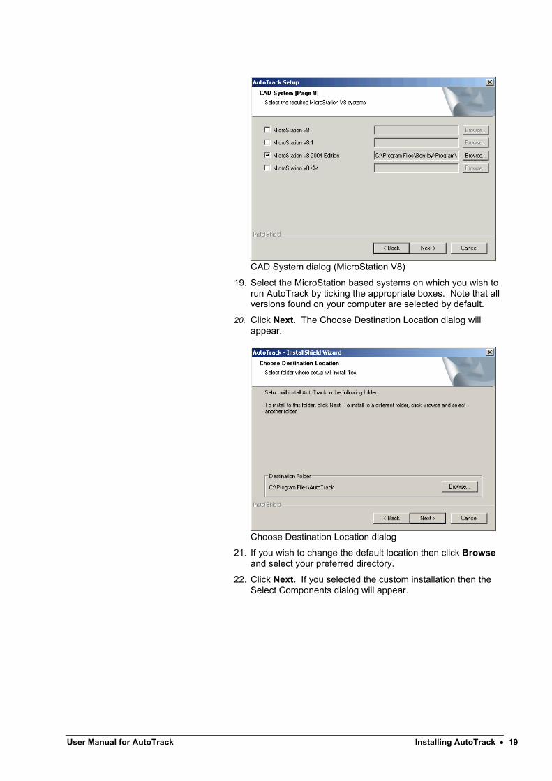
CAD System dialog (MicroStation V8)
19. Select the MicroStation based systems on which you wish to run AutoTrack by ticking the appropriate boxes. Note that all versions found on your computer are selected by default.
20. Click Next. The Choose Destination Location dialog will appear.
Choose Destination Location dialog
21. If you wish to change the default location then click Browseand select your preferred directory.
22. Click Next. If you selected the custom installation then the Select Components dialog will appear.

Select Components dialog
23. Select the components that you require by checking the boxes.
24. Click Next. The XviD Compression Codec dialog will appear.
XviD Video Compression Codec dialog
25. If you create an AVI file of an animation you will probably need to use a video compression codec to reduce the file size to a manageable level. Various video compression codecs are installed with Windows as standard but we have found the XviD video compression codec to be better than these in terms of both compression level and quality.
26. Click Next. The Adobe Acrobat Reader dialog will appear.

User Manual for AutoTrack Installing AutoTrack 21
Adobe Acrobat Reader dialog
27. More than likely you already have Adobe Acrobat Reader installed on your computer but if you don’t then you will not be able to read or print the AutoTrack documentation.
28. Click Next. The Network Licence Setup dialog will appear.
Network Licence Setup dialog
29. By default network versions of AutoTrack search for a network licence manager and maintain a search list automatically. We recommend that you use this default functionality. However, you may, if you wish, enter the IP addresses of up to four licence manager servers on this dialog. These addresses can also be maintained from AutoTrack.
30. Tick Only install support for network licences if you don’t want the local dongle drivers installed. These are only required if you are likely to use stand-alone (as opposed to network) dongles.
31. Click Next. The Internet Access dialog will appear.

Internet Access dialog
32. If you use a proxy server then you should enter the details here. You may suffix the Proxy server name with the port number if required, e.g. www.savoy.co.uk:8080.
33. Click Next. The Shared Data Directory dialog will appear.
Shared Data Directory dialog
34. Enter the full path of the directory you wish to use to share data within your company or department.
35. Click Next. The Update Advice dialog will appear.

User Manual for AutoTrack Installing AutoTrack 23
Update Advice dialog
36. By default end users have options to check for more recent versions of AutoTrack either automatically (at a specified time interval) or manually. If you wish to prevent users from checking for updates entirely then untick Allow update checking. If you wish to only allow them to perform manual checks then tick Allow manual check only. Finally, to allow them to check for updates but prevent them from downloading the file untick Allow downloads.
37. Click Next. The Configuration of CAD systems dialog will appear.
Configuration of CAD systems dialog
38. You may either allow Setup to configure your CAD systems now or leave it until the first time the software is run. We recommend that you allow Setup to configure your CAD system so that when subsequently uninstall the software all settings and registry changes are reinstated. If you tick Add an AutoTrack desktop shortcut Setup will add a shortcut icon for each platform that you have selected. Tick the options you require.
39. Click Next. If you have allowed Setup to configure your CAD systems then the AutoCAD Profiles dialog will appear.

AutoCAD Profiles dialog
40. On AutoCAD you can opt to install AutoTrack onto a copy of the current profile called AutoTrack or directly onto the current profile. By default it is installed on a copy of the current profile. Untick Install on profile AutoTrack if you want to add AutoTrack to the current profile. If a profile called AutoTrack already exists, AutoTrack will be added to it. If you opted to manually configure your system then AutoTrack will be installed onto the current AutoCAD profile each time it is run if necessary.
41. Click Next. The Select Program Folder dialog will appear.
Select Program Folder dialog
42. By default Setup will install AutoTrack to the AutoTrack folder. Select an existing alternative or enter a new folder name if you wish. Note you will not see this dialog if you are modifying an installation.
43. Click Next. The Confirm Edits dialog will appear.
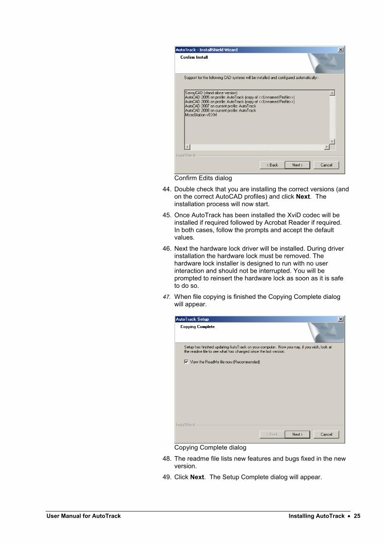
User Manual for AutoTrack Installing AutoTrack 25
Confirm Edits dialog
44. Double check that you are installing the correct versions (and on the correct AutoCAD profiles) and click Next. The installation process will now start.
45. Once AutoTrack has been installed the XviD codec will be installed if required followed by Acrobat Reader if required. In both cases, follow the prompts and accept the default values.
46. Next the hardware lock driver will be installed. During driver installation the hardware lock must be removed. The hardware lock installer is designed to run with no user interaction and should not be interrupted. You will be prompted to reinsert the hardware lock as soon as it is safe to do so.
47. When file copying is finished the Copying Complete dialog will appear.
Copying Complete dialog
48. The readme file lists new features and bugs fixed in the new version.
49. Click Next. The Setup Complete dialog will appear.

Setup Complete dialog
50. If it is necessary to restart your computer then you will be given the option to restart it now or later. Select your preference and click Finish.
51. If you chose to have Setup configure your CAD system for you then you should now be able to see AutoTrack on the top menu bar in AutoCAD or under the Applications menu on MicroStation.
52. If you chose not to allow Setup to configure your CAD system for you then refer to the section entitled Configuring AutoCAD manually or Configuring MicroStation, Bentley PowerDraft, Bentley PowerCivil or Bentley MX manually as appropriate.
Some final points to note
Windows NT based systems (NT4, 2000, XP, 2003, Vista, Windows 7, etc.)
Default location of application data files
By default the AutoTrack settings files, menus and other data files are stored in folders in the common application data directory. This is usually located as follows:-
On Windows XP or earlier it is C:\Documents and Settings\AllUsers\Application Data\AutoTrack,
On Windows Vista or later it is C:\Program Data\AutoTrack.
Storing application data files elsewhere
Where ever you choose to store your AutoTrack data files all users must be granted FULL access rights to this location.
If you wish to store the AutoTrack application data files in another location then create a file in the AutoTrack installation directory called SAVOY.INI containing the following lines:-
[SETTINGS]
ApplicationDataDir={Application Data Directory}
User Manual for AutoTrack Installing AutoTrack 27
Where the text in brackets (and the brackets themselves) should be replaced with the full path (or the path relative to the program installation directory) of the preferred data file location. For example:-
[SETTINGS]
ApplicationDataDir=D:\Example\AutoTrackAppData
You should then grant all AutoTrack users FULL access rights to this location.
Storing application data with the program
If you would rather your settings, menus and other application data files were stored with the program then we recommend that you do not specify the installation directory itself but create a subdirectory. Create a file in the AutoTrack installation directory called SAVOY.INI containing the following lines (we recommend AppData as a directory name but anything will do):-
[SETTINGS]
ApplicationDataDir=.\AppData
Then create AppData (or whatever you have called it) as a subdirectory of the program installation directory and grant all users FULL access rights. So, if you installed AutoTrack to the default location you need to create a directory called C:\Program Files\AutoTrack\AppData.
Access rights
AutoTrack must be installed by someone with Administrator rights. Depending upon your security policy, before you can run the software as an end user you may need to make changes to the user profiles. Login as a normal user and if AutoTrack is on the menu and runs you do not need to make the following changes. If AutoTrack is not on the menu and/or does not run then make the following changes as appropriate:-
Grant all AutoTrack users FULL access rights to the common application data directory. This is usually located as follows:-
On Windows XP or earlier, in the C:\Documents and Settings\AllUsers\Application Data\AutoTrack subdirectory
On Windows Vista or later, in the C:\Program Data\AutoTrackdirectory.
If you have specified an alternative application data directory in the SAVOY.INI file then grant all AutoTrack users FULL access rights to this directory.
Copy the AutoTrack menu from the Administrator's Start Programs menu to each AutoTrack user's menu.
If you are using Roaming Profiles consult your IT Department for advice.

Modifying, repairing or removing AutoTrackRun Windows as you normally would and follow the steps according to the media type.
NoteWindows NT users MUST be logged in with Administrator rights to install AutoTrack.
1. Insert the CD in the CD ROM drive. The CD will start automatically if autorun is enabled and you can proceed to step 5. If the CD does not start automatically then proceed as follows:-
2. Click the Start button and select Run. The Run dialog will appear.
Windows XP Run dialogue
3. Type d:setup (change the drive letter to suit your CD) and click on OK.
4. The CD browser will appear.
CD Browser
5. Click Install / Update / Remove AutoTrack.
NoteIf you have other applications running you may get a warning to close these applications so that shared files may be updated.

User Manual for AutoTrack Installing AutoTrack 29
6. If you see the Welcome to AutoTrack Setup dialog then you do not have a copy of AutoTrack installed on your computer. Refer to Installing AutoTrack.
If you see the Earlier Version Found dialog then you are installing a new version. Refer to Installing AutoTrack.
If you have installed new CAD systems since you installed AutoTrack, or if you did not originally install AutoTrack on all CAD systems on your computer, the Unsupported CAD Systems Found dialog will appear.
Unsupported CAD Systems Found Dialog
Depending upon your particular circumstances you may Add AutoTrack to newly installed CAD systems only or Add AutoTrack to all unsupported CAD systems. Setup will update your system and close when it has finished. You may also opt to Use the Modify option (see below).
If none of these apply, or if you opted to use the Modify option, the Welcome to the AutoTrack Setup Maintenance dialog will appear.
Welcome to the AutoTrack Setup Maintenance dialog

7. If you wish to add or remove support for a CAD system or to add or remove other program files (e.g. the on-line manual) select Modify. Refer to step 7 onwards in Installing AutoTrack.
If you have reason to believe that a file is missing or has become corrupted then select Repair. This will reinstall all the files installed by the previous setup to the same location.
If you wish to remove AutoTrack from your computer select Remove. You will be asked to confirm and then AutoTrack will be removed and Setup will close.

User Manual for AutoTrack Installing AutoTrack 31
Installing AutoTrack from the webAll AutoTrack versions are released on the Savoy web site before they are available on CD. In addition, minor updates are only available to existing users from the web site, CD’s only being issued on request.
All AutoTrack products are supplied in a single self-extracting executable with a file name of the form ATRxxx.EXE where xxx is the version number, e.g. ATR800.EXE. Note that the file is the full product and will install a full copy or update and existing copy.
You can configure AutoTrack to warn you when updates become available. If you download these updates they are placed in the My Documents\My AutoTrack Data\Updates folder. If you obtain updates by visiting the web site we recommend that you place these files in the same area.
To install the software
1. To install the software click the Start button on the Windows taskbar and select Run.
2. Browse to the file you have downloaded and click Open followed by Run.
3. AutoTrack Setup will run exactly as the CD version. For full details refer to either Installing AutoTrack or Modifying, repairing or removing AutoTrack depending upon whether you are installing or updating.
To extract the software
1. To extract the cabinet setup files to the target machine and not run setup type -extract_all:<path> after the filename in the Run dialog. Where <path> is the target folder. For example:-
atr800.exe -extract_all:c:\setupfiles
AutoCAD object enablerIn the AutoCAD version of AutoTrack the path entity is a custom object that is calculated and drawn by AutoTrack. Systems must therefore have AutoTrack installed in order to update and maintain these objects. Proxy graphics allow non-AutoTrack users to see the data (see Viewing AutoTrack paths in AutoCAD if you don’t have AutoTrack) but the functionality is very limited, e.g. you cannot snap to an AutoTrack path.
The object enabler is designed to give non-AutoTrack users limited functionality over AutoTrack data, allowing them, for example, to move reports or snap to a path to measure a distance. It also allows selection and playback of animations contained within a drawing.
The AutoTrack object enabler is free to download and is also available on the AutoTrack CD. It may be freely emailed to non-AutoTrack recipients of AutoTrack drawings. It cannot be installed with standard AutoTrack (there would be little point anyway).
This issue does not arise in the MicroStation or stand-alone versions that use different techniques.
ImportantUse of the object enabler does not in any way diminish our recommendation that you save proxy graphics with your drawing. Furthermore, you should note that if you make a change using the object enabler proxy graphics will only be resaved if you have the appropriate system variables set (see Viewing AutoTrack paths in AutoCAD if you don’t have AutoTrack).
To install the object enabler version from CD
1. First make sure that you do not have AutoTrack, either a demo or a full copy, installed.
2. Then insert the AutoTrack CD and when the CD menu appears, select Other Utilities. The installer will start.
3. Select Install Object Enabler version. Select Express to install the object enabler on all versions of AutoCAD found.
To install the software from the web
1. Download the object enabler version. It will have a filename of the form ATRxxxO.EXE, where xxx is the filename, e.g. ATR800O.EXE.
2. To install the software click the Start button on the Windows taskbar and select Run.
3. Browse to the file you have downloaded and click Open followed by Run. The installer will start.
4. Select Install Object Enabler version. Select Express to install the object enabler on all versions of AutoCAD found.

User Manual for AutoTrack Installing AutoTrack 33
Scripted 'silent' installationsAutoTrack Setup is fully MSI and ZENworks compatible allowing the full version (i.e. not the demo version) to be installed centrally and distributed on demand over a network with no user prompts.
The following instructions assume that you plan to install the software onto one or more client computers from a central source (file server).
Apart from obvious criteria such as adequate disk space, a successful silent installation requires that:-
the install source files are mapped to the same location for all client PC's, and
you either specify a Compact install or that all client computers have the selected CAD system(s) installed in the same location and run at least once.
Adobe Acrobat Reader and the XviD compression codec are third party applications and their installers require some user interaction. If you would rather users did not have to interact with the install process you should select Custom install and deselect these two options. Both items are installed if you perform an Express install.
Creating the install script
You must create the installation script on a client computer that is set up exactly as the other computers on which it will be installed silently.
1. Copy the ATRACK directory from the AutoTrack CD to a suitable location on your file server's hard disk.
2. Now go to one of the client computers. To create the silent install script you need to run Setup from the ATRACKdirectory on the server hard disk with a -r switch. The easiest way to do this is to create a shortcut on the desktop.
3. Browse to the ATRACK directory, right click on the file setup.exe and select Create Shortcut.
4. Move the shortcut to the desktop.
5. Right click on the new desktop shortcut, select Propertiesand add -r to the end of the Target field. The Target field should now read something like:-
f:\{source location}\atrack\setup.exe –r
6. Click OK to close the properties dialog.
7. Double click on this shortcut to start the AutoTrack installation and follow the prompts to install AutoTrack in the normal way.
8. Your selections and values will be stored in a file called setup.iss in the Windows directory. We recommend that you do not tick the options on the Finish dialog to view the readme file and to run the hardware lock wizard.
NoteIf you intend to deploy AutoTrack while users are not logged in then perform a Custom install and deselect the option Configure my CAD systems for me.

Running a silent install
1. Working from a client computer, move the file setup.iss from the Windows directory back to the ATRACK directory on the server's hard disk.
2. Now use windows explorer to browse to the file setup.exe in the ATRACK directory on the server.
3. Right click on the file and select Create Shortcut.
4. Move the shortcut to a suitable location accessible by all potential users (probably in a public area on the server).
5. Right click on the new desktop shortcut, select Properties and add the -s switch to the Target field. The Target field should now read something like:-
f:\{source location}\atrack\setup.exe –s
6. Click OK to close the properties dialog.
7. Double click on the desktop shortcut to start the silent install.
8. If you want to store the setup.iss file in another location use the additional switch –f1 to show Setup where to find it. For
example (no space between the f1 and the path):-
-f1{iss file path}\setup.iss
You may wish to create different iss files for installing, removing and maintaining AutoTrack each named appropriately (e.g. install.iss, remove.iss or maintain.iss) and referenced as described above. Note however that the silent setup operation will fail if you run it out of sequence, e.g. if you try to remove a copy of AutoTrack that has not been installed it will fail. The error log file (setup.log) is created in the same directory as the iss file. If the last entry in the file, under the heading [ResponseResult], is ResultCode = 0 then the operation was successful; otherwise, if failed.
Note that even a silent install will fail with an error if certain criteria are not met. These include the following:-
inadequate disk space,
previous version installed,
no CAD system selected,
CAD system still running,
the CAD system not having been run,
not running with administrator rights,
not having the required level of service pack,
both AutoCAD 2000 and AutoCAD 2002 installed (not allowed by Autodesk),
failure to perform an automatic edit,
failure to create the program folder, or
failure to migrate settings.

User Manual for AutoTrack Installing AutoTrack 35
Adding files to an installation
Setup can run a batch file or other executable after it has finished installing AutoTrack if you supply the name of the file you wish to execute as a command line switch in the following format:-
f:\{source location}\atrack\setup.exe –s –batch={batch filename}
For example:-
c:\atrack\setup.exe –s –batch=c:\atrack\setup.bat
Note, you can use the –batch switch with the –f1 switch.
Uninstalling AutoTrack
You can uninstall AutoTrack without going to Control Panel run Setup with a -uninst switch:-
f:\{source location}\atrack\setup.exe -uninst
However, this switch will still display a confirmation prompt.
To uninstall AutoTrack silently you will need to create an uninstall script. To do this go to a client computer that has AutoTrack installed and follow the steps in Creating the install script to create an uninstall script.
Updating AutoTrack
To perform a silent update of AutoTrack, we recommend that you run two scripts, one to uninstall the old version and a second to install the new version. This will require two .iss files referenced using the –f1 switch. For example you might run:-
c:\atrack\setup.exe –s –f1c:\atrack\remove.iss
Followed by:-
c:\atrack\setup.exe –s –f1c:\atrack\install.iss
These two commands could be run from a single batch file. However, if you do this you should use the –sms switch to ensure that the first instance of setup has finished before the second one starts. Hence your batch file would look something like this:-
c:\atrack\setup.exe –s –sms –f1c:\atrack\remove.issc:\atrack\setup.exe –s –sms –f1c:\atrack\install.iss

Configuring AutoCAD manuallyNoteRegistry changes made by either of the following 'manual' methods will not be removed when you uninstall the product and hence we recommend that you allow Setup to configure your AutoCAD system for you.
If you chose not to allow Setup to configure your copy of AutoCAD then proceed as follows…
Run AutoTrack from the Start Programs menu which will load AutoCAD and AutoTrack. This will configure your system and you should then be able to see AutoTrack on your AutoCAD menu bar. Henceforth, however you run AutoCAD, AutoTrack should appear on the menu bar.
Alternatively…
1. Run AutoCAD as you normally do.
2. Type APPLOAD at the command line.
3. If necessary change the Files of type box to include *.ARX.
4. Click the File button and browse to the AutoTrack directory (Normally C:\PROGRAM FILES\AUTOTRACK).
5. Highlight the program file appropriate to your CAD system as follows:-
For AutoCAD R14, Map R2, Map R3, Architectural Desktop, Land Development Desktop and other derivative products load the file ATRA140.ARX.For AutoCAD 2000, 2000i, Map 2000, Map 2000i, Architectural Desktop 2i, Land Development Desktop 2i and other derivative products load the file ATRA150.ARX.For AutoCAD 2002, Map 5, Map 6, Architectural Desktop 3, Architectural Desktop 3.3, Land Desktop 3 and other derivative products load the file ATRA1506.ARX.For AutoCAD 2004, Map 2004, Architectural Desktop 2004, Land Desktop 2004 and other derivative products load the file ATRA160.ARX.For AutoCAD 2005, Map 2005, Architectural Desktop 2005, Land Desktop 2005 and other derivative products load the file ATRA161.ARX.For AutoCAD 2006, Map 2006, Architectural Desktop 2006, Land Desktop 2006, Civil 3D 2006 and other derivative products load the file ATRA162.ARX.For AutoCAD 2007, Map 2007, Architectural Desktop 2007, Land Desktop 2007, Civil 3D 2007 and other derivative products load the file ATRA170.ARX.For AutoCAD 2008, Map 2008, Architecture 2008, Land Desktop 2008, Civil 3D 2008 and other derivative products load the file ATRA171.ARX.For AutoCAD 2009, Map 2009, Architecture 2009, Land Desktop 2009, Civil 3D 2009 and other derivative products load the file ATRA172.ARX.For 64-bit versions of AutoCAD 2009 based products, load the file ATRA17264.ARX.For AutoCAD 2010, Map 2010, Architecture 2010, Land

User Manual for AutoTrack Installing AutoTrack 37
Desktop 2010, Civil 3D 2010 and other derivative products load the file ATRA180.ARX.For 64-bit versions of AutoCAD 2010 based products, load the file ATRA18064.ARX.For AutoCAD 2011, Map 2011, Architecture 2011, Land Desktop 2011, Civil 3D 2011 and other derivative products load the file ATRA181.ARX.For 64-bit versions of AutoCAD 2011 based products, load the file ATRA18164.ARX.
6. Click Open.
7. Back in the Load/Unload Applications dialog click the Loadbutton and then close the Load/Unload Applications dialog.
8. If you use profiles then make the required profile current.
9. Type AUTOTRACK on the command line. AutoTrack will be loaded and your CAD system will be configured for use.
10. Repeat steps 7 and 8 for other profiles as required.

Configuring MicroStation, Bentley PowerDraft, Bentley PowerCivil or Bentley MX manually
Setup configures all Bentley CAD variants except MX (or MXROAD) to run AutoTrack when run from the AutoTrack for [Bentley product] desktop shortcut or menu item. AutoTrack can (and must for Bentley MX) also be loaded manually via the MDL Applications dialog. However, Setup no longer creates a new workspace and no longer adds AutoTrack to the list of Available Applications in other workspaces. If you want to do this then proceed as follows…
1. Run your Bentley CAD system as you normally would.
2. Select the User or Workspace you want to configure.
3. Create or open a file.
4. Select Configuration from the Workspace menu.
5. Select the category Primary Search Paths.
6. To make AutoTrack run in this workspace…Click on MDL Applications from the edit box at the top right and then click the Select button. Browse to the LOADERV8subdirectory of the AutoTrack installation directory and click Add to add it to the list. For example, if you installed AutoTrack to the default directory you should browse to C:\PROGRAM FILES\AUTOTRACK\LOADERV8\ (LOADER\on versions prior to V8) and click Add.
ImportantIf you enter the path manually using the Edit button, then note the backslash at the end of the path. This is critical.
7. Click Done to close the box. This will ensure that AutoTrack will run in MicroStation but it will not be listed in Available Applications.
8. To make AutoTrack available in this workspace…Click on Visible MDL Applications from the edit box at the top right and click the Select button. Browse to the LOADERV8 subdirectory of the AutoTrack installation directory (LOADER\ on versions prior to V8) and click Add to add it to the list. For example, if you installed AutoTrack to the default directory on MicroStation V8 you should browse to C:\PROGRAM FILES\AUTOTRACK\LOADERV8\ and click Add.
ImportantIf you enter the path manually using the Edit button, then note the backslash at the end of the path. This is critical.
9. Click Done to close the box. This will make AutoTrack visible to you while running MicroStation but will not load it automatically.
10. Click OK to close the Configuration dialog and allow the system to recognise the new search directories.
11. Now reopen the Configuration dialog by selecting Configuration from the Workspace menu.
12. Select the category Design Applications.

User Manual for AutoTrack Installing AutoTrack 39
13. To make AutoTrack autoload in this workspace…Look for ATRACK in the list of Available Applications. Highlight the entry and click the Add button to add it to the list of Applications to Load. This will make AutoTrack load automatically when you start MicroStation with this workspace.
14. Click OK to close the Configuration dialog.
15. Restart MicroStation with this user and AutoTrack should be on the Applications menu and the toolbar should be visible.
16. Repeat the above to configure other workspaces as required.

Resolving hardware lock problemsThe Hardware Lock Wizard starts automatically to attempt to resolvehardware lock problems detected whilst running AutoTrack. The wizard should be self-explanatory but in the unlikely event that it is unable to solve the problem please contact Savoy Computing Services for assistance.
The Hardware Lock Manager may be run independently of AutoTrack from the Start, Programs, AutoTrack program folder. This may be necessary if you are installing an update or if you just wish to check the status of your hardware locks.
Running the Licence Manager on the same computer as AutoTrack
AutoTrack can now safely be run on the same computer as the Licence Manager. However, you might need to add the "loopback" IP address to the list of IP addresses to search. This is because machines listening out for broadcast messages sometimes do not respond if the request is local.
To add the "loopback" address
1. Select Hardware Lock Manager from the Start, Programs, AutoTrack menu. The Hardware Lock Manager will appear.
2. Click the Configure Network Settings button. The Network Settings screen will appear.
Network Settings dialog
3. Click Configure Network Settings and add 127.0.0.1 to the list of searched IP addresses.
4. Click the Test Settings button to check that all is well. If not then refer to Identifying and resolving problems.

User Manual for AutoTrack Installing AutoTrack 41
Running the Licence Manager on a remote computer
AutoTrack may report one of two errors when it runs:-
17. No Free Licences Found.
18. No Licence Manager Found.
Message 1 means that there is not a problem, the licence manager has been found BUT there are no available licences, try again later.
Message 2 means that there is a problem. Refer to the next section, Identifying and resolving problems to fix it.
Identifying and resolving problems
1. Select Hardware Lock Manager from the Start, Programs, AutoTrack menu. The Hardware Lock Manager will appear.
2. Click the Configure Network Settings button. The Network Settings screen will appear.
Network Settings dialog
3. The Last Satus field should indicate the problem. Likely values include:-
15 - No Active NetHASP licence Manager was foundThis message means that the licence manager could not be found. To fix this, click the Add button and add the IP address of the licence manager computer. This should only be needed if the licence manager is running on a different subnet to the application, i.e. a WAN copy. Having added the IP address, click the Test Settings button to check that it now works.
If after adding the IP address, the computer is still unable to find the licence manager, then you may have a firewall preventing the system from working. To verify this we suggest that you temporarily disable the firewall and click on the Test Settingsbutton again.
155 - LM old version was foundThis message means that the licence manager has been found

BUT that it is an old version and needs upgrading. To fix this, download the latest version of the licence manager (v8.31.5.24 at the time of writing) from our web site (www.savoy.co.uk). Go to the Downloads page and select 3rd party software and links. Uninstall the current version from the licence manager machine and install the new version as a service. Note that upgrading the licence manager will NOT stop older versions of AutoTrack from running. Note also that during the upgrade process the licence manager machine may need to be re-booted.
129 - NetHASP key is not connected to the NetHASP Licence ManagerThis message means that the only licence manager found does not have a AutoTrack key attached. To fix this, make sure that the key is attached and then carry out the steps to add the IP address of the actual server outlined in the solution to error 15 about.
133 - Number of stations exceededThis message means that the licence manager has been found but all the licences are in use. Try again later, or use the Licence Monitor to see who is using the licences and get someone to logout.
Technical SupportYou may telephone Savoy Computing Services anytime during normal UK working hours on +44(0)1580 720 011. Alternatively you may fax us on +44(0)1580 720 022.
Normal working hours are 9am to 5.30pm GMT, Monday to Friday, except Bank and National Holidays.
If it's out of office hours then you might like to try our web site on which we post details of any known problems and how to work around them. The site can be accessed at www.savoy.co.uk and you can email us at [email protected]. Both of these are available from the AutoTrack drop down menu.
Finally, you can contact us by post at Savoy Computing Services Ltd., Clermont House, High Street, Cranbrook, Kent, TN17 3DN, England.

User Manual for AutoTrack Starting AutoTrack 43
Starting AutoTrack
AutoTrack can be run from within an AutoCAD or MicroStation session, from the taskbar Start, Programs menu or from a desktop icon. In future, when this manual refers to AutoTrack it is using the generic term and what each user will see depends on what version they are licenced to use.
Running stand-alone AutoTrack
Start button
1. Click on the Start button on the Taskbar and select AutoTrack for SavoyCAD from the Programs, AutoTrack menu or click on the desktop icon AutoTrack for SavoyCAD.
2. The first time the software is run, if AutoTrack cannot find a valid licence, the Welcome dialog will appear with options to run a full, rental or demo version. Select the required version.
3. If you are licenced only to use the Templates Standard version or have chosen to evaluate this product then you will see the first page of the Template Wizard.
In all other versions you will be placed in the SavoyCAD editor. AutoTrack should be visible on the top menu bar and the toolbar should also be visible.

Welcome dialog (1700)
The Welcome dialog appears whenever AutoTrack fails to find a valid licence or following a master reset.
Welcome dialog
1. By default, the language is detected automatically based upon your computer settings. However, if you would prefer to use a different language select it from the Preferred Language drop down list.
19. If you have just purchased AutoTrack and have a dongle then simply plug it in and click Full Version.
20. If you want to rent a copy of AutoTrack or receive a rental licence from a colleague, click Rental Version. The Rental Version dialog will appear.
21. If you simply want to try out the software click Demo Version. The Demonstration Version dialog
(1800)will appear.

User Manual for AutoTrack Starting AutoTrack 45
Demonstration Version dialog (1800)
This dialog only appears if you have opted to run a demonstration copy of AutoTrack. It allows you to select and change the product you wish to evaluate.
Demonstration Version dialog
1. Select the product(s) that you wish to evaluate.
22. To evaluate the selected product(s) click Continue.
23. If you want to rent a copy click Rent. This will display the Rental Version dialog
(1820), if this is available in your region,
and allow you to purchase time in weekly blocks.
24. If you have already purchased a copy and want to activate a supplied hardware lock then click Upgrade.
25. If you want to buy a copy then click Upgrade. This will either display the online purchasing dialog, if this is available in your region, or details of how to order.
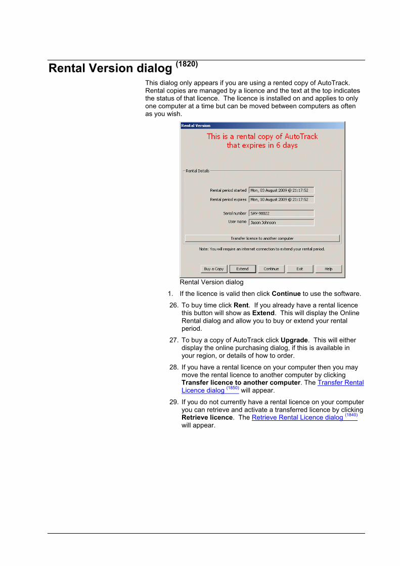
Rental Version dialog (1820)
This dialog only appears if you are using a rented copy of AutoTrack. Rental copies are managed by a licence and the text at the top indicates the status of that licence. The licence is installed on and applies to only one computer at a time but can be moved between computers as often as you wish.
Rental Version dialog
1. If the licence is valid then click Continue to use the software.
26. To buy time click Rent. If you already have a rental licence this button will show as Extend. This will display the Online Rental dialog and allow you to buy or extend your rental period.
27. To buy a copy of AutoTrack click Upgrade. This will either display the online purchasing dialog, if this is available in your region, or details of how to order.
28. If you have a rental licence on your computer then you may move the rental licence to another computer by clicking Transfer licence to another computer. The Transfer Rental Licence dialog
(1850)will appear.
29. If you do not currently have a rental licence on your computer you can retrieve and activate a transferred licence by clicking Retrieve licence. The Retrieve Rental Licence dialog
(1840)
will appear.
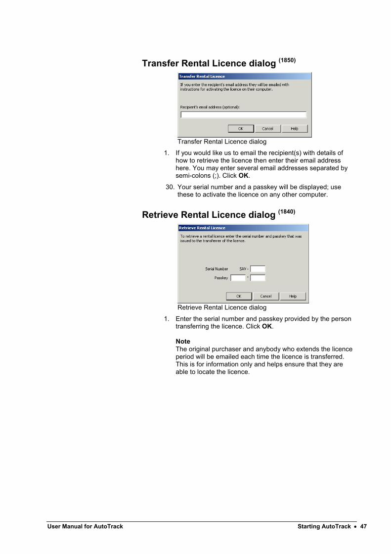
User Manual for AutoTrack Starting AutoTrack 47
Transfer Rental Licence dialog (1850)
Transfer Rental Licence dialog
1. If you would like us to email the recipient(s) with details of how to retrieve the licence then enter their email address here. You may enter several email addresses separated by semi-colons (;). Click OK.
30. Your serial number and a passkey will be displayed; use these to activate the licence on any other computer.
Retrieve Rental Licence dialog (1840)
Retrieve Rental Licence dialog
1. Enter the serial number and passkey provided by the person transferring the licence. Click OK.
NoteThe original purchaser and anybody who extends the licence period will be emailed each time the licence is transferred. This is for information only and helps ensure that they are able to locate the licence.

Running AutoTrack in AutoCADAutoTrack can either be run from within an AutoCAD session or from the Taskbar Start Programs menu.
To run AutoTrack from the Taskbar Start Programs Menu
Start button
AutoTrack menu
1. Click on the Start button on the Taskbar and select AutoTrack for AutoCAD 2011 (or your alternative CAD system) from the Programs, AutoTrack menu or click on the desktop icon AutoTrack for AutoCAD 2011.
2. The first time the software is run, if AutoTrack cannot find a valid licence, the Welcome dialog will appear with options to run a full, rental or demo version. Select the required version.
3. If you are running a demo copy then you will see the Demonstration Version dialog
(1800). Select which product
you wish to evaluate and click Continue. If necessary your menus will be reconfigured.
4. AutoTrack paths are only visible to non-AutoTrack users if proxy graphics have been saved with the drawing (for more information, refer to Viewing AutoTrack paths in AutoCAD if you don’t have AutoTrack). In order for these proxy graphics to be saved, several AutoCAD system variables need to be set correctly. If they are incorrect when you start AutoTrack they will be changed and you will be advised on the command line.
5. You will now be placed in the AutoCAD drawing editor. And the AutoTrack menu and toolbar should be visible.
AutoTrack toolbar (appearance varies)
6. If the toolbar is not visible select Show Toolbar from the AutoTrack drop down menu.
To run AutoTrack from within AutoCAD
1. Run AutoCAD as you normally would.
31. If your system has been set up correctly AutoTrack should be on the top menu bar. AutoTrack is not yet loaded but will be as soon as you select an AutoTrack command. If the toolbar is not visible then you can select Show Toolbar from the AutoTrack drop down menu to display it.
32. Click any AutoTrack button to load AutoTrack. If you are running a network version for the first time, you may get a Hardware Lock warning. Just confirm that you are running a network version and proceed. If AutoTrack fails to find the hardware lock, edit your Network Settings and enter the IP address of the Licence Server.
Note
User Manual for AutoTrack Starting AutoTrack 49
By default only the main AutoTrack toolbar is enabled with the other functions available as flyouts. If you prefer to work with the flyouts permanently displayed then click the relevant main toolbar buttons to display them and leave them open when you close AutoCAD. Alternatively on versions of AutoCAD prior to 2006 you may go to View, Toolbars and check the AutoTrack toolbars that you require.

To load and run AutoTrack for AutoCAD manually
1. Run AutoCAD as you normally would.
2. Select Load Application from the Tools menu in AutoCAD or type APPLOAD at the command line. The Load Application dialog will appear. The dialog shown is for AutoCAD 2002 but other platforms are similar.
Load Application dialog (AutoCAD 2002)
3. Browse to the AutoTrack application directory and select the ARX file appropriate to your CAD system as follows:-
AutoCAD R14 and derivatives use ATRA140.ARX
AutoCAD 2000/2000i and derivatives use ATRA150.ARX
AutoCAD 2002 and derivatives use ATRA1506.ARX
AutoCAD 2004 and derivatives use ATRA160.ARX
AutoCAD 2005 and derivatives use ATRA161.ATX
AutoCAD 2006 and derivatives use ATRA162.ATX
AutoCAD 2007 and derivatives use ATRA170.ATX
AutoCAD 2008 (32-bit) and derivatives use ATRA171.ATX
AutoCAD 2008 (64-bit) and derivatives use ATRA17164.ATX
AutoCAD 2009 (32-bit) and derivatives use ATRA172.ATX
AutoCAD 2009 (64-bit) and derivatives use ATRA17264.ATX
User Manual for AutoTrack Starting AutoTrack 51
AutoCAD 2010 (32-bit) and derivatives use ATRA180.ATX
AutoCAD 2010 (64-bit) and derivatives use ATRA18064.ATX
AutoCAD 2011 (32-bit) and derivatives use ATRA181.ATX
AutoCAD 2011 (64-bit) and derivatives use ATRA18164.ATX
4. Click the Load button. AutoTrack will load.
5. Now type AUTOTRACK on the command line.
6. If you have installed a demo copy then you will see the Demonstration Version dialog
(1800). Select which product
you wish to evaluate and click Continue. If necessary your menus will be reconfigured.
7. AutoTrack should now be visible on the top menu and the toolbar should also be visible. If the toolbar is not visible then you can select Show Toolbar from the AutoTrack drop down menu to display it.
8. Click any AutoTrack button to load AutoTrack. If you are running a network version for the first time, you may get a Hardware Lock warning. Just confirm that you are running a network version and proceed. If AutoTrack fails to find the hardware lock edit your Network Settings and enter the IP address of the Licence Server.
Note By default only the main AutoTrack toolbar is enabled with the other functions available as flyouts. If you prefer to work with the flyouts permanently displayed then click the relevant main toolbar buttons to display them and leave them open when you close AutoCAD. Alternatively on versions of AutoCAD prior to 2006 you may go to View, Toolbars and check the AutoTrack toolbars that you require.

Viewing AutoTrack paths in AutoCAD if you don’t have AutoTrack
In the AutoCAD version of AutoTrack the path entity is a custom object that is calculated and drawn by AutoTrack. Systems must therefore have AutoTrack installed in order to update and maintain these objects.
AutoCAD caters for drawings that contain custom objects without their authoring application being present using a system called proxy graphics. Proxy graphics are similar to an anonymous block containing an exploded version of the custom object. However, the proxy graphics will only be visible if certain system variables are set correctly on both the authoring and receiving systems.
Authoring system
In order for proxy graphics to be saved with the drawing the authoring system must have the system variable PROXYGRAPHICS set to 1 and INDEXCTRL set to 3. When you start AutoTrack these are set along with PROXYSHOW set
to 1 and DEMANDLOAD set to 3.
Receiving system
If the receiving system has AutoTrack installed and the startup system setting Load AutoTrack when opening drawing containing AutoTrack data is switched on, AutoTrack data will be visible just like any other entity. Likewise, if the AutoCAD object enabler is installed then any AutoTrack data will be visible. For more details of the object enabler refer to AutoCAD object enabler.
If the receiving system either does not have AutoTrack installed, or has AutoTrack installed but Load AutoTrack when opening drawing containing AutoTrack data is switched off, AutoCAD will report the missing application only if the system variable PROXYNOTICE is set to 1. This prompt may give the user options Show proxy graphics and/or Donot show proxy graphics. Note however that if proxy graphics have not been saved with the drawing (see above) then even opting to Show proxy graphics will not make them visible. Note also that if the default was Do not showproxy graphics and you select Show proxy graphics then you will need to issue a REGEN in order to see the objects.
If you decide not to show the proxy graphics at the start then setting PROXYSHOW to 1 will make them visible after the next REGEN if they are saved in the drawing.

User Manual for AutoTrack Starting AutoTrack 53
Running AutoTrack in MicroStationAutoTrack can either be run from within a MicroStation session or from the Taskbar Start Programs menu.
To run AutoTrack from the Taskbar Start Programs menu…
Start button
AutoTrack menu
1. Click on the Start button on the Taskbar and select AutoTrack for MicroStation V8i (or your alternative CAD system) from the Programs, AutoTrack menu or double-click on the desktop icon AutoTrack for MicroStation V8i.
2. Create and/or open a drawing.
3. The first time the software is run, if AutoTrack cannot find a valid licence, the Welcome dialog will appear with options to run a full, rental or demo version. Select the required version.
4. If you have installed a demo copy then you will see the Demonstration Version dialog
(1800). Select which product
you wish to evaluate and click Continue. If necessary your menus will be reconfigured.
5. You will be placed in the MicroStation drawing editor. AutoTrack should be on the Applications menu and the tool frame should also be visible docked on the left.
AutoTrack toolframe (Appearance varies)
6. Click any AutoTrack button to load AutoTrack. If you are running a network version for the first time, you may get a Hardware Lock warning. Just confirm that you are running a network version and proceed. If AutoTrack fails to find the hardware lock edit your Network Settings and enter the IP address of the Licence Server.

To run AutoTrack from within MicroStation…
1. Run MicroStation as you normally would.
2. Create and/or open a drawing.
3. If you have installed a demo copy then you will see the Demonstration Version dialog
(1800). Select which product
you wish to evaluate and click Continue. If necessary your menus will be reconfigured.
4. If your system has been set up correctly AutoTrack should be on the Applications menu. The AutoTrack tool frame may also be visible. AutoTrack is not yet loaded but will be as soon as you select an AutoTrack command.
5. Click any AutoTrack button to load AutoTrack. If you are running a network version for the first time, you may get a Hardware Lock warning. Just confirm that you are running a network version and proceed. If AutoTrack fails to find the hardware lock edit your Network Settings and enter the IP address of the Licence Server.
Note By default only the main AutoTrack tool frame is enabled with the other functions available as flyouts. If you prefer to work with the flyouts permanently displayed then go to Tools, Toolboxes and check the AutoTrack toolbars that you require.
User Manual for AutoTrack Starting AutoTrack 55
To load and run AutoTrack for MicroStation manually…
1. Run MicroStation as you normally would.
2. Select MDL Applications from the Utilities menu.
3. Look for ATRACK in the list of Available Applications.
4. If the application is listed then highlight it and click Load. Close the MDL Applications dialog.
5. If the application is not listed then click the Browse button and look in the LOADER subdirectory (LOADERV8 on MicroStation V8) of the AutoTrack installation directory for the file ATRACK.MA. Highlight the file and click OK followed by Load.
6. If you have installed a demo copy then you will see the Demonstration Version dialog
(1800). Select which product
you wish to evaluate and click Continue. If necessary your menus will be reconfigured.
7. AutoTrack should now be visible on the top menu and the toolbar should also be visible.
8. Click any AutoTrack button to load AutoTrack. If you are running a network version for the first time, you may get a Hardware Lock warning. Just confirm that you are running a network version and proceed. If AutoTrack fails to find the hardware lock edit your Network Settings and enter the IP address of the Licence Server.
Note By default only the main AutoTrack tool frame is enabled with the other functions available as flyouts. If you prefer to work with the flyouts permanently displayed then go to Tools, Toolboxes and check the AutoTrack toolbars that you require.

The New Features dialog (1975)
If you have an internet connection then you will see the New Features dialog when you run AutoTrack. If you do not see the dialog then it may be because it has been switched off. In this case select Show New Features from the AutoTrack, Help drop down menu.
New Features dialog
1. If you are installing AutoTrack for the first time the main window lists the new features add to this major release, e.g. if you are installing v8.9 it will list all new features from version 8.0.
2. If you have just updated from an earlier version the main window lists the new features available since the last version you used. Thus if you update from version 7.0 it will list all new features from that version.
3. If you don’t want to be reminded of new features again then tick Don’t remind me again. You can always see check the list again by selecting Show New Features from the AutoTrack, Help drop down menu.
4. Some of the items may include links to video clips. To view these simply click the Show me link.

User Manual for AutoTrack Starting AutoTrack 57
The Getting Started dialog (not AutoTrack Templates) (1900)
System Settings button
Tutor button
Video Tutorial button
Drawing Settings button
For those who use AutoTrack infrequently we have created the Getting Started dialog. By default this appears when you first run the program from the desktop icon.
Getting Started dialog
1. At the top of the screen is the Internet status. AutoTrack provides extra functionality via the internet and we strongly recommend that it is enabled. If the status indicates that there is a problem then click on the System Settings button to make changes.
2. Below that is the Assistance section. The AutoTrack Tutor is not new but now you can have it run at startup; tick Start the AutoTrack Tutor by default. There is a static tutorial provided with the product but for the most up to date information and advice we recommend that you access the online tutorial by ticking Use the Online Tutorial if available. If you tick Display in AutoTrack Window, the tutorial will appear in a dialog frame, otherwise it will run in your preferred browser. Click on the Tutor button or VideoTutorial button to start these features.
3. Below that is possibly the single most important settings, Drawing Scale. Enter your preferred scale or click the Drawing Settings button to configure other drawing settings.
4. The Driving Convention is set based upon your regional settings. You may change it if it is wrong.
5. The Preferred Editing Units control the units in which data is displayed. If you also wish to view or change the Reporting Units then click the Drawing Settings button.
6. When you become proficient with AutoTrack you may wish to disable the Getting Started dialog by ticking the box Do not show this dialog in future at startup. You can always display it again by selecting Getting Started from the AutoTrack drop down menu.

A few do's and don'tsWe have designed AutoTrack to support and interact appropriately with as many of the features of the host CAD system. However, there are a few recommended do’s and don’ts that you should bear in mind.
AutoCAD version
Do not save only exploded AutoTrack paths if you are likely to need to edit them in the future.
MicroStation version
Do not save only exploded AutoTrack paths if you are likely to need to edit them in the future.
Do not unlock or edit the AutoTrack cells using other than AutoTrack. Each AutoTrack path is held in one or more specially named locked cells (belonging to the same graphic group) to prevent it being manipulated such that the results are inconsistent with the vehicles capabilities. Unlocking or editing cells will have unpredictable results.
Do not try to edit AutoTrack data in reference drawings -AutoTrack can only access data in the master drawing.

User Manual for AutoTrack Introduction 59
Introduction
AutoTrack’s power and range of features has grown over the years and it is now no longer a single program but a suite of vehicle swept path prediction programs. It was originally developed to meet the need for a means of accurately predicting the space needed to manoeuvre large articulated vehicles. Nowadays, the program can model almost any conceivable vehicle type including vehicles with complex steering arrangements, aircraft and now, following the recent integration of AutoTram, light rail vehicles.
What AutoTrack can and can’t do
Capabilities
AutoTrack integrates completely with your CAD system adding functions that allow you to model vehicle behaviour. You simply select from a wide variety of predefined vehicles and 'drive' them through required manoeuvres on-screen. If the required vehicle is not already defined then facilities are provided to define the vehicle and add it into one of the existing libraries for future use.
NoteIf you are a new AutoTrack user, or have migrated from a previous version, we strongly recommend that you view the demonstration video supplied on the AutoTrack CD to gain an overview of the product. Then, for a hands-on introduction to using the program refer to the section entitled Worked Example.
Features
A number of features have been incorporated to simplify the user's task in "driving" a vehicle in this manner without the benefit of the more direct sensory feedback that would be experienced driving the vehicle for real.
It should be noted that the aim of the program is to provide accurate swept path predictions for different types of vehicles and not precise simulations of driving conditions for those vehicles. Thus, the controls have been designed with the emphasis on ease of use rather than realism.
Limitations
Like any engineering design program, AutoTrack has limitations. In fact, the list of factors that AutoTrack ignores is extensive and includes

dynamic effects, wind effects, acceleration and deceleration, sloping road surfaces and slippery road surfaces.
Whilst these factors are by no means irrelevant, if we asked you to supply a weather report, details of the condition of each tyre, a road friction coefficient and full details of the suspension you would probably give up and go back to using templates!
The fact is that AutoTrack is just like any other engineering program in which you design for idealised situations and apply safety factors to allow for real life variations.
This is exactly the way we recommend you use AutoTrack. Use the most onerous vehicles likely in a particular situation and then allow a margin for error on the results. The acceptable margin for error is something for you to assess - if you are lucky it may be the subject of local design guidelines.
Do not expect that just because a particular vehicle in the AutoTrack library can perform a given manoeuvre on your desktop you will be able to replicate it precisely in reality.
Do not assume that any of the AutoTrack defaults are recommendations and if you have a reliable source of data, use it.
It all boils down to USE YOUR ENGINEERING JUDGEMENT.
Migrating from WinTrackDue to restrictions imposed by Windows Vista support AutoTrack can no longer read WinTrack files directly. If you need to migrate WinTrack files for use with AutoTrack you should install version 7.60 or earlier, open the file and save it. The resulting file supports almost all WinTrack features. Features not supported include:-
Speed, hands-off and stationery steering reports (planned for a later release)
Full thickness tyre tread report (although tyre tread reports are read in as normal outer face wheel tracks if there is no outer face report defined)
Alternative direction symbol shapes (only the chevron shape)
Automatic grid spacing (however grid spacing may be specified)
Origin symbol (replaced by axes symbol at bottom left of screen)
Reading pre-v5 AutoTrack librariesDue to restrictions imposed by Windows Vista support AutoTrack can no longer read library files created using version of AutoTrack prior to version 5. If you need to convert an earlier format library file you should install version 7.60 or earlier, open the file and save it. The resulting file can be read in all versions of AutoTrack.
How to use AutoTrackAutoTrack is really very simple to use; in most cases you will simply specify your settings, select a vehicle from one of the many provided, position and orient it on your drawing and then drive it through your drawing on-screen. If you need a vehicle that is not listed then you can

User Manual for AutoTrack Introduction 61
create it, add it to your own vehicle library and use it just like those provided.
Each of these is described in detail in the following chapters.
Settings
How you use AutoTrack depends to a large extent upon what you want to do with it. The system is set up with default settings appropriate for a “typical” use. You will need to decide whether these are appropriate for your needs and change them if necessary.
The way a vehicle behaves is controlled partly by the vehicle parameters and partly by the environment in which it is driven. Vehicles once defined should normally be regarded as fixed. The environment settings however can and should be modified to suit your particular situation.
There are various drive modes available each of which can be used interchangeably. Each is appropriate for a particular use and you will need to decide which is best for your needs and indeed this may come down to a simple preference. All but one of the drive modes also have settings that control the way they work.
One of the most frequent causes of problems is that AutoTrack is working in one set of units (say, metres) while your CAD system is working in another (say, millimetres); so before you start work make sure that you set the AutoTrack scale to match your drawing (Refer to Drawing Settings: Scale).
AutoTrack calculates swept paths to a high degree of accuracy based upon the stated algorithms. However, you may wish to allow for the driver error or real world imperfections by modelling a safety or clearance envelope (Refer to Drawing Settings: Reports: Offset Envelope 1).
Modelling rigid vehicles
All drive modes are well suited to modelling rigid vehicles but AutoDrive is likely to give the quickest and best results.
Modelling articulated semi-trailer vehicles
Articulated lorries are best modelled using AutoDrive. Existing users may prefer Manual Drive which requires a degree of skill when reversing. Follow and Script may be appropriate if you are only modelling forwards manoeuvres. If you want to model reverse manoeuvres Script is unlikely to be of much use since it has no intelligence to deal with the over-articulation that will rapidly develop.
Modelling drawbar and multi-trailer vehicles
Multi-trailer vehicles that have more than one articulation point are inherently very unstable when reversing and for this reason they are rarely reversed. We do not encourage the use of AutoTrack to analyse multi-trailer vehicles performing reversing manoeuvres since it can give a false impression of the suitability of the design. Within AutoTrack, AutoDrive will give you good results.
Modelling aircraft
Taxiing aircraft are best modelled using either AutoDrive or Follow. Script may also be appropriate if you want to create templates of well-defined simple manoeuvres.
Follow will be appropriate if you want to model an aircraft following existing apron markings. If you want pilot’s eye tracking then you will need to change the Forwards Path Point to Pilot / Driver (Refer to Drawing Settings: Tracking Point). This must be done before you start driving. If your vehicle fails to negotiate a turn then you could try lengthening the segment length (Refer to System Settings: Follow Drive). The further the pilot is offset from the effective front axle the greater this value may need to be.
AutoDrive may be more appropriate if you are trying to determine the position of the apron markings. You will probably use the Forwards Arc option in AutoDrive which tries to drive with the minimum turn arcs and only use Forwards Bearing for long straight sections.
Modelling combination steered vehicles
Linkages have little effect on the most appropriate drive mode. However, rear steered vehicles do not have the benefit of Hands-Off in Manual Drive mode or Forwards Bearing in AutoDrive.
It is only possible to link entire axle groups so the best way to model a single linked axle in a multi-axle group is as a self-steered axle. Set the axle group type to Fixed and check the Self-Steered box on the axle that is linked. By default, with a self steered friction factor of 0.0, the effective axle position will be calculated on the basis of the remaining fixed axles and the wheels on the self-steered axle will turn about the centre of turn of these axles.
Modelling vehicles with pushing tractors
All vehicles must have a single tractor unit but it may be at the front, at the back or indeed, in the middle. In essence the behaviour of such a vehicle travelling forwards is equivalent to the reverse of the vehicle going backwards.
Modelling vehicles with steerable couplings
Some vehicles, notably certain quarrying trucks, have no steerable axles but instead are steered by changing the articulation angle of a coupling. These vehicles can be modelled using the active steerable coupling type.
Modelling Active Hitches
Warehouse vehicles sometimes make use of vehicles with active hitches. Active hitch refers to a rear drawbar axle which is linked to the front axle or coupling. Vehicles that use this type of axle can only be reversed using Manual Drive.
Development & planning scenarios
AutoTrack may be used not only to test scenarios but also to develop alignments from scratch. Used in this way you may find the need to limit the steering angle. This can be done in several ways but arguably the most useful in a development situation is by turn radius. For example, if
User Manual for AutoTrack Introduction 63
you were to adopt a standard curve radius for a residential development; this radius can then be set as the limiting inner wheel radius for all turns and all vehicles.
During the early planning stages of projects you may find that the good old turn template comes into its own. You could use the template wizard to generate templates for important vehicles such as refuse trucks and emergency vehicles and use them to form the basis of your road layouts. As you refine your design you can then use more sophisticated tools to test critical locations. You should bear in mind that turns generated using Script can be edited whereas those generated using the template wizard cannot.
Modelling the effects of super elevation and side friction
AutoTrack now allows you to restrict the turning radius according to super elevation and side friction. This, in conjunction with design speed, means that you can now more accurately predict higher speed paths through junctions or roundabouts. We do however urge caution before modelling high speed manoeuvres using AutoTrack; the dynamics of vehicle motion are too complex for a program of this type to fully model so the fact that AutoTrack can generate a theoretical path does not necessarily mean that it can be driven safely. USE YOUR ENGINEERING JUDGEMENT.
Modelling trams and light rail vehicles
You can only model fully rail guided vehicles such as trams using Guided Drive which is available in the light rail version. Generally speaking because the path of the tram is well defined there are fewer options. However because most new tram networks use new tram designs (albeit often heavily based upon existing trams) it is more likely that you will need to define your own vehicles.
Modelling conveyor systems
The Rail version can also be used to model certain types of conveyor systems such as are found in vehicle assembly plants.
Fastest line through roundabouts
Follow can be used to check the fastest line through roundabouts. Define the path through the roundabout as a AutoCAD spline, pline or MicroStation complex chain. Set the design speed to the highest permitted and use Follow to generate a non-editable path. AutoTrack will reduce the speed to the maximum possible. The current version does not take into account acceleration and deceleration but it does allow for dynamic effects.
Checking vertical clearances
The Vertical Clearance drive mode may be used to check ground clearance and / or impacts with overhead features such as bridges. Multiple axles are modelled assuming suspension movement. However, the results should be regarded as approximate since the effects of variations in suspension and loading can have a significant effect.

What’s new in version 8?Version 8 is the first 64 bit version of AutoTrack and is designed to run on 64 bit AutoCAD 2008, 2009 & 2010 and 64 bit Windows XP and Windows Vista. In addition we have managed to add a number of new features listed below. All files created with previous versions are fully upwardly compatible.
Mouse wheel controlled secondary steering (Wishlist item)
Control secondary steering at drive time using the mouse wheel.
Driver controlled secondary steering angle (Wishlist item)
Now you can control the secondary steering angle (not just the linkage) at drive time.
Rent AutoTrack online
You can now rent AutoTrack online in weekly periods.
Italian and Portugese versions
AutoTrack is now available in two new languages, Italian and Portuguese.
Improved grips with grip tips
All CAD hosts now have custom grip shapes for different operations. All grips have optional grip tips.
Ability to share data
A new single click option lets you share vehicle libraries or parking standards with others on your network.
Improved AutoLoad options
A new AutoLoad settings dialog lets you specify automatically loaded data by type, Savoy, Shared, Public, Personal and Other.
Directories settings dialog
A new Directories settings dialog lets you see where your data is being saved and specify the shared directory.
Internet settings dialog
A new Internet settings dialog lets you control how your system accesses the internet.
Significant speed improvements
Many features have been speeded up including library loading.
3D animation in Microstation
3D animation is now available in MicroStation.
Improved path editing in MicroStation
The path editing functionality in MS has been improved and now matches the grip editing capabilities available in AutoCAD.
Support for Bentley PowerCivil v8i
AutoTrack detects Bentley PowerCivil v8i and automatically installs support for it in Express mode.
Optional printing of construction lines (Wishlist request)
A new View settings option lets you prevent the plotting of construction lines. This feature does not apply to MicroStation which has its own construction line plotting support.

User Manual for AutoTrack Introduction 65
Updated vehicle libraries
The two Spancrete bridge beam carriers in the Specialist vehicle library have been updated to include manual secondary steering.
More 3D vehicles have been added to the 3D Presentation Vehicle library. These include a school bus, a panel van, a rigid truck, a Hummer, a single deck bus and a VW Beetle.
Support for Bentley PowerCivil XM
AutoTrack detects Bentley PowerCivil XM and automatically installs support for it in Express mode.
Online vehicle libraries
Access hundreds more vehicles stored in our online database from the Library Explorer.
Optional use of 3D blocks
You can now control when AutoTrack uses 3D blocks (if available). Options are Always, Never and When Recording.
Support for AutoCAD 2010 & all derivatives
AutoTrack detects AutoCAD 2010 and all verticals and automatically installs support for them in Express mode.
Improved use of program file and data areas
Settings and menus are now stored in the application data folder instead of the program files folder.
Resizable dialogs
The Updates, New Features & Drawing Explorer dialogs are now resizable.
Support for MicroStation V8i
AutoTrack detects Microstation V8i and automatically installs support for it in Express mode.
Support for Microstation PowerDraft (Wishlist item)
AutoTrack detects Microstation PowerDraft 7.1 to V8i and automatically installs support for it in Express mode.
Support for Bentley MX ROADS
AutoTrack detects Bentley MX ROADS XM and automatically installs support for it in Express mode.
Driver controlled variable ratio steering linkages (Wishlist prize winner)
The linkage ratio can be adjusted at each target point.
Support for multi-axle tandem bogies (Wishlist item)
You can now model units with identical or non-identical multi-axled tandem bogies. Each independent bogie has its own user-definable pivot offset.
Enhanced Turn on the Spot (Wishlist item)
It’s now easier to disable turn transitions for the current step only – one button press. New Transition settings to ignore all turn transitions and automatically set the optimum turning angle at the start of a path and/or at changes of direction.
Improved control over library auto-loading

You can now switch off library auto-loading without having to remove the files and directories from the list.
Enhanced jet exhaust report
Aircraft jet exhaust contours may be shown individually, each with their own colour and line type attributes. They may also be filled in the AutoCAD version.
Enhanced servicing point report
Servicing points can be shown individually.
New path stretch function
Paths can now be stretched so that, instead of each target point moving independently of the others, now all target points prior to or following the current point can be moved together.
German language version
AutoTrack is now available in German. The language can be changed from within the software.
Spanish language version
AutoTrack is now available in Spanish. The language can be changed from within the software.
Rounded corners on body shapes
You can now define a radius for the front, rear and corners of the rectangle shape and for the front and corners of the tractor body shape.
Improved library explorer vehicle copy/move (Wishlist item)
The vehicle copy/move action in the Library Explorer has been changed to match that used in Windows Explorer. Also the copy naming has been revised so that only the top level copied object has the words “copy of” added.
Library explorer search function
A single click library search function with history. Search the vehicle name, description, source and notes.
French design vehicle library
The design vehicles recommended by Centre d’Etude sur les Reseaux, les Transports, l’Urbanisme et les construction publiques (CERTU) have been added.
Vehicle library updates (Wishlist item)
The Alberta design vehicles in the Canadian Design Vehicle library have been updated with rounded corners.
The European vehicle library has more mobile cranes.
New Realistic vehicle library
We have added a new library of vehicles with detailed 2D (plan view) and 3D outlines for use in presentations.
New US vehicle library (Wishlist item)
We have added a library of real (as opposed to design) US vehicles. Amongst other vehicle types the library includes fire trucks and refuse trucks.
Improved hatching (Wishlist item)
In order to help clarify forwards and reverse envelopes you can now specify cross hatching for reverse sections of a manoeuvre.

User Manual for AutoTrack Introduction 67
Updated XviD codec
The latest XviD codec (v1.2.1) is bundled with this version.
64-bit compatible
AutoTrack 8 is fully compatible with the 64 bit versions of both Windows Vista and Windows XP.
AutoCAD 2008 & 2009 compatible
The new version is natively compatible with both the 32 and 64-bit versions of AutoCAD 2008 & 2009. AutoTrack detects AutoCAD 2008 & 2009 and derivative products and automatically installs support for them in Express mode.
Play animations backwards
You can now play animations backwards as well as forwards.
Ackerman stub axles
Ackerman stub axles can now be modelled.
Driving convention
There has been a minor change to the way in which we specify the driver position. We used to specify which side of the vehicle the steering wheel was on and now we specify which side of the road you drive on.
Option to fix driver position
An option has been added to allow or prevent the driver or pilot from being moved to the opposite side of a vehicle in accordance with the prevailing driving convention.
Driver shown on vehicle diagram
The driver or pilot is now shown on the vehicle diagram when the Show Datum button is depressed.
Pilot location added to library explorer columns
The driver or pilot location can now be viewed as a data column in the Library Explorer.
Default values highlighed in Library Explorer
Where a data column value displayed in the Library Explorer has not been explicitly defined it is shown in red.
Vehicle library updates
The refuse vehicles in the European Vehicle library have been updated and several fire vehicles have been added. There have also been minor changes to the Specialist Vehicle library and the Airport library.
AutoTrack menu icons in SavoyCAD
The AutoTrack menus in SavoyCAD now have icons.
Improved silent install
The silent install now makes no changes to the user area of the registry if you opt to manually configure the software. This allows the software to be deployed when the users are not logged in.
AutoDrive Bearing alignment picking
If you don’t know the angle you want to turn through when making a turn with AutoDrive Bearing you can pick a line on the drawing you want the vehicle to end up parallel or perpendicular to.
Cockpit tracking point

An alternative to the pilot’s eye tracking point, the cockpit tracking point is always located on the centreline of the aircraft.
Animation acceleration & deceleration (Wishlist prize winner)
An option has been added for vehicles to slow down and speed up realistically at stops or changes in speed. Acceleration and deceleration rates may be changed.
Interchangeable camera angles
The 3D animation camera position can be changed during an animation between previously stored camera positions and/or driver’s eye cameras on different paths.
Wing mirrors (Wishlist item)
You can now add default sized wing mirrors to a vehicle by ticking a single box. The dimensions and position can then be edited if required. The wing mirror location takes into account the driver position if one is specified.
Steering linkages by effective wheelbase
Specify linked steered axles by effective wheelbase as a function of articulation angle, steering angle and/or speed. Also allows you to specify different effective wheelbases for forwards and reverse manoeuvres.
Self steering direction
Specify self steered wheels for forward manoeuvres only, reverse manoeuvres only or in both directions.
Self steering tyre friction factor
Specify the friction contribution of self-steered axles. There is some evidence that, contrary to previous thinking, self steered axles do have an effect on the position of the cut in point. This feature allows you to specify their effect.
New features reminder
In response to a number of cases in which users were unsure of the new features added in an upgrade we have added a reminder dialog based upon user login names.
Tractor body shape
A new body shape has been added to better model the rather unique shape of articulated vehicle tractor units.
Driver / pilot
You can now add a driver at a default location by ticking a single box. The position can then be edited if required. The driver location takes account of the left/right driving convention.
Jet exhaust contour shape
A new shape has been added for jet exhaust contours. The shape allows exhaust temperature and velocity contours to be added by specifying just length and width of the shape.
Full width tyre tracks
An option has been added to show full width tyre tracks (instead of just the loci of the outer faces) for the outermost wheel of each axle. This is to help with modelling guided vehicles.
Steering graph added to report wizard

User Manual for AutoTrack Introduction 69
The steering and articulation graph report options have been added to the report wizard.
Improved Drawing Explorer
A Replace All button on the Drawing Explorer now allows you to copy properties to all paths at once.
User definable 3D animation colours
It is now possible to change the colours of individual vehicles in 3D animation.
Different default colours for forward and reverse (Wishlist item)
The forward and reverse reports now have different default colours making it easier to understand the manoeuvre.
GripTips in SavoyCAD version
GripTips, similar to ToolTips now appear as you hover over grips on AutoTrack entities in SavoyCAD. The tips list the coordinates of the grip, its type and the entity type.
Improved setup
A Compact setup type has been added to the existing Express and Custom. The new setup type allows you to auto-select the CAD systems but specify user defined options; very useful in silent remote installations.
Additions to aircraft library
The Bombardier DH Dash8 100 & 200 and nine Lektro aircraft tugs have been added to the aircraft library.
Animation single step back
You can now single step backwards as well as forwards through animations.
Updated Adobe Acrobat Reader
Adobe Acrobat Reader 8 is bundled with this version.
Support for AutoCAD 2011 & all derivatives
AutoTrack detects AutoCAD 2011 and all verticals and automatically installs support for them in Express mode.
AutoCAD Civil 3D 2011 specific features
Options added to project paths onto surfaces, generate vertical clearance paths on profile views directly and animate vehicles over surfaces in full 3D.
AutoCAD Ribbon (Wishlist item)
An AutoTrack Ribbon is included on all AutoCAD 2009, 2010 and 2011 based versions.
New Audit command
A new command that highlights possible inconsistencies in AutoTrack data and allows the designers to provide justification and explanatory comment.
AutoTrack Review
Some existing commands have been grouped with the new Audit command to create the AutoTrack Review feature set. Useful for validating AutoTrack work.
Danish design vehicle library

The design vehicles recommended by “Byernes trafikarealer, Haefte 1, Forudsaetninger for den geometriske udfomning”, published in 2000 by Vejdirektoratet have been added.
Finnish design vehicle library
The design vehicles recommended by “Tasoliittymat” published in 2001 by Tiehallinto have been added.
Czech design vehicle library
The design vehicles recommended by “Vlecne krivky pro overovani prujezdnosti prvku pozemnich komunikaci” published in 2004 by Centrum Dopravniho Vyzkumu have been added.
Support for custom actions in install process (Wishlist item)
A switch has been added which allows users to run a named batch or executable file after the main install has finished. This has been provided mainly for use when deploying AutoTrack silently.
Custom layer naming conventions (Wishlist item)
You can now specify a user-defined base layer name for Savoy layering conventions.
Improved memory handling (Wishlist item)
AutoTrack now uses between 50% and 75% less memory, leading to improved performance on all platforms and particularly on the memory hungry AutoCAD Civil 3D 2010.
Fly-by camera control
A new fly-by camera control lets you view animations from any angle in real time.
Wing mirror views
Drivers eye animations optionally show the wing mirror view of the inside of the turn when reversing.
Drivers eye follows road
Drivers eye animations optionally have the driver focusing either on a point a specified distance in front of the vehicle or straight ahead.
Text on side of vehicle
Add your sponsors name to your animations.
Animation in AutoCAD improved
Animation in all AutoCAD versions has been considerably improved and is now much smoother.
Additional render modes (Wishlist item)
Three new render modes have been added. These are Realistic, Conceptual and Basic.
PDF vehicle data filename (Wishlist item)
The default filename for AutoTrack vehicle data printed to PDF file where the data relates to a single vehicle now includes the vehicle name.
Improved aircraft servicing points & vehicles
The aircraft version has a new tab on the unit details listing servicing points and servicing vehicles. This data is not available for all aircraft.
Aircraft safety zone report

User Manual for AutoTrack Introduction 71
The aircraft version has a safety zone report with customisable wing, fuselage and tail offsets.
Aircraft doors
The aircraft version has a new tab on the unit details listing passenger, cargo and service doors. This data is not available for all aircraft.
Helicopters
The aircraft library now contains a range of helicopters.
Manual layoutIf the theory and algorithms used in AutoTrack are new to you then you may wish to read the section entitled Theory before using the program. Thereafter, the remaining sections cover day-to-day use of the program. We do however strongly recommend that you read the section entitled Worked Example which will give you a fast introduction to the program and get you productive as quickly as possible.
The troubleshooting section deals with some of the more common problems.
Notation conventions
Throughout this manual key depressions are shown enclosed by angle brackets thus enter <F> means type the letter F and <OR> means type the letters O and R.
Menu options or commands are printed in a bold font.
Messages displayed by AutoTrack are printed in italics.
Text that you should type and filenames are shown in a courier font.
All screen images and functionality descriptions are for AutoTrack running on Windows XP. The screen image may vary slightly on other platforms. If functionality is different for other platforms the variations are noted.
Mouse conventions
Windows allows mouse button functionality to be reversed for left handed users. AutoTrack features a similar option. Rather than repeatedly catering for all possible configurations we have adopted the convention of using the default functionality. Thus if you have configured your mouse for left handed use then for left mouse button read right mouse button and vice versa.
Default values
Throughout the program default values are displayed in red and have an asterisk alongside them. Enter any non-zero value to overwrite the default. Enter zero to reset them to the default.
Getting helpIf the user manual is not available try one of the alternatives.

Context sensitive on-line help
The extensive context sensitive on-line help mirrors the manual, but has the powerful windows search facilities. To get help click the Help button on any dialog or press F1.
Help is also available from the drop down menus:-
Select Help, AutoTrack Help to get a structured breakdown of the help text.
Select Help, About AutoTrack to check the program module versions.
On-line assistance
If you find what you think is a bug and wish to email support for assistance select Email Savoy Computing for assistance from the Help menu.
You can check for updates by selecting Check website for AutoTrack updates from the Help menu.
Help tutor
Tutor button
The AutoTrack Tutor is an AutoTrack help window that is displayed permanently in a convenient location on your desktop. The text updates as you move through the program. You can enable the help tutor at any time by clicking the Tutor button on the AutoTrack toolbar. We recommend that you set it to remain in the foreground at all times.
Video tutorial
Video Tutorial button
The AutoTrack video tutorial is a multi-media presentation designed to get you started with AutoTrack quickly. Video clips show you how to use AutoTrack to perform various tasks. It may be viewed as a continuous presentation or you may use the navigation buttons to view selected clips. We recommend that you use the online tutorial if you can.
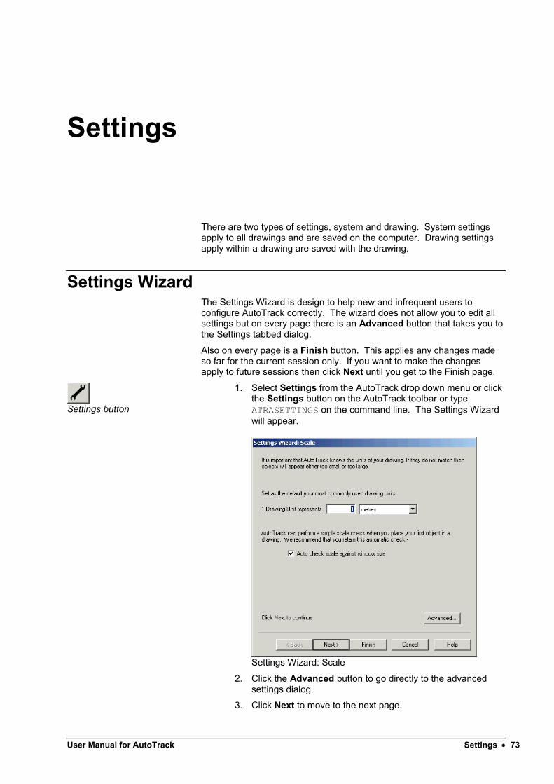
User Manual for AutoTrack Settings 73
Settings
There are two types of settings, system and drawing. System settings apply to all drawings and are saved on the computer. Drawing settings apply within a drawing are saved with the drawing.
Settings WizardThe Settings Wizard is design to help new and infrequent users to configure AutoTrack correctly. The wizard does not allow you to edit all settings but on every page there is an Advanced button that takes you to the Settings tabbed dialog.
Also on every page is a Finish button. This applies any changes made so far for the current session only. If you want to make the changes apply to future sessions then click Next until you get to the Finish page.
Settings button
1. Select Settings from the AutoTrack drop down menu or click the Settings button on the AutoTrack toolbar or type ATRASETTINGS on the command line. The Settings Wizard will appear.
Settings Wizard: Scale
2. Click the Advanced button to go directly to the advanced settings dialog.
3. Click Next to move to the next page.

Settings Wizard: Scale (2400)
Settings Wizard: Scale
1. Set the drawing units.
2. We recommend that you tick Auto check scale against window size since this will warn you if your scale appears to be wrong.
3. Click Next to move to the next page.

User Manual for AutoTrack Settings 75
Settings Wizard: Editing Units (2410)
Settings Wizard: Editing Units
1. The editing units determine the units used to display data.
2. Use the drop down list boxes to set your preferred units for distance, speed and angles.
3. Click Next to move to the next page.
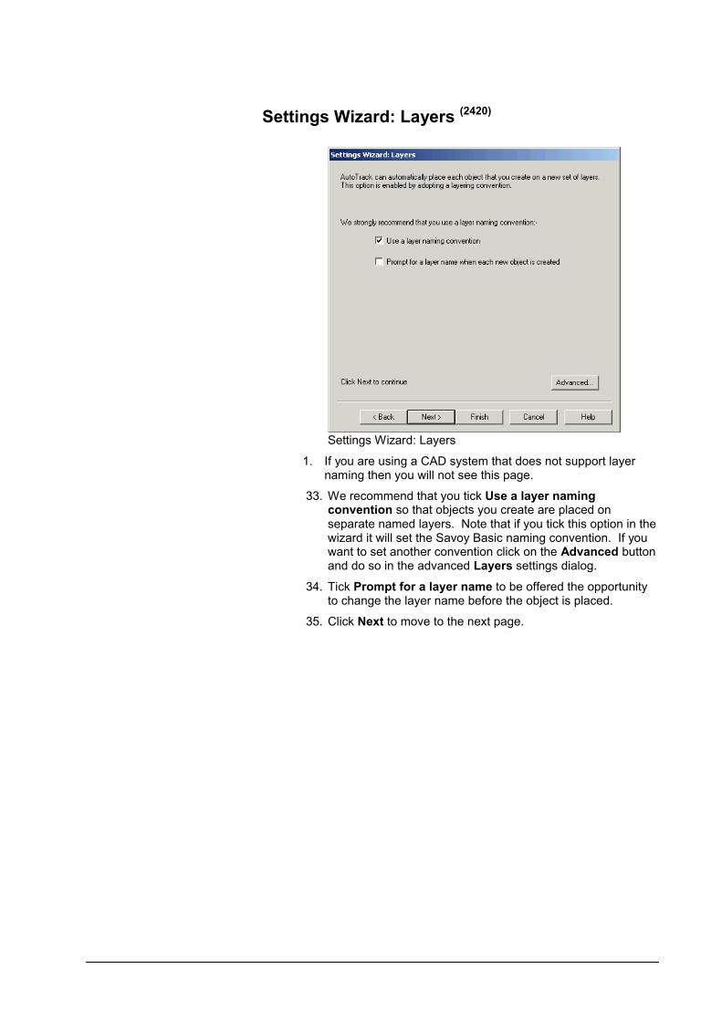
Settings Wizard: Layers (2420)
Settings Wizard: Layers
1. If you are using a CAD system that does not support layer naming then you will not see this page.
33. We recommend that you tick Use a layer naming convention so that objects you create are placed on separate named layers. Note that if you tick this option in the wizard it will set the Savoy Basic naming convention. If you want to set another convention click on the Advanced button and do so in the advanced Layers settings dialog.
34. Tick Prompt for a layer name to be offered the opportunity to change the layer name before the object is placed.
35. Click Next to move to the next page.

User Manual for AutoTrack Settings 77
Settings Wizard: Turn Transitions (2440)
Settings Wizard: Turn Transitions
1. In reality it is not good driving practice to turn the steered wheels whilst the vehicle is stationery. We therefore recommend that you limit turn rates. To do this tick Limit forward turn rate or Limit reverse turn rate.
2. The most realistic way to limit turn rates is by lock to lock time. So if, for example, you tick Limit forward turn rate then the steering rate criteria is automatically set to Limit by lock to lock time. Likewise for Limit reverse turn rate.
3. You can remove steering rate limits by unticking Limit forward turn rate but if you want to adopt different limiting criteria click the Advanced button and do so in the advanced Transitions settings dialog.
4. Click Next to move to the next page.

Settings Wizard: Design Speed (2430)
Settings Wizard: Design Speed
1. The design speed can affect the turning capabilities of the vehicle if you have limited turning by lock to lock time.
2. Even if you have not selected speed related turn transitions the design speed will affect the animation speed.
3. Click Next to move to the next page.

User Manual for AutoTrack Settings 79
Settings Wizard: Steering Limits (2450)
Settings Wizard: Steering Limits
1. You can limit the steering in three ways mutually inclusive ways, i.e. you can switch them all on and AutoTrack will determine the most onerous case and use that.
2. Tick Limit steering to percentage and edit the value to prevent the steering from exceeded the stated percentage of its maximum lock capability.
NoteThis is the only way to limit the steering lock in a vehicle independent way.
3. Tick Limit steering to angle and edit the value to prevent the steering lock exceeding a specified angle (in either direction).
4. Tick Limit steering to radius and edit the value to prevent the steering lock exceeding a value that would cause the vehicle to turn tighter than the specified radius. Note that you can specify where the radius is measured, Inner wheel, Inner body, etc.
5. Click the Advanced button to set these values in the Model Settings dialog (see Drawing Settings: Model (not Rail)).
1. Click Next to move to the next page.
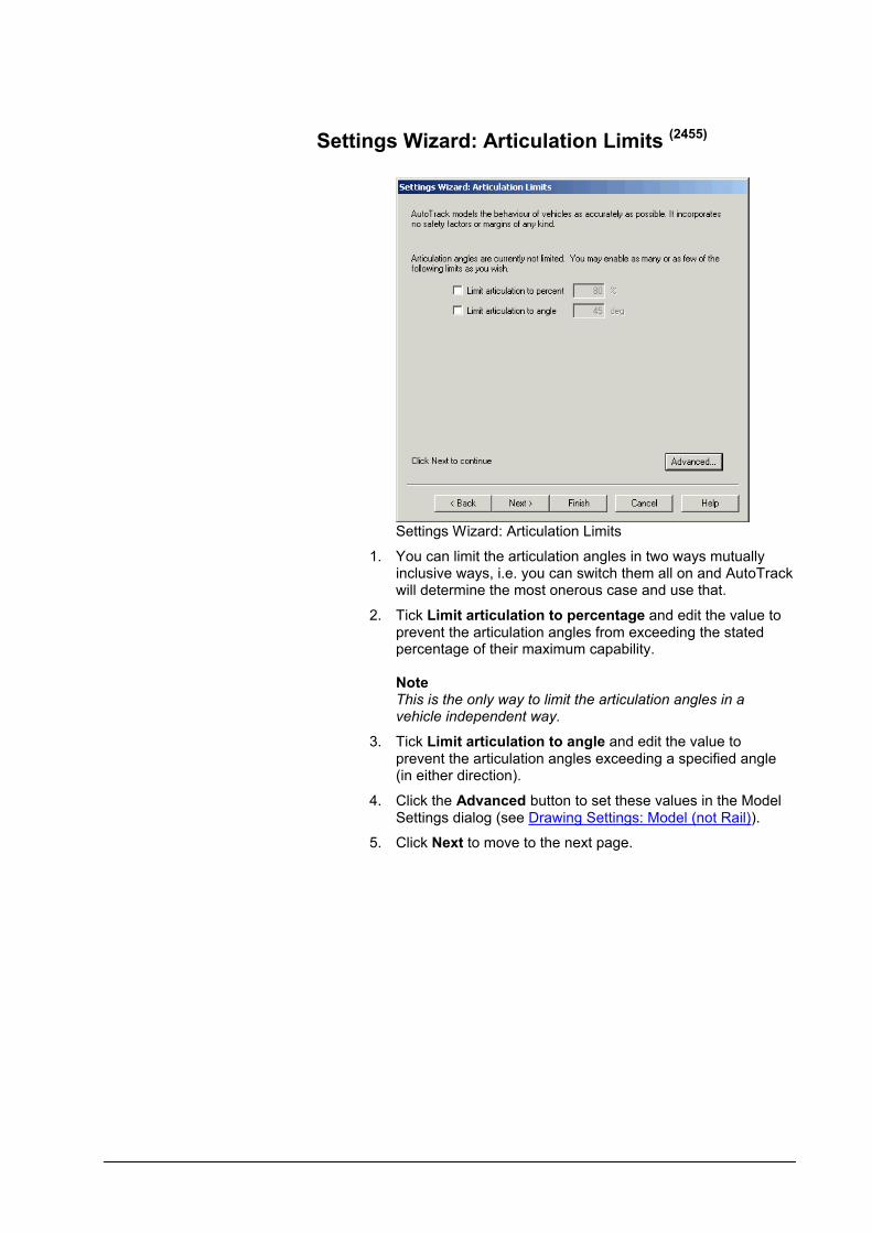
Settings Wizard: Articulation Limits (2455)
Settings Wizard: Articulation Limits
1. You can limit the articulation angles in two ways mutually inclusive ways, i.e. you can switch them all on and AutoTrack will determine the most onerous case and use that.
2. Tick Limit articulation to percentage and edit the value to prevent the articulation angles from exceeding the stated percentage of their maximum capability.
NoteThis is the only way to limit the articulation angles in a vehicle independent way.
3. Tick Limit articulation to angle and edit the value to prevent the articulation angles exceeding a specified angle (in either direction).
4. Click the Advanced button to set these values in the Model Settings dialog (see Drawing Settings: Model (not Rail)).
5. Click Next to move to the next page.

User Manual for AutoTrack Settings 81
Settings Wizard: Dynamics (2460)
Settings Wizard: Dynamics
1. If you are modelling turns at faster than about 15kph dynamic effects become significant. When you make a turn at higher speed the limiting criteria may be driver comfort rather than vehicle geometry. We recommend that you tick Limit turning for dynamic effects when modelling higher speed turns.
2. The wizard only allows you to select from published criiteria, if you want to define your own criteria click the Advancedbutton and do so on the advanced Dynamics settings dialog.
3. Click Next to move to the next page.

Settings Wizard: Updates (2470)
Settings Wizard: Updates
1. If you have an internet connection AutoTrack can check for updates for you. Tick Check for updates to enable this feature and enter the frequency of checking. If you enter zero AutoTrack will check for updates every time it is run.
2. Click Next to move to the next page.

User Manual for AutoTrack Settings 83
Settings Wizard: Finish (2480)
Settings Wizard: Finish
1. If you don’t want to have to keep changing these settings every time you run AutoTrack then select Use these settings for this and all future sessions. Otherwise, select Use these settings for all new paths in this session only.
2. Click Finish to confirm your selection.

Report WizardThe Report Wizard is design to help you to setup your AutoTrack reports correctly. It can actually be used to create or edit either your default reports or reports associated with existing paths.
The wizard does not allow you to edit all settings but on every page there is an Advanced button that takes you to the Reports tabbed dialog.
Also on every page is a Finish button. This applies any changes made so far for the current session only. If you want to make the changes apply to future sessions you should click Next until you get to the Finish page.
Report Wizard button
1. Select Report Wizard from the AutoTrack drop down menu or click the Report Wizard button on the AutoTrack toolbaror type ATRAREPORTWIZARD on the command line. The Report Wizard will appear.
Report Wizard: Start
2. Click the Advanced button to go directly to the Drawing Settings: Reports dialog.
3. Click Next to move to the next page.

User Manual for AutoTrack Settings 85
Report Wizard: Start (3700)
Report Wizard: Start
1. The wizard only allows you to edit one report at a time. If you have more than one report defined they will be listed in a drop down list box and you must select which report you want to change.
2. The current visibility is displayed under the drop down list.
If the report is not currently visible:-Tick Report visible to make the report visible. If you want to hide all the other reports then tick Exclusively. This is the quickest way to switch between reports.
If the report is currently visible:-Untick Report visible to hide the report. This will not affect any other reports listed so you may then want to select another report to show.
3. Click the New button to add a report to the list. The new report will be selected and you should then use the wizard to set it up as you require.
4. When you have finished your manoeuvre you may want to untick Construction lines to reduce the clutter. If you want to change which construction lines are displayed or their colour, either continue through the wizard to the relevant page or click the Advanced button and use the Drawing Settings: Reports dialog.
5. If you want to enable other combinations of reports click the Advanced button.
6. Click Next to move to the next page.

Report Wizard: Graphical sub-reports (3710)
Report Wizard: Body Outlines (other graphical sub-reports are similar)
1. Select where you want this element using the tick boxes.
2. All pages except Body Outlines have a further option, At all body positions, to display them at all positions at which a body outline is drawn.
3. The attributes buttons on the right show the line colour and style. Click on the button to change these in the Report Attributes dialog
(3820).
4. If the page has an envelope option and you want to set the hatch spacing or angle or if you want to define an offset envelope click the Advanced button.
5. Click Next to move to the next page.

User Manual for AutoTrack Settings 87
Report Wizard: Path Annotation (3790)
Report Wizard: Path Annotation
1. Select where you want this element using the tick boxes.
2. The vehicle name is displayed at all discrete locations selected and the the path number is displayed at a regular spacing if selected.
3. The attributes buttons on the right show the line colour and style. Click on the button to change these in the Report Attributes dialog
(3820).
4. If you want to set display something other than the vehicle name or the path number click the Advanced button.
5. Click Next to move to the next page.
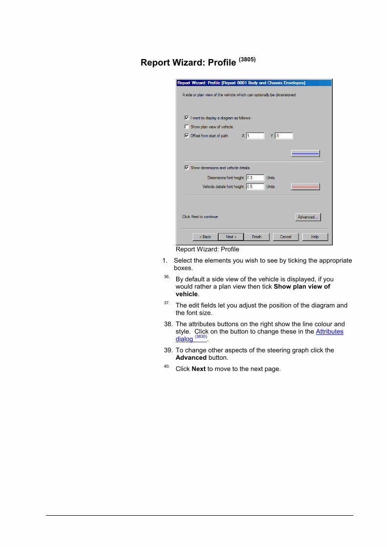
Report Wizard: Profile (3805)
Report Wizard: Profile
1. Select the elements you wish to see by ticking the appropriate boxes.
36.By default a side view of the vehicle is displayed, if you would rather a plan view then tick Show plan view of vehicle.
37.The edit fields let you adjust the position of the diagram and the font size.
38. The attributes buttons on the right show the line colour and style. Click on the button to change these in the Attributes dialog
(3830).
39. To change other aspects of the steering graph click the Advanced button.
40.Click Next to move to the next page.

User Manual for AutoTrack Settings 89
Report Wizard: Steering & Articulation Graph (3795)
Report Wizard: Steering & Articulation Graph
1. Select the elements you wish to see by ticking the appropriate boxes.
2. The attributes buttons on the right show the line colour and style. Click on the button to change these in the Attributes dialog
(3830).
3. To change other aspects of the steering graph click the Advanced button.
4. Click Next to move to the next page.
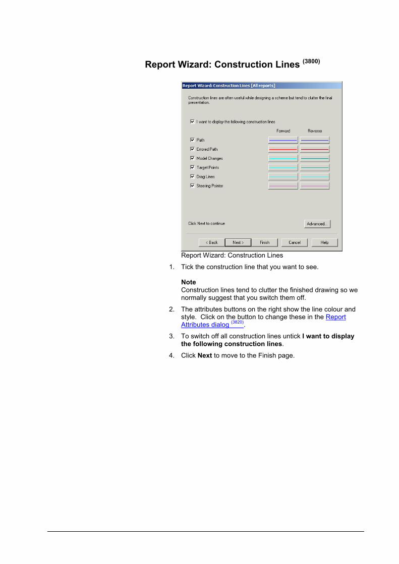
Report Wizard: Construction Lines (3800)
Report Wizard: Construction Lines
1. Tick the construction line that you want to see.
NoteConstruction lines tend to clutter the finished drawing so we normally suggest that you switch them off.
2. The attributes buttons on the right show the line colour and style. Click on the button to change these in the Report Attributes dialog
(3820).
3. To switch off all construction lines untick I want to display the following construction lines.
4. Click Next to move to the Finish page.

User Manual for AutoTrack Settings 91
Report Attributes dialog (3820)
Report Attributes dialog
1. Select the Colour from the drop down list of 254 pens. To set a custom colour select {custom} and click on the colour swatch.
2. Select the Line type from the drop down list. The line types listed are those currently available in your CAD system. If you wish to add a line type you should cancel this dialog and create the line type in your host CAD system.
3. Select the Line weight from the drop down list.
NoteLine weights are real world dimensions so if you select a line weight of 2mm the object will be drawn with 2mm thick lines.
Attributes dialog (3830)
Attributes dialog
1. Select the Colour from the drop down list of 254 pens. To set a custom colour select {custom} and click on the colour swatch.
2. Select the Line type from the drop down list. The line types listed are those currently available in your CAD system. If you wish to add a line type you should cancel this dialog and create the line type in your host CAD system.
3. Select the Line weight from the drop down list.
NoteLine weights are real world dimensions so if you select a line weight of 2mm the object will be drawn with 2mm thick lines.

Report Wizard: Finish (3810)
Report Wizard: Finish
1. If you don’t want to have to keep changing these settings every time you run AutoTrack then select Use these settings for this and all future sessions. Otherwise, select Use these settings for all new paths in this session only.
2. If you have a path selected then a third option will be displayed, Use these settings for the selected path only. This allows you to quickly change the report properties for the selected path.
3. Click Finish to confirm your selection.

User Manual for AutoTrack Settings 93
System SettingsThe AutoTrack System Settings control the default behaviour of AutoTrack in all drawings on the CAD system. The settings are displayed all at once on a single tabbed dialog.
System Settings button
1. Select System Settings from the AutoTrack drop down menu or click the System Settings button on the AutoTrack toolbar or type ATRASYSTEMSETTINGS at the command line. The System Settings dialog will appear.
System Settings dialog
2. Click the appropriate tab to edit or view the settings.
3. Edit the data as required and click OK to confirm when you are satisfied. Click Cancel to abort all changes and close the System Settings dialog.
4. Click Make Default to save the displayed settings as defaults for the next session. Click Reset to restore your last saved default settings following changes.

System Settings: Start Up (2000)
1. Click on the Start-Up tab.
System Settings dialog: Start Up tab
2. Tick Show disclaimer to display the disclaimer at the start of each session.
3. By default all settings are stored in the Settings subdirectory of the application data directory. This means that changes made by one user affect all others. To instead store the program settings in each users My Documents data folder, tick Store settings in “My Documents” folder.
NoteYour computer may still be configured so that the My Documents folder is a common area.
4. Should you wish to apply common settings for all users but wish to disallow write access to the application tree you can edit the file SAVOY.INI in the AutoTrack installation directory. Open the file in a text editor and find the line [SETTINGS]. If this line does not exist add it at the bottom of the file. Then add or edit the line ApplicationDataDir={Application Data Directory} to point to the required directory (see Some final points to note for more details).
5. Tick Save library changes on leaving library explorer if you want AutoTrack to automatically update the library files with any changes when you leave the library explorer. If you do not tick this box you will be asked if you want to update the library file every time you close the library explorer.
6. Tick Force menu to be visible to load the AutoTrackmenu at start-up. If you do not check this box, and the AutoTrack menu is unloaded, you will need to load AutoTrack (which includes the menus) manually by typing AUTOTRACK (or ATRACK) on the command line.

User Manual for AutoTrack Settings 95
7. Tick Register commands to ensure that AutoTrack commands are recognised by your CAD system. We strongly recommend that you leave this box ticked. If this box is not ticked you will need to load the AutoTrack executable manually using the Load Application command in AutoCAD (see Configuring AutoCAD manually).
8. By default AutoTrack is initialised if you load a drawing that contains AutoTrack entities. If you do not want this to happen untick Load AutoTrack when opening drawings that contain AutoTrack data.
9. The Settings Master Reset button allows you to reset all the settings (including reports) for all versions of AutoTrack to the AutoTrack built-in defaults. It will display the Master Reset dialog (see Master Reset dialog
(2310)) which allows you to confirm and override
selected settings. The existing settings directory is renamed with a date and time stamp. If you need to restore previous settings then simply replace the Settings directory with the appropriate archived directory. Note that the new settings only take effect when the software is restarted.
Master Reset dialog (2310)
1. The Master Reset dialog appears when you invoke a Master Reset and allows you to prevent certain key settings from being reset.
Master Reset dialog
2. Tick those items that you do not want reset. Options are network settings, shared data location (if defined) and the autoloaded data list. If you wish to reset any or all of these settings then you should untick the relevant check boxes.
3. When you restart AutoTrack following a Master Reset the Welcome dialog
(1700)will be displayed.

System Settings: Directories (2200)
1. Click on the Directories tab.
System Settings dialog: Directories tab
2. The various incarnations of Windows each store data in slightly different locations. This dialog tells you where the various program and data directories are on your version of Windows.
3. The Savoy data directory is used for data used by AutoTrack which is not editable by the end-user.
4. The Public data directory is used for data shared between users on this computer.
5. The Personal data directory is used for data created by individuals. This is the default location for most new data and it is for the user to share it as required. We suggest that good practice would be to create and verify new data in personal area and share it only when it has been checked.
6. The only editable field is the Shared data directory. This is the directory used to share data within your organization or department and to be effective must be chosen with care and use consistently on all computers.
7. The Public settings directory is used for all settings files unless the user has opted to save their settings in their Personal area by ticking Store settings in My Documents folder on the Startup settings tab.
8. The Personal settings directory is where settings data is stored if the user has ticked Store settings in My Documents folder on the Startup settings tab.
NoteYour computer may still be configured so that the My Documents folder is a common area.

User Manual for AutoTrack Settings 97
System Settings: AutoLoad (2005)
1. Click on the AutoLoad tab.
System Settings dialog: AutoLoad tab
2. The AutoLoad settings let you control which data is automatically loaded when the Vehicle Library Explorer or Parking Standard Explorer is opened.
3. All AutoTrack data files found in all the data directories listed on the Directories settings tab are listed in a hierarchical tree and all are ticked (i.e. selected for opening) by default. The list is updated ever time AutoTrack is run and new files found are added and ticked.
4. To prevent data from being loaded automatically simply untick the box alongside the item. If you untick a branch that has ‘children’ you do not need to untick all the ‘children’ too. For example, to prevent all Savoy vehicle libraries from being loaded you only need to untick Savoy and not all the individual library files.
5. If you would rather load all vehicle libraries manually as and when you need them then untick Vehicle Libraries and if you would rather load all data of all types manually then untick Automatically load the following files.
6. You may customise the list of files that AutoTrack auto-loads by adding individual files or directories. These are added to the Custom data location list.
NoteAutoTrack only auto loads libraries or standards that you are authorised to use, i.e. that you have purchased.
7. Click the File button and browse to find the required library or standard. Click Open when you find the fileand it will be added to the list.
8. Click the Directory button and browse to find the required directory. Click OK when you find the directory and it will be added to the list.

9. Click the Remove button to remove entries (individual libraries or complete directories) from the list.
10. Click the Refresh button to rebuild the list without leaving AutoTrack.

User Manual for AutoTrack Settings 99
System Settings: Language (2010)
1. Click on the Language tab.
System Settings dialog: Language tab
2. By default AutoTrack detects the input locale setting on your computer and uses this to determine the language to use.
3. However, if you want to force AutoTrack to use a particular language then select it from the drop down list. The menus and dialogs will change as soon as you click OK.
4. Currently the languages are English (British), English (American), French, German, Spanish, Italian and Portuguese.
5. If the language is wrong when set to (AutoDetect) you may have your Input locale set wrongly in Windows Control Panel, Regional Settings.
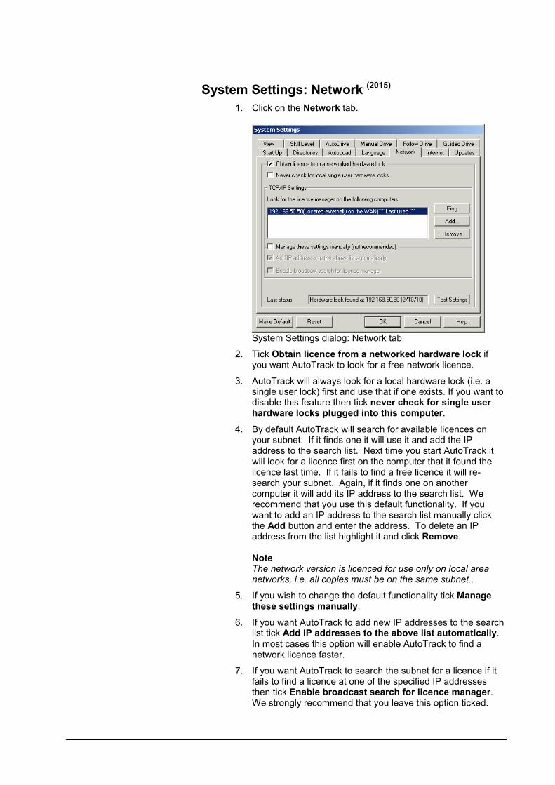
System Settings: Network (2015)
1. Click on the Network tab.
System Settings dialog: Network tab
2. Tick Obtain licence from a networked hardware lock if you want AutoTrack to look for a free network licence.
3. AutoTrack will always look for a local hardware lock (i.e. a single user lock) first and use that if one exists. If you want to disable this feature then tick never check for single user hardware locks plugged into this computer.
4. By default AutoTrack will search for available licences on your subnet. If it finds one it will use it and add the IP address to the search list. Next time you start AutoTrack it will look for a licence first on the computer that it found the licence last time. If it fails to find a free licence it will re-search your subnet. Again, if it finds one on another computer it will add its IP address to the search list. We recommend that you use this default functionality. If you want to add an IP address to the search list manually click the Add button and enter the address. To delete an IP address from the list highlight it and click Remove.
NoteThe network version is licenced for use only on local area networks, i.e. all copies must be on the same subnet..
5. If you wish to change the default functionality tick Manage these settings manually.
6. If you want AutoTrack to add new IP addresses to the search list tick Add IP addresses to the above list automatically. In most cases this option will enable AutoTrack to find a network licence faster.
7. If you want AutoTrack to search the subnet for a licence if it fails to find a licence at one of the specified IP addresses then tick Enable broadcast search for licence manager. We strongly recommend that you leave this option ticked.

User Manual for AutoTrack Settings 101
WarningIf you manage the settings manually and untick both Add IP addresses to the above list automatically and Enable broadcast search for licence manager and if there are no IP addresses in the search list or if they are wrong AutoTrack will never find a licence.
8. Click Test Settings to check that the settings can find a licence. Last status displays the results of the last search for a network licence.
Releasing network licences
Occasionally you may need to release a network licence to allow someone else to use AutoTrack on another computer.
9. To release a network licence either select Release network licence from the AutoTrack, Utilities drop down menu or select About AutoTrack from the AutoTrack, Help drop down menu and click the Release button.
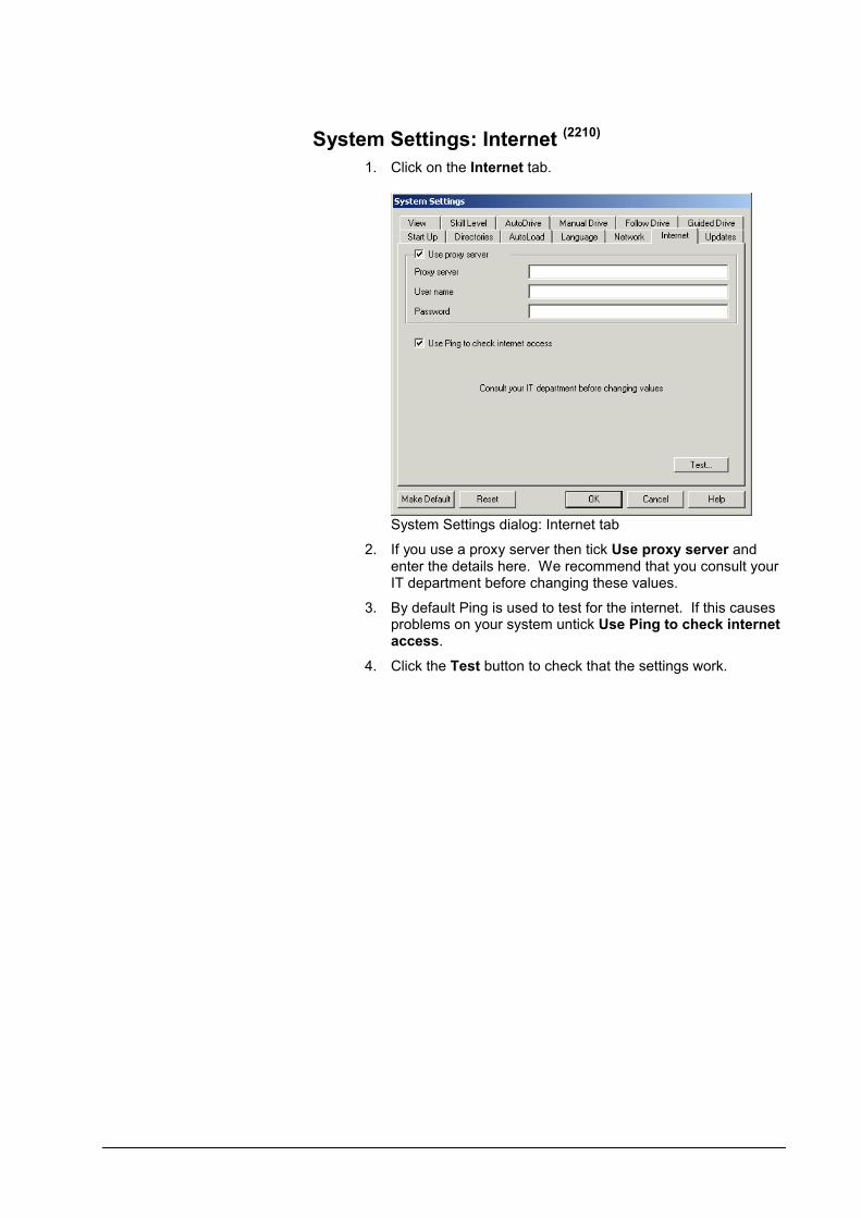
System Settings: Internet (2210)
1. Click on the Internet tab.
System Settings dialog: Internet tab
2. If you use a proxy server then tick Use proxy server and enter the details here. We recommend that you consult your IT department before changing these values.
3. By default Ping is used to test for the internet. If this causes problems on your system untick Use Ping to check internet access.
4. Click the Test button to check that the settings work.

User Manual for AutoTrack Settings 103
System Settings: Updates (2190)
AutoTrack is able to log onto the internet and check for newer versions of itself automatically at regular intervals dictated by the user. By default this feature is switched off but the user is offered the opportunity to switch it on when the first automatic check is due. Update checking may have been restricted by your system administrator.
1. Click on the Updates tab.
System Settings dialog: Updates tab
2. Click the Check for updates now button to access the internet and check for updates immediately. If an update is available the AutoTrack Updates dialog will appear. See AutoTrack Updates dialog below.
3. Tick Check for updates automatically on startup to have AutoTrack check for newer versions at regular intervals when AutoTrack is started. Note that the check is performed when AutoTrack starts and not when the CAD system starts.
4. Enter the frequency of checking in days in the Check for updates every field. If you want AutoTrack to check for updates every time you run the program set the frequency to zero.
5. Tick Remind me to install downloaded files when I start AutoTrack to be reminded, every time you start AutoTrack, if you have downloaded a newer version but not yet installed it.
Note 1If the Check for updates automatically on startup tick box is disabled automatic update checking may have been disabled by your system administrator.
Note 2If the Check for updates now button is disabled all update checking may have been disabled by your system administrator.

AutoTrack Updates dialog (1970)
1. The AutoTrack Updates dialog lists the main changes to AutoTrack since the version you are currently running.
AutoTrack Updates dialog
2. Click the Download button to download the file to the My
AutoTrack Data\Updates subdirectory of your My Documents folder. Note that while the file is downloading you will be unable to use other functions in your CAD system. Users with slow connections may therefore prefer to logon to the web site at a more convenient time.
WarningIf your company has a policy of central software control then you may have restricted access. This means that you will not be able to download the software but instead should refer to your system supervisor.
3. As soon as the download has finished, or if you have previously downloaded the new version but not yet installed it, the Install button will be enabled. Click the Install button to install the new version. The current session will be closed while the new version is installed.
4. Tick Don’t remind me again (only visible when checking was automatic) and click the Close button if you don’t want to be reminded of updates in future, i.e. to switch off automatic update checking.

User Manual for AutoTrack Settings 105
System Settings: View (2040)
1. Click on the View tab.
System Settings dialog: View tab
2. By default AutoPan moves the drawing so that the vehicle wheels are pointing directly at the centre of the screen and are positioned a distance of 50% of half the screen height from the centre of the screen. This allows you space to continue the manoeuvre. You can set the distance from the centre of the screen at which the vehicle is positioned following the pan by changing AutoPan to Distance from Centre of Screen. Set a value of 0% if you want the vehicle positioned exactly in the centre of the screen following the pan. Set 100% if you want the vehicle positioned right on the edge of the screen following the pan but be warned that in this case most of the vehicle is likely to not be visible following the AutoPan.
3. Tick AutoRotate following AutoPan if you want the drawing rotated at the same time as it is automatically panned. This does not affect behaviour if you manually invoke the pan command.
4. AutoRotate rotates the drawing so that either the spine of the tractor unit points directly up the screen. We find that this makes visualising the vehicles orientation easier when using the Manual Drive interface. However you can set AutoRotate to Bearing of to Steered Wheels if you find that more natural.
5. Tick AutoPan following AutoRotate if you also want to pan the drawing when AutoRotate is invoked.
6. Use the Grip symbol size slider to adjust the size of the editing grips.
7. Tick Show grip tips to display a text prompt alongside each grip when the cursor is over the grip.
Note

The Grip symbol size and Show grip tips settings only apply to grips displayed when using the AutoTrack editing commands. Grips displayed when the object is simply selected are controlled by the host CAD system settings.
8. Some AutoTrack features, such as manually controlled secondary steering, make use of the mouse wheel. By default in these cases we temporarily override any CAD functions that use the mouse wheel and to use the CAD function you must hold the <Ctrl> key down.
If you would rather that the CAD system had priority tick Hold <Ctrl> key down to use mouse wheel. The CAD system will then retain control of the mouse wheel unless you hold down the <Ctrl> key.
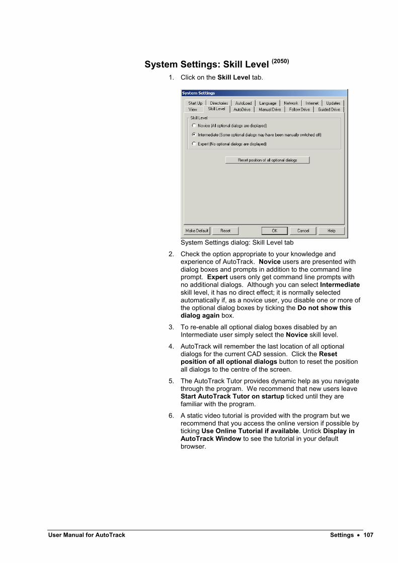
User Manual for AutoTrack Settings 107
System Settings: Skill Level (2050)
1. Click on the Skill Level tab.
System Settings dialog: Skill Level tab
2. Check the option appropriate to your knowledge and experience of AutoTrack. Novice users are presented with dialog boxes and prompts in addition to the command line prompt. Expert users only get command line prompts with no additional dialogs. Although you can select Intermediateskill level, it has no direct effect; it is normally selected automatically if, as a novice user, you disable one or more of the optional dialog boxes by ticking the Do not show this dialog again box.
3. To re-enable all optional dialog boxes disabled by an Intermediate user simply select the Novice skill level.
4. AutoTrack will remember the last location of all optionaldialogs for the current CAD session. Click the Reset position of all optional dialogs button to reset the position all dialogs to the centre of the screen.
5. The AutoTrack Tutor provides dynamic help as you navigate through the program. We recommend that new users leave Start AutoTrack Tutor on startup ticked until they are familiar with the program.
6. A static video tutorial is provided with the program but we recommend that you access the online version if possible by ticking Use Online Tutorial if available. Untick Display in AutoTrack Window to see the tutorial in your default browser.

System Settings: Paths: AutoDrive (Roads only) (2100)
1. Click on the AutoDrive tab.
System Settings dialog: AutoDrive tab
2. Tick Fast drag mode to only redraw the current point and one either side during dynamic editing. When the new point is confirmed the whole path is recalculated and redrawn. If this box is not checked the dynamic editing will be slower but more accurate.
3. Tick Default clearance envelope to show a clearance zone outside the actual body envelope (if shown) and/or wheel envelope (if shown) while the vehicle is ghosted during driving. This allows accurate control if you have fixed clearance or safety guidelines. You may edit the clearance envelope offset distance in the adjacent box.
4. Tick Default side overturn distance to make the vehicle perform a side overturn by default (i.e. turn in the opposite direction prior to starting a bearing turn). Enter the default distance that the vehicle should deviate sideways.
5. Tick Default exit overturn distance to make the vehicle perform an exit overturn by default (i.e. turn past the normal exit point prior to turning back onto the required exit bearing). Enter the default distance that the vehicle should deviate from its normal path.
6. Enter the Minimum distance between intermediate gripsto prevent too many closely spaced grips.
7. Predictive Turning mode draws path extents at the beginning of each section and envelope extents at the end of each section that help judge where to place target points. Note that the envelope extents for articulated vehicles represent not the absolute turning limits but the tightest turn possible without over-articulating. Thus it may be possible to turn tighter for a short distance.

User Manual for AutoTrack Settings 109
8. Tick Path extents at start of section to show the left and right limits to path at the last target point placed. Select and enter up to two steering percentage values. Note that these are percentages of the lesser of the maximum non-articulating steering limits and the maximum steering angle.
9. Tick Envelope extents at end of section to show the left and right limits of the body envelope at the cursor. Select and enter up to two steering percentage values. Note that these are percentages of the lesser of the maximum non-articulating steering limits and the maximum steering angle.
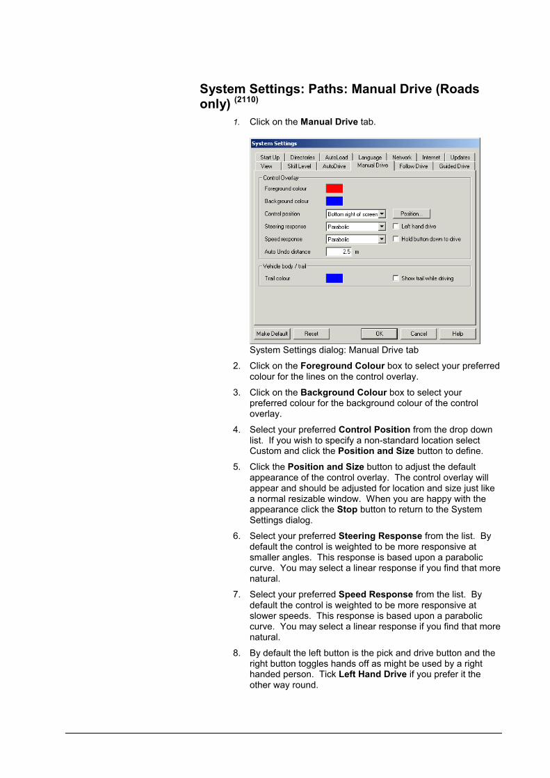
System Settings: Paths: Manual Drive (Roads only) (2110)
1. Click on the Manual Drive tab.
System Settings dialog: Manual Drive tab
2. Click on the Foreground Colour box to select your preferred colour for the lines on the control overlay.
3. Click on the Background Colour box to select your preferred colour for the background colour of the control overlay.
4. Select your preferred Control Position from the drop down list. If you wish to specify a non-standard location select Custom and click the Position and Size button to define.
5. Click the Position and Size button to adjust the default appearance of the control overlay. The control overlay will appear and should be adjusted for location and size just like a normal resizable window. When you are happy with the appearance click the Stop button to return to the System Settings dialog.
6. Select your preferred Steering Response from the list. By default the control is weighted to be more responsive at smaller angles. This response is based upon a parabolic curve. You may select a linear response if you find that more natural.
7. Select your preferred Speed Response from the list. By default the control is weighted to be more responsive at slower speeds. This response is based upon a parabolic curve. You may select a linear response if you find that more natural.
8. By default the left button is the pick and drive button and the right button toggles hands off as might be used by a right handed person. Tick Left Hand Drive if you prefer it the other way round.

User Manual for AutoTrack Settings 111
9. If you tick Hold Button Down to Drive the vehicle will only move while you are holding the mouse button down. If you untick the box the vehicle will move as soon as the cursor moves outside the stop zone.
10. The Auto Undo distance is the length of path that is erased when you click the Auto Undo button on the control overlay. You may set it to any value but do bear in mind that auto undo is non-reversible and so we suggest that you do not set a very large value.
11. Tick Show Outline Trails to show a trail as you drive (a bit like a snail!).
12. Click on the Vehicle Trail Colour box to select your preferred colour for the trails left while driving.
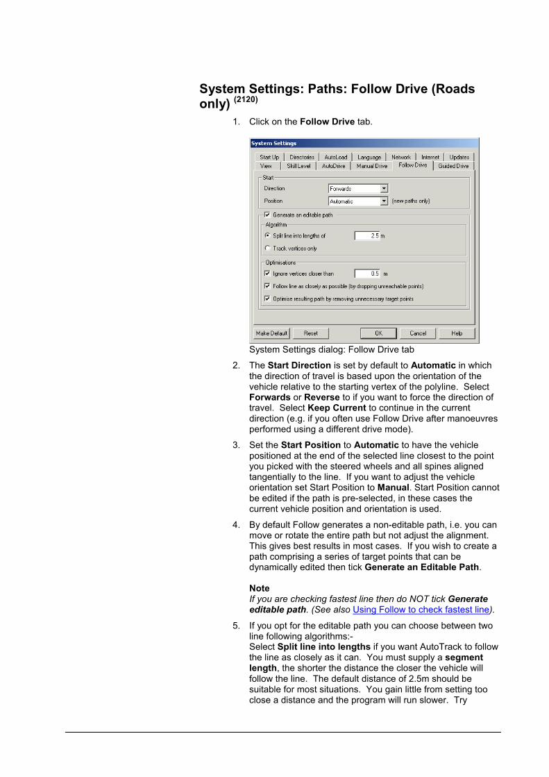
System Settings: Paths: Follow Drive (Roads only) (2120)
1. Click on the Follow Drive tab.
System Settings dialog: Follow Drive tab
2. The Start Direction is set by default to Automatic in which the direction of travel is based upon the orientation of the vehicle relative to the starting vertex of the polyline. Select Forwards or Reverse to if you want to force the direction of travel. Select Keep Current to continue in the current direction (e.g. if you often use Follow Drive after manoeuvres performed using a different drive mode).
3. Set the Start Position to Automatic to have the vehicle positioned at the end of the selected line closest to the point you picked with the steered wheels and all spines aligned tangentially to the line. If you want to adjust the vehicle orientation set Start Position to Manual. Start Position cannot be edited if the path is pre-selected, in these cases the current vehicle position and orientation is used.
4. By default Follow generates a non-editable path, i.e. you can move or rotate the entire path but not adjust the alignment. This gives best results in most cases. If you wish to create a path comprising a series of target points that can be dynamically edited then tick Generate an Editable Path.
NoteIf you are checking fastest line then do NOT tick Generate editable path. (See also Using Follow to check fastest line).
5. If you opt for the editable path you can choose between two line following algorithms:-Select Split line into lengths if you want AutoTrack to follow the line as closely as it can. You must supply a segment length, the shorter the distance the closer the vehicle will follow the line. The default distance of 2.5m should be suitable for most situations. You gain little from setting too close a distance and the program will run slower. Try

User Manual for AutoTrack Settings 113
increasing the segment length if your vehicle cannot negotiate a turn.Select Track vertices only if you want AutoTrack to use the vertices as target points. Note that this option will follow theautomatically generated vertices on splined polylines.
6. Tick Ignore vertices to allow AutoTrack to ignore closely spaced vertices. Lines can be difficult to follow if they contain many closely spaced points so we recommend that this option is used.
7. The vehicle will not always be able to reach target points on tight bends. Tick Follow line as closely as possible to allow the vehicle to wander from the line temporarily instead of stopping. The vehicle will then ignore target points that it cannot reach and focus on the next one. This has the effect of allowing the vehicle to drift out on tight bends.
8. Not all automatically inserted target points will always be necessary, i.e. no change of steering may be required. If you tick Optimise resulting path by removing unnecessary target points AutoTrack will remove targets points at which no steering changes are required.
Using Follow to check fastest line
If you want to check fastest line (e.g. through a roundabout) then you should set the design speed to the highest permitted and then create a non-editable path, i.e. do NOT tick Generate an editable path.
If AutoTrack cannot complete the path at the specified design speed then the speed will be reduced to the point at which it can. Note that if the design speed has to be reduced it will be for the entire length of the path. If you wish to check individual bends within the paths you should split the path into sections.

System Settings: Paths: Guided Drive (Rail only) (2130)
1. Click on the Guided Drive tab.
System Settings dialog: Guided Drive tab
2. The Start Direction is set by default to Forwards.

User Manual for AutoTrack Settings 115
Drawing SettingsThe AutoTrack Drawing Settings control those aspects of the system that are drawing related. The drawing settings are displayed all at once on a single tabbed dialog.
Drawing Settings button
1. Select Drawing Settings from the AutoTrack drop down menu or click the Drawing Settings button on the AutoTrack toolbar or type ATRADRAWINGSETTINGS at the command line. The Drawing Settings dialog will appear.
Drawing Settings dialog
2. Click the appropriate tab to edit or view the settings.
3. Edit the data as required and click OK to confirm when you are satisfied. Click Cancel to abort all changes and close the Drawing Settings dialog.
4. Click Make Default to save the displayed settings as defaults for the next session. Click Reset to restore your last saved default settings following changes.

Drawing Settings: Units (2020)
1. Click on the Units tab.
Drawing Settings dialog: Units tab
2. You can use different units for vehicle editing and viewing and for reporting. Select the units that you wish to use for Distance, Angles, Speed and Time.

User Manual for AutoTrack Settings 117
Drawing Settings: Scale (2030)
1. Click on the Scale tab.
Drawing Settings dialog: Scale tab
2. AutoCADSet the drawing units and scale by entering the number of distance units that 1 Drawing Unit representsfollowed by the units. If you set this incorrectly your vehicles will appear at the wrong size relative to other objects.
MicroStationSet the drawing units and scale by entering the number of distance units that 1 Master Unit represents followed by the units. If you set this incorrectly your vehicles will appear at the wrong size relative to other objects.
3. Tick Auto check scale against drawing extents to have AutoTrack perform a crude scale check on existing drawings when the vehicle is positioned for the first path in a new drawing. This is a useful reminder if you have not set the drawing units and/or scale correctly.
4. Tick Prompt scale before use to have AutoTrack prompt you for a scale on new drawings. Note that this box is ticked by default for Novice users.
5. The middle frame labeled Angles contains values that are read from your CAD system settings and cannot be edited here. If you need to change these settings, do so through your CAD system.
6. Driving convention determines the position of a driver or pilot if defined and therefore vehicle tracking if the tracking point is set to pilot/driver. It also affects the direction of angled parking bays according to direction of traffic flow if you are using the parking tools.

Drawing Settings: Paths: Layers (AutoCAD only) (2060)
NoteMicroStation users should refer to the next sections, Drawing Settings: Levels (MicroStation v8 onwards) and Drawing Settings: Levels (MicroStation pre-v8 only).
1. Click on the Layers tab.
Drawing Settings dialog: Layers tab
2. Tick Use a layer naming convention if you want AutoTrack to automatically place the entities that you create on separate logical named layers (strongly recommended).
3. If you opt not to use a layer naming convention all new paths will be placed on the current layer.
4. Select one of the Savoy conventions or the AEC BS1192 Part 5 layer naming convention. See below for details of all the layer naming conventions.
5. Tick Prompt before creating new layers to have AutoTrack warn before new layers are created. In practice this means you will be prompted with a default layer name before you start each new path (see Base Layer Name dialog below) and given the opportunity to change it.
6. By default AutoTrack construction lines are not plotted. If you want to them to appear on output plots tick Plot construction lines.
Note Adoption of a layer naming convention does not prevent you from renaming a layer later.

User Manual for AutoTrack Settings 119
Drawing Settings: Paths: Levels (MicroStation v8 onwards) (2067)
NoteMicroStation pre-v8 users should refer to the next sectionDrawing Settings: Levels (MicroStation pre-v8 only).
1. Click on the Levels tab.
Drawing Settings dialog: Levels tab
2. Tick Use a level naming convention if you want AutoTrack to automatically place the entities that you create on separate logical named levels (strongly recommended).
3. If you opt not to use a level naming convention all new paths will be placed on the current level.
4. Select one of the Savoy conventions or the AEC BS1192 Part 5 level naming convention. See below for details of all the level naming conventions.
5. Tick Prompt before creating new levels to have AutoTrack warn before new levels are created. In practice this means you will be prompted with a default level name before you start each new path (see Base Level Name dialog below) and given the opportunity to change it.
6. The option to Plot construction lines is not available in MicroStation because that CAD system has a similar feature built-in.
Note Adoption of a level naming convention does not prevent you from renaming a level later.

Drawing Settings: Paths: Levels (MicroStation pre-v8 only) (2065)
NoteUsers of MicroStation v8 or later should refer to the previous section Drawing Settings: Levels (MicroStation v8 onwards).
1. Click on the Levels tab.
Drawing Settings dialog: Levels tab
2. Select the level on which you want AutoTrack to place new paths.
NoteSetting the report level does not change the active level.

User Manual for AutoTrack Settings 121
Layer / Level naming conventions
AutoTrack has four built in layer or level naming conventions.
Savoy Basic Layer/Level naming convention
Under the Savoy basic naming convention all path and report data is placed on a single layer or level named:-
ATRxx
where:-
xx is the path number
Note that this is also the base layer or level name for the other Savoy naming conventions.
The path and all report elements have explicitly defined colours and line types. Their colours and line types cannot therefore be changed by changing layer or level settings.
Parking bays are placed on layers named Bays and parking islands on a layer called Islands.
Savoy Standard Layer/Level naming convention
Under the Savoy standard naming convention the path data and construction lines are placed on layers or levels named:-
ATRxx
and each report is placed on a layer or level named:-
ATRxxRyy
where:-
xx is the path number
yy is the report number
The path and all report elements have explicitly defined colours and line types. Their colours and line types cannot therefore be changed by changing layer or level settings.
Parking data is placed on layers as per the basic convention except that construction lines are now separated and placed on a layer called BayConstruction.
Savoy Complex Layer/Level naming convention
Under the Savoy complex naming convention the layers or levels are named as follows:-
ATRxxRyyrd
where:-
xx is the path number
yy is the report number (on this path)
r is the report subject (Body, Chassis, Path, Symbols, Text)
d is the direction of travel of the vehicle (Forward or Reverse).

NoteThe direction is not used on reports that use a single layer or level.
The path and all report elements have explicitly defined colours and line types. Their colours and line types cannot therefore be changed by changing layer or level settings.
Each different type of parking data is placed on a different layer, e.g. privacy posts are placed on a layer called PrivacyPosts. In addition each type of construction line is placed on its own layer, e.g. flow direction arrows are placed on a layer called RowFlowDirection.
AEC BS1192 Part 5 Layer/Level naming Convention
Under the AEC naming convention the layers or levels are named as follows:-
V070PX$??GBATRxxRyyrd
where:-
?? is the current elevation (00 if none found)
xx is the path number
yy is the report number (on this path)
r is the report subject (Body, Chassis, Path, Symbols, Text)
d is the direction of travel of the vehicle (Forward or Reverse).
NoteThe direction is not used on reports which use a single layer or level.
The default discipline code (V) (which is not listed in the AEC disciplines) has been chosen because AutoTrack is used by professionals from a wide range of disciplines and this code allows the AutoTrack vehicle data to be isolated. Likewise the part code is normally discipline dependent so an unallocated code (070) has been selected for use here. Finally, pen colour or type is user dependent so code P is used here. All layer names can be edited if required.
The path and all report elements have explicitly defined colours and line types. Their colours and line types cannot therefore be changed by changing layer or level settings.
Parking data is placed on the same layers as the Savoy Complex convention.
Base layer or level name (Base Layer/Level Name dialog) (5120)
The base layer or level name is the part of the name to which is appended the sub-text appropriate to the selected naming convention. Thus if you use the Standard Savoy naming convention and change the default base layer/level name to BASENAME the layers or levels generated will be of the form…
BASENAMERyyrd
instead of… ATRxxRyyrd

User Manual for AutoTrack Settings 123
Drawing Settings: Paths: Tracking Point (Roads& Airports) (2170)
1. The path travelled by the vehicle is the line connecting the target points travelled by a specified tracking point on the vehicle. A tracking point on the first unit of the vehicle is used when the vehicle is travelling forwards and a point on the last unit when it is reversing. The tracking point is also the point that follows the line in the Follow drive mode.
2. Click on the Tracking Point tab.
Drawing Settings dialog: Tracking Point tab
3. Set the Forwards Tracking Point to the point you wish to track while the vehicle is moving forwards. Note that some of the options require you to select left or right using the adjacent drop down list box. With the exception of Pilot / Driver and User Defined Point the tracking point is assumed to be on the centre line of the unit. Note that front tracking points on a front steered vehicle tend to give better results that rear tracking points.
4. If you want to specify a point offset from the centre line then tick Offset to the left or Offset to the right as appropriate and enter the offset distance.
5. If you want to specify a particular point the set the Tracking Point to User Defined Point and enter the coordinates explicitly. X is measured from the front coupling or, if there is no front coupling, from the front axle, increasing positive towards the back of the unit; and Y is measured positive to the right of the centre line.
6. If you are modeling aircraft using Follow you should set this to Pilot / Driver or Cockpit if you want to simulate pilot’s eye tracking.

7. The Reverse Tracking Point, the point that you want to track while the vehicle is moving backwards, is set in exactly the same way.
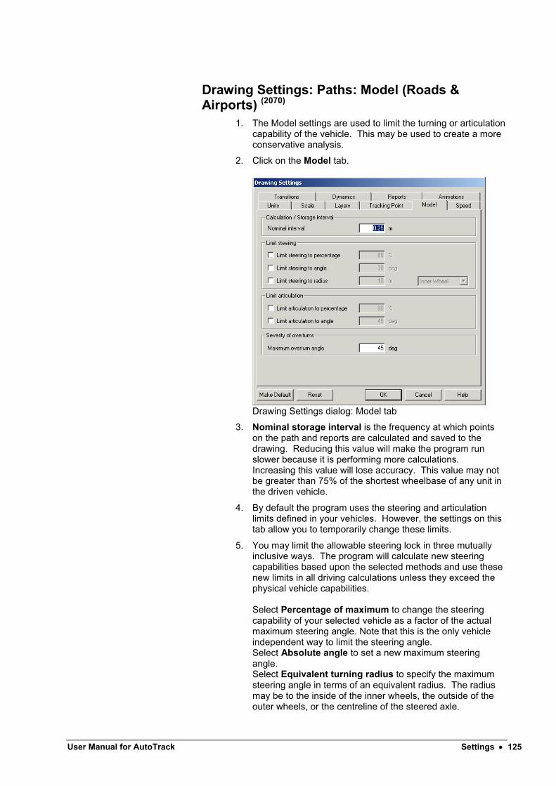
User Manual for AutoTrack Settings 125
Drawing Settings: Paths: Model (Roads & Airports) (2070)
1. The Model settings are used to limit the turning or articulation capability of the vehicle. This may be used to create a more conservative analysis.
2. Click on the Model tab.
Drawing Settings dialog: Model tab
3. Nominal storage interval is the frequency at which points on the path and reports are calculated and saved to the drawing. Reducing this value will make the program run slower because it is performing more calculations. Increasing this value will lose accuracy. This value may not be greater than 75% of the shortest wheelbase of any unit in the driven vehicle.
4. By default the program uses the steering and articulation limits defined in your vehicles. However, the settings on this tab allow you to temporarily change these limits.
5. You may limit the allowable steering lock in three mutually inclusive ways. The program will calculate new steering capabilities based upon the selected methods and use these new limits in all driving calculations unless they exceed the physical vehicle capabilities.
Select Percentage of maximum to change the steering capability of your selected vehicle as a factor of the actual maximum steering angle. Note that this is the only vehicle independent way to limit the steering angle.Select Absolute angle to set a new maximum steering angle.Select Equivalent turning radius to specify the maximum steering angle in terms of an equivalent radius. The radius may be to the inside of the inner wheels, the outside of the outer wheels, or the centreline of the steered axle.

6. You may limit the allowable articulation angles in two mutually inclusive ways. The program will calculate new articulation capabilities for all units based upon this figure and use these new limits in all driving calculations unless they exceed the physical vehicle capabilities.
Select Percentage of maximum to change the articulation limits of your selected vehicle as a factor of the actual maximum articulation angle. Note that this is the only vehicle independent way to limit articulation angles.Select Absolute angle to set a new maximum articulation angle.
7. Overturns are when the vehicle turns sideways in the opposite direction prior to making a turn or when the vehicle continues forwards and turns late. Both are performed to minimize cut-in. The Maximum overturn angle is a way to limit the severity of the overturn by restricting the angle of deviation from a “normal” path.

User Manual for AutoTrack Settings 127
Drawing Settings: Paths: Speed (Roads, Rail & Airports) (2080)
1. The design speed affects controls how fast the manouevre is animated and may also affect the shape of turns on some versions of AutoTrack if a speed dependent turn transition is enabled.
2. Click on the Speed tab.
Drawing Settings dialog: Speed tab
3. You may specify different values for the Forward design speed and Reverse design speed since typically you would travel slower in reverse. Note that the vehicle movement will always be modeled at the design speed regardless of the rate at which you choose to animate the manoeuvre on screen.
WarningIf you are modelling turns at speeds greater than 15kph we strongly recommend that you limit the turn radius. Go to either the Model tab or the Dynamics tab.

Drawing Settings: Paths: Transitions (Roads & Airports) (2085)
1. The Transitions settings control how fast the steering angle changes into and between turns.
2. Click on the Transitions tab.
3.Drawing Settings dialog: Transitions
4. By default the rate at which the steering can be turned is limited. This reflects the real life situation in which the vehicle is moving whilst steering lock is being applied. Tick Limit forward turn rate and/or Limit reverse turn rate to prevent instantaneous application of lock while travelling forwards or backwards respectively. Note that this setting can also be changed during driving if necessary.
NoteDisabling turn rates is equivalent to the use of the Turn on the Spot feature in version 2 of AutoTrack.
5. The steering turn rate can be limited in one of three ways. Either by defining the speed of the vehicle which is then used in conjunction with the vehicles lock to lock time or, by explicitly defining the lock to lock distance (i.e. the distance travelled in the lock to lock time), or by the pure geometric calculation of a circular arc.
Select Based upon lock to lock time to impose a turn rate that causes the turn radius to increase with speed. The turn rate (degrees per unit of distance) will be calculated as follows:-R = A / V t
Select Based upon lock to lock distance to impose a limit that is fixed for all speeds. The turn rate (degrees per unit of distance) will be calculated as follows:-

User Manual for AutoTrack Settings 129
R = A / d
Where:-R is Max Turn RateA is Max Steering AngleV is Design Speed
t is Lock to Lock Timed is Lock to Lock Distance
Select Based upon circular tangential arc if you want the tracking point (typically the centre of the steered wheels) to follow a perfectly circular arc irrespective of speed or lock to lock time. Note that this is the model used by several organisations to generate design vehicle turn templates (e.g. AASHTO, TAC). This mode can only be used with tracking points that are in front of (relative to the direction of motion) the minimum cut-in point.
6. The turn transitions can also be disabled automatically at changes of direction. Tick Turn on the spot at start of all forwards sections to automatically disable turn transitions when you stop reversing and start travelling forwards or Turn on the spot at start of all reverse sections to disable them when to stop travelling forwards and start reversing.
7. Finally, to force AutoTrack to set the best possible starting steering angle at just the start of the path tick Set optimum steering angle at start of path.
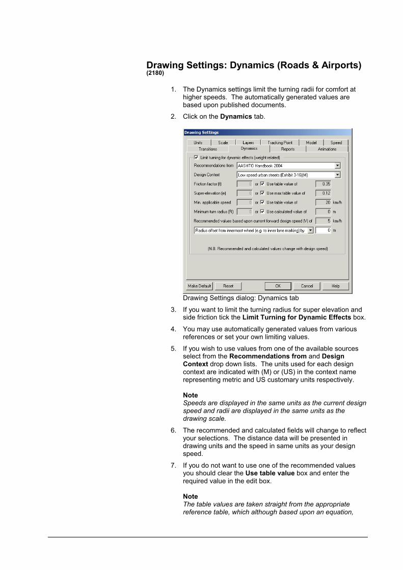
Drawing Settings: Dynamics (Roads & Airports) (2180)
1. The Dynamics settings limit the turning radii for comfort at higher speeds. The automatically generated values are based upon published documents.
2. Click on the Dynamics tab.
Drawing Settings dialog: Dynamics tab
3. If you want to limit the turning radius for super elevation and side friction tick the Limit Turning for Dynamic Effects box.
4. You may use automatically generated values from various references or set your own limiting values.
5. If you wish to use values from one of the available sources select from the Recommendations from and Design Context drop down lists. The units used for each design context are indicated with (M) or (US) in the context name representing metric and US customary units respectively.
NoteSpeeds are displayed in the same units as the current design speed and radii are displayed in the same units as the drawing scale.
6. The recommended and calculated fields will change to reflect your selections. The distance data will be presented in drawing units and the speed in same units as your design speed.
7. If you do not want to use one of the recommended values you should clear the Use table value box and enter the required value in the edit box.
NoteThe table values are taken straight from the appropriate reference table, which although based upon an equation,

User Manual for AutoTrack Settings 131
may be rounded. If you choose to use any of your own values AutoTrack will use the base equation to calculate the recommended limiting turn radius. This means that you may get slightly different values if you manually enter a value that is the same as a recommended value.
8. The Side friction factor (f) is the ratio of the force parallel to the road surface and the reaction perpendicular to the road surface and the recommended values are all based upon comfort limits rather than physical skidding limits.
9. The Super elevation (e) is the slope of the road surface at right angles to the direction of vehicle travel. It is expressed as a factor so 2% super elevation should be entered as 0.02.
10. The table values are used for all speeds above a Min. applicable speed (V) which is the lowest speed listed in each table.
11. The recommended Minimum turn radius (R) that is displayed relates to the current forward design speed (which is shown on the same dialog). The values used will change as you vary the speed. They do not apply in reverse. AutoTrack will use the value listed in a table if the current forward design speed is within 0.5kph. If the design speed is outside this tolerance then the limiting radius will be calculated direct using the curve formulae relevant to the design publication and context.
The equation used for limiting values of e and f is:-
R = V2 / 127(e+f)
Where:-R is Minimum Turn RadiusV is Design Speede is Maximum Super-elevation (expressed as m/m)f is Side Friction Factor
If the sum of super elevation and side friction factor is zero the minimum turn radius will not be calculated.
The radius relates either to the outermost wheel track, the innermost wheel track or the centre of the steered wheels. Select it from the drop down list box. The defaults for this field vary according to the selected table and are based upon advice from AASHTO representatives. If you select Radius is offset from outermost wheel track or Radius is offset from innermost wheel track then the calculated limiting wheel angle is based upon the path the vehicle must steer to keep the wheels just within the outer lane marking or just outside the inner lane marking respectively. In reality you will probably want to model the vehicle travelling some distance away from the lane marking to avoid collisions with vehicles in adjacent lanes or oncoming vehicles. Enter the clearance between the vehicle wheel envelope and the lane marking in the edit box provided.
AutoTrack will prevent a vehicle from using the limiting radius if it is lower than its design capabilities.
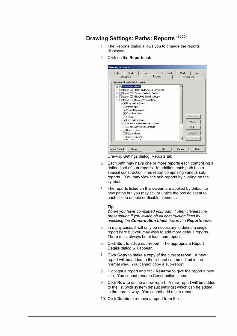
Drawing Settings: Paths: Reports (3000)
1. The Reports dialog allows you to change the reports displayed.
2. Click on the Reports tab.
Drawing Settings dialog: Reports tab
3. Each path may have one or more reports each comprising a defined set of sub-reports. In addition each path has a special construction lines report comprising various sub-reports. You may view the sub-reports by clicking on the + symbol.
4. The reports listed on this screen are applied by default to new paths but you may tick or untick the box adjacent to each title to enable or disable elements.
TipWhen you have completed your path it often clarifies the presentation if you switch off all construction lines by unticking the Construction Lines box in the Reports view.
5. In many cases it will only be necessary to define a single report here but you may wish to add more default reports. There must always be at least one report.
6. Click Edit to edit a sub-report. The appropriate Report Details dialog will appear.
7. Click Copy to make a copy of the current report. A new report will be added to the list and can be edited in the normal way. You cannot copy a sub-report.
8. Highlight a report and click Rename to give the report a new title. You cannot rename Construction Lines.
9. Click New to define a new report. A new report will be added to the list (with system default settings) which can be edited in the normal way. You cannot add a sub-report.
10. Click Delete to remove a report from the list.

User Manual for AutoTrack Settings 133
Drawing Settings: Paths: Construction Lines (3160)
1. Construction Lines may prove useful whilst creating the path but would normally be disabled for the final report.
2. Click on the appropriate tab and tick the Show… box of those elements that you want.
Drawing Settings: Construction Lines
3. The following applies to all six types of construction lines. However, there are some options that apply only to particular types. These are listed at the end.
4. Path is the locus of the tracking point. Errored Path is a line connecting the target points of those sections of the path that cannot be performed.Model Changes are represented by an octagonal symbol and include speed changes and changes to the transition type.Target Points are shown as small crosses.Drag Lines are shown connecting the driving grip and the centres of the front and rear axles.Steering Pointer is a line or arrow projecting from the centre of the steered axle a distance equal to the wheelbase of the unit.
5. Select the Colour from the drop down list box. 255 pen colours are listed. To use a colour that is not listed select Custom and click on the colour swatch to select from a colour chart.
AutoCAD onlyThe pen numbers directly correlate with AutoCAD’s pen numbering system (colour indices in later versions). If you select a custom colour that does not correspond to a defined pen colour it will be treated as TrueColor.
6. Select the Line Type from the drop down list box.
7. Enter a line Weight for the report. 0.0mm is the default and forces the thinnest possible line. Wider lines are drawn symmetrically about the centreline. (Not available in AutoCAD R14).
NoteVariations in line weight are only visible on printed output or in a print preview.
Drawing Settings: Construction Lines: Path
1. Select Show path line to display the path of the tracking point.
2. Select Show path identifier to display the path number adjacent to each path.
Drawing Settings: Construction Lines: Drag Lines
1. Select Show overturn draglines to display editing draglines at overturns.
2. Select Show extend path draglines to display draglines extending from the front and rear of the vehicle. These may be used to extend the path by one section at a time.
Drawing Settings: Construction Lines: Steering Pointer
1. Select Show steering percentage to display the physical steering angle as a percentage of the maximum possible.
2. Select Use simple steering pointer to display the steering pointer as a line instead of as an arrow.

User Manual for AutoTrack Settings 135
Drawing Settings: Paths: Reports: Discrete (3020)
1. This controls the appearance of the discrete outlines sub-report. It is applicable to various report types, including body, chassis, loads, etc. Each different report type may have different settings for its discrete sub-report.
2. Click on the Discrete tab.
Body Outlines Report dialog: Discrete tab (other discrete outline reports similar)
3. Tick Show Discrete Outlines to enable this element.
4. Tick the boxes to specify the features that you want.
The option At all Discrete Body Outlines is available on all but the Body Outline sub-report.
The option Use simple body outline is only available on the discrete and spaced body outline reports. It uses the outlines defined in the vehicle's Body Outline (Plan) outline type instead of those in Body Detail (Plan).
The option to display Label Text is only available on the Annotation report. Leave the Label Text field blank to display the vehicle name; the text - Vehicle Name - will automatically appear in the edit box.
5. Tick At Offsets to show outlines at specified positions. Enter the distances from the start of the path in the adjacent box. You should use commas to separate distances, e.g. 10.4, 15.6, 23.9 would draw body outlines at distances of 10.4, 15.6, and 23.9 in the current units. Click the Pick button to select positions graphically.
TipYou may find it easier to use the Place Outline command to position outlines at irregular offsets. (see Placing discrete body outlines)
6. Tick Show driver / pilot to display an icon representing the driver’s location. Note that the position of the driver can be adjusted in the vehicle details.
7. If you are using a layering convention then you will not be allowed to specify the report Layer (Level on MicroStation). Otherwise, you may select from the existing layers or specify a new layer for the report.
8. Select the Line Type from the drop down list.
9. Select the Colour from the drop down list box. 255 pen colours are listed. To use a colour that is not listed select Custom and click on the colour swatch to select from a colour chart.
AutoCAD onlyThe pen numbers directly correlate with AutoCAD’s pen numbering system (colour indices in later versions). If you select a custom colour that does not correspond to a defined pen colour it will be treated as TrueColor.
10. Enter a line Weight for the report. 0.0mm is the default and forces the thinnest possible line. Wider lines are drawn symmetrically about the centreline. (Not available in AutoCAD R14).
NoteVariations in line weight are only visible on printed output or in a print preview.
11. Tick Fill to solid fill the body outlines (AutoCAD versions only).
User Manual for AutoTrack Settings 137
Drawing Settings: Paths: Reports: Spaced (3030)
1. This controls the appearance of the spaced outlines sub-report. It is applicable to various report types, including body, chassis, loads, etc. Each different report type may have different settings for its spaced sub-report.
2. Click on the Spaced tab.
Body Outlines Report dialog: Spaced tab(other spaced outline reports similar)
3. Tick Show Evenly Spaced Outlines to enable this element.
4. Tick the boxes to specify the features that you want.
The option Use simple body outline is available on only the discrete and spaced body outline reports. It uses the outlines defined in the vehicle's Body Outline (Plan) outline type instead of those in Body Detail (Plan).
The option to display Label Text is available only on the Annotation report. Leave the Label Text field blank to display the vehicle name; the text - Path Number - will automatically appear in the edit box.
5. Enter the required Nominal Spacing for the outlines. This will place outlines at the closest stored position after the specified distance.
6. If you want the spacing to be precise instead of approximate tick Insert outlines at exact spacing. However, note thatsince the vehicle orientation must be interpolated, it may be very slightly inaccurate. Therefore, for best accuracy, we recommend that you use nominal spacing.
7. Tick Show driver / pilot to display an icon representing the driver’s location. Note that the position of the driver can be adjusted in the vehicle details.
8. If you are using a layering convention then you will not be allowed to specify the report Layer (Level on MicroStation). Otherwise, you may select from the existing layers or specify a new layer for the report.

9. Select the Line Type from the drop down list.
10. Select the Colour from the drop down list box. 255 pen colours are listed. To use a colour that is not listed select Custom and click on the colour swatch to select from a colour chart.
AutoCAD onlyThe pen numbers directly correlate with AutoCAD’s pen numbering system (colour indices in later versions). If you select a custom colour that does not correspond to a defined pen colour it will be treated as TrueColor.
11. Enter a line Weight for the report. 0.0mm is the default and forces the thinnest possible line. Wider lines are drawn symmetrically about the centreline. (Not available in AutoCAD R14).
NoteVariations in line weight are only visible on printed output or in a print preview.
12. Tick Fill to solid fill the body outlines (AutoCAD versions only).

User Manual for AutoTrack Settings 139
Drawing Settings: Paths: Reports: Loci (3040)
1. This controls the appearance of the loci sub-report. It is applicable to various report types, including body, chassis, loads, etc. Each different report type may have different settings for its loci sub-report.
2. Click on the Loci tab.
Body Outlines Report dialog: Loci tab(other loci reports similar)
3. Tick Show Loci / Tracks to enable this element.
4. The Body outline report has an option Only loci critical points. Tick this option to trace only the front offside corners of the body and the cut-in points on each side.
5. The Chassis report has an option Show outermost tyre tracks. Tick this option to show the path of the inside face of the outermost tyres, i.e. if the vehicle has twin wheels then only the outer one is tracked.
6. If you are using a layering convention then you will not be allowed to specify the report Layer (Level on MicroStation). Otherwise, you may select from the existing layers or specify a new layer for the report.
7. Select the Line Type from the drop down list.
8. Select the Colour from the drop down list box. 255 pen colours are listed. To use a colour that is not listed select Custom and click on the colour swatch to select from a colour chart.
AutoCAD onlyThe pen numbers directly correlate with AutoCAD’s pen numbering system (colour indices on later versions). If you select a custom colour that does not correspond to a defined pen colour it will be treated as TrueColor.
9. Enter a line Weight for the report. 0.0mm is the default and forces the thinnest possible line. Wider lines are drawn symmetrically about the centreline. (Not available in AutoCAD R14).

NoteVariations in line weight are only visible on printed output or in a print preview.

User Manual for AutoTrack Settings 141
Drawing Settings: Paths: Reports: Envelope (3050)
1. This controls the appearance of the envelope sub-report. It is applicable to various report types, including body, chassis, loads, etc. Each different report type may have different settings for its envelope sub-report.
2. Click on the Envelope tab.
Body Outlines Report dialog: Envelope tab(other envelope reports similar)
3. Tick Show Envelope to display an envelope of the movement of the vehicle.
4. Tick Close Envelope to join the left and right boundaries at the front and the back.
5. Tick Hatch Envelope to fill the envelope with hatch lines of the same type as the envelope itself.
6. Hatch spacing defaults to a value appropriate to the size of the vehicle, i.e. large vehicles such as aircraft will have a wider spacing than smaller vehicles such as cars.
7. The colour of the hatching is always a proportion of the envelope colour. By default, if the envelope colour is bright green the hatch colour will be dark green. The Hatch Colour Factor may be set to change this. A value of 100 represents 100% of the envelope colour, i.e. the same colour as the envelope.
8. Set the Hatch Angle to adjust the appearance of the hatching and allow overlain hatched areas to be visible.
9. Tick Cross hatch in reverse to hatch the envelope for reverse sections of the path in the opposite direction to the forwards sections.
10. If you are using a layering convention then you will not be allowed to specify the report Layer (Level on MicroStation). Otherwise, you may select from the existing layers or specify a new layer for the report.
11. Select the Line Type from the drop down list.
12. Select the Colour from the drop down list box. 255 pen

colours are listed. To use a colour that is not listed select Custom and click on the colour swatch to select from a colour chart.
AutoCAD onlyThe pen numbers directly correlate with AutoCAD’s pen numbering system (colour indices on later versions). If you select a custom colour that does not correspond to a defined pen colour it will be treated as TrueColor.
13. Enter a line Weight for the report. 0.0mm is the default and forces the thinnest possible line. Wider lines are drawn symmetrically about the centreline. (Not available in AutoCAD R14).
NoteVariations in line weight are only visible on printed output or in a print preview.
14. Tick Fill to solid fill the envelope (AutoCAD versions only).

User Manual for AutoTrack Settings 143
Drawing Settings: Paths: Reports: Offset Envelope 1
NoteOffset Envelope 2 is similar.
1. These control the appearance of each of the offset envelope sub-reports. They are applicable to various report types, including body, chassis, loads, etc. Each different report type may have different settings for its offset envelope sub-report.
2. Click on the Offset Envelope 1 tab.
3. Tick Show Body Offset Envelope 1 to add a clearance or safety envelope around the static envelope.
4. Enter a value for Offset from actual envelope. Note the default values are arbitrary.
5. Tick Close Envelope to join the left and right boundaries at the front and the back.
6. Tick Hatch Envelope to fill the envelope with hatch lines of the same type as the envelope itself.
7. Hatch spacing defaults to a value appropriate to the size of the vehicle, i.e. large vehicles such as aircraft will have a wider spacing than smaller vehicles such as cars.
8. The colour of the hatching is always a proportion of the envelope colour. For example, if the envelope colour is bright green the hatch colour will be dark green. The Hatch Colour Factor may be set to change this. A value of 100 represents 100% of the envelope colour, i.e the same colour as the envelope.
9. Set the Hatch Angle to adjust the appearance of the hatching and allow overlain hatched areas to be visible.
10. Tick Cross hatch in reverse to hatch the envelope for reverse sections of the path in the opposite direction to the forwards sections.
11. If you are using a layering convention then you will not be allowed to specify the report Layer (Level on MicroStation). Otherwise, you may select from the existing layers or specify a new layer for the report.
12. Select the Line Type from the drop down list.
13. Select the Colour from the drop down list box. 255 pen colours are listed. To use a colour that is not listed select Custom and click on the colour swatch to select from a colour chart.
AutoCAD onlyThe pen numbers directly correlate with AutoCAD’s pen numbering system (colour indices on later ersions). If you select a custom colour that does not correspond to a defined pen colour it will be treated as TrueColor.
14. Enter a line Weight for the report. 0.0mm is the default and forces the thinnest possible line. Wider lines are drawn symmetrically about the centreline. (Not available in

AutoCAD R14).
NoteVariations in line weight are only visible on printed output or in a print preview.
15. Tick Fill to solid fill the envelope (AutoCAD versions only).

User Manual for AutoTrack Settings 145
Drawing Settings: Paths: Reports: Profile (3060)
1. The Profile report settings control the appearance of the side elevation or profile report.
2. Click on the Profile tab.
Vehicle Profile Report dialog
3. The position of the diagram can be set either relative to the start of the path or explicitly. Tick Offset from start of pathfor the former and leave it unticked to fix the position explicitly. To select the location interactively click the Pickbutton, position the report and left click to confirm.
4. If you would rather see a plan view of the vehicle, instead of an elevation, then tick Show plan view of vehicle.
5. Tick the Show dimensions and vehicle details if you want an annotated diagram. Set the Dimensions font height in real world units, i.e. drawing units. If you only want dimensions then set the Vehicle details font height to zero. Likewise if you only want vehicle details.
6. If you are using a layering convention then you will not be allowed to specify the report Layer (Level on MicroStation). Otherwise, you may select from the existing layers or specify a new layer for the report.
7. Select the Line Type from the drop down list.
8. Select the Colour from the drop down list box. 255 pen colours are listed. To use a colour that is not listed select Custom and click on the colour swatch to select from a colour chart.
AutoCAD onlyThe pen numbers directly correlate with AutoCAD’s pen numbering system (colour indices in later versions). If you select a custom colour that does not correspond to a defined pen colour it will be treated as TrueColor.
9. Enter a line Weight for the report. 0.0mm is the default and forces the thinnest possible line. Wider lines are drawn symmetrically about the centreline. (Not available in AutoCAD R14).

NoteVariations in line weight are only visible on printed output or in a print preview.

User Manual for AutoTrack Settings 147
Drawing Settings: Paths: Reports: Graph (3070)
1. This controls the appearance of the steering and articulation angles graph.
2. Click on the Graph tab.
Steering/Articulation Graph Report dialog
3. The position of the diagram can be set either relative to the start of the path or explicitly. Tick Offset from start of pathfor the former and leave it unticked to fix the position explicitly. To select the location interactively click the Pickbutton, position the report and left click to confirm.
4. The height and width can be set explicitly or to be scaled with the rest of the drawing. Select Height / Width to set explicitly or Y-Scale / X-Scale to allow the graph to scale. In each case you will need to enter suitable values for height and width.
5. Enter Text height (Min and Max). Tick Scale font size if you want the text to scale with the rest of the drawing.
6. Tick Show grid lines to display a regular background grid. Adjust the spacing in each direction if necessary. Click on the button to change the line attributes.
7. Tick Show axes to draw graph axes in a different colour. Tick Show origin to draw a circle at the graph origin. Click on the button to change the line attributes.
8. Tick Show bounding box to enclose the graph in a box. Tick Show leader line to draw a line connecting the bounding box to the path. Note that the position of the connecting line is automatic and cannot be manually controlled. Click on the button to change the line attributes.
9. Tick Show steering to plot a graph of the steering angle. Tick Show max angle to draw a line representing the

maximum steering angle. Click on the button to change the line attributes.
10. Tick Show secondary steering to plot a graph of the angles of any manually controlled secondary steered axles. Tick Show max angle to draw a line representing the maximum secondary steering angle. Click on the button to change the line attributes.
11. Tick Show linked steering to plot a graph of the angles of any linked steered axles. Click on the button to change the line attributes.
12. Tick Show articulation to plot a graph of the articulation angle(s). Tick Show max articulation to draw a line(s) representing the maximum articulation angle(s). Click on the button to change the line attributes.
13. Tick Show section lines to draw vertical lines on the graph at every model change (i.e. change of speed, steering limit, etc). Tick Show speed to indicate the speed and direction along the bottom of the graph. Click on the button to change the line attributes.
14. Tick Show discrete body positions to draw vertical lines whereever a discrete body outline has been placed on the path. Tick Show leader line to draw lines connecting the path to the graph at each discretely placed body outline. Click on the button to change the line attributes.
15. Tick Label peaks to annotate the graph to showing the angle at every maximum in each direction. Tick Show % of maxangles to also show this angle expressed as a percentage of the maximum. Click on the button to change the line attributes.
User Manual for AutoTrack Settings 149
Drawing Settings: Paths: Animations (not Roads) (2150)
1. The Animations settings control the appearance of animations.
2. Click on the Animations tab.
Drawing Settings dialog: Animations tab
3. By default AutoTrack automatically sets the 3D viewing angle. If you would prefer to set the viewing angle manually then untick Set 3D viewpoint automatically.
4. The viewing angle is set by default to 30 degrees. If you would prefer a different viewing angle then select an angle from the drop down list or enter an alternative.
5. If you want AutoTrack to only set the viewing angle when you have no view set then tick Only create viewpoint when none set.
6. If you want AutoTrack to switch out of 3D mode when you close the animation dialog tick Revert to 2D view on closing Animation dialog.
7. Tick Perspective mode in the 3D Appearance section if you want to display a more realistic 3D view. This is especially so when you have a drivers eye viewpoint set.
NotePerspective mode is not available in AutoCAD R14.
8. The 3D vehicle shape can be displayed in one of several formats. Select your preferred option from the Image styledrop down list box.
9. Detailed 3D blocks can make the animation jerky so there is an option to control when they are used, if ever. Select when you wish to use 3D blocks from the Use 3D blocks drop down list box.

10. Tick Hide all layers during animation to hide the 2D swept path while a 3D animation is playing.
11. Tick Enable acceleration & deceleration if you want vehicles to slow down and speed up realistically at pauses and changes in design speed.
12. Tick At start of path, At end of path and / or At pauses to control where this feature is applied.
13. Select the required Acceleration and Deceleration from the drop down combo box or enter your own values.

User Manual for AutoTrack Templates 151
Templates
AutoTrack can generate templates for simple right or left turning manoeuvres.
Generating turn templatesAutoTrack Templates generates turn templates for printing only, Templates Pro additionally allows you to save them or insert them into a drawing.
To generate a turn template
Generate Turn Template button
1. If you are using the stand-alone standard Templates version then when you run the software you will automatically be placed on the first page of the Template Wizard.
2. If you running any other version then you should select Generate Turn Template from the AutoTrack menu or click the Generate Turn Template button on the AutoTrack toolbar. The Template Wizard will appear (see The Template Wizard).
The Template WizardThe Template Wizard allows you to generate turn templates for any of the hundreds of supplied vehicles. It will even allow you to generate templates for user defined vehicles although users of the basic product should be aware that vehicle editing facilities are not included.
The Template Generator uses fixed report settings (colour, linetype, etc) that the user cannot change.
DXF files produced by the Template Generator are created in AutoCAD R14 format, i.e. that they do not use the LWPOLYLINE entity.

Template Wizard: Type (6500)
1. The first page of the Template Wizard lets you specify the type of template.
Template Wizard: Type tab
2. Select the type of template that you wish to generate, Printed Template(s), DXF file or Block Insert (into the current drawing). Note that only the printing option is available to users of the standard Templates product.
3. Printed Templates
Select the printer if necessary using the Change button.
Set the Scale. The option (Auto Select) will pick the largest sensible scale taking into account the manoeuvre and paper size. The option (Scale to Fit Paper) will produce the largest true to scale template that will fit on the paper.
DXF File (not standard Templates version)
Enter the file name using the Browse button if necessary.
Set the scale of the template, e.g. if you normally prepare drawings in millimetres then set the scale to 1 drawing unit represents 1 millimetre. If you use various drawing units then either generate templates in each unit or simply scale the block upon insert into the drawing.
Block insert (not standard Templates version)
Set the scale of the template, e.g. if you are inserting the block into a drawing prepared in millimetres then set the scale to I drawing unit represents 1 millimetre.
4. Click Next to move the next page.

User Manual for AutoTrack Templates 153
Template Wizard: Vehicle (6510)
1. The Vehicle page lets you select the vehicle(s) for your templates.
Template Wizard: Vehicle tab
2. Select the vehicle you wish to generate the template for, clicking on the + symbol to expand a library or group and – to collapse it. Note that printed templates can be generated for an entire group or library at a time.
3. If the selected vehicle cannot perform the turn requested, because it has very strict articulation limits for example, the template will only show the part that could be negotiated.
4. Click Next to move to the next page.
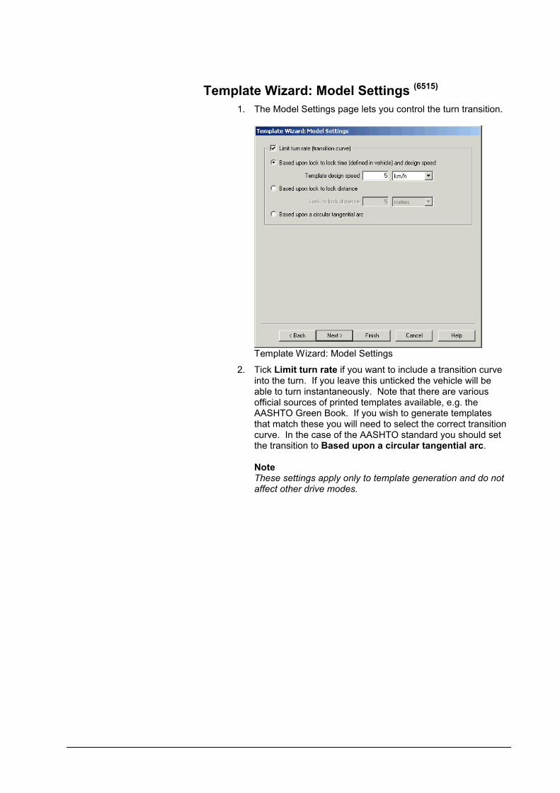
Template Wizard: Model Settings (6515)
1. The Model Settings page lets you control the turn transition.
Template Wizard: Model Settings
2. Tick Limit turn rate if you want to include a transition curve into the turn. If you leave this unticked the vehicle will be able to turn instantaneously. Note that there are various official sources of printed templates available, e.g. the AASHTO Green Book. If you wish to generate templates that match these you will need to select the correct transition curve. In the case of the AASHTO standard you should set the transition to Based upon a circular tangential arc.
NoteThese settings apply only to template generation and do not affect other drive modes.
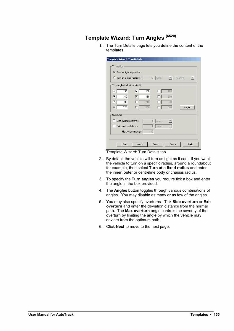
User Manual for AutoTrack Templates 155
Template Wizard: Turn Angles (6520)
1. The Turn Details page lets you define the content of the templates.
Template Wizard: Turn Details tab
2. By default the vehicle will turn as tight as it can. If you want the vehicle to turn on a specific radius, around a roundabout for example, then select Turn at a fixed radius and enter the inner, outer or centreline body or chassis radius.
3. To specify the Turn angles you require tick a box and enter the angle in the box provided.
4. The Angles button toggles through various combinations of angles. You may disable as many or as few of the angles.
5. You may also specify overturns. Tick Side overturn or Exit overturn and enter the deviation distance from the normal path. The Max overturn angle controls the severity of the overturn by limiting the angle by which the vehicle may deviate from the optimum path.
6. Click Next to move to the next page.

Template Wizard: Format (6530)
1. The Format page lets you specify the presentation of your template(s).
Template Wizard: Format tab
2. Select the Vehicle start orientation. Note that if you are inserting the template into a drawing you will be able to rotate it as it is inserted.
3. Select the Vehicle turn direction. If you are generating printed templates then this may be affected by which side of the road you drive on.
4. Tick Wheel track envelope to if kerbs are likely to be critical and / or Body envelope if walls or other high level obstacles are likely to be critical. Tick Offset body envelope to show an envelope with clearance margin. You can adjust the offset distance.
NoteYou must select at least one of these reports but you may select more than one.
5. Tick Add vehicle diagram to show a dimensioned image of the vehicle alongside the template. This is particularly useful on the printed templates.
6. If you are generating printed templates then you may wish to tick Place in a title block. This will add a title block with the vehicle name and other details.
7. Click Finish to generate the template.
8. If you are inserting a block then move it into position and confirm by left clicking. You may use the Rotate command to adjust the orientation.

User Manual for AutoTrack Swept Paths: Creating paths 157
Swept Paths: Creating paths
There are six drive modes in the full version of AutoTrack; AutoDrive Arc, AutoDrive Bearing, Manual Drive, Follow, Script and Vertical Clearance. Each may be accessed either directly from the toolbar or the drop down menu. A further drive mode allows you to insert parked vehicles.
AutoTrack Lite has Manual Drive, Follow and Script but does not have AutoDrive Arc, AutoDrive Bearing, Vertical Clearance or Dynamic Editing. It does however have the Park mode.
AutoTrack for Light Rail Design has only one drive mode, namely Guided Drive.

AutoDrive (Roads only)AutoDrive operates in two modes, Arc and Bearing. Both are controlled via a floating dialog which allows the user to adjust various parameters.
In Arc mode AutoTrack calculates a path, consisting of circular arcs, through target points specified by the user. In doing so it automatically generates any transitions necessary between segments.
In Bearing mode AutoTrack turns the vehicle as quickly as possible subject to the allowable lock rate until the steered wheels are on a bearing through the target point and then continues on that bearing until the selected path point reaches the target.
To use AutoDrive in Arc mode
AutoDrive Arc button
1. Select AutoDrive Arc from the AutoTrack drop down menu or click the AutoDrive Arc button on the AutoTrack toolbar.
2. If you have a default vehicle set up then AutoDrive will use this vehicle and you should go to step 6. If you want to use a different vehicle then right click now and refer to Changing your vehicle. Otherwise…
3. If you have a path pre-selected then AutoDrive will use the current vehicle and position and you should go to step 7. Otherwise…
4. The Library Explorer will appear for you to select a vehicle.
Library Explorer dialog
5. Select a vehicle and click Proceed. For help on how to select a vehicle refer to Selecting a vehicle to drive later in this section.
6. Your chosen vehicle will be displayed and can be positioned using the mouse. Position and orient your vehicle and click Proceed. For help on how to position a vehicle refer to Positioning a vehicle interactively later in this section.
User Manual for AutoTrack Swept Paths: Creating paths 159
NoteIf you have a simple body defined (i.e. of report type Body Outline (Plan)) AutoTrack will use this, otherwise it will use the detailed plan of type Body Detail (Plan).
7. Drive the vehicle (see below) and right click when finished.
To drive forwards on an arc
1. Move the cursor in front of the vehicle and pause. A ghosted image will show the path the vehicle will travel from the last position through the target point (the cursor).
2. If you cannot see a vehicle you may have your drawing units set incorrectly.
3. A straight red line connecting the cursor to the last position indicates that you are requesting a manoeuvre that cannot be performed and the error will be displayed in the bottom left corner of the AutoCAD status bar. Try moving the cursor to perform a less severe turn.
4. Move the cursor until the vehicle is in the desired position and left click to confirm. A vehicle outline will be drawn at the selected location and you may now repeat the process for the next position.
5. The AutoDrive options dialog allows you to specify aminimum radius and to change settings for the current turn. See below.
6. To turn tight and then travel straight tick Drive onto bearing.
To drive backwards on an arc
1. Move the cursor behind the vehicle and pause. A ghosted image will show the path the vehicle will travel from the last position through the target point (the cursor).
2. A straight red line connecting the cursor to the last position indicates that you are requesting a manoeuvre that cannot be performed and the error will be displayed in the bottom left corner of the AutoCAD status bar. Try moving the cursor to perform a less severe turn.
3. Move the cursor until the vehicle is in the desired position and left click to confirm. A vehicle outline will be drawn at the selected location and you may now repeat the process for the next position.
To use AutoDrive in Bearing mode
AutoDrive Bearing button
1. Select AutoDrive Bearing from the AutoTrack drop down menu or click the AutoDrive Bearing button on the AutoTrack toolbar. The default turn angle is 90 degrees. Note that on AutoCAD platforms only AutoDrive Bearing has a flyout toolbar listing standard turn angles of 30, 45, 60, 90, 120, 135, 150 and 180 degrees.

2. If you have a default vehicle set up then AutoDrive will use this vehicle and you should go to step 6. If you want to use a different vehicle then right click now and refer to Changing your vehicle.Otherwise…
3. If you have a path pre-selected then AutoDrive will use the current vehicle and position and you should go to step 7. Otherwise…
4. The Library Explorer will appear for you to select a vehicle.
Library Explorer dialog
5. Select a vehicle and click Proceed. For help on how to select a vehicle refer to Selecting a vehicle to drive later in this section.
6. Your chosen vehicle will be displayed and can be positioned using the mouse. Also displayed will be the AutoDrive Bearing options dialog. Position and orient your vehicle and click Proceed. For help on how to position a vehicle refer to Positioning a vehicle interactively later in this section.
7. Move the cursor in front of the vehicle and pause. A ghosted image will show the path the vehicle will travel from the last position through the target point (the cursor). Notice how the path is different from AutoDrive Arc.
8. Move the cursor until the vehicle is in the desired position and left click to confirm. A vehicle outline will be drawn at the selected location and you may now repeat the process for the next position.
9. You can delete the last selected position (target point) by simply left clicking with the cursor inside the wheelbase of the last drawn vehicle outline. This can be repeated back to the start of the path.
10. The AutoDrive options dialog allows you to specify turn angle and or radius and to change settings.
11. To drive arcs instead of straight segments untick Drive onto

User Manual for AutoTrack Swept Paths: Creating paths 161
bearing in the AutoDrive options dialog.
AutoDrive options (5110)
1. The AutoDrive dialog appears when you use either of the AutoDrive modes. It allows you not only to set turning criteria but also to switch between arc and bearing mode.
AutoDrive dialog (Arc mode)
2. To limit the turning radius tick Minimum radius, enter a value in the box and press <Tab> or <Enter>. You can select Inner Wheel or Outer Wheel to limit the inside or outside wheel tracking radius respectively, Inner Body or Outer Body to limit the inner or outer body envelope radius or Centreline to limit the radius at the centre of the streered axle.
Note Vehicle turning limitations still take precedence over the value in this field.
3. To show a clearance zone around the vehicle tick Clearance Offset. You may edit the offset value. The clearance envelope applies to both body and chassis, i.e. an offset envelope will be displayed outside the body static envelope and another outside the chassis static envelope. If you want to use a clearance envelope during driving then you should refer to Settings, AutoDrive.
4. To switch to bearing mode tick Turn onto bearing and to switch back untick it. When ticked the dialog expands to show extra fields.
AutoDrive dialog (Bearing mode)
5. Select Freehand turn (the default) to turn immediately and drive straight to the cursor. In this case the vehicle still turns as tightly as current constraints allow but there is never any straight section preceding the turn.
6. Select Picked alignment to specify the alignment by picking

a line or line segment from the drawing. You can align the vehicle parallel to the selected line or depress the Perpendicular To button to align the vehicle perpendicular to the selected line. Click the Pick alignment button to pick the alignment.
7. Select Turn through angle to turn as late as possible through a fixed angle. Select the angle from the drop down list or enter a value. The vehicle will turn as tightly as possible, subject to current constraints, through the specified angle and then drive straight to the cursor. As you move the cursor away from the last target point the sections preceding and following the turn adjust accordingly.
8. After the next target point has been picked following selection of a non-freehand bearing mode the bearing mode will switch automatically back to freehand mode.
9. Select Turn onto WCB (whole circle bearing) to turn as late as possible onto a fixed heading. Select the heading from the drop down list or enter a value. Again, the vehicle will turn as tightly as present constraints allow onto the specified heading and then straighten and drive to the cursor.
10. The current angle and bearing are displayed in the adjacent read-only boxes.
11. Select Side overturn to start the turn with opposite lock thereby reducing trailing axle cut-in. By adjusting the side overturn distance you can alter the size of the deviation.
12. Select Exit overturn to continue the turn beyond the required exit angle prior to turning back onto the required exit angle. As with side overturn this reduces trailing axle cut-in.
13. Adjust the Max overturn angle to alter the severity of the overturn. This is the maximum opposite lock bearing deviation. For example, if the vehicle commences a right turn from straight ahead on a bearing of 0 deg, a max overturn angle of 30 deg would allow the vehicle to turn left onto a maximum bearing of -30 before turning back. Note that the maximum overturn angle may not be reached when using smaller overturn distances.
14. If the vehicle has manually controllable secondary steering then to switch it on tick Override rear steering. Unick it to switch it off again. You can also do this by clicking the mouse wheel. When secondary steering is switched on the dialog expands to show more fields.
AutoDrive dialog (Secondary Steering)
15. The secondary steering may involve adjusting a linkage ratio or the wheel angle directly. Either way the slider shows the range of values. The current value is displayed in a box

User Manual for AutoTrack Swept Paths: Creating paths 163
Forwards and Reverse Predictive Turning buttons
labeled either Linkage Ratio or Wheel Angle depending according to the vehicle definition.
16. The easiest way to adjust the secondary steering value is to use the mouse wheel but you can move the slider if you prefer.
17. To check what other constraints are current tick Show Settings. When ticked the dialog expands to show the main settings.
AutoDrive dialog (Show Settings)
18. Depress the Forward Predictive Turning button to switch on the Predictive Turning envelope for forward manoeuvres or the Reverse Predictive Turning button for the same in reverse. You can change the settings for these in the AutoDrive settings. Note that for articulated vehicles the predictive turning envelopes are based upon a percentage (set in AutoDrive settings) of the tightest turn possible without the vehicle over-articulating. Thus it may be possible to turn tighter than the 100% envelope for a short distance.
19. Depress the Turn on spot button to disable any turn transitions for just the current step. The steering will turn instantaneously at the start of the step only. As soon as you click the next target position the option will be reset.
20. To limit the steering tick Limit steering to percentage or Limit steering to angle and edit the value if required. Note that limiting the steering by percentage is vehicle independent whereas limiting to a specific angle is not.
21. To limit the articulation angles tick Limit articulation to percentage or Limit articulation to angle and edit the value if required. Note that limiting the articulation angles by percentage is vehicle independent whereas limiting by angle is not.
22. To allow steering to be turned whilst the vehicle is stationary untick Limit forward turn rate or Limit reverse turn rate. When these limits are disabled (unticked) you should be able to see the steering pointer (if displayed) at the last picked position changing as you move the cursor to change the

current position.
23. If you are modeling higher speed manoeuvres (above about 15kph) then you may wish to tick Dynamic effects. This limits the turn radius to allow for passenger comfort. See Drawing Settings: Transitions (not Rail)
(2085)for more
details).
24. Tick Offset forwards TP (Tracking Point) or Offset reverse TP to offset the tracking point.
25. If you need to modify a value that is not listed click the Current Model button.

User Manual for AutoTrack Swept Paths: Creating paths 165
Manual Drive (not Rail)Manual Drive allows you to control the vehicle interactively much like the real vehicle, albeit with a different viewpoint and controls.
To use Manual Drive
Manual Drive button
1. Select Manual Drive from the AutoTrack drop down menu or click the Manual Drive button on the AutoTrack toolbar.
2. If you have a default vehicle set up then Manual Drive will use this vehicle and you should go to step 6. If you want to use a different vehicle then right click now and refer to Changing your vehicle. Otherwise…
3. If you have a path pre-selected then Manual Drive will use the current vehicle and position and you should go to step 7. Otherwise…
4. The Library Explorer will appear for you to select a vehicle.
Library Explorer dialog
5. Select a vehicle and click Proceed. For help on how to select a vehicle refer to Selecting a vehicle to drive later in this section.
6. Position and orient your vehicle and click Proceed. For help on how to position a vehicle refer to Positioning a vehicle interactively later in this section.
7. The Control Overlay will appear.

Manual Drive Control Overlay
8. By default the overlay will appear in the bottom right corner of the screen. If you find this awkward the location and size of the overlay can be changed in Manual Drive Settings.
To start driving (Control Overlay) (6020)
If you are using the default button functionality….
Go button
1. Click the Go button. The buttons will disappear and the cursor now represents requested steering angle and rate at which the path is generated (not design speed).
2. The vehicle will start to move when you move the cursor out of the stop zone. Notice how the caption bar changes from Driving: PAUSED to Driving: Forwards or Driving: Reverse to reflect the direction of travel. Click the left button again when you wish to pause.
3. Move the cursor between the two centre horizontal bands to stop moving, above the bands to go progressively faster forwards and below the bands to go progressively faster in reverse.
4. Move the cursor left to turn the steered wheels left and vice versa. Practice reversing and driving rear steered vehicles until you feel comfortable with the steering response.
5. A dotted line representing the current wheel angle is displayed on the overlay. If you have steering rate limits enabled you may notice that it lags behind the requested steering angle represented by the cursor. The degree to which it lags behind depends upon the steering rate criteria. The actual wheel angle line will snap the centre of the full lock and straight ahead zones.
6. Click anywhere on the overlay to pause the vehicle and redisplay the buttons.

User Manual for AutoTrack Swept Paths: Creating paths 167
If you have specified hold down button to drive…
1. Move the cursor into the zone above or below the buttons and hold down the left mouse button. The buttons will disappear and the cursor now represents requested steering angle and rate at which the path is generated (not design speed).
41. As long as you hold the button down the overlay buttons will not be visible and the vehicle will start to move as you move the cursor out of the stop zone. Notice how the caption bar changes from Driving: PAUSED to Driving: Forwards or Driving: Reverse to reflect the direction of travel. As soon as you release the left mouse button the vehicle will stop moving and the overlay buttons will reappear.
42. Move the cursor between the two centre horizontal bands to stop moving, above the bands to go progressively faster forwards and below the bands to go progressively faster in reverse.
43. Move the cursor left to turn the steered wheels left and vice versa. Practice reversing and driving rear steered vehicles until you feel comfortable with the steering response.
44. A dotted line representing the current wheel angle is displayed on the overlay. If you have steering rate limits enabled you may notice that it lags behind the requested steering angle represented by the cursor. The degree to which it lags behind depends upon the steering rate criteria. The actual wheel angle line will snap the centre of the full lock and straight ahead zones.
45. Release the mouse button to pause the vehicle and redisplay the buttons.
NoteIf you have configured your mouse for left-handed use or selected left hand drive in the Manual Drive settings then you will need to hold down the right mouse button to drive.
To pause driving
If you are using the default button functionality….
1. Right click. The overlay buttons will appear.
If you have specified hold down button to drive…
1. Release the left mouse button. The overlay buttons will appear.
NoteIf you have swapped the mouse button functionality, either in the Windows Control Panel or in the Manual Drive settings then you will need to click (or release) the right mouse button.
To adjust the view
1. For your convenience the View toolbar functions are repeated on this dialog. For help in adjusting the view refer to Adjusting the view.
To undo part of the path
Auto Undo button
1. If the overlay buttons are not displayed pause driving to display them.
2. Click the Auto Undo button.
3. The path will be shortened by the Auto Undo distance. The Auto Undo distance is 2.5m by default but can be modified if a different value is more appropriate. For details of how to modify the Auto Undo distance refer to System Settings: Manual Drive (not Rail).
To redraw the path and update the reports
1. If the overlay buttons are not displayed pause driving to display them.
2. Click the Redraw button.
3. The path and all reports will be redrawn.
To show or hide the vehicle trail
Show Trails button
1. If the overlay buttons are not displayed pause driving to display them.
2. Click the Show Trails button to toggle displaying and hiding vehicle trails as you drive. If the button is depressed trails will be displayed.
To edit the path properties
Properties button
1. If the overlay buttons are not displayed pause driving to display them.
2. Click the Properties button.
3. The Path Properties dialog will appear. Edit the properties and click OK to confirm and resume driving.
To edit the path reports
Reports button
1. If the overlay buttons are not displayed pause driving to display them.
2. Click the Reports button.
3. The path properties dialog will appear with the Reports tab foremost. Edit the reports and click OK to confirm and resume driving.
To terminate the current path
Stop button
1. If the overlay buttons are not displayed pause driving to display them.
2. Click the Stop button.
3. The control overlay will disappear.
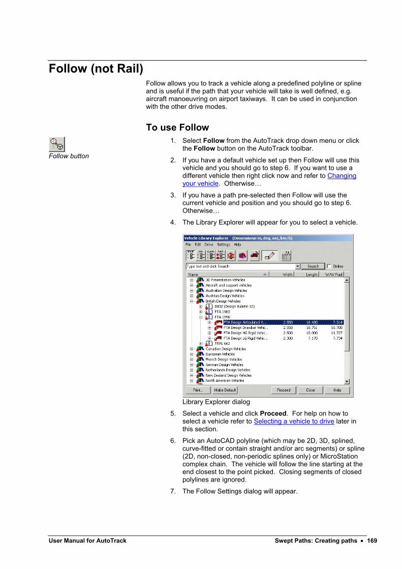
User Manual for AutoTrack Swept Paths: Creating paths 169
Follow (not Rail)Follow allows you to track a vehicle along a predefined polyline or spline and is useful if the path that your vehicle will take is well defined, e.g. aircraft manoeuvring on airport taxiways. It can be used in conjunction with the other drive modes.
To use Follow
Follow button
1. Select Follow from the AutoTrack drop down menu or click the Follow button on the AutoTrack toolbar.
2. If you have a default vehicle set up then Follow will use this vehicle and you should go to step 6. If you want to use a different vehicle then right click now and refer to Changing your vehicle. Otherwise…
3. If you have a path pre-selected then Follow will use the current vehicle and position and you should go to step 6. Otherwise…
4. The Library Explorer will appear for you to select a vehicle.
Library Explorer dialog
5. Select a vehicle and click Proceed. For help on how to select a vehicle refer to Selecting a vehicle to drive later in this section.
6. Pick an AutoCAD polyline (which may be 2D, 3D, splined, curve-fitted or contain straight and/or arc segments) or spline (2D, non-closed, non-periodic splines only) or MicroStation complex chain. The vehicle will follow the line starting at the end closest to the point picked. Closing segments of closed polylines are ignored.
7. The Follow Settings dialog will appear.

Follow Drive Settings dialog
8. Make sure that the Start Direction is set to the correct direction. Select Forwards or Reverse to force the direction of travel. Select Keep Current to continue in the current direction (if this manoeuvre follows one performed using a different drive mode). Select Automatic to determine the direction of travel based upon the orientation of the vehicle relative to the starting vertex of the polyline.
9. If you have a path pre-selected then the current vehicle position and orientation will be used and you should go to step 10. Otherwise, you will probably want Start Position set to Automatic, which will start the vehicle at the end of the line closest to the point you picked, with the steered wheels tangential to the line and all the spines aligned. If you want to adjust the position of the vehicle then select Manual.
10. If you are modelling aircraft then you should click on the Tracking Point tab and check that the Tracking Point’s are set correctly, i.e. typically, Pilot’s Eye or Front most Axle.
11. Change any other settings if necessary (see System Settings: Follow Drive (not Rail)) and then click OK.
12. The swept path will be generated and the path redrawn.

User Manual for AutoTrack Swept Paths: Creating paths 171
Script (not Rail)The Script language allows you to specify paths as a series of very well defined and manoeuvres. This means that you can generate “templates” of commonly used manoeuvres. It works with or without a pre-selected vehicle or path.
To create or edit an AutoTrack script (6050)
Script button
1. Select Script from the AutoTrack drop down menu or click the Script button on the AutoTrack toolbar.
2. The Script Editor will appear. If you have already edited a script then this will appear in Command Script window.
Script Editor
3. Type your manoeuvre commands in the edit box. Each line that you type will be added to the Command Script window.
4. To remove a line, highlight it in the Command Script window and click Remove. The line will be removed.
TipYou can select multiple lines for deletion by dragging and/or using Ctrl-Click.
5. To insert a command, highlight the position in the Command Script window and click Insert. A blank line will be inserted.
6. To copy a line to the end of the script, highlight it in the Command Script box and click Copy.
TipSelect multiple lines for copying by dragging and/or using Ctrl-Click.
7. To clear the current command script click New.
8. You may print a hardcopy of a script by clicking the Printbutton.
9. A full list of script commands appears at the end of this section.
To run an AutoTrack script
1. Create or load the required script.
2. Make sure that you have no path selected and then click the Run Script button.
3. The manoeuvre(s) will be generated on layers defined by the current layering convention settings. However, unlike other drive modes the script command will not prompt for a layer name if this option is enabled.
4. If the manoeuvre is incomplete then check the command line, it was probably impossible.
To save an AutoTrack script
1. Click the Save button. The Save As dialog will appear.
2. Browse to the directory in which you wish to save the script and then click Save.
To load an AutoTrack script
1. Click the Load button.
2. Browse to find the file that you wish to load and then click Load.
AutoTrack script commands
There follows a list of script commands for reference purposes.
Script Commands: General
;textComment line (ignored)
EtextEcho text to the command line when the script is run
UtextSet the distance units for the rest of the script to text, where text is a valid units abbreviation (e.g. ‘ft’, ‘m’. ‘mm’ etc.). The default units are metres.
Script Commands: New Path
AutoTrack will automatically prompt for a vehicle, i.e. issue a V?command, if none is given in the script. A V? command in a script is ignored if a vehicle or path has been pre-selected.
NStart a new path, using the currently selected vehicle (the start settings of the new path match the old path)
V?Select the vehicle interactively (prompts for a vehicle using the Library Explorer)

User Manual for AutoTrack Swept Paths: Creating paths 173
Script Commands: Positional
The following positional commands are ignored if a drive command has been issued or if a path has been pre-selected. AutoTrack will automatically prompt for position, i.e. issue a P?command, if none is given in the script.
P?Set the position interactively(if this command is placed at the end of the script you will be able to position the scripted manoeuvre)
Px,y
Set the start position of the path to x,y in the current UCS
H?Set the heading interactively
HbSet the heading to b degrees in the current UCS
S?Set the wheel angle interactively
SaS+aSet the steering right at angle a
Sra
Set the steering right at angle a
S–aSet the steering left at angle a
Sla
Set the steering left at angle a
A?Set the articulation angles of all units interactively (prompts for unit and then angle)
An?Set the articulation angle of unit n interactively (prompts for just the angle)
An a
Set the articulation angle of unit n a degrees to the right
An +aSet the articulation angle of unit n a degrees to the right
AnRa
Set the articulation angle of unit n a degrees to the right
An –aSet the articulation angle of unit n a degrees to the left
AnLa
Set the articulation angle of unit n a degrees to the left

Script Commands: Drive
Drive commands take the general form:-
{Direction}{Manoeuvre}[Turn condition]{Stop condition}
In the following list {S} indicates a mandatory stop condition and [T] indicates an optional turn condition.
F{S}Drive forwards at current steering angle
R{S}Reverse at current steering angle
FC{S}Drive forwards at current steering angle
RC{S}Reverse at current steering angle
FH{S}Drive forwards with hands off(i.e. maintaining current wheel heading)
FL[T]{S}Drive forwards and turn left as tightly as possible
RL[T]{S}Reverse and turn left as tightly as possible
FR[T]{S}Drive forwards and turn right as tightly as possible
RR[T]{S}Reverse and turn right as tightly as possible
Script Commands: Stop Conditions {S}
A vehicle will automatically stop if it encounters an error state, for example if it over-articulates.
AStop when the wheel angle has increased by angle a(in the direction of the turn)N.B. applies only to turn commands, e.g. FL, FR, etc
BaStop when the wheel bearing has reached a
WaStop when the wheel angle has increased by angle a(in the direction of the turn)
WbaStop when wheel bearing reaches a in the current UCS
d
Stop after distance dN.B. applies only to non-turn commands, e.g. F, R, etc
DdStop after distance d
Ta
Stop when tractor spine angle has increased by angle a
Tba
User Manual for AutoTrack Swept Paths: Creating paths 175
Stop when tractor spine reaches bearing a in the current UCS
Un a
Stop when the spine angle of unit n has increased by angle a
UnBaStop when the spine angle of unit n reaches bearing a in the current UCS
AaStop when any articulation angle exceeds angle a
An aStop when the articulation angle of unit n exceeds angle a
An1:n2 aStop when the articulation angle between units n1 and n2
reaches angle a
Script Commands: Turn Conditions [T]
CrSet the steering to achieve a centre line chassis radius r
OrSet the steering to achieve an outer wheel radius r
Ir Set the steering to achieve an inner wheel radius r
ObrSet the steering to achieve an outer body radius r
IbrSet the steering to achieve an inner body radius radius r
SaS+a
Set the steering right at angle a
S-aSet the steering left at angle a

Guided Drive (Rail only)The Guided Drive mode is used for trams and other light rail vehicles in which the vehicles position is entirely dictated by the rail layout.
To use Guided Drive
Guided Drive button
1. Select Guided Drive from the AutoTrack drop down menu or click the Guided Drive button on the AutoTrack toolbar.
2. If you have a default vehicle set up then AutoTrack will use this vehicle and you should go to step 6. If you want to use a different vehicle then right click now and refer to Changing your vehicle. Otherwise…
3. If you have a path pre-selected then AutoTrack will use the current vehicle and position and you should go to step 7. Otherwise…
4. The Library Explorer will appear for you to select a vehicle.
Library Explorer dialog
5. Select a vehicle and click Proceed. For help on how to select a vehicle refer to Selecting a vehicle to drive later in this section.
6. Pick an AutoCAD polyline (which may be 2D, 3D, splined, curve-fitted or contain straight and/or arc segments) or MicroStation complex chain. The vehicle will follow the line starting at the end closest to the point picked. Closing segments of closed polylines are ignored.
7. The Guided Drive Settings dialog will appear.

User Manual for AutoTrack Swept Paths: Creating paths 177
Guided Drive Settings dialog
8. Make sure that, if you want the vehicle to reverse along the line, the Direction is set to Reverse and then click OK.
9. The swept path will be generated and the path redrawn.
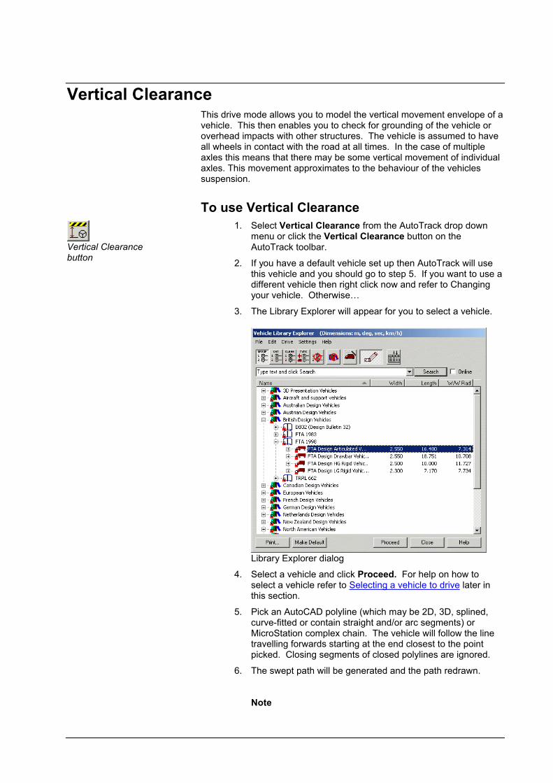
Vertical ClearanceThis drive mode allows you to model the vertical movement envelope of a vehicle. This then enables you to check for grounding of the vehicle or overhead impacts with other structures. The vehicle is assumed to have all wheels in contact with the road at all times. In the case of multiple axles this means that there may be some vertical movement of individual axles. This movement approximates to the behaviour of the vehicles suspension.
To use Vertical Clearance
Vertical Clearance button
1. Select Vertical Clearance from the AutoTrack drop down menu or click the Vertical Clearance button on the AutoTrack toolbar.
2. If you have a default vehicle set up then AutoTrack will use this vehicle and you should go to step 5. If you want to use a different vehicle then right click now and refer to Changing your vehicle. Otherwise…
3. The Library Explorer will appear for you to select a vehicle.
Library Explorer dialog
4. Select a vehicle and click Proceed. For help on how to select a vehicle refer to Selecting a vehicle to drive later in this section.
5. Pick an AutoCAD polyline (which may be 2D, 3D, splined, curve-fitted or contain straight and/or arc segments) or MicroStation complex chain. The vehicle will follow the line travelling forwards starting at the end closest to the point picked. Closing segments of closed polylines are ignored.
6. The swept path will be generated and the path redrawn.
Note

User Manual for AutoTrack Swept Paths: Creating paths 179
It is assumed that all wheels will remain in contact with the road. In order to do this some wheels will rise and some will fall. The extent of this movement is not controllable by theuser.
WarningVertical Clearance mode uses default values for ground clearance and overall height that are unlikely to match your requirements. In order to generate useful results you MUSTobtain and enter the accurate height and ground clearance.
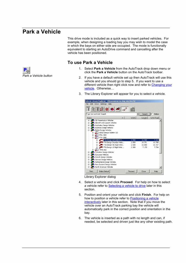
Park a VehicleThis drive mode is included as a quick way to insert parked vehicles. For example, when designing a loading bay you may wish to model the case in which the bays on either side are occupied. The mode is functionally equivalent to starting an AutoDrive command and cancelling after the vehicle has been positioned.
To use Park a Vehicle
Park a Vehicle button
1. Select Park a Vehicle from the AutoTrack drop down menu or click the Park a Vehicle button on the AutoTrack toolbar.
2. If you have a default vehicle set up then AutoTrack will use this vehicle and you should go to step 5. If you want to use a different vehicle then right click now and refer to Changing your vehicle. Otherwise…
3. The Library Explorer will appear for you to select a vehicle.
Library Explorer dialog
4. Select a vehicle and click Proceed. For help on how to select a vehicle refer to Selecting a vehicle to drive later in this section.
5. Position and orient your vehicle and click Finish. For help on how to position a vehicle refer to Positioning a vehicle interactively later in this section. Note that if you move thevehicle over an AutoTrack parking bay the vehicle will automatically park in the correct position and orientation in the bay.
6. The vehicle is inserted as a path with no length and can, if needed, be selected and driven just like any other existing path.

User Manual for AutoTrack Swept Paths: Creating paths 181
Selecting a vehicle to driveFor details of the vehicles see Vehicle Libraries.
Vehicle Library button
Insert / Remove Columns button
Vehicle Diagram button
1. If you don’t have a default vehicle selected or you wish to use a different vehicle select Vehicle Library from the AutoTrack drop down menu or click the Vehicle Librarybutton on the AutoTrack toolbar. The Library Explorer will appear.
Library Explorer dialog
2. If you do not have a vehicle library loaded all you will see is a bookshelf icon with the text Pool beside it. This represents the pool of vehicles used in and saved with your drawing.
3. If you have already used a vehicle then there will be a small + symbol beside the Pool icon. Click on this and the Pool will expand to list the vehicles held in the drawing.
4. The buttons at the top are mutually exclusive and allow you to group the vehicles by Vehicle Group (default), Category, Classification, Type or Ungrouped. There is also an option to display all vehicles for all libraries together.
5. The arrow on the header bar allows you to list the data in ascending or descending alphanumeric order. Click on the arrow to change the order or click on another column header to sort by another item of data.
6. You can add or remove data from the display by clicking the Insert/Remove Columns button. See Customising the Library Explorer view (Library Explorer Columns dialog)
(3515)
7. Click the Vehicle Diagram button to switch the vehicle diagram on and off. See Vehicle Diagram dialog for details.
8. For more details of the Library Explorer dialog see Viewing a vehicle in a library or the pool (Library Explorer dialog) (3510) in Viewing and editing vehicles).

To open a vehicle library
Vehicle Library icon1. To open a library, select Open Library from the File menu
on the Library Explorer or right click and select Open Libraryfrom the menu that appears.
2. Browse to the Library subdirectory of the AutoTrack directory, select a library and click Open.
3. A new Vehicle Library icon will appear in the Library Explorer with the name of the library beside it.
4. Click on the + symbol to expand the library.
To select a vehicle from a loaded library
Vehicle Library icon1. Vehicle libraries are indicated by a bookshelf icon.
2. Click on the + symbol beside the library (or pool) that contains the required vehicle. The library will expand to reveal a list of vehicle groups.
3. Expand the category by clicking on the + symbol. A list of vehicles will appear.
4. Highlight a vehicle and click Proceed to select it.
5. If you do not have a default vehicle set then you will be asked if you want to make this your default vehicle. See Default Vehicle dialog.
6. If your scale appears to be incorrect you will be given the opportunity to change it. See Scale dialog.
7. The vehicle has been selected and may now be positioned. Proceed to Positioning a vehicle interactively.
NoteIf you have the prompt for scale option enabled you will see the Drawing Settings dialog before the Position Vehicle dialog.
To close a vehicle library
1. Highlight the library that you want to close.
46. Select Close Library from the File menu on the Library Explorer or right click and select Close Library from the menu that appears.
47. The selected library will be removed from the Library Explorer.
To set a default vehicle
1. Highlight the vehicle that you want to set as your default and click the Make Default button.
48. The next time you select a drive mode this vehicle will be used.

User Manual for AutoTrack Swept Paths: Creating paths 183
Default Vehicle dialog (5100)
1. AutoTrack allows you to define a default vehicle, i.e. a vehicle that will be used every time you start to drive unless you actively select an alternative. This can be very useful if you regularly use the same vehicle. If you select a vehicle to drive and you do not have a default vehicle set the Default Vehicle dialog will appear.
Default Vehicle dialog
2. If you select Yes then this vehicle will be selected automatically next time you use any drive command. If you select No then you will be asked this again the next time you select a vehicle in similar circumstances.
3. If you don’t want to be asked again then tick Don’t ask me this again.
Scale dialog (5130)
1. If you are using the wrong units, e.g. AutoTrack is set to use millimeters but your drawing is in metres, your vehicle will appear out of proportion with the background. If this occurs and you have automatic scale checking enabled the Scale dialog will appear.
Scale dialog
49. Check your units are correct and change them if necessary.
50. If you want to switch off automatic scale checking then tick Don’t ask me this again.

Changing your vehicleYou can change your vehicle selection at any time before you start driving.
To change the selected vehicle
Vehicle Library button
1. Right click to display the Position Vehicle dialog.
Position Vehicle dialog
2. Click the Vehicle Library button.
3. Select the new vehicle. For help on how to select a vehicle refer to Selecting a vehicle to drive in this section.
4. Click Proceed to position the vehicle interactively.

User Manual for AutoTrack Swept Paths: Creating paths 185
Positioning a vehicle interactivelyThe vehicle orientation can be adjusted interactively until you start to drive. Once you have started to drive you may adjust the initial orientation using the Path tools.
With the vehicle selected move the cursor along the spine of the vehicle. Notice the small square that appears at each coupling point and at the front axle of the first unit. This is called a grip and is used to change between adjusting position, heading and articulation.
To change the position of the vehicle
1. Move the cursor until the positioning grip appears over the front axle of the first unit and left click.
51. Use the mouse to move vehicle to the required location and left click to confirm.
To change the heading of the vehicle
1. Move the cursor until the positioning grip appears at the rear coupling of the first unit and left click.
2. Use the mouse to adjust the heading of the entire vehicle and left click to confirm.
To adjust the articulation
1. Move the cursor until the positioning grip is at the coupling point whose angle you want to adjust and left click.
2. Use the mouse to adjust the articulation angle and left click to confirm.

Positioning a vehicle (Position Vehicle dialog) (6000)
If you don’t want to use the interactive vehicle positioning right click immediately after selecting your vehicle and the Position Vehicle dialog will appear.
Position Vehicle dialog
To set or change the position of the vehicle
Location button
1. Click the Location button.
2. Use the mouse to move the vehicle and click the mouse button to confirm.
To set or change the heading of the entire vehicle
Heading button
1. Click the Heading button.
2. Use the mouse to adjust the orientation and click the mouse button to confirm.
To set or change the starting steering angle
Steering button
1. Click the Steering button.
2. Use the mouse to adjust the steering angle and click the mouse button to confirm.
To set or change the starting orientation of a selected spine
Articulation button
1. Click the Articulation button.
2. If there is only one articulation point then you will automatically be requested to adjust the trailer spine. If there is more than one articulation point you will be asked to pick the unit that you want to adjust. In either case simply move the cursor to reorient the appropriate spine and click the mouse button to confirm.

User Manual for AutoTrack Swept Paths: Creating paths 187
To position the vehicle at the start of an existing path
Start of Path button
1. Click the Start of Path button.
2. You will be asked to select the path.
To position the vehicle at the end of an existing path
End of Path button
1. Click the End of Path button.
2. You will be asked to select the path.
To position the vehicle at a point on an existing path
Point on Path button
1. Click the Point on Path button.
2. You will be asked to point to the required position.
To view the path properties
Properties button
1. Click the Properties button.
To view the model settings
Model button
1. Click the Model button.
To undo the last operation
Undo button
1. Click the Undo button.
To start driving
Proceed button
1. Click the Proceed button.
2. The Drive dialog (or the Drive command line) will appear.
To adjust the view
For your convenience the View toolbar functions are repeated on this dialog. For help in adjusting the view refer to Adjusting the view.
Adjusting the view (View toolbar)Whilst you can use the built-in CAD functions to manipulate the view, AutoTrack includes a number of intelligent view functions that take account of the current AutoTrack path.
To reset any drawing rotation
Reset Rotation button
1. Select Rotate, Reset from the AutoTrack, View drop down menu or click the Reset Rotation button.
2. The drawing rotation will be reset to zero.
To rotate the drawing to the left
Rotate Left button
1. Select Rotate, Left from the AutoTrack, View drop down menu or click the Rotate Left button.
2. The drawing will be rotated 45 degrees to the left.
To rotate the drawing to the right
Rotate Right button
1. Select Rotate, Right from the AutoTrack, View drop down menu or click the Rotate Right button.
2. The drawing will be rotated 45 degrees to the right.
To rotate the drawing automatically
AutoRotate button
1. Select Rotate, Auto from the AutoTrack, View drop down menu or click the AutoRotate button.
2. The drawing will be rotated until the steered wheels point directly up the screen.
To pan the image (e.g. if the vehicle is close to the edge of the window)
AutoPan button
1. Select AutoPan from the AutoTrack, View drop down menu or click the AutoPan button.
2. By default this will move the drawing so that after the pan the steered wheels of the vehicle are located slightly off centre and pointing directly through the centre of the screen. Depending upon your settings the drawing may also be rotated.
To zoom in
Zoom In button
1. Select Zoom, In from the AutoTrack, View drop down menu or click the Zoom In button.
2. The screen image will be magnified by a factor of 2.
To zoom out
1. Select Zoom, Out from the AutoTrack, View drop down menu or click the Zoom Out button.
User Manual for AutoTrack Swept Paths: Creating paths 189
Zoom Out button2. The screen image will be reduced by a factor 0.5.
To show only the vehicle body
Show Body button
1. Select Show Body from the AutoTrack, View drop down menu or click the Show Body button.
2. Only the body of each unit to will be displayed whilst driving.
To show only the vehicle chassis
Show Chassis button
1. Select Show Chassis from the AutoTrack, View drop down menu or click the Show Chassis button.
2. Only the chassis of each unit will be displayed whilst driving.
To show both the vehicle body and chassis
Show All button
1. Select Show All from the AutoTrack, View drop down menu or click the Show All button.
2. Both the body and the chassis of all units will be displayed whilst driving.


User Manual for AutoTrack Swept Paths: Editing paths 191
Swept Paths: Editing paths
All swept paths, as long as they have not been exploded can be edited to adjust the colour, content or even alignment. The AutoTrack Properties command lets you edit a single path whilst the Drawing Explorer allows you to copy path attributes between drawings.
Adjusting the path alignment (Path toolbar)TipAlmost all the operations described in this section are simpler to perform using grip editing. See Adjusting the path alignment using grip editing.
All paths, except those created using Guided Drive, are stored as a series of target points through which the vehicle is required to drive. AutoTrack allows you to move the target points of a path, dynamically updating the path to reflect changes in position.
If you edit the path in such a way that the vehicle cannot get from a given point to the next target the remainder of the path will drawn as a single line (red by default). See Undriveable Paths
(5050).
Edit Path button
1. Click the Edit Path button on the toolbar. The Path toolbar will appear.
Path toolbar
To see the target points on the path
Target points are shown as small diagonal crosses along the path. If you cannot see any target points on your path make sure that you have them enabled. To do this…
Properties button
1. Select Properties from the AutoTrack drop down menu or click the Properties button on the main AutoTrack toolbar and select the path if necessary. The Path Properties dialog will appear.
2. Select the Reports tab.
3. Expand the Construction Lines report by clicking on the small + symbol and make sure that both the Construction Lines report and the Target Points sub-report are ticked.
To see the steering pointer
The steering pointer is a line drawn from the centre of the primary steered axle at the same angle as the steered wheels. If you cannot see the steering pointer then make sure you have it enabled. To do this…
Properties button
1. Select Properties from the AutoTrack drop down menu or click the Properties button on the main AutoTrack toolbar and select the path if necessary. The Path Properties dialog will appear.
2. Select the Reports tab.
3. Expand the Construction Lines report by clicking on the small + symbol and make sure that both the Construction Lines report and the Steering Pointer sub-report are ticked.
To adjust the vehicle start position (not Rail)
Location button
1. Select Initial Location from the AutoTrack, Path drop down menu or click the Location button on the Path toolbar.
2. Select the path if necessary.
3. Move the mouse until the vehicle is in the required location and left click to confirm.
To adjust the vehicle start heading (not Rail)
Heading button
1. Select Initial Heading from the AutoTrack, Path drop down menu or click the Heading button on the Path toolbar.
2. Select the path if necessary.
3. Move the mouse until the vehicle is in the required orientation and left click to confirm.
To adjust the vehicle start steering angle (not Rail)
Steering button
1. Select Initial Steering Angle from the AutoTrack, Path drop down menu or click the Steering button on the Path toolbar.
2. Select the path if necessary.
3. Move the mouse until the steering is at the required angle and left click to confirm.
To adjust the vehicle start spine angles (not Rail)
Articulation button
1. Select Initial Articulation Angle from the AutoTrack, Path drop down menu or click the Articulation button on the Path toolbar.
2. Select the path if necessary.
3. Select the required unit and move the mouse until it is in the required orientation and then left click to confirm.
To move the path
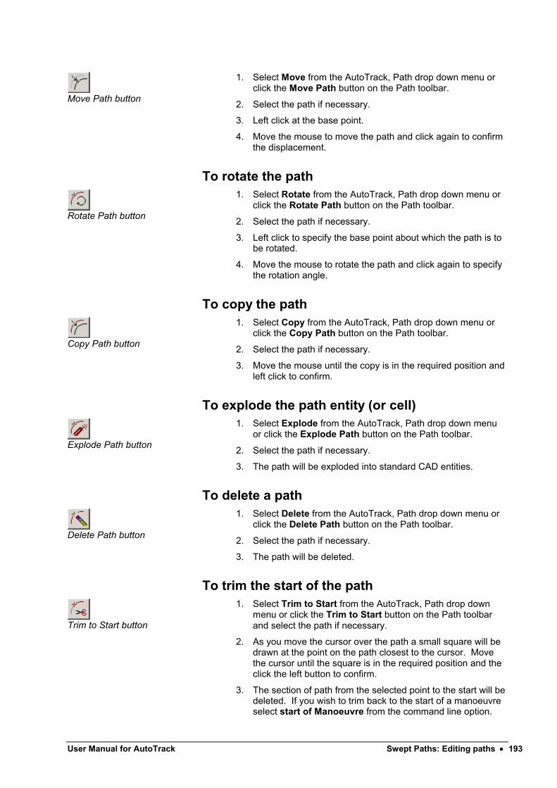
User Manual for AutoTrack Swept Paths: Editing paths 193
Move Path button
1. Select Move from the AutoTrack, Path drop down menu or click the Move Path button on the Path toolbar.
2. Select the path if necessary.
3. Left click at the base point.
4. Move the mouse to move the path and click again to confirm the displacement.
To rotate the path
Rotate Path button
1. Select Rotate from the AutoTrack, Path drop down menu or click the Rotate Path button on the Path toolbar.
2. Select the path if necessary.
3. Left click to specify the base point about which the path is to be rotated.
4. Move the mouse to rotate the path and click again to specify the rotation angle.
To copy the path
Copy Path button
1. Select Copy from the AutoTrack, Path drop down menu or click the Copy Path button on the Path toolbar.
2. Select the path if necessary.
3. Move the mouse until the copy is in the required position and left click to confirm.
To explode the path entity (or cell)
Explode Path button
1. Select Explode from the AutoTrack, Path drop down menu or click the Explode Path button on the Path toolbar.
2. Select the path if necessary.
3. The path will be exploded into standard CAD entities.
To delete a path
Delete Path button
1. Select Delete from the AutoTrack, Path drop down menu or click the Delete Path button on the Path toolbar.
2. Select the path if necessary.
3. The path will be deleted.
To trim the start of the path
Trim to Start button
1. Select Trim to Start from the AutoTrack, Path drop down menu or click the Trim to Start button on the Path toolbar and select the path if necessary.
2. As you move the cursor over the path a small square will be drawn at the point on the path closest to the cursor. Move the cursor until the square is in the required position and the click the left button to confirm.
3. The section of path from the selected point to the start will be deleted. If you wish to trim back to the start of a manoeuvre select start of Manoeuvre from the command line option.

The vehicle will only be drawn at the start of each manoeuvre (i.e. at each target point). Again click the left button to confirm.
To trim the end of the path
Trim to End button
1. Select Trim to End from the AutoTrack, Path drop down menu or click the Trim to End button on the Path toolbar and select the path if necessary.
2. As you move the cursor over the path a small square will be drawn at the point on the path closest to the cursor. Move the cursor until the square is in the required position and the click the left button to confirm.
3. The section of path from the selected point to the end will be deleted. If you wish to trim back to the start of a manoeuvre select start of Manoeuvre from the command line option. The vehicle will only be drawn at the start of each manoeuvre (i.e. at each target point). Again click the left button to confirm.
To move target points (not Rail)
Edit Path button
1. Select Edit Path from the AutoTrack, Path drop down menu or click the Edit Path button on the Path toolbar and select the path if necessary.
2. A small square will appear on the path and move as you move the mouse. This square represents the point to be moved.
3. Move the mouse until the square is at the target point that you wish to move (it snaps and changes colour when you get close to one) and left click to select it.
4. Now move the mouse until the selected point is in the required new location and left click to confirm.
To insert a new target point (not Rail)
Normally it is preferable to use the fewest possible target points as this will produce the smoothest path. However, there will be cases where you need to insert a new target point.
Edit Path button
1. Select Edit Path from the AutoTrack, Path drop down menu or click the Edit Path button on the Path toolbar and select the path if necessary.
2. A small square will appear on the path and move as you move the mouse. This square represents the point to beedited or the point at which a new target would be inserted.
3. Move the mouse until the square is at the position at which you want to insert the new target (may not be a target point already) and left click to confirm. A new target point will appear (indicated by a diagonal cross) and can be moved in the normal way.

User Manual for AutoTrack Swept Paths: Editing paths 195
To remove intermediate target points (not Rail)
Edit Path button
1. Select Edit Path from the AutoTrack, Path drop down menu or click the Edit Path button on the Path toolbar and select the path if necessary.
2. A small square will appear on the path and move as you move the mouse. This square represents the point to be edited.
3. Move the mouse until the square is at the point that you want to delete (it snaps and changes colour when you get close to one) and left click to confirm.
4. Now move the mouse to the preceding or following target point (denoted by diagonal crosses) and click the left button again. The selected target point will be removed.
To delete the last target point (not Rail)
Delete Last Target button
1. Select Delete Last Target from the AutoTrack, Path drop down menu or click the Delete Last Target button on the Path toolbar and select the path if necessary.
2. The last target point on the selected path will be removed.
TipYou can delete the last target point “on-the-fly” whilst using AutoDrive. Left click with the cursor inside the wheelbase of the last drawn vehicle position.
Adjusting the path alignment using grip editingAll paths, except those created using Guided Drive, are stored as a series of target points through which the vehicle is required to drive. The Dynamic Edit functionality incorporated in AutoTrack allows you to move the target points of a path, dynamically updating the path to reflect changes in position. Grip editing mode allows you to make all path adjustments interactively simply by picking and dragging grips.
If you edit the path in such a way that the vehicle cannot get from a given point to the next target the remainder of the path will drawn as a single line (red by default). See Undriveable Paths
(5050).
NoteAutoDrive and Dynamic Editing are options and may not be available on your copy.
To enter grip editing mode
1. Select the path and click Edit Path on the Path Edit toolbar or select Path Edit, Edit Path from the AutoTrack drop down menu.
2. Grips will appear at various locations along the path and vehicle. The shape of the grips indicates what they do and when you hover over the grip it will change colour and a text grip tip will confirm the associated action.
NoteAutoCAD and SavoyCAD have their own grip editing modes

which are enabled by simply selecting the path. This works just like the AutoTrack’s dynamic editing mode.
To see the target points on a path
Target points are shown as small diagonal crosses along the path. If you cannot see any target points on your path make sure that you have target point markers enabled in the Construction Lines settings. To do this…
Properties button
1. Select Properties from the AutoTrack drop down menu or click the Properties button on the main AutoTrack toolbar and select the path if necessary. The Path Properties dialog will appear.
2. Select the Reports tab.
3. Expand the Construction Lines report, by clicking on the + symbol, and make sure that both Construction Lines and Target Points are ticked.
To see the steering pointer
The steering pointer is a line drawn from the centre of the primary steered axle at the same angle as the steered wheels. If you cannot see the steering pointer then make sure you have the steering pointer enabled in the Construction Lines settings. To do this…
Properties button
1. Select Properties from the AutoTrack drop down menu or click the Properties button on the main AutoTrack toolbar and select the path if necessary. The Path Properties dialog will appear.
2. Seelct the Reports tab.
3. Select the Construction Lines tab followed by the Steering Pointer tab and make sure that both Construction Linesand Steering Pointer are ticked.
To adjust the vehicle start heading (not Rail)
1. Enter grip editing mode so that the editing grips appear. (See To enter grip editing mode).
2. Select the Adjust Spine Angle grip on the first unit.
3. Move the mouse to rotate the units and right click again to confirm the new position.
To adjust the vehicle start steering angle (not Rail)
1. Enter grip editing mode so that the editing grips appear. (See To enter grip editing mode).
2. Select the Adjust Steering Angle grip at the end of the steering pointer.
3. Move the mouse to adjust the steering angle and right click again to confirm the new angle.

User Manual for AutoTrack Swept Paths: Editing paths 197
To adjust the vehicle start spine angles (not Rail)
The spine angles are adjusted by rotating a selected unit and all those behind it about the front articulation point of the selected unit.
1. Enter grip editing mode so that the editing grips appear. (See To enter grip editing mode).
2. Select the Adjust Spine Angle grip on the unit or spine you wish to adjust.
3. Move the mouse to rotate the units and right click again to confirm the new position.
To move a path
Adjusting the vehicles start position has the effect of moving the entire path.
1. Enter grip editing mode so that the editing grips appear. (See To enter grip editing mode).
2. Select the Move Path grip on the first unit. Be careful not to pick the Adjust Target Point grip.
3. Move the path and right click again to confirm the new position.
To move a target point (not Rail)
1. Enter grip editing mode so that the editing grips appear. (See To enter grip editing mode).
2. Select the Adjust Target Point grip of the target point that you want to move.
3. Move the point to its new location and right click again to confirm the new position. See also To stretch a section in a path(not Rail).
4. If the new position means that the vehicle cannot complete the manoeuvre a single line will connect the point to the last acceptable target point. This line represents the Errored Path.
To stretch a section in a path (not Rail)
1. Enter grip editing mode so that the editing grips appear. (See To enter grip editing mode).
2. Select the Adjust Target Point grip of the target point that you want to move.
3. To move all the section of path before the selected target point hold down the <Ctrl> key while moving the mouse. All target points from the start of the path to the current target point will move together maintaining their relative positions.
4. To move all the section of path after the selected target point hold down the <Alt> key while moving the mouse. All target points from the current target point to the end of the path will move together maintaining their relative positions.

5. Move the section of path and right click to confirm the new position.
To adjust a bearing turn (not Rail)
Report Wizard button
1. Enter grip editing mode so that the editing grips appear. (See To enter grip editing mode).
2. All bearing turns should have two dotted lines parallel to the entry to the turn and two parallel to the exit from the turn. Two of these will be on the centerline of the path and the other two offset to the outside of the turn. If you cannot see these lines, open the Report Wizard, go to the Construction Lines page and make sure that Drag Linesare ticked.
3. The lines closest to the centerline of the path cannot be moved and are tangents to the entry and exit alignments. The outer lines have Adjust Side Overturn and Adjust Exit Overturn grips halfway along them.
4. Select the grip you wish to adjust and drag it away from or towards the other line to increase or decrease the offset. Right click again to confirm the new position.
To insert a new target point (not Rail)
System Settings button
1. Enter grip editing mode so that the editing grips appear. (See To enter grip editing mode).
2. In between the target point markers there will be intermediate Insert Target Point grips.
3. Select the Insert Target Point grip closest to where you wish to insert the target point. Move the new target point and right click to confirm the new position.
4. If you cannot see an intermediate grip then you may need to reduce the distance between intermediate. To do this click on the System Settings button on the AutoTrack toolbar, select the AutoDrive tab and adjust the Minimum Distance between Intermediate Grips.
To remove a target point (not Rail)
1. Enter grip editing mode so that the editing grips appear. (See To enter grip editing mode).
2. Select the Adjust Target Point grip of the target point that you want to remove.
3. Drag the grip over the top of the preceding or following target point and right click to confirm. The selected target point will be removed.
4. You may only remove one target point at a time. If you drop the selected point onto an intermediate grip the point will not be removed but moved and this may result in an errored path.
To trim the start of the path
1. Enter grip editing mode so that the editing grips appear.

User Manual for AutoTrack Swept Paths: Editing paths 199
(See To enter grip editing mode).
2. Select the Trim Start of Path grip adjacent to the first unit at the start of the path.
3. Move the mouse and right click to trim the path.
To trim the end of the path
1. Enter grip editing mode so that the editing grips appear. (See To enter grip editing mode).
2. Select the Trim End of Path grip adjacent to the first unit at the end of the path.
3. Move the mouse and right click to trim the path.

Undriveable Paths (5050)
If you try to edit a path that consists of many closely spaced target points (which tends to happen when using Manual Drive) you may end up with an undriveable path. Under these circumstances you may need to delete some target points. AutoTrack may offer to perform this operation on the section of path from the point you dragged to the end. You will see the Undriveable Path dialog.
Undriveable Path dialog
1. Select Yes to allow AutoTrack to remove points automatically or No if you wish to edit the path manually.
2. If you select Yes AutoTrack will remove closely spaced points on the section of path from the selected point to the end of the path. This may not always result in a driveable path, because it only removes points and does not optimise the remaining, but is nevertheless the recommended option. Use Undo to restore the path if you don’t like the changes that AutoTrack makes.
3. If you select No then the path will not be altered (apart from storing the data slightly differently – see below).
WarningManual Drive path data is converted to AutoDrive target points as soon as you try to edit it. For this reason changing a model value on a non-errored path, that results in a path error and then changing it back will not necessarily result in the original non-errored path. To get back the original path you should use Undo.

User Manual for AutoTrack Swept Paths: Editing paths 201
Extending or trimming a pathOnce created paths can be extended or trimmed very easily.
To extend a path
1. Select the path that you want to extend.
2. Select a drive mode from the AutoTrack drop down menu or by clicking the appropriate button on the main AutoTrack toolbar.
3. Resume driving from the end of the path.
To trim the start of the path
Trim to Start button
1. The easiest way to trim a path is in dynamic edit mode. See To trim the start of the path (not Rail). Alternatively,
2. Select Trim to Start from the AutoTrack, Path drop down menu or click the Trim to Start button on the Path toolbar and select the path if necessary.
3. As you move the cursor over the path a vehicle will be drawn at the point on the path closest to the cursor. Move the cursor until the vehicle is in the required position and the click the left button to confirm. The section of path from the selected point to the start will be deleted.
4. If you wish to trim back to the start of a manoeuvre select start of Manoeuvre from the command line option. The vehicle will only be drawn at the start of each manoeuvre (i.e. at each target point). Again click the left button to confirm.
To trim the end of the path
Trim to End button
1. The easiest way to trim a path is in dynamic edit mode. See To trim the end of the path (not Rail).Alternatively,
2. Select Trim to End from the AutoTrack, Path drop down menu or click the Trim to End button on the Path toolbar and select the path if necessary.
3. As you move the cursor over the path a vehicle will be drawn at the point on the path closest to the cursor. Move the cursor until the vehicle is in the required position and the click the left button to confirm. The section of path from the selected point to the end will be deleted.
4. If you wish to trim back to the start of a manoeuvre select start of Manoeuvre from the command line option. The vehicle will only be drawn at the start of each manoeuvre (i.e. at each target point). Again click the left button to confirm.

Editing path properties (Path Properties dialog)
Properties button
1. Select the path whose properties you wish to see.
2. Select Properties from the AutoTrack drop down menu or click the Properties button on the AutoTrack toolbar.
3. The Path Properties dialog will appear with the Path Notestab displayed.
Path Properties dialog: Path Notes tab
4. Enter values in the fields provided and click OK to confirm and close the dialog.
5. Click Apply if you wish to confirm the changes but not close the dialog. Click Cancel to abort all changes since the last time you clicked Apply.

User Manual for AutoTrack Swept Paths: Editing paths 203
Path Properties: Path Notes (5010)
1. Click on the Path Notes tab.
2. Edit the Title and Comments as required.
3. AutoCAD version
The Layer Name Prefix is the AutoCAD base layer name as defined by your selected layering convention. If you are not using a layering convention this is the current layer.
MicroStation version
The Base Level is the level on which the path exists. You may change this to any other level from 1 to 63 by selecting from the drop down list.
4. The Path Scale is a read only field. It shows the scale of the selected path. When using XREF drawings in AutoCAD or reference drawings in MicroStation there is a risk that incompatible units can be used alongside one another.
Path Properties: Vehicle
1. Click on the Vehicle tab.
Path Properties dialog: Vehicle tab
52. You may not edit the vehicle details but the details are the same as display in the Creating a new library (Library Details dialog).
53. Click on the View button to look at the unit details which again are as displayed in the Unit Details dialog.
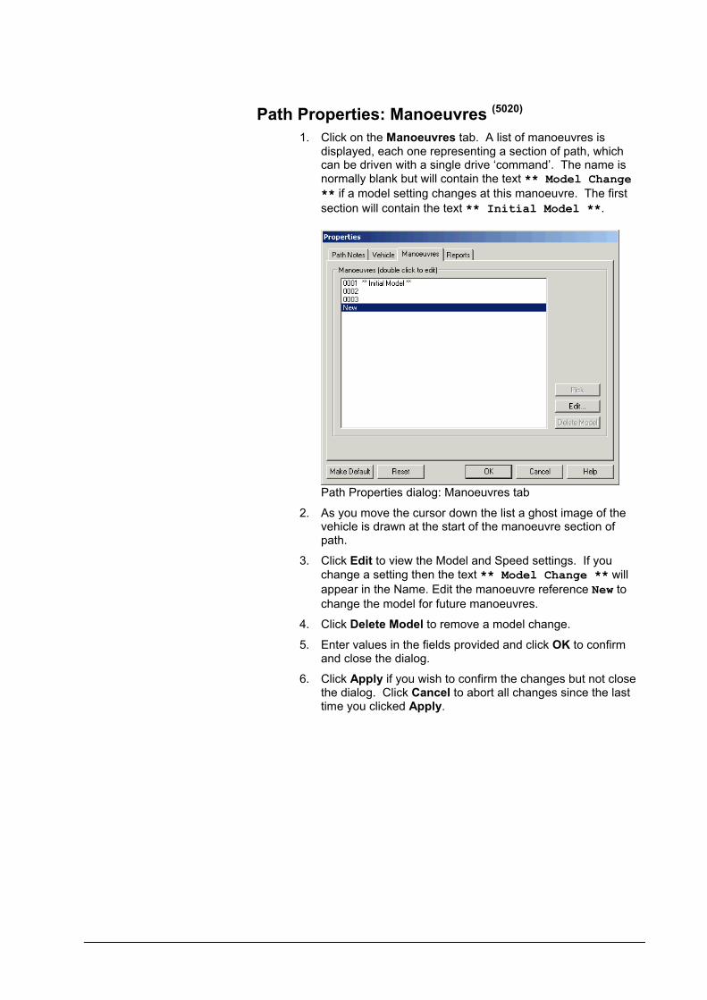
Path Properties: Manoeuvres (5020)
1. Click on the Manoeuvres tab. A list of manoeuvres is displayed, each one representing a section of path, which can be driven with a single drive ‘command’. The name is normally blank but will contain the text ** Model Change ** if a model setting changes at this manoeuvre. The first
section will contain the text ** Initial Model **.
Path Properties dialog: Manoeuvres tab
2. As you move the cursor down the list a ghost image of the vehicle is drawn at the start of the manoeuvre section of path.
3. Click Edit to view the Model and Speed settings. If you change a setting then the text ** Model Change ** will appear in the Name. Edit the manoeuvre reference New to change the model for future manoeuvres.
4. Click Delete Model to remove a model change.
5. Enter values in the fields provided and click OK to confirm and close the dialog.
6. Click Apply if you wish to confirm the changes but not close the dialog. Click Cancel to abort all changes since the last time you clicked Apply.

User Manual for AutoTrack Swept Paths: Editing paths 205
Path Properties: Manoeuvres: General (5040)
1. Click on the General tab.
Path Properties dialog: Manoeuvres: General tab
2. Edit the Description and Comments as required. The description is displayed in the manoeuvres list.
Path Properties: Manoeuvres: Speed
1. Click on the Speed tab.
2. See Settings: Speed.
Path Properties: Manoeuvres: Tracking Point
1. Click on the Tracking Point tab.
2. See Settings: Tracking Point.
Path Properties: Manoeuvres: Model
1. Click on the Model tab.
2. See Settings: Model.
Path Properties: Manoeuvres: Dynamics
1. Click on the Dynamics tab.
2. See Settings: Dynamics.
Path Properties: Manoeuvres: Transitions
1. Click on the Transitions tab
2. See Settings: Transitions.

Path Properties: Reports
1. Click on the Reports tab. A list of all current reports will appear.
Path Properties dialog: Reports tab
2. Click the + symbol to expand the explorer view and tick those elements that you want to include.
3. To edit a report see Settings: Reports.
Adjusting model settings (Roads only)Model settings apply from the point at which they are made until the next change of model. Model changes are indicated with an octagon around the relevant target point. See Drawing Settings: Model (not Rail)
(2070)for
more details.
To change the absolute steering limits
Properties button
1. Select the path that you want to edit.
2. Select Properties from the AutoTrack drop down menu or click the Properties button on the AutoTrack toolbar. The Path Properties dialog will appear.
3. Click the Manoeuvres tab.
4. Highlight the required manoeuvre and click the Edit button. The manoeuvre details dialog will appear.
5. Click the Model tab.The steering can be limited in three ways:-Select Limit steering to percentage to change the steering capability of your selected vehicle as a factor of the actual maximum steering angle.Select Limit steering to angle to set a new maximum steering angle.Select Limit steering to radius to specify the maximum steering angle in terms of an equivalent radius. The radius may be to the inside of the inner wheels, the outside of the

User Manual for AutoTrack Swept Paths: Editing paths 207
outer wheels, or the centreline of the steered axle.
To change the absolute articulation limits
Properties button
1. Select the path that you want to edit.
2. Select Properties from the AutoTrack drop down menu or click the Properties button on the AutoTrack toolbar. The Path Properties dialog will appear.
3. Click the Manoeuvres tab.
4. Highlight the required manoeuvre and click the Edit button. The manoeuvre details dialog will appear.
5. Click the Model tab.The articulation angles can be limited in two ways:-Select Limit to percentage to change the articulation limits of your selected vehicle as a factor of the actual maximum articulation angle.Select Limit to angle to set a new maximum articulation angle.
Adjusting speed settingsSpeed settings apply from the point at which they are made until the next change of model. Speed changes are indicated with an octagon around the relevant target point. See Drawing Settings: Speed
(2080)for more
details.
To change the design speed
Properties button
1. Select the path that you want to edit.
2. Select Properties from the AutoTrack drop down menu or click the Properties button on the AutoTrack toolbar. The Path Properties dialog will appear.
3. Click the Manoeuvres tab.
4. Highlight the required manoeuvre and click the Edit button. The manoeuvre details dialog will appear.
5. Click the Speed tab.
6. You may set different values for the Forwards Design Speed and the Reverse Design Speed.
Adjusting transition settings (not Rail)Turn transition types apply from the point at which they are made until the next change of model. Transition changes are indicated with an octagon around the relevant target point. See Drawing Settings: Transitions (not Rail)
(2085)for more details.
To change the turn transiton types
Properties button
1. Select the path that you want to edit.
2. Select Properties from the AutoTrack drop down menu or click the Properties button on the AutoTrack toolbar. The Path Properties dialog will appear.

3. Click the Manoeuvres tab.
4. Highlight the required manoeuvre and click the Edit button. The manoeuvre details dialog will appear.
5. Click the Transitions tab.
6. Tick Limit Forward Turn Rate or Limit Reverse Turn Rate to restrict the rate of application of steering lock when travelling forwards and backwards respectively.
Select Based Upon Speed to impose a turn rate that causes the overturn to increase with speed. The turn rate (degrees per unit of distance) will be calculated as follows:-R = A / V t
Select Based Upon Lock to Lock Distance to impose a limit that is fixed for all speeds. The turn rate (degrees per unit of distance) will be calculated as follows:-R = A / d
Where:-R is Max Turn Rate
A is Max Steering AngleV is Design Speed t is Lock to Lock Timed is Lock to Lock Distance
Select Based upon Circular Tangential Arc to follow a pure circular arc. This option is only available for forward turns.
7. Tick Turn on the spot at start of all forwards sections or Turn on the spot at start of all reverse sections to turn the steering instantaneously at each change of angle whilst the vehicle is travelling forwards or backwards respectively.
8. Tick Set optimum steering angle at start of path to allow the steering to turn to the best starting angle at the beginning of the path. Note that this option always applies to the start point regardless of which target point is currently being examined.
Adjusting the tracking point (not Rail)Tracking Point settings apply from the point at which they are made until the next change. Tracking Point changes are indicated with an octagon around the relevant target point. See Drawing Settings: Tracking Point (not Rail)
(2170)for more details.
To change the tracking point
Properties button
1. Select the path that you want to edit.
2. Select Properties from the AutoTrack drop down menu or click the Properties button on the AutoTrack toolbar. The Path Properties dialog will appear.
3. Click the Manoeuvres tab.
4. Highlight the required manoeuvre and click the Edit button. The manoeuvre details dialog will appear.

User Manual for AutoTrack Swept Paths: Editing paths 209
5. Click the Tracking Point tab.
6. Select the Front Tracking Point and Rear Tracking Point as required.
Adjusting dynamics settings (not Rail)Dynamics settings apply from the point at which they are made until the next change. Dynamics changes are indicated with an octagon around the relevant target point. See Drawing Settings: Dynamics (not Rail)
(2180)
for more details.
To change dynamics settings
Properties button
1. Select the path that you want to edit.
2. Select Properties from the AutoTrack drop down menu or click the Properties button on the AutoTrack toolbar. The Path Properties dialog will appear.
3. Click the Manoeuvres tab.
4. Highlight the required manoeuvre and click the Edit button. The manoeuvre details dialog will appear.
5. Click the Dynamics tab.
6. Tick the Limit for Dynamic Effects box to apply a turning radius limit based upon driver comfort and allowing for side friction and super elevation.
Vehicle details report
To insert a vehicle details report
Insert Profile button
1. Select the path whose vehicle details you wish to insert.
2. Select Insert Profile from the AutoTrack drop down menu or click the Insert Profile button on the AutoTrack toolbar.
3. A ghosted picture of the vehicle will appear at the cursor.
4. Move the mouse to position the report and left click to confirm.
5. To edit or disable the report see Viewing the properties of a path (Path Properties dialog).
To move a vehicle details report
1. Select the report that you want to move. Note that the report and its associated path and any other reports will appear selected.
2. Pick the grip at the centre of the front wheels of the first unit and holding the left mouse button down, move the details report as required. Release the mouse button to drop the report.
To remove a vehicle details report

Properties button
1. Select the report that you want to remove.
2. Select Properties from the AutoTrack drop down menu or click the Properties button on the AutoTrack toolbar.
3. Select the Reports tab.
4. Click the + next to Report 0001 to display the sub-reports and untick the Profile sub-report.
5. If you have more than one report listed (i.e. Report 0001, Report 0002, etc) then you will need to expand each in turn and make sure that the Profile report is disabled in each.
Placing discrete body outlines (5140)
To place discrete outlines
Place Outline button
You can add discrete outlines using the reports dialogs. However, there is a quick way to add them using the Place Outline command.
1. Select the path on which you wish to add discrete outlines.
2. Select Place Outline from the AutoTrack drop down menu or click the Place Outline button on the AutoTrack toolbar. The Place Outline dialog will appear.
Place Outline dialog
3. Tick the discrete elements that you want to add.
4. To place them, move the cursor until they appear at the required location on the path and left click to confirm. You can remove the selected outlines by reselecting the location.
The rule is:-If all the selected elements are present at the chosen location, then when you left click all the selected elements will be removed.If any of the selected elements are not present at the chosen location, then when you left click the missing selected elements will be added.
5. To remove a particular outline from a location tick just this outline type and select the location.
6. To quickly remove all outlines from a location tick all outline types and select the location twice (once to add any non-existent outlines and a second time to remove them all).

User Manual for AutoTrack Swept Paths: Editing paths 211
Extracting path dataSometimes there is a need to analyse paths in more detail than is possible in a CAD system. The Extract command allows you to save path data as text files which can then be imported into a spreadsheet program and further examined.
To extract path data
1. Select the path that you wish to extract data from.
NoteYou may only extract data for one path at a time.
2. Select Extract from the AutoTrack, Path menu. The Save As dialog will appear.
3. Select the file type (comma delimited or tab delimited), name the file and browse to the save location.
4. Click Save to confirm.
5. The file will contain the following data in columns:-
COUNTPOSITION XPOSITION YPOSITION ZDISTANCEMAX STEERING ANGLEMIN STEERING ANGLEACTUAL STEERING ANGLEPERCENTAGE OF MAX STEERING ANGLEUNIT 1 ANGLEUNIT 2 ANGLE…UNIT 1-2 ARTICULATION ANGLE…
Reading extracted data in Excel
The following is presented as a demonstration of how easy it is to obtain graphical plots of AutoTrack path data in Excel 2002. The procedure will vary in other spreadsheet programs.
1. Generate a short path with an articulated vehicle and extract the data as described in the previous section.
2. Open Excel.
3. Open the CSV file containing your extracted path data.
4. Select the columns labelled Actual Steering Angle and Unit 1-2 Articulation Angle by clicking on the column letter designator.
5. Select Chart from the Insert menu. The Chart Wizard will start.
6. Select Line graph and click Finish. A graph will be inserted showing steering angle and articulation angle varying with distance along the path.
7. The Chart Wizard has further options to allow you to enhance the graph.


User Manual for AutoTrack Swept Paths: Creating and editing vehicles 213
Swept Paths: Creating and editing vehicles
Although AutoTrack includes a wide range of predefined vehicles there will be cases where you will need a vehicle that is not listed. Between them, the Vehicle Wizard and the Advanced Editor allows you to create or edit almost any vehicle. And if you use your own vehicles regularly you may wish to create your own library of vehicles.
AutoTrack vehicle librariesAutoTrack is provided with a number of vehicles whose dimensions and characteristics have been pre-defined and which can be used immediately. In the UK version these vehicles are provided in a file called UK_xxx.ATL, where xxx is the most recent version of AutoTrack that can read it, e.g. UK_700.ATL. Such collections of vehicles are referred to as vehicle libraries. Additional vehicle libraries are available for different markets and can even be created by users themselves. However, to ensure that vehicle details do not change arbitrarily, there are restrictions on who can edit them. These restrictions require that users identify themselves if they wish to access a library to make changes. No password is needed simply to use a vehicle contained therein.
Access to vehicle libraries
Access to libraries is restricted using a username / password system such that before a library can be opened for editing they must enter his or her name and password. Only if the user is authorised will they be allowed to open the library. There are three levels of access:-
None
You may list the vehicles but cannot access the details. This is the status of any libraries that have not been purchased.
Read Only
You may use the vehicles but may not change them or add new vehicles. All libraries are initially opened Read Only.
Full Access
You may use, copy, edit, or create new vehicles and add or edit the users.
All Savoy vehicle libraries are Read Only.

Refer to Viewing and editing vehicles for details of how to open vehicle libraries and maintain users.
Access to vehicles in the Pool
Vehicle once in the Pool may be edited unless they have been driven. As soon as a vehicle is used in a path it can no longer be edited; it can however be copied and the copy edited.
NoteIf you make a copy of a vehicle in the same library it’s name (and those of all it’s units) are prefixed with the words ‘Copy of ’ to distinguish it from the original vehicle.
Compatibility with previous versionsAutoTrack can read vehicle library files back as far as AutoTrack 2, as well as WinTrack 2.x library files. It can also read AutoCAD drawings that contain data generated by earlier versions of AutoTrack and the vehicles contained therein. However, it cannot report upon or manipulate path data generated by earlier versions of either product.
Loading AutoTrack 2.x vehicle libraries
If you want to load v2.x libraries you will need the vehicle files and the corresponding library definition file (extension .DEF). If you do not have this file, then create a text file in the following format:-
{LIBRARY NAME} {VEHICLE FILE NAME}{VEHICLE FILE NAME}{VEHICLE FILE NAME}etc….
Where {VEHICLE FILE NAME} is the AutoCAD drawing file name (without the extension). So if you want to load an old library called “Any Old Library” consisting of three vehicle files, CAR.DWG, BUS.DWG and TRUCK.DWG then your DEF file should look like this:-
Any Old LibraryCARBUSTRUCK
To load an AutoTrack 2.x library
1. Place the DEF file along with the DWG files in the AutoTrack Library subdirectory.
2. Open the library explorer.
3. Right click and select Open Library from the menu.
4. Change the file type to AutoTrack 2.x and browse to find the DEF file.
5. Highlight the file and click Open.
6. The library will appear in the explorer as Imported AutoTrack v2.x vehicle library.
7. Right click and select Save Library As from the menu.
8. Name the file and click Save.

User Manual for AutoTrack Swept Paths: Creating and editing vehicles 215
To load an AutoTrack 2.x vehicle
If you want to load just one vehicle or don’t have the DEF file you can load individual AutoTrack 2.x vehicles into AutoTrack.
1. Make a copy of the AutoTrack 2.x vehicle file (the DWG file).
2. Load the AutoTrack 2.x vehicle file into AutoCAD.
3. Open the library explorer.
4. The AutoTrack 2.x vehicle will be listed in the Pool.
5. If you want to save the vehicle for future use then create a new library, drag the vehicle into it and save the library.
AutoTrack can be used alongside AutoTrack v2.x but not v3.x.
ImportantBecause AutoTrack v2.x made no distinction between front and rear axles AutoTrack assumes that the actual wheelbase is the greatest distance between any two adjacent axles. It is possible that this assumption may be incorrect in a few cases.
Viewing a vehicle in a library or the pool (Library Explorer dialog) (3510)
Vehicle Library button
Group by Vehicle Group button
Group by Vehicle Category button
1. Select Vehicle Library from the AutoTrack menu or click the Vehicle Library button on the AutoTrack toolbar. The Library Explorer will appear. For details of the vehicles see Vehicle Libraries.
Library Explorer dialog
2. If the library that you require is not loaded then select Open Library from the File menu in the Library Explorer, browse to find the library and click Open. A new Vehicle Library icon will appear in the Library Explorer with the name of the library beside it.
Group by Vehicle Classification button
Group by Vehicle Type button
Do Not Group button
Hide Library Level button
Insert/Remove Columns button
Vehicle Wizard button
Vehicle Diagram button
3. The grouped buttons at the top of the Explorer dialog represent display group options. Click the Group by Vehicle Group button, Group by Vehicle Category button, Group by Vehicle Classification button Group by Vehicle Type button or Do Not Group button to list the vehicles grouped accordingly when the library is expanded.
4. Click the Hide Library Level button to display all vehicles from all libraries together.
5. Click on the + symbol to expand the library or the pool.
6. Click the + symbol adjacent to the required by group, category or classification if necessary.
7. The arrow on the header bar allows you to list the data in ascending or descending alphanumeric order. Click on the arrow to change the order or click on another column header to sort by another item of data.
8. Below the buttons is an editable list box that allows you to search for text in all open vehicle libraries. Simply type the text in the field and click the Search button. The last 20 searches are saved and can be recalled by clicking on the arrow at the right hand end.
9. You can also search and download vehicles from the Savoy website using the Online Vehicle Library Explorer. To do this enter any required search text, tick the Online checkbox and click the Search button. See Finding vehicles online (Online Vehicle Library Explorer)
3580.
10. You can add or remove data from the display by clicking the Insert/Remove Columns button. See Finding vehicles online (Online Vehicle Library Explorer)
3580)
11. Highlight the required vehicle (indicated by a vehicle symbol dependant upon its type) and select Edit (or View if the Library is locked) from the Edit menu. The Vehicle Details dialog will appear.
12. If you wish to edit a Vehicle Group then highlight it and select Edit (or View if the Library is locked) from the Editmenu in the Library Explorer. The Vehicle Group dialog will appear.
13. To create a new vehicle or edit or view an existing vehicle using the vehicle wizard click the Vehicle Wizard button. For more details refer to The Vehicle Wizard.
14. To print a library, vehicle group or vehicle, select Print from the File menu or click the Print button. For more details refer to Printing library or vehicle details (Print dialog)
(5070).
15. Click the Vehicle Diagram button to display a picture of the current vehicle in a window adjacent to the Library Explorer. See Vehicle Diagram dialog
(3570))

User Manual for AutoTrack Swept Paths: Creating and editing vehicles 217
Finding vehicles online (Online Vehicle Library Explorer) 3580
Online checkbox
Search button
1. From the Vehicle Library Explorer, tick the Online checkbox and click the Search button to display the Online Vehicle Library Explorer.
2. The online libraries of vehicles are displayed hierarchically in much the same way as the local libraries. Click on the + symbol to expand a level or on the – to collapse it.
3. Once you are at vehicle level the same data columns are displayed as on the local Library Explorer. If you change the local data columns the online columns will change too.
4. You can change your search criteria without going back to the Library Explorer, simply enter the text in the box at the top and click Search.
5. At the left hand end of each vehicle there is a checkbox and thumbnail image. Tick the checkbox to select the vehicle for download to your PC. If you are not sure then move the cursor over the thumbnail to see a larger image with all the data. Click on the thumbnail image to keep the vehicle details on screen while you continue looking. If you click on another thumbnail then that image and data replaces the previous data.
6. Once you have selected your required vehicle(s) click the Download button. The vehicle(s) will be copied to your hard disk and will appear in a special library called Downloaded Vehicles. These are now accessible even without an internet connection.
NoteAnyone can browse the online libraries but you will need a current support, maintenance and updates contract to downloade them for use.
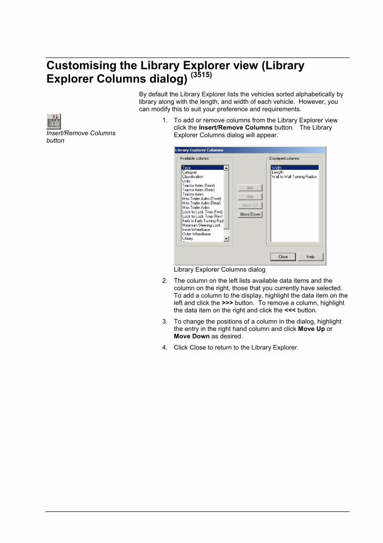
Customising the Library Explorer view (Library Explorer Columns dialog) (3515)
Insert/Remove Columns button
By default the Library Explorer lists the vehicles sorted alphabetically by library along with the length, and width of each vehicle. However, you can modify this to suit your preference and requirements.
1. To add or remove columns from the Library Explorer view click the Insert/Remove Columns button. The Library Explorer Columns dialog will appear.
Library Explorer Columns dialog
2. The column on the left lists available data items and the column on the right, those that you currently have selected. To add a column to the display, highlight the data item on the left and click the >>> button. To remove a column, highlight the data item on the right and click the <<< button.
3. To change the positions of a column in the dialog, highlight the entry in the right hand column and click Move Up or Move Down as desired.
4. Click Close to return to the Library Explorer.

User Manual for AutoTrack Swept Paths: Creating and editing vehicles 219
Vehicle Diagram dialog (3570)
Zoom Extents button
Zoom In button
Zoom Out button
Increase Steering Angle button
Decrease Steering Angle button
Increase Articulation Angles button
Decrease Articulation Angles button
AutoScale button
Show Datums button
Show Dimensions button
Show Loads button
Show Other Outlines button
Show Simple Body Outlines button
1. The Vehicle Diagram dialog shows a scale picture of the current vehicle. Initially the picture is centred on the geometric centre of the vehicle but you can change the focus by simply clicking on the picture.
Vehicle Diagram dialog
2. The principle dimensions are listed below the diagram.
NoteOverall Width follows the general convention and excludes the width of wing mirrors.
3. Click the Zoom In button to double the view scale and the Zoom Out button to halve the view scale. Note that using either command disables the AutoScale feature (see below).
4. Click the Zoom Extents button to restore a full size view of the entire vehicle. Using this command re-enables the AutoScale feature (see below).
5. You can increase or decrease the steering angle shown using the Increase Steering Angle button and Decrease Steering Angle button respectively.
6. Likewise the articulation angles can be changed with the Increase Articulation Angles button and Decrease Articulation Angles button respectively.
7. Depress the AutoScale button if you want the picture to zoom to extents when you highlight a new vehicle. You may disable this to make it easier to see the relative sizes of the vehicles as you scan through a library. This option is automatically disabled if you zoom in or out manually but is re-enabled if you zoom to extents.
8. Depress the Show Datum button to display the reference datum for each unit. This also shows the location of the

Show Turn Template button
Show Body button
Show Chassis button
Show All button
Show Elevation button
driver or pilot.
9. Depress the Show Dimensions button to display dimensions on the diagram.
10. Depress the Show Loads button to display load outlines and/or the Show Other Outlines button to display any and all other outline types.
11. Depress the Show Simple Body Outlines button to hide the detailed outline and display just a silhouette of the vehicle.
12. Depress the Show Turn Template button to show 30, 60, 90, 120, 150 & 180 degree turn templates for front steered vehicles only. For details of how to print these templates refer to Printing library or vehicle details (Print dialog)
(5070).
NoteYou can also create Turn Templates using the Template Generator. See Template Generator.
13. Click the Show Body button to display just the bodies, Show Chassis button to see just the chassis elements or Show All button to see both. The colours are the default colours used for reporting. Click Show Elevation to display a side view of the vehicle.

User Manual for AutoTrack Swept Paths: Creating and editing vehicles 221
Creating a new library (Library Details dialog) (3520)
Vehicle Library button
1. Select Library, Explore from the AutoTrack menu or click the Vehicle Library button on the AutoTrack toolbar. The Library Explorer will appear.
2. Select New Library from the File menu in the Library. The Library Details dialog will appear.
Library Details dialog
3. Click the appropriate tab to edit or view the settings.
4. Edit the data as required and click OK to confirm when you are satisfied. Click Cancel to abort all changes and close the dialog.
Library Details: Library
1. Click the Library tab.
2. Give the library a meaningful Name.
3. The Version and Notes fields are provided for additional information and may be used at your discretion.
4. The File Name is read only and will be filled in when the file is saved.
Library Details: Users (3530)
NoteYou may only add new users or edit existing users in libraries to which you have full access rights.
1. Click on the Users tab.

Library Details: Users
2. On a new library all users have full access as indicated by the default entry in the Users table. At least one user in the table must have full access before you may downgrade the default Any User rights.
To add a new user
1. On the Library Details dialog click New. The New User dialog will appear.
New User dialog
2. Enter the new User Name. Depending upon how you want to restrict access, this may be a specific person or a department name.
3. Enter the Password and then repeat it in the Validate Password field. This checks that you typed the password correctly. If you do not enter a password the named user will be able to unlock the library without typing a password.
4. Finally set the Access Level. We recommend that you add any users that you want to have full access and then downgrade the default Any User to Read Only.
5. Even tighter restrictions can be placed by downgrading Any User to No Access and adding Read Only users as required. However, this may prove problematic in practice.
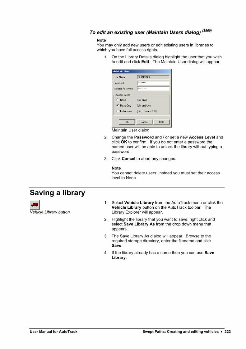
User Manual for AutoTrack Swept Paths: Creating and editing vehicles 223
To edit an existing user (Maintain Users dialog) (3560)
Note You may only add new users or edit existing users in libraries to which you have full access rights.
1. On the Library Details dialog highlight the user that you wish to edit and click Edit. The Maintain User dialog will appear.
Maintain User dialog
2. Change the Password and / or set a new Access Level and click OK to confirm. If you do not enter a password the named user will be able to unlock the library without typing a password.
3. Click Cancel to abort any changes.
NoteYou cannot delete users; instead you must set their access level to None.
Saving a library
Vehicle Library button
1. Select Vehicle Library from the AutoTrack menu or click the Vehicle Library button on the AutoTrack toolbar. The Library Explorer will appear.
2. Highlight the library that you want to save, right click and select Save Library As from the drop down menu that appears.
3. The Save Library As dialog will appear. Browse to the required storage directory, enter the filename and click Save.
4. If the library already has a name then you can use Save Library.
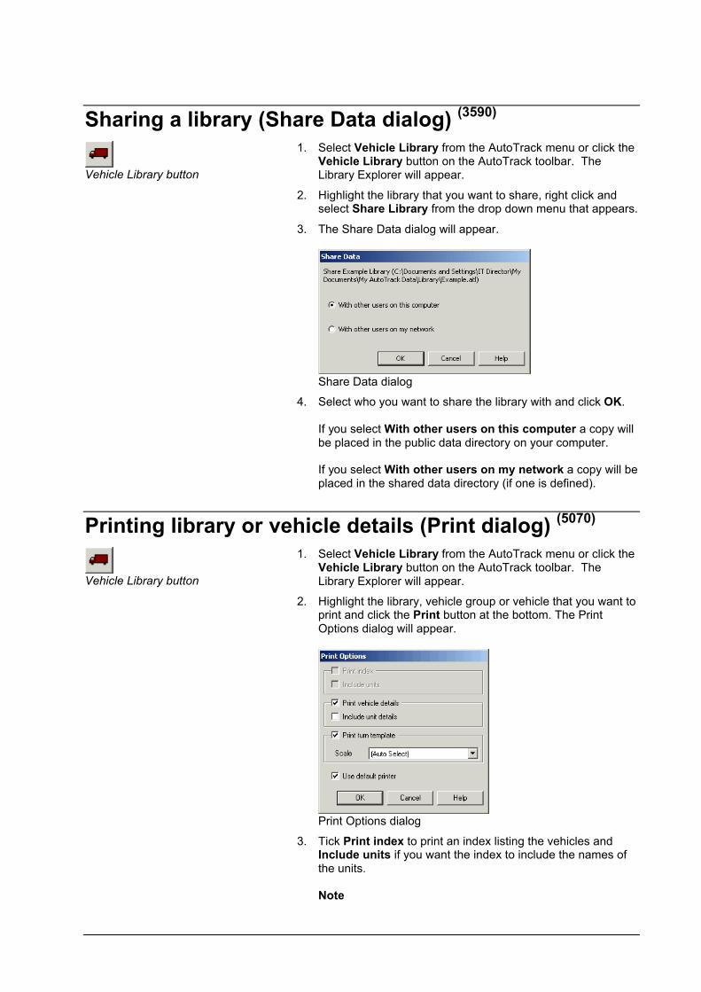
Sharing a library (Share Data dialog) (3590)
Vehicle Library button
1. Select Vehicle Library from the AutoTrack menu or click the Vehicle Library button on the AutoTrack toolbar. The Library Explorer will appear.
2. Highlight the library that you want to share, right click and select Share Library from the drop down menu that appears.
3. The Share Data dialog will appear.
Share Data dialog
4. Select who you want to share the library with and click OK.
If you select With other users on this computer a copy will be placed in the public data directory on your computer.
If you select With other users on my network a copy will be placed in the shared data directory (if one is defined).
Printing library or vehicle details (Print dialog) (5070)
Vehicle Library button
1. Select Vehicle Library from the AutoTrack menu or click theVehicle Library button on the AutoTrack toolbar. The Library Explorer will appear.
2. Highlight the library, vehicle group or vehicle that you want to print and click the Print button at the bottom. The Print Options dialog will appear.
Print Options dialog
3. Tick Print index to print an index listing the vehicles and Include units if you want the index to include the names of the units.
Note

User Manual for AutoTrack Swept Paths: Creating and editing vehicles 225
These options are disabled if you selected a vehicle.
4. Tick Print vehicle details to print details for the selected vehicles including a dimensioned scale diagram. Tick Include unit details if you want full details of every unit.
5. Tick Print turn template to print 30, 60, 90, 120, 150 & 180 degree turn templates for the selected vehicles. Select the scale from the drop down list box or let AutoTrack select it for you. Note that the printed output includes a check point to allow you to check for stretching of the paper.
6. Tick Use default printer if you do not want to see the printer settings when you click OK and then click OK to proceed.
7. The Print dialog will appear if you did not opt to use the default printer. Adjust the printer settings if necessary and click OK.
Copying vehicles and units using drag and dropVehicles are automatically copied to the Pool when they are driven but you may wish to edit a vehicle before driving it or indeed build your own library of frequently used vehicles.
To copy a vehicle to the pool, select it, drag it over the Pool symbol and drop it. If you wish to copy it to another library you will need full access rights in the destination library. The cursor will change to a no entry symbol to indicate areas where you may not drop the vehicle.
You can also make copies of vehicles within libraries in the same way; in this case the names of the vehicle and its constituent units are prefixed with the words ‘Copy of ‘, to distinguish them from the originals. If you drag a vehicle to a new group within the same library it will be moved (notcopied). If you want it to be copied then hold down the <Ctrl> key while you drag. This is basically the same functionality as you will be familiar with in Windows Explorer.
Units may be copied in the same way but can only be copied to another vehicle. Select the unit and drag and drop it over the required vehicle. The unit will be added to the end of the vehicle but may be moved forward by editing the vehicle details.
Entire vehicles can also be added to the end of other vehicles in the same way. In this case all the units that make up the dragged vehicle are added to the end of the target vehicle.
Building vehicles using drag and dropUsing the drag and drop facility new vehicles can be constructed from existing vehicles quite quickly. However, be sure to check that the articulation angles between units are appropriate for your new vehicle.
Using tractors as trailers
If you drop a tractor type unit onto another vehicle it's type AutoTrack will change it's type to Tractor used as trailer. AutoTrack will then ignore the steering limits of the tractor when the vehicle is driven. It will also check that a coupling exists at the rear of the existing vehicle and at the front of the dropped tractor. In most cases you should not need to make any further changes to the vehicle. However, if it was necessary for AutoTrack to add couplings you might need to edit the coupling details.
Towbar type aircraft tugs

To model aircraft being towed with a towbar type tug you will need to change the front axle type to Drawbar. You will also need to set a front coupling at the end of the drawbar.
Towbar-less aircraft tugs
If using the drawbar-less type of tug you should set the articulation limits for the coupling to the maximum nosewheel angle.
Unlocking a library (Unlock Library dialog) (3550)
1. Highlight the library that you want to unlock, right click and select Unlock Library from the drop down menu that appears. If a password has been set for the library, the Unlock Library dialog will appear. Otherwise, the library will be unlocked and you should refer to step 3.
Unlock Library dialog
2. Enter your User Name and Password and click OK.
3. You will be granted whatever rights you have within the library. Thus, if you have full access rights within the current library then you will be able to edit vehicles in the unlocked library; if, on the other hand you only have read only rights then you will only be able to drive and copy the vehicles.
Creating a new group
Vehicle Library button
1. Select Vehicle Library from the AutoTrack menu or click the Vehicle Library button on the AutoTrack toolbar. The Library Explorer will appear.
2. Highlight the library that you want to add a group to.
3. Right click and select New, Group from the menu. The Vehicle Group dialog will appear.
4. Edit the details and click OK to confirm.

User Manual for AutoTrack Swept Paths: Creating and editing vehicles 227
Vehicle Group dialog (4040)
1. The Vehicle Group dialog lists the vehicle group details.
Vehicle Group dialog
54. Edit the Name, Category and Classification as required and click OK to confirm.
Viewing a vehicle used on a particular path
Properties button
1. Select the path and select Properties, Path from the AutoTrack menu or click the Properties button on the AutoTrack toolbar.
2. Click the Vehicle tab. The Vehicle Details dialog will appear.
Viewing or editing an existing vehicle
Vehicle Library button
Vehicle Wizard button
1. Select Vehicle Library from the AutoTrack menu or click the Vehicle Library button on the AutoTrack toolbar. The Library Explorer will appear.
2. Highlight the vehicle whose details you wish to view or edit. Note that you cannot edit Savoy library vehicles or vehicles in other locked libraries directly but you can view their details or edit a copy.
3. Click the Vehicle Wizard button or right click and select Edit(or View if the vehicle is locked) from the menu that appears. The Vehicle Wizard will appear (see The Vehicle Wizard).
4. To edit a locked vehicle (e.g. a library vehicle) highlight itm right click and select Edit a Copy. AutoTrack will make a copy of the vehicle in the Pool and open it in the Vehicle Wizard.

Creating vehiclesBy default new vehicles are created using the Vehicle Wizard. However, you can switch to the advanced editor from any page of the wizard and once the vehicle is created you can even start editing in the advanced editor if you prefer.
To create a new vehicle
Vehicle Library button
Vehicle Wizard button
1. Select Vehicle Library from the AutoTrack menu or click the Vehicle Library button on the AutoTrack toolbar. The Library Explorer will appear.
2. Make sure that the cursor is not on a vehicle, then right click and select New, Vehicle from the menu that appears or click the Vehicle wizard button.
NoteAll new vehicles are created in the Pool even if the cursor is over an editable library or vehicle group. This minimises the risk that you corrupt an existing library.
3. The Vehicle Wizard will appear (see The Vehicle Wizard).

User Manual for AutoTrack Swept Paths: Creating and editing vehicles 229
The Vehicle WizardThe Vehicle Wizard allows you to define simple vehicles. The wizard cannot edit the following:-
More than 7 unitsNon-identical axlesDifferent front and rear lock to lock timesSteering linkagesSelf-steered or retracted axles
If you try to edit a vehicle that has more than 7 units you will be placed in the advanced editor.
On every page of the wizard there is an Advanced button that takes you to the advanced editor. If you wish to edit data that falls into one of the above categories go to the advanced editor then return to the wizard.
Also on every page is a Finish button. This is only active for vehicles that are being edited and not for those being created for the first time.
The wizard displays different screens depending upon the vehicle type.
Some tips for defining trams (Rail only)
All axles on a tram must, by definition, be guided. Each front or rear axle group is reduced to an effective contact point (ECP) and these are used to calculate the movement of the tram. However, it is not always easy to determine whether an axle, or its wheels, are fixed or free to turn, and if you define them incorrectly the tram may be undriveable. There are two rules that must be observed when defining a tram in order to avoid undriveable vehicles.
1. Each tram must have at least one unit with 2 guide points (i.e. a front axle group and a rear axle group) but this need not necessarily be at the end of the tram.
2. There must be only one guide point adjacent to each articulation point. For example, if you define a rear guide point (axle group) on unit 2 then there must not be a front guide point on unit 3; and conversely, if there is no rear guide point on unit 2 then there must be a front guide point on unit 3.
Note that it is implicit in these rules that the first unit must have a front axle and the last unit must have a rear axle.
You should consider the following when defining a new tram:
Which unit is the 2-ECP unit ?
Most trams have a clear candidate for the required double ECP unit. However, if it is unclear you should bear in mind that a two axle bogie cannot be regarded as two separate contact points if the bogiearticulates with respect to the unit chassis. If the bogie does not articulate with respect to the unit chassis then you can consider the centres of the two axles of the bogie as separate effective contact points.
Where are the pivot points ?
The pivot points are where the tram chassis articulates. The tram chassis (and therefore the tram body) is assumed to be rigid between the pivot points.

Vehicle wizard: Name (7000)
Vehicle Wizard: Name tab
1. Enter the vehicle Name, Description and Source. Even though the Description and Source fields are not compulsory we nevertheless recommend that you complete them since they are useful reminders when you come to reuse the vehicle at a later date.
2. Enter the Vehicle type. You may select from a variety of steered vehicles, an aircraft or a tram. You may not select a vehicle type Tram if you have not purchased the Rail version. Likewise, you may only select a vehicle type Tram if you only have a licence for the Rail version. Your selection here affects the data your have to supply. For example, if you select a tram your vehicle will have rail type wheels and you will be asked for details of the pantograph.
3. Enter the Number of units.
NoteA unit with a drawbar front axle is regarded as a single unit.
4. Click the Advanced button to go to the Vehicle Details dialog.
5. Click Next to move to the next page.
NoteThroughout the wizard, if you have an invalid value you will not be permitted to go to the next page. You can, of course, also move backwards through the wizard using the Backbutton but note this is not a cancel button and retains any edits that you make on the current page.

User Manual for AutoTrack Swept Paths: Creating and editing vehicles 231
Vehicle wizard: Axles (7010)
Vehicle Wizard: Axles tab
1. Enter the Number of front axles. The first unit must have at least a front axle and the last unit must have at least a rear axle.
2. Drawbar trailers: If you specify front axles on the trailer of a steered vehicle the wizard assumes you want a drawbar.
3. Self-steered / retracted axles: Click the Advanced button to use the advanced vehicle editor and tick the Self-steered and / or Retracted box on the relevant axles.
4. Steering linkages: Click the Advanced button to use the advanced editor and tick the Linkage box.
5. Enter the Wheels on each axle. This is the total number of wheels on each axle so if there is only one wheel on each side you should enter 2 in this field. Wheels are generally assumed to be at the ends of the axles except for aircraft main undercarriage wheels which are at specified spacing.
6. Evenly spaced or specified spacing wheels: Click the Advanced button to use the advanced vehicle editor and select Evenly spaced or Specified spacing from the wheel position drop down box on each axle.
7. Enter the Front track width. All axles are assumed to be identical. Track width must be non-zero.
8. Non-identical track widths: Click the Advanced button to use the advanced vehicle editor and set the Outer face wheel track on each axle.
9. Do the same for the rear axles.
10. Click Next to move to the next page.

Vehicle wizard: Wheelbase (7020)
Vehicle Wizard: Wheelbase tab
1. Enter the Wheelbase - the distance between the innermost front and rear axles (or, if there are only axles at one end between the axles and the coupling at the other end). AutoTrack automatically calculates the centroids of the axle groups to calculate the effective wheelbase.
2. Manual setting of the effective wheelbase: Click the Advanced button and use the advanced editor to set the effective front and / or rear axle offset.
3. If you have more than one front or rear axles then you must enter appropriate values for Front axle spacing and Rear axle spacing. This is the distance between any two adjacent axles. The wizard assumes that the axles are evenly spaced, i.e. that the distance between all pairs of adjacent axles is the same.
4. Unevenly spaced axles: Click the Advanced button and use the advanced editor to set the offset of each axle.
5. Click Next to move to the next page.

User Manual for AutoTrack Swept Paths: Creating and editing vehicles 233
Vehicle wizard: Drawbar (7050)
Vehicle Wizard: Drawbar tab
1. Any steered vehicle trailer that has front axles is assumed to be a drawbar trailer.
2. The Length of drawbar is measured from the coupling to the preceding unit to the centre of the axle pivot.
3. The Drawbar articulation angle must be non-zero.
4. Click Next to move to the next page.

Vehicle wizard: Steering (not Rail) (7030)
Vehicle Wizard: Steering tab
1. Most vehicles will have front wheel steering but if your vehicle is one of the exceptions then select Rear Wheels or even Rear Coupling from the Steering drop down box.
2. Enter a value for the Lock to lock time. This is assumed toapply when the vehicle travels forwards or backwards and must be non-zero.
3. Different lock to lock rates for forwards and reverse: Click the Advanced button and use the advanced editor.
TipLock to lock time is a term that Savoy Computing introduced way back in the eighties. Whilst it is a useful way to describe the steering characteristics of a vehicle it is nevertheless a parameter that is little used in the motoring industry. Far more common is the number of turns of the steering wheel lock to lock. Clearly the two parameters are closely related and it may be useful when defining new vehicles to think in terms of number of turns lock to lock. Of course the time it takes to complete one turn of the wheel may vary between vehicles according to steering wheel size, resistance to turning and other factors.
4. Click Next to move to the next page.

User Manual for AutoTrack Swept Paths: Creating and editing vehicles 235
Vehicle wizard: Manoeuvrability (7040)
Vehicle Wizard: Manoeuvrability tab
1. Most source specify vehicle turning as either kerb to kerb radius or wall to wall radius. However it can also be specified as a maximum wheel angle or as a steering angle. Select the appropriate option and enter either the turning radius in the Minimum Turning Circle Radius field or theangle in the Maximum Angle field. Either must be greater than zero.
2. Click Next to move to the next page.

Vehicle wizard: Couplings (7060)
Vehicle Wizard: Couplings tab
1. The wizard automatically adds a front coupling to all trailers and a rear coupling to all preceding units. The Coupling offset is measured from the innermost rear axle.
2. You may add an additional front coupling to the front unit or a rear coupling to the last unit if you wish.
3. The Maximum articulation angle must be non-zero.
4. Click Next to move to the next page.

User Manual for AutoTrack Swept Paths: Creating and editing vehicles 237
Vehicle wizard: Body (7070)
Vehicle Wizard: Body tab
1. Enter values for the Body length and Body width. Both must be greater than zero. You will be warned if the body comprises multiple shapes and given the opportunity to reduce them to a simple bounding rectangle.
2. To create or edit bodies made up of multiple shapes: Click the Advanced button to use the advanced editor and edit the shapes as necessary.
3. The Rear Overhang is measured from the innermost rear axle (or the rear coupling if there is no rear axle) and may be negative if the back of the body is in front of the rear axle.
4. The vehicles are all supplied without wing mirrors defined. Ifyou would like to see the effect of wing mirrors tick Add wing mirrors.
WarningThe default wing mirrors will not be ideal for all vehicles and we recommend that you check the location and size if they are critical in your scheme.
5. Finally, select a Body Shape from the drop down list.
6. Click Next to move to the next page.

Vehicle wizard: Tractor body (7075)
Vehicle Wizard: Tractor Body
1. The Tractor body page allows you to create more realistic looking bodies for articulated vehicle haulers.
2. The Cab length is the length of the cab itself.
3. The Chassis width is the width of the chassis behind the cab.

User Manual for AutoTrack Swept Paths: Creating and editing vehicles 239
Vehicle wizard: Tram body (trams only) (7080)
Vehicle Wizard: Tram body tab
1. By default tram bodies are rectangular. This tab allows you to define more accurate end shapes for your trams.
2. The Taper width is amount by which the end of the tram body narrows on each side at the end. For example, if the uniform body width is 2m and the end width is 1m then the taper width is 0.5m.
3. The Taper length is the distance from the start of the body width reduction to the end of the tram body.
4. If you specify a negative End radius the end of the tram will be concave (i.e. curved inwards instead of outwards). This is used on the trams we provide to represent the inter-car turntable at articulation points.
5. Click Next to move to the next page.

Vehicle wizard: Aircraft wings (aircraft only) (7090)
Vehicle Wizard: Aircraft Wings tab
1. All except one of the fields on this tab have default values based upon the length or span of the aircraft. We must stress that none of the default values should be regarded asrecommended or accurate in any way. Some will be more critical than others and we encourage you to overwrite them with accurate dimensions.
2. The Wing Tip Leading Edge Offset is a particularly important dimension and can have a significant effect on the swept envelope.
3. Click Next to move to the next page.

User Manual for AutoTrack Swept Paths: Creating and editing vehicles 241
Vehicle wizard: Aircraft Tailplane (aircraft only) (7100)
Vehicle Wizard: Aircraft Tailplane tab
1. Again most of the fields on this tab have default values based upon the length or span of the aircraft. Whilst these dimensions are likely to be less critical than those of the wings, nevertheless we must stress that none of the default values should be regarded as recommended or accurate in any way and we encourage you to overwrite them with accurate dimensions.
2. Click Next to move to the next page.

Vehicle wizard: Aircraft Fuselage (aircraft only) (7110)
Vehicle Wizard: Aircraft Fuselage tab
1. The dimensions on this screen are unlikely to be critical. Nevertheless, it is still worth entering accurate data.
2. Click Next to move to the next page.
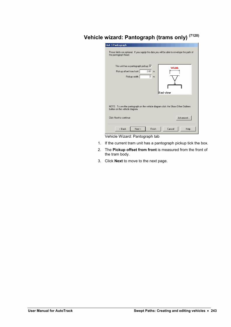
User Manual for AutoTrack Swept Paths: Creating and editing vehicles 243
Vehicle wizard: Pantograph (trams only) (7120)
Vehicle Wizard: Pantograph tab
1. If the current tram unit has a pantograph pickup tick the box.
2. The Pickup offset from front is measured from the front of the tram body.
3. Click Next to move to the next page.
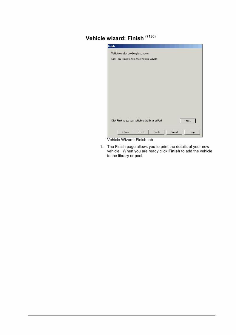
Vehicle wizard: Finish (7130)
Vehicle Wizard: Finish tab
1. The Finish page allows you to print the details of your new vehicle. When you are ready click Finish to add the vehicle to the library or pool.

User Manual for AutoTrack Swept Paths: Creating and editing vehicles 245
The Advanced EditorThe advanced editor has fewer restrictions than the wizard and allows you to define details that may not be possible using the wizard. However, the wizard preserves advanced settings defined using the advanced editor and consequently you can safely switch between editors as the need arises.
Vehicle Details dialog (4050)
The Vehicle Details dialog gives an overview of the complete vehicle, and lists the units that it comprises.
Vehicle Details dialog
1. The Name, Type, Category and Classification of the selected vehicle appear at the top of the dialog. Beneath that the units that comprise the vehicle are listed with the front unit at the top. Vehicle Category and Classificationare merely sort criteria used in the Library Explorer and have no bearing on how the vehicle behaves. However, you will not be able to create vehicles of type tram unless you are licensed to use the AutoTram module; likewise you will not be able to create any of the various steered vehicle types unless you are licensed to use AutoTrack.
2. Click the button next to the Name field to enter Source, Description and Notes.
3. Select a unit and click the View or, if you have appropriate rights, the Edit button to check the details of a specific unit. The Unit Details dialog will appear.
4. Click New to add a Unit to the vehicle. This will display a blank unit details dialog for you to create a completely new unit (see Unit Details dialog). If you want to add an existing unit to the vehicle, then drag it onto the vehicle in the Library Explorer dialog.
5. Select a unit and click Remove to remove it from the vehicle.

6. You can reorder units using the Move Up button. Select a unit and click Move Up. The selected unit will be moved up one place.
7. The only editable column in the lower grid is Max. Artic., the maximum articulation angle. This value is used in preference to those defined in the coupling details if it is lower.
8. The unit names can only be edited in the Unit Details dialog.
Unit Details dialog (4060)
The Unit Details dialog shows the detailed dimensions and parameters of individual units. When defining units we recommend that wherever possible you enter the actual dimensions and allow AutoTrack to calculate the effective dimensions.
1. Click on the appropriate tab to view or edit details.
Unit Details dialog: Unit tab
2. Enter values in the fields provided and click OK to confirm and close the dialog.
3. Click Apply if you wish to confirm the changes but not close the dialog. Click Cancel to abort all changes since the last time you clicked Apply.

User Manual for AutoTrack Swept Paths: Creating and editing vehicles 247
Unit Details: Unit
1. Click on the Unit tab.
55. Name may be anything but make sure that similar vehicles with different drive characteristics are clearly identified to prevent incorrect use. Click the button next to the Name field to enter Source, Description and Notes.
56. Unit Type may be Tractor, Trailer, Tractor Used as Trailer, Towbar, Suspended Unit or Tram / Guided Unit:-
Tractors are always the driven (and steered) unit and must therefore have at least a front axle and steering characteristics. Trailers have no steering parameters and may front and rear or just rear axle groups. Setting Tractor Used as Trailer forces AutoTrack to ignore the steering criteria for this unit and treat the remaining data as if it were a trailer. Suspended Units have no axles and therefore no steering capability.A Tram / Guided Unit is assumed to be guided by rails or similar and therefore has no steering capability. The unit may have front and / or rear axles or no axles but any axles must be guided. A Towbar is essentially the same as a suspended unit and has neither front nor rear axles and no steering.
As you edit the Type the relevant data tabs will appear and disappear.
57. Vehicle Category and Classification are merely sort criteria used in the Library Explorer and have no bearing to how the unit behaves.
58. The Datum is the reference point for all dimensions on the unit. It may be set to the front most or rearmost point on the body, the front or rear primary axle, or the front or rear coupling.
59. If you unit has a front axle tick Front Axle. Likewise Rear Axle.
60. The distance from the datum to the Innermost Front Axleand Innermost Rear Axle must be specified. Obviously if the selected datum is one or other of these values then the appropriate dimension will be zero. The values are directional as indicated by the text that follows the field and the direction in which the unit is facing. You will not be able to edit the front axle offset if you have a drawbar front axle and a front coupling datum.
NoteThe difference between the Innermost Front Axle offset and the Innermost Rear Axle offset is the Actual Wheelbasereferred to in WinTrack v2.x.
61. Both front and rear axle groups are equivalenced to single effective axles. The position of these effective axles is dependent upon a number of factors including the axle and steering geometry and the tyre dimensions. It is the effective

axle positions that determine how the vehicle moves. By default AutoTrack calculates the positions of the effective axles for you but in some cases it is useful to specify the position manually.
NoteSince the effective axle positions determine how the unit turns so we recommend that you allow AutoTrack to calcuate the value in most cases.
62. If you wish to set the Effective Front Axle Offset or Effective Rear Axle Offset manually then untick the relevant Use Calculated Value and enter the offset using the same direction convention as the Innermost Front Axle bearing in mind the direction drop down box.
NoteYou cannot manually specify an effective axle offset to an axle that is linked.
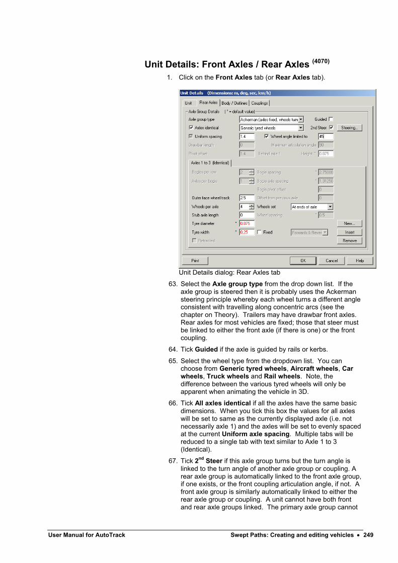
User Manual for AutoTrack Swept Paths: Creating and editing vehicles 249
Unit Details: Front Axles / Rear Axles (4070)
1. Click on the Front Axles tab (or Rear Axles tab).
Unit Details dialog: Rear Axles tab
63. Select the Axle group type from the drop down list. If the axle group is steered then it is probably uses the Ackerman steering principle whereby each wheel turns a different angle consistent with travelling along concentric arcs (see the chapter on Theory). Trailers may have drawbar front axles. Rear axles for most vehicles are fixed; those that steer must be linked to either the front axle (if there is one) or the front coupling.
64. Tick Guided if the axle is guided by rails or kerbs.
65. Select the wheel type from the dropdown list. You can choose from Generic tyred wheels, Aircraft wheels, Car wheels, Truck wheels and Rail wheels. Note, the difference between the various tyred wheels will only be apparent when animating the vehicle in 3D.
66. Tick All axles identical if all the axles have the same basic dimensions. When you tick this box the values for all axles will be set to same as the currently displayed axle (i.e. not necessarily axle 1) and the axles will be set to evenly spaced at the current Uniform axle spacing. Multiple tabs will be reduced to a single tab with text similar to Axle 1 to 3 (Identical).
67. Tick 2nd
Steer if this axle group turns but the turn angle is linked to the turn angle of another axle group or coupling. A rear axle group is automatically linked to the front axle group, if one exists, or the front coupling articulation angle, if not. A front axle group is similarly automatically linked to either the rear axle group or coupling. A unit cannot have both front and rear axle groups linked. The primary axle group cannot

have linked steering and neither can a fixed axle group.
WarningIf you create a linked Ackerman multi-axle group then even if you set a linkage ratio of zero some of the wheels will still turn reflecting the Ackerman axle type.
68. Click the 2nd
Steer button to enter details of the steering linkage ratios. See Unit Details: Axle Groups: Secondary Steering Details
(4090)below.
69. Tick Uniform axle spacing if all the axles in the group are the same distance apart and enter a value in the field. Identical axles are deemed to be evenly spaced.
NoteAlthough a default value is provided for the axle spacing we strongly recommend that you obtain an accurate figure and overwrite this.
70. Tick Wheel angle limited if you know the maximum angle that any wheel in the group can turn and enter the angle in the field provided. Note that if the axle group is of the Ackerman type all wheels will turn by different amounts; in this case you should enter the greatest angle of any wheel in the group.
NoteYou can only limit the turning of secondary steering or self-steered axles in this way. The primary steering limit may be adjusted on the Steering Details tab. See Unit Details: Steering
(4150).
WarningWhen the limiting wheel angle is reached the steering is recalculated based upon the value of the controlling or primary steering angle and the limiting angle. This tends to force the cut-in point towards the limited axle.
71. If you are defining a drawbar axle group, then enter the Drawbar length. Note that the coupling (if any) at the end of the drawbar must be specified in the Couplings tab.
72. Also, if defining a drawbar, enter the Maximum articulation angle which is the angle between the drawbar and the unit to which it is permanently attached.
73. If you are defining a nosewheel, bogie or drawbar axle group then you must specify the Axle group pivot offset. This is the distance in front of axle 1 on front axle groups and the distance behind axle 1 on rear axle groups.
74. On units with tyred wheels the Outer face wheel track is measured over the outer faces of the outermost tyres on an axle. It is most important that this value is correct if you are specifying steering turn angle by kerb to kerb turning circle radius. Note that on Pendel axles this dimension is measured to the outer faces of each sub-axle.
On units with rail wheels the Rail gauge is measured between the faces of the wheels in contact with the inner faces of the rails.

User Manual for AutoTrack Swept Paths: Creating and editing vehicles 251
75. Certain vehicles can have axles lifted from road contact when unloaded. Tick Retracted to specify an axle of this type. Note that you cannot define all axles in a group as retracted so by definition you cannot change this setting if the group only consists of one axle or if all axles are identical. The only exception to this rule is the primary steered axles of a tractor used as a trailer which may be retracted.
76. Bogies per row and Bogie spacing apply only to Pendel axles and each tab represents a row of bogies. Bogies per row is the number of bogies in each row across the width of the unit. Bogie spacing is the distance between the pivot points of each bogie. You can specify irregular spacings by entering values as "1.5,2.1,1.5". In this case the first spacing is the distance between the outermost bogie and the adjacent bogie, the second value is the distance between the next two bogies and so on. The last value is assumed to apply to any remaining bogie spacings. The row of bogies is assumed to be symmetrical so you only need to specify spacings for the bogies on one side.
77. Axles per bogie, Bogie axle spacing and Bogie pivot offset apply to Tandem bogies which have multiple pivots along the centerline of the unit. Each tab represents a bogie. Axles per bogie is the number of axles in a single bogie. Bogie axles are all identical and Bogie axles spacing is the distance between any two. Bogie pivot offset is the distance from the natural centre of the bogie to the actual pivot position. This is zero by default.
78. If the axles are not equally spaced then tick Offset from previous axle, and enter a value in the field. Note that axle 1 has no offset.
79. On non-turning axle groups (e.g. fixed, undercarriage) you may tick Self steered to allow selected wheels to rotate freely about their vertical axis (much like the wheels of a shopping trolley) on the Ackerman principle. This will affect the AutoTrack calculation of effective axle offset on multi-axle groups. Select the directions in which the self-steering applies.
It is widely assumed that self-steered axles have no effect on the position of the effective axle but if you consider that they have some effect you may wish to specify the effect of the axle compared to a fixed axle with the same wheels by specifying a Self steered friction factor. A zero friction factor means the self-steered axle has no effect on the effective axle position. A value of 100% means the self-steered axle has the same effect as a fixed axle. In addition, the wheel angle will be adjusted by the same friction factor.
80. On axle groups that include Ackerman steered wheels you may tick Fixed to prevent selected wheels from turning. Select the directions in which the axle is fixed.
NoteCurrently axles fixed in this way are only drawn fixed and are still considered as turning for the purposes of calculating the effective axle position.
81. Total wheels per axle / subaxle can be any positive value, odd or even. If you specify an odd value the odd wheel will
be drawn at the centre irrespective of the wheel placement specified in the next field.
82. Wheel placement defines how the wheels are positioned along the axle. It can be set to At Ends of Axle, Evenly Spaced or Specified Spacing. If you select Specified Spacing you must provide the Wheel spacing, the distance between centres of the wheels. The default is twice the wheel width.
83. If you are defining an Ackerman axle with wheels located at the ends of the axles then you have the option to set a Stub axle length. The stub axle length is the distance from the centre of the wheel group to the pivot at the opposite end of the stub axle.
84. On units with tyred wheels the Tyre diameter is measured to the tread surface for units with tyres. Note that this does not affect path prediction where all axles are identical but may affect the calculated effective axle offset when the track widths of each axle in a group varies and therefore affect the resultant path.
On units with rail wheels the Wheel diameter is measured to the surface in contact with the rail.
A default value is provided but if you know the actual value then overwrite the default.
85. On units with tyred wheels the Tyre width is measured at the contact point. Note that this does not affect path prediction where all axles are identical but may affect the calculated effective axle offset when the track widths of each axle in a group varies and therefore affect the resultant path.
On units with rail wheels the Wheel width is measured to the outer faces of the wheel.
A default value is provided but if you know the actual value then overwrite the default.
86. Click the New button to add an axle after the last one currently defined, i.e. if you have 3 axles defined the new axle will be axle 4. The new axle will be initialised with the same values as the current axle.
87. Click the Insert button to insert an axle at the current location, i.e. if you are displaying axle two of three the inserted axle will be numbered 2. The inserted axle will be initialised with the same values as the current axle.
88. Click the Remove button to remove the currently displayed axle from the group. Note that you cannot remove axle 1, instead you must untick Front Axles or Rear Axles on the Unit tab to remove the axle group completely.

User Manual for AutoTrack Swept Paths: Creating and editing vehicles 253
Unit Details: Axle Groups: Secondary Steering Details (4090)
1. Secondary steering includes both linked steering and manually controlled secondary steering. Secondary steering may comprise a linkage with manual over-ride or just manual control of a second set of steered wheels.
2. Linkage rules can apply in both directions at all speeds or you can define rules that only apply in one or other direction from certain speeds and/or angles.
Unit Details: Axle Groups: Secondary Steering dialog
3. Tick The {position} axles are linked to specify axles whose angle is controlled by a linkage to an articulation or wheel angle. The linkage ratio is then the ratio of the secondary wheel angle to the controlling wheel angle. If this option is unticked then the axles will be set as manually controlled and vice versa, i.e. secondary steering must be either a linkage axle or a manually controlled axle.
4. Select the Scope of the linkage from the drop down list. You may select Forwards Only, Reverse Only or Forwards & Reverse.
5. Enter the Angle from which the linkage applies. Note that the first entry in the table always has a starting angle of 0.0, which cannot be edited. If you have an angular linkage that starts from a greater angle click New to add a new linkage.

6. The Basis determines whether a factor is applied directly to the angles, i.e. the linked angle is directly proportional to the angle of the item to which it is linked; or to the tangents of the angles, i.e. the tangent of the linked angle is proportional to tangent of the angle of the item to which it is linked; or whether the linkage is defined as an effective wheelbase. Select Angles, Tangents or EWB as appropriate.
7. Linkages by Angles or Tangents:-Enter the linkage Factor, which is the amount by which the linked wheels turn expressed as a proportion of the angle of the item to which it is linked. Note that the factor can be applied to either the tangents of the angles or the angles themselves (see Basis below). The linkage factor is assumed to vary linearly to the next specified angle. The linkage factor does not increase beyond that assigned to the highest angle listed.
NoteIf you need the linkage factor to change in steps rather than linearly you should create two entries at each angle, the first with the factor set to the value for the previous angle and the second with the factor set to the new value.
8. Linkages by effective wheelbase or EWB:-Enter the EWB, which is the distance from the effective steered axle to the effective fixed axle. The EWB is assumed to vary linearly to the next specified angle. The EWB does not increase beyond that assigned to the highest angle listed.
NoteIf you need the EWB to change in steps rather than linearly you should create two entries at each new angle, the first with the EWB set to the value for the previous angle and the second with the offset set to the new value.
9. If there are speed dependent linkages tick These linkages are also speed dependent.
10. Select the Scope of the speed related linkage from the drop down list. You may select Forwards Only, Reverse Only or Forwards & Reverse.
11. Enter the Speed from which the linkage applies. Note that the first entry in the table always has a starting speed of 0.0, which cannot be edited. If you have a speed linkage that starts from a higher speed click New to add a new linkage.
12. Enter the speed linkage Factor, which is the amount by which the linked wheels turn expressed as a proportion of the angle of the item to which it is linked. The linkage factor is assumed to vary linearly to the next specified speed. The linkage factor does not increase beyond that assigned to the highest speed listed.If you have a speed linkage that starts from a greater speed click New to add a new speed linkage.
NoteIf you need the linkage factor to change in steps rather than linearly you should create two entries at each new speed, the first with the factor set to the value for the previous speedand the second with the factor set to the new value.

User Manual for AutoTrack Swept Paths: Creating and editing vehicles 255
13. If the linkage ratio can be controlled by the driver then tick This linkage can be overridden at drive time. Tick Forwards if the linkage ratio can adjusted while travelling forwards and Reverse if it can be adjusted while reversing. If there is a limiting speed in either direction tick Below speed of and enter the limiting speed.
14. Finally, enter the range within which the linkage ratio can vary. Note that this is always expressed as the ratio between the limiting angles of the linked wheels and the angles of the item to which they are linked (typically the articulation angle), so the minimum ratio will give the greatest off-tracking and the maximum ratio the smallest off-tracking.
15. Tick The {position} axles can be manually controlled to specify wheels whose angle can be set independently of the primary steered axles. If this option is unticked then the axles will be set as linked and vice versa, i.e. secondary steering must be either a linkage axle or a manually controlled axle.
NoteThe angles of linked axles may also be manually controlled but only if the linkage ratio cannot also be over-ridden.
16. The Maximum secondary steering angle is the maximum angle of any wheel in the secondary steered axle group.
17. By default the Secondary lock to lock time is zero meaning that there is no delay in the application of changes in the secondary steering angle. However, we recommend that a value is entered if known.

Unit Details: Steering (4150)
1. Click on the Steering tab.
Unit Details dialog: Steering tab
2. The Primary steering is determined by the design of rest of the unit. AutoTrack assumes that the primary steering is applied at the steerable axle or coupling that is not linked to any other. If there are no such axles or couplings (or more then one) you will be warned Thus if the unit has steering on both front and rear wheels then one of the axles must be specified as linked.
3. The lock to lock time is the time taken to turn the primary steering from full left lock to full right lock (or vice versa). You may specify a different value for Lock to lock time forwards and Lock to lock time reverse. Note that this value can be over-ridden by disabling the steering rate limits in the Model.
TipLock to lock time is a term that Savoy Computing introduced way back in the eighties. Whilst it is a useful way to describe the steering characteristics of a vehicle it is nevertheless a parameter that is little used in the motoring industry. Far more common is the number of turns of the steering wheel lock to lock. Clearly the two parameters are closely related and it may be useful when defining new vehicles to think in terms of number of turns lock to lock. Of course the time it takes to complete one turn of the wheel may vary between vehicles according to steering wheel size, resistance to turning and other factors.
4. The Maximum steering angle is the angle of an imaginary wheel at the centre of the steering (axle or coupling). If you do not have this information to hand AutoTrack is able to calculate it for you in one of three ways. Tick Use
User Manual for AutoTrack Swept Paths: Creating and editing vehicles 257
calculated value if you want AutoTrack to calculate the maximum steering angle.
5. If you know the relevant radius then we recommend that you select either Kerb to kerb radius or Wall to wall radius as the basis for the maximum steering angle calculation.
If you selected Kerb to kerb radius you should now specify whether the radius is based upon All Axles or just Active Axles. The latter ignores retracted axles.
If you selected Wall to wall radius then you should specify whether the radius is based upon Body Only or Body and Loads. Usually a wall to wall radius is measured to the outer limits of the vehicle body excluding any loads being carried. If this is the case select Body Only.
Finally, if you have speed related linkages defined then you will also need to specify the speed at which the radius applies. If you do not have any speed related linkages defined then leave the speed at zero.
6. If you do not know either the kerb to kerb or wall to wall radius then you should use the Maximum wheel angle or Maximum artic angle. The Maximum Wheel Angle is the maximum angle of any wheel on the primary axle group (front or rear). The Maximum Artic. Angle is the maximum coupling articulation in the case of vehicles with steerable couplings. The value is taken from the Wheel angle limited to box on the appropriate axle group tab or from the Maximum horizontal angle box on the coupling tab.
WarningThe Maximum wheel angle represents the maximum angle of any wheel in the axle group, unlike previous versions of AutoTrack in which it referred to an imaginary centre line wheel. The imaginary centre line wheel angle is now referred to as Maximum Steering Angle.
7. The Longitudinal offset is the distance of the driver (specifically his eye) in front of axle 1.
8. The Lateral offset is the distance of the driver’s eye from the centreline of the vehicle looking towards the front of the vehicle. You may specify a negative lateral offset if the driving convention requires it. Refer to Drawing Settings: Scale.
9. The Vertical offset is the height of the driver’s eye above ground level and is used in driver’s eye viewpoint animations.
10. The position of the driver on the left or right is defined for the driving convention currently set. If you want the driver to be relocated for the opposite driving convention then tick Move the driver/pilot to the … when the convention is to drive on the …

Unit Details: Body / Outlines (4120)
1. Click on the Body / Outlines tab.
Unit Details dialog: Body/ Outlines tab
2. Outlines are categorised into different types, body, load etc. This allows you to switch the different types of outline on or off later when analysing the swept path. Furthermore, within each type of outline you can define different groups of shapes. So, for example, you might define a low loader trailer with two shapes in the Load Outline group, one representing an excavator (called Excavator) and another representing a dumper truck (called Dumper). Like the outline groups these can be independently switched on and off later.
3. To add a new outline, highlight the type, e.g. Body outline, Load outline etc, or group, and click the New button. A blank shape will be added either in a new default group or in the group you selected.
4. The top window contains an expanding tree view of the defined outline types. Each may contain zero or more groups of shapes. Two groups, Body outlines and Load outlines are special types that are referenced elsewhere in the unit details. Body outlines typically contains at least one group of shapes that defines the shape of the body of the unit. The Load outline may contain a shape group that represents a load.
5. The lower frame lists the details of the currently selected entry in the tree view. As you move the cursor over different objects in the tree the details change.
6. To add a new body outline highlight the Body outline type and click the New button. A new shape group containing a single shape will appear. Select the required shape Typefrom the drop down list box (Rectangle, Circle, Arc, Arc Segment, Line, Tram body, Tractor body, Aircraft body, Jet Exhaust Contour, Wing Mirror or Text) and enter the requested values.
To enter data for Line shapes click the Vertices button. The

User Manual for AutoTrack Swept Paths: Creating and editing vehicles 259
Vertices dialog will appear. See below.
To enter data for Tram body shapes click the Tram Body button. The Tram dialog will appear. See below.
To enter data for Tractor body shapes click the Tractor Body button. The Tractor dialog will appear. See below.
To enter data for Aircraft body shapes click the Aircraft Body button. The Aircraft dialog will appear. See below.
To enter data for Jet Blast contour shapes click the Jet Blast Contour button. The Jet Blast Contour dialog will appear. See below.
7. Enter the X Offset and Y Offset to position the shape as required. Note that certain shapes have a Mirror about theX-axis check box. Use this to copy an asymmetrically placed shape about the X-axis.
8. You can if you wish import shape outlines from your drawing rather than defining them from scratch. Highlight the outline type that you wish to add and click the Import button. The Import dialog will appear. See below.
9. To remove a single shape or group of shapes highlight it in the tree view and then click the Remove button. You cannot remove outline types (i.e. Body outline etc) from the tree view.
10. New shape groups or shapes are given default names. To change the name of a shape or shape group simply highlight it and then click once.
11. Load outline shapes represent objects that are not part of the base vehicle. The good example is an excavator being carried on a low loader. Shapes of this type may optionally be excluded from calculations of steering angle that are based upon wall to wall turning circle.
12. Groups of shapes may be offset from the unit datum and individual shapes may be offset from the shape group datum. This allows you to move a group of shapes without having to move each individual shape.

Height and ground clearance
If you intend to perform a vertical clearance path analysis for the vehicle then you will need to either enter a custom side elevation or set the overall height and ground clearance to use the default vehicle type elevation adjusted for these values. You may enter a side elevation just like any other outline (see above). To use the default outline...
1. Highlight Body outline (side elevation).
Unit Details dialog: Body / Outlines tab
2. Enter the Maximum height and Minimum ground clearance in the Details section at the bottom.
3. Click OK to confirm. The side-elevation will ‘stretch’ such that the highest and lowest points correspond to the values you provide.
WarningIf you do not enter these values defaults will be used. It is unlikely that the default values will be precisely correct so to obtain useful results you MUST enter these values unless you define a custom side elevation.

User Manual for AutoTrack Swept Paths: Creating and editing vehicles 261
3D body shapes for animation
If you are running a system capable of 3D animation, you will need a 3D body shape for your vehicle. By default AutoTrack automatically creates a 3D body shape from the information supplied but you can define a more detailed shape if you wish.
The 3D body should be defined in AutoCAD as a block with the origin at the centre of the front coupling (or the centre of the rearmost front axle if there is no front coupling). The shape should be oriented with the spine of the vehicle running along the x-axis (increasing towards the back of the vehicle), the width on the y-axis and the height on the z-axis (increasing with height).
If the block has units defined then AutoTrack will adjust the block to comply with the drawing units set in AutoTrack. If not then AutoTrack assumes that the block is drawn in millimetres.
To use the new shape…
1. Ensure that the AutoCAD drawing containing the block is placed in the Library\Blocks directory.
2. Highlight Body outline (side elevation).
Unit Details dialog: Body / Outlines tab
3. Select the drawing from the drop down list.
4. Click OK to confirm.
NoteOnly the name of the 3D block is stored in the drawing. This means that if you send a vehicle to a third party, either in the form of a library or as a drawing, you will need to send them the custom block as well. If AutoTrack cannot find a named block it will use the Auto-Create option.

Editing vertices (Vertices dialog) (4180)
1. The vertices are listed in order. You cannot edit the vertex number.
Vertices dialog
2. Click New to add a new vertex at the end of the list.
3. Click Insert to insert a new vertex at the current position.
4. Click Remove to remove a vertex from the list.

User Manual for AutoTrack Swept Paths: Creating and editing vehicles 263
Editing Tractor bodies (Tractor body dialog) (4220)
1. The Tractor body shape is defined with four dimensions.
Tractor Body dialog
2. The Length and Width define the overall length and width respectively of the body.
3. The Cab length is the length of the cab itself and defaults to half the overall body length.
4. The Chassis width is the width of the chassis behind the cab and defaults to one third of the overall body width.
5. The Front radius is the radius of the front of the body.
6. The Wing radius is the radius of the two front corners of the body.

Editing Tram bodies (Tram Body dialog) (4200)
1. The Tram Body shape is defined with eight dimensions.
Tram Body dialog
2. The Overall body length and Overall body width define the basic rectangular body.
3. The Front taper width is amount by which the front of the tram body narrows on each side at the end. For example, if the uniform body width is 2m and the end width is 1m then the taper width is 0.5m. Likewise Rear taper width.
4. The Front taper length is the distance from the start of the body width reduction to the end of the tram body. Likewise, Rear taper length.
5. The Front end radius defines a curve of the front of the body. If the front end radius is less than half the end width (defined as the overall body width minus twice the front taper width) a semi-circle will be added. If you specify a negative front end radius the front of the tram will be concave (i.e. curved inwards instead of outwards). This is used on the trams we provide to represent the inter-car turntable at articulation points. Likewise, Rear end radius.

User Manual for AutoTrack Swept Paths: Creating and editing vehicles 265
Editing Aircraft bodies (Aircraft Body dialog) (4210)
1. The Aircraft Body shape is defined with 16 dimensions. Many of these default to a reasonable value if the field is zero. Default values are shown in red with an asterisk beside the field. Obviously, some dimensions will be more critical than others but you are strongly advised to replace all of the default values with accurate data.
Aircraft Body dialog
2. The Fuselage length and Wing span must be provided. As soon as these values are entered a default outline will appear.
3. The Wing tip leading edge offset is a critical value since it locates the point that is often critical in determining the swept envelope.
4. Enter as many values as you can.
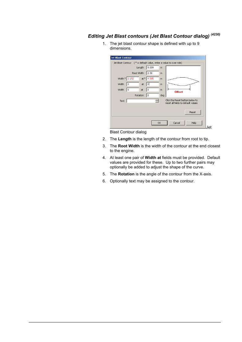
Editing Jet Blast contours (Jet Blast Contour dialog) (4230)
1. The jet blast contour shape is defined with up to 9 dimensions.
Jet Blast Contour dialog
2. The Length is the length of the contour from root to tip.
3. The Root Width is the width of the contour at the end closest to the engine.
4. At least one pair of Width at fields must be provided. Default values are provided for these. Up to two further pairs may optionally be added to adjust the shape of the curve.
5. The Rotation is the angle of the contour from the X-axis.
6. Optionally text may be assigned to the contour.
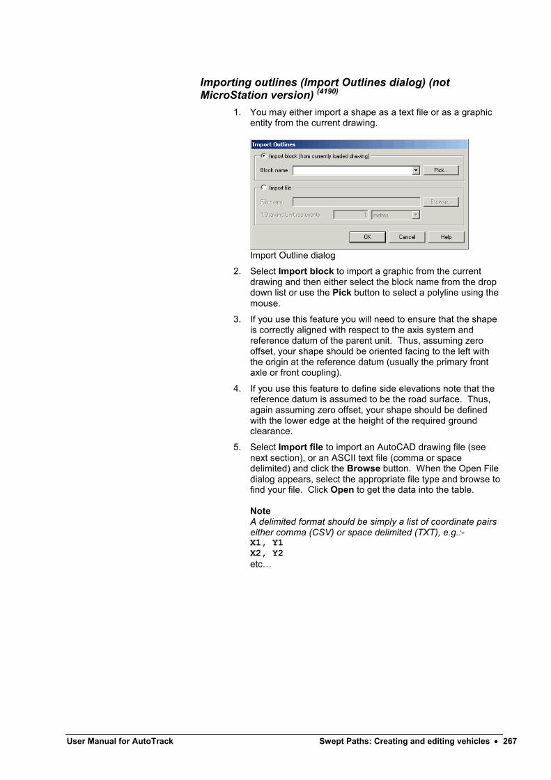
User Manual for AutoTrack Swept Paths: Creating and editing vehicles 267
Importing outlines (Import Outlines dialog) (not MicroStation version) (4190)
1. You may either import a shape as a text file or as a graphic entity from the current drawing.
Import Outline dialog
2. Select Import block to import a graphic from the current drawing and then either select the block name from the drop down list or use the Pick button to select a polyline using the mouse.
3. If you use this feature you will need to ensure that the shape is correctly aligned with respect to the axis system and reference datum of the parent unit. Thus, assuming zero offset, your shape should be oriented facing to the left with the origin at the reference datum (usually the primary front axle or front coupling).
4. If you use this feature to define side elevations note that the reference datum is assumed to be the road surface. Thus, again assuming zero offset, your shape should be defined with the lower edge at the height of the required ground clearance.
5. Select Import file to import an AutoCAD drawing file (see next section), or an ASCII text file (comma or space delimited) and click the Browse button. When the Open File dialog appears, select the appropriate file type and browse to find your file. Click Open to get the data into the table.
NoteA delimited format should be simply a list of coordinate pairs either comma (CSV) or space delimited (TXT), e.g.:-X1, Y1X2, Y2etc…

Importing AutoCAD drawing files
NoteThis feature is not available in the MicroStation version.
1. The facility to import outline data from drawing file allows you to import data for both plan view and side elevation (and any other outline types) in one operation. However, to ensure that the right elements go in the right outlines you must follow a layering convention.
2. The layer naming convention is as follows:-
{Outline Type}{Shape Group}
where {Outline Type} is one of the following:-
BODYOUTLINEPLANBODYDETAILPLANLOADOUTLINEPLANPANTOGRAPHJETEXHAUSTTEMPERATURE (or JETTEMP)JETEXHAUSTVELOCITY (or JETVEL)FIELDOFVISIONNOISESERVICINGBODYOUTLINESIDEUSERDEFINED1USERDEFINED2USERDEFINED3
and {Shape Group} is entirely at your discretion.
3. AutoTrack strips off any outline type prefixes that it recognises from the list above and uses the remainder as the name of the shape group. If there is no text remaining after the prefix has been removed AutoTrack supplies a default name for the shape group.
Example 1All entities on layer BODYOUTLINESIDEWINGMIRRORS in the imported drawing will be placed in the outline type Body outline (side) in a shape group called WingMirrors.
Example 2All entities on layer BODYOUTLINEPLAN in the imported drawing will be placed in the outline type Body outline (plan) in a default shape group called Body.
4. Draw a circle on layer UxORIGINPLAN and UxORIGINSIDEto specify an offset unit origin in plan and side views respectively where x represents the unit number. Thus the centre of a circle drawn on layer U1ORIGINSIDE is assumed to be the origin of the side view of unit 1.

User Manual for AutoTrack Swept Paths: Creating and editing vehicles 269
Unit Details: Couplings (4140)
1. Click on the Couplings tab.
Unit Details dialog: Couplings
2. Tick Front Coupling and / or Rear Coupling to include front and rear couplings respectively.
3. The Type of coupling dictates what other units can be connected to this unit, i.e. the coupling types must match. The exception is that any coupling type can be linked to a generic coupling. Coupling type Active Steerable Coupling allows users to model vehicles with no conventional steered wheels but instead a articulation point whose angle is controlled by the driver, e.g. by hydraulic rams. A unit may only have one coupling of this type and it is always the primary steering.
4. The Capability of the coupling specifies whether it can tow other units, be towed or both.
5. The position of the coupling is defined by the Coupling offset which is measured relative to the datum point.
6. The Coupling height is used for vertical clearance analysis and defaults to a proportion of the wheel diameter. Enter an accurate figure if you have one.
7. The Maximum horizontal angle is the maximum possible articulation angle between the two connected units in the horizontal plane. Note that when this unit is coupled to another the articulation angle specified in the vehicle details form takes precedence if it is lower. Thus, a vehicle uses the lower of the articulation angle defined in the vehicle details and these values.
8. The Maximum vertical angle is the maximum possible articulation angle between the two connected units in the vertical plane and is used for vertical clearance analysis.
9. Tick Assume coupling height matches rear coupling on previous unit if the front coupling is able to adjust to suit the height of the coupling on the towing unit.

Units Details: Doors (Aircraft only) (4125)
1. Click on the Doors tab.
Unit Details dialog: Doors
89. The doors are grouped into Upper Deck Passenger doors, Passenger doors, Cargo doors and Service doors.
90. To add a door move the cursor over the type you wish to add and click New.
91. Enter a Name for the door. The convention for passenger doors is to number them from front to back and prefixed with an ‘L’ for port (left) doors and an ‘R’ for starboard (right) doors. So port doors doors would be numbered L1, L2…..Ln.
92. Enter the X Offset & Y Offset of the door relative to the Reference Datum. X ordinates increase towards the back of the aircraft and the Y ordinates are positive to the right of the centreline and negative to the left.
93. Enter a Bearing for the door in degrees relative to the spine of the aircraft. Zero is due East.
94. To delete a door, highlight it and click Delete.
95. If you add a door to the wrong type, simply select the correct Type from the drop down list and the door will move.
Multiple heights
96. To add a copy of a door at a different height, highlight the door and click New.
97. Enter the Height of the door. All the other details will be copied automatically from the parent.
98. Finally, to omit selected door heights from boarding bridge slope calculations simply tick Ignore in slope calculations.
99. To delete a door height, highlight it and click Delete.

User Manual for AutoTrack Swept Paths: Creating and editing vehicles 271
Unit Details: Servicing (Aircraft only) (4125)
1. Click on the Servicing tab.
Unit Details: Servicing
2. The servicing is divided into Servicing Points and Servicing Vehicles and then further into each type of service .
3. To add a service point or vehicle highlight the type you wish to add and click New.
4. Enter a Name for the service point or vehicle.
5. Enter the X Offset & Y Offset of the service point or the front axle of the service vehicle relative to the Reference Datum. X ordinates increase towards the back of the aircraft and the Y ordinates are positive to the right of the centreline and negative to the left.
6. Enter a Bearing for the service point or vehicle in degrees relative to the spine of the aircraft. Zero is due East.
7. To delete a service point or vehicle, highlight it and click Delete.
8. If you add a service point or vehicle to the wrong type, simply select the correct Type from the drop down list and the service will move. It is not possible to move an entry from service points to vehicles or vice versa.
Multiple heights
9. To add a copy of a service point at a different height, highlight the service point and click New.
10. Enter the Height of the service point. All the other details will be copied automatically from the parent.
11. To delete a service point height, highlight it and click Delete.


User Manual for AutoTrack Parking: Creating and editing parking areas 273
Parking: Creating and editing parking areas
AutoTrack defines a parking area as a collection of parking rows each of which consists of individual bays. Each row is created in accordance with a standard. In most cases rows within a parking area use the same basic standard.
Placing rows of baysA row of bays is considered to be a single or double sided row of bays with any number of bends. All the bays on each side of a double row must have the same properties but they may differ from those of the other side. Rows may be placed freehand or parallel to other rows or objects.
To place a row of bays freehand
Place Row of Bays button
1. Select Place Row of Bays from the AutoTrack, Parking Layout menu or click the Place Row of Bays button on the Parking Layout toolbar.
2. If this is the first row placed in the current drawing, and you do not have a default standard set, the Parking Standard Explorer will appear for you to select the required standard (see Viewing a standard in a parking standard file or the pool (Parking Standard Explorer dialog)
(4400). If you do not have a
default standard set you may then be offered the chance to set it as your default (see Default Parking Standard dialog (4690)
). Finally, you will be asked to give the standard a unique name for easy reference in the current drawing (see Unique parking standard names).
3. The Row Properties dialog will appear non-modally, i.e. you can still access the main CAD window without closing the dialog first.
4. Set the row properties. Refer to Editing rows (Parking Row Properties dialog) for more details of this process.
5. Move the cursor to where you want the row baseline to start and left click to confirm. NoteYou may use snap to help you locate the precise start position.

6. Move the cursor to end of the row and left click to confirm.
7. Repeat this process, placing a point at each vertex or bend on the row.
8. When you have placed the last point right click to exit.
9. Finally you should select which side you want bays, either left, right or both. The red arrow that is displayed halfway along each row segment shows the current setting. Move the cursor to the left of the row to select bays only on the left, to the right to select bays only on the right or over the row baseline to select bays on both sides.
NoteTo disable the row side selection while the Parking Row Properties dialog is displayed untick Skip row side selection before placing the row.
To place a parallel row of bays
Place Parallel Row of Bays button
1. You can place rows of bays parallel to existing rows using the Place Parallel Row tool. Rows placed in this way are automatically extended or shortened according to the angles of the end islands, which themselves reflect the angle of the access road.
2. Select Place Parallel Row of Bays from the AutoTrack, Parking Layout menu or click the Place Parallel Row of Bays button on the Parking Layout toolbar. The Parking Row Properties dialog will appear non-modally, i.e. in such a way that you can still access the CAD window without closing the dialog first.
3. If this is the first row placed in the current drawing, and you do not have a default standard set, the Parking Standard Explorer will appear for you to select the required standard (see Viewing a standard in a parking standard file or the pool (Parking Standard Explorer dialog)
(4400). If you do not have a
default standard set you may then be offered the chance to set it as your default (see Default Parking Standard dialog (4690)
). Finally, you will be asked to give the standard a unique name for easy reference in the current drawing (see Unique parking standard names).
4. Set the properties of the parallel row. Refer to Editing rows (Parking Row Properties dialog) for more details of this process.
5. Select the row or line to which the new row will be parallel. The new row will appear and move as you move the cursor.
6. The dashed line from the end of the existing row to the cursor represents the distance of the baseline of the new row from the baseline of the existing row. Move the cursor until the row is positioned as you want it and then left click to confirm.
NoteThe row cannot be placed closer to the existing row or line than the minimum clearance zone allowed by the standard.
7. Finally you should select which side you want bays, either left, right or both. The red arrow that is displayed halfway
User Manual for AutoTrack Parking: Creating and editing parking areas 275
along each row segment shows the current setting. Move the cursor to the left of the row to select bays only on the left, to the right to select bays only on the right or over the row baseline to select bays on both sides.
NoteTo disable the graphical row side selection tick Skip row side selection on the Parking Row Properties dialog before placing the row.Tick Always skip row side selection if you want this feature disabled until further notice.
Unique parking standard names (Parking Standard Name dialog)
In order to make it easier to identify standards, and the parking bays that use them, we recommend that each standard used has a unique name. Therefore, when you place a new row (either freehand or parallel), that uses a standard not previously used within the current drawing, the Parking Standard Name dialog will appear offering a unique name of the form “Area n based upon {Parking Standard}”. You may edit this name but it must be unique. If you cancel the Parking Standard Name dialog the default name that was initially offered will be used.
To subsequently change the name of a standard, open the Parking Standard Explorer, select the required standard, right click and select Edit. Now you can change the name. See also To edit a parking standard.
Placing access roads (4430)
Access roads can be placed cutting through existing parking rows. These roads may be at any angle and may cut through as many parking rows as you wish.
To place an access road freehand
Place Access Road button
1. Select Place access road from the AutoTrack, Parking Layout menu, click on the Place access road button on the AutoTrack Parking Layout toolbar or type ATRAPLACEACCESSROAD on the command line.
2. The access road is defined by the left kerb, the right kerb or the centreline. Use the mouse to pick the start of the access road followed by the end. Note that the points you pick are only used for alignment purposes and their locations are otherwise unimportant. The Access Road Properties dialog will appear.

Access Road Properties dialog
3. The width of the road may either be determined from a standard or entered explicitly.
4. Select the Standard, Service type and Flow type and the Width from standard will be displayed. If you want to over-ride this value tick Custom width and enter the required width.
5. Set the Line alignment according to the alignment points you picked.
6. Click OK to confirm. AutoTrack will place the access road trimming any parking rows that your alignment crosses and calculating new end islands where necessary.
To place an access road on a line
Place Access Road on Line button
1. Select Place access road on line from the AutoTrack, Parking Layout menu, click on the Place access road on line button on the AutoTrack Parking Layout toolbar or type ATRACREATEACCESSROADFROMLINE on the command line.
2. Select a line representing the alignment of the left kerb, the right kerb or the centreline. The Access Road Properties dialog will appear.
Access Road Properties dialog
3. The width of the road may either be determined from a standard or entered explicitly.
4. Select the Standard, Service type and Flow type and the Width from standard will be displayed. If you want to over-ride this value tick Custom width and enter the required width.
5. Set the Line alignment according to the alignment points you picked. Note that the access road will be drawn from start to finish of the line that you picked so if this line represents a kerb you should make sure you know which end is the start. If you get it wrong then use Undo and rerun the

User Manual for AutoTrack Parking: Creating and editing parking areas 277
command specifying the opposite kerb.
6. Click OK to confirm. AutoTrack will place the access road trimming any parking rows that your alignment crosses and calculating new end islands where necessary.
Parking Report (4410)
The Parking Report is a dynamically updated bay count by any or all of the following:- parking standard, bay style, service type, vehicle class and / or parking zone.
To display the parking report
Parking Report button
1. Select Parking Report from the AutoTrack, Parking Layout menu, click the Parking Report button on the AutoTrack Parking Layout toolbar or type ATRAPARKINGREPORT on the command line. The Parking Report dialog will appear.
Parking Report dialog
2. Click Close when you no longer need it.
To customise the parking report
1. Click the Customise button on the Parking Report dialog. The Customise Parking Report dialog will appear.
Customise Parking Report dialog
2. Either select Show all columns or select Show selected columns and then the specific criteria you wish to report by. The Parking Report will change when you click OK.

To export a parking report
1. Click the Export button on the Parking Report dialog. A Save As dialog will appear.
2. Select the type of delimited file you wish to save from the Save as type drop down list.
3. Browse to the directory in which you wish to save the file.
4. Name the file without the extension and click Save.
5. The saved file may be read into Excel or any other program that supports comma or tab delimited files.
Editing rows (Parking Row Properties dialog) (4450)
Parking rows may comprise back to back bays or a single row of bays accessible from one or both sides. Back to back bays may differ in size, style and angle. Twin rows and single rows with single access may optionally have a kerb side access footpath. Dual access single rows of bays cannot have a footpath. If you need to have varying bay styles within a row then you should set the row style to the predominant style on each side and use the bay editing tool to change the style of those that differ.
To edit a parking row
Edit Parking Row button
1. Select Edit Parking Row from the AutoTrack, Parking Layout menu or click the Edit Parking Row button on the AutoTrack Parking Layout toolbar. The Parking Row Properties dialog will appear.

User Manual for AutoTrack Parking: Creating and editing parking areas 279
Parking Row Properties dialog
2. The bay alignment and end detail settings define the type of parking and in some cases restrict the bays to single or double row. If a double row is selected each side may have different properties.
3. The vehicle Flow direction in conjunction with the Bay angle determines how close the row can be placed to other rows or obstacles.
4. The Vehicle class and Vehicle type determine the basic size of the bay. However, the basic dimensions are often modified by the Bay style, so for example a disabled bay is generally wider than a standard bay.
5. The Zone name merely provides a means to divide a parking area into areas or zones. The Parking report can be set to report by zone name.
6. If you want the same bay angles on each side of a double row tick Lock angles.
7. Set the Start No. for each side to force a bay numbering sequence.
8. Each row may have islands and / or footpaths. Tick Footpath and enter a Width to specify a footpath running along the baseline, i.e. between the two sides on a double row or ‘behind’ a single row.

9. Tick Start island or End island to add islands at the start or end of the row. If you want a footpath to continue through the island tick Has footpath.
10. Tick Bend islands to add islands at every bend in the row. If you want a footpath to continue over the bend islands tick Have footpaths.
Editing individual bays (Parking Bay Properties dialog) (4440)
Individual parking bays within a row may vary from the default bay type for the row. However, every bay must be of a defined type for reporting purposes. Thus, for example, if you wanted one bay within a row to have a wheel stop you would first have to define that bay type and then set the bay to that type.
To edit a parking bay
Edit Parking Bay button
1. Select Edit Parking Bay from the AutoTrack, Parking Layout menu or click the Edit Parking Bay button on the AutoTrack Parking Layout toolbar. Select the row you want to edit. Grips will appear in each bay and the Parking Bay Properties dialog will appear.
Parking Bay Properties dialog
2. As you move the cursor over each bay the properties dialog updates to show the bay type. The other fields merely show what features comprise the selected bay type. All values will be displayed as read-only, i.e. non-editable.
3. As soon as you select a bay the Bay type drop down list box should become active, i.e. editable. If you select a different bay type the other fields will change to reflect the settings for the new type. The underlying bay type defined for the row is shown as (Default).
Note
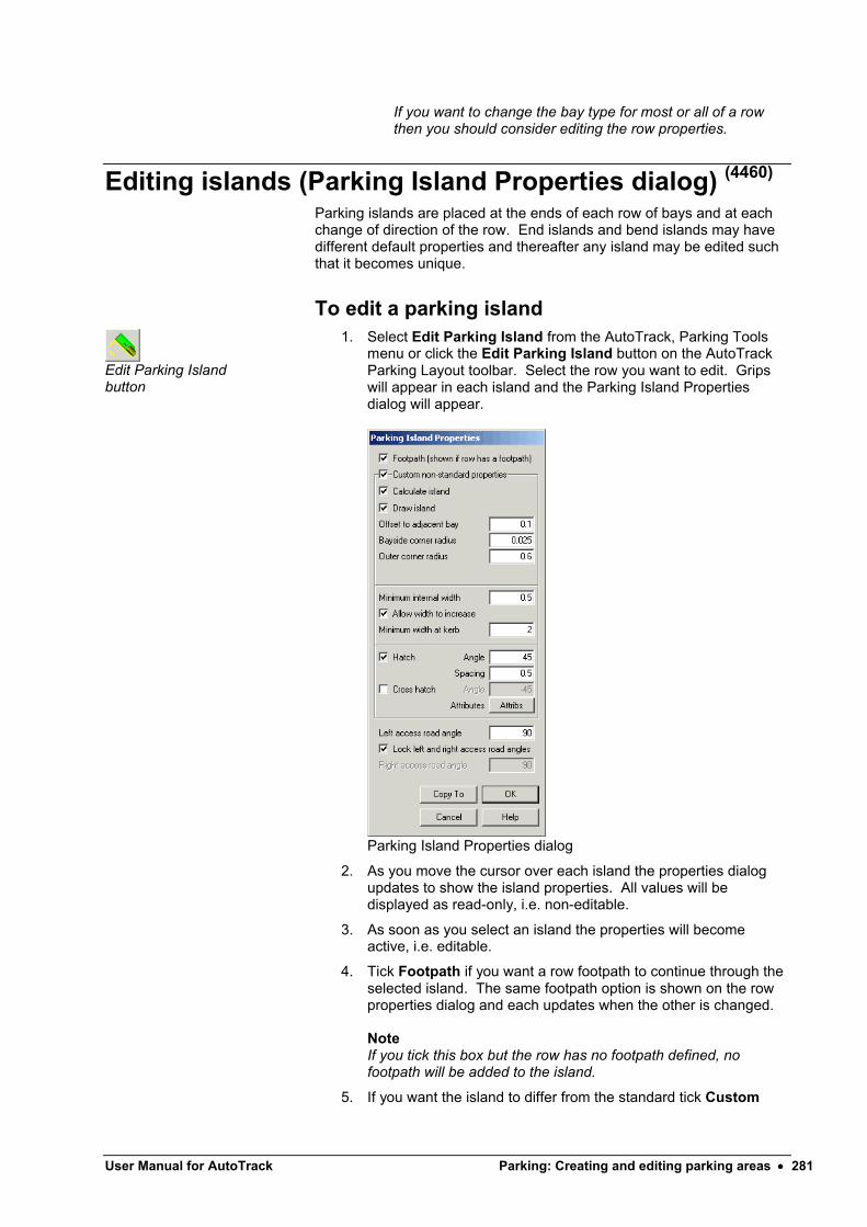
User Manual for AutoTrack Parking: Creating and editing parking areas 281
If you want to change the bay type for most or all of a row then you should consider editing the row properties.
Editing islands (Parking Island Properties dialog) (4460)
Parking islands are placed at the ends of each row of bays and at each change of direction of the row. End islands and bend islands may have different default properties and thereafter any island may be edited such that it becomes unique.
To edit a parking island
Edit Parking Islandbutton
1. Select Edit Parking Island from the AutoTrack, Parking Toolsmenu or click the Edit Parking Island button on the AutoTrack Parking Layout toolbar. Select the row you want to edit. Grips will appear in each island and the Parking Island Propertiesdialog will appear.
Parking Island Properties dialog
2. As you move the cursor over each island the properties dialog updates to show the island properties. All values will be displayed as read-only, i.e. non-editable.
3. As soon as you select an island the properties will become active, i.e. editable.
4. Tick Footpath if you want a row footpath to continue through the selected island. The same footpath option is shown on the row properties dialog and each updates when the other is changed.
NoteIf you tick this box but the row has no footpath defined, no footpath will be added to the island.
5. If you want the island to differ from the standard tick Custom

non-standard properties and change appropriate values.
6. The angles of ends of the start and end islands may be adjusted. This is often useful if an access road passes the end of the row. You can also edit the left side of the island separately from the right side if necessary. If the end of the island is angled uniformly across the width tick Lock left and right access road angles, and enter just the Left access road angle. If the left and right angles vary untick this box and additionally enter the Right access road angle.
Editing parking row layout
To move a row of bays
Move Parking Row button
1. Select Move Parking Row from the AutoTrack, Parking Tools menu or click the Move Parking Row button on the AutoTrack Parking Tools toolbar.
2. Select the row you wish to move.
3. Select the base point for the move.
4. Select the new position for the base point. The row will be redrawn in the new location.
To rotate a row of bays
Rotate Parking Row button
1. Select Rotate Parking Row from the AutoTrack, Parking Tools menu or click the Rotate Parking Row button on the AutoTrack Parking Tools toolbar.
2. Select the row you wish to rotate.
3. Select the base point about which the row will be rotated.
4. Select the rotation angle. The row will be redrawn in the new location.
To copy a row of bays
Copy Parking Row button
1. Select Copy Parking Row from the AutoTrack, Parking Tools menu or click the Copy Parking Row button on the AutoTrack Parking Tools toolbar.
2. Select the row you wish to copy. A copy of the row will appear.
3. Place the new row as you wish.
To explode a row of bays
Explode Parking Row button
After a row of parking bays has been exploded it cannot be edited using AutoTrack parking tools. We therefore recommend that you do notexplode your parking data without first making a backup copy.
1. Select Explode Parking Row from the AutoTrack, Parking Tools menu or click the Explode Parking Row button on the AutoTrack Parking Tools toolbar.
2. Select the row you wish to explode. The row will be exploded into simpe drawing entities.

User Manual for AutoTrack Parking: Creating and editing parking areas 283
To delete a row of bays
Delete Parking Row button
1. Select Delete Parking Row from the AutoTrack, Parking Tools menu or click the Delete Parking Row button on the AutoTrack Parking Tools toolbar.
2. Select the row you wish to delete. The row will be deleted without further warning.
To join two rows of parking bays
Join Parking Row button
1. Select Join Parking Rows from the AutoTrack, Parking Tools menu or click the Join Parking Rows button on the AutoTrack Parking Tools toolbar.
2. Select the two rows you wish to join. The two rows will be extended or shortened, without changing the alignment of the rows, until they meet.
To extend a row of parking bays
Extend Parking Row button
1. Select Extend Parking Row from the AutoTrack, Parking Tools menu or click the Extend Parking Row button on the AutoTrack Parking Tools toolbar.
2. Select the row you wish to extend. An arrow will appear at the end of the row closest to the cursor. As you move the cursor closer to the other end it will move to that end.
3. Move the cursor until the arrow is at the end you wish to extend and left click.
4. Now as you move the cursor the row will lengthen and shorten until you left click again. Notice that you can use this comand to shorten a row beyond a bend.
To add a vertex to a row of parking bays
Add Parking Row Vertex button
1. Select Add Parking Row Vertex from the AutoTrack, Parking Tools menu or click the Add Parking Row Vertex button on the AutoTrack Parking Tools toolbar.
2. Select the row you wish to extend. An arrow will appear at the end of the row closest to the cursor. As you move the cursor closer to the other end it will move to that end.
3. Move the cursor until the arrow is at the end you wish to extend and left click.
4. Now as you move the cursor a new segment will be created from the end you selected.
To adjust a parking row
Adjust Parking Row button
This is really a multi-purpose command that is available in AutoCAD and SavoyCAD by simply selecting a row.
1. Select Adjust Parking Row from the AutoTrack, Parking Tools menu or click the Adjust Parking Row button on the AutoTrack Parking Tools toolbar.
2. Select the row that you wish to adjust.
3. Small squares or “grips” will appear at various locations along the row. Each may be used to adjust a different aspect of the row.
4. Select the single green grip to move the entire row.
5. Select the grip furthest from the end of the row to extend the row with a new segment. If you select the next grip in you can extend the row in line. Finally, select the grip exactly at the end of the row to move or extend the end of the row in any direction.
6. Select the outermost grips on the sides of the end islands to adjust the angle of that side of the end island. Use the next grip in to adjust both sides together.
7. At one end of the row there are grips beside each of the first bays. Use these to change the bay angle. Note that you can only set and angle defined in the selected standard.
8. Select the grip at each bend vertex to adjust the position of the bend.
9. Select the grips on the direction arrows to specify a different flow direction. To set the direction one way select the grip, move the cursor in the direction you want the flow and left click to confirm. To set two-way traffic, select the arrow, move the cursor alongside it and left clik to confirm.
User Manual for AutoTrack Parking: Creating and editing standards 285
Parking: Creating and editing standards
AutoTrack parking standards define the geometric rules for the layout of parking rows and bays.
AutoTrack parking standardsAll parking layouts are created in accordance with defined rules or standards.
A number of standards are provided with the program and these may be used as the basis for your own company standards. The standards are grouped by nationality so, for example, the UK parking standards are held within a file called UK_xxx.ATP, where xxx is the most recent version of AutoTrack that can read it, e.g. UK_890.ATP. Additional parking standards are available for different markets and can even be created by users themselves. However, to ensure that the details do not change arbitrarily, there are restrictions on who can edit them. These restrictions require that users identify themselves if they wish to access a standard to make changes. No password is needed simply to use a standard.
Access to parking standards
Access to parking standards is restricted using a username / password system such that before a standard file can be opened for editing they must enter his or her name and password. Only if the user is authorisedwill they be allowed to open the standard file. There are three levels of access:-
None
You may list the standards but cannot access the details. This is the status of any standards that have not been purchased.
Read Only
You may use the standard file but may not change them or add new standards. All standard files are initially opened Read Only.
Full Access
You may use, copy, edit, or create new standards and add or edit the users.
All Savoy parking standards are Read Only.
Refer to Viewing a standard in a parking standard file or the pool (Parking Standard Explorer dialog) and Creating a new parking standard file (Parking Standard File dialog) for details of how to open standards files and maintain users.
Access to parking standards in the Pool
Unlike vehicles, parking standards, once in the Pool, may be edited even if they have been used.
NoteIf you make a copy of a standard in the same standard file it’s name is prefixed with the words ‘Copy of’ to distinguish it from the original standard.
Viewing a standard in a parking standard file or the pool (Parking Standard Explorer dialog) (4400)
Parking Standards button
1. Select Parking Standard Explorer from the AutoTrack, Parking Layout menu or click the Parking Standard Explorer button on the AutoTrack Parking Layout toolbar. The Parking Standard Explorer will appear. For details of the standards see Viewing or editing parking standards.
Parking Standard Explorer dialog
2. If the standard that you require is not loaded then select Open Parking Standard from the File menu in the Parking Standards Explorer, browse to find the standards file and click Open. A new Parking Standards File icon will appear in the Parking Standards Explorer with the name of the standard file beside it.
3. Click on the + symbol to expand the standard file or the pool.
4. Standards may be listed under different groups. If they are then click the + symbol to expand the required group.
5. Highlight the required standard (indicated by a check list icon) and select Edit (or View if the standards file is locked) from the Edit menu. The Parking Standard dialog will appear.
6. If you wish to edit a Standard Group then highlight it and select Edit (or View if the standards file is locked) from the

User Manual for AutoTrack Parking: Creating and editing standards 287
Edit menu. The Parking Standard Group dialog will appear.
7. To create a new parking standard, highlight the parent file or group and select New Parking Standard from the File menu.
8. To print a standard highlight it and select Print from the File menu or click the Print button. For more details refer to ??.
Creating a new parking standard file (Parking Standard File dialog)
Parking Standards button
1. Select Parking Standards from the AutoTrack, Parking Layout menu or click the Parking Standards button on the AutoTrack Parking Layout toolbar. The Parking Standard Explorer dialog will appear.
2. Select New Parking Standard File from the File menu in the Parking Standard Explorer. The Parking Standard File dialog will appear.
Parking Standard File dialog
3. Click the appropriate tab to edit or view the settings.
4. Edit the data as required and click OK to confirm when you are satisfied. Click Cancel to abort all changes and close the dialog.
Parking Standard File: Parking Standard File
1. Click the Parking Standard File tab.
2. Give the standard file a meaningful Name.
3. The Version and Notes fields are provided for additional information and may be used at your discretion.
4. The File Name is read only and will be filled in when the file is saved.
Parking Standard File: Users

NoteYou may only add new users or edit existing users in standard files to which you have full access rights.
1. Click on the Users tab.
Parking Standard File: Users
2. On a new standard file all users have full access as indicated by the default entry in the Users table. At least one user in the table must have full access before you may downgrade the default Any User rights.
To add a new user
1. On the Parking Standard File dialog click New. The New User dialog will appear.
New User dialog
2. Enter the new User Name. Depending upon how you want to restrict access, this may be a specific person or a department name.
3. Enter the Password and then repeat it in the Validate Password field. This checks that you typed the password correctly. If you do not enter a password the named user will be able to unlock the standard file without typing a password.
4. Finally set the Access Level. We recommend that you add

User Manual for AutoTrack Parking: Creating and editing standards 289
any users that you want to have full access and then downgrade the default Any User to Read Only.
5. Even tighter restrictions can be placed by downgrading Any User to No Access and adding Read Only users as required. However, this may prove problematic in practice.
To edit an existing user (Maintain User dialog)
Note You may only add new users or edit existing users in libraries to which you have full access rights.
1. On the Parking Standard File dialog highlight the user that you wish to edit and click Edit. The Maintain User dialog will appear.
Maintain User dialog
2. Change the Password and / or set a new Access Level and click OK to confirm. If you do not enter a password the named user will be able to unlock the standard file without typing a password.
3. Click Cancel to abort any changes.
NoteYou cannot delete users; instead you must set their access level to None.
Saving a parking standard file
Parking Standards button
1. Select Parking Standards from the AutoTrack, Parking Layout menu or click the Parking Standards button on the AutoTrack Parking Layout toolbar. The Parking Standard Explorer will appear.
2. Highlight the standard that you want to save, right click and select Save Parking Standard File As from the drop down menu that appears. The Save Parking Standard File As dialog will appear.
3. Browse to the required storage directory, enter the filename and click Save.
4. If the standard file already has a name then you can use Save Parking Standard File.
Sharing a parking standard (Share Data dialog)
Vehicle Library button
1. Select Parking Standards from the AutoTrack, Parking Layout menu or click the Parking Standards button on the AutoTrack Parking Layout toolbar. The Parking Standard Explorer will appear.
2. Highlight the standard that you want to share, right click and select Share Data from the drop down menu that appears.
3. The Share Data dialog will appear.
Share Data dialog
4. Select who you want to share the standard with and click OK.
If you select With other users on this computer a copy will be placed in the public data directory on your computer.
If you select With other users on my network a copy will be placed in the shared data directory (if one is defined).
Copying standards and units using drag and dropParking standards are automatically copied to the Pool when they are used but you may wish to edit a standard before using it or indeed build your own parking standards.
To copy a parking standard to the pool, select it, drag it over the Pool symbol and drop it. If you wish to copy it to another standard you will need full access rights in the destination parking standard file. The cursor will change to a no entry symbol to indicate areas where you may not drop the standard.
You can also make copies of parking standards within parking standard files in the same way; in this case the name of the standard is prefixed with the words ‘Copy of ‘, to distinguish it from the original.
Unlocking a parking standard file (Unlock Parking Standard File dialog) (3555)
1. Highlight the parking standard file that you want to unlock, right click and select Unlock Parking Standard File from the drop down menu that appears. If a password has been set for the standard file, the Unlock Parking Standard File dialog will appear. Otherwise, the standard file will be unlocked and you should refer to step 3.
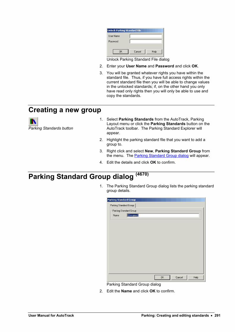
User Manual for AutoTrack Parking: Creating and editing standards 291
Unlock Parking Standard File dialog
2. Enter your User Name and Password and click OK.
3. You will be granted whatever rights you have within the standard file. Thus, if you have full access rights within the current standard file then you will be able to change values in the unlocked standards; if, on the other hand you only have read only rights then you will only be able to use and copy the standards.
Creating a new group
Parking Standards button
1. Select Parking Standards from the AutoTrack, Parking Layout menu or click the Parking Standards button on the AutoTrack toolbar. The Parking Standard Explorer will appear.
2. Highlight the parking standard file that you want to add a group to.
3. Right click and select New, Parking Standard Group from the menu. The Parking Standard Group dialog will appear.
4. Edit the details and click OK to confirm.
Parking Standard Group dialog (4670)
1. The Parking Standard Group dialog lists the parking standardgroup details.
Parking Standard Group dialog
2. Edit the Name and click OK to confirm.

Selecting a Parking Standard
To set a default parking standard
1. Highlight the parking standard that you want to set as your default and click the Make Default button.
2. The next time you place a parking bay or row this standard will be used.
Default Parking Standard dialog (4690)
1. AutoTrack allows you to define a default parking standard, i.e. a standard that will be used every time you place a parking bay unless you actively select an alternative. This can be very useful if you regularly use the same standard. If you select a standard to use and you do not have a default standard set the Default Parking Standard dialog will appear.
Default Parking Standard dialog
2. If you select Yes then this standard will be selected automatically next time you place a parking bay. If you select No then you will be asked this again the next time you select a standard in similar circumstances.
3. If you don’t want to be asked again then tick Don’t ask me this again.

User Manual for AutoTrack Parking: Creating and editing standards 293
Viewing or editing parking standardsParking standards supplied by Savoy can only be edited once they have been selected for a project. Then, any changes you make to the standard will affect not only new bays but also any bays that have already been placed. Once you have used a standard all bays placed will use that standard.
You may edit parking standards that you create. However, in order to prevent accidental changes, they will be locked when you close AutoTrack and you will need to unlock them to make any changes.
To edit a parking standard
Parking Standards button
1. Select Parking Standards from the AutoTrack, Parking Layout menu or click the Parking Standards button on the AutoTrack Parking Layout toolbar. The Parking StandardExplorer dialog will appear.
Parking Standard Explorer dialog
2. If the standard file that you require is not loaded then select Open Parking Standard from the File menu in the Parking Standard Explorer, browse to find the standard file and click Open. A new parking standard icon will appear in the Parking Standard Explorer with the name of the standard file beside it.
3. Click on the + symbol to expand the standard file or the pool.
4. Click the + symbol adjacent to the required group if necessary.
5. Highlight the required standard (indicated by a check sheet symbol dependant) and select Edit (or View if the Standard is locked) from the Edit menu. The Parking Standard dialog will appear.
6. If you wish to edit a parking standard group then highlight it and select Edit (or View if the standard file is locked) from the Edit menu in the Parking Standard Explorer. The Parking Standard Group dialog will appear.
7. To create a new parking standard highlight the parent file or group, right click and and select New Parking Standardfrom the menu that appears.
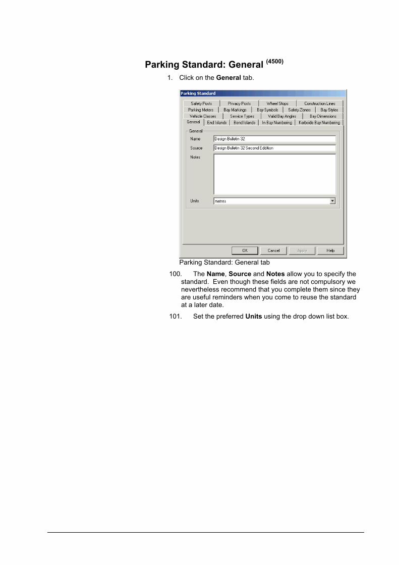
Parking Standard: General (4500)
1. Click on the General tab.
Parking Standard: General tab
100. The Name, Source and Notes allow you to specify the standard. Even though these fields are not compulsory we nevertheless recommend that you complete them since they are useful reminders when you come to reuse the standardat a later date.
101. Set the preferred Units using the drop down list box.

User Manual for AutoTrack Parking: Creating and editing standards 295
Parking Standard: End Islands (4480)
1. End islands are placed at the ends of a row of parking bays.
102. Click on the End Islands tab.
Parking Standard: End Islands tab
103. Set the Offset to adjacent bay to the distance from the start of the end island to the side marking of the last bay.
104. Set the Bayside corner radius to the radius of the corners of the island that meet the bay.
105. Set the Outer corner radius to the radius of the corners of the island that are adjacent to the access road.
106. Set the Minimum internal width to the minimum width of the island at any point.
107. Tick Allow width to increase to allow the island stretch sideways.
108. Set the Minimum width at kerb to the minimum width of the island where it meets the kerb, i.e. on the baseline.
109. Tick Draw island to show the island. Note that even if this option is not ticked the island is still calculated and the space allocated.
110. Tick Hatch and / or Cross hatch to display a hatch pattern within the island. You may adjust the hatch Spacingand Angle.
111. Click the Attributes button to modify the Colour, Line type and Line weight in the Attributes dialog.

Parking Standard: Bend Islands (4470)
1. Bend islands are placed at changes in direction of a row of parking bays.
112. Click on the Bend Islands tab.
Parking Standard: Bend Islands tab
113. Set the Offset to adjacent bays to the distance from the start of the island to the side marking of the adjacent bays.
114. Set the Bayside corner radius to the radius of the corners of the island that meet the bay.
115. Set the Outer corner radius to the radius of the corners of the island that are adjacent to the access road.
116. The Minimum internal width is the minimum width of the island at any point.
117. Tick Allow width to increase to allow the island stretch sideways.
118. Set the Minimum width at kerb to the minimum width of the island where it meets the kerb, i.e. on the baseline.
119. Tick Draw island to show the island. Note that even if this option is not ticked the island is still calculated and the space allocated.
120. Tick Hatch and / or Cross hatch to display a hatch pattern within the island. You may adjust the hatch Spacingand Angle.
121. Click the Attributes button to modify the Colour, Line type and Line weight in the Attributes dialog.

User Manual for AutoTrack Parking: Creating and editing standards 297
Parking Standard: In Bay Numbering (4510)
1. In bay numbering is when bay numbers are painted within the area of the parking bay.
122. Click on the In Bay Numbering tab.
Parking Standard: In Bay Numbering tab
123. Set the Width of number to the preferred width of each character.
124. Set the Height of number to the preferred height of each character.
125. Tick Roman numerals to display the number in roman numeral format.
126. Tick Number first bay, Number last bay and / or Number intermediate bays to specify which bays should be numbered in the bay.
127. Set the Offset from end of bay to the distance from the end of the bay to the centre of the number.
128. Tick Place in centre to place the number centrally in the bay.
129. Tick Place number at kerb end of bay to offset the number from the kerb end of the bay instead of from the entrance end.
130. Set the Rotation to the required orientation for the number. If set to zero the number will face the driver entering the bay.
131. Click the Line Style button to modify the Colour, Line type and Line weight in the Attributes dialog.

Parking Standard: Kerbside Bay Numbering (4520)
1. Kerbside bay numbering is when bay numbers are painted either beside or at the end of the parking bays.
132. Click on the Kerbside Bay Numbering tab.
Parking Standard: Kerbisde Numbering tab
133. Set the Width of number to the preferred width of each character.
134. Set the Height of number to the preferred height of each character.
135. Tick Roman numerals to display the number in roman numeral format.
136. Tick Number first bay, Number last bay and / or Number intermediate bays to specify which bays should be numbered in the bay.
137. Set the Offset from end of bay to the distance from the end of the bay to the centre of the number.
138. Tick Offset fromkerb to measure the offset from the kerb rather than the end of the bay.
139. Set the Offset from side of bay to the distance from the drivers side line to the centre of the number.
140. Set the Rotation to the required orientation for the number. If set to zero the number will face the driver entering the bay.
141. Click the Line Style button to modify the Colour, Line type and Line weight in the Attributes dialog.

User Manual for AutoTrack Parking: Creating and editing standards 299
Parking Standard: Vehicle Classes (4640)
1. Vehicles that might use the parking area are split into groups known as vehicle classes. Typically each vehicle class has different parking requirements.
142. Click on the Vehicle Classes tab.
Parking Standard: Vehicle Classes tab
143. The defined vehicle classes are listed in the large window. As you move the cursor between the entries the edit boxes beneath show the values associated with the selected vehicle class.
144. Set the Vehicle class to the name of the class.
145. Set the Default bay length to the length of bay required for this class of vehicle.
146. Set the Default bay width to the width of bay required for this class of vehicle.
147. Click New to add a new vehicle class. Highlight a vehicle class and click Duplicate to create a copy of an existing class or click Delete to delete the selected class.

Parking Standard: Service Types (4570)
1. Each parking area has particular access requirements which for ease of reference are called service types.
148. Click on the Service Types tab.
Parking Standard: Service Types tab
149. The defined service types are listed in the large window. As you move the cursor between the entries the edit boxes beneath show the values associated with the selected service type. Note that the aisle widths listed here are the base values used to create the bay dimensions table.
150. Set the One way aisle width to the width of aisle required for one way vehicle circulation past the entrances to the bays.
151. Set the Two way aisle width to the width of aisle required for two way vehicle circulation past the entrances to the bays.
152. Set the One way access road width to the minimum width of road required for one way circulation in the access roads feeding the row aisles.
153. Set the Two way access road width to the minimum width of road required for two way circulation in the access roads feeding the row aisles.
154. Set the Footpath width to the preferred width of footpath between back to back parking bays.
155. Click New to add a new service type. Highlight a service type and click Duplicate to create a copy of an existing type or click Delete to delete the selected type.

User Manual for AutoTrack Parking: Creating and editing standards 301
Parking Standard: Valid Bay Angles (4630)
1. In order to create an optimum parking layout it is normally desirable to limit the angles at which vehicles may park.
156. Click on the Valid Bay Angles tab.
Parking Standard: Valid Bay Angles tab
157. Valid angles are listed in the large window.
158. To edit an angle highlight it in the list and edit the value in the Bay angle edit box beneath.
159. Click New to add a new angle.
160. Highlight an angle and click Delete to remove an angle from the list.
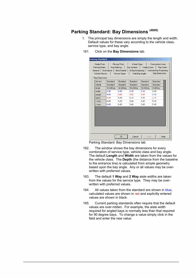
Parking Standard: Bay Dimensions (4600)
1. The principal bay dimensions are simply the length and width. Default values for these vary according to the vehicle class, service type, and bay angle.
161. Click on the Bay Dimensions tab.
Parking Standard: Bay Dimensions tab
162. The window shows the bay dimensions for every combination of service type, vehicle class and bay angle. The default Length and Width are taken from the values for the vehicle class. The Depth (the distance from the baseline to the entrance line) is calculated from simple geometry based upon the bay angle. Any or all values may be over-written with preferred values.
163. The default 1 Way and 2 Way aisle widths are taken from the values for the service type. They may be over-written with preferred values.
164. All values taken from the standard are shown in blue, calculated values are shown in red and explicitly entered values are shown in black.
165. Current parking standards often require that the default values are over-ridden. For example, the aisle width required for angled bays is normally less than that required for 90 degree bays. To change a value simply click in the field and enter the new value.
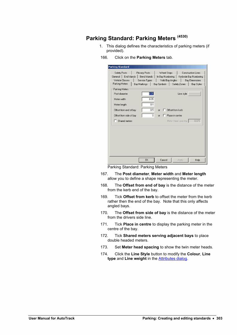
User Manual for AutoTrack Parking: Creating and editing standards 303
Parking Standard: Parking Meters (4530)
1. This dialog defines the characteristics of parking meters (if provided).
166. Click on the Parking Meters tab.
Parking Standard: Parking Meters
167. The Post diameter, Meter width and Meter lengthallow you to define a shape representing the meter.
168. The Offset from end of bay is the distance of the meter from the kerb end of the bay.
169. Tick Offset from kerb to offset the meter from the kerb rather then the end of the bay. Note that this only affects angled bays.
170. The Offset from side of bay is the distance of the meter from the drivers side line.
171. Tick Place in centre to display the parking meter in the centre of the bay.
172. Tick Shared meters serving adjacent bays to place double headed meters.
173. Set Meter head spacing to show the twin meter heads.
174. Click the Line Style button to modify the Colour, Line type and Line weight in the Attributes dialog.
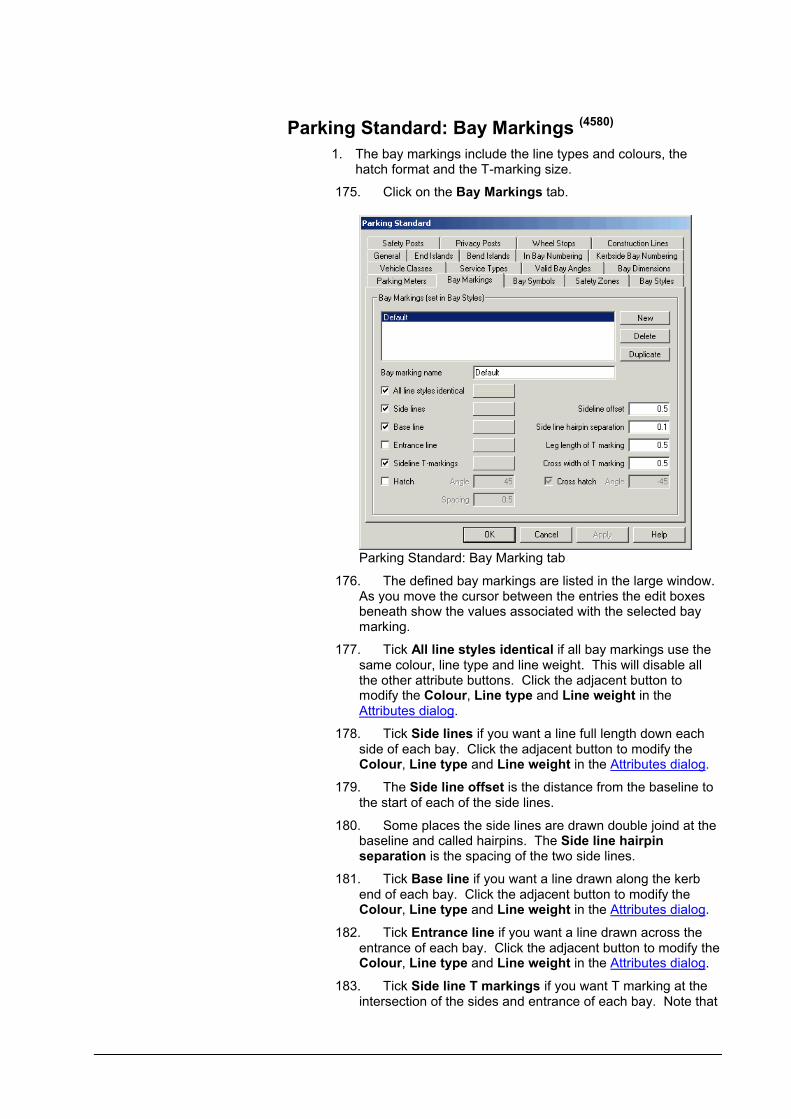
Parking Standard: Bay Markings (4580)
1. The bay markings include the line types and colours, the hatch format and the T-marking size.
175. Click on the Bay Markings tab.
Parking Standard: Bay Marking tab
176. The defined bay markings are listed in the large window. As you move the cursor between the entries the edit boxes beneath show the values associated with the selected bay marking.
177. Tick All line styles identical if all bay markings use the same colour, line type and line weight. This will disable all the other attribute buttons. Click the adjacent button to modify the Colour, Line type and Line weight in the Attributes dialog.
178. Tick Side lines if you want a line full length down each side of each bay. Click the adjacent button to modify the Colour, Line type and Line weight in the Attributes dialog.
179. The Side line offset is the distance from the baseline to the start of each of the side lines.
180. Some places the side lines are drawn double joind at the baseline and called hairpins. The Side line hairpin separation is the spacing of the two side lines.
181. Tick Base line if you want a line drawn along the kerb end of each bay. Click the adjacent button to modify the Colour, Line type and Line weight in the Attributes dialog.
182. Tick Entrance line if you want a line drawn across the entrance of each bay. Click the adjacent button to modify the Colour, Line type and Line weight in the Attributes dialog.
183. Tick Side line T markings if you want T marking at the intersection of the sides and entrance of each bay. Note that

User Manual for AutoTrack Parking: Creating and editing standards 305
this may be in addition to, or instead of, side and / or entrance lines. Click the adjacent button to modify the Colour, Line type and Line weight in the Attributes dialog.
184. The Leg length of T marking is the length of the vertical of the T marking.
185. The Cross width of T marking is the width of the horizontal of the T marking.
186. Tick Hatch and / or Cross hatch to display a hatch pattern. You may adjust the hatch Spacing and Angle.
187. Click New to add a new bay marking. Highlight a bay marking and click Duplicate to create a copy of an existing bay marking or click Delete to delete the selected marking.

Parking Standard: Bay Symbols (4620)
1. This dialog allows you to define bay symbols and includes type (e.g. disabled markings), size, colour and location. It also caters for additional text.
188. Click on the Bay Symbols tab.
Parking Standard: Bay Symbols tab
189. The defined bay symbols are listed in the large window. As you move the cursor between the entries the edit boxes beneath show the values associated with the selected bay symbol.
190. The Symbol is the icon that will be drawn in the bay. Click the adjacent button to modify the Colour, Line typeand Line weight in the Attributes dialog.
191. The Symbol Offset is the distance from the entrance line to the centre of the symbol.
192. Tick Place in centre of bay to place the symbol halfway between the entrance line and the baseline.
193. The Symbol height is the overall height of the selected symbol. The symbol proportions are contrained so there is no need to enter a width.
194. You may place a text instead of, or as well as, a symbol. The Text is the text that will be displayed in the bay. Click the adjacent button to modify the Colour, Line type and Line weight in the Attributes dialog.
195. The Text Offset is the distance from the entrance line to the centre of the text.
196. Tick Place in centre of bay to place the text halfway between the entrance line and the baseline.
197. The Text height is the text character height.

User Manual for AutoTrack Parking: Creating and editing standards 307
198. The Width is the overall width of the text string, not the individual character width.
199. The Text Rotation is the orientation of the text. If set to zero the text will face the driver entering the bay.
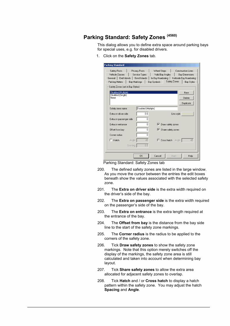
Parking Standard: Safety Zones (4560)
This dialog allows you to define extra space around parking bays for special uses, e.g. for disabled drivers.
1. Click on the Safety Zones tab.
Parking Standard: Safety Zones tab
200. The defined safety zones are listed in the large window. As you move the cursor between the entries the edit boxes beneath show the values associated with the selected safety zone.
201. The Extra on driver side is the extra width required on the driver’s side of the bay.
202. The Extra on passenger side is the extra width required on the passenger’s side of the bay.
203. The Extra on entrance is the extra length required at the entrance of the bay.
204. The Offset from bay is the distance from the bay side line to the start of the safety zone markings.
205. The Corner radius is the radius to be applied to the corners of the safety zone.
206. Tick Draw safety zones to show the safety zone markings. Note that this option merely switches off the display of the markings, the safety zone area is still calculated and taken into account when determining bay layout.
207. Tick Share safety zones to allow the extra area allocated for adjacent safety zones to overlap.
208. Tick Hatch and / or Cross hatch to display a hatch pattern within the safety zone. You may adjust the hatch Spacing and Angle.

User Manual for AutoTrack Parking: Creating and editing standards 309
209. Click the Line Style button to modify the Colour, Line type and Line weight in the Attributes dialog.
210. Click New to add a new safety zone. Highlight a safety zone and click Duplicate to create a copy of an existing safety zone or click Delete to delete the selected zone.
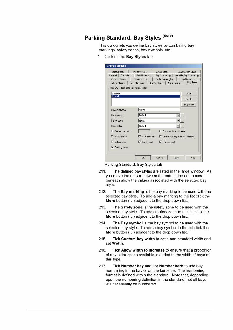
Parking Standard: Bay Styles (4610)
This dialog lets you define bay styles by combining bay markings, safety zones, bay symbols, etc.
1. Click on the Bay Styles tab.
Parking Standard: Bay Styles tab
211. The defined bay styles are listed in the large window. As you move the cursor between the entries the edit boxes beneath show the values associated with the selected bay style.
212. The Bay marking is the bay marking to be used with the selected bay style. To add a bay marking to the list click the More button (…) adjacent to the drop down list.
213. The Safety zone is the safety zone to be used with the selected bay style. To add a safety zone to the list click the More button (…) adjacent to the drop down list.
214. The Bay symbol is the bay symbol to be used with the selected bay style. To add a bay symbol to the list click the More button (…) adjacent to the drop down list.
215. Tick Custom bay width to set a non-standard width and set Width.
216. Tick Allow width to increase to ensure that a proportion of any extra space available is added to the width of bays of this type.
217. Tick Number bay and / or Number kerb to add bay numbering in the bay or on the kerbside. The numbering format is defined within the standard. Note that, depending upon the numbering definition in the standard, not all bays will necessarily be numbered.

User Manual for AutoTrack Parking: Creating and editing standards 311
218. Tick Wheel stop, Privacy post, Safety post and / or Parking meter to add these features to the selected bay type.

Parking Standard: Safety Posts (4550)
Safety posts are generally placed at the ends of bays and prevent vehicles from accidentally hitting pedestrians.
1. Click on the Safety Posts tab.
Parking Standard: Safety Posts tab
2. The Post diameter is the diameter of the safety post.
3. The Width is the width of the safety barrier, i.e. the distance measured in the direction of the bay width.
4. The Length is the length of the safety barrier, i.e. the distance measured in the direction of the bay length.
5. The Offset is the distance from the centre of the safety post to the end of the bay.
6. Tick Offset from kerb to measure the offset from the kerb instead of the end of the bay. Note this will only affect angled bays.
7. Click the Line Style button to modify the Colour, Line typeand Line weight in the Attributes dialog.

User Manual for AutoTrack Parking: Creating and editing standards 313
Parking Standard: Privacy Posts (4540)
Privacy posts are placed at the entrances to personal parking bays to prevent unauthorized use.
1. Click on the Privacy Posts tab.
Parking Standard: Privacy Posts tab
219. The Post diameter is the diameter of the privacy post.
220. The Width is the width of a privacy barrier, i.e. the distance measured in the direction of the bay width.
221. The Length is the length of a privacy barrier, i.e. the distance measured in the direction of the bay length.
222. The Offset is the distance from the centre of the privacy post to the end of the bay.
223. Tick Offset from kerb to measure the offset from the kerb instead of the end of the bay. Note this will only affect angled bays.
224. Click the Line Style button to modify the Colour, Line type and Line weight in the Attributes dialog.

Parking Standard: Wheel Stops (4650)
Wheel stops are placed a short distance back from the end of the bay and prevent vehicles from overhanging the end.
1. Click on the Wheel Stops tab.
Parking Standard: Wheel Stops tab
2. The Width of the wheel stop is measured in the direction of the length of the bay.
3. The Length of the wheel stop is measured in the direction of the width of the bay.
4. Tick Stretch to fill bay width to place wheel stops across the entire width of the bay.
5. Tick Shared wheel stops to place wheel stops on the dividing line between two adjacent bays. If you tick this option then you will no longer be able to place the wheel stop using Offset from side of bay or Place in centre of bay.
6. The Top width indent is the taper in the width of the wheel stop, e.g. if the base width is 0.3m and the width at the top is 0.2m then the top width indent is 0.05m.
7. The Top length indent is the taper in the length of the wheel stop, e.g. if the base length is 1.5m and the length at the top is 1.4m then the top length indent is 0.05m.
8. The Offset from end of bay is the distance from the centre of the wheel stop to the end of the bay.
9. The Offset from side of bay is the distance from the centre of the wheel stop to the bay side line on the driver’s side.
10. Tick Place in centre of bay to position the wheel stop in the middle of the bay width.
11. Click the Line Style button to modify the Colour, Line typeand Line weight in the Attributes dialog.
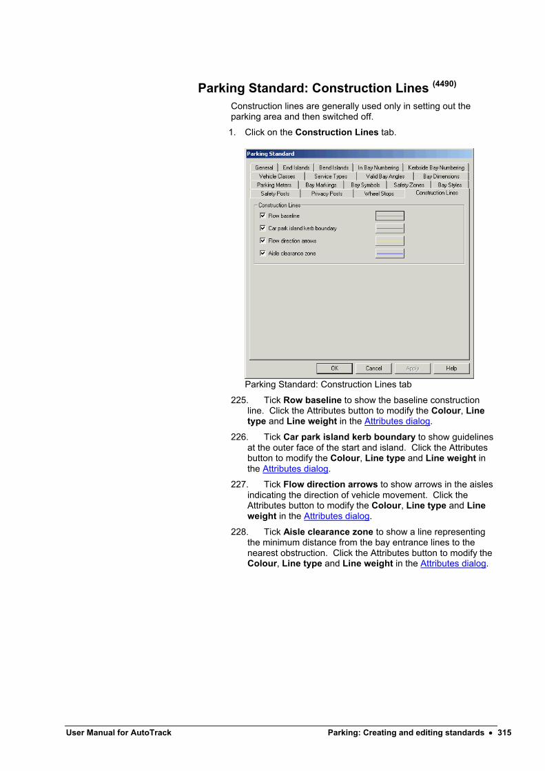
User Manual for AutoTrack Parking: Creating and editing standards 315
Parking Standard: Construction Lines (4490)
Construction lines are generally used only in setting out the parking area and then switched off.
1. Click on the Construction Lines tab.
Parking Standard: Construction Lines tab
225. Tick Row baseline to show the baseline construction line. Click the Attributes button to modify the Colour, Line type and Line weight in the Attributes dialog.
226. Tick Car park island kerb boundary to show guidelines at the outer face of the start and island. Click the Attributesbutton to modify the Colour, Line type and Line weight in the Attributes dialog.
227. Tick Flow direction arrows to show arrows in the aisles indicating the direction of vehicle movement. Click the Attributes button to modify the Colour, Line type and Line weight in the Attributes dialog.
228. Tick Aisle clearance zone to show a line representing the minimum distance from the bay entrance lines to the nearest obstruction. Click the Attributes button to modify the Colour, Line type and Line weight in the Attributes dialog.

Attributes dialog
Attributes dialog
1. Select the Colour from the drop down list of 254 pens. To set a custom colour select {custom} and click on the colour swatch.
2. Select the Line type from the drop down list. The line types listed are those currently available in your CAD system. If you wish to add a line type you should cancel this dialog and create the line type in your host CAD system.
3. Select the Line weight from the drop down list. Note that line weights are real world dimensions so if you select a line weight of 2mm the object will be drawn with 2mm thick lines.

User Manual for AutoTrack Review 317
Review
AutoTrack Review includes the tools you need to view, edit, assess and validate your AutoTrack projects.
If you only have the Review product then you will only be able to view data and not change it.
PropertiesThe Properties command lets you look at the details of any AutoTrack entity in your drawing.
Properties button
1. Select Properties from the AutoTrack drop down menu or click the Properties button on the AutoTrack Review toolbar. The Properties dialog appropriate to the entity you are editing will appear.
2. If you are editing a path then refer to Viewing the properties of a path (Path Properties dialog) for more details.
3. If you are editing a parking row then refer to Editing rows (Parking Row Properties dialog)
(4450)for more details.
Drawing Explorer (3300)
Sometimes you need to view or edit more than one path. For example, to apply the same colours and report settings to all paths. The Drawing Explorer allows you to edit all paths in all drawings.
Drawing Explorer button
1. Select Drawing Explorer from the AutoTrack drop down menu or click the Drawing Explorer button on the AutoTrack toolbar. The Drawing Explorer dialog will appear.

Drawing Explorer dialog
2. At the top of the window are the New Drawing Settings. This expands to display New Path Report Settings and New Path Settings. These are the default swept path settings for new drawings; i.e. the values stored in the settings files. The New Path Report Settings are used when you create a new report and the New Path Settings are used when you create a new path.
3. Underneath the New Drawing Settings are listed all the drawings that are currently open. Each one expands to display New Path Report Settings, New Path Settings and a list ofAutoTrack entities. The New Path Report Settings and New Path Settings are the defaults used when you create a new report or path in the current drawing.
4. To edit an entity, currently either a Path or a Parking Row, highlight it and click View or Edit. The properties dialog appropriate to the entity type will appear. Refer to Viewing the properties of a path (Path Properties dialog) or Editing rows (Parking Row Properties dialog)
(4450)for more details.
5. Each Path expands to display the Construction Lines and a list of Reports used by that path. This is the same list that you see when you edit a single path by clicking Properties, Reports. To view a report or construction line element highlight it and click View or Edit.
The following editing functionality is not available in the Review only product:-
6. To edit a report or construction line element highlight it and click Edit exactly as you do when you edit a single path using Properties.
7. To add a copy of a report, highlight it and click Duplicate. You can then use Edit to modify it.
8. To rename a report highlight the report and click Rename.
9. To add a new report based upon the new report settings for that drawing, highlight the report and click New.

User Manual for AutoTrack Review 319
10. To remove a report from the list, highlight it report and click Delete.
11. To apply the properties of a report element, a set of reports or a path to another like element, highlight the element you want to copy and click Select. Now go to the destination report element and click Replace. You can apply the properties to as many elements as you wish by highlighting them and clicking Replace or click Replace All to apply the properties to all the elements.
12. If the destination element is more senior in the hierarchy (a drawing contains paths and paths contain reports) then the properties of all child elements in the destination of the same type as the source element will be replaced with the source. This is best illustrated by a few examples:-
Example 1If you select a report and replace a different report, the properties of the replaced report will simply be changed to match the selected report, i.e. the sub-reports that are selected, the colours, etc.
Example 2If you select a report and replace a path, all reports in the replaced path will be removed and replaced by the selected report.
Example 3If you select a report and replace a drawing, all the reports associated with all the paths in the drawing (including the New Path Settings and the New Report Settings) will be removed and replaced by the selected report.
Example 4If you select a path and replace a drawing, all the properties of all the paths in the drawing (including the New Path Settings) will be replaced by those of the selected path.
13. If you want to add a report to another path or drawing, highlight the report you want to copy and click Select. Now highlight the destination path or drawing and click Insert. A copy of the selected report will be inserted into the path or into all paths in the drawing (including the New Path Settings and New Report Settings). As with Replace you can continue to click Insert to add the report to other paths or drawings.
14. As you will have realised by now, the extra power of the Drawing Explorer comes from the ability to replace or add reports to any or all paths within a drawing. In fact this ability extends beyond the current drawing and you can also replace reports or properties in any of the drawings listed in the explorer.
15. Most of the changes will only appear after you close the Drawing Explorer. If you want to see the effect of a change without closing the explorer click Redraw. However, you should note that every redraw adds data to the drawing to allow Undo to work so don’t get carried away using Redraw for every little change or you drawing may become bloated.

Simple animations (Basic Animation dialog) (8000)
Animate button
Play button
Play backwards button
Fast Forward button
Record button
Single Step button
Single Step Back button
Reset button
Loop Button
Animation Settings button
1. Select the path or paths that you wish to animate. If you do not select any paths, AutoTrack will use the previous animation selections. If you have not run an animation this session and have not selected a path, all paths will automatically be selected.
NoteIf you are running the Review only product you may only play back existing animations.
2. Select Animate from the AutoTrack drop down menu or click the Animate button on the AutoTrack toolbar. The Animationdialog will appear.
Animation dialog
3. The slider represents the complete animation and is effectively a time line with the start of the animation at the left hand side and the end of the animation at the right. You will notice how similar the buttons are to those on the Windows Media Player. Just to the left of the Advanced button you will see two figures separated by a backslash. These represent the current animation time and the total animation time.
4. Click the Play or Play Backwards button to start the animation. The button will stay depressed until either the animation ends or you click it again to stop the animation.
5. You can speed up the animation by clicking the Fast Forward button. Each click doubles the speed up to 32x and then it reverts to 0.25x, 0.5x and then normal speed. The current fast forward speed is displayed to the right of the Record button.
6. Alternatively, click the Single Step or Single Step Backbuttons to move forwards and backwards along the animation one frame at a time, subject to the current fast forward speed, e.g. if fast forward is set to 4x it moves four times normal speed.
NoteDuring animation the vehicle is drawn at stored intervals only. Since the "step" referred to is time based (one tenth of a second at normal speed) and not distance based, the vehicle may not move at every step.
7. Finally, you can animate the vehicle using the using the slider bar.
8. Use the Reset button to restart the animation.
9. To play the animation indefinitely, depress the Loop button.
10. Click the Record button to record your animation. Refer to Recording an AVI file
(8050).
11. Click the Animation Settings button (AutoCAD & MicroStation only) to change the 3D animation settings.

User Manual for AutoTrack Review 321
Snapshot button
3D Button
Fly-By Camera button
Refer to Drawing Settings: Animations (not AutoCAD Lite) (2150)
.
12. Click the Snapshot button to take a screenshot. You will be prompted to save the image as a JPG file.
The following functionality is not available in the Review only product:-
13. Click the 3D button (AutoCAD & MicroStation only) to view your animation in 3D. Refer to 3D Animations (AutoCAD & MicroStation only).
14. Click the Fly By Camera button to view (AutoCAD & MicroStation only). Refer to Fly-By Camera control (AutoCAD & MicroStation only)
(8060).
Advanced animation options (Advanced Animation dialog) (8005)
Animate button
NoteYou may only playback existing animations and may not changeanimation options if you only have the Review product.
1. Select a path and then select Animate from the AutoTrack drop down menu or click the Animate button. The Animation dialog will appear.
Animation dialog
2. Click the Advanced button. The Animation dialog advanced options will appear.
Animation dialog: Advanced options
3. You should see six horizontal bars. The lower five with the scroll buttons to the right represent potential paths to be animated. Unused bars are completely blank. Paths to be animated are shown as green and contain the name of the vehicle followed by the title of the path. If none of the bars is green then close the dialog, select a path and click Animate again.
4. To change the current animation, if you have more than one defined, select the required animation from the Animation Name drop down box.

The following functionality is not available in the Review only product:-
5. To edit one of the paths, highlight the relevant bar and click the Edit button (or just double click on the bar). The Path Animation dialog will appear (see Path Animation dialog).
6. To add a path, click the Add button. The Path Animation dialog will appear (see Path Animation dialog
(8020)). Select
the path that you wish to add from the drop down list, adjust the settings if required (see Path Animation dialog
(8020)) and
click OK. The path will appear in the next available horizontal bar.
TipIf you want to create a traffic queue add the same path several times each with a greater start delay.
7. To remove a path from the current animation, highlight the path and click the Remove button.
8. To add, remove or edit a sound, annotation or CAD command, double click on the Global Actions bar. The Animation Commands dialog will appear (see Animation Commands dialog).
9. To add a new animation click the … button alongside the Animation Name drop down box. The Animation list will appear (see Animations dialog).
Path Animation dialog (8020)
NoteThis option is not available on the Review only product.
1. On the Animation dialog highlight one of the path bars and click Edit or just double-click on the bar. The Path Animation dialog will appear.
Path Animation dialog
229. Tick the relevant boxes in the Show frame to change the content or the colours of the animation. Note that in AutoCAD only 3D animations are in colour.
Note You will only see tick boxes here for the outline types defined for the vehicle, e.g. you will typically not see a jet exhaust velocity tick box for a car.

User Manual for AutoTrack Review 323
230. If you wish to animate only a section of this path you should set the Hidden start distance and Hidden end distance. The vehicle will not be animated over the hidden length of path. You may have to experiment a little with the distances.
231. If you are animating more than one vehicle you may wish to delay the start of one. To do this, enter a Start delay in seconds. Again, you may need to experiment with this.
232. By default the vehicle is shown at the start of the path before the animation starts and at the end after the animation ends. If instead you want the vehicle to appear when it is due to start moving then untick Show vehicle before start and / or Show vehicle after end.
233. Tick Starting driver’s eye view if you want the 3D animation to start with a driver’s eye view from the vehicle on the selected path. Note that you can only animate one driver’s viewpoint at a time so setting this option on one path unsets it on all others.
234. By default AutoTrack does not draw the tractor unit when animating the driver’s eye view because it is normally an opaque block and visibility would be restricted! However, if you are using a custom 3D block that has a transparent windscreen for the tractor unit, you may wish to tick 3D block has windows. This will ensure that AutoTrack draws the tractor unit.
235. The Intermediate Delays table allows you to pause the vehicle part way along the path. Click New to insert a pause at the current slider position. Edit the delay time and / or distance as required.
236. To remove an unwanted intermediate delay highlight it and click Remove.
237. Intermediate delays are listed in the order they are added. Click Sort to list them in order of distance from the start of the path.
NoteThe delays are sorted automatically every time the Path Animation dialog appears.
238. To display a text string on the side of your vehicle enter the text in the Text on vehicle side box.
Animation Commands dialog (8040)
NoteThis option is not available on the Review only product.
1. On the Animation dialog highlight the Global Actions bar and click Edit or just double-click on the Global Actions bar. The Animation Commands dialog will appear.

Animation Commands dialog
2. To insert a new command click New. The new command will be inserted at the current time in the animation but may be modified.
3. To insert a CAD specific command, for example, to zoom in, set the command Type to CAD command, click in the next field and enter the command in the edit window. If you want to pause the animation after the command, enter a time in the Pause field.
4. To display a comment set Type to Display annotation, click in the next field and enter the text of the comment in the edit window. Your text will appear in the same window on playback so adjust the size and position of the window accordingly. If you want to pause the animation after the command, enter a time in the Pause field.
5. To play a wave file set the Type to Play a sound, click in the next field and browse to select the wave file. The sound file will play while the animation continues unless you enter a delay time in the Pause field.
6. (AutoCAD & MicroStation only) To specify a 3D camera showing the view of the driver of one of the animation paths, set the Type to Driver’s eye camera and click in the next field to select the animation path.
7. (AutoCAD & MicroStation only) To specify a fixed camera position set the Type to Fixed camera and click in the next field to select the camera. Note that {BASE VIEW} and {DEFAULT 3D VIEW} are always defined and represent the view before entering 3D mode (i.e. before clicking the 3D button) and the view immediately after entering 3D mode (i.e. immediately after clicking the 3D button.
8. Initially new commands are added to the end of the list but you can use the Sort button to reorder the entries chronologically.
9. To remove a command simply highlight it and click Remove.
10. To duplicate an existing command highlight it and click Copy.
11. When you click OK to confirm the Global Commands bar will update to display icons representing each of your commands.

User Manual for AutoTrack Review 325
Animations dialog (8010)
You can even create more than one animation, maybe to show different aspects of the same manoeuvre.
NoteThis option is not available in the Review only product.
1. On the Animation dialog, click the More button next to the Animation Name drop down box.
239. The Animations dialog will appear.
Animations dialog
240. At this point you can edit the names of the animations simply by placing the cursor in the relevant field.
241. To add a new animation click the New button and edit the name as required.
242. To remove an animation simply highlight it and click Remove.
3D Animations (AutoCAD & MicroStation only)
3D Button
NoteThis option is not available in the Review only product.
1. To view your animation in 3D click the 3D button.
2. By default the viewpoint will change and the animation will be displayed in perspective 3D. However, you can change the animation settings to control how and when the viewpoint changes. Refer to Drawing Settings: Animations (not AutoCAD Lite)
(2150)for more information.
3. The vehicles will be displayed as wireframe, hidden line, Gouraud, basic, conceptual or realistic shaded according to your animation settings. The image style can be changed from the animation settings. Refer to Drawing Settings: Animations (not AutoCAD Lite)
(2150)for more information.
TipAutoTrack creates the 3D model of any vehicle automatically but you can also define your own block for use in 3D animations. Refer to 3D body shapes for animation to learn how to do this.
4. You can play, single step, fast forward and even record animation just as in 2D.
5. If you deselect the 3D button the view will revert to the view prior to selection and you will be asked if you wish to save the camera position for future use. Saved camera positions
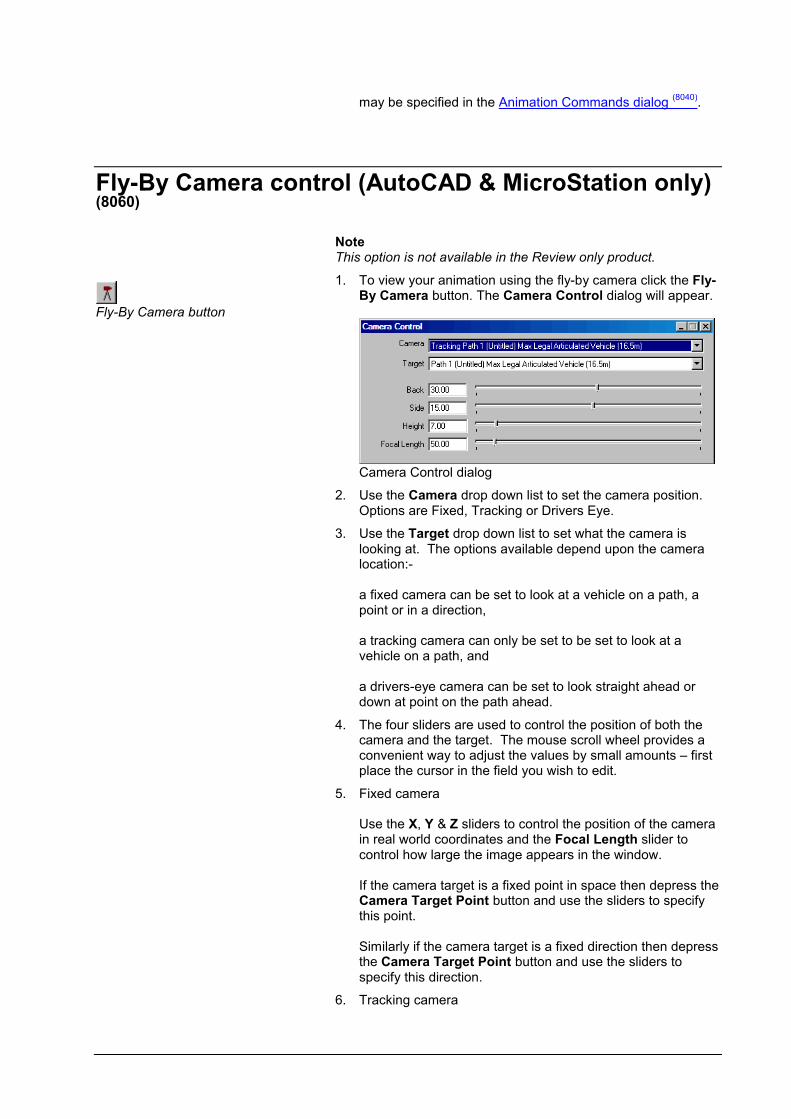
may be specified in the Animation Commands dialog (8040)
.
Fly-By Camera control (AutoCAD & MicroStation only) (8060)
Fly-By Camera button
NoteThis option is not available in the Review only product.
1. To view your animation using the fly-by camera click the Fly-By Camera button. The Camera Control dialog will appear.
Camera Control dialog
2. Use the Camera drop down list to set the camera position. Options are Fixed, Tracking or Drivers Eye.
3. Use the Target drop down list to set what the camera is looking at. The options available depend upon the camera location:-
a fixed camera can be set to look at a vehicle on a path, a point or in a direction,
a tracking camera can only be set to be set to look at a vehicle on a path, and
a drivers-eye camera can be set to look straight ahead or down at point on the path ahead.
4. The four sliders are used to control the position of both the camera and the target. The mouse scroll wheel provides a convenient way to adjust the values by small amounts – first place the cursor in the field you wish to edit.
5. Fixed camera
Use the X, Y & Z sliders to control the position of the camera in real world coordinates and the Focal Length slider to control how large the image appears in the window.
If the camera target is a fixed point in space then depress the Camera Target Point button and use the sliders to specify this point.
Similarly if the camera target is a fixed direction then depress the Camera Target Point button and use the sliders to specify this direction.
6. Tracking camera

User Manual for AutoTrack Review 327
Use the Back, Side & Height sliders to control the position of the camera relative to the vehicle in real world coordinates and the Focal Length slider to control how large the image appears in the window.
7. Drivers-Eye camera
Depress the Mirror View When Reversing button to display what the driver would see in the wing mirror on the inside of the turn when reversing.
If the camera is set to look down at the path then use the Look Ahead slider to control the distance of the viewpoint along the path.
Recording an animation as an AVI file (8050)
NoteThis option is not available in the Review only product.
Recording an animation can take some time depending upon the speed of your computer and the length and complexity of the animation.
The record option records everything in the selected area so we recommend that you switch off screen savers and do not use other applications whilst recording.
Record button
1. Having prepared an animation click the Record button in the AutoTrack Animation dialog. The AVI Options dialog will appear.
AVI options dialog
2. Use the Browse button to specify the File Name. The File Name field is read only. By default AutoTrack will create the AVI file in the same directory as the drawing file. If the drawing file has not been saved then it will create the file in your current directory.
3. Length in seconds is the duration of the resulting AVI movie. This is set by default to the real time length which is also shown in the adjacent text.
4. Frames per second is set by default to 3. Increasing this value will give you smoother movie but it will take longer to generate and the file size will be larger. Depending upon the design speed, you may also need to reduce your storage interval. We do not recommend a setting lower than 3 since
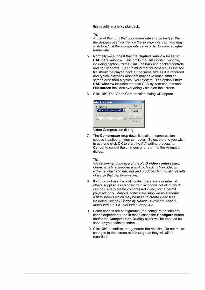
this results in a jerky playback.
TipA rule of thumb is that your frame rate should be less than the design speed divided by the storage interval. You may wish to adjust the storage interval in order to allow a higher frame rate.
5. Normally we suggest that the Capture window be set to CAD data window. This omits the CAD system window, including caption, frame, CAD toolbars and docked controls and edit windows. Bear in mind that for best results the AVI file should be played back at the same size as it is recorded and typical playback monitors may have much smaller screen area than a typical CAD system. The option Entire CAD window includes the host CAD system controls and Full screen includes everything visible on the screen.
6. Click OK. The Video Compression dialog will appear.
Video Compression dialog
7. The Compressor drop down lists all the compression codecs installed on your computer. Select the one you wish to use and click OK to start the AVI writing process, or Cancel to cancel the changes and return to the Animation dialog.
TipWe recommend the use of the XviD video compressioncodec which is supplied with AutoTrack. This codec is extremely fast and efficient and produces high quality results of a size that can be emailed.
8. If you do not use the XviD codec there are a number of others supplied as standard with Windows not all of which can be used to create compressed video, some permit playback only. Various codecs are supplied as standard with Windows which may be used to create video filesincluding Cinepak Codec by Radius, Microsoft Video 1, Indeo Video 5.1 & Intel Indeo Video 4.5.
9. Some codecs are configurable (the configure options are codec dependent) and in these cases the Configure button and/or the Compression Quality slider will be enabled as soon as you select a codec.
10. Click OK to confirm and generate the AVI file. Do not make changes to the screen at this stage as they will all be recorded.

User Manual for AutoTrack Review 329
AuditThe Audit tool lets you check your AutoTrack objects for basic errors. It can be used equally well by engineers at design stage to check their own work and later by checking authorities using the Review product.Changes to the audit results are saved with the drawing.
Audit dialog (8210)
1. Save your drawing and then click the Audit button. The Audit Exceptions dialog will appear.
Audit dialog
2. The left hand pane lists every AutoTrack entity in the drawing.
entities with no exceptions or with exceptions that have been approved are listed with a green tick,
entities with one or more exceptions that have been rejected are listed with a red cross, and
entities with one or more exceptions that are awaitingassessment are listed with an orange warning triangle and the exceptions are listed as ‘children’ in the tree view.
3. The content of the right hand pane varies according to what is selected in the tree view.
If you highlight an AutoTrack entity in the left hand pane then the right pane shows summary data for that entity, i.e. the name of the entity, the total exceptions and the exception status breakdown.
If you highlight an exception in the left hand pane then the right pane shows the detail of that exception.

4. To print an Audit report click the Print button. Refer to Print Audit Options dialog
(8220).
Audit dialog: Exception Details (8200)
1. Highlight an exception in the left hand pane and the Exception Details will appear in the right hand pane.
Audit dialog: Exception Details
243. Exceptions can have one for four statuses:-
Pending: An exception that has yet to be assessed,
Approved: An exception that has been assessed and approved unconditionally,
Approved With Conditions: An exception that has been assessed and approved subject to stated conditions, and
Rejected: An exception that has been assessed and rejected.
244. The top frame contains the details of the exception and, where appropriate, a location on the entity.
245. The middle section allows the engineer to provide a justification for, or explanation of, the exception together with space for a name or initials and a date.
246. Finally the lower section is for the checking authority to grant an approval status.
NoteThe Status can be changed regardless of whether any justification has been provided.

User Manual for AutoTrack Managing AutoTrack data 331
Print Audit Options dialog (8220)
1. Click the Print button on the Audit dialog. The Print Audit options dialog will appear.
Print Audit Options dialog
247. Tick Print Summary to include a summary of the audit results including number of entities and number of exceptions grouped by status.
248. Tick Print Tests Performed to list all the tests carried out.
249. Tick Print Exception Details to include full details of each exception.
Managing AutoTrack data
AutoTrack generates the same data regardless of the operating system or CAD system but it is stored in the CAD system native drawing format and CAD systems cannot always read each others drawing files.
However, AutoTrack incorporates a system to transfer data. Basically, data is exported from one CAD system and then imported in the receiving CAD system.
Exporting AutoTrack data (Export AutoTrack Data dialog) (5090)
1. Select Export AutoTrack data from the AutoTrack Utilities menu. The Export AutoTrack data dialog will appear.
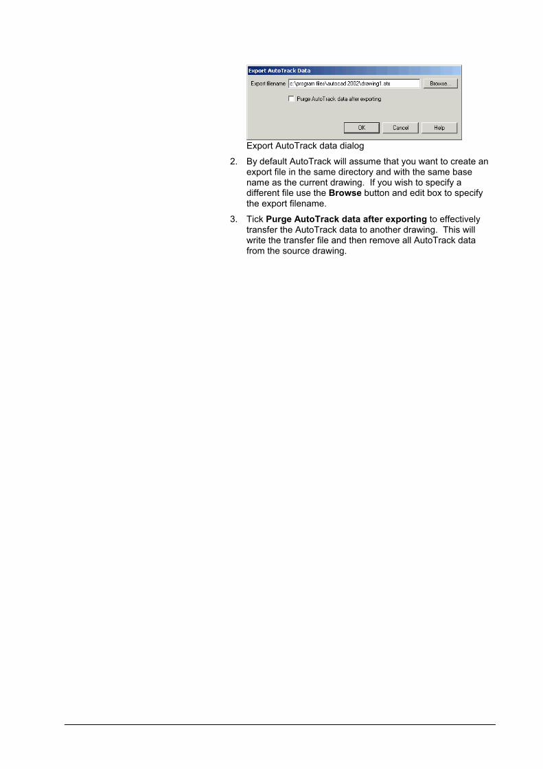
Export AutoTrack data dialog
2. By default AutoTrack will assume that you want to create an export file in the same directory and with the same base name as the current drawing. If you wish to specify a different file use the Browse button and edit box to specify the export filename.
3. Tick Purge AutoTrack data after exporting to effectively transfer the AutoTrack data to another drawing. This will write the transfer file and then remove all AutoTrack data from the source drawing.
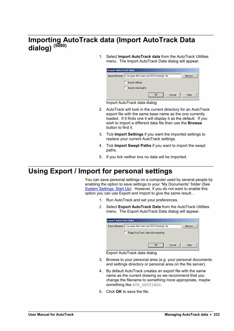
User Manual for AutoTrack Managing AutoTrack data 333
Importing AutoTrack data (Import AutoTrack Data dialog) (5080)
1. Select Import AutoTrack data from the AutoTrack Utilities menu. The Import AutoTrack Data dialog will appear.
Import AutoTrack data dialog
2. AutoTrack will look in the current directory for an AutoTrack export file with the same base name as the one currently loaded. If it finds one it will display it as the default. If you wish to import a different data file then use the Browsebutton to find it.
3. Tick Import Settings if you want the imported settings toreplace your current AutoTrack settings.
4. Tick Import Swept Paths if you want to import the swept paths.
5. If you tick neither box no data will be imported.
Using Export / Import for personal settingsYou can save personal settings on a computer used by several people by enabling the option to save settings to your “My Documents” folder (See System Settings: Start Up). However, if you do not want to enable this option you can use Export and Import to give the same result…
1. Run AutoTrack and set your preferences.
2. Select Export AutoTrack Data from the AutoTrack Utilities menu. The Export AutoTrack Data dialog will appear.
Export AutoTrack data dialog
3. Browse to your personal area (e.g. your personal documents and settings directory or personal area on the file server).
4. By default AutoTrack creates an export file with the same name as the current drawing so we recommend that you change the filename to something more appropriate, maybe something like ATR_SETTINGS.
5. Click OK to save the file.

6. When you next run AutoTrack select Import AutoTrack datafrom the AutoTrack Utilities menu.
7. When the Import AutoTrack data dialog appears tick only the Import settings box before clicking OK to load the settings.
Drawing file sizeAutoTrack data is stored in the host CAD drawing allowing you a number of benefits. However, as you use AutoTrack the host system frequently needs to make temporary copies of data. Most of these copies may be removed but, depending upon how your CAD system is configured, they often are not.
Luckily there are ways that you can recover the space taken by the working data.
Recovering space in AutoCAD drawings
By default AutoCAD does an incremental save of the drawing using QSAVE. This does not remove all deleted and temporary objects.
Use PURGE to remove all unused objects or SAVEAS to perform a full save and remove superseded data.
Recovering space in MicroStation drawings
Use COMPRESS DESIGN to remove superseded AutoTrack data.
Repair AutoTrack dataUnder certain circumstances and on rare occasions AutoTrack data links can become broken. So, for example, a layer used by an AutoTrack path may be deleted. The Repair AutoTrack data function is used to reinstate these links. It is very simple to use.
1. Select Repair AutoTrack data from the AutoTrack Utilities menu.
250. AutoTrack will scan all AutoTrack objects and try to repair any broken data links.
Purging AutoTrack data (Purge AutoTrack dialog) (5060)

User Manual for AutoTrack Managing AutoTrack data 335
The following procedures will remove ALL AutoTrack data from your drawing, including vehicles and reports. You will be given the option to retain the reports as AutoCAD entities but you should note that they will no longer be editable using AutoTrack.
AutoCAD version
1. Load the drawing that you wish to purge into AutoCAD.
2. Select Purge AutoTrack from the AutoTrack, Utilities menu.
3. Alternatively, type PURGEAUTOTRACK on the command line.
4. The Purge AutoTrack dialog will appear.
Purge AutoTrack dialog
5. Check the Convert AutoTrack reports box if you wish to leave any AutoTrack reports in your drawing as simple lines.
6. Click OK.
MicroStation version
1. Load the drawing that you wish to purge into MicroStation.
2. Select Purge AutoTrack from the AutoTrack, Utilities menu.
3. Alternatively, select Key in from the Utilities menu. The Key in dialog will appear. Select ATRACK from the first column and PURGE from the second. Click Key in.
4. The Purge AutoTrack dialog will appear.
Purge AutoTrack dialog
5. Check the Convert AutoTrack reports box if you wish to leave any AutoTrack reports in your drawing as simple lines.
6. Click OK.


User Manual for AutoTrack Glossary of Terms 337
Glossary of Terms
Active Hitch
A type of rear axle consisting of a drawbar with the bar facing rearwards linked to the front axle or articulation point (hence ‘active’).
Actual Wheelbase
The distance between the innermost axles on a tractor, or the distance from kingpin or drawbar pivot point to the innermost rear axle on a drawbar or semi-trailer.
Apron (or Overrun Area) (Parking)
A zone provided outside the Central Island for larger vehicles to track over. Note: The Apron is considered by some standards to be a part of (i.e. within) the Central Island and by others as part of the Circulatory Width (i.e. outside the Central Island). Either way, the outer limit of the Apron is the normal offside limit for normal vehicles turning 270 degrees.
AutoDrive
A means of driving the vehicle in which the path from a given position is calculated automatically as you move a target point (the cursor).
Authorisation code
A code needed to update the hardware lock to run each new version. May also be needed when you purchase extra features.
Axle Spacing
The distance between adjacent axles in a multi-axle group at the front or rear of a component.
Baseline
The baseline is the line that passes along the back of a row of parking bays.

Bay markings
The bay markings include the painted lines, symbols and hatching used to delineate the preferred position of the car.
Bay style
Each different composition of markings, safety zones, symbols and parking accessories is call a bay style.
Bay symbol
Bay symbols are the graphics painted within the bay and used to indicate, for example, bay usage.
Bend island
Bend islands are placed where a row of parking bays changes direction.
Castor Steering
Wheels that are part of a fixed axle group but that are free to rotate. Sometimes referred to as self-steered wheels.
Cats Whiskers
See Predictive Turning.
Central Island (or simply Island)
The normal offside limit (possibly kerbed) for vehicles turning 270 degrees. Note: In some standards there may be an Apron within the Central Island. AutoTrack treats the Central Island as the limit of turning for all vehicles if there is no apron or te apron is defined outside the island and as the limit for normal sized vehicles if there is an apron defined inside the island.
Circulatory Width
The Inscribed Circle radius minus the Island radius. Note: The preferred physical vehicle path limit will typically be inside this.
Cramp Angle
A term (seemingly used only by US fire departments) for the maxium wheel angle. See also ‘Wheel Cut’.
Cut-in Point
The point at which the spine of the element is tangential to the arc that it transcribes.
Cut-in Radius
The radius of the arc traversed by the Cut-in Point.

User Manual for AutoTrack Glossary of Terms 339
Definition Line
A virtual line representing a roadway limit. The physical Kerb Line may coincide with this line or maybe offset outside it.
Dongle
Slang name for a Hardware Lock.
Drag Lines
Lines drawn from the grips used to extend the path to the front most and rearmost grips on the vehicle. These lines vary in length according to the vehicle size and can be switched off.
Drawbar
A rigid towing bar attached rigidly to an axle. The bar and axle turn as one unit.
Drawbar Articulation Angle
The angle subtended at the axle pivot of a drawbar by the drawbar and associated trailer spine.
Drawbar Length
The length of a drawbar is measured from the centre of turning of the relevant axle group to the physical end of the drawbar. The coupling at the remote end must be defined separately in AutoTrack.
End island
End islands are non-parking areas placed at the ends of rows of parking bays.
DXF File
DXF stands for Drawing Exchange Format, a text file format used to transfer data between dissimilar CAD systems. Supported by many CAD systems.
Dynamic Edit
See Dynamic Editing.
Dynamic Editing
Editing a path by dragging the grips at target points (and / or intermediate points) to new locations. The path updates automatically when the grip is dropped.
Effective Fixed Axle
The effective fixed axle is the single axle that would have the same effect on the vehicle swept path as the fixed axle group. It is the centroid of the

group after the effects of retracted and self-steered axles are taken into account.
Effective Front Axle Offset
The offset of the effective front axle from the reference datum. Positive if the effective axle position is behind the reference datum.
Effective Front Track Width
The distance between outer faces of the front wheels to be used in path calculations.
Effective Rear Axle Offset
The offset of the effective rear axle from the reference datum. Positive if the effective axle position is behind the reference datum.
Effective Rear Track Width
The distance between outer faces of the rear wheels to be used in path calculations.
Effective Steered Axle
The effective steered axle offset is the single axle that would have the same effect on the vehicle swept path as a given steered axle group. It is the outermost axle of the steered axle group, i.e. the furthest forward on a front axle group and the furthest back on a rear axle group.
Effective Wheelbase
The distance between the Effective Front and Rear Axles.
Envelope
A single line representing the maximum body or wheel movement. In the case of vehicle bodies it is the outer limit of movement of any point on any body. In the case of wheels it is the outer limit of travel of any wheel.
Exit Overturn
An exit overturn is when a vehicle continues past the point at which it would normally start the turn (i.e. delays the start of the turn) prior to turning back and exiting the turn. The lateral deviation from the normal path is the exit overturn distance.
Fastest Line
The Fastest Line is the centreline of the path taken by a vehicle travelling as fast as possible through the junction. It is defined by various standards in different ways but usually there is a minimum offset from the apex of the path at entry, exit and island. There are also often specified starting and ending positions.

User Manual for AutoTrack Glossary of Terms 341
Follow
A means of driving a vehicle in which you specify a required path as a polyline and let the vehicle attempt to follow it.
Grips
Small squares that appear when an object is selected. Grips can be selected and moved using the mouse.
Hairpin marking
A type of parking bay marking comprising twin sidelines connected at the entrance.
Hardware Lock
A hardware lock or dongle is a security device that must be plugged into the parallel port of your computer to allow AutoTrack 5 to run.
In bay numbering
In bay numbering is when bay numbers are placed within each marked parking bay.
Independent Bogies
Multiple linked bogies arranged along a unit each with their own turntable. Also known as Tandem Axles. See also Pendel Axles.
Inscribed Circle
The Definition Line representing the outer limit of the Circulatory Width.
Intermediate Grips
Transient editing grips that are displayed along the path between Target Points to make path editing easier. An Intermediate Grip becomes a Target Point if it is selected.
Kerb Line
A line representing the roadside edge of the physical kerb.
Kerb Offset
The distance that the Kerb Line is offset (outside) the Definition Line.
Kerbside numbering
Kerbside numbering is when the bay numbers are placed adjacent to the bay.

Kerb-to-Kerb Turning Circle Radius
The radius of the smallest circle within which the vehicle's wheels can turn. It is assumed that this occurs when full steering lock is applied.
Lane Line
A line between lanes of traffic travelling in the same direction.
Layer
A means of grouping objects together within an AutoCAD drawing. The properties of layers (e.g. visibility) may be controlled independently of the objects they include. See also Level, the equivalent in MicroStation.
Level
A means of grouping objects together within a MicroStation drawing. The properties of layers (e.g. visibility) may be controlled independently of the objects they include. See also Layer, the equivalent in AutoCAD.
Linkage Proportion
The linkage proportion is the proportion of the articulation or wheel angle at one end of a unit that is applied to the axle group at the other end. The proportion may be specified in terms of angles or tangents of angles. In arithmetic terms if the linkage is on an angular basis the linkage proportion would be:-
LinkageProportion = LinkedAngle/PrimaryAngle
If the linkage is on a tangential basis the linkage proportion would be:-
LinkageProportion = tan(LinkedAngle)/tan(PrimaryAngle)
We understand that the latter is the more common form of linkage and in this case the effective cut in point offset is fixed for all primary angles.
Loci
The plural of locus. See Locus.
Lock
Steering angle; thus, maximum left lock is the maximum steering possible when turning left and right lock is the maximum when turning right.
Lock to lock time
Lock-to-lock time is the time that it takes the driver of the vehicle to turn the steering from the maximum angle (full lock) in one direction to maximum angle (full lock) in the opposite direction in a single continuous movement.
Locus
The path of a moving point in space. In the context of AutoTrack the path of the wheel tracks or the body vertices. Referred to in AutoTrack in it’s plural form loci.

User Manual for AutoTrack Glossary of Terms 343
Manual Drive
A means of driving a vehicle that uses a control overlay displayed on screen. The vehicle moves forwards, reverse, left and right according to the position of the cursor on the control overlay.
Maximum Drawbar Articulation Angle
The largest Drawbar Articulation Angle permitted.
Maximum Wheel Angle
The maximum angle of any wheel in a group, i.e. at the front or at the rear. This is normally the inside wheel on the innermost axle but may be otherwise if the widths of the axles in the group vary. See alse ‘Cramp Angle’ and ‘Wheel Cut’.
Minimum Cut-in Radius
The radius of the arc traversed by the Cut-in Point when the vehicle is turning at the Maximum Steering Angle.
Model Settings
The criteria that control the how a specified vehicle should behave in a specific situation. For example, a lower limit might be placed on the allowable lock rate.
Object enabler
An AutoCAD add-on that allows third party entities, like AutoTrack path entities, to be regenerated but not edited.
Offset Envelope
The envelope of maximum body or wheel movement with a further margin added. This may represent a safety or clearance margin.
Overrun Area
See Apron.
Overturn
A technique for reducing the vehicle cut-in on corners whereby the vehicle either turns temporarily in the opposite direction (side overturn) or delays the exit from the turn (exit overturn).
Overturn angle
When performing an overturn (side or exit) the overturn angle is the angular deviation of the wheels from the path the same vehicle would take if performing a non-overturn manoeuvre.

Pendel Axles
Multiple linked bogies arranged both across and along a unit that turn in much the same manner as Ackerman axles, i.e. those axles furthest away from the centre of turn follow the widest radius arc.
Predictive Turning
Predictive Turning is an AutoDrive feature that displays the limits of the vehicle path from the last position placed and the limits of body or wheel envelope from the ghosted unselected position. Also known as “Cat’s Whiskers”.
Primary Axle
The innermost axle of a group, i.e. the rearmost axle of a front axle group and the front most axle on a rear axle group.
Privacy post
Privacy posts are used to prevent use of parking bays by unauthorized personnel.
Rail wheels
Wheels designed to run on rails typically with an inner flange to prevent the wheel from derailing.
Retracted Axle
An axle that is present but not in contact with the road surface. Retracted axles are ignored when AutoTrack calculates the effective axle positions.
Safety post
Safety posts may be placed at the ends of parking bays to prevent vehicles from overshooting.
Safety zone
Safety zones are areas of extra space provided to meet special requirements and are measured from the centres of the bay side and entrance lines.
Script
A means of driving a vehicle by issuing commands such as; forwards 10 metres, turn left 30 degrees, continue for 5 metres.
Secondary steering
A turning axle group whose angle is controllable but which is not the main steering for the vehicle. The axle may be linked to another axle or independently controllable.

User Manual for AutoTrack Glossary of Terms 345
Secondary steering angle
The angle of an imaginary wheel at the centre of a secondary steering axle. See Secondary Steering.
Self-steering
Wheels that are part of a fixed axle group but that are free to rotate. Sometimes referred to as castors.
Separator Line
A line between lanes of traffic travelling in opposite directions.
Service type
The different usages of parking areas are called service types.
Side Overturn
A side overturn is when a vehicle starts a turn with opposite lock for a short distance prior to making the turn. The lateral deviation from the normal path is the side overturn distance.
Splitter
The splitter is formed by the boundaries of the entry and exit roadway Definition Lines and the Inscribed Circle.
Splitter Island
The Splitter may include a Splitter Island, especially if there are pedestrian crossings. The physical limits of the Splitter Island are normally inside the Splitter.
Steering Angle
The angle of an imaginary wheel at the centre of the controlling axle or coupling.
Stub axle
An axle carrying wheel(s) at only one end.
Stub axle length
The length of a stub axle is measured from the pivot point to the centre of the wheel group.
T-markings
A type of parking bay marking consisting of a T painted at the entrance between each adjacent parking bay . The leg of the T runs a short distance down the side of the bay and the cross runs part way along the entrance line.

Tandem Axles
See Independent Bogies.
Target Point
A point through which the vehicle must travel.
Tracking Point
The Tracking Point is the point on the vehicle that must pass through the specified Target Points. It is the point on the vehicle that you move and position when you use AutoDrive and also the point that follows the line in the Follow drive mode.
Tyred Wheels
Wheels with tyres fitted.
Vehicle class
Vehicles using parking areas are grouped into classes; vehicles with similar parking requirements.
Wall-to-Wall Turning Circle Radius
The radius of the smallest circle within which the vehicle's body can turn. It is assumed that this occurs when full steering lock is applied.
Wheel Cut
A term (seemingly used only by US fire departments) for the maxium wheel angle. See also ‘Wheel Cramp’.
Wheel Diameter
The diameter of the outer face of the tyre.
Wheel stop
Wheels stops are placed at the ends of bays to prevent the vehicle from overshooting.
Wheel Track
The distance between the outer faces of the wheels on an axle.
User Manual for AutoTrack Index 347
Index
3
3D Animations (AutoCAD & MicroStation only) 325
3D body shapes for animation 261
A
A few do's and don'ts 58Access to parking standards 285Access to parking standards in the Pool 286Access to vehicle libraries 213Access to vehicles in the Pool 214Active Hitch 337Actual Wheelbase 337Adding files to an installation 35Adjusting dynamics settings (not Rail) 209Adjusting model settings (Roads only) 206Adjusting speed settings 207Adjusting the path alignment (Path toolbar) 191Adjusting the path alignment using grip editing
195Adjusting the tracking point (not Rail) 208Adjusting the view (View toolbar) 188Adjusting transition settings (not Rail) 207Advanced animation options (Advanced
Animation dialog) (8005) 321AEC BS1192 Part 5 Layer/Level naming
Convention 122Animation Commands dialog (8040) 323Animations dialog (8010) 325Apron (or Overrun Area) (Parking) 337Attributes dialog 316Attributes dialog (3830) 91Audit 329Audit dialog (8210) 329Audit dialog: Exception Details (8200) 330Authorisation code 2, 337AutoCAD object enabler 32AutoDrive 337AutoDrive (Roads only) 158AutoDrive options (5110) 161AutoTrack hardware lock 1AutoTrack parking standards 285AutoTrack script commands 172AutoTrack Updates dialog (1970) 104
AutoTrack vehicle libraries 213Axle Spacing 337
B
Base layer or level name (Base Layer/Level Name dialog) (5120) 122
Baseline 337Bay markings 338Bay style 338Bay symbol 338Bend island 338Building vehicles using drag and drop 225
C
Capabilities 59Castor Steering 338Cats Whiskers 338Central Island (or simply Island) 338Changing your vehicle 184Checking vertical clearances 63Circulatory Width 338Compatibility with previous versions 214Configuring AutoCAD manually 36Configuring MicroStation, Bentley PowerDraft,
Bentley PowerCivil or Bentley MX manually 38
Context sensitive on-line help 72Copying standards and units using drag and
drop 290Copying vehicles and units using drag and drop
225Cramp Angle 338Creating a new group 226, 291Creating a new library (Library Details dialog)
(3520) 221Creating a new parking standard file (Parking
Standard File dialog) 287Creating the install script 33Creating vehicles 228Customising the Library Explorer view (Library
Explorer Columns dialog) (3515) 218Cut-in Point 338Cut-in Radius 338
D
Default Parking Standard dialog (4690) 292Default values 71Default Vehicle dialog (5100) 183Definition Line 339Demonstration copies 2Demonstration Version dialog (1800) 45Development & planning scenarios 62Dongle 339Drag Lines 339Drawbar 339Drawbar Articulation Angle 339Drawbar Length 339

Drawing Explorer (3300) 317Drawing file size 334Drawing Settings 115Drawing Settings: Construction Lines: Drag
Lines 134Drawing Settings: Construction Lines: Path 134Drawing Settings: Construction Lines: Steering
Pointer 134Drawing Settings: Dynamics (Roads & Airports)
(2180) 130Drawing Settings: Paths: Animations (not
Roads) (2150) 149Drawing Settings: Paths: Construction Lines
(3160) 133Drawing Settings: Paths: Layers (AutoCAD only)
(2060) 118Drawing Settings: Paths: Levels (MicroStation
pre-v8 only) (2065) 120Drawing Settings: Paths: Levels (MicroStation v8
onwards) (2067) 119Drawing Settings: Paths: Model (Roads &
Airports) (2070) 125Drawing Settings: Paths: Reports (3000) 132Drawing Settings: Paths: Reports: Discrete
(3020) 135Drawing Settings: Paths: Reports: Envelope
(3050) 141Drawing Settings: Paths: Reports: Graph (3070)
147Drawing Settings: Paths: Reports: Loci (3040)
139Drawing Settings: Paths: Reports: Offset
Envelope 1 143Drawing Settings: Paths: Reports: Profile (3060)
145Drawing Settings: Paths: Reports: Spaced
(3030) 137Drawing Settings: Paths: Speed (Roads, Rail &
Airports) (2080) 127Drawing Settings: Paths: Tracking Point (Roads
& Airports) (2170) 123Drawing Settings: Paths: Transitions (Roads &
Airports) (2085) 128Drawing Settings: Scale (2030) 117Drawing Settings: Units (2020) 116DXF File 339Dynamic Edit 339Dynamic Editing 339
E
Editing Aircraft bodies (Aircraft Body dialog) (4210) 265
Editing individual bays (Parking Bay Properties dialog) (4440) 280
Editing islands (Parking Island Properties dialog) (4460) 281
Editing Jet Blast contours (Jet Blast Contour dialog) (4230) 266
Editing parking row layout 282
Editing path properties (Path Properties dialog) 202
Editing rows (Parking Row Properties dialog) (4450) 278
Editing Tractor bodies (Tractor body dialog) (4220) 263
Editing Tram bodies (Tram Body dialog) (4200) 264
Editing vertices (Vertices dialog) (4180) 262Effective Fixed Axle 339Effective Front Axle Offset 340Effective Front Track Width 340Effective Rear Axle Offset 340Effective Rear Track Width 340Effective Steered Axle 340Effective Wheelbase 340End island 339Envelope 340Exit Overturn 340Exporting AutoTrack data (Export AutoTrack
Data dialog) (5090) 331Extending or trimming a path 201Extracting path data 211
F
Fastest Line 340Fastest line through roundabouts 63Features 59Finding vehicles online (Online Vehicle Library
Explorer) 3580 217Fly-By Camera control (AutoCAD & MicroStation
only) (8060) 326Follow 341Follow (not Rail) 169
G
Generating turn templates 151Getting help 71Grips 341Guided Drive (Rail only) 176
H
Hairpin marking 341Hardware Lock 341Height and ground clearance 260Help tutor 72How to use AutoTrack 60
I
Identifying and resolving problems 41Importing AutoCAD drawing files 268Importing AutoTrack data (Import AutoTrack
Data dialog) (5080) 333Importing outlines (Import Outlines dialog) (not
MicroStation version) (4190) 267In bay numbering 341

User Manual for AutoTrack Index 349
Independent Bogies 341Inscribed Circle 341Installing AutoTrack 14Installing AutoTrack from the web 31Installing the licence manager on a Novell
Netware server 10Installing the licence manager on a Windows
NT/2000/XP server 5Installing the licence monitor on a Windows
NT/2000/xp client computer 11Installing the NetHASP Licence Manager
software (Network version only) 5Installing the NetHASP Licence Monitor software
(Network version only) 11Installing the software 3Intermediate Grips 341
K
Kerb Line 341Kerb Offset 341Kerbside numbering 341Kerb-to-Kerb Turning Circle Radius 342
L
Lane Line 342Layer 342Layer / Level naming conventions 121Level 342Library Details: Library 221Library Details: Users (3530) 221Licences 2Limitations 59Linkage Proportion 342Loading AutoTrack 2.x vehicle libraries 214Loci 342Lock 342Lock to lock time 342Locus 342
M
Manual Drive 343Manual Drive (not Rail) 165Manual layout 71Master Reset dialog (2310) 95Maximum Drawbar Articulation Angle 343Maximum Wheel Angle 343Migrating from WinTrack 60Minimum Cut-in Radius 343Model Settings 343Modelling Active Hitches 62Modelling aircraft 62Modelling articulated semi-trailer vehicles 61Modelling combination steered vehicles 62Modelling conveyor systems 63Modelling drawbar and multi-trailer vehicles 61Modelling rigid vehicles 61
Modelling the effects of super elevation and side friction 63
Modelling trams and light rail vehicles 63Modelling vehicles with pushing tractors 62Modelling vehicles with steerable couplings 62Modifying, repairing or removing AutoTrack 28Mouse conventions 71Moving the NetHASP Licence Manager
(Network version only) 10Multiple heights 270, 271
N
Network licences 2Network version 4Notation conventions 71
O
Object enabler 343Offset Envelope 343On-line assistance 72Overrun Area 343Overturn 343Overturn angle 343
P
Park a Vehicle 180Parking Report (4410) 277Parking Standard File: Parking Standard File
287Parking Standard File: Users 287Parking Standard Group dialog (4670) 291Parking Standard: Bay Dimensions (4600) 302Parking Standard: Bay Markings (4580) 304Parking Standard: Bay Styles (4610) 310Parking Standard: Bay Symbols (4620) 306Parking Standard: Bend Islands (4470) 296Parking Standard: Construction Lines (4490)
315Parking Standard: End Islands (4480) 295Parking Standard: General (4500) 294Parking Standard: In Bay Numbering (4510) 297Parking Standard: Kerbside Bay Numbering
(4520) 298Parking Standard: Parking Meters (4530) 303Parking Standard: Privacy Posts (4540) 313Parking Standard: Safety Posts (4550) 312Parking Standard: Safety Zones (4560) 308Parking Standard: Service Types (4570) 300Parking Standard: Valid Bay Angles (4630) 301Parking Standard: Vehicle Classes (4640) 299Parking Standard: Wheel Stops (4650) 314Path Animation dialog (8020) 322Path Properties: Manoeuvres (5020) 204Path Properties: Manoeuvres: Dynamics 205Path Properties: Manoeuvres: General (5040)
205Path Properties: Manoeuvres: Model 205

Path Properties: Manoeuvres: Speed 205Path Properties: Manoeuvres: Tracking Point
205Path Properties: Manoeuvres: Transitions 205Path Properties: Path Notes (5010) 203Path Properties: Reports 206Path Properties: Vehicle 203Pendel Axles 344Placing access roads (4430) 275Placing discrete body outlines (5140) 210Placing rows of bays 273Positioning a vehicle (Position Vehicle dialog)
(6000) 186Positioning a vehicle interactively 185Predictive Turning 344Primary Axle 344Print Audit Options dialog (8220) 331Printing library or vehicle details (Print dialog)
(5070) 224Privacy post 344Properties 317Purging AutoTrack data (Purge AutoTrack
dialog) (5060) 334
R
Rail wheels 344Reading extracted data in Excel 211Reading pre-v5 AutoTrack libraries 60Recording an animation as an AVI file (8050)
327Recovering space in AutoCAD drawings 334Recovering space in MicroStation drawings 334Releasing network licences 101Removing a partially installed USB dongle 3Rental Version dialog (1820) 46Repair AutoTrack data 334Report Attributes dialog (3820) 91Report Wizard 84Report Wizard: Construction Lines (3800) 90Report Wizard: Finish (3810) 92Report Wizard: Graphical sub-reports (3710) 86Report Wizard: Path Annotation (3790) 87Report Wizard: Profile (3805) 88Report Wizard: Start (3700) 85Report Wizard: Steering & Articulation Graph
(3795) 89Resolving hardware lock problems 40Retracted Axle 344Retrieve Rental Licence dialog (1840) 47Running a silent install 34Running AutoTrack in AutoCAD 48Running AutoTrack in MicroStation 53Running stand-alone AutoTrack 43Running the Licence Manager on a remote
computer 41Running the Licence Manager on the same
computer as AutoTrack 40
S
Safety post 344Safety zone 344Saving a library 223Saving a parking standard file 289Savoy Basic Layer/Level naming convention 121Savoy Complex Layer/Level naming convention
121Savoy Standard Layer/Level naming convention
121Scale dialog (5130) 183Script 344Script (not Rail) 171Script Commands: Drive 174Script Commands: General 172Script Commands: New Path 172Script Commands: Positional 173Script Commands: Stop Conditions {S} 174Script Commands: Turn Conditions [T] 175Scripted 'silent' installations 33Secondary steering 344Secondary steering angle 345Selecting a Parking Standard 292Selecting a vehicle to drive 181Self-steering 345Separator Line 345Service type 345Settings 61Settings Wizard 73Settings Wizard: Articulation Limits (2455) 80Settings Wizard: Design Speed (2430) 78Settings Wizard: Dynamics (2460) 81Settings Wizard: Editing Units (2410) 75Settings Wizard: Finish (2480) 83Settings Wizard: Layers (2420) 76Settings Wizard: Scale (2400) 74Settings Wizard: Steering Limits (2450) 79Settings Wizard: Turn Transitions (2440) 77Settings Wizard: Updates (2470) 82Sharing a library (Share Data dialog) (3590) 224Sharing a parking standard (Share Data dialog)
289Side Overturn 345Simple animations (Basic Animation dialog)
(8000) 320Single user licences 2Single user version 3Some final points to note 26Some tips for defining trams (Rail only) 229Splitter 345Splitter Island 345Steering Angle 345Stub axle 345Stub axle length 345System Settings 93System Settings: AutoLoad (2005) 97System Settings: Directories (2200) 96System Settings: Internet (2210) 102System Settings: Language (2010) 99System Settings: Network (2015) 100

User Manual for AutoTrack Index 351
System Settings: Paths: AutoDrive (Roads only) (2100) 108
System Settings: Paths: Follow Drive (Roads only) (2120) 112
System Settings: Paths: Guided Drive (Rail only) (2130) 114
System Settings: Paths: Manual Drive (Roads only) (2110) 110
System Settings: Skill Level (2050) 107System Settings: Start Up (2000) 94System Settings: Updates (2190) 103System Settings: View (2040) 105
T
Tandem Axles 346Target Point 346Technical Support 42Template Wizard: Format (6530) 156Template Wizard: Model Settings (6515) 154Template Wizard: Turn Angles (6520) 155Template Wizard: Type (6500) 152Template Wizard: Vehicle (6510) 153The Advanced Editor 245The Getting Started dialog (not AutoTrack
Templates) (1900) 57The New Features dialog (1975) 56The Template Wizard 151The Vehicle Wizard 229T-markings 345To add a new user 222, 288To add a vertex to a row of parking bays 283To add the "loopback" address 40To adjust a bearing turn (not Rail) 198To adjust a parking row 283To adjust the articulation 185To adjust the vehicle start heading (not Rail)
192, 196To adjust the vehicle start position (not Rail) 192To adjust the vehicle start spine angles (not
Rail) 192, 197To adjust the vehicle start steering angle (not
Rail) 192To adjust the vehicle start steering angle (not
Rail) 196To adjust the view 167, 187To change dynamics settings 209To change the absolute articulation limits 207To change the absolute steering limits 206To change the design speed 207To change the heading of the vehicle 185To change the position of the vehicle 185To change the selected vehicle 184To change the tracking point 208To change the turn transiton types 207To close a vehicle library 182To copy a row of bays 282To copy the path 193To create a new vehicle 228To create or edit an AutoTrack script (6050) 171
To customise the parking report 277To delete a path 193To delete a row of bays 283To delete the last target point (not Rail) 195To display the parking report 277To drive backwards on an arc 159To drive forwards on an arc 159To edit a parking bay 280To edit a parking island 281To edit a parking row 278To edit a parking standard 293To edit an existing user (Maintain User dialog)
289To edit an existing user (Maintain Users dialog)
(3560) 223To edit the path properties 168To edit the path reports 168To enter grip editing mode 195To explode a row of bays 282To explode the path entity (or cell) 193To export a parking report 278To extend a path 201To extend a row of parking bays 283To extract path data 211To extract the software 31To generate a turn template 151To insert a new target point (not Rail) 194, 198To insert a vehicle details report 209To install the object enabler version from CD 32To install the software 31To install the software from the web 32To join two rows of parking bays 283To load an AutoTrack 2.x library 214To load an AutoTrack 2.x vehicle 215To load an AutoTrack script 172To load and run AutoTrack for AutoCAD
manually 50To load and run AutoTrack for MicroStation
manually… 55To move a path 197To move a row of bays 282To move a target point (not Rail) 197To move a vehicle details report 209To move target points (not Rail) 194To move the path 192To open a vehicle library 182To pan the image (e.g. if the vehicle is close to
the edge of the window) 188To pause driving 167To place a parallel row of bays 274To place a row of bays freehand 273To place an access road freehand 275To place an access road on a line 276To place discrete outlines 210To position the vehicle at a point on an existing
path 187To position the vehicle at the end of an existing
path 187To position the vehicle at the start of an existing
path 187

To redraw the path and update the reports 168To remove a target point (not Rail) 198To remove a vehicle details report 209To remove intermediate target points (not Rail)
195To reset any drawing rotation 188To rotate a row of bays 282To rotate the drawing automatically 188To rotate the drawing to the left 188To rotate the drawing to the right 188To rotate the path 193To run an AutoTrack script 172To run AutoTrack from the Taskbar Start
Programs Menu 48To run AutoTrack from the Taskbar Start
Programs menu… 53To run AutoTrack from within AutoCAD 48To run AutoTrack from within MicroStation… 54To save an AutoTrack script 172To see the steering pointer 192, 196To see the target points on a path 196To see the target points on the path 191To select a vehicle from a loaded library 182To set a default parking standard 292To set a default vehicle 182To set or change the heading of the entire
vehicle 186To set or change the position of the vehicle 186To set or change the starting orientation of a
selected spine 186To set or change the starting steering angle 186To show both the vehicle body and chassis 189To show only the vehicle body 189To show only the vehicle chassis 189To show or hide the vehicle trail 168To start driving 187To start driving (Control Overlay) (6020) 166To stretch a section in a path (not Rail) 197To terminate the current path 168To trim the end of the path 194, 199, 201To trim the start of the path 193, 198, 201To undo part of the path 168To undo the last operation 187To use AutoDrive in Arc mode 158To use AutoDrive in Bearing mode 159To use Follow 169To use Guided Drive 176To use Manual Drive 165To use Park a Vehicle 180To use Vertical Clearance 178To view the model settings 187To view the path properties 187To zoom in 188To zoom out 188Tracking Point 346Transfer Rental Licence dialog (1850) 47Trial copies 2Tyred Wheels 346
U
Undriveable Paths (5050) 200Uninstalling AutoTrack 35Unique parking standard names (Parking
Standard Name dialog) 275Unit Details dialog (4060) 246Unit Details: Axle Groups: Secondary Steering
Details (4090) 253Unit Details: Body / Outlines (4120) 258Unit Details: Couplings (4140) 269Unit Details: Front Axles / Rear Axles (4070) 249Unit Details: Servicing (Aircraft only) (4125) 271Unit Details: Steering (4150) 256Unit Details: Unit 247Units Details: Doors (Aircraft only) (4125) 270Unlocking a library (Unlock Library dialog)
(3550) 226Unlocking a parking standard file (Unlock
Parking Standard File dialog) (3555) 290Updating AutoTrack 35Using Export / Import for personal settings 333Using Follow to check fastest line 113
V
Vehicle class 346Vehicle Details dialog (4050) 245Vehicle details report 209Vehicle Diagram dialog (3570) 219Vehicle Group dialog (4040) 227Vehicle wizard: Aircraft Fuselage (aircraft only)
(7110) 242Vehicle wizard: Aircraft Tailplane (aircraft only)
(7100) 241Vehicle wizard: Aircraft wings (aircraft only)
(7090) 240Vehicle wizard: Axles (7010) 231Vehicle wizard: Body (7070) 237Vehicle wizard: Couplings (7060) 236Vehicle wizard: Drawbar (7050) 233Vehicle wizard: Finish (7130) 244Vehicle wizard: Manoeuvrability (7040) 235Vehicle wizard: Name (7000) 230Vehicle wizard: Pantograph (trams only) (7120)
243Vehicle wizard: Steering (not Rail) (7030) 234Vehicle wizard: Tractor body (7075) 238Vehicle wizard: Tram body (trams only) (7080)
239Vehicle wizard: Wheelbase (7020) 232Vertical Clearance 178Video tutorial 72Viewing a standard in a parking standard file or
the pool (Parking Standard Explorer dialog) (4400) 286
Viewing a vehicle in a library or the pool (Library Explorer dialog) (3510) 215
Viewing a vehicle used on a particular path 227Viewing AutoTrack paths in AutoCAD if you don't
have AutoTrack 52

User Manual for AutoTrack Index 353
Viewing or editing an existing vehicle 227Viewing or editing parking standards 293
W
Wall-to-Wall Turning Circle Radius 346Welcome dialog (1700) 44What AutoTrack can and can't do 59What's new in version 8? 64Wheel Cut 346Wheel Diameter 346Wheel stop 346Wheel Track 346Windows NT based systems (NT4, 2000, XP,
2003, Vista, Windows 7, etc.) 26