user manual for embedded system environment
TRANSCRIPT
Center for Embedded Computer SystemsUniversity of California, Irvine
User Manual for Embedded System Environment
ESE Version 2.0.0
Daniel D. Gajski, Samar Abdi, Gunar Schirner, Han-su Cho, YonghyunHwang, Lochi Yu, Ines Viskic and Quoc-Viet Dang
Technical Report CECS-08-14December 12, 2008
.Center for Embedded Computer Systems
University of California, IrvineIrvine, CA 92697-2620, USA
(949) 824-8919.
{gajski, sabdi, hschirne, hscho, yonghyuh, lochi.yu, iviskic,qpdang}@uci.edu
http://www.cecs.uci.edu/~ese

User Manual for Embedded System Environment:ESE Version 2.0.0Copyright © 2008 CECS, UC Irvine

User Manual for Embedded System Environment: ESE Version 2.0.0
Table of Contents1. Introduction................................................................................................................12. Usage ........................................................................................................................... 3
2.1. Manual Conventions .........................................................................................32.2. Starting ESE......................................................................................................4
2.2.1. Scripting.................................................................................................42.2.2. Environment Variables ...........................................................................5
3. Main Window .............................................................................................................73.1. Menu Bar ..........................................................................................................8
3.1.1. File Menu...............................................................................................83.1.2. Edit Menu...............................................................................................93.1.3. View Menu...........................................................................................103.1.4. Synthesis Menu....................................................................................103.1.5. Validation Menu...................................................................................113.1.6. Windows Menu ....................................................................................113.1.7. Help......................................................................................................12
3.2. Design Canvas.................................................................................................123.3. PE Window .....................................................................................................13
3.3.1. PE Window Processes..........................................................................143.3.2. PE Window Memories .........................................................................173.3.3. PE Window Channels ..........................................................................19
3.4. Channel Window.............................................................................................213.4.1. Channel Window Process Channels.....................................................223.4.2. Channel Window Memory Channels ...................................................233.4.3. Channel Window FIFO Channels ........................................................23
3.5. Database Window ...........................................................................................243.6. Output Window...............................................................................................253.7. Message Boxes................................................................................................26
3.7.1. Error Dialogs........................................................................................263.7.2. Information Dialogs .............................................................................27
4. Functionality.............................................................................................................294.1. Application Preferences ..................................................................................29
4.1.1. Application Preferences .......................................................................294.2. Design Handling .............................................................................................32
4.2.1. Design Creation ...................................................................................344.2.2. Design Opening ...................................................................................344.2.3. Design Saving ......................................................................................364.2.4. Design Reloading.................................................................................374.2.5. Design Closing.....................................................................................37
© 2008, CECS iii
User Manual for Embedded System Environment: ESE Version 2.0.0
4.2.6. Design Exporting .................................................................................384.2.7. Design Settings Editing .......................................................................394.2.8. Design Source Viewing........................................................................404.2.9. ESE Exiting..........................................................................................41
4.3. Transaction Level Modeling ...........................................................................414.3.1. PE Allocation.......................................................................................424.3.2. PE Mapping .........................................................................................454.3.3. Network Allocation..............................................................................494.3.4. Channel Mapping.................................................................................58
4.4. TLM Synthesis................................................................................................634.4.1. Generate Functional TLM....................................................................644.4.2. Generate TLM......................................................................................64
4.5. TLM Validation...............................................................................................644.5.1. Simulate Functional TLM....................................................................644.5.2. Simulate Timed TLM...........................................................................64
4.6. Performance Analysis .....................................................................................644.6.1. PE Performance Analysis ....................................................................654.6.2. Bus Performance Analysis ...................................................................674.6.3. CE Performance Analysis ....................................................................69
4.7. Window Management .....................................................................................695. Data Modeling ..........................................................................................................72
5.1. Processing Element (PE) Data Model.............................................................725.1.1. Datapath Model....................................................................................725.1.2. Execution Model ..................................................................................755.1.3. Memory Model ....................................................................................78
5.2. Bus Model.......................................................................................................81A. XML stylesheet for PE Data Model.......................................................................84
A.1. Data Type .......................................................................................................84A.2. Elements.........................................................................................................84
B. XML stylesheet for Bus Models .............................................................................88C. Example XMLs........................................................................................................89
C.1. Example XML for MicroBlaze ......................................................................89C.2. Example XML for Custom Hardware ..........................................................105C.3. Example XML for OPB ...............................................................................113
© 2008, CECS iv

User Manual for Embedded System Environment: ESE Version 2.0.0
List of Tables5-1. Model......................................................................................................................725-2. Attribute..................................................................................................................725-3. Model......................................................................................................................725-4. Model......................................................................................................................725-5. Attribute..................................................................................................................735-6. Model......................................................................................................................735-7. Attribute..................................................................................................................735-8. Model......................................................................................................................745-9. Attribute..................................................................................................................745-10. Model....................................................................................................................745-11. Attribute................................................................................................................755-12. Model....................................................................................................................755-13. Attribute................................................................................................................755-14. Model....................................................................................................................765-15. Attribute................................................................................................................765-16. Model....................................................................................................................765-17. Attribute................................................................................................................775-18. Model....................................................................................................................775-19. Attribute................................................................................................................775-20. Model....................................................................................................................785-21. Attribute................................................................................................................785-22. Model....................................................................................................................785-23. Model....................................................................................................................785-24. Attribute................................................................................................................795-25. Model....................................................................................................................795-26. Attribute................................................................................................................795-27. Model....................................................................................................................805-28. Attribute................................................................................................................805-29. Model....................................................................................................................805-30. Attribute................................................................................................................805-31. Attribute................................................................................................................81
List of Figures1-1. User Manual for Embedded System Environment. ..................................................13-1. Main Window of ESE...............................................................................................73-2. Design Canvas. .......................................................................................................13
© 2008, CECS v

User Manual for Embedded System Environment: ESE Version 2.0.0
3-3. PE Window. ............................................................................................................143-4. Channel Window.....................................................................................................213-5. Database Window. ..................................................................................................253-6. Output Window.......................................................................................................253-7. Error dialog.............................................................................................................273-8. Information dialog. .................................................................................................274-1. Edit Preferences dialog. ..........................................................................................304-2. Database Selection dialog.......................................................................................304-3. SystemC Path Selection dialog...............................................................................314-4. Design Open dialog. ...............................................................................................354-5. Design Save dialog. ................................................................................................364-6. Design Export dialog. .............................................................................................384-7. Design Settings (TLM Compiler tab) dialog. .........................................................394-8. Design Source Viewing dialog. ..............................................................................404-9. PE Allocation result................................................................................................434-10. PE Parameters dialog............................................................................................434-11. Process Renaming dialog......................................................................................464-12. Adding Sources to a Process (C File) dialog. .......................................................464-13. Adding Sources to a Process (C File) dialog. .......................................................474-14. Adding a Process Port to a Process dialog. ..........................................................484-15. Bus Allocation result. ...........................................................................................504-16. Bus Parameters dialog. .........................................................................................514-17. Bus Addressing dialog..........................................................................................524-18. Bus Synchronization dialog..................................................................................524-19. CE Allocation result. ............................................................................................544-20. CE Parameters dialog. ..........................................................................................554-21. CE Scheduling dialog. ..........................................................................................554-22. Port Adding dialog................................................................................................574-23. Connecting to the bus dialog. ...............................................................................584-24. Add Channel context menu. .................................................................................584-25. Process-to-Process Channel dialog.......................................................................594-26. Memory Channel dialog. ......................................................................................604-27. FIFO Channel dialog. ...........................................................................................624-28. PE Performance Analysis dialog. .........................................................................654-29. PE Computation graph dialog...............................................................................654-30. Process Computation graph dialog. ......................................................................664-31. Bus Performance Analysis dialog.........................................................................674-32. Bus Data Transfer Analysis dialog. ......................................................................68
© 2008, CECS vi

User Manual for Embedded System Environment: ESE Version 2.0.0
Chapter 1. Introduction
Figure 1-1. User Manual for Embedded System Environment.
The Embedded System Environment(ESE) is shown in Figure 1-1. The input to ESEfront-end is the system definition consisting of a platform and application code. A libraryof processing elements, buses, bridges and RTOS is provided in ESE to develop such aplatform. The retargetable timing estimation tool in ESE is used to annotate timing to theapplication code based on the mapping of application code on the platform components.The timed application and platform are input to the Transaction Level Model (TLM)generator tool that uses the bus and bridge models to generate a SystemC TLM. ThisSystemC TLM can be simulated by any commercial or freely available SystemC simu-lator to provide the performance metrics. The designer can use the metrics to optimize(i) the application code, (ii) the platform, and/or (iii) the mapping from the applicationto the platform. Since timing estimation and high-speed TLM generation in ESE areextremely fast, TLMs can be generated and simulated in minutes. This allows fast andearly exploration of various design options with ESE.
The ESE provides an environment for modeling, estimation and validation. It includes agraphical user interface (GUI) and a set of tools to facilitate the design flow and perform
© 2008, CECS 1

User Manual for Embedded System Environment: ESE Version 2.0.0
the aforementioned optimization steps. The two major components of the GUI are theDesign Decision Interface (DDI) and the Validation User Interface (VUI). The DDIallows designers to make and input design decisions, such as allocation of HW andSW components in the platform, and the mapping of application to the platform. Withdesign decisions made, TLM generation and estimation tools can be invoked to generatefunctional and timed TLMs. The VUI allows the simulation of all TLMs using the OSCISystemC simulator to validate the design at each stage of the design flow.
With the assistance of the GUI and automatic TLM generation tools, it is relatively easyfor designer to step through the design process. With the editing, browsing and algorithmselection capability provided by the GUI, the C application processes can be efficientlycaptured by designers. Communication channels between the application processes canbe created using an intuitive channel wizard. The HW platform can be allocated easilyby simple drag-drop of components from the database. The processing elements(PEs),bridges and buses can be connected using ports. The mapping of the procesess to PEsand channels to buses/routes can also be done easily in the GUI. The TLM generationtools can be used to verify both the functional correctness of the design and to accuratelyestimate the performance. Various statistics are generated automatically by the tied TLMsimulation. These statistics can be viewed graphically using the GUI.
© 2008, CECS 2

User Manual for Embedded System Environment: ESE Version 2.0.0
Chapter 2. Usage
In the following sections, the general usage of the ESE application will be outlined.Followed by a description of basic formatting conventions used throughout the manual,information pertinent to running the ESE application will be provided.
2.1. Manual ConventionsThe following style and formatting conventions are used throughout the text of this man-ual to refer to commands, actions, or GUI elements:
Command
Refers to a command or other data input typed in and entered by the user.
Message
Refers to a log or other text message produced by the ESE application on the screen.
Key
Refers to a key that a user can press on the keyboard.
Label
Refers to a button, menu or any other general label in the GUI of the ESE mainapplication.
Win::Sub
Refers to a sub-item inside one of the parts of the ESE application main window.
Win refers to one of the following parts of the application main window (seeChapter 3 Main Window (page 7)):
• Main represents the Main Window itself (i.e. its menu or tool bar).
• Project represents the Project Window.
• Output represents the Output Window.
• Design represents the Design Window.
Sub refers to drop-down menus or sub windows (tabs):
© 2008, CECS 3

User Manual for Embedded System Environment: ESE Version 2.0.0
• For the Main Window, Sub is either File, View, Project, Synthesis, or Win-dows (drop-down menus introduced in Section 3.1 Menu Bar (page 8)).
• For the Project Window, Sub is either Models, Imports, or Sources (tabs in-troduced in.
• For the Output Window, Sub is either Compile or Refine (tabs introduced in.
• For the Design Window, Sub is either Hierarchy, Behaviors, or Channels(sidebar tabs introduced.
For example, Project::Models refers to the models tab in the Project Window.
Menu−→Command
Refers to a main menu or context menu command (described in) where Commandrefers to the menu command and Menu refers to a main menu entry or to a contextmenu in a named subwindow (tab).
For example, Main::File−→Open... refers to the Open... commandin the File menu of the Main Window menu bar. On the other hand,Project::Models−→Open refers to the Open command in the context menu ofthe Project Window Models tab.
2.2. Starting ESEESE is invoked by entering
% ese
at the command line prompt (%). This will start the application and open the main win-dow (Chapter 3 Main Window (page 7)) of the combined SCE graphical user interface(GUI).
2.2.1. Scripting
ESE supports scripting of the complete environment from the command line without theneed to invoke the GUI. For scripting purposes, a GUI-less command shell of ESE can
© 2008, CECS 4

User Manual for Embedded System Environment: ESE Version 2.0.0
be invoked by entering
% scshat the command line prompt (%). This will start the ESE shell without the GUI layer.Instead, a prompt (>>) is offered to enter commands that allow to drive the ESE envi-ronment interactively (or from ESE shell scripts read from files supplied on the scshcommand line).
The ESE shell is based on an embedded Python interpreter. As such, it conforms toPython syntax and the full semantics of the Python language is available. In addition,the ESE shell extends the Python interpreter with an API for access to ESE function-ality. However, the ESE shell API only provides undocument low-level access to ESEinternals for developers.
For user-level scripting of ESE by designers, a complete set of high-level scripts on topof the ESE shell are available. The set of scripts provides a convenient command-lineinterface for all necessary ESE functionality . Together with command-line interfacesto model refinement tools and to the SpecC compiler , complete scripting of the ESEdesign flow from the command line, through shell scripts or via Makefiles is possible.
2.2.2. Environment Variables
HOME
Determines the location of the user’s home directory and consequently the defaultpath to the file with user-specific application preferences ($HOME/.ese/eserc).
ESERC_PATH
Determines the list of directories where files serrc with user-specific applicationpreferences are stored. Multiple directories can be provided, separated by colons(“:”). Directories are searched for and preference files are read in the given order,i.e. preference files in later directories can override settings in earlier ones. Modifiedpreferences will be written to the first directory in the list that is writeable by theuser.
If ESERC_PATH is not set, the location (directory) of the user-specific serrc filedefaults to $HOME/.ese.
© 2008, CECS 5

User Manual for Embedded System Environment: ESE Version 2.0.0
© 2008, CECS 6

User Manual for Embedded System Environment: ESE Version 2.0.0
Chapter 3. Main Window
Figure 3-1. Main Window of ESE.
The primary GUI of ESE is the Main Window, which is displayed in Figure 3-1. TheMain Window consists of eight parts:
1. A Menu Bar that contains seven columns of commands. Each column is a drop-down menu.
2. A Tool Bar that contains a list of short-cut icons. Each icon represents a commandin the menu bar.
3. A PE Window that contains the current design’s PE’s.
4. A Channel Window that contains the current design’s busses and channels.
© 2008, CECS 7

User Manual for Embedded System Environment: ESE Version 2.0.0
5. A Database Window that contains the current database’s available components.
6. A Design Canvas that contains the graphical representations of the objects of thecurrent design.
7. An Output Window.
8. A Status Bar that displays the current status of ESE, such as Loading... or Ready.
In this section, we introduce organization-related and display-related details of MenuBar, PE Window, Channel Window, Database Window, Design Canvas, and Output Win-dow. Some windows contain drop-down menus or pop-up menus. The menus furthercontain design commands. The usage and functionality behind the commands will bedescribed later.
3.1. Menu BarThe Menu Bar contains seven main menu entries: File, Edit, View, Synthesis, Valida-tion, Windows, and Help. Each main menu entry is a drop-down menu which containsa number of commands. In general, unless otherwise noted, selecting a main menu entrywill apply the corresponding action to the currently active design, i.e. to the design thatis currently open. If there is no currently active design, menu commands will silentlyfail (do nothing).
3.1.1. File Menu
The File menu contains ten commands:
File−→New...
Selecting New... will create a new design file (seeSection 4.2.1 Design Creation (page 34)).
File−→Open...
Selecting Open... will allow loading and opening of an existing design file (seeSection 4.2.2 Design Opening (page 34)).
© 2008, CECS 8

User Manual for Embedded System Environment: ESE Version 2.0.0
File−→Close
Selecting Close will close the current design (seeSection 4.2.5 Design Closing (page 37)).
File−→Reload
Selecting Reload will trigger reloading of the current design file from disk (e.g.in case the file has changed on disk or reverting to the last saved version) (seeSection 4.2.4 Design Reloading (page 37)).
File−→Save
Selecting Save will save the current design file (seeSection 4.2.3 Design Saving (page 36)).
File−→Save As...
Selecting Save As... will save the current design file as a another file (seeSection 4.2.3 Design Saving (page 36)).
File−→Export...
Selecting Export... will allow saving and exporting of the current design in a com-pressed file format (see Section 4.2.6 Design Exporting (page 38)).
File−→Settings...
Selecting Settings... will display the settings of the current design file (seeSection 4.2.7 Design Settings Editing (page 39)).
File−→Exit
Selecting Exit will exit from and quit ESE (seeSection 4.2.9 ESE Exiting (page 41)).
© 2008, CECS 9

User Manual for Embedded System Environment: ESE Version 2.0.0
3.1.2. Edit Menu
The Edit menu contains one command:
Edit−→Preferences...
Selecting Preferences... will allow viewing and modifying of application prefer-ences (see Section 4.1 Application Preferences (page 29)).
3.1.3. View Menu
The View menu contains three commands:
View−→Source...
Selecting Source... will allow viewing of the source file of the current design (seeSection 4.2.8 Design Source Viewing (page 40)).
View−→Chart...
Selecting Chart... will display the chart of the current design.
View−→Connectivity...
Selecting Connectivity... will display the connectivity chart of the current design.
3.1.4. Synthesis Menu
The Synthesis menu contains five commands:
Synthesis−→Generate Functional TLM...
Selecting Generate Functional TLM... generates the functional tlm for the currentdesign (see Section 4.4.1 Generate Functional TLM (page 64)).
Synthesis−→Generate Timed TLM...
Selecting Generate Timed TLM... generates the timed tlm for the current design(see Section 4.4.2 Generate TLM (page 64)).
© 2008, CECS 10

User Manual for Embedded System Environment: ESE Version 2.0.0
Synthesis−→Select Board...
Selecting Select Board... presents a sub-menu, which allows selection of the boardto which the current design can be synthesized.
Synthesis−→Synthesize to Board...
Selecting Synthesize to Board... synthesizes the current design onto the selectedboard.
Synthesis−→Stop
Selecting Stop stops any running generation and synthesizing processes for thecurrent design.
3.1.5. Validation Menu
The Validation menu contains four commands:
Validation−→Simulate Functional TLM...
Selecting Simulate Functional TLM... simulates the functional tlm for the currentdesign (see Section 4.5.1 Simulate Functional TLM (page 64)).
Validation−→Simulate Timed TLM...
Selecting Simulate Timed TLM... simulates the timed tlm for the current design(see Section 4.5.2 Simulate Timed TLM (page 64)).
Validation−→Kill Simulation...
Selecting Kill Simulation... presents a sub-menu allowing the selection of whichactive simulation to terminate from the current design.
Validation−→View Log...
Selecting View Log... shows the log of the current design.
© 2008, CECS 11

User Manual for Embedded System Environment: ESE Version 2.0.0
3.1.6. Windows Menu
The Windows menu contains two commands:
Windows−→Output Window
Selecting Output Window will display or undisplay the Output Window (seeSection 3.6 Output Window (page 25)).
Windows−→Toolbars
Selecting Toolbars presents a sub-menu allowing the selection of toolbar(s) toshow/hide.
3.1.7. Help
The Help menu contains two commands:
Help−→Manual...
Selecting Manual... will open the ESE user manual in the online help browser.
Help−→About...
Selecting About... will pop up a dialog with version and copyright information ofthe ESE environment.
© 2008, CECS 12

User Manual for Embedded System Environment: ESE Version 2.0.0
3.2. Design Canvas
Figure 3-2. Design Canvas.
The Design Canvas displays the content and the attributes of an opened design graphi-cally, and it allows browsing and manipulating of the design objects. The Design Canvasis displayed in Figure 3-2.
The canvas supports modifying the layout and attributes of the design via drag-and-dropand through a context menu. Dragging objects from the Database Window adds an objectto the design. Dragging objects within the Design Canvas repositions the object accord-ingly. Deletion, renaming, adding and removing ports, as well as viewing properties areaccessed via the context menu and available dependent upon the type of object currentlyselected (see Section 4.2 Design Handling (page 32)).
© 2008, CECS 13

User Manual for Embedded System Environment: ESE Version 2.0.0
3.3. PE Window
Figure 3-3. PE Window.
In the PE Window side bar, all the processes, source files, local memories and localchannels associated with each PE in the design are listed. Every PE is represented asa tab in the PE Window. Unmapped processes, local memories, and local channels aredisplayed in the Unmapped tab. The PE Window is displayed in Figure 3-3.
Each PE tab contains processes, local memories, and local channels. The Processescategory contains all processes for the PE. If available, each process displays associ-ated Process Ports and Source Files. Internal Memories and Exposed Memoriesare displayed under the Memories category. The Channels category displays the PE’sProcess Channels, Memory Channels and FIFO Channels.
3.3.1. PE Window Processes
Right-clicking on the Processes category in the PE Window opens a context-menupop-up for the selected processes. The context menu for Processes contains two com-mands:
Add Process
Selecting Add Process will add a new instance of the selected entity (seeSection 4.3.2 PE Mapping (page 45)).
© 2008, CECS 14

User Manual for Embedded System Environment: ESE Version 2.0.0
Remove All Processes
Selecting Remove All Processes will remove all entities of the selected type (seeSection 4.3.2 PE Mapping (page 45)).
Right-clicking on a process under the Processes category in the PE Window opensa context-menu pop-up for the selected process. The context menu for each processcontains eight commands:
Rename Process
Selecting Rename Process will rename the selected entity (seeSection 4.3.2 PE Mapping (page 45)).
Add Process
Selecting Add Process will add a new instance of the selected entity (seeSection 4.3.2 PE Mapping (page 45)).
Remove Process(es)
Selecting Remove Process(es) will remove all entities of the selected type (seeSection 4.3.2 PE Mapping (page 45)).
Add .C File(s)
Selecting Add .C File(s) will add a new source file of the specified type (seeSection 4.3.2 PE Mapping (page 45)).
Add .H File(s)
Selecting Add .H File(s) will add a new source file of the specified type (seeSection 4.3.2 PE Mapping (page 45)).
Remove All Source File(s)
Selecting Remove All Source File(s) will remove all entities of the selected typefrom the process (see Section 4.3.2 PE Mapping (page 45)).
Add Process Port
Selecting Add Process Port will add a new instance of the selected entity to theprocess (see Section 4.3.2 PE Mapping (page 45)).
© 2008, CECS 15

User Manual for Embedded System Environment: ESE Version 2.0.0
Remove All Process Port(s)
Selecting Remove All Process Port(s) will remove all entities of the selectedtype from the process (see Section 4.3.2 PE Mapping (page 45)).
Right-clicking on Process Ports under a Process in the PE Window opens a context-menu pop-up for the selected process ports. The context menu for Process Ports con-tains two commands:
Add Process Port
Selecting Add Process Port will add a new instance of the selected entity to theprocess (see Section 4.3.2 PE Mapping (page 45)).
Remove All Process Port(s)
Selecting Remove All Process Port(s) will remove all entities of the selectedtype from the process (see Section 4.3.2 PE Mapping (page 45)).
Right-clicking on a process port under Process Ports in the PE Window opens acontext-menu pop-up for the selected process class. The context menu for each processport contains three commands:
Add Process Port
Selecting Add Process Port will add a new instance of the selected entity to theprocess (see Section 4.3.2 PE Mapping (page 45)).
Remove Process Port(s)
Selecting Remove Process Port(s) will remove the selected entities of the se-lected type from the process (see Section 4.3.2 PE Mapping (page 45)).
Properties
Selecting Properties will open a properties dialog box the selected entity from theprocess. The user is able to rename the function names for the entity in this dialogbox (see Section 4.3.2 PE Mapping (page 45)).
Right-clicking on Source Files under a process in the PE Window opens a context-menu pop-up for the selected source files. The context menu for Source Files containsthree commands:
© 2008, CECS 16

User Manual for Embedded System Environment: ESE Version 2.0.0
Add .C File(s)
Selecting Add .C File(s) will add a new source file of the specified type (seeSection 4.3.2 PE Mapping (page 45)).
Add .H File(s)
Selecting Add .H File(s) will add a new source file of the specified type (seeSection 4.3.2 PE Mapping (page 45)).
Remove All Source File(s)
Selecting Remove All Source File(s) will remove all entities of the selected typefrom the process (see Section 4.3.2 PE Mapping (page 45)).
Right-clicking on a source file under Source Files in the PE Window opens a context-menu pop-up for the selected source files. The context menu for each source file containsfour commands:
Add .C File(s)
Selecting Add .C File(s) will add a new source file of the specified type (seeSection 4.3.2 PE Mapping (page 45)).
Add .H File(s)
Selecting Add .H File(s) will add a new source file of the specified type (seeSection 4.3.2 PE Mapping (page 45)).
Remove File(s)
Selecting Remove File(s) will remove all selected entities of the selected typefrom the process (see Section 4.3.2 PE Mapping (page 45)).
View Source
Selecting View Source will open the Design Viewer and show the source codefor the file (see Section 4.3.2 PE Mapping (page 45)).
3.3.2. PE Window Memories
Right-clicking on the Memories category in the PE Window opens a context-menupop-up for the selected process class. The context menu for Memories contains threecommands:
© 2008, CECS 17

User Manual for Embedded System Environment: ESE Version 2.0.0
Add Exposed Memory
Selecting Add Exposed Memory will add a new instance of the selected entity(see Section 4.3.2 PE Mapping (page 45)).
Add Internal Memory
Selecting Add Internal Memory will add a new instance of the selected entity (seeSection 4.3.2 PE Mapping (page 45)).
Remove All Selected Memories
Selecting Remove All Selected Memories will remove all entities of the selectedtype (see Section 4.3.2 PE Mapping (page 45)).
Right-clicking on the Exposed sub-category under the Memories category in the PEWindow opens a context-menu pop-up for the selected process class. The context menufor Exposed contains two commands:
Add Exposed Memory
Selecting Add Exposed Memory will add a new instance of the selected entity(see Section 4.3.2 PE Mapping (page 45)).
Remove All Exposed Memories
Selecting Remove All Exposed Memories will remove all entities of the selectedtype (see Section 4.3.2 PE Mapping (page 45)).
Right-clicking on a memory under the Exposed sub-category in the PE Window opensa context-menu pop-up for the selected process class. The context menu for Exposedcontains four commands:
Rename Memory
Selecting Rename Memory will allow the user to rename the selected entity (seeSection 4.3.2 PE Mapping (page 45)).
Add Exposed Memory
Selecting Add Exposed Memory will add a new instance of the selected entity(see Section 4.3.2 PE Mapping (page 45)).
© 2008, CECS 18

User Manual for Embedded System Environment: ESE Version 2.0.0
Remove Selected Memories
Selecting Remove Selected Memories will remove selected entities of the se-lected type from the process (see Section 4.3.2 PE Mapping (page 45)).
Set Memory Size
Selecting Set Memory Size will allow the user to set the size of the entity underthe Details column (see Section 4.3.2 PE Mapping (page 45)).
Right-clicking on the Internal sub-category under the Memories category in the PEWindow opens a context-menu pop-up for the selected process class. The context menufor Internal contains two commands:
Add Internal Memory
Selecting Add Internal Memory will add a new instance of the selected entity (seeSection 4.3.2 PE Mapping (page 45)).
Remove All Internal Memories
Selecting Remove All Internal Memories will remove all entities of the selectedtype (see Section 4.3.2 PE Mapping (page 45)).
3.3.3. PE Window Channels
Right-clicking on the Channels category in the PE Window opens a context-menu pop-up for the selected channel class. The context menu for Channels contains one com-mand:
Remove Selected Channels
Selecting Remove Selected Channels will remove all entities of the selectedtype (see Section 4.3.2 PE Mapping (page 45)).
Right-clicking on the Process Channels sub-category under the Channels category inthe PE Window opens a context-menu pop-up for the selected channel class. The contextmenu for Process Channels contains one command:
Remove Selected Channels
Selecting Remove Selected Channels will remove all entities of the selectedtype (see Section 4.3.2 PE Mapping (page 45)).
© 2008, CECS 19

User Manual for Embedded System Environment: ESE Version 2.0.0
Right-clicking on a channel under the Process Channels sub-category in the PE Win-dow opens a context-menu pop-up for the selected channel class. The context menu forProcess Channels contains two commands:
Remove Channel(s)
Selecting Remove Channel(s) will remove all selected entities of type (seeSection 4.3.2 PE Mapping (page 45)).
Properties
Selecting Properties will open a properties dialog box for the selected entity fromthe process. The user is able to modify port and route properties in this dialog box.
Right-clicking on the Memory Channels sub-category under the Channels category inthe PE Window opens a context-menu pop-up for the selected channel class. The contextmenu for each channel contains one command:
Remove Selected Channels
Selecting Remove Selected Channels will remove all entities of the selectedtype (see Section 4.3.2 PE Mapping (page 45)).
Right-clicking on a channel under the Memory Channels sub-category in the PE Win-dow opens a context-menu pop-up for the selected channel class. The context menu foreach channel contains two commands:
Remove Channel(s)
Selecting Remove Channel(s) will remove all selected entities of type (seeSection 4.3.2 PE Mapping (page 45)).
Properties
Selecting Properties will open a properties dialog box for the selected entity fromthe process. The user is able to modify port, address, and route properties in thisdialog box (see Section 4.3.2 PE Mapping (page 45)).
Right-clicking on the FIFO Channels sub-category under the Channels category inthe PE Window opens a context-menu pop-up for the selected channel class. The contextmenu for FIFO Channels contains one command:
© 2008, CECS 20

User Manual for Embedded System Environment: ESE Version 2.0.0
Remove Selected Channels
Selecting Remove Selected Channels will remove all entities of the selectedtype (see Section 4.3.2 PE Mapping (page 45)).
Right-clicking on a channel under the FIFO Channels sub-category in the PE Windowopens a context-menu pop-up for the selected channel class. The context menu for eachchannel contains two commands:
Remove Channel(s)
Selecting Remove Channel(s) will remove all selected entities of type (seeSection 4.3.2 PE Mapping (page 45)).
Properties
Selecting Properties will open a properties dialog box for the selected entity fromthe process. The user is able to modify port, mapping, and route properties in thisdialog box.
3.4. Channel Window
Figure 3-4. Channel Window.
© 2008, CECS 21
User Manual for Embedded System Environment: ESE Version 2.0.0
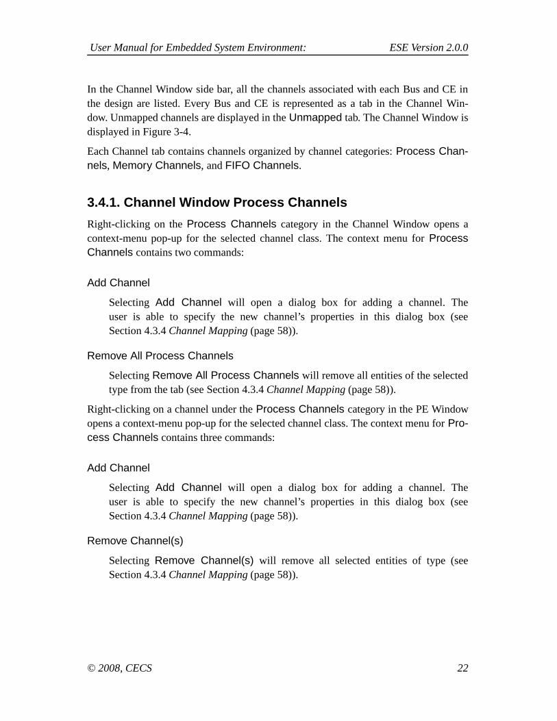
In the Channel Window side bar, all the channels associated with each Bus and CE inthe design are listed. Every Bus and CE is represented as a tab in the Channel Win-dow. Unmapped channels are displayed in the Unmapped tab. The Channel Window isdisplayed in Figure 3-4.
Each Channel tab contains channels organized by channel categories: Process Chan-nels, Memory Channels, and FIFO Channels.
3.4.1. Channel Window Process Channels
Right-clicking on the Process Channels category in the Channel Window opens acontext-menu pop-up for the selected channel class. The context menu for ProcessChannels contains two commands:
Add Channel
Selecting Add Channel will open a dialog box for adding a channel. Theuser is able to specify the new channel’s properties in this dialog box (seeSection 4.3.4 Channel Mapping (page 58)).
Remove All Process Channels
Selecting Remove All Process Channels will remove all entities of the selectedtype from the tab (see Section 4.3.4 Channel Mapping (page 58)).
Right-clicking on a channel under the Process Channels category in the PE Windowopens a context-menu pop-up for the selected channel class. The context menu for Pro-cess Channels contains three commands:
Add Channel
Selecting Add Channel will open a dialog box for adding a channel. Theuser is able to specify the new channel’s properties in this dialog box (seeSection 4.3.4 Channel Mapping (page 58)).
Remove Channel(s)
Selecting Remove Channel(s) will remove all selected entities of type (seeSection 4.3.4 Channel Mapping (page 58)).
© 2008, CECS 22

User Manual for Embedded System Environment: ESE Version 2.0.0
Properties
Selecting Properties will open a properties dialog box for the selected entity fromthe process. The user is able to modify port and route properties in this dialog box.
3.4.2. Channel Window Memory Channels
Right-clicking on the Memory Channels category in the Channel Window opens acontext-menu pop-up for the selected channel class. The context menu for MemoryChannels contains two commands:
Add Channel
Selecting Add Channel will open a dialog box for adding a channel. Theuser is able to specify the new channel’s properties in this dialog box (seeSection 4.3.4 Channel Mapping (page 58)).
Remove All Memory Channels
Selecting Remove All Memory Channels will remove all entities of the selectedtype from the tab (see Section 4.3.4 Channel Mapping (page 58)).
Right-clicking on a channel under the Memory Channels category in the PE Windowopens a context-menu pop-up for the selected channel class. The context menu for eachchannel contains three commands:
Add Channel
Selecting Add Channel will open a dialog box for adding a channel. Theuser is able to specify the new channel’s properties in this dialog box (seeSection 4.3.4 Channel Mapping (page 58)).
Remove Channel(s)
Selecting Remove Channel(s) will remove all selected entities of type (seeSection 4.3.4 Channel Mapping (page 58)).
Properties
Selecting Properties will open a properties dialog box for the selected entity fromthe process. The user is able to modify port, address, and route properties in thisdialog box.
© 2008, CECS 23

User Manual for Embedded System Environment: ESE Version 2.0.0
3.4.3. Channel Window FIFO Channels
Right-clicking on the FIFO Channels category in the Channel Window opens a context-menu pop-up for the selected channel class. The context menu for FIFO Channelscontains two commands:
Add Channel
Selecting Add Channel will open a dialog box for adding a channel. Theuser is able to specify the new channel’s properties in this dialog box (seeSection 4.3.4 Channel Mapping (page 58)).
Remove All FIFO Channels
Selecting Remove All FIFO Channels will remove all entities of the selected typefrom the tab (see Section 4.3.4 Channel Mapping (page 58)).
Right-clicking on a channel under the FIFO Channels category in the PE Windowopens a context-menu pop-up for the selected channel class. The context menu for eachchannel contains two commands:
Add Channel
Selecting Add Channel will open a dialog box for adding a channel. Theuser is able to specify the new channel’s properties in this dialog box (seeSection 4.3.4 Channel Mapping (page 58)).
Remove Channel(s)
Selecting Remove Channel(s) will remove all selected entities of type (seeSection 4.3.4 Channel Mapping (page 58)).
Properties
Selecting Properties will open a properties dialog box for the selected entity fromthe process. The user is able to modify port, mapping, and route properties in thisdialog box.
© 2008, CECS 24

User Manual for Embedded System Environment: ESE Version 2.0.0
3.5. Database Window
Figure 3-5. Database Window.
In the Database Window side bar, all the database items associated with the designare listed. Each component from the database is represented as a tab in the DatabaseWindow. Each component contains a number of categories, which contain a number ofdatabase item types. The database item types can be dragged directly from the DatabaseWindow onto the Design Canvas to create an instance of that type for the design. TheDatabase Window is displayed in Figure 3-5.
3.6. Output Window
Figure 3-6. Output Window.
The Output Window displays the information related to the process of ESE, such aslogged status, diagnostic and error output of background commands. The Output Win-dow is displayed in Figure 3-6. The Output Window contains six tabs: Compile, Sim-ulate, Verify, Analyze, Synthesize and Shell. The Compile tab displays the log mes-
© 2008, CECS 25

User Manual for Embedded System Environment: ESE Version 2.0.0
sages generated during preprocessing and parsing of the design file during Synthe-sis. The Simulate tab displays the log messages generated by the command line toolsspawned by the main application GUI during simulation. The Verify tab displays thelog messages generated by the command line tools spawned by the main applicationGUI during verification. The Analyze tab displays the log messages generated by thecommand line tools spawned by the main application GUI during analysis. The Syn-thesize tab displays the log messages generated by the command line tools spawned bythe main application GUI during synthesis. Finally, the Shell tab contains an instance ofthe interactive ESE shell interpreter.
The Output Window is mainly for informational purposes and doesn’t contain any buttonthat users can click. Only the Shell tab allows to enter ESE commands interactivelyto be executed by the embedded scripting interpreter. In addition, all tabs support acontext menu through which the user can save the contents of the tab to a file, cut, copyand paste text between a tab and other applications, toggle line wrapping, and clearor completely reset the tab. Furthermore, the Shell tab supports history substitution ofpreviously entered commands via Undo and Redo context menu entries.
The Output Window can be detached or docked. Users can drag the window (by its titlebar or handle) to the desired place. If the Output Window is detached, it can be floatingand displayed anywhere on the desktop. If the Output Window is docked, it has to beattached to any of the borders of the Main Window.
3.7. Message BoxesAs a result of certain actions, the ESE application will pop up message box dialogs forfeedback to or input from the user about handling of special situations. Message boxesare used to provide informative messages and to ask simple questions. In general, thereare two types of message boxes: error dialogs and information dialogs.
© 2008, CECS 26

User Manual for Embedded System Environment: ESE Version 2.0.0
3.7.1. Error Dialogs
Figure 3-7. Error dialog.
If the application encounters an abnormal error situation in which user notificationabout the failure of the initiated action is required, an Error dialog will be popped up(Figure 3-7). The Error dialog displays an error message at the top-half of the Error dia-log. At the bottom-half, an Error dialog contains one button: Ok. Clicking Ok will closethe Error dialog and original dialog (if any) that prompted the message. After clicking,the original action that prompted the message is aborted and cancelled.
3.7.2. Information Dialogs
Figure 3-8. Information dialog.
If the application encounters an abnormal situation in which user notification is requiredand the user is given several choices on how to continue, an Information dialog will bepopped up (Figure 3-8). An information message and associated question is displayed atthe top-half of the dialog. The bottom-half of the dialog contains three buttons: Yes, No,and Cancel. Clicking Yes will accept the recommendation and do the correspondingaction. Clicking No will not accept the recommendation and will not do the correspond-ing action but will continue the original action that prompted the message in the first
© 2008, CECS 27

User Manual for Embedded System Environment: ESE Version 2.0.0
place. Finally, clicking Cancel will not do the recommended action and will also cancelthe original action that prompted the message. Clicking one of above three buttons willclose the Information dialog and original dialog (if any) that prompted the message.
© 2008, CECS 28

User Manual for Embedded System Environment: ESE Version 2.0.0
Chapter 4. Functionality
The functionality of ESE can be classified into the following categories: application, filehandling, design-entity handling, and synthesis & simulation,
4.1. Application PreferencesThe main application of ESE supports a set of persistent application preferences. Appli-cation preferences are persistently stored across different invocations of the tool. In fact,application preferences are shared among all tools in the ESE environment, i.e. they arepersistent across invocation of different tools at different times.
Application preferences are stored in both system-wide and user-specific locations (seeSection 4.2.7 Design Settings Editing (page 39)). System-wide application preferencesaffect all users of ESE applications on the system. User-specific application preferences,on the other hand, are stored in a file in the user’s Linux home directory. The applicationfirst reads the system-wide and then the user-specific settings, i.e. user-specific settingscan override (if given) system-wide settings and if no user-specific settings are given,application settings default to the system-wide settings. If no system-wide settings areavailable, compiled-in defaults are used.
Application preferences in general provide the standard settings (paths, etc.) to use bydefault for the different parts of ESE applications.
Application preferences can be edited by the user by selectingMain::Edit−→Preferences.... This will pop-up the Edit Preferences dialog, whichallow users to browse and specify individual settings. At the bottom of the EditPreferences dialog, buttons Ok and Cancel are available. If users click the Ok button,all the edited preferences are saved. If users click the Cancel button, all the editedpreferences are discarded. Either clicking Ok or Cancel button will close Preferencedialog.
© 2008, CECS 29

User Manual for Embedded System Environment: ESE Version 2.0.0
4.1.1. Application Preferences
Figure 4-1. Edit Preferences dialog.
Database preferences define the location of the database EDB file for the Database Win-dows
The Application tab of the Edit Preferences dialog allows for viewing and selecting ofdatabase file path, as well as other include and library paths. The Application tab isshown in Figure 4-1.
Users can type in the file name and path of the database in the Application’s line editboxes. Besides typing in the file name, users can also select the names by using ...buttons next to the edit box. Clicking ... button will pop up a Database Selection dialogdisplayed in Figure Figure 4-2.
© 2008, CECS 30
User Manual for Embedded System Environment: ESE Version 2.0.0
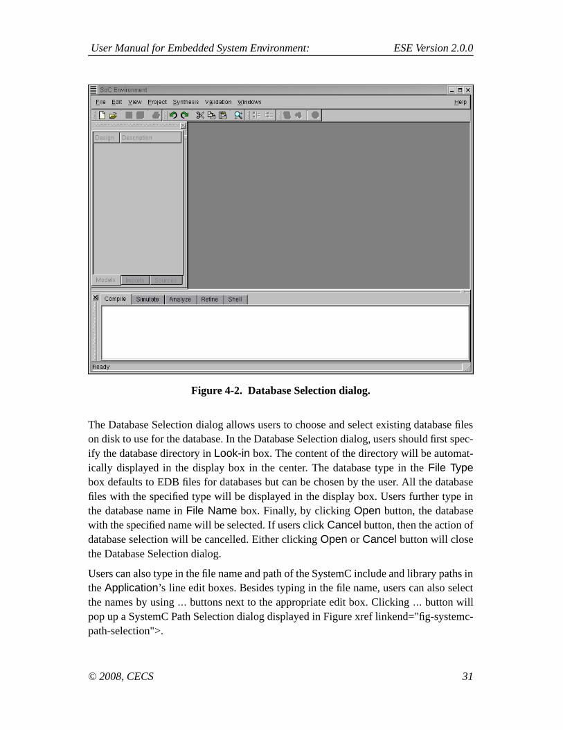
Figure 4-2. Database Selection dialog.
The Database Selection dialog allows users to choose and select existing database fileson disk to use for the database. In the Database Selection dialog, users should first spec-ify the database directory in Look-in box. The content of the directory will be automat-ically displayed in the display box in the center. The database type in the File Typebox defaults to EDB files for databases but can be chosen by the user. All the databasefiles with the specified type will be displayed in the display box. Users further type inthe database name in File Name box. Finally, by clicking Open button, the databasewith the specified name will be selected. If users click Cancel button, then the action ofdatabase selection will be cancelled. Either clicking Open or Cancel button will closethe Database Selection dialog.
Users can also type in the file name and path of the SystemC include and library paths inthe Application’s line edit boxes. Besides typing in the file name, users can also selectthe names by using ... buttons next to the appropriate edit box. Clicking ... button willpop up a SystemC Path Selection dialog displayed in Figure xref linkend="fig-systemc-path-selection">.
© 2008, CECS 31

User Manual for Embedded System Environment: ESE Version 2.0.0
Figure 4-3. SystemC Path Selection dialog.
The SystemC Selection dialog allows users to choose and select a directory on disk touse for the SystemC include path or the SystemC library path. By clicking Openbutton, the directory with the specified name will be selected. If users click Cancelbutton, then the action of database selection will be cancelled. Either clicking Open orCancel button will close the Database Selection dialog.
4.2. Design HandlingDesign handling deals with issues relating to manipulation of design and itscorresponding files within ESE. It allows for tracking of design meta-dataover the whole lifetime of a design. A design contains design-specificsettings that can override or extend application-specific compiler settings (seeSection 4.1 Application Preferences (page 29)). Specifically, a design contains thefollowing information:
Sources
A list of source files. The list of sources contains the union of all C and/or SystemCsource files from which the models that are part of the design have been compiled.For each source file, the location (path) of the file on disk is stored in the design.
© 2008, CECS 32

User Manual for Embedded System Environment: ESE Version 2.0.0
Compiler settings
A set of design-specific options for preprocessing and parsing SystemC source files.Compiler settings contain include paths, import paths, compiler options, and macrodefines and undefines. Design-specific compiler settings generally overwrite or ex-tend the corresponding application-specific settings. In the case of paths, designpaths are prepended to the standard paths defined in the application settings (i.e.they are prepended to the directory search list). In all other cases, options or macrodefines/undefined are appended to the compiler command line after the standardoptions and macros defined in the application settings.
Designs are stored as ESE Data Structure (EDS, *.eds) files on disk. The design fileformat is the same for all tools in the ESE environment, i.e. a design file can be read,modified and written by any ESE tool.
Design can be read from and saved as design files at any time in the ESE application.At any time, however, at maximum only one design can be open and loaded. While acertain design is open and loaded, its settings apply to all actions performed during thattime. In addition, certain actions will automatically update and add data in the currentlyopened and loaded design.
Note: All paths in the design settings are defined to be relative to the location ofthe design file, i.e. relative paths in a design file are converted into absolute pathsby appending the design file’s directory during loading/opening of a design file.During saving/writing of design files, absolute paths are in turn converted back torelative paths if they point to a location below the target design file directory.
In order to deal with management of design files, ESE supports a set of filehandling functions. Design handling includes opening, saving, and closingof design files on disk. Design handling is closely related to Design Canvas(Section 3.2 Design Canvas (page 12)) and Design Canvas Management(Section 4.7 Window Management (page 69)). In general, there is a one-to-oneassociation between design models, design files on disk and design canvases in theWorkspace. Each Design Canvas represents a view onto one loaded design filewhich in turn stores the data of one design model, and vice versa. For example,both file closing (Section 4.2.5 Design Closing (page 37)) and window closing(Section 4.7 Window Management (page 69)) will close the design file and the DesignCanvas and unload the design from ESE’s memory.
© 2008, CECS 33
User Manual for Embedded System Environment: ESE Version 2.0.0
Specifically, file handling consists of the following tasks:
1. Design Creation to create a new design (seeSection 4.2.1 Design Creation (page 34)).
2. Design Opening to open and load existing design files from disk (seeSection 4.2.2 Design Opening (page 34)).
3. Design Saving to save the current design on disk (seeSection 4.2.3 Design Saving (page 36)).
4. Design Closing to close the current design (seeSection 4.2.5 Design Closing (page 37)).
5. Design Reloading to reload the current design’s last saved instance (seeSection 4.2.4 Design Reloading (page 37)).
6. Design Exporting to create a compressed archive file of the current design (seeSection 4.2.6 Design Exporting (page 38)).
7. Design Settings to display and edit the settings of the opened design (seeSection 4.2.7 Design Settings Editing (page 39)).
8. ESE Exiting to exit the ESE application (see Section 4.2.9 ESE Exiting (page 41)).
4.2.1. Design Creation
Users can create a new design by selecting Main::File−→New.... This action will clearall windows (Design Canvas, PE, Channel and Database Windows) in preparation for anew design.
Error/Information Messages: Assuming before design creation, users have opened an-other design in ESE, the currently opened design has been modified and the openeddesign is not saved yet. When users select Main::File−→New, an Information dia-log will be popped up querying whether to save the current design first before creat-ing a new one. If the users accept the recommendation, a Design Saving action (seeSection 4.2.3 Design Saving (page 36)) is performed first. In case of errors creating thedesign file (file errors, wrong file format), an error dialog with a corresponding errormessage is popped up. Upon confirming the error, the file creating action is cancelled.
© 2008, CECS 34

User Manual for Embedded System Environment: ESE Version 2.0.0
4.2.2. Design Opening
Figure 4-4. Design Open dialog.
Operation: Users can open an existing design file on disk by selectingMain::File−→Open.... The Design Open dialog window will pop up in which userscan choose and select an existing file on disk to open and load. The Design Open dialogis illustrated in Figure 4-4.
Users should first specify the directory of the file in Look-in box. The content of thedirectory will be automatically displayed in the display box in the center. The file typedefaults to EDS files (*.eds). All the files with the specified type will be displayed inthe display box. Users then further select the file name in the File Name box. Finally,by clicking the Open button, the file with the specified name will be open. If users clickthe Cancel button, the action of file opening will be cancelled. Either clicking Open orCancel button will close the File Open dialog.
Opening and loading a design file will result in a corresponding design appearing in theDesign Canvas.
Error/Information Messages: If the specified design file does not exist before clickingOpen button, then clicking Open button has no effect.
In case of errors reading the design file from disk (file errors, wrong file format), an errordialog with a corresponding error message is popped up. Upon confirming the error, theDesign Opening action is cancelled.
© 2008, CECS 35
User Manual for Embedded System Environment: ESE Version 2.0.0
Assuming before design opening, users have opened another design in ESE, the openeddesign is modified and the opened design is not saved yet. When users open a differentdesign, the Information dialog will be popped up to recommend users to save the previ-ous design first and, if the recommendation is accepted, a Design Saving action will beperformed. This is the same as the case in task Section 4.2.1 Design Creation (page 34).
4.2.3. Design Saving
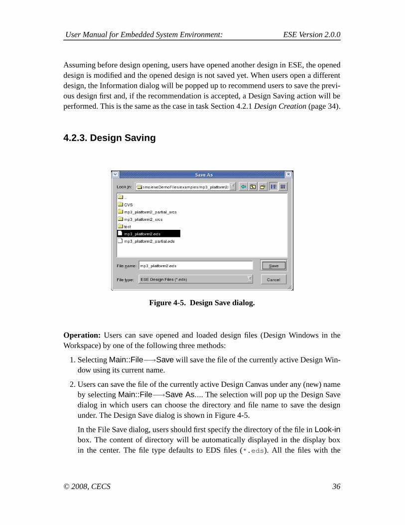
Figure 4-5. Design Save dialog.
Operation: Users can save opened and loaded design files (Design Windows in theWorkspace) by one of the following three methods:
1. Selecting Main::File−→Save will save the file of the currently active Design Win-dow using its current name.
2. Users can save the file of the currently active Design Canvas under any (new) nameby selecting Main::File−→Save As.... The selection will pop up the Design Savedialog in which users can choose the directory and file name to save the designunder. The Design Save dialog is shown in Figure 4-5.
In the File Save dialog, users should first specify the directory of the file in Look-inbox. The content of directory will be automatically displayed in the display boxin the center. The file type defaults to EDS files (*.eds). All the files with the
© 2008, CECS 36

User Manual for Embedded System Environment: ESE Version 2.0.0
specified type will be displayed in the display box. Users then further select the filename in File Name box. Finally, by clicking Save button, the current opened filewill be saved as the file with the specified name. If users click Cancel button, thenthe action of file saving will be cancelled. Either clicking Save or Cancel buttonwill close the Design Save dialog.
Error/Information Messages: When selecting Main::File−→Save As... and specify-ing the file name of an existing design file on disk, an Information dialog will pop upasking whether to overwrite the existing file. If the users decline this, the design savingaction will be cancelled.
When selecting Main::File−→Save or Main::File−→Save As..., errors may occur (fileerrors, e.g. if no space is available on the disk). In this case, an Error dialog as shown inFigure 3-7 will be popped up, corresponding error messages will be displayed, and thedesign saving action will be cancelled.
4.2.4. Design Reloading
Operation: Users can save reload the current design file (Design Windows in theWorkspace) by the following method:
1. Selecting Main::File−→Reload... will save the file of the currently active DesignWindow using its current name.
Error/Information Messages: When selecting Main::File−→Reload..., errors mayoccur (file errors, e.g. if no space is available on the disk). In this case, an Error di-alog as shown in Figure 3-7 will be popped up, corresponding error messages will bedisplayed, and the design saving action will be cancelled.
4.2.5. Design Closing
Operation: Users can close the file and window of the currently active Design Windowin the Workspace by selecting Main::File−→Close. Closing a file will unload the designfrom memory and will close the corresponding Design Canvas in the Workspace.
Error/Information Messages: If the current design is modified and not yet saved,selecting Close will pop up an Information dialog which recommends to save the
© 2008, CECS 37

User Manual for Embedded System Environment: ESE Version 2.0.0
current design first. If the users accept the recommendation, a design saving action(Section 4.2.3 Design Saving (page 36)) is performed before closing the design.
4.2.6. Design Exporting
Figure 4-6. Design Export dialog.
Operation: Users can export opened and loaded design files (Design Window) as com-pressed archive file (*.tbz) on disk by selecting Main::File−→Export.... The selectionwill pop up the Design Export dialog in which users can choose the directory and filename to save the design under. The Design Export dialog is shown in Figure 4-6.
In the Design Export dialog, users should first specify the directory of the file in Lookin box. The content of directory will be automatically displayed in the display box in thecenter. The file type defaults to ESE Exported Design Files (*.tbz). All the files withthe specified type will be displayed in the display box. Users then further select the filename in File Name box. Finally, by clicking Save button, the current opened file willbe exported to the file with the specified name. If users click Cancel button, then theaction of design exporting will be cancelled. Either clicking Save or Cancel button willclose the File Export dialog.
Error/Information Messages: When selecting Main::File−→Export... and specifyingthe file name of an existing file on disk, an Information dialog will pop up asking whetherto overwrite the existing file. If the users decline this, the file exporting action will becancelled.
© 2008, CECS 38
User Manual for Embedded System Environment: ESE Version 2.0.0
When writing files to disk, errors may occur (file errors, e.g. if no space is available onthe disk). In this case, an Error dialog will be popped up, corresponding error messageswill be displayed, and the file exporting action will be cancelled.
4.2.7. Design Settings Editing
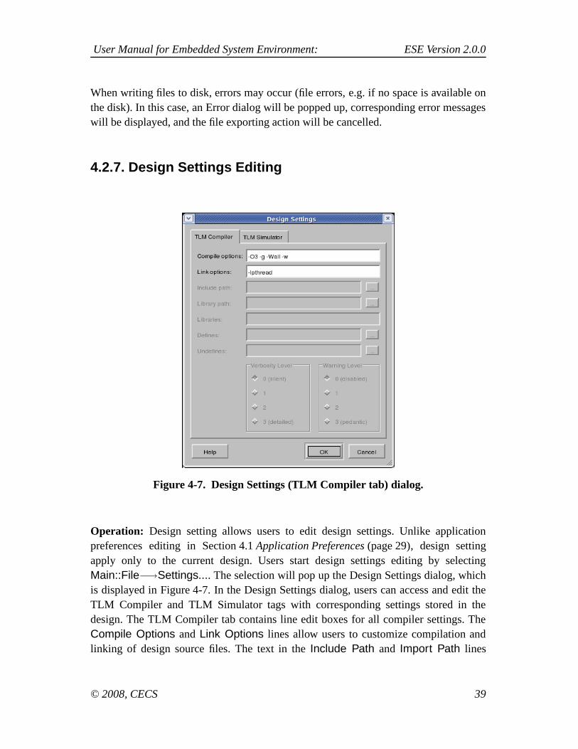
Figure 4-7. Design Settings (TLM Compiler tab) dialog.
Operation: Design setting allows users to edit design settings. Unlike applicationpreferences editing in Section 4.1 Application Preferences (page 29), design settingapply only to the current design. Users start design settings editing by selectingMain::File−→Settings.... The selection will pop up the Design Settings dialog, whichis displayed in Figure 4-7. In the Design Settings dialog, users can access and edit theTLM Compiler and TLM Simulator tags with corresponding settings stored in thedesign. The TLM Compiler tab contains line edit boxes for all compiler settings. TheCompile Options and Link Options lines allow users to customize compilation andlinking of design source files. The text in the Include Path and Import Path lines
© 2008, CECS 39
User Manual for Embedded System Environment: ESE Version 2.0.0
defines the directory lists (separated by colons “:”) for the project-specific includeand import paths, respectively. The text in the Defines and Undefines lines definethe list of macro defines and undefines (separated by semicolons “;”), respectively.The text in the Options line defines the project’s compiler options/switches. Finally,Verbosity Level and Warning Level define verbosity level and warning level so thatall tasks performed are logged and warning messages are enabled, respectively.See Section 4.1 Application Preferences (page 29) for more details about compilersettings. Similarly, the TLM Simulator tab includes the following options for outputdisplay of simulation (Output): No terminal, Terminal window, or outputting in theExternal console defined by users. Further, users can enable simulation logging bychecking the appropriate check-box. Finally, line edit boxes Simulation Options andPost-simulation command define directives to the simulation engine during and afterTLM simulation.
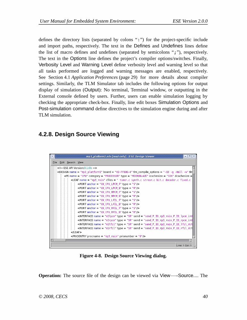
4.2.8. Design Source Viewing
Figure 4-8. Design Source Viewing dialog.
Operation: The source file of the design can be viewed via View−→Source.... The
© 2008, CECS 40

User Manual for Embedded System Environment: ESE Version 2.0.0
result of View−→Source... is shown in Figure 4-8.
4.2.9. ESE Exiting
Operation: Selecting Main::File−→Exit will exit the ESE application and close theESE GUI.
Error/Information Messages: If there is an open Design Canvas that is modified andnot yet saved, an Information dialog will pop up querying whether to save the corre-sponding design. The users will be able to cancel the whole exit action via the corre-sponding dialog button. If the users accept the recommendation to save the file, a filesaving action will be triggered (see Section 4.2.3 Design Saving (page 36)). Note thatthe design saving action can trigger additional Error dialogs which in turn can abort thewhole exit operation in case of file errors during saving.
4.3. Transaction Level ModelingTransaction Level Modeling is a process of implementing a system specification on aplatform consisting of PEs and memories interconnected with busses and CEs (bridges,transducers), in order to generate a respective transaction level model (TLM) of the de-sign. During TL Modeling, the designers allocate PEs and memories, busses and CEsand connect them into an intergral system platform. During mapping, the designers mapcomputation processes to the PEs and end-to-end communication channels to the net-work of PEs, CEs and busses. Processes are units of computation in the specification.The end-to-end channels connect processes to enable interprocess data exchange, or con-nect a process with the memory for data storing. Specifically, Transaction Level Model-ing consists of the following tasks:
1. PE Allocation to allocate and select PEs/memories from the PEdatabase in order to assemble the system’s computing architecture (seeSection 4.3.1 PE Allocation (page 42)).
2. PE Mapping to map the design’s computation entities (or processes) to the selectedPEs (see Section 4.3.2 PE Mapping (page 45)).
3. Network Allocation to allocate, select and define the communication network topol-ogy (see Section 4.3.3 Network Allocation (page 49)).
© 2008, CECS 41

User Manual for Embedded System Environment: ESE Version 2.0.0
4. Channel Mapping to map the design’s global, system-level channels to the selectednetwork of PEs, busses and CEs (see Section 4.3.4 Channel Mapping (page 58)).
5. TLM synthesis to automatically generate an Transaction Level Model from thegiven specification based on the decision made during the allocation of componentsand application-to-platform mapping (see Section 4.4 TLM Synthesis (page 63)).
In order to perform TL Modeling, not all the tasks described in previous sections needto be done. However, some tasks must be executed and must be executed in a certainorder. These mandatory tasks and their execution sequence are:
1. Design Creation or Design Opening.
2. Preferences Editing and Design Settings Editing.
3. PE Allocation.
4. PE Mapping.
5. Network Allocation.
6. Channel Mapping.
7. TLM Synthesis.
8. Design Saving and/or ESE Exiting.
Note that steps 3 through 7 can be performed repeatedly in a loop in order to generatemultiple candidate TL models in one design modeling session.
© 2008, CECS 42

User Manual for Embedded System Environment: ESE Version 2.0.0
4.3.1. PE Allocation
Figure 4-9. PE Allocation result.
Users can select PEs/memories out of the PE database in order to allocate and assemblethe system architecture. PE allocation information is stored in the design itself (*.eds)as an annotated Data Structure component.
© 2008, CECS 43

User Manual for Embedded System Environment: ESE Version 2.0.0
Figure 4-10. PE Parameters dialog.
Operation: In order to do PE allocation, users first select Processing tab in the DatabaseWindow. The Processing tab contains the PE category table, with each row represent-ing one category of PEs in the database. For example, row SW Processors containsall the general-purpose processors in the database. The supported EDS categories areHardware IPs, Custom Hardware or SW Processor. The users add the PE to the design’splatform by dragging the desired EDS component from its category and dropping it intothe Design Canvas. This creates a PE in the Design Canvas with the default PE_name.The result of a PE Allocation action is shown in Figure 4-9.
In the PE Window, list of tabs with currently allocated PEs will be shown (Figure 4-9).Each tab lists the names of Processes, Memories and Channels belonging to that PE.
PEs can be parametrized after instantiation by right-clicking on the component in theDesign Canvas. The Component Parameter dialog will be popped up (see Figure 4-10).In this dialog, the users can enter and confirm all parameters for the given componentinstance to be allocated. Users can enter any value for any parameter (within the value
© 2008, CECS 44

User Manual for Embedded System Environment: ESE Version 2.0.0
range allowed by the component) by clicking into each parameter’s value field in thedialog. Clicking the Ok button of the dialog will generate a new customized compo-nent type with the selected parameters and will then allocate a new instance of thisparametrized type. Clicking the Cancel button aborts component parametrization.
In order to remove a PE from the design’s platform, users can right-click on the targetPE to be removed in the Design Canvas and select the Remove PE option. Clicking onthe Remove PE will remove the selected PE from the list of allocated PEs.
Error/Information Messages: During PE editing, if users try to give PEs a name whichis already used as the name of another PE in the design, an Error dialog will be poppedup with a corresponding error message and a query to continue without saving changes.Answering ’no’ will close the Error dialog. Answering ’yes’ will abort and cancel thePE Parameters editing operation.
During PE adding, when adding a PE, the selected PE type is read from the database.In case of errors during database opening (e.g. file errors or wrong file format), an Errordialog will be popped up and the PE adding operation will be aborted.
4.3.2. PE Mapping
In order to implement the computation in the design model on the allocated computationarchitecture consisting of PEs and memories, users have to be able to map the processes,variables (memory) and channels in the specification onto the allocated PEs. Hence,mapping consists of separate process mapping, memory mapping, and channel mappingtasks.
4.3.2.1. Process Mapping
Process mapping allows for mapping of process types/classes in the design onto al-located PEs, i.e. process mapping information is stored as annotations at the processclasses in the design. A process is mapped to the PE by right-clicking on the corre-sponding PE tab in the PE Window and selecting Add Process option. This creates aprocess listing in the PE tab with the default process name. Process mapping informa-tion consists of proces name, source files and process ports and it can be accessed forediting with right-clicking on the process listing.
© 2008, CECS 45

User Manual for Embedded System Environment: ESE Version 2.0.0
Process Renaming
Figure 4-11. Process Renaming dialog.
Process renaming is accessed by right-clicking on the process listing and selectingRename Process option. The process name line box can be edited until key Enter ispressed. Process renaming is shown in Figure 4-11.
Adding Source File(s) to the Process
Figure 4-12. Adding Sources to a Process (C File) dialog.
© 2008, CECS 46

User Manual for Embedded System Environment: ESE Version 2.0.0
The users can add source files (*.c and *.h) to the process by right-clicking on theprocess listing and selecting Add .C File(s) and Add .H File(s) options, respectively.An Open dialog will be popped up (see Figure 4-12). In this dialog, users shouldfirst specify the file(s) directory in Look-in box. The content of the directory will beautomatically displayed in the display box in the center. The file(s) type in the FileType box defaults to C source files (*.c) or C header files (*.h), depending on theselected option. All the source/header files with the specified type will be displayedin the display box. Users further type in the file name(s) in File Type box. Finally,by clicking Open button, the file(s) with the specified name(s) will be selected. Ifusers click Cancel button, then the action of database selection will be cancelled.Either clicking Open or Cancel button will close the Open dialog.
Viewing Source File(s) of the Process
Figure 4-13. Adding Sources to a Process (C File) dialog.
© 2008, CECS 47

User Manual for Embedded System Environment: ESE Version 2.0.0
The users can view the source file(*.c and *.h) of the process by right-clickingon the process listing and selecting View Source. An ESE Design Viewer dialogwill be popped up (see Figure 4-13). In this dialog, users can view the source filetextually and search for keywords. Choosing Main::File−→Close will close theESE Design Viewer dialog.
Adding Process Port(s) to the Process
Figure 4-14. Adding a Process Port to a Process dialog.
The users add process ports to the process by right-clicking on the process listingand selecting Add Process Port option. An Add Process Port dialog will be poppedup, as shown in Figure 4-14. The users can name the process port in Name line box,and define its type by selecting one option in the Type drop box. Upon selection,the API box will automatically display the selected type(s) of API(s). The userscan then name the API(s) belonging to that port by double-clicking and writing theAPI functions in the appropriate lines of the display box. Finally, by clicking Addbutton, the process port with the specified API(s) will be selected. If users clickCancel button, then the action of creating a process port will be cancelled. Eitherclicking Open or Cancel button will close the Add Process Port dialog.
© 2008, CECS 48

User Manual for Embedded System Environment: ESE Version 2.0.0
4.3.2.2. Local Memory Mapping
Memory mapping allows for mapping of variable instances in the design into exposedmemories of allocated regular PEs. An exposed memory is added to the PE by right-clicking on the corresponding PE tab in the PE Window and selecting Add ExposedMemory option. This creates a memory listing in the PE tab with the default memoryname. Memory mapping information consists of memory name and size and it can beaccessed for editing with right-clicking on the memory listing.
4.3.2.3. Local Channel Mapping
Channel mapping attributes an end-to-end channel to a pair of processes. Dependingon the selected route, a channel can be either local (i.e. belonging to a singlePE), or global (i.e. connecting processes of different PEs), mapped to the networkof busses and CEs. Local and global channel mapping is uniformly described inSection 4.3.4 Channel Mapping (page 58).
4.3.3. Network Allocation
Network allocation and connection information is stored in the design itself (*.eds) asan annotated Data Structure allocation and connection tables.
Network topology includes an interconnection of communication busses and commu-nication elements (CEs). The end-to-end channels that implement communication be-tween processes are then mapped to the routes of busses and CEs connecting thoseprocesses. Hence, network allocation consists of separate bus allocation, CE allocation,network connecting and channel mapping tasks.
© 2008, CECS 49

User Manual for Embedded System Environment: ESE Version 2.0.0
4.3.3.1. Bus Allocation
Figure 4-15. Bus Allocation result.
Operation: In order to allocate a bus, users first select Communication tab in theDatabase Window. The Communication tab contains the communication categorytable, with each row representing one category of communication media in thedatabase. For example, category Bus includes all busses supported with the database.The EDS communication categories are Network, Bus and Link. The user adds thecommunication component to the design’s platform by dragging the desired EDScomponent from its category and dropping it into the Design Canvas. This creates a busin the Design Canvas with the default Bus_name. The result of a Network Allocation(adding a bus) action is shown in Figure 4-15.
In the Channel Window, list of tabs with currently allocated busses will be shown(Figure 4-15). Each tab lists the names of Process Channels, Memory channels and FIFO
© 2008, CECS 50
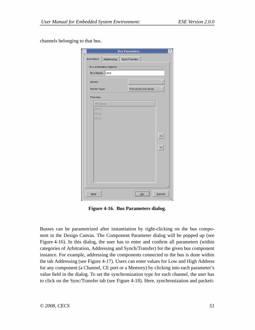
User Manual for Embedded System Environment: ESE Version 2.0.0
channels belonging to that bus.
Figure 4-16. Bus Parameters dialog.
Busses can be parametrized after instantiation by right-clicking on the bus compo-nent in the Design Canvas. The Component Parameter dialog will be popped up (seeFigure 4-16). In this dialog, the user has to enter and confirm all parameters (withincategories of Arbitration, Addressing and Synch/Transfer) for the given bus componentinstance. For example, addressing the components connected to the bus is done withinthe tab Addressing (see Figure 4-17). Users can enter values for Low and High Addressfor any component (a Channel, CE port or a Memory) by clicking into each parameter’svalue field in the dialog. To set the synchronization type for each channel, the user hasto click on the Sync/Transfer tab (see Figure 4-18). Here, synchronization and packeti-
© 2008, CECS 51

User Manual for Embedded System Environment: ESE Version 2.0.0
zation options are set per channel.
Figure 4-17. Bus Addressing dialog.
© 2008, CECS 52

User Manual for Embedded System Environment: ESE Version 2.0.0
Figure 4-18. Bus Synchronization dialog.
Clicking the Ok button of the dialog will generate a new customized component typewith the selected parameters and will then allocate a new instance of this parametrizedtype. Clicking the Cancel button aborts component parametrization.
In order to remove a bus from the design’s platform, users can right-click on the targetbus to be removed in the Design Canvas and select the Remove Bus option. Clicking onthe Remove Bus will remove the selected Bus and all its connections from the platform.
Error/Information Messages: During bus editing, if users try to give busses a namewhich is already used as the name of another bus in the design, an Error dialog will bepopped up with a corresponding error message and a query to continue without savingchanges. Answering ’no’ will close the Error dialog. Answering ’yes’ will abort andcancel the Bus Parameters editing operation.
© 2008, CECS 53

User Manual for Embedded System Environment: ESE Version 2.0.0
When adding a bus, the selected bus type is read from the database. In case of errorsduring database opening (e.g. file errors or wrong file format), an Error dialog will bepopped up and the PE adding operation will be aborted.
4.3.3.2. CE Allocation
Figure 4-19. CE Allocation result.
Operation: In order to allocate a CE, users first select CE tab in the Database Window.The CE tab contains the CE category table, with each row representing one category ofCEs in the database. For example, category Bridge includes all bridges supported withthe database. The EDS communication categories are Router, Transducer and Bridge.The user adds the CE component to the design’s platform by dragging the desired EDScomponent from its category and dropping it into the Design Canvas. This creates a CE
© 2008, CECS 54

User Manual for Embedded System Environment: ESE Version 2.0.0
in the Design Canvas with the default CE_name. The Network Allocation (adding a CE)is shown in Figure 4-19.
In the Channel Window, list of tabs with currently allocated CEs will be shown(Figure 4-19). Each tab lists the names of Process Channels, Memory channels andFIFO channels belonging to that CE.
Figure 4-20. CE Parameters dialog.
© 2008, CECS 55

User Manual for Embedded System Environment: ESE Version 2.0.0
Figure 4-21. CE Scheduling dialog.
CEs can be parametrized after instantiation by right-clicking on the CE component in theDesign Canvas. The Component Parameter dialog will be popped up (see Figure 4-20).In this dialog, the user has to enter and confirm all parameters (within categories ofFIFO and Scheduling) for the given bus component instance. Users can enter any valuefor any parameter (within the value range allowed by the component) by clicking intoeach parameter’s value field in the dialog. There are two tabs = Fifo and Scheduling. Inthe Fifo tabe, the size and partition types are set. In the Scheduling tab (see Figure 4-21),the transducer scheduling policy is set. Clicking the Ok button of the dialog will generatea new customized component type with the selected parameters and will then allocate anew instance of this parametrized type. Clicking the Cancel button aborts componentparametrization.
In order to remove a CE from the design’s platform, users can right-click on the targetcomponent to be removed in the Design Canvas and select the Remove CE option.Clicking on the Remove CE will remove the selected CE and all its connections fromthe platform.
Error/Information Messages: During CE editing, if users try to give CEs a name whichis already used as the name of another CE in the design, an Error dialog will be poppedup with a corresponding error message and a query to continue without saving changes.Answering ’no’ will close the Error dialog. Answering ’yes’ will abort and cancel theCE Parameters editing operation.
© 2008, CECS 56

User Manual for Embedded System Environment: ESE Version 2.0.0
When adding a CE, the selected CE type is read from the database. In case of errorsduring database opening (e.g. file errors or wrong file format), an Error dialog will bepopped up and the PE adding operation will be aborted.
4.3.3.3. Connecting the network
The network is constructed by connecting PEs and CEs to the busses. This process isdone with the following operations:
Port Adding
Figure 4-22. Port Adding dialog.
By right-clicking onto a PE or CE in the Design Canvas and selecting Add Portoption, the user attributed the communication port to that PE/CE. The Port Addingis shown in Figure 4-22.
Remove Port
Right-clicking onto a PE’s or CE’s port and selecting the Remove Port from thecontext menu will remove that port from the corresponding PE or CE.
© 2008, CECS 57

User Manual for Embedded System Environment: ESE Version 2.0.0
Connecting to the Bus
Figure 4-23. Connecting to the bus dialog.
Users can connect the PE/CE to the bus (named Bus_name) by right-clicking onthe created PE/CE’s port and selecting Connect toBus_name option. Generally,PE/CE ports can connected to busses either as bus master (M), bus slave (S) or ascombined bus master/slave (MS). as shown in Figure 4-23.
4.3.4. Channel Mapping
Figure 4-24. Add Channel context menu.
© 2008, CECS 58

User Manual for Embedded System Environment: ESE Version 2.0.0
Channel mapping attributes an end-to-end channel to a pair of processes. Creating achannel begins by right-clicking onto a Channel Window and selecting Add Chan-nel option. This action is shown on in Figure 4-24. The Channel Type dropbox allowsthe users to select among the following types of channels: Process-to-Process Channel,Memory Channel and FIFO Channel.
Process-to-Process Channel
Figure 4-25. Process-to-Process Channel dialog.
Process-to-Process Channel is defined with the inputting the values of the follow-ing parameters, as shown in Figure 4-25:
1. Name line box defines a unique name identifier for the channel.
2. Dropbox Direction provides options of Unidirectional and Bidirectional chan-nel. Unidirectional channels only transfer data from Process 1 to Process2.
3. If the channel is defines as Unidirectional, dropbox Process 1 allows the usersto select the sending process. Otherwise, it defines the first process in the com-municating process pair.
© 2008, CECS 59

User Manual for Embedded System Environment: ESE Version 2.0.0
4. Dropbox Process Port provides the users with the list of available ports of theselected process. Available ports have no previously assigned channels to themand are, if the channel is Unidirectional, defined as sending or writing ports.
5. Similarly to Process 1, dropbox Process 2 defines either process receiver,or the second process in the communicating process pair.
6. Process Port lists previously unassigned ports of the selected process. If thechannel is Unidirectional, the listed ports are defined as receiving or readingports.
7. Finally, two dropboxes for routing give the users the list of available routesbetween processes. If the channel is Unidirectional, only one of the dropboxesis active.
Memory Channel
Figure 4-26. Memory Channel dialog.
Memory Channel is a channel that connects a process with the Memory element.The channel is defined with the following parameters, as shown in Figure 4-26:
© 2008, CECS 60
User Manual for Embedded System Environment: ESE Version 2.0.0
1. Name line box defines a unique name identifier for the channel.
2. Dropbox Direction allows users to define a channel as: Read only, Write onlyor Read/write channel.
3. Users can select the process that accesses the Memory from the list of pro-cesses presented in the dropbox Process.
4. Dropbox Process Port provides the users with the list of available ports of theselected process. Available ports have no previously assigned channels to themand are defined as reading and/or writing ports (depending on the selection inchannel Direction).
5. Users can define the Memory that Process reads from and/or writes into byselecting from the dropbox Memory. Only memories accessable (i.e. exposed)to the channel are listed here.
6. Low Address and High Address line boxes allow the user to define the ad-dress range of the Memory that is accessable to the Process via this channel.
7. Finally, two dropboxes for routing give the users the list of available routesbetween a Process and a Memory. If the channel is Read only, the dropboxMemory->Process is the only one active for selection. If the channel is Writeonly, the active dropbox is Process->Memory.
© 2008, CECS 61

User Manual for Embedded System Environment: ESE Version 2.0.0
FIFO Channel
Figure 4-27. FIFO Channel dialog.FIFO Channel is defined with the following parameters, as shown in Figure 4-27.
1. Name line box defines a unique name identifier for the channel.
2. Next, the line box Size defines the storage capacity of the FIFO channel. (i.e.the depth of the FIFO queue).
3. The sending process is defined with selection from the dropbox Writer, andthe corresponding (i.e. writing) process port can be selected from the dropboxPort.
4. Similarly, the reading process is defined by selecting from the dropboxReader, with the dropbox Port defining its (reading) port.
5. Mapping line box allows the user to define whether the FIFO will be mappedto the WRITER PE or READER PE.
6. Finally, the dropbox Route gives the users the list of available routes betweentwo processes. Since FIFO channel is by definition unidirectional, only one
© 2008, CECS 62

User Manual for Embedded System Environment: ESE Version 2.0.0
dropbox defines the route.
Reviewing Channel Properties
After creating a channel, users can access channel properties by right-clicking onthe listing of the channel whose properties they wish to review and selecting Proper-ties option. Channel listings Process Channels, Memory Channels and FIFO Chan-nels for are located in the Channel Window.
Removing a Channel
Users can remove created channels by right-clicking on the channel listing in theChannel Window and selecting Remove Channel option. This action releases allthe ports that were assigned to the removed channel.
In order to add a defined channel to the design, users can edit the listed channel pa-rameters and click the Add button. If users click Cancel button, then all unsaved userselections will be cancelled. Either clicking the Add or Cancel button will close theAdd Channel dialog.
Every channel connected to a system bus must be assigned an address range. Base ad-dresses and address masks define the address space occupied by the channel on the bus,i.e. they define the address decoding to be performed for that channel. Note that addressranges will later be used for automatic address selection during bus parameter assign-ment. The addresses of channels mapped to the same bus must not overlap.
Error/Information Messages: There are several errors that can happen during bus orCE allocation:
1. When adding a bus or CE to the allocation via the Bus or CE Selection dialog, theselected bus/CE type is read from the database. In case of database read errors (fileerrors, database format errors) during this operation, an Error dialog will be poppedup and the Bus/CE Adding operation aborted.
2. In addition, if during port name editing users try to give ports a name which isalready used as the name of another port of the same PE/CE, a corresponding Errordialog will be shown and the renaming operation is cancelled.
© 2008, CECS 63

User Manual for Embedded System Environment: ESE Version 2.0.0
4.4. TLM Synthesis
4.4.1. Generate Functional TLM
Generation of the functional TLM includes generating SystemC code for the createddesign, compiling and linking the design files into an executable tlm binary. The codegeneration is started by selecting Main::Synthesis−→Generate Timed TLM optionin the main menu.
4.4.2. Generate TLM
Generation of the timed TLM includes generating SystemC code annotated with the es-timated values of execution time for computation and communication, compiling andlinking the design files into an executable tlm. The code generation is initiated by se-lecting Main::Synthesis−→Generate Timed TLM.
4.5. TLM Validation
4.5.1. Simulate Functional TLM
Simulation of the functional TLM is started by selecting Main::Validation−→SimulateFunctional TLM. This will pop-up the Simulation Output Window dialog, which allowusers to validate the correctness of the functional TLM execution.
4.5.2. Simulate Timed TLM
Simulation of the timed TLM is started by selecting Main::Validation−→SimulateTimed TLM. This will pop-up the Simulation Output Window dialog, which allow usersto validate the correctness of the timed TLM execution.
4.6. Performance AnalysisFollowing a successful timed TLM simulation, users can access and analyze the esti-
© 2008, CECS 64

User Manual for Embedded System Environment: ESE Version 2.0.0
mated performance of the created design at the transaction level of communication. Thetotal cycles for the system simulation is shown in the output terminal, and it is also recor-den in the file {project_name}.cyc. The performance of PEs, CEs and bus componentsin the design model can be reviewed by right-clicking on the component of interest inthe Design Canvas and selecting the View Graph... option.
4.6.1. PE Performance Analysis
Figure 4-28. PE Performance Analysis dialog.
© 2008, CECS 65

User Manual for Embedded System Environment: ESE Version 2.0.0
Figure 4-29. PE Computation graph dialog.
Figure 4-30. Process Computation graph dialog.
PE Performance Analysis graph is accessed with right-clicking on that PE in the De-sign Canvas and selecting View Graph... option. This action pops-up a pie chart of theselected PE’s performance, divided into the categories of idle time, Real-Time Oper-ating System (RTOS) overhead time, time spent on communication and time spent oncomputation (idle, RTOS, comm, comp, respectively). The PE performance pie chart isshown in Figure 4-28. By clicking on the computation slice, another pie chart is shown(see Figure 4-29). It displays the processes slice in the PE computation time. By further
© 2008, CECS 66

User Manual for Embedded System Environment: ESE Version 2.0.0
clicking on a process, the user can see the different functions which compose the pro-cess (see Figure 4-30). The pie chart can be customized by accessing Main::Customizemenu. The available options in viewing the performance graph are as follows:
No Explode / Medium Explode / Heavy Explode
No Explode is a default option for viewing a pie chart, which differentiates theseperate slices of the pie by color alone. Users can emphasize the separation be-tween pie slices by selecting Medium or Heavy Explode, which, in addition to useof color, injects extra space between pie slices.
Quantifying PE Performance
PE’s performance in terms of idle time and times spent on communication andcomputation can be quantified with a ratio, their absolute values (in clock cycles),percentage values or with their respective idle/comm/comp labels.
Closing Performance Analysis Window
The pie chart window is closed by selecting Main::Window−→Close menu.
4.6.2. Bus Performance Analysis
Figure 4-31. Bus Performance Analysis dialog.
© 2008, CECS 67

User Manual for Embedded System Environment: ESE Version 2.0.0
Figure 4-32. Bus Data Transfer Analysis dialog.
Bus Performance Analysis graph is accessed with right-clicking on the desired bus inthe Design Canvas and selecting View Graph... option. This action pops-up a pie chartof the selected bus’ performance, divided into the categories of idle time, time spent onfetching instruction/data (if the Program/Data is stored in the external memory) and timespent on transferring messages between processes (idle, Program/Data, data transfer,respectively). The bus performance pie chart is shown in Figure 4-31. By clicking onthe Data Transfer slice, the breakdown of the data transfer by channels is shown (seeFigure 4-32). The pie chart can be customized by accessing Main::Customize menu.The available options in viewing the performance graph are as follows:
No Explode / Medium Explode / Heavy Explode
No Explode is a default option for viewing a pie chart, which differentiates theseperate slices of the pie by color alone. Users can emphasize the separation be-tween pie slices by selecting Medium or Heavy Explode, which, in addition to useof color, injects extra space between pie slices.
Quantifying Bus Performance
The bus performance in terms of idle time and times spent on fetching program in-
© 2008, CECS 68

User Manual for Embedded System Environment: ESE Version 2.0.0
structions/data and data transfer can be quantified with a ratio, their absolute values(in clock cycles), percentage values or with their respective labels.
Closing Performance Analysis Window
The pie chart window is closed by selecting Main::Window−→Close menu.
4.6.3. CE Performance Analysis
CE Performance Analysis graph is accessed with right-clicking on the desired CE inthe Design Canvas and selecting View Graph... option. This action pops-up a pie chartof the selected CE’s performance, divided into the categories of time spent checkingfor process requests and time spent on storing and forwarding messages to and fromthe internal FIFO (fifo_check and fifo_read_write, respectively). The pie chart can becustomized by accessing Main::Customize menu. The available options in viewing theperformance graph are as follows:
No Explode / Medium Explode / Heavy Explode
No Explode is a default option for viewing a pie chart, which differentiates theseperate slices of the pie by color alone. Users can emphasize the separation be-tween pie slices by selecting Medium or Heavy Explode, which, in addition to useof color, injects extra space between pie slices.
Quantifying CE Performance
The bus performance in terms of times spent on checking the internal FIFO andreading from and writing into the FIFO can be quantified with a ratio, their absolutevalues (in clock cycles), percentage values or with their respective labels.
Closing Performance Analysis Window
The pie chart window is closed by selecting Main::Window−→Close menu.
© 2008, CECS 69

User Manual for Embedded System Environment: ESE Version 2.0.0
4.7. Window ManagementWindow management deals with the management of Design Windows in the Workspace.Window management allows for closing, resizing, and arranging of multiple simultane-ously opened Design Windows within the Workspace. Specifically, the tasks for windowmanagement are:
Window Closing
Users can close the currently active Design Canvas in the Workspace by selectingMain::Window−→Close. In addition, any of the Design Windows can be closedby clicking on a respective icon in the window’s title bar.
Users can close all the currently opened Design Canvass in the Workspace by se-lecting Main::Window−→Close All.
In all cases, closing a Design Canvas triggers a file closing action for the corre-sponding design file (see Section 4.2.5 Design Closing (page 37)).
Window Arranging
Users can automatically arrange Design Canvass in the Workspace in a varietyof manners. Selecting Main::Window−→Tile will rearrange the Design Canvassin the Workspace in a tiled fashion. Selecting Main::Window−→Cascade willrearrange the Design Canvass in the Workspace in a cascaded manner. Apart fromthat, windows can be freely resized and moved within the Workspace by draggingtheir title bar or borders. In addition, users can maximize and minimize DesignWindows by clicking on a respective icon on the window’s title bar.
Window Switching
Selecting Main::Window−→Next or Main::Window−→Previous will switch thefocus to and activate the next/previous Design Window in the list of opened win-dows. Using these actions, users can cycle through the list of windows. DesignWindows are ordered in the window list according to the order in which they wereopened. In addition, users can activate and raise any of the opened Design Windowsby clicking into the window.
Finally, the bottom of the Main::Window menu contains entries for all currentlyopened Design Windows. Selecting any of these menu entries will activate andraise the corresponding Design Canvas.
© 2008, CECS 70

User Manual for Embedded System Environment: ESE Version 2.0.0
Window Toggling
Selecting Main::Window−→Project Manager or Main::Window−→OutputWindow will toggle (turn on and off) displaying of the Project Window andOutput Window, respectively.
© 2008, CECS 71

User Manual for Embedded System Environment: ESE Version 2.0.0
Chapter 5. Data Modeling
5.1. Processing Element (PE) Data ModelPE Data Model characterizes the structure of PE and a memory sub-system. It consistsof the following three data models: Datapath Model, Execution Model, and MemoryModel.
Table 5-1. Model
Name Sub-ModelsProcUnit DPModel, ExecModel, MemModel
Table 5-2. Attribute
Name Description Value Type Source
typeName for typeof processingelement
User definedIdentifier
String User define
5.1.1. Datapath Model
Datapath model has a set of functional units and pipelines. It enumerates all the pipelinesand functional units available in the PE. Multiple pipelines are allowed for superscalararchitectures. This model is composed of a set of pipeline models and a set of functionalunit models.
Table 5-3. Model
Name Sub-ModelsDPModel FuncUnit, Pipeline
5.1.1.1. Functional Unit Model
This model consists of type of a functional unit and its quantity in the PE. Delay for thefunctional unit is specified in operation model explained later.
© 2008, CECS 72

User Manual for Embedded System Environment: ESE Version 2.0.0
Table 5-4. Model
Name Sub-ModelsFuncUnit OperMode
Table 5-5. Attribute
Name Description Value Type Source
typeName for typeof functionalunit
User definedIdentifier
String User define
quantity
Number of thefunctional unitsavailable in thePE
≥ 1 Int Data sheet
5.1.1.1.1. Operation Model
Functional unit can operate in several modes. For each modes, it has different delays.For example, ALU may have addition and multiplication modes with different delays.In this model, delays for each operation modes are specified.
Table 5-6. Model
Name Sub-ModelsOperMode
Table 5-7. Attribute
Name Description Value Type Source
modeName for typeof mode
User definedIdentifier
String User define
oplat
Delay offunctional unitfor theoperation mode
≥ 1 Int Data sheet
© 2008, CECS 73

User Manual for Embedded System Environment: ESE Version 2.0.0
5.1.1.2. Pipeline Model
Pipeline model consists of a name and a set of pipeline stages. It also defines branchdelay model which is a statistical model that stores the branch prediction policy, cycleslost for mis-prediction and the average mis-prediction ratio. Please note that currentversion of ESE does not use branch prediction policy for now. This attribute will beused when ESE supports a dynamic branch prediction model.
Table 5-8. Model
Name Sub-ModelsPipeline Stage
Table 5-9. Attribute
Name Description Value Type Source
nameIdentifier forthe pipeline
User definedIdentifier
String User define
br_pred_policyBranchpredictionpolicy
TAKEN,NOT_TAKEN
String User select
br_penaltyCycle lost formis-prediction
Number ofcycles
IntData sheet onPE
br_pred_hit_ratioHit ratio frombranchprediction
≥0.00,≤100.00
FP
Simulationresult by ISS orvirtual platform
5.1.1.2.1. Pipeline Stage Model
Pipeline stage model has a set of pointers to a functional unit that is available in thatpipeline stage. It consists of a set of pointers to functional unit model. Please note that wecan describe non-pipelined datapath by defining only 1 stage inside of pipeline model.For this, please refer to the example of custom hardware in an Appendix B.
Table 5-10. Model
Name Sub-Models
© 2008, CECS 74

User Manual for Embedded System Environment: ESE Version 2.0.0
Name Sub-ModelsStage FURef
Table 5-11. Attribute
Name Description Value Type Source
nameIdentifier forthe pipelinestage
User definedIdentifier
String User define
5.1.1.2.1.1. Pointer to Functional Unit Model.
Pointer to functional unit model consists of type of functional unit and number of avail-able functional units in the pipeline stage.
Table 5-12. Model
Name Sub-ModelsFURef
Table 5-13. Attribute
Name Description Value Type Source
typeName for typeof a functionalunit
Type of afunctional unit
StringDatapath model
quantity
Number offunctional unitsavailable in thepipeline stage
≥1, ≤ thequantity offunctional unitin Datapathmodel
IntDatapath model
© 2008, CECS 75

User Manual for Embedded System Environment: ESE Version 2.0.0
5.1.2. Execution Model
Execution model consists of a set of operation models and scheduling policy. Each oper-ation model maps a operation to Datapath model and the scheduling policy decides theexecution order for a given stream of operations.
Table 5-14. Model
Name Sub-ModelsExecModel Operation
Table 5-15. Attribute
Name Description Value Type Source
sched
Operationschedulingalgorithm usedby the PE suchas ASAP,ALAP, Listscheduling etc.
PIPELINE,LIST_SCHED
String User select
5.1.2.1. Operation Model
This model consists of the LLVM operations and their mapping to a pipelined datapathas defined in Datapath model. Please note that operation model uses LLVM operationsinstead of the specific set instruction sets or operations to make estimation frameworkre-targettable. LLVM operations can be easily mapped to the operations or instructionssupported by the PE. To give an example, ’add’, ’addc’, ’addk’ and ’addkc’ instructionsin the instruction set of MicroBlaze can be mapped to ’add’ operation in LLVM instruc-tion set. One LLVM operation can take care of several data types. Therefore, data typeof variable for the operation should be also specified. Unless data type for the operationis not specified, no input or integer type is assumed.
The mapping of LLVM operation to a pipelined datapath consists of two steps. The firststep is to map an operation to a set of pipeline stages and the second is to map availablefunctional units to the pipeline stage. This mapping is done by two references, pipelinestage reference and functional unit reference explained later.
© 2008, CECS 76

User Manual for Embedded System Environment: ESE Version 2.0.0
Table 5-16. Model
Name Sub-ModelsOperation StgRef
Table 5-17. Attribute
Name Description Value Type Source
nameName of LLVMinstruction
LLVMinstruction
StringA set of LLVMinstruction
var_typeType of operandfor LLVMinstruction
int, float,double
String User select
5.1.2.1.1. Pipeline Stage Reference
The pipeline stage reference consists of two flags and a pointer to a pipeline stage definedin Datapath model. Two flags are ’demand operand’ and ’commit result’ that specify thepipeline stages where the operation needs operand and commits the result, respectively.
Table 5-18. Model
Name Sub-ModelsStgRef FURef
Table 5-19. Attribute
Name Description Value Type Source
namePointer to apipeline stage
Name of apipeline stage
StringDatapath model
flags
Specify’demandoperand’ and’commit result’
’COMMIT’,’DEMAND’’COMMITDEMAND’
String User select
5.1.2.1.1.1. Functional Unit Reference
Functional unit reference is used to associate a pipeline stage with functional units used
© 2008, CECS 77

User Manual for Embedded System Environment: ESE Version 2.0.0
by operation in the pipeline stage. It specifies a type of functional unit along with itsoperation mode.
Table 5-20. Model
Name Sub-ModelsFURef
Table 5-21. Attribute
Name Description Value Type Source
typePointer to afunctional unit
Name of afunctional unit
StringDatapath model
modeOperation modefor a functionalunit
Operation modeString
Datapath model
5.1.3. Memory Model
Memory model defines cache model and external memory model. Current version ofESE can support one level cache in a memory sub-system.
Table 5-22. Model
Name Sub-ModelsMemModel Cache, Memory
5.1.3.1. Cache Model
Current cache model is a statistical model. The model specifies cache policy and itsdelay for an instruction cache and a data cache. It also defines average cache hit ratio fora set of cache sizes. Please note that cache policy is not used in current version of ESEnow. This attribute will be used when ESE supports a dynamic cache model.
© 2008, CECS 78

User Manual for Embedded System Environment: ESE Version 2.0.0
Table 5-23. Model
Name Sub-ModelsCache InstCache, DataCache
Table 5-24. Attribute
Name Description Value Type Source
policy Cache policyD-Mapped,2way-Set
String User select
i_cache_delayDelay for aninstructioncache
Number ofcycles
Int Data sheet
d_cache_delayDelay for andata cache
Number ofcycles
Int Data sheet
5.1.3.1.1. Instruction Cache Model
Instruction cache model defines cache hit ratio for a cache size.
Table 5-25. Model
Name Sub-ModelsInstCache
Table 5-26. Attribute
Name Description Value Type Source
i_cache_sizeCache size forinstructioncache
Cache size Int Data sheet
i_cache_hit_ratioCache hit ratio ≥0.00, ≤1.00 FP
Simulationresult by ISS orvirtual platform
© 2008, CECS 79

User Manual for Embedded System Environment: ESE Version 2.0.0
5.1.3.1.2. Data Cache Model
Data cache model defines cache hit ratio for a cache size.
Table 5-27. Model
Name Sub-ModelsDataCache
Table 5-28. Attribute
Name Description Value Type Source
d_cache_sizeCache size fordata cache
Cache size Int Data sheet
d_cache_hit_ratioCache hit ratio ≥0.00, ≤1.00 FP
Simulationresult by ISS orvirtual platform
5.1.3.2. External Memory Model
The external memory latencies for memory read and memory write are specified here.
Table 5-29. Model
Name Sub-ModelsMemory
Table 5-30. Attribute
Name Description Value Type Source
r_delayThe externalmemory accesslatency for read
Number ofcycles
Int Data sheet
© 2008, CECS 80

User Manual for Embedded System Environment: ESE Version 2.0.0
Name Description Value Type Source
w_delay
The externalmemory accesslatency forwrite
Number ofcycles
Int Data sheet
5.2. Bus ModelThe bus model defines the available features and delays that distinguish each protocol.
Table 5-31. Attribute
Name Description Value Type
typeBus protocolidentifier
Name of afunctional unit
String
address_bus_widthWidth of the addressbus
Width in bits Integer
data_bus_widthWidth of the databus
Width in bits Integer
max_number_mastersMaximum numberof masters the busallows
Number of masters Integer
fcfsFirst Come FirstServed arbitrationpolicy
TRUE, FALSE Bool
round_robinRound Robinarbitration policy
TRUE, FALSE Bool
priorityPriority arbitrationpolicy
TRUE, FALSE Bool
least_freq_usedLeast FrequentlyUsed arbitrationpolicy
TRUE, FALSE Bool
© 2008, CECS 81
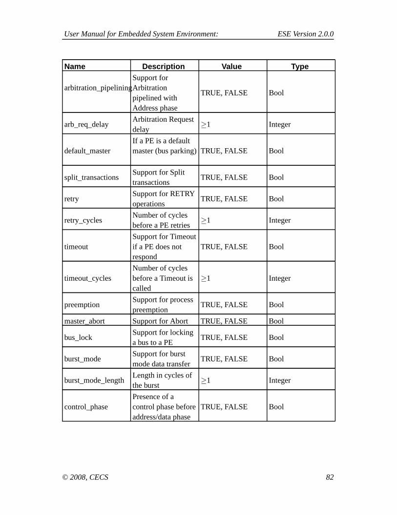
User Manual for Embedded System Environment: ESE Version 2.0.0
Name Description Value Type
arbitration_pipeliningSupport forArbitrationpipelined withAddress phase
TRUE, FALSE Bool
arb_req_delayArbitration Requestdelay
≥1 Integer
default_masterIf a PE is a defaultmaster (bus parking) TRUE, FALSE Bool
split_transactionsSupport for Splittransactions
TRUE, FALSE Bool
retrySupport for RETRYoperations
TRUE, FALSE Bool
retry_cyclesNumber of cyclesbefore a PE retries
≥1 Integer
timeoutSupport for Timeoutif a PE does notrespond
TRUE, FALSE Bool
timeout_cyclesNumber of cyclesbefore a Timeout iscalled
≥1 Integer
preemptionSupport for processpreemption
TRUE, FALSE Bool
master_abort Support for Abort TRUE, FALSE Bool
bus_lockSupport for lockinga bus to a PE
TRUE, FALSE Bool
burst_modeSupport for burstmode data transfer
TRUE, FALSE Bool
burst_mode_lengthLength in cycles ofthe burst
≥1 Integer
control_phasePresence of acontrol phase beforeaddress/data phase
TRUE, FALSE Bool
© 2008, CECS 82

User Manual for Embedded System Environment: ESE Version 2.0.0
Name Description Value Type
control_phase_lengthLength of thecontrol phase incycles
≥1 Integer
address_data_pipeliningSupport forpipelining betweenaddress and dataphases
TRUE, FALSE Bool
© 2008, CECS 83

User Manual for Embedded System Environment: ESE Version 2.0.0
Appendix A. XML stylesheet for PE Data Model
This appendix contains a full XML stylesheet for PE Data Model.
A.1. Data Type
<xs:simpleType name="IdentName"><xs:restriction base="xs:string"><xs:pattern value="_*[a-zA-Z][a-zA-Z0-9_]*"/>
</xs:restriction>
</xs:simpleType>
<xs:simpleType name="IdentNameList"><xs:list itemType="IdentName"/>
</xs:simpleType>
A.2. Elements
<xs:complexType name="ProcUnitModel"><xs:attribute name="version" type="xs:string" use="required"/>
<xs:element name="procunit" type="ProcUnit" minOccurs="1" maxOccurs="unbounded"><xs:complexType><xs:attribute name="type" type="xs:string"/>
<xs:element name="execmodel" type="ExecModel" minOccurs="1" maxOccurs="unbounded"/><xs:element name="memmodel" type="MemModel" minOccurs="1" maxOccurs="unbounded"/><xs:element name="dpmodel" type="DPModel" minOccurs="1" maxOccurs="unbounded"/></xs:complexType>
</xs:element>
</xs:complexType>
<xs:complexType name="ExecModel">
© 2008, CECS 84

User Manual for Embedded System Environment: ESE Version 2.0.0
<xs:attribute name="sched" type="IdentName" use="required"/>
<xs:element name="operation" type="Operation" minOccurs="1" maxOccurs="unbounded"><xs:complexType><xs:attribute name="name" type="IdentName" use="required"/><xs:attribute name="var_type" type="IdentName" use="required"/>
<xs:element name="stgref" type="StgRef" minOccurs="1" maxOccurs="unbounded"><xs:complexType><xs:attribute name="name" type="IdentName" use="required"/><xs:attribute name="flags" use="required"><xs:simpleType><xs:restriction base="xs:string"><xs:enumeration value="COMMIT"/><xs:enumeration value="DEMAND"/><xs:enumeration value="DEMAND COMMIT"/></xs:restriction>
</xs:simpleType></xs:attribute>
<xs:element name="furef" type="FURef" minOccurs="1" maxOccurs="unbounded"/></xs:complexType></xs:element>
</xs:complexType></xs:element>
</xs:complexType>
<xs:complexType name="FURef"><xs:attribute name="type" type="IdentName" use="required"/><xs:attribute name="quantity" type="IdentName" use="required"/><xs:attribute name="mode" type="IdentName" use="required"/>
</xs:complexType>
<xs:complexType name="MemModel"><xs:element name="cache" type="Cache" minOccurs="0" maxOccurs="unbounded">
<xs:complexType><xs:attribute name="policy" type="IdentName" use="required"/>
© 2008, CECS 85

User Manual for Embedded System Environment: ESE Version 2.0.0
<!-- below is for cache which has distinction btn i cache and d cache --><xs:attribute name="i_cache_delay" type="xs:int"/><xs:attribute name="d_cache_delay" type="xs:int"/>
<!-- below is for cache which has no distinction btn i cache and d cache --><xs:attribute name="delay" type="xs:string"/><xs:attribute name="cache_size" type="xs:string"/><xs:attribute name="i_cache_ratio" type="xs:float"/><xs:attribute name="d_cache_ratio" type="xs:float"/>
<xs:element name="InstCache" type="InstCache" minOccurs="0" maxOccurs="unbounded"><xs:attribute name="i_cache_size" type="xs:string" use="required"/><xs:attribute name="i_cache_ratio" type="xs:float" use="required"/></xs:element>
<xs:element name="DataCache" type="DataCache" minOccurs="0" maxOccurs="unbounded"><xs:attribute name="d_cache_size" type="xs:string" use="required"/><xs:attribute name="d_cache_ratio" type="xs:float" use="required"/></xs:element>
</xs:complexType></xs:element><xs:element name="memory" type="Memory" minOccurs="1" maxOccurs="unbounded">
<xs:complexType><xs:attribute name="w_delay" type="xs:int" use="required"/><xs:attribute name="r_delay" type="xs:int" use="required"/>
</xs:complexType></xs:element>
</xs:complexType>
<xs:complexType name="DPModel"><xs:element name="pipeline" type="Pipeline" minOccurs="1" maxOccurs="unbounded">
<xs:complexType><xs:attribute name="name" type="IdentName" use="required"/><xs:attribute name="br_pred_policy" type="IdentName" use="required"><xs:simpleType><xs:restriction base="xs:string"><xs:enumeration value="TAKEN"/><xs:enumeration value="NOT_TAKEN"/></xs:restriction>
© 2008, CECS 86
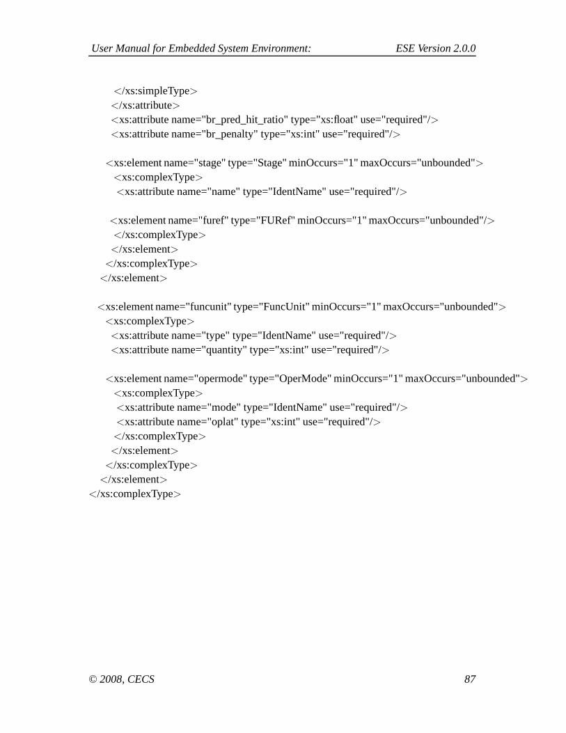
User Manual for Embedded System Environment: ESE Version 2.0.0
</xs:simpleType></xs:attribute><xs:attribute name="br_pred_hit_ratio" type="xs:float" use="required"/><xs:attribute name="br_penalty" type="xs:int" use="required"/>
<xs:element name="stage" type="Stage" minOccurs="1" maxOccurs="unbounded"><xs:complexType><xs:attribute name="name" type="IdentName" use="required"/>
<xs:element name="furef" type="FURef" minOccurs="1" maxOccurs="unbounded"/></xs:complexType></xs:element>
</xs:complexType></xs:element>
<xs:element name="funcunit" type="FuncUnit" minOccurs="1" maxOccurs="unbounded"><xs:complexType><xs:attribute name="type" type="IdentName" use="required"/><xs:attribute name="quantity" type="xs:int" use="required"/>
<xs:element name="opermode" type="OperMode" minOccurs="1" maxOccurs="unbounded"><xs:complexType><xs:attribute name="mode" type="IdentName" use="required"/><xs:attribute name="oplat" type="xs:int" use="required"/></xs:complexType></xs:element>
</xs:complexType></xs:element>
</xs:complexType>
© 2008, CECS 87

User Manual for Embedded System Environment: ESE Version 2.0.0
Appendix B. XML stylesheet for Bus Models
<xs:complexType name="BUS"><xs:attribute name="type" type="IdentName"/><xs:attribute name="address_bus_width" type="xs:int"/><xs:attribute name="data_bus_width" type="xs:int"/><xs:attribute name="max_number_masters" type="xs:int"/><xs:attribute name="fcfs" type="xs:bool"/><xs:attribute name="round_robin" type="xs:bool"/><xs:attribute name="priority" type="xs:bool"/><xs:attribute name="least_freq_used" type="xs:bool"/><xs:attribute name="arbitration_pipelining" type="xs:bool"/><xs:attribute name="arb_req_delay" type="xs:int"/><xs:attribute name="default_master" type="xs:bool"/><xs:attribute name="split_transactions" type="xs:bool"/><xs:attribute name="retry" type="xs:bool"/><xs:attribute name="retry_cycles" type="xs:int"/><xs:attribute name="timeout" type="xs:bool"/><xs:attribute name="timeout_cycles" type="xs:int"/><xs:attribute name="preemption" type="xs:bool"/><xs:attribute name="master_abort" type="xs:bool"/><xs:attribute name="bus_lock" type="xs:bool"/><xs:attribute name="burst_mode" type="xs:bool"/><xs:attribute name="burst_mode_length" type="xs:int"/><xs:attribute name="control_phase" type="xs:bool"/><xs:attribute name="control_phase_length" type="xs:int"/><xs:attribute name="address_data_pipelining" type="xs:bool"/>
</xs:complexType>
© 2008, CECS 88

User Manual for Embedded System Environment: ESE Version 2.0.0
Appendix C. Example XMLs
This appendix contains a full XML stylesheet for PE Data Model.
C.1. Example XML for MicroBlaze
<ProcUnitModel version = "0.0.1"><ProcUnit type="MICROBLAZE">
<ExecModel sched="PIPELINE"><Operation name="ret">
<StgRef name = "IF"><FURef type = "InstFetch" mode = "DEFAULT"/>
</StgRef><StgRef name = "ID" flags ="DEMAND">
<FURef type = "InstDecode" mode = "DEFAULT"/></StgRef><StgRef name = "EX" flags ="COMMIT">
<FURef type="reg" mode="RdReg"/></StgRef>
</Operation>
<Operation name="malloc"> <!-- allocate memory from system heap --><StgRef name = "IF">
<FURef type = "InstFetch" mode = "DEFAULT"/></StgRef><StgRef name = "ID" flags ="DEMAND">
<FURef type = "InstDecode" mode = "DEFAULT"/></StgRef><StgRef name = "EX" flags ="COMMIT">
<FURef type="reg" mode="WrReg"/></StgRef>
</Operation>
<Operation name="free"> <!-- returns memory back to system heap --><StgRef name = "IF">
<FURef type = "InstFetch" mode = "DEFAULT"/></StgRef><StgRef name = "ID" flags ="DEMAND">
<FURef type = "InstDecode" mode = "DEFAULT"/>
© 2008, CECS 89

User Manual for Embedded System Environment: ESE Version 2.0.0
</StgRef><StgRef name = "EX" flags ="COMMIT">
<FURef type="reg" mode="WrReg"/></StgRef>
</Operation>
<Operation name="alloca"> <!-- allocate memory from current stack frame --><StgRef name = "IF">
<FURef type = "InstFetch" mode = "DEFAULT"/></StgRef><StgRef name = "ID" flags ="DEMAND">
<FURef type = "InstDecode" mode = "DEFAULT"/></StgRef><StgRef name = "EX" flags ="COMMIT">
<FURef type="reg" mode="WrReg"/></StgRef>
</Operation>
<Operation name="load"> <!-- read from memory --><StgRef name = "IF">
<FURef type = "InstFetch" mode = "DEFAULT"/></StgRef><StgRef name = "ID" flags ="DEMAND">
<FURef type = "InstDecode" mode = "DEFAULT"/></StgRef><StgRef name = "EX" flags ="COMMIT">
<FURef type="mem-Port" mode="RdPort"/></StgRef>
</Operation>
<Operation name="store"> <!-- write to memory --><StgRef name = "IF">
<FURef type = "InstFetch" mode = "DEFAULT"/></StgRef><StgRef name = "ID" flags ="DEMAND">
<FURef type = "InstDecode" mode = "DEFAULT"/></StgRef><StgRef name = "EX" flags ="COMMIT">
<FURef type="mem-Port" mode="WrPort"/></StgRef>
</Operation>
© 2008, CECS 90

User Manual for Embedded System Environment: ESE Version 2.0.0
<Operation name="call"> <!-- function call --><StgRef name = "IF">
<FURef type = "InstFetch" mode = "DEFAULT"/></StgRef><StgRef name = "ID" flags ="DEMAND">
<FURef type = "InstDecode" mode = "DEFAULT"/></StgRef><StgRef name = "EX" flags ="COMMIT">
<FURef type="reg" mode="RdReg"/></StgRef>
</Operation>
<Operation name="br"><StgRef name = "IF">
<FURef type = "InstFetch" mode = "DEFAULT"/></StgRef><StgRef name = "ID" flags ="DEMAND">
<FURef type = "InstDecode" mode = "DEFAULT"/></StgRef><StgRef name = "EX" flags ="COMMIT">
<FURef type="int-ALU" mode="IntALU"/></StgRef>
</Operation>
<Operation name="add" var_type="int"><StgRef name = "IF">
<FURef type = "InstFetch" mode = "DEFAULT"/></StgRef><StgRef name = "ID" flags ="DEMAND">
<FURef type = "InstDecode" mode = "DEFAULT"/></StgRef><StgRef name = "EX" flags ="COMMIT">
<FURef type="int-ALU" mode="IntALU"/></StgRef>
</Operation>
<Operation name="add" var_type="float"><StgRef name = "IF">
<FURef type = "InstFetch" mode = "DEFAULT"/></StgRef>
© 2008, CECS 91

User Manual for Embedded System Environment: ESE Version 2.0.0
<StgRef name = "ID" flags ="DEMAND"><FURef type = "InstDecode" mode = "DEFAULT"/>
</StgRef><StgRef name = "EX" flags ="COMMIT">
<FURef type="FP-ALU" mode="FPAdd"/></StgRef>
</Operation>
<Operation name="sub" var_type="int"><StgRef name = "IF">
<FURef type = "InstFetch" mode = "DEFAULT"/></StgRef><StgRef name = "ID" flags ="DEMAND">
<FURef type = "InstDecode" mode = "DEFAULT"/></StgRef><StgRef name = "EX" flags ="COMMIT">
<FURef type="int-ALU" mode="IntALU"/></StgRef>
</Operation>
<Operation name="sub" var_type="float"><StgRef name = "IF">
<FURef type = "InstFetch" mode = "DEFAULT"/></StgRef><StgRef name = "ID" flags ="DEMAND">
<FURef type = "InstDecode" mode = "DEFAULT"/></StgRef><StgRef name = "EX" flags ="COMMIT">
<FURef type="FP-ALU" mode="FPAdd"/></StgRef>
</Operation>
<Operation name="mul" var_type="int"><StgRef name = "IF">
<FURef type = "InstFetch" mode = "DEFAULT"/></StgRef><StgRef name = "ID" flags ="DEMAND">
<FURef type = "InstDecode" mode = "DEFAULT"/></StgRef><StgRef name = "EX" flags ="COMMIT">
<FURef type="int-Mult/Div" mode="IntMult"/>
© 2008, CECS 92
User Manual for Embedded System Environment: ESE Version 2.0.0
</StgRef></Operation>
<Operation name="mul" var_type="float"><StgRef name = "IF">
<FURef type = "InstFetch" mode = "DEFAULT"/></StgRef><StgRef name = "ID" flags ="DEMAND">
<FURef type = "InstDecode" mode = "DEFAULT"/></StgRef><StgRef name = "EX" flags ="COMMIT">
<FURef type="FP-Mult/Div" mode="FPMult"/></StgRef>
</Operation>
<Operation name="udiv"><StgRef name = "IF">
<FURef type = "InstFetch" mode = "DEFAULT"/></StgRef><StgRef name = "ID" flags ="DEMAND">
<FURef type = "InstDecode" mode = "DEFAULT"/></StgRef><StgRef name = "EX" flags ="COMMIT">
<FURef type="int-Mult/Div" mode="IntDiv"/></StgRef>
</Operation>
<Operation name="sdiv"><StgRef name = "IF">
<FURef type = "InstFetch" mode = "DEFAULT"/></StgRef><StgRef name = "ID" flags ="DEMAND">
<FURef type = "InstDecode" mode = "DEFAULT"/></StgRef><StgRef name = "EX" flags ="COMMIT">
<FURef type="int-Mult/Div" mode="IntDiv"/></StgRef>
</Operation>
<Operation name="fdiv"><StgRef name = "IF">
<FURef type = "InstFetch" mode = "DEFAULT"/>
© 2008, CECS 93

User Manual for Embedded System Environment: ESE Version 2.0.0
</StgRef><StgRef name = "ID" flags ="DEMAND">
<FURef type = "InstDecode" mode = "DEFAULT"/></StgRef><StgRef name = "EX" flags ="COMMIT">
<FURef type="FP-Mult/Div" mode="FPDiv"/></StgRef>
</Operation>
<Operation name="urem"> <!-- returns remainder of a division --><StgRef name = "IF">
<FURef type = "InstFetch" mode = "DEFAULT"/></StgRef><StgRef name = "ID" flags ="DEMAND">
<FURef type = "InstDecode" mode = "DEFAULT"/></StgRef><StgRef name = "EX" flags ="COMMIT">
<FURef type="int-Mult/Div" mode="IntDiv"/></StgRef>
</Operation>
<Operation name="srem"><StgRef name = "IF">
<FURef type = "InstFetch" mode = "DEFAULT"/></StgRef><StgRef name = "ID" flags ="DEMAND">
<FURef type = "InstDecode" mode = "DEFAULT"/></StgRef><StgRef name = "EX" flags ="COMMIT">
<FURef type="int-Mult/Div" mode="IntDiv"/></StgRef>
</Operation>
<Operation name="frem"><StgRef name = "IF">
<FURef type = "InstFetch" mode = "DEFAULT"/></StgRef><StgRef name = "ID" flags ="DEMAND">
<FURef type = "InstDecode" mode = "DEFAULT"/></StgRef><StgRef name = "EX" flags ="COMMIT">
© 2008, CECS 94

User Manual for Embedded System Environment: ESE Version 2.0.0
<FURef type="FP-Mult/Div" mode="FPDiv"/></StgRef>
</Operation>
<Operation name="shl"> <!-- shift --><StgRef name = "IF">
<FURef type = "InstFetch" mode = "DEFAULT"/></StgRef><StgRef name = "ID" flags ="DEMAND">
<FURef type = "InstDecode" mode = "DEFAULT"/></StgRef><StgRef name = "EX" flags ="COMMIT">
<FURef type="int-ALU" mode="IntALU"/></StgRef>
</Operation>
<Operation name="shr"> <!-- shift --><StgRef name = "IF">
<FURef type = "InstFetch" mode = "DEFAULT"/></StgRef><StgRef name = "ID" flags ="DEMAND">
<FURef type = "InstDecode" mode = "DEFAULT"/></StgRef><StgRef name = "EX" flags ="COMMIT">
<FURef type="int-ALU" mode="IntALU"/></StgRef>
</Operation>
<Operation name="lshr"> <!-- logical shift --><StgRef name = "IF">
<FURef type = "InstFetch" mode = "DEFAULT"/></StgRef><StgRef name = "ID" flags ="DEMAND">
<FURef type = "InstDecode" mode = "DEFAULT"/></StgRef><StgRef name = "EX" flags ="COMMIT">
<FURef type="int-ALU" mode="IntALU"/></StgRef>
</Operation>
<Operation name="ashr"> <!-- arithmetic shift --><StgRef name = "IF">
© 2008, CECS 95
User Manual for Embedded System Environment: ESE Version 2.0.0
<FURef type = "InstFetch" mode = "DEFAULT"/></StgRef><StgRef name = "ID" flags ="DEMAND">
<FURef type = "InstDecode" mode = "DEFAULT"/></StgRef><StgRef name = "EX" flags ="COMMIT">
<FURef type="int-ALU" mode="IntALU"/></StgRef>
</Operation>
<Operation name="and"><StgRef name = "IF">
<FURef type = "InstFetch" mode = "DEFAULT"/></StgRef><StgRef name = "ID" flags ="DEMAND">
<FURef type = "InstDecode" mode = "DEFAULT"/></StgRef><StgRef name = "EX" flags ="COMMIT">
<FURef type="int-ALU" mode="IntALU"/></StgRef>
</Operation>
<Operation name="or"><StgRef name = "IF">
<FURef type = "InstFetch" mode = "DEFAULT"/></StgRef><StgRef name = "ID" flags ="DEMAND">
<FURef type = "InstDecode" mode = "DEFAULT"/></StgRef><StgRef name = "EX" flags ="COMMIT">
<FURef type="int-ALU" mode="IntALU"/></StgRef>
</Operation>
<Operation name="xor"><StgRef name = "IF">
<FURef type = "InstFetch" mode = "DEFAULT"/></StgRef><StgRef name = "ID" flags ="DEMAND">
<FURef type = "InstDecode" mode = "DEFAULT"/></StgRef>
© 2008, CECS 96

User Manual for Embedded System Environment: ESE Version 2.0.0
<StgRef name = "EX" flags ="COMMIT"><FURef type="int-ALU" mode="IntALU"/>
</StgRef></Operation>
<Operation name="fptoui"><StgRef name = "IF">
<FURef type = "InstFetch" mode = "DEFAULT"/></StgRef><StgRef name = "ID" flags ="DEMAND">
<FURef type = "InstDecode" mode = "DEFAULT"/></StgRef><StgRef name = "EX" flags ="COMMIT">
<FURef type="FP-ALU" mode="FPCvt"/></StgRef>
</Operation>
<Operation name="fptosi"><StgRef name = "IF">
<FURef type = "InstFetch" mode = "DEFAULT"/></StgRef><StgRef name = "ID" flags ="DEMAND">
<FURef type = "InstDecode" mode = "DEFAULT"/></StgRef><StgRef name = "EX" flags ="COMMIT">
<FURef type="FP-ALU" mode="FPCvt"/></StgRef>
</Operation>
<Operation name="uitofp"><StgRef name = "IF">
<FURef type = "InstFetch" mode = "DEFAULT"/></StgRef><StgRef name = "ID" flags ="DEMAND">
<FURef type = "InstDecode" mode = "DEFAULT"/></StgRef><StgRef name = "EX" flags ="COMMIT">
<FURef type="FP-ALU" mode="FPCvt"/></StgRef>
</Operation>
<Operation name="sitofp">
© 2008, CECS 97

User Manual for Embedded System Environment: ESE Version 2.0.0
<StgRef name = "IF"><FURef type = "InstFetch" mode = "DEFAULT"/>
</StgRef><StgRef name = "ID" flags ="DEMAND">
<FURef type = "InstDecode" mode = "DEFAULT"/></StgRef><StgRef name = "EX" flags ="COMMIT">
<FURef type="FP-ALU" mode="FPCvt"/></StgRef>
</Operation>
<Operation name="icmp"><StgRef name = "IF">
<FURef type = "InstFetch" mode = "DEFAULT"/></StgRef><StgRef name = "ID" flags ="DEMAND">
<FURef type = "InstDecode" mode = "DEFAULT"/></StgRef><StgRef name = "EX" flags ="COMMIT">
<FURef type="int-ALU" mode="IntALU"/></StgRef>
</Operation>
<Operation name="fcmp"><StgRef name = "IF">
<FURef type = "InstFetch" mode = "DEFAULT"/></StgRef><StgRef name = "ID" flags ="DEMAND">
<FURef type = "InstDecode" mode = "DEFAULT"/></StgRef><StgRef name = "EX" flags ="COMMIT">
<FURef type="FP-ALU" mode="FPCmp"/></StgRef>
</Operation>
<Operation name="seteq"><StgRef name = "IF">
<FURef type = "InstFetch" mode = "DEFAULT"/></StgRef><StgRef name = "ID" flags ="DEMAND">
<FURef type = "InstDecode" mode = "DEFAULT"/>
© 2008, CECS 98

User Manual for Embedded System Environment: ESE Version 2.0.0
</StgRef><StgRef name = "EX" flags ="COMMIT">
<FURef type="int-ALU" mode="IntALU"/></StgRef>
</Operation>
<Operation name="setne"><StgRef name = "IF">
<FURef type = "InstFetch" mode = "DEFAULT"/></StgRef><StgRef name = "ID" flags ="DEMAND">
<FURef type = "InstDecode" mode = "DEFAULT"/></StgRef><StgRef name = "EX" flags ="COMMIT">
<FURef type="int-ALU" mode="IntALU"/></StgRef>
</Operation>
<Operation name="setle"><StgRef name = "IF">
<FURef type = "InstFetch" mode = "DEFAULT"/></StgRef><StgRef name = "ID" flags ="DEMAND">
<FURef type = "InstDecode" mode = "DEFAULT"/></StgRef><StgRef name = "EX" flags ="COMMIT">
<FURef type="int-ALU" mode="IntALU"/></StgRef>
</Operation>
<Operation name="setge"><StgRef name = "IF">
<FURef type = "InstFetch" mode = "DEFAULT"/></StgRef><StgRef name = "ID" flags ="DEMAND">
<FURef type = "InstDecode" mode = "DEFAULT"/></StgRef><StgRef name = "EX" flags ="COMMIT">
<FURef type="int-ALU" mode="IntALU"/></StgRef>
</Operation>
© 2008, CECS 99

User Manual for Embedded System Environment: ESE Version 2.0.0
<Operation name="setlt"><StgRef name = "IF">
<FURef type = "InstFetch" mode = "DEFAULT"/></StgRef><StgRef name = "ID" flags ="DEMAND">
<FURef type = "InstDecode" mode = "DEFAULT"/></StgRef><StgRef name = "EX" flags ="COMMIT">
<FURef type="int-ALU" mode="IntALU"/></StgRef>
</Operation>
<Operation name="setgt"><StgRef name = "IF">
<FURef type = "InstFetch" mode = "DEFAULT"/></StgRef><StgRef name = "ID" flags ="DEMAND">
<FURef type = "InstDecode" mode = "DEFAULT"/></StgRef><StgRef name = "EX" flags ="COMMIT">
<FURef type="int-ALU" mode="IntALU"/></StgRef>
</Operation>
<Operation name="cast" var_type="int"><StgRef name = "IF">
<FURef type = "InstFetch" mode = "DEFAULT"/></StgRef><StgRef name = "ID" flags ="DEMAND">
<FURef type = "InstDecode" mode = "DEFAULT"/></StgRef><StgRef name = "EX" flags ="COMMIT">
<FURef type="int-ALU" mode="IntALU"/></StgRef>
</Operation>
<Operation name="cast" var_type="float"><StgRef name = "IF">
<FURef type = "InstFetch" mode = "DEFAULT"/></StgRef><StgRef name = "ID" flags ="DEMAND">
© 2008, CECS 100
User Manual for Embedded System Environment: ESE Version 2.0.0
<FURef type = "InstDecode" mode = "DEFAULT"/></StgRef><StgRef name = "EX" flags ="COMMIT">
<FURef type="FP-ALU" mode="FPCvt"/></StgRef>
</Operation>
<Operation name="cast" var_type="double"><StgRef name = "IF">
<FURef type = "InstFetch" mode = "DEFAULT"/></StgRef><StgRef name = "ID" flags ="DEMAND">
<FURef type = "InstDecode" mode = "DEFAULT"/></StgRef><StgRef name = "EX" flags ="COMMIT">
<FURef type="FP-ALU" mode="FPCvt"/></StgRef>
</Operation>
<Operation name="getelementptr"><StgRef name = "IF">
<FURef type = "InstFetch" mode = "DEFAULT"/></StgRef><StgRef name = "ID" flags ="DEMAND">
<FURef type = "InstDecode" mode = "DEFAULT"/></StgRef><StgRef name = "EX" flags ="COMMIT">
<FURef type="int-ALU" mode="IntALU"/></StgRef>
</Operation>
<Operation name="phi"><StgRef name = "IF">
<FURef type = "InstFetch" mode = "DEFAULT"/></StgRef><StgRef name = "ID" flags ="DEMAND">
<FURef type = "InstDecode" mode = "DEFAULT"/></StgRef><StgRef name = "EX" flags ="COMMIT">
<FURef type="int-ALU" mode="IntALU"/>
© 2008, CECS 101
User Manual for Embedded System Environment: ESE Version 2.0.0
</StgRef></Operation>
<Operation name="unreachable"><StgRef name = "IF">
<FURef type = "InstFetch" mode = "DEFAULT"/></StgRef><StgRef name = "ID" flags ="DEMAND">
<FURef type = "InstDecode" mode = "DEFAULT"/></StgRef><StgRef name = "EX" flags ="COMMIT">
<FURef type="int-ALU" mode="IntALU"/></StgRef>
</Operation>
<Operation name="invoke"><StgRef name = "IF">
<FURef type = "InstFetch" mode = "DEFAULT"/></StgRef><StgRef name = "ID" flags ="DEMAND">
<FURef type = "InstDecode" mode = "DEFAULT"/></StgRef><StgRef name = "EX" flags ="COMMIT">
<FURef type="int-ALU" mode="IntALU"/></StgRef>
</Operation>
<Operation name="unwind"><StgRef name = "IF">
<FURef type = "InstFetch" mode = "DEFAULT"/></StgRef><StgRef name = "ID" flags ="DEMAND">
<FURef type = "InstDecode" mode = "DEFAULT"/></StgRef><StgRef name = "EX" flags ="COMMIT">
<FURef type="int-ALU" mode="IntALU"/></StgRef>
</Operation>
<Operation name="switch"><StgRef name = "IF">
<FURef type = "InstFetch" mode = "DEFAULT"/>
© 2008, CECS 102

User Manual for Embedded System Environment: ESE Version 2.0.0
</StgRef><StgRef name = "ID" flags ="DEMAND">
<FURef type = "InstDecode" mode = "DEFAULT"/></StgRef><StgRef name = "EX" flags ="COMMIT">
<FURef type="int-ALU" mode="IntALU"/></StgRef>
</Operation>
<Operation name="select"><StgRef name = "IF">
<FURef type = "InstFetch" mode = "DEFAULT"/></StgRef><StgRef name = "ID" flags ="DEMAND">
<FURef type = "InstDecode" mode = "DEFAULT"/></StgRef><StgRef name = "EX" flags ="COMMIT">
<FURef type="int-ALU" mode="IntALU"/></StgRef>
</Operation>
</ExecModel>
<MemModel><Cache policy = "D-Mapped" i_cache_delay = "1" d_cache_delay = "1">
<InstCache i_cache_size = "1K" i_cache_ratio = "0.6614"/><InstCache i_cache_size = "2K" i_cache_ratio = "0.7917"/><InstCache i_cache_size = "4K" i_cache_ratio = "0.8606"/><InstCache i_cache_size = "8K" i_cache_ratio = "0.9503"/><InstCache i_cache_size = "16K" i_cache_ratio = "0.9779"/><InstCache i_cache_size = "32K" i_cache_ratio = "0.9805"/><InstCache i_cache_size = "64K" i_cache_ratio = "0.9817"/><DataCache d_cache_size = "2K" d_cache_ratio = "0.6379"/><DataCache d_cache_size = "4K" d_cache_ratio = "0.6661"/><DataCache d_cache_size = "8K" d_cache_ratio = "0.6714"/><DataCache d_cache_size = "16K" d_cache_ratio = "0.6996"/><DataCache d_cache_size = "32K" d_cache_ratio = "0.6996"/><DataCache d_cache_size = "64K" d_cache_ratio = "0.6996"/>
</Cache><Memory r_delay = "8" w_delay = "3"/>
© 2008, CECS 103

User Manual for Embedded System Environment: ESE Version 2.0.0
</MemModel>
<DPModel><Pipeline name = "default" br_pred_policy = "TAKEN" br_pred_hit_ratio = "60.00" br_penalty = "2">
<Stage name = "IF"><FURef type = "InstFetch" quantity = "1"/>
</Stage><Stage name = "ID">
<FURef type = "InstDecode" quantity = "1"/></Stage><Stage name = "EX">
<FURef type = "reg" quantity = "32"/><FURef type = "mem-Port" quantity = "1"/><FURef type = "int-ALU" quantity = "1"/><FURef type = "int-Mult/Div" quantity = "1"/><FURef type = "FP-ALU" quantity = "1"/><FURef type = "FP-Mult/Div" quantity = "1"/>
</Stage></Pipeline><FuncUnit type="InstFetch" quantity="1">
<OperMode mode="DEFAULT" oplat="1"/></FuncUnit><FuncUnit type="InstDecode" quantity="1">
<OperMode mode="DEFAULT" oplat="1"/></FuncUnit><FuncUnit type="reg" quantity="32">
<OperMode mode="RdReg" oplat="1"/><OperMode mode="WrReg" oplat="1"/>
</FuncUnit><FuncUnit type="mem-Port" quantity="1">
<OperMode mode="RdPort" oplat="2"/><OperMode mode="WrPort" oplat="1"/>
</FuncUnit><FuncUnit type="int-ALU" quantity="1">
<OperMode mode="IntALU" oplat="1"/></FuncUnit><FuncUnit type="int-Mult/Div" quantity="1">
<OperMode mode="IntMult" oplat="3"/>
© 2008, CECS 104

User Manual for Embedded System Environment: ESE Version 2.0.0
<OperMode mode="IntDiv" oplat="34"/></FuncUnit><FuncUnit type="FP-ALU" quantity="1">
<OperMode mode="FPAdd" oplat="6"/><OperMode mode="FPCmp" oplat="3"/><OperMode mode="FPCvt" oplat="3"/>
</FuncUnit><FuncUnit type="FP-Mult/Div" quantity="1">
<OperMode mode="FPMult" oplat="6"/><OperMode mode="FPDiv" oplat="30"/><OperMode mode="FPSqrt" oplat="6"/>
</FuncUnit>
</DPModel></ProcUnit>
</ProcUnitModel>
C.2. Example XML for Custom Hardware
<ProcUnitModel version = "0.0.1"><ProcUnit type="DCT32">
<ExecModel sched="LIST_SCHED"><Operation name="ret">
<StgRef name = "SINGLE" flags = "COMMIT DEMAND"><FURef type="reg" mode="RdReg"/>
</StgRef></Operation>
<Operation name="malloc"> <!-- allocate memory from system heap --><StgRef name = "SINGLE" flags = "COMMIT DEMAND">
<FURef type="reg" mode="WrReg"/></StgRef>
</Operation>
<Operation name="free"> <!-- returns memory back to system heap --><StgRef name = "SINGLE" flags = "COMMIT DEMAND">
<FURef type="reg" mode="WrReg"/>
© 2008, CECS 105

User Manual for Embedded System Environment: ESE Version 2.0.0
</StgRef></Operation>
<Operation name="alloca"> <!-- allocate memory from current stack frame --><StgRef name = "SINGLE" flags = "COMMIT DEMAND">
<FURef type="reg" mode="WrReg"/></StgRef>
</Operation>
<Operation name="load"> <!-- read from memory --><StgRef name = "SINGLE" flags = "COMMIT DEMAND">
<FURef type="mem-Port" mode="RdPort"/></StgRef>
</Operation>
<Operation name="store"> <!-- write to memory --><StgRef name = "SINGLE" flags = "COMMIT DEMAND">
<FURef type="mem-Port" mode="WrPort"/></StgRef>
</Operation>
<Operation name="call"> <!-- function call --><StgRef name = "SINGLE" flags = "COMMIT DEMAND">
<FURef type="reg" mode="RdReg"/></StgRef>
</Operation>
<Operation name="br"><StgRef name = "SINGLE" flags = "COMMIT DEMAND">
<FURef type="int-ALU" mode="IntALU"/></StgRef>
</Operation>
<Operation name="add" var_type="int"><StgRef name = "SINGLE" flags = "COMMIT DEMAND">
<FURef type="int-ALU" mode="IntALU"/></StgRef>
</Operation>
<Operation name="add" var_type="float"><StgRef name = "SINGLE" flags = "COMMIT DEMAND">
<FURef type="FP-ALU" mode="FPAdd"/></StgRef>
</Operation>
© 2008, CECS 106
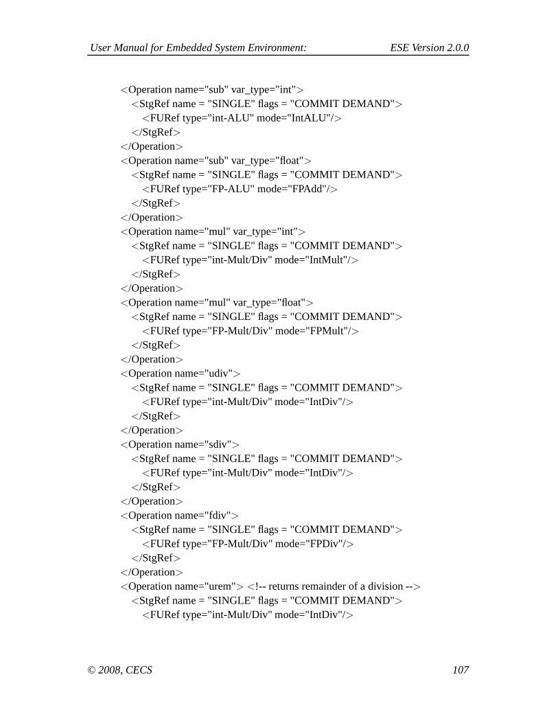
User Manual for Embedded System Environment: ESE Version 2.0.0
<Operation name="sub" var_type="int"><StgRef name = "SINGLE" flags = "COMMIT DEMAND">
<FURef type="int-ALU" mode="IntALU"/></StgRef>
</Operation>
<Operation name="sub" var_type="float"><StgRef name = "SINGLE" flags = "COMMIT DEMAND">
<FURef type="FP-ALU" mode="FPAdd"/></StgRef>
</Operation>
<Operation name="mul" var_type="int"><StgRef name = "SINGLE" flags = "COMMIT DEMAND">
<FURef type="int-Mult/Div" mode="IntMult"/></StgRef>
</Operation>
<Operation name="mul" var_type="float"><StgRef name = "SINGLE" flags = "COMMIT DEMAND">
<FURef type="FP-Mult/Div" mode="FPMult"/></StgRef>
</Operation>
<Operation name="udiv"><StgRef name = "SINGLE" flags = "COMMIT DEMAND">
<FURef type="int-Mult/Div" mode="IntDiv"/></StgRef>
</Operation>
<Operation name="sdiv"><StgRef name = "SINGLE" flags = "COMMIT DEMAND">
<FURef type="int-Mult/Div" mode="IntDiv"/></StgRef>
</Operation>
<Operation name="fdiv"><StgRef name = "SINGLE" flags = "COMMIT DEMAND">
<FURef type="FP-Mult/Div" mode="FPDiv"/></StgRef>
</Operation>
<Operation name="urem"> <!-- returns remainder of a division --><StgRef name = "SINGLE" flags = "COMMIT DEMAND">
<FURef type="int-Mult/Div" mode="IntDiv"/>
© 2008, CECS 107

User Manual for Embedded System Environment: ESE Version 2.0.0
</StgRef></Operation>
<Operation name="srem"><StgRef name = "SINGLE" flags = "COMMIT DEMAND">
<FURef type="int-Mult/Div" mode="IntDiv"/></StgRef>
</Operation>
<Operation name="frem"><StgRef name = "SINGLE" flags = "COMMIT DEMAND">
<FURef type="FP-Mult/Div" mode="FPDiv"/></StgRef>
</Operation>
<Operation name="shl"> <!-- shift --><StgRef name = "SINGLE" flags = "COMMIT DEMAND">
<FURef type="int-ALU" mode="IntALU"/></StgRef>
</Operation>
<Operation name="shr"> <!-- shift --><StgRef name = "SINGLE" flags = "COMMIT DEMAND">
<FURef type="int-ALU" mode="IntALU"/></StgRef>
</Operation>
<Operation name="lshr"> <!-- logical shift --><StgRef name = "SINGLE" flags = "COMMIT DEMAND">
<FURef type="logic-SHIFT" mode="shift"/></StgRef>
</Operation>
<Operation name="ashr"> <!-- arithmetic shift --><StgRef name = "SINGLE" flags = "COMMIT DEMAND">
<FURef type="int-ALU" mode="IntALU"/></StgRef>
</Operation>
<Operation name="and"><StgRef name = "SINGLE" flags = "COMMIT DEMAND">
<FURef type="int-ALU" mode="IntALU"/></StgRef>
</Operation>
<Operation name="or">
© 2008, CECS 108

User Manual for Embedded System Environment: ESE Version 2.0.0
<StgRef name = "SINGLE" flags = "COMMIT DEMAND"><FURef type="int-ALU" mode="IntALU"/>
</StgRef></Operation>
<Operation name="xor"><StgRef name = "SINGLE" flags = "COMMIT DEMAND">
<FURef type="int-ALU" mode="IntALU"/></StgRef>
</Operation>
<Operation name="fptoui"><StgRef name = "SINGLE" flags = "COMMIT DEMAND">
<FURef type="FP-ALU" mode="FPCvt"/></StgRef>
</Operation>
<Operation name="fptosi"><StgRef name = "SINGLE" flags = "COMMIT DEMAND">
<FURef type="FP-ALU" mode="FPCvt"/></StgRef>
</Operation>
<Operation name="uitofp"><StgRef name = "SINGLE" flags = "COMMIT DEMAND">
<FURef type="FP-ALU" mode="FPCvt"/></StgRef>
</Operation>
<Operation name="sitofp"><StgRef name = "SINGLE" flags = "COMMIT DEMAND">
<FURef type="FP-ALU" mode="FPCvt"/></StgRef>
</Operation>
<Operation name="icmp"><StgRef name = "SINGLE" flags = "COMMIT DEMAND">
<FURef type="int-ALU" mode="IntALU"/></StgRef>
</Operation>
<Operation name="fcmp"><StgRef name = "SINGLE" flags = "COMMIT DEMAND">
<FURef type="FP-ALU" mode="FPCmp"/></StgRef>
© 2008, CECS 109

User Manual for Embedded System Environment: ESE Version 2.0.0
</Operation>
<Operation name="seteq"><StgRef name = "SINGLE" flags = "COMMIT DEMAND">
<FURef type="int-ALU" mode="IntALU"/></StgRef>
</Operation>
<Operation name="setne"><StgRef name = "SINGLE" flags = "COMMIT DEMAND">
<FURef type="int-ALU" mode="IntALU"/></StgRef>
</Operation>
<Operation name="setle"><StgRef name = "SINGLE" flags = "COMMIT DEMAND">
<FURef type="int-ALU" mode="IntALU"/></StgRef>
</Operation>
<Operation name="setge"><StgRef name = "SINGLE" flags = "COMMIT DEMAND">
<FURef type="int-ALU" mode="IntALU"/></StgRef>
</Operation>
<Operation name="setlt"><StgRef name = "SINGLE" flags = "COMMIT DEMAND">
<FURef type="int-ALU" mode="IntALU"/></StgRef>
</Operation>
<Operation name="setgt"><StgRef name = "SINGLE" flags = "COMMIT DEMAND">
<FURef type="int-ALU" mode="IntALU"/></StgRef>
</Operation>
<Operation name="cast" var_type="int"><StgRef name = "SINGLE" flags = "COMMIT DEMAND">
<FURef type="int-ALU" mode="IntALU"/></StgRef>
</Operation>
<Operation name="cast" var_type="float"><StgRef name = "SINGLE" flags = "COMMIT DEMAND">
© 2008, CECS 110

User Manual for Embedded System Environment: ESE Version 2.0.0
<FURef type="FP-ALU" mode="FPCvt"/></StgRef>
</Operation>
<Operation name="getelementptr"><StgRef name = "SINGLE" flags = "COMMIT DEMAND">
<FURef type="int-ALU" mode="IntALU"/></StgRef>
</Operation>
<Operation name="phi"><StgRef name = "SINGLE" flags = "COMMIT DEMAND">
<FURef type="int-ALU" mode="IntALU"/></StgRef>
</Operation>
<Operation name="unreachable"><StgRef name = "SINGLE" flags = "COMMIT DEMAND">
<FURef type="int-ALU" mode="IntALU"/></StgRef>
</Operation>
<Operation name="invoke"><StgRef name = "SINGLE" flags = "COMMIT DEMAND">
<FURef type="int-ALU" mode="IntALU"/></StgRef>
</Operation>
<Operation name="unwind"><StgRef name = "SINGLE" flags = "COMMIT DEMAND">
<FURef type="int-ALU" mode="IntALU"/></StgRef>
</Operation>
<Operation name="switch"><StgRef name = "SINGLE" flags = "COMMIT DEMAND">
<FURef type="int-ALU" mode="IntALU"/></StgRef>
</Operation>
<Operation name="select"><StgRef name = "SINGLE" flags = "COMMIT DEMAND">
<FURef type="int-ALU" mode="IntALU"/></StgRef>
© 2008, CECS 111

User Manual for Embedded System Environment: ESE Version 2.0.0
</Operation>
</ExecModel><DPModel><Pipeline name = "default" br_pred_policy = "TAKEN" br_pred_hit_ratio = "100.00" br_penalty = "0">
<Stage name = "SINGLE"><FURef type = "reg" quantity = "32"/><FURef type = "mem-Port" quantity = "1"/><FURef type = "int-ALU" quantity = "1"/><FURef type = "int-Mult/Div" quantity = "1"/><FURef type = "logic-SHIFT" quantity = "3"/><FURef type = "FP-ALU" quantity = "1"/><FURef type = "FP-Mult/Div" quantity = "1"/>
</Stage></Pipeline><FuncUnit type="reg" quantity="32">
<OperMode mode="RdReg" oplat="1"/><OperMode mode="WrReg" oplat="1"/>
</FuncUnit><FuncUnit type="mem-Port" quantity="1">
<OperMode mode="RdPort" oplat="1"/><OperMode mode="WrPort" oplat="1"/>
</FuncUnit><FuncUnit type="int-ALU" quantity="1">
<OperMode mode="IntALU" oplat="1"/></FuncUnit><FuncUnit type="int-Mult/Div" quantity="1">
<OperMode mode="IntMult" oplat="3"/><OperMode mode="IntDiv" oplat="20"/>
</FuncUnit><FuncUnit type="logic-SHIFT" quantity="3">
<OperMode mode="shift" oplat="1"/></FuncUnit><FuncUnit type="FP-ALU" quantity="1">
<OperMode mode="FPAdd" oplat="2"/><OperMode mode="FPCmp" oplat="2"/><OperMode mode="FPCvt" oplat="2"/>
</FuncUnit><FuncUnit type="FP-Mult/Div" quantity="1">
© 2008, CECS 112

User Manual for Embedded System Environment: ESE Version 2.0.0
<OperMode mode="FPMult" oplat="4"/><OperMode mode="FPDiv" oplat="12"/><OperMode mode="FPSqrt" oplat="24"/>
</FuncUnit></DPModel>
</ProcUnit></ProcUnitModel>
C.3. Example XML for OPB
<BUS data_bus_width = "32"arb_req_delay = "1"arbitration_pipelining = "true"address_data_pipelining = "true"address_bus_width = "32"default_master = "true"bus_lock = "true"split_transactions = "false"retry = "true"retry_cycles = "1"timeout = "true"timeout_cycles = "16"preemption = "true"burst_mode = "true"burst_mode_length = "240"fcfs = "true"round_robin = "true"priority = "true"least_freq_used = "true"/>
© 2008, CECS 113