user manual for x10 ocs - hornerautomation.com
TRANSCRIPT

USER MANUAL FOR X10 OCS
MAN1277-02-EN_X10_UserManual
HE-X10A, HE-X10R

MAN1277-02-EN_X10_UserManual
F e b r u a r y 2 4 , 2 0 2 1 P a g e 2 | 189
PREFACE
This manual explains how to use the X10 OCS. Copyright© 2020 Horner APG, LLC, 59 South State Avenue, Indianapolis, Indiana 46201. All rights reserved. No part of this publication may be reproduced, transmitted, transcribed, stored in a retrieval system, or translated into any language or computer language, in any form by any means, electronic, mechanical, magnetic, optical, chemical, manual or otherwise, without the prior agreement and written permission of Horner APG, Inc. All software described in this document or media is also copyrighted material subject to the terms and conditions of the Horner Software License Agreement. Information in this document is subject to change without notice and does not represent a commitment on the part of Horner APG. Ethernet™ is a trademark of Xerox Corporation. microSD™ and CompactFlash are registered trademarks of SanDisk Corporation. For user manual updates, contact Technical Support:
North America: Tel: (+) (317) 916-4274 Fax: (+) (317) 639-4279 Website: http://www.hornerautomation.com Email: [email protected] Europe: Tel: (+) 353-21-4321-266 Fax: (+) 353-21-4321-826 Website: www.hornerautomation.eu Email: [email protected]

MAN1277-02-EN_X10_UserManual
F e b r u a r y 2 4 , 2 0 2 1 P a g e 3 | 189
LIMITED WARRANTY AND LIMITATION OF LIABILITY Horner APG, LLC, ("HE-APG") warrants to the original purchaser that the X10 OCS module manufactured by HE-APG is free from defects in material and workmanship under normal use and service. The obligation of HE-APG under this warranty shall be limited to the repair or exchange of any part or parts which may prove defective under normal use and service within two (2) years from the date of manufacture or eighteen (18) months from the date of installation by the original purchaser whichever occurs first, such defect to be disclosed to the satisfaction of HE-APG after examination by HE-APG of the allegedly defective part or parts. THIS WARRANTY IS EXPRESSLY IN LIEU OF ALL OTHER WARRANTIES EXPRESSED OR IMPLIED INCLUDING THE WARRANTIES OF MERCHANTABILITY AND FITNESS FOR USE AND OF ALL OTHER OBLIGATIONS OR LIABILITIES AND HE-APG NEITHER ASSUMES, NOR AUTHORIZES ANY OTHER PERSON TO ASSUME FOR HE-APG, ANY OTHER LIABILITY IN CONNECTION WITH THE SALE OF THIS X10 OCS MODULE. THIS WARRANTY SHALL NOT APPLY TO THIS OCS MODULE OR ANY PART THEREOF WHICH HAS BEEN SUBJECT TO ACCIDENT, NEGLIGENCE, ALTERATION, ABUSE, OR MISUSE. HE-APG MAKES NO WARRANTY WHATSOEVER IN RESPECT TO ACCESSORIES OR PARTS NOT SUPPLIED BY HE-APG. THE TERM "ORIGINAL PURCHASER", AS USED IN THIS WARRANTY, SHALL BE DEEMED TO MEAN THAT PERSON FOR WHOM THE X10 OCS module IS ORIGINALLY INSTALLED. THIS WARRANTY SHALL APPLY ONLY WITHIN THE BOUNDARIES OF THE CONTINENTAL UNITED STATES.
In no event, whether as a result of breach of contract, warranty, tort (including negligence) or otherwise, shall HE-APG or its suppliers be liable of any special, consequential, incidental or penal damages including, but not limited to, loss of profit or revenues, loss of use of the products or any associated equipment, damage to associated equipment, cost of capital, cost of substitute products, facilities, services or replacement power, down time costs, or claims of original purchaser's customers for such damages.
To obtain warranty service, return the product to your distributor with a description of the problem, proof of purchase, postpaid, insured, and in a suitable package.
ABOUT PROGRAMMING EXAMPLE Any example programs and program segments in this manual or provided on accompanying diskettes are included solely for illustrative purposes. Due to the many variables and requirements associated with any particular installation, Horner APG cannot assume responsibility or liability for actual use based on the examples and diagrams. It is the sole responsibility of the system designer utilizing the X10 OCS module to appropriately design the end system, to appropriately integrate the X10 OCS module and to make safety provisions for the end equipment as is usual and customary in industrial applications as defined in any codes or standards which apply.
NOTE: The programming examples shown in this manual are for illustrative purposes only. Proper machine operation is the sole responsibility of the system integrator.
MAN1277-02-EN_X10_UserManual
F e b r u a r y 2 4 , 2 0 2 1 P a g e 4 | 189
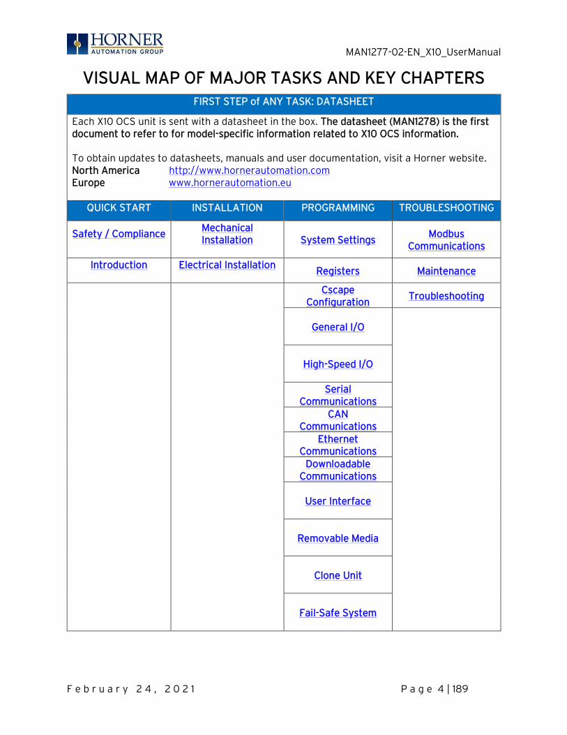
VISUAL MAP OF MAJOR TASKS AND KEY CHAPTERS FIRST STEP of ANY TASK: DATASHEET
Each X10 OCS unit is sent with a datasheet in the box. The datasheet (MAN1278) is the first document to refer to for model-specific information related to X10 OCS information. To obtain updates to datasheets, manuals and user documentation, visit a Horner website. North America http://www.hornerautomation.com Europe www.hornerautomation.eu
QUICK START INSTALLATION PROGRAMMING TROUBLESHOOTING
Safety / Compliance
Mechanical Installation
System Settings
Modbus Communications
Introduction
Electrical Installation
Registers Maintenance
Cscape Configuration
Troubleshooting
General I/O
High-Speed I/O
Serial
Communications CAN
Communications Ethernet
Communications Downloadable
Communications
User Interface
Removable Media
Clone Unit
Fail-Safe System

MAN1277-02-EN_X10_UserManual
F e b r u a r y 2 4 , 2 0 2 1 P a g e 5 | 189
TABLE OF CONTENTS
PREFACE ............................................................................................................................................................2
LIMITED WARRANTY AND LIMITATION OF LIABILITY............................................................................3
ABOUT PROGRAMMING EXAMPLE ..............................................................................................................3
VISUAL MAP OF MAJOR TASKS AND KEY CHAPTERS ......................................................................... 4
TABLE OF CONTENTS .................................................................................................................................... 5
CHAPTER 1: SAFETY / COMPLIANCE .................................................................................................... 10
1.1 Safety Warnings and Guidelines ............................................................................................ 10 1.2 Grounding ..................................................................................................................................... 11 1.3 Compliance ................................................................................................................................... 11
CHAPTER 2: INTRODUCTION ................................................................................................................. 12
2.1 Visual Overview of X10 OCS .................................................................................................... 12 2.2 Where to Find Information about the X10 OCS .................................................................. 14 2.3 Four Main Types of Information are covered in this Manual .......................................... 14 2.4 Manual Index ............................................................................................................................... 14 2.5 Connectivity to the X10 OCS ................................................................................................... 15 2.6 Features of the X10 OCS .......................................................................................................... 16 2.7 Useful Documents and References ....................................................................................... 16
CHAPTER 3: MECHANICAL INSTALLATION ................................................................................... 17
3.1 Mounting Overview ................................................................................................................... 17 3.2 Mounting Procedures (Installed in a Panel Door) .............................................................. 17 3.3 Mounting Clip Locations .......................................................................................................... 18 3.4 Mounting Orientation ............................................................................................................... 18 3.5 Dimensions .................................................................................................................................. 19 3.6 Installation Procedure ............................................................................................................. 20 3.7 Factors Affecting Panel Layout Design and Clearances ................................................. 21 3.8 Clearance / Adequate Space .................................................................................................. 21 3.9 Grounding .................................................................................................................................... 21 3.10 Temperature / Ventilation ..................................................................................................... 22 3.11 Noise ............................................................................................................................................ 22 3.12 Shock and Vibration ................................................................................................................. 22 3.13 Panel Layout Design and Clearance Checklist .................................................................. 22
CHAPTER 4: ELECTRICAL INSTALLATION .................................................................................... 23
4.1 Grounding Definition................................................................................................................ 23 4.2 Ground Specifications ............................................................................................................. 23 4.3 How to Test for Good Ground ............................................................................................... 24 4.4 Primary Power Port ................................................................................................................. 25
CHAPTER 5: SYSTEM SETTINGS AND ADJUSTMENTS .............................................................. 26
5.1 System Menu - Overview ........................................................................................................ 26 5.2 System Menu – Navigation and Editing ............................................................................... 28 5.3 Set Network ............................................................................................................................... 29
MAN1277-02-EN_X10_UserManual
F e b r u a r y 2 4 , 2 0 2 1 P a g e 6 | 189
5.4 Set Network Baud ..................................................................................................................... 30 5.5 View Status ................................................................................................................................. 31 5.6 View Diags .................................................................................................................................. 32 5.7 View Protocols .......................................................................................................................... 34 5.8 Set Fkeys .................................................................................................................................... 35 5.9 Set Serial Ports ......................................................................................................................... 36 5.10 Set Time/Date ........................................................................................................................... 37 5.11 Calibrate Analog ....................................................................................................................... 38 5.12 Set Beeper ................................................................................................................................. 39 5.13 Set Screen .................................................................................................................................. 40 5.14 Removable Media ...................................................................................................................... 41 5.15 Fail – Safe System .................................................................................................................... 42 5.16 Enable AutoRun ........................................................................................................................ 43 5.17 Enable AutoLoad ...................................................................................................................... 44 5.18 Clone Unit ................................................................................................................................... 45 5.19 Load Clone ................................................................................................................................. 46 5.20 Touch Screen Calibration ....................................................................................................... 47
CHAPTER 6: REGISTERS .................................................................................................................... 49
6.1 Register Definitions ................................................................................................................. 49 6.2 Useful %S and %SR registers ............................................................................................... 49 6.3 Register Maps for X10 OCS I/O ............................................................................................. 58 6.4 Resource Limits ........................................................................................................................ 59
CHAPTER 7: CSCAPE CONFIGURATION ......................................................................................... 60
7.1 Overview ..................................................................................................................................... 60 7.2 Cscape Status Bar .................................................................................................................... 60 7.3 Establishing Communications ................................................................................................ 61 7.4 Communicating via MJ1 Serial Port ..................................................................................... 68 7.5 Communicating via On Board Ethernet Port ..................................................................... 69 7.6 Configuration ............................................................................................................................. 73 7.7 Digital / HSC Input Configuration ......................................................................................... 74 7.8 Digital / PWM Output Configuration .................................................................................... 76 7.9 Analog Input Configuration.................................................................................................... 77 7.10 Analog Output Configuration ................................................................................................ 79 7.11 Scaling Analog Inputs .............................................................................................................. 82
CHAPTER 8: GENERAL I/O ................................................................................................................. 84
8.1 Overview ..................................................................................................................................... 84 8.2 Model and I/O Overview .......................................................................................................... 85 8.3 Solid-State Digital Outputs ..................................................................................................... 85 8.4 Relay Outputs ............................................................................................................................ 88 8.5 Model R: Sinking and Sourcing Outputs .............................................................................. 89 8.6 Digital Inputs .............................................................................................................................. 90 8.7 Analog Inputs ............................................................................................................................ 92 8.8 I/O Status and Calibration ...................................................................................................... 92 8.9 RTD Wiring on J3 Connector ................................................................................................. 95 8.10 4x4-20mA Wiring for Input and Output .............................................................................. 96 8.11 Analog Outputs ......................................................................................................................... 97
MAN1277-02-EN_X10_UserManual
F e b r u a r y 2 4 , 2 0 2 1 P a g e 7 | 189
CHAPTER 9: HIGH SPEED I/O (HSC/PWM) ................................................................................... 98
9.1 Overview ..................................................................................................................................... 98 9.2 Glossary of High Speed I/O Terms ....................................................................................... 98 9.3 High Speed Counter (HSC) Functions ................................................................................. 99 9.4 Frequency ................................................................................................................................... 99 9.5 Totalize ..................................................................................................................................... 100 9.6 Pulse ............................................................................................................................................ 101 9.7 Quadrature ................................................................................................................................102 9.8 HSC (High Speed Counter) ................................................................................................... 106 9.9 HSC Functions Register Map ............................................................................................... 106 9.10 Pulse Width Modulation (PWM) Functions ....................................................................... 106 9.11 Normal ....................................................................................................................................... 106 9.12 PWM ............................................................................................................................................ 107 9.13 PWM Output Waveform ........................................................................................................ 108 9.14 PWM Functions Register Map .............................................................................................. 109 9.15 PWM Examples ........................................................................................................................ 109
CHAPTER 10: SERIAL COMMUNICATIONS ....................................................................................... 110
10.1 Overview ..................................................................................................................................... 110 10.2 Port Descriptions ...................................................................................................................... 110 10.3 Wiring—MJ1/MJ2 Serial Ports ................................................................................................ 110 10.4 RS-485 Termination and Biasing .......................................................................................... 111 10.5 Cscape Programming via Serial Port.................................................................................... 111 10.6 Ladder-Controlled Serial Communication .......................................................................... 112 10.7 Configuration via Mini-B USB ................................................................................................ 112
CHAPTER 11: CAN COMMUNICATIONS ............................................................................................ 113
11.1 Overview ..................................................................................................................................... 113 11.2 CAN Port Wiring ........................................................................................................................ 114 11.3 Cscape Programming via CAN .............................................................................................. 114 11.4 Ladder-Controlled CAN Communication ............................................................................ 114 11.5 Using CAN for I/O Expansion (Network I/O) ...................................................................... 115 11.6 CAN and Termination and Bias ............................................................................................. 115
CHAPTER 12: ETHERNET COMMUNICATIONS ................................................................................ 116
12.1 Ethernet Overview ................................................................................................................... 116 12.2 Ethernet Module Protocols and Features........................................................................... 116 12.3 Ethernet System Requirements............................................................................................ 116 12.4 Ethernet Module Specifications ............................................................................................ 117 12.5 Ethernet Module Configuration ............................................................................................ 117 12.6 Ethernet Configuration – IP Parameters ...........................................................................120 12.7 Ethernet Module Protocol Configuration ..........................................................................120
CHAPTER 13: DOWNLOADABLE COMMUNICATION PROTOCOLS ............................................. 121
13.1 Overview ..................................................................................................................................... 121 13.2 Protocol Config ........................................................................................................................ 123 13.3 Network Configuration ........................................................................................................... 124 13.4 Device List and Device Configuration ................................................................................ 126 13.5 Scan List .................................................................................................................................... 127
MAN1277-02-EN_X10_UserManual
F e b r u a r y 2 4 , 2 0 2 1 P a g e 8 | 189
13.6 Data Mapping Configuration (Scan List Entry) ................................................................ 128
CHAPTER 14: USER INTERFACE ........................................................................................................ 130
14.1 Overview .................................................................................................................................... 130 14.2 Screen Specifications ............................................................................................................. 130 14.3 Displaying and Entering Data ................................................................................................ 131 14.4 Numeric keypad ....................................................................................................................... 132 14.5 Screen Navigation ................................................................................................................... 134 14.6 Ladder Based Screen Navigation ........................................................................................ 135 14.7 Touch (Slip) Sensitivity .......................................................................................................... 136 14.8 Alarms ........................................................................................................................................ 137 14.9 Alarm Viewer ............................................................................................................................ 138 14.10 Removable Media ..................................................................................................................... 141 14.11 Screen Saver ............................................................................................................................ 143
CHAPTER 15: REMOVABLE MEDIA .................................................................................................. 144
15.1 Overview ................................................................................................................................... 144 15.2 microSD Cards ......................................................................................................................... 144 15.3 microSD File System .............................................................................................................. 145 15.4 Using the Removable Media Manager ............................................................................... 145 15.5 Using Removable Media to Log Data ................................................................................. 146 15.6 Using Removable Media to Load and Save Applications .............................................. 146 15.7 Using Removable Media to View and Capture Screens ................................................. 147 15.8 Configuration of a Removable Media ................................................................................. 147 15.9 Removable Media (RM) Features—Program Logic.......................................................... 148 15.10 Removable Media (RM) Features— Program Features .................................................. 149 15.11 Removable Media (RM) Features—Graphic/Screen Editor ........................................... 149 15.12 Removable Media Features—Additional Configuration ................................................. 149 15.13 Filenames used with the Removable Media (RM) Function Blocks ............................ 150 15.14 System Registers used with RM............................................................................................ 151 15.15 Safe Removal of Removable Media Card .......................................................................... 152
CHAPTER 16: CLONE UNIT ................................................................................................................. 153
16.1 Overview .................................................................................................................................... 153 16.2 Clone ........................................................................................................................................... 153 16.3 Load Clone ................................................................................................................................ 157
CHAPTER 17: FAIL – SAFE SYSTEM .................................................................................................159
17.1 Overview ....................................................................................................................................159 17.2 Settings ..................................................................................................................................... 160 17.3 Backup / Restore Data .......................................................................................................... 160 17.4 AutoLoad ...................................................................................................................................165 17.5 AutoRun ..................................................................................................................................... 167
CHAPTER 18: MODBUS COMMUNICATIONS .................................................................................. 168
18.1 Modbus Overview ................................................................................................................... 168 18.2 Modbus Slave Overview ........................................................................................................ 168 18.3 Modbus Master Overview ..................................................................................................... 169 18.4 Opening Cscape Help File ...................................................................................................... 170 18.5 Modbus Addressing Table ...................................................................................................... 171
MAN1277-02-EN_X10_UserManual
F e b r u a r y 2 4 , 2 0 2 1 P a g e 9 | 189
CHAPTER 19: MAINTENANCE ............................................................................................................ 172
19.1 Firmware Update Overview .................................................................................................. 172 19.2 How to Check Firmware Revision ........................................................................................ 172 19.3 Firmware Update Details ....................................................................................................... 173 19.4 Firmware Update via microSD card .................................................................................... 175 19.5 Replacing Backup Battery ..................................................................................................... 178
CHAPTER 20: TROUBLESHOOTING / TECHNICAL SUPPORT .................................................... 179
20.1 Connecting to the X10 ............................................................................................................ 179 20.2 Connecting Troubleshooting Checklist (serial port – MJ1 Programming) ................ 180 20.3 Connecting Troubleshooting Checklist (USB Port - Mini B Programming) .............. 180 20.4 Connecting Troubleshooting Checklist (ETN port programming) .............................. 180 20.5 Local Controller and Local I/O .............................................................................................. 181 20.6 Local I/O Troubleshooting Checklist ................................................................................... 181 20.7 CsCAN Network ......................................................................................................................... 181 20.8 CsCAN Network Troubleshooting Checklist ...................................................................... 182 20.9 Basic Troubleshooting ............................................................................................................ 183 20.10 Technical Support Contacts .................................................................................................. 183
CHANGE LOG............................................................................................................................................ 184
MAIN INDEX .............................................................................................................................................. 185

MAN1277-02-EN_X10_UserManual
F e b r u a r y 2 4 , 2 0 2 1 P a g e 10 | 189
CHAPTER 1: SAFETY / COMPLIANCE
1.1 Safety Warnings and Guidelines
When found on the product, the following symbols specify:
Warning: Consult user documentation. Warning: Electrical Shock Hazard.
WARNING – EXPLOSION HAZARD: Do not disconnect equipment unless power has been switched off or the area is known to be non-hazardous WARNING: To avoid the risk of electric shock or burns, always connect the safety (or earth) ground before making any other connections. WARNING: To reduce the risk of fire, electrical shock, or physical injury it is strongly recommended to fuse the voltage measurement inputs. Be sure to locate fuses as close to the source as possible. WARNING: Replace fuse with the same type and rating to provide protection against risk of fire and shock hazards. WARNING: In the event of repeated failure, do not replace the fuse again as a repeated failure indicates a defective condition that will not clear by replacing the fuse. WARNING: EXPLOSION HAZARD—Substitution of components may impair suitability for Class I, Division 2. WARNING: The USB parts are for operational maintenance only. Do not leave permanently connected unless area is known to be non-hazardous. WARNING: EXPLOSION HAZARD—BATTERIES MUST ONLY BE CHANGED IN AN AREA KNOWN TO BE NON-HAZARDOUS WARNING: BATTERY MAY EXPLODE IF MISTREATED. DO NOT RECHARD, DISASSEMBLE, OR DISPOSE OF IN FIRE. WARNING: Only qualified electrical personnel familiar with the construction and operation of this equipment and the hazards involved should install, adjust, operate, or service this equipment. Read and understand this manual and other applicable manuals in their entirety before proceeding. Failure to observe this precaution could result in severe bodily injury or loss of life. WARNING: If the equipment is used in a manner not specified by Horner APG, the protection provided by the equipment may be impaired.

MAN1277-02-EN_X10_UserManual
F e b r u a r y 2 4 , 2 0 2 1 P a g e 11 | 189
• All applicable codes and standards need to be followed in the installation of this product. • For I/O wiring (discrete), use the following wire type or equivalent: Belden 9918, 18
AWG, or larger.
Adhere to the following safety precautions whenever any type of connection is made to the module.
a. Connect the green safety (earth) ground first before making any other connections. b. When connecting to electric circuits or pulse-initiating equipment, open their related
breakers. Do not make connections to live power lines. c. Make connections to the module first; then connect to the circuit to be monitored. d. Route power wires in a safe manner in accordance with good practice and local codes. e. Wear proper personal protective equipment including safety glasses and insulated
gloves when making connections to power circuits. f. Ensure hands, shoes, and floors are dry before making any connection to a power line. g. Make sure the unit is turned OFF before making connection to terminals. Make sure all
circuits are de-energized before making connections. h. Before each use, inspect all cables for breaks or cracks in the insulation. Replace
immediately if defective.
1.2 Grounding
Grounding is covered in various chapters within this manual.
1.3 Compliance
To check for compliance and updates, visit the Horner website. North America https://hornerautomation.com Europe www.hornerautomation.eu
MAN1277-02-EN_X10_UserManual
F e b r u a r y 2 4 , 2 0 2 1 P a g e 12 | 189
CHAPTER 2: INTRODUCTION
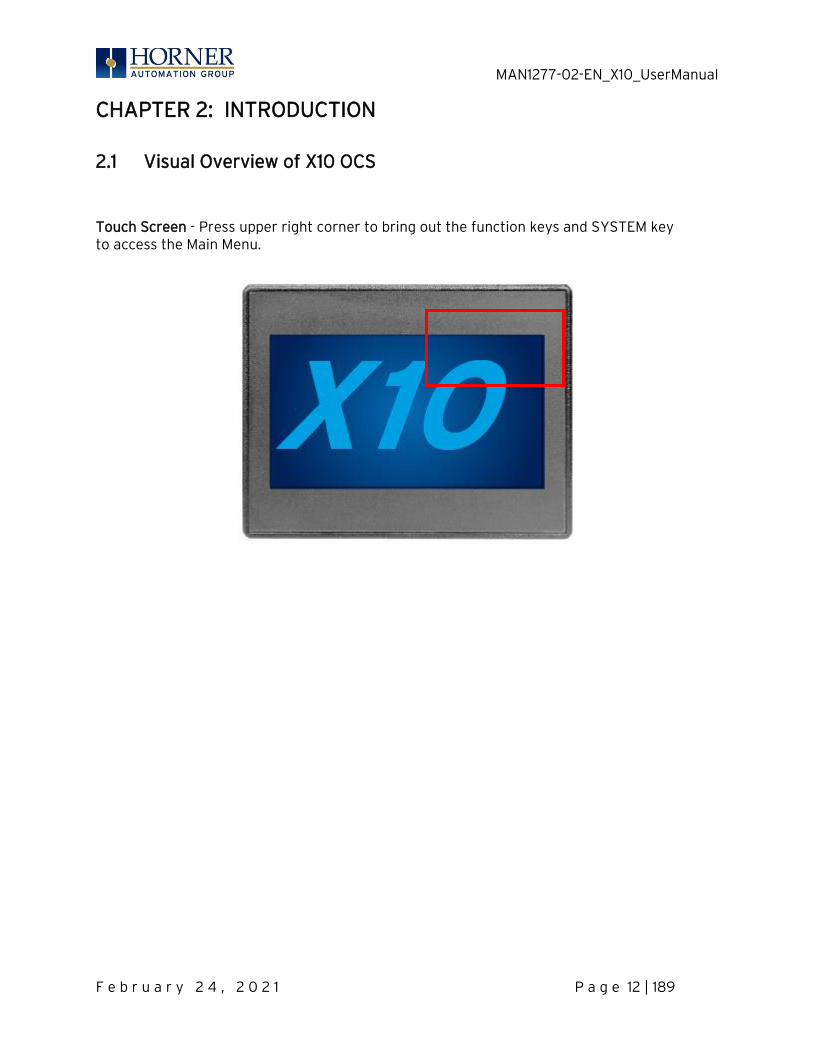
2.1 Visual Overview of X10 OCS
Touch Screen - Press upper right corner to bring out the function keys and SYSTEM key to access the Main Menu.

MAN1277-02-EN_X10_UserManual
F e b r u a r y 2 4 , 2 0 2 1 P a g e 13 | 189
Port Connections
1. Touch Screen 2. High-capacity microSD Slot, RS232/RS485 Serial Connector, CAN port (via RJ45),
CAN Port (Ethernet) 3. USB Mini-B Port 4. Analog I/O, DC Inputs, DC Outputs 5. DC Power
Figure 2.1 – Visual Overview of the X10Error! Bookmark not defined.

MAN1277-02-EN_X10_UserManual
F e b r u a r y 2 4 , 2 0 2 1 P a g e 14 | 189
2.2 Where to Find Information about the X10 OCS
a) Datasheet [MAN1278] – The datasheet is the first document to refer to for key information related to specific X10 OCS models. b) User Manual [MAN1279] – This manual provides general information that is common to X10 OCS models and can be downloaded from our website. Visit the Horner website to obtain user documentation and updates. North America http://www.hornerautomation.com Europe www.hornerautomation.eu
2.3 Four Main Types of Information are covered in this Manual
a) Safety and Installation guidelines / instructions (Mechanical and Electrical) b) Descriptions of hardware features – Serial ports, Removable Media,
Communications, etc. c) Configuration and Use of the X10 OCS d) Maintenance and Support
2.4 Manual Index
Major topics of interest may be found in the Index near the end of this manual.
MAN1277-02-EN_X10_UserManual
F e b r u a r y 2 4 , 2 0 2 1 P a g e 15 | 189
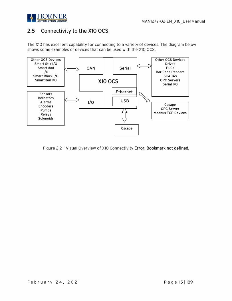
2.5 Connectivity to the X10 OCS
The X10 has excellent capability for connecting to a variety of devices. The diagram below shows some examples of devices that can be used with the X10 OCS.
Figure 2.2 – Visual Overview of X10 Connectivity Error! Bookmark not defined.
CAN
Serial
I/O
X10 OCS
Other OCS Devices Drives PLCs
Bar Code Readers SCADAs
OPC Servers Serial I/O
Sensors Indicators
Alarms Encoders
Pumps Relays
Solenoids
Other OCS Devices Smart Stix I/O
SmartMod I/O
Smart Block I/O SmartRail I/O
USB
Cscape
Ethernet
Cscape OPC Server
Modbus TCP Devices

MAN1277-02-EN_X10_UserManual
F e b r u a r y 2 4 , 2 0 2 1 P a g e 16 | 189
2.6 Features of the X10 OCS
The X10 OCSs are all-in-one industrial control devices. They combine control, user interface, I/O and networking into a single, integrated package. Unique features of the X10 OCS include the following.
• Small, sleek profile saves space and resources. • Physical Specifications
o mm: 167.818 tall x 264.998 wide x 52.07 deep o in: 6.607 tall x 10.4333 wide x 2.05 deep o 39 oz. / 1105.6g
• Bright color display • Display of complex graphical objects including trends, gauges, meters and animations • Advanced control capabilities including floating point, multiple auto-tuning PID loops
and string handling capabilities • Intuitive interface • Removable media for storage of programs, data logging, or screen captures • CsCAN networking port for communication with remote I/O, other controllers or PCs • Cscape programming software that allows all aspects of the X10 to be programmed
and configured from one integrated application • Fail – Safe System which allows an application to continue running in the event of
“Soft” failures such as (Battery power loss or Battery Backed register RAM / Application flash corruption)
• Clone Unit allows the user to “clone” the OCS. This feature “clones” application program and unit settings stored in Battery backed RAM of an OCS. It can then be used to clone a different OCS (but must be the exact same model).
• Suited for most applications across a diverse range of industries
2.7 Useful Documents and References
Visit our website, to obtain user documentation, supplemental documents, certificates, and other documentation. North America https://hornerautomation.com Europe www.hornerautomation.eu

MAN1277-02-EN_X10_UserManual
F e b r u a r y 2 4 , 2 0 2 1 P a g e 17 | 189
CHAPTER 3: MECHANICAL INSTALLATION NOTE: The datasheet is the first document to refer to for model-specific installation information. Visit the Horner websites to obtain datasheets, user documentation, and updates.
3.1 Mounting Overview
The mechanical installation greatly affects the operation, safety, and appearance of the system. Information is provided to mechanically install the unit such as cut-out sizes, mounting procedures, and other recommendations for the proper mechanical installation of the unit.
3.2 Mounting Procedures (Installed in a Panel Door)
Once the panel design has been completed using the criteria and suggestions in the following sections, use the following steps to panel mount the X10 OCS.
NOTE: Unit comes with composite clips, which are tested for typical wash down, shock, and vibration. If metal mounting clips are needed, they can be ordered at the Horner Automation website.
1. Carefully locate an appropriate place to mount the X10. Be sure to leave enough room at the top of the unit for insertion. Remove the microSD card to prevent damage to the panel edge.
2. Carefully cut the host panel per the measurements found in the datasheet. Dimensions can also be found below in the Panel Cutout section. If the opening is too large, water may leak into the enclosure, potentially damaging the unit. If the opening is too small, the OCS may not fit through the hole without damage.
3. Remove any burrs and/or shape edges and ensure the panel is not warped in the cutting process.
4. Make sure the gasket is installed on the X10 OCS and is free from dust and debris. Check that the corners of the gasket are secure.
5. Pass the unit through the panel. 6. Insert each of the four (4) mounting clips into the slots in the X10 OCS case. One
composite plastic clip should be installed on each corner. Lightly tighten each screw so the clip is held in place.
7. Tighten the screws on the clips such that the gasket is compressed against the panel. Recommended torque is 2-3 in-lbs (0.23 – 0.34 Nm). If metal mounting clips are used in place of the plastic composite mounting clips, the recommended torque is 4-8 in-lbs (0.45-0.90 Nm).
8. Connect communications cables to the serial port, USB ports, and CAN port as required.
Clip Description Part Number Composite Plastic Clip 400B178-R2.0 Metal Clip HE500ACC604
MAN1277-02-EN_X10_UserManual
F e b r u a r y 2 4 , 2 0 2 1 P a g e 18 | 189
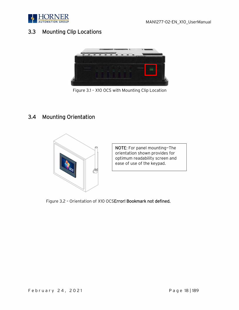
3.3 Mounting Clip Locations
Figure 3.1 – X10 OCS with Mounting Clip Location
3.4 Mounting Orientation
Figure 3.2 – Orientation of X10 OCSError! Bookmark not defined.
NOTE: For panel mounting—The orientation shown provides for optimum readability screen and ease of use of the keypad.

MAN1277-02-EN_X10_UserManual
F e b r u a r y 2 4 , 2 0 2 1 P a g e 19 | 189
3.5 Dimensions
For installations requiring NEMA 4X liquid and dust protection, the panel cutout should be cut with a tolerance of +0.5mm / -0mm.
Figure 3.4 – X10 OCS DimensionsError! Bookmark not defined.

MAN1277-02-EN_X10_UserManual
F e b r u a r y 2 4 , 2 0 2 1 P a g e 20 | 189
3.6 Installation Procedure
• This equipment is panel mounted and is meant to be installed in an enclosure suitable for the environment, such that the back of the equipment is only accessible with the use of a tool.
• This equipment is suitable for use in Class I, Division 2, Groups A, B, C and D; Class II, Division 2 Groups F and G; and Class III Hazardous Locations or Non-Hazardous Locations only.
• The X10 utilizes a clip installation method to ensure a robust and watertight seal to the enclosure. Follow the steps below for the proper installation and operation of the unit.
1. Carefully locate an appropriate place to mount the X10. Be sure to leave enough room at the top of the unit for insertion and removal of the microSD™ card.
2. Carefully cut the host panel per the diagram, creating a 175mm x 131.9mm (with a tolerance of +/- 1.0mm) opening into which the X10 is to be installed. If the opening is too large, water may leak into the enclosure, potentially damaging the unit. If the opening is too small, the OCS may not fit through the hole without damage.
3. Remove any burrs/sharp edges and ensure the panel is not warped in the cutting process.
4. Install and tighten the four mounting clips (provided in the box) until the gasket forms a tight seal. For standard composite mounting clips (included with product). NOTE: Torque Rating is 2-3 in-lbs (0.23-0.34 Nm). For optional metal mounting clips, use a torque rating of 4-8 in-lbs (0.45-0.90 Nm).
5. Connect communications cables to the serial port, USB ports, and CAN port as required.

MAN1277-02-EN_X10_UserManual
F e b r u a r y 2 4 , 2 0 2 1 P a g e 21 | 189
3.7 Factors Affecting Panel Layout Design and Clearances
The designer of a panel layout needs to assess the requirements of a particular system and to consider the following design factors.
3.8 Clearance / Adequate Space
Install devices to allow sufficient clearance to open and close the panel door.
Table 3.1 – Minimum Clearance Requirements for Panel Box and DoorError! Bookmark not defined.
Minimum Distance – between base of device and sides of cabinet.
2” (50.80mm)
Minimum Distance – between base of device and wiring ducts.
1.5” (38.10mm)
Minimum Distance - between bases of each device if more than one device is installed in panel box or on door.
4” between bases of each device (101.60mm)
Minimum Distance – between device and closed door when door is closed. (Be sure to allow enough depth for the OCS.)
2” (50.80mm)
3.9 Grounding
Panel Box: The panel box needs to be properly connected to earth ground to provide a good common ground reference.
Panel Door: Tie a low impedance ground strap between the panel box and the panel door to ensure that they have the same ground reference.
WARNING: It is important to follow the requirements of the panel manufacturer and to follow all applicable electrical codes and standards. all applicable electrical codes and standards.
WARNING: Be sure to meet the ground requirements of the panel manufacturer and also meet applicable electrical codes and standards.

MAN1277-02-EN_X10_UserManual
F e b r u a r y 2 4 , 2 0 2 1 P a g e 22 | 189
3.10 Temperature / Ventilation
Ensure that the panel layout design allows for adequate ventilation and maintains the specified ambient temperature range. Consider the impact on the design of the panel layout if operating at the extreme ends of the ambient temperature range. For example, if it is determined that a cooling device is required, allow adequate space and clearances for the device in the panel box or on the panel door.
3.11 Noise
Consider the impact on the panel layout design and clearance requirements if noise suppression devices are needed. Be sure to maintain an adequate distance between the X10 OCS and noisy devices such as relays, motor starters, etc. For details on output protection, especially when using contactors and solenoids, see MAN0962 on “Spark Quenchers”.
3.12 Shock and Vibration
The X10 OCS has been designed to operate in typical industrial environments that may inflict some shock and vibration on the unit. For applications that may inflict excessive shock and vibration, please use proper dampening techniques or relocate the X10 OCS to a location that minimizes shock and/or vibration.
3.13 Panel Layout Design and Clearance Checklist
The following list provides highlights of panel layout design factors:
____Meets the electrical code and applicable standards for proper grounding, etc.? ____Meets the panel manufacturer’s requirements for grounding, etc.? ____Is the panel box properly connected to earth ground? Is the panel door properly grounded?
Has the appropriate procedure been followed to properly ground the devices in the panel box and on the panel door?
____Are minimum clearance requirements met? Can the panel door be easily opened and closed? Is there adequate space between device bases as well as the sides of the panel and wiring ducts?
____Is the panel box deep enough to accommodate the X10 OCS? ____Is there adequate ventilation? Is the ambient temperature range maintained? Are cooling
or heating devices required? ____Are noise suppression devices or isolation transformers required? Is there adequate
distance between the base of the X10 OCS and noisy devices such as relays or motor starters? Ensure that power and signal wires are not routed in the same conduit.
____Are there other requirements that impact the system, which need to be considered?

MAN1277-02-EN_X10_UserManual
F e b r u a r y 2 4 , 2 0 2 1 P a g e 23 | 189
CHAPTER 4: ELECTRICAL INSTALLATION NOTE: The datasheet [MAN1156] is the first document you need to refer to for model-specific information related to X10 OCS. Visit our website to obtain datasheets, user documentation, and updates. North America https://hornerautomation.com Europe www.hornerautomation.eu
4.1 Grounding Definition
Ground: The term Ground is defined as a conductive connection between a circuit or piece of equipment and the earth. Grounds are fundamentally used to protect an application from harmful interference causing either physical damage such as by lightning or voltage transients or from circuit disruption often caused by radio frequency interference (RFI).
4.2 Ground Specifications
Ideally, a ground resistance measurement from equipment to earth ground is 0Ω. In reality, it typically is higher. The U.S. National Electrical Code (NEC) states the resistance to ground shall not exceed 25Ω. Horner Automation recommends less than 15Ω resistance from our equipment to ground. Resistance greater than 25Ω can cause undesirable or harmful interference to the device.

MAN1277-02-EN_X10_UserManual
F e b r u a r y 2 4 , 2 0 2 1 P a g e 24 | 189
4.3 How to Test for Good Ground
In order to test ground resistance, a Ground Resistance Tester must be used. A typical Ground Resistance Meter Kit contains a meter, two or three wire leads, and two ground rods. Instructions are supplied for either a two-point or a three-point ground test.
Figure 4.1 – Two-Point Ground Connection Test
METAL WATER PIPE OROTHER GOOD GROUND
GROUND ROD
GROUNDDISCONNECTEDFROM SERVICE
GROUND RESISTANCE METER

MAN1277-02-EN_X10_UserManual
F e b r u a r y 2 4 , 2 0 2 1 P a g e 25 | 189
4.4 Primary Power Port
NOTE: The Primary Power Range is 9-30VDC.
DC Input / Frame
• Solid/Stranded Wire: 12-24 awg (2.5-0.2mm). • Strip length: 0.28” (7mm). • Torque, Terminal Hold-Down Screws: 4.5 – 7 in-lbs (0.50 – 0.78 N-m). • DC- is internally connected to I/O V but is isolated from CAN V-. A Class 2 power supply
must be used.
POWER UP
1. OPTION: Attach ferrite core with a minimum of two turns of the DC+ and DC- signals from the DC supply that is powering the controllers.
2. Connect to earth ground.
NOTE: Refer to datasheet for power specifications.
MAN1277-02-EN_X10_UserManual
F e b r u a r y 2 4 , 2 0 2 1 P a g e 26 | 189
CHAPTER 5: SYSTEM SETTINGS AND ADJUSTMENTS
5.1 System Menu - Overview
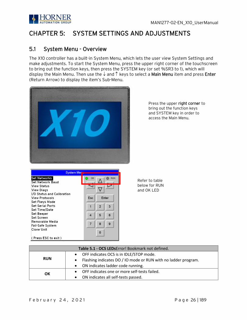
The X10 controller has a built-in System Menu, which lets the user view System Settings and make adjustments. To start the System Menu, press the upper right corner of the touchscreen to bring out the function keys, then press the SYSTEM key (or set %SR3 to 1), which will display the Main Menu. Then use the and keys to select a Main Menu item and press Enter (Return Arrow) to display the item’s Sub-Menu.
Table 5.1 - OCS LEDsError! Bookmark not defined.
RUN • OFF indicates OCS is in IDLE/STOP mode.
• Flashing indicates DO / IO mode or RUN with no ladder program.
• ON indicates ladder code running.
OK • OFF indicates one or more self-tests failed.
• ON indicates all self-tests passed.
Press the upper right corner to bring out the function keys and SYSTEM key in order to access the Main Menu.
Refer to table below for RUN and OK LED information.
MAN1277-02-EN_X10_UserManual
F e b r u a r y 2 4 , 2 0 2 1 P a g e 27 | 189
Error! Bookmark not defined.
Sub-Menus
Sub-Menus
Network Ok?: No
Network ID: 1
CAN Termination: No
MAC ID: 00:E0:C4:E3:BD
IP Address: 192.168.254.128
Network Mask: 255.255.255.0
Gateway: 0.0.0.0
Model: HE-X10
OCS Mode: Idle
Scan Rate(mS): 0.0
Lcl Net Use(%): 0.0
All Net Use(%): 0.0
Firmware Rev: 14.18
FPGA Rev: 0.3
Boot Rev: 1.07
Self-Test: Ok
Ladder Size: 2
Config Size: 8
Graphics Sz: 8
String Size: 8
Bitmap Size: 8
Text Tbl Size: 8
Font Tbl Size: 8
Protocol Size: 8
SMS File Size: 8
Battery Volts 1.23
CPU Temp: 99.0
Logic Error: Ok
User Program: Ok
User Graphics: Ok
W-Dog Trips: 0
Net Errors: 0
Network State: Ok
Network ID: Ok
Dup Net ID: Ok
Clock Error: Ok
I/O System: Ok
Battery: Ok
Calibrate Analog
I1-12: XXXXXXXXXXXX
Q1-12: XXXXXXXXXXXX
AI1: XXXXX AI2: XXXXX
AI3: XXXXX AI4: XXXXX
AQ1: XXXXX AQ2: XXXXX
Calibrate: Channel 1
Mode: 0-20mA
Input Value: xxxmA
Low Cal: OK
High Cal: OK
Directions: Apply 0mA
press Accept.
MJ1:
(None Loaded)
MJ2:
(None Loaded)
COM:
(None Loaded)
Fkeys: Momentary
Sys-Fn enable: Yes
( Use to adjust )
Dflt Pgm Port MJ1-232
MJ2 RS485 Bias No
( Use to adjust )
Time: 10:21:36
Date: 28-Jun-2009
Day: Thursday
( Use to adjust )
( each field )
Saver enable: Yes
Timeout(min): 15
Popup Status: Off
Update Time(mS): 5
Update time sets the
maximum time used by
graphics in the logic
scan.
Media Directory
Media Card Not Present
Clone Unit
Directory Empty
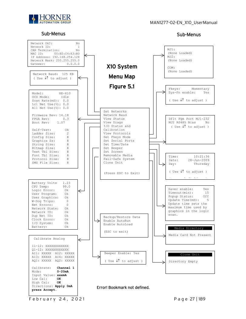
Set Networks
Network Baud
View Status
View Diags
I/O Status and
Calibration
View Protocols
Set Fkeys Mode
Set Serial Ports
Set Time/Date
Set Beeper
Set Screen
Removable Media
Fail-Safe System
Clone Unit
(Press ESC to Exit)
Backup/Restore Data
Enable AutoRun
Enable AutoLoad
(ESC to exit)
Beeper Enable: Yes
( Use to adjust )
X10 System
Menu Map
Figure 5.1
Network Baud: 125 KB
( Use to adjust )
MAN1277-02-EN_X10_UserManual
F e b r u a r y 2 4 , 2 0 2 1 P a g e 28 | 189
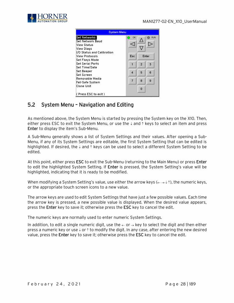
5.2 System Menu – Navigation and Editing
As mentioned above, the System Menu is started by pressing the System key on the X10. Then, either press ESC to exit the System Menu, or use the and keys to select an item and press Enter to display the item’s Sub-Menu.
A Sub-Menu generally shows a list of System Settings and their values. After opening a Sub-Menu, if any of its System Settings are editable, the first System Setting that can be edited is highlighted. If desired, the and keys can be used to select a different System Setting to be edited. At this point, either press ESC to exit the Sub-Menu (returning to the Main Menu) or press Enter to edit the highlighted System Setting. If Enter is pressed, the System Setting’s value will be highlighted, indicating that it is ready to be modified. When modifying a System Setting’s value, use either the arrow keys ( → ), the numeric keys, or the appropriate touch screen icons to a new value. The arrow keys are used to edit System Settings that have just a few possible values. Each time the arrow key is pressed, a new possible value is displayed. When the desired value appears, press the Enter key to save it; otherwise press the ESC key to cancel the edit. The numeric keys are normally used to enter numeric System Settings.
In addition, to edit a single numeric digit, use the or → key to select the digit and then either press a numeric key or use or to modify the digit. In any case, after entering the new desired value, press the Enter key to save it; otherwise press the ESC key to cancel the edit.
MAN1277-02-EN_X10_UserManual
F e b r u a r y 2 4 , 2 0 2 1 P a g e 29 | 189
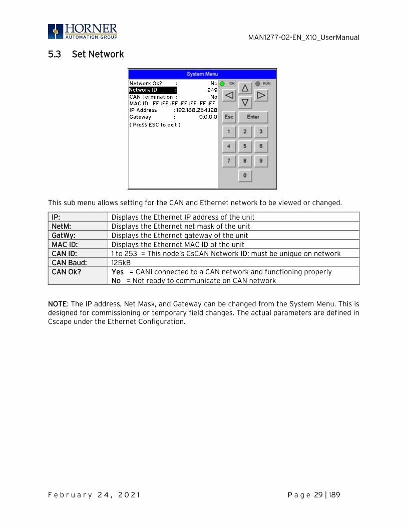
5.3 Set Network
This sub menu allows setting for the CAN and Ethernet network to be viewed or changed.
IP: Displays the Ethernet IP address of the unit NetM: Displays the Ethernet net mask of the unit GatWy: Displays the Ethernet gateway of the unit MAC ID: Displays the Ethernet MAC ID of the unit CAN ID: 1 to 253 = This node’s CsCAN Network ID; must be unique on network CAN Baud: 125kB CAN Ok? Yes = CAN1 connected to a CAN network and functioning properly
No = Not ready to communicate on CAN network
NOTE: The IP address, Net Mask, and Gateway can be changed from the System Menu. This is designed for commissioning or temporary field changes. The actual parameters are defined in Cscape under the Ethernet Configuration.
MAN1277-02-EN_X10_UserManual
F e b r u a r y 2 4 , 2 0 2 1 P a g e 30 | 189
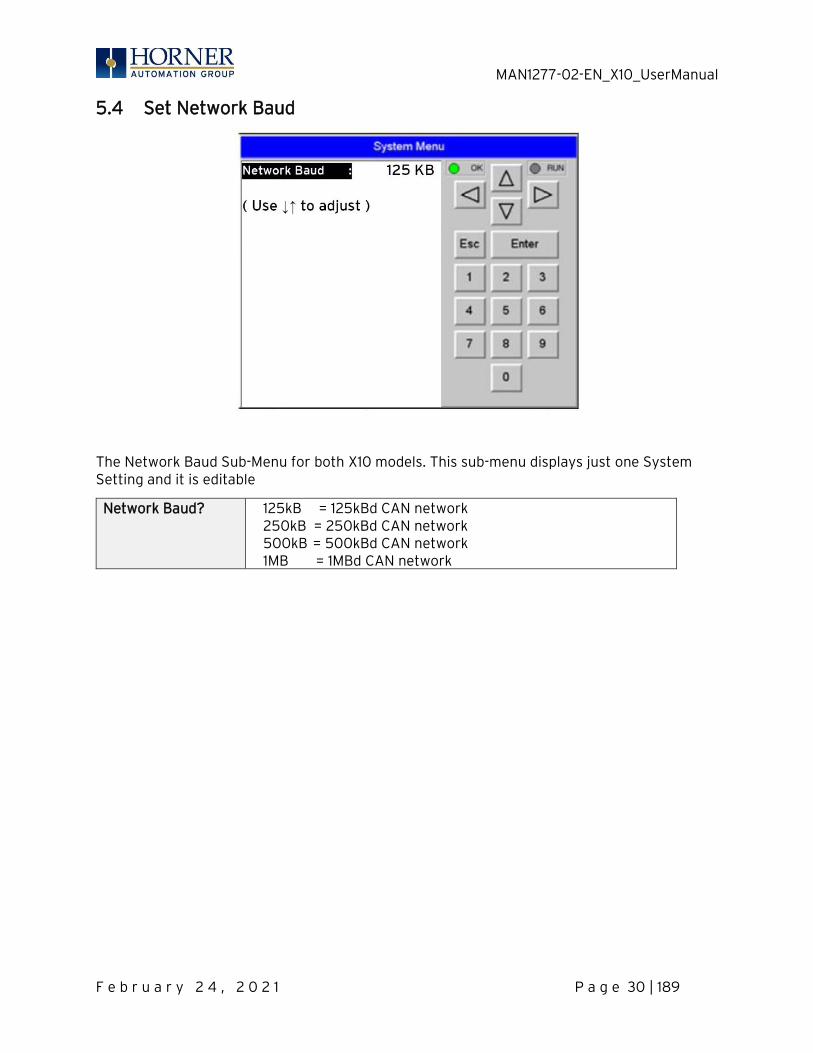
5.4 Set Network Baud
The Network Baud Sub-Menu for both X10 models. This sub-menu displays just one System Setting and it is editable
Network Baud? 125kB = 125kBd CAN network 250kB = 250kBd CAN network 500kB = 500kBd CAN network 1MB = 1MBd CAN network
MAN1277-02-EN_X10_UserManual
F e b r u a r y 2 4 , 2 0 2 1 P a g e 31 | 189
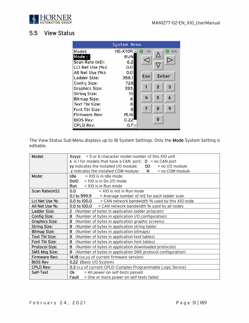
5.5 View Status
The View Status Sub-Menu displays up to 18 System Settings. Only the Mode System Setting is editable.
Model: Xxyyz = 5 or 6 character model number of this X10 unit x is 1 for models that have a CAN port; 0 = no CAN port yy indicates the installed I/O module; 00 = no I/O module z indicates the installed COM module; N = no COM module
Mode: Idle = X10 is in Idle mode DoIO = X10 is in Do I/O mode Run = X10 is in Run mode
Scan Rate(mS): 0.0 = X10 is not in Run mode 0.1 to 999.9 = Average number of mS for each ladder scan
Lcl Net Use %: 0.0 to 100.0 = CAN network bandwidth % used by this X10 node All Net Use %: 0.0 to 100.0 = CAN network bandwidth % used by all nodes Ladder Size: 2 (Number of bytes in application ladder program) Config Size: 8 (Number of bytes in application I/O configuration) Graphics Size: 8 (Number of bytes in application graphic screens) String Size: 8 (Number of bytes in application string table) Bitmap Size: 8 (Number of bytes in application bitmaps) Text Tbl Size: 8 (Number of bytes in application text tables) Font Tbl Size: 8 (Number of bytes in application font tables) Protocol Size: 8 (Number of bytes in application downloaded protocols) SMS Msg Size: 8 (Number of bytes in application SMS protocol configuration) Firmware Rev: 14.18 (xx.yy of current firmware version) BIOS Rev 0.22 (Basic I/O System) CPLD Rev: 0.3 (x.y of current CPLD—Complex Programmable Logic Device) Self-Test Ok = All power-on self-tests passed
Fault = One or more power-on self-tests failed
MAN1277-02-EN_X10_UserManual
F e b r u a r y 2 4 , 2 0 2 1 P a g e 32 | 189
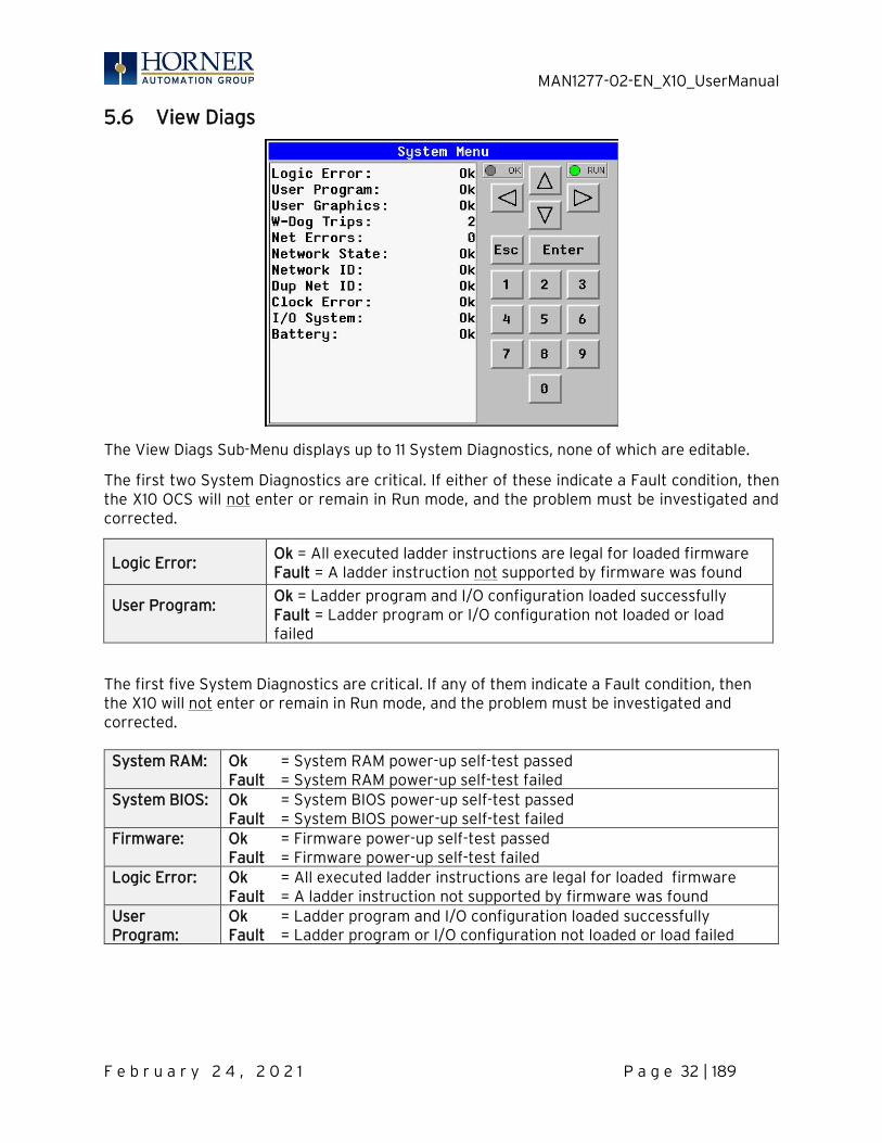
5.6 View Diags
The View Diags Sub-Menu displays up to 11 System Diagnostics, none of which are editable.
The first two System Diagnostics are critical. If either of these indicate a Fault condition, then the X10 OCS will not enter or remain in Run mode, and the problem must be investigated and corrected.
Logic Error: Ok = All executed ladder instructions are legal for loaded firmware Fault = A ladder instruction not supported by firmware was found
User Program:
Ok = Ladder program and I/O configuration loaded successfully Fault = Ladder program or I/O configuration not loaded or load failed
The first five System Diagnostics are critical. If any of them indicate a Fault condition, then the X10 will not enter or remain in Run mode, and the problem must be investigated and corrected. System RAM: Ok = System RAM power-up self-test passed
Fault = System RAM power-up self-test failed System BIOS: Ok = System BIOS power-up self-test passed
Fault = System BIOS power-up self-test failed Firmware: Ok = Firmware power-up self-test passed
Fault = Firmware power-up self-test failed Logic Error: Ok = All executed ladder instructions are legal for loaded firmware
Fault = A ladder instruction not supported by firmware was found User Program:
Ok = Ladder program and I/O configuration loaded successfully Fault = Ladder program or I/O configuration not loaded or load failed

MAN1277-02-EN_X10_UserManual
F e b r u a r y 2 4 , 2 0 2 1 P a g e 33 | 189
The last nine System Diagnostics are informational. If any of them indicate a Warning condition, then the X10 can still enter and remain in Run mode, but the problem should be investigated and corrected.
User Graphics Ok = Application graphics objects loaded successfully Fault = Application graphics objects not loaded or load failed
W-Dog Trips 0 = Watchdog timer has not tripped since the last power-up x = Number of times watchdog timer has tripped
Net Errors 0 = No CAN network bus-off errors have occurred x = Number of CAN network bus-off errors that have occurred
Network State Ok = At least one other node was found on the CAN network Warning = No other nodes were found on the CAN network
Network ID Ok = This node’s CAN Network ID is in the range 1 to 253 Warning = This node’s CAN Network ID was out of range at power-up
Dup Net ID Ok = This node’s Network ID is unique on the CAN network Warning = This node’s Network ID is duplicated in another node
Clock Error Ok = Time and date have been set Warning = Time and date need to be set
I/O System Ok = I/O configuration matches the installed I/O and COM modules Warning = I/O configuration needs updating to match installed modules
Battery Ok = Backup battery operating properly Warning = Backup battery needs to be replaced
MAN1277-02-EN_X10_UserManual
F e b r u a r y 2 4 , 2 0 2 1 P a g e 34 | 189
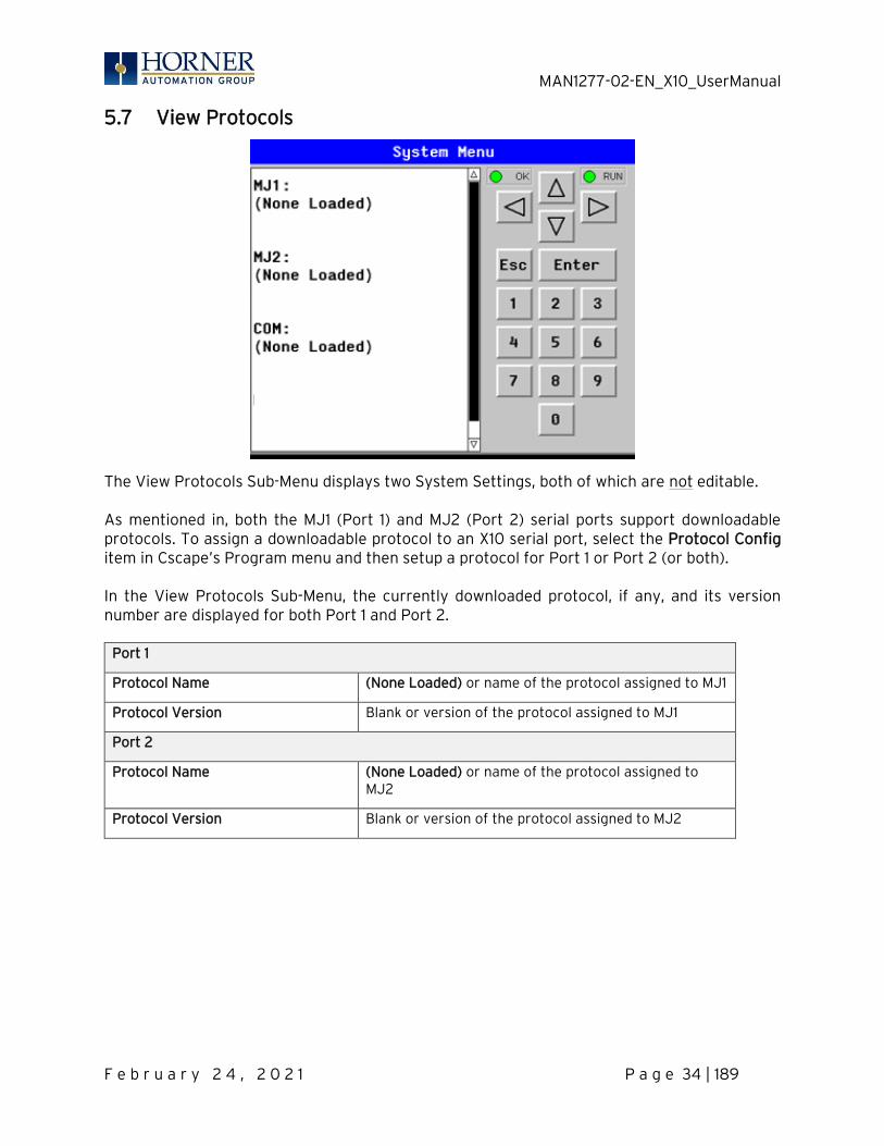
5.7 View Protocols
The View Protocols Sub-Menu displays two System Settings, both of which are not editable. As mentioned in, both the MJ1 (Port 1) and MJ2 (Port 2) serial ports support downloadable protocols. To assign a downloadable protocol to an X10 serial port, select the Protocol Config item in Cscape’s Program menu and then setup a protocol for Port 1 or Port 2 (or both). In the View Protocols Sub-Menu, the currently downloaded protocol, if any, and its version number are displayed for both Port 1 and Port 2.
Port 1
Protocol Name (None Loaded) or name of the protocol assigned to MJ1
Protocol Version Blank or version of the protocol assigned to MJ1
Port 2
Protocol Name (None Loaded) or name of the protocol assigned to MJ2
Protocol Version Blank or version of the protocol assigned to MJ2
MAN1277-02-EN_X10_UserManual
F e b r u a r y 2 4 , 2 0 2 1 P a g e 35 | 189
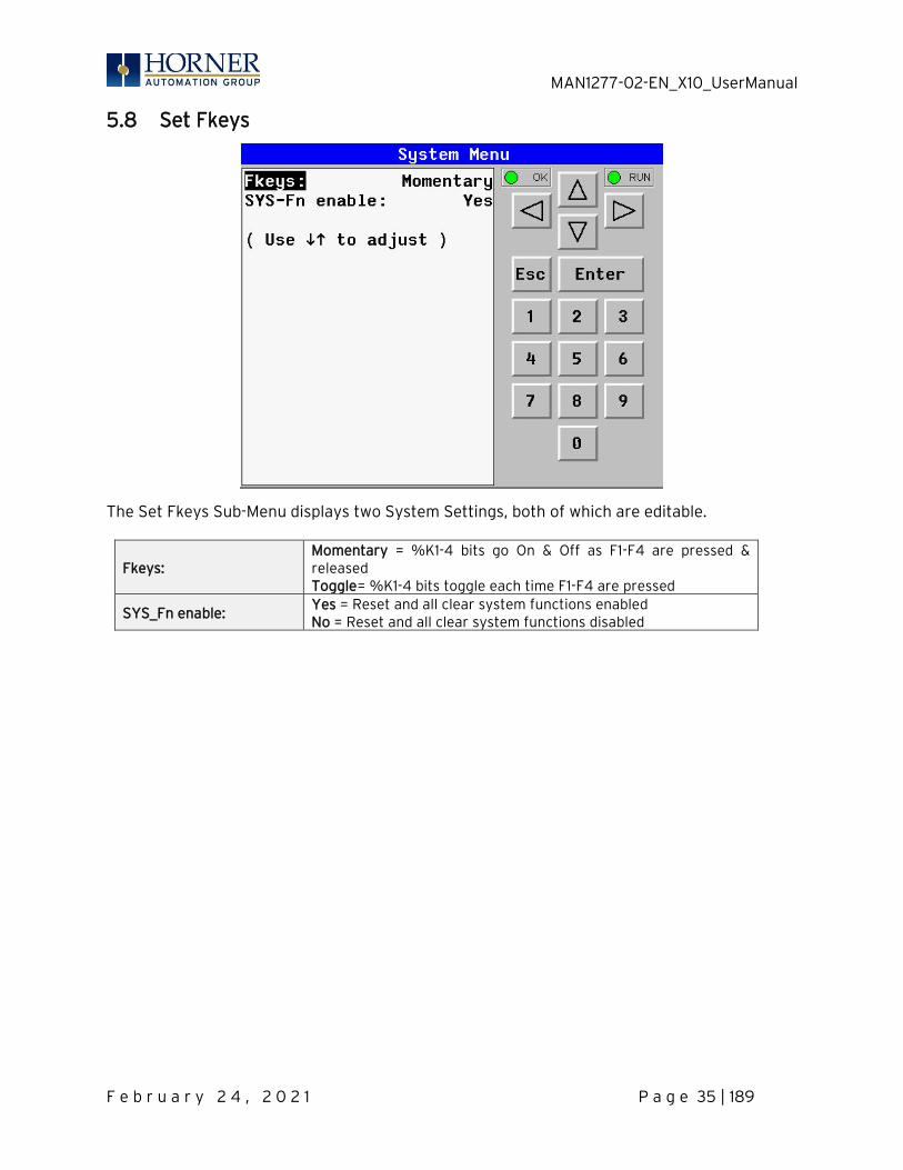
5.8 Set Fkeys
The Set Fkeys Sub-Menu displays two System Settings, both of which are editable.
Fkeys: Momentary = %K1-4 bits go On & Off as F1-F4 are pressed & released Toggle= %K1-4 bits toggle each time F1-F4 are pressed
SYS_Fn enable: Yes = Reset and all clear system functions enabled No = Reset and all clear system functions disabled
MAN1277-02-EN_X10_UserManual
F e b r u a r y 2 4 , 2 0 2 1 P a g e 36 | 189
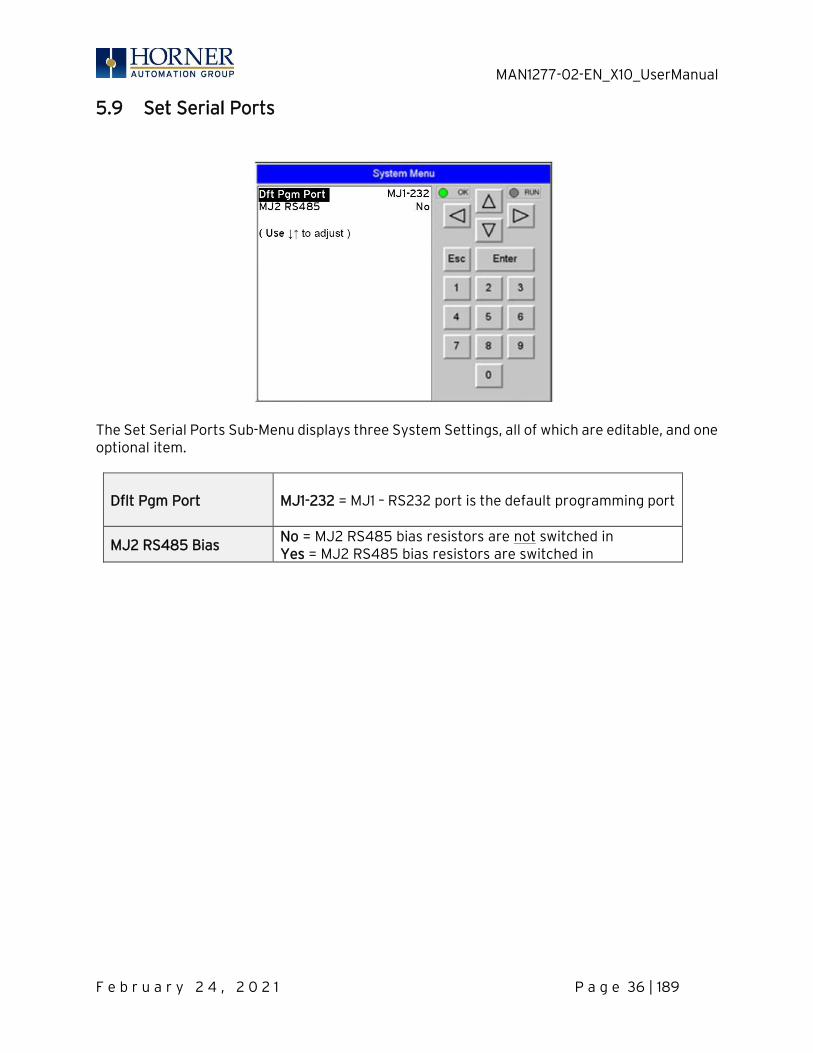
5.9 Set Serial Ports
The Set Serial Ports Sub-Menu displays three System Settings, all of which are editable, and one optional item.
Dflt Pgm Port MJ1-232 = MJ1 – RS232 port is the default programming port
MJ2 RS485 Bias No = MJ2 RS485 bias resistors are not switched in Yes = MJ2 RS485 bias resistors are switched in
MAN1277-02-EN_X10_UserManual
F e b r u a r y 2 4 , 2 0 2 1 P a g e 37 | 189
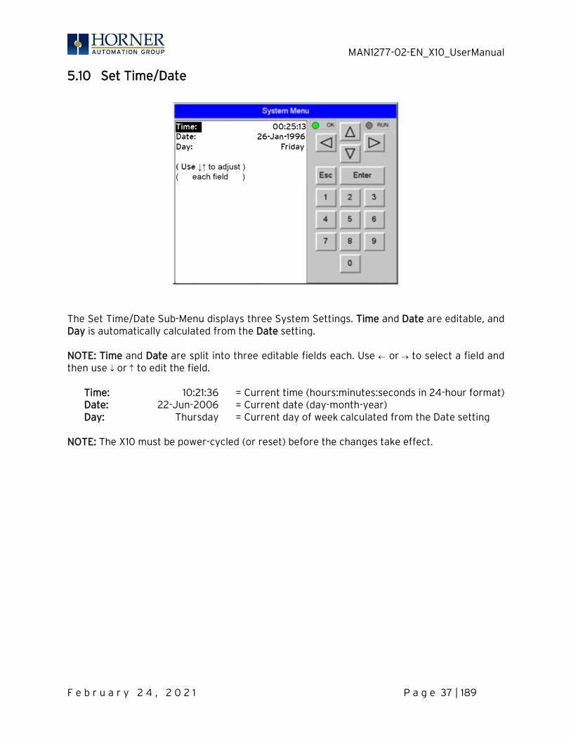
5.10 Set Time/Date
The Set Time/Date Sub-Menu displays three System Settings. Time and Date are editable, and Day is automatically calculated from the Date setting. NOTE: Time and Date are split into three editable fields each. Use or → to select a field and then use or to edit the field.
Time: 10:21:36 = Current time (hours:minutes:seconds in 24-hour format) Date: 22-Jun-2006 = Current date (day-month-year) Day: Thursday = Current day of week calculated from the Date setting
NOTE: The X10 must be power-cycled (or reset) before the changes take effect.
MAN1277-02-EN_X10_UserManual
F e b r u a r y 2 4 , 2 0 2 1 P a g e 38 | 189
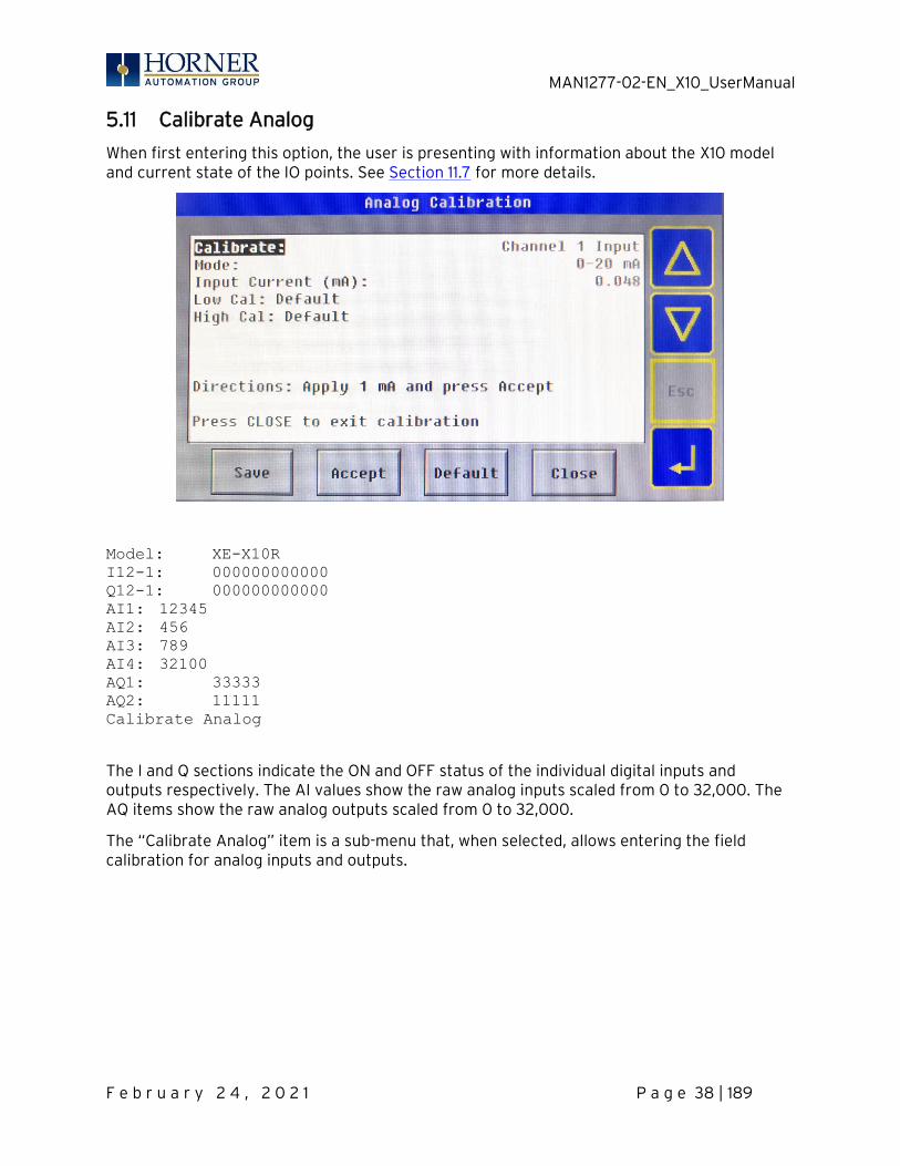
5.11 Calibrate Analog
When first entering this option, the user is presenting with information about the X10 model and current state of the IO points. See Section 11.7 for more details.
Model: XE-X10R
I12-1: 000000000000
Q12-1: 000000000000
AI1: 12345
AI2: 456
AI3: 789
AI4: 32100
AQ1: 33333
AQ2: 11111
Calibrate Analog
The I and Q sections indicate the ON and OFF status of the individual digital inputs and outputs respectively. The AI values show the raw analog inputs scaled from 0 to 32,000. The AQ items show the raw analog outputs scaled from 0 to 32,000.
The “Calibrate Analog” item is a sub-menu that, when selected, allows entering the field calibration for analog inputs and outputs.
MAN1277-02-EN_X10_UserManual
F e b r u a r y 2 4 , 2 0 2 1 P a g e 39 | 189
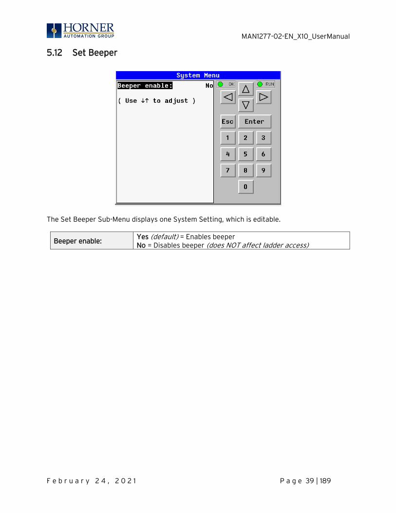
5.12 Set Beeper
The Set Beeper Sub-Menu displays one System Setting, which is editable.
Beeper enable: Yes (default) = Enables beeper No = Disables beeper (does NOT affect ladder access)
MAN1277-02-EN_X10_UserManual
F e b r u a r y 2 4 , 2 0 2 1 P a g e 40 | 189
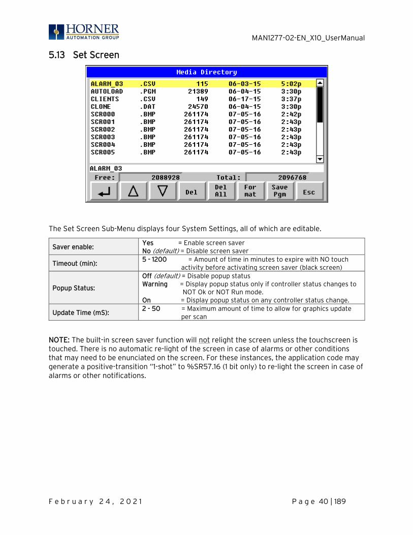
5.13 Set Screen
The Set Screen Sub-Menu displays four System Settings, all of which are editable.
Saver enable: Yes = Enable screen saver No (default) = Disable screen saver
Timeout (min): 5 - 1200 = Amount of time in minutes to expire with NO touch
activity before activating screen saver (black screen)
Popup Status:
Off (default) = Disable popup status Warning = Display popup status only if controller status changes to NOT Ok or NOT Run mode. On = Display popup status on any controller status change.
Update Time (mS): 2 - 50 = Maximum amount of time to allow for graphics update
per scan
NOTE: The built-in screen saver function will not relight the screen unless the touchscreen is touched. There is no automatic re-light of the screen in case of alarms or other conditions that may need to be enunciated on the screen. For these instances, the application code may generate a positive-transition “1-shot” to %SR57.16 (1 bit only) to re-light the screen in case of alarms or other notifications.
MAN1277-02-EN_X10_UserManual
F e b r u a r y 2 4 , 2 0 2 1 P a g e 41 | 189
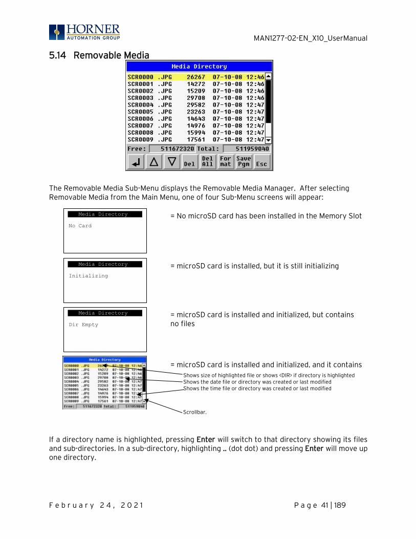
5.14 Removable Media
The Removable Media Sub-Menu displays the Removable Media Manager. After selecting Removable Media from the Main Menu, one of four Sub-Menu screens will appear: If a directory name is highlighted, pressing Enter will switch to that directory showing its files and sub-directories. In a sub-directory, highlighting .. (dot dot) and pressing Enter will move up one directory.
Media Directory
No Card
Media Directory
Dir Empty
Media Directory
Initializing
= No microSD card has been installed in the Memory Slot
= microSD card is installed, but it is still initializing
= microSD card is installed and initialized, but contains no files
Scrollbar.
Shows size of highlighted file or shows <DIR> if directory is highlighted Shows the date file or directory was created or last modified Shows the time file or directory was created or last modified
= microSD card is installed and initialized, and it contains files
MAN1277-02-EN_X10_UserManual
F e b r u a r y 2 4 , 2 0 2 1 P a g e 42 | 189
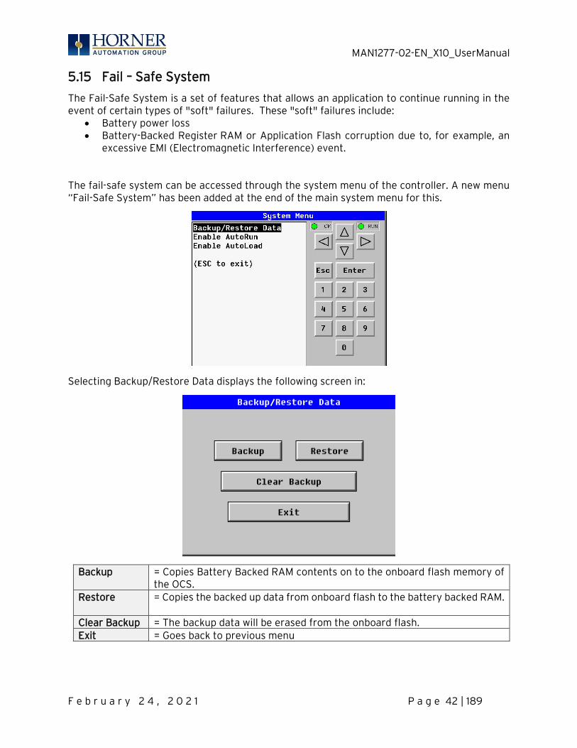
5.15 Fail – Safe System
The Fail-Safe System is a set of features that allows an application to continue running in the event of certain types of "soft" failures. These "soft" failures include:
• Battery power loss • Battery-Backed Register RAM or Application Flash corruption due to, for example, an
excessive EMI (Electromagnetic Interference) event. The fail-safe system can be accessed through the system menu of the controller. A new menu “Fail-Safe System” has been added at the end of the main system menu for this.
Selecting Backup/Restore Data displays the following screen in:
Backup
= Copies Battery Backed RAM contents on to the onboard flash memory of the OCS.
Restore
= Copies the backed up data from onboard flash to the battery backed RAM.
Clear Backup = The backup data will be erased from the onboard flash. Exit = Goes back to previous menu
MAN1277-02-EN_X10_UserManual
F e b r u a r y 2 4 , 2 0 2 1 P a g e 43 | 189
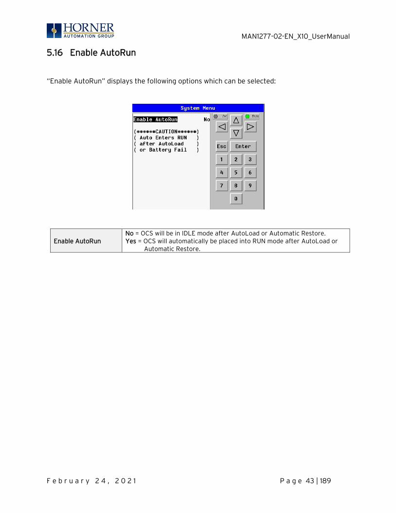
5.16 Enable AutoRun
“Enable AutoRun” displays the following options which can be selected:
Enable AutoRun No = OCS will be in IDLE mode after AutoLoad or Automatic Restore. Yes = OCS will automatically be placed into RUN mode after AutoLoad or Automatic Restore.
MAN1277-02-EN_X10_UserManual
F e b r u a r y 2 4 , 2 0 2 1 P a g e 44 | 189
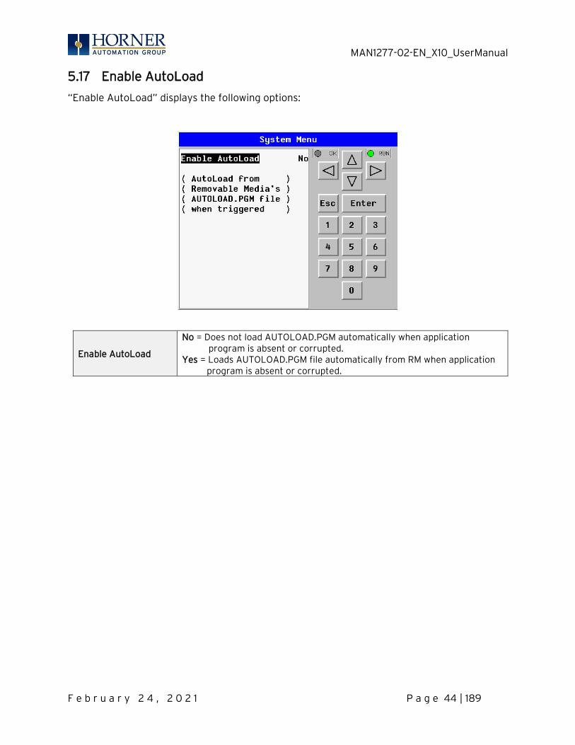
5.17 Enable AutoLoad
“Enable AutoLoad” displays the following options:
Enable AutoLoad
No = Does not load AUTOLOAD.PGM automatically when application program is absent or corrupted.
Yes = Loads AUTOLOAD.PGM file automatically from RM when application program is absent or corrupted.
MAN1277-02-EN_X10_UserManual
F e b r u a r y 2 4 , 2 0 2 1 P a g e 45 | 189
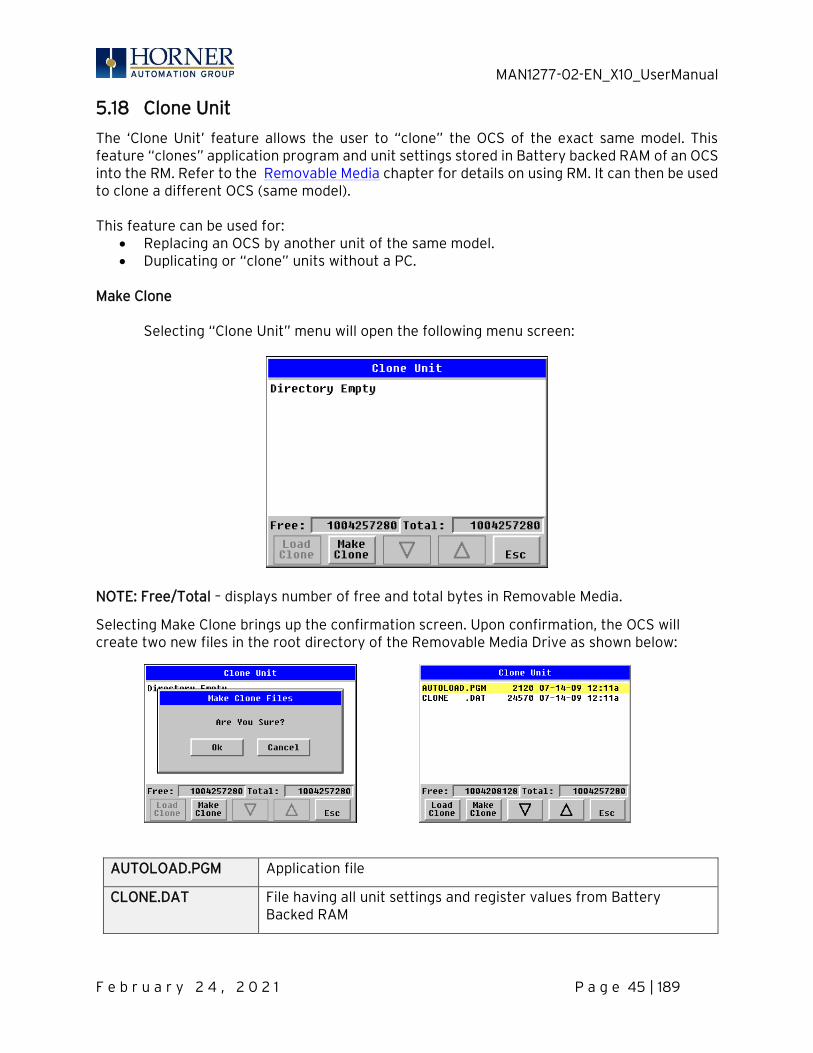
5.18 Clone Unit
The ‘Clone Unit’ feature allows the user to “clone” the OCS of the exact same model. This feature “clones” application program and unit settings stored in Battery backed RAM of an OCS into the RM. Refer to the Removable Media chapter for details on using RM. It can then be used to clone a different OCS (same model). This feature can be used for:
• Replacing an OCS by another unit of the same model. • Duplicating or “clone” units without a PC.
Make Clone Selecting “Clone Unit” menu will open the following menu screen:
NOTE: Free/Total – displays number of free and total bytes in Removable Media.
Selecting Make Clone brings up the confirmation screen. Upon confirmation, the OCS will create two new files in the root directory of the Removable Media Drive as shown below:
AUTOLOAD.PGM Application file
CLONE.DAT File having all unit settings and register values from Battery Backed RAM
MAN1277-02-EN_X10_UserManual
F e b r u a r y 2 4 , 2 0 2 1 P a g e 46 | 189
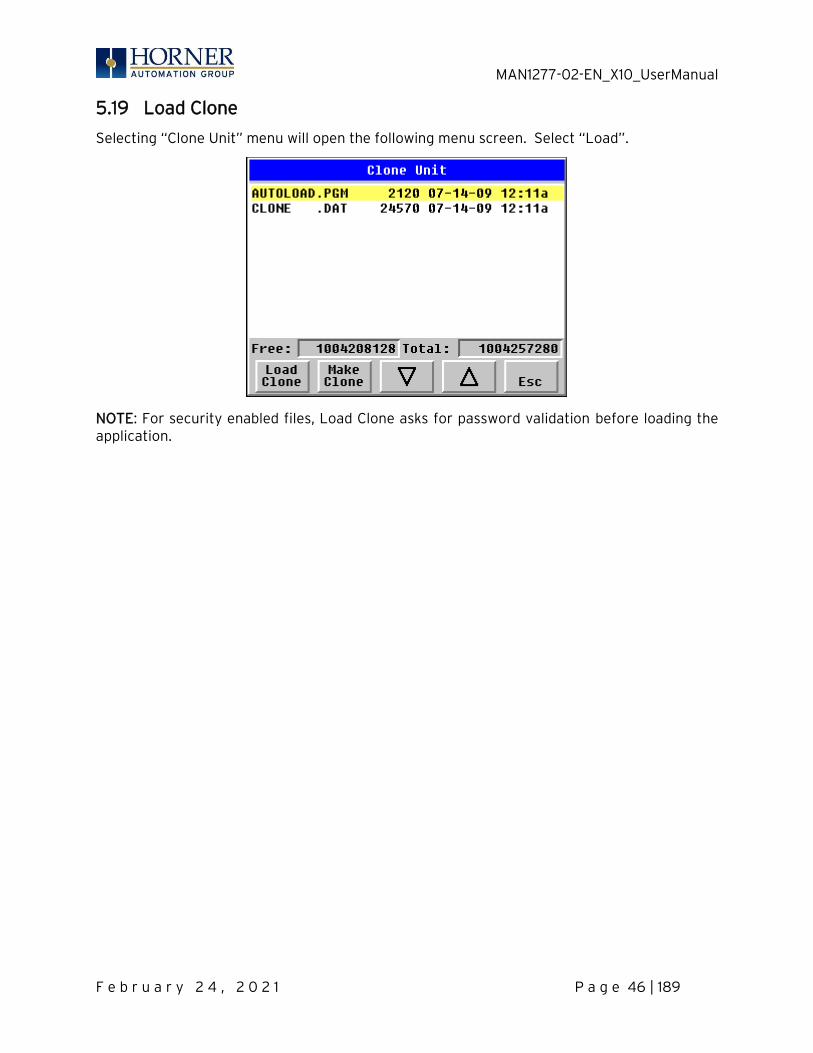
5.19 Load Clone
Selecting “Clone Unit” menu will open the following menu screen. Select “Load”.
NOTE: For security enabled files, Load Clone asks for password validation before loading the application.
MAN1277-02-EN_X10_UserManual
F e b r u a r y 2 4 , 2 0 2 1 P a g e 47 | 189
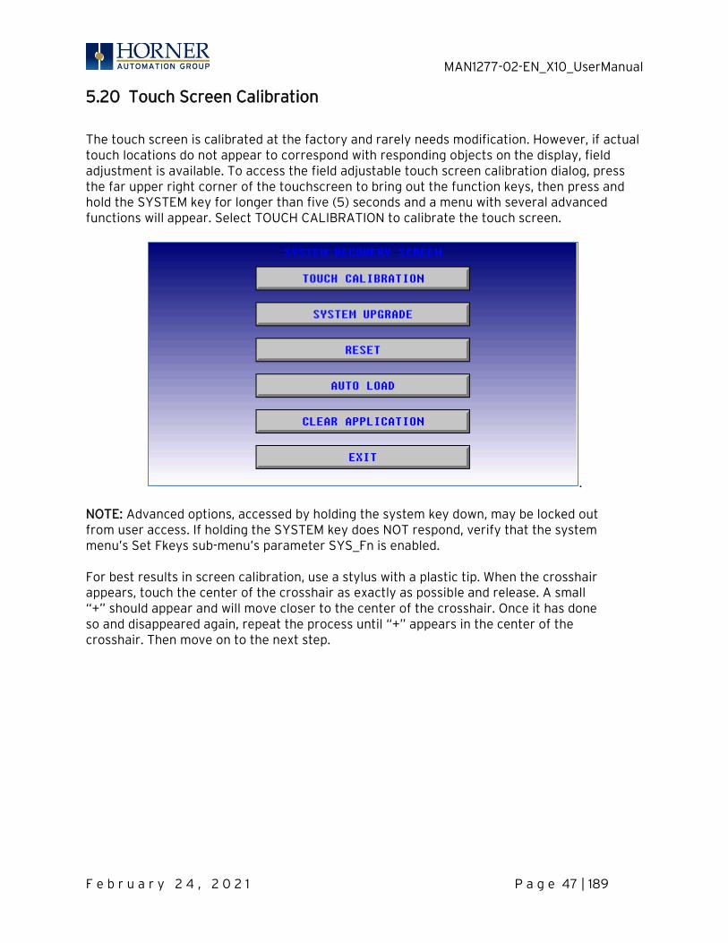
5.20 Touch Screen Calibration
The touch screen is calibrated at the factory and rarely needs modification. However, if actual touch locations do not appear to correspond with responding objects on the display, field adjustment is available. To access the field adjustable touch screen calibration dialog, press the far upper right corner of the touchscreen to bring out the function keys, then press and hold the SYSTEM key for longer than five (5) seconds and a menu with several advanced functions will appear. Select TOUCH CALIBRATION to calibrate the touch screen.
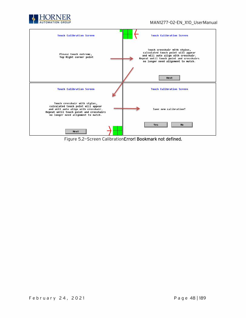
. NOTE: Advanced options, accessed by holding the system key down, may be locked out from user access. If holding the SYSTEM key does NOT respond, verify that the system menu’s Set Fkeys sub-menu’s parameter SYS_Fn is enabled. For best results in screen calibration, use a stylus with a plastic tip. When the crosshair appears, touch the center of the crosshair as exactly as possible and release. A small “+” should appear and will move closer to the center of the crosshair. Once it has done so and disappeared again, repeat the process until “+” appears in the center of the crosshair. Then move on to the next step.
MAN1277-02-EN_X10_UserManual
F e b r u a r y 2 4 , 2 0 2 1 P a g e 48 | 189
Figure 5.2—Screen CalibrationError! Bookmark not defined.

MAN1277-02-EN_X10_UserManual
F e b r u a r y 2 4 , 2 0 2 1 P a g e 49 | 189
CHAPTER 6: REGISTERS
6.1 Register Definitions
When programming the X10 OCS, data is stored in memory that is segmented into different types. This memory in the controller is referred to as registers. Different groups of registers are defined as either bits or words (16 bits). Multiple registers can usually be used to handle larger storage requirements. For example, 16 single-bit registers can be used to store a word, or two 16-bit registers can be used to store a 32-bit value.
Table 6.1 - Types of Registers found in the X10 OCSError! Bookmark not defined.
%I Digital Input Single-bit input registers. Typically, an external switch is connected to the registers.
%Q Digital Output Single-bit output registers. Typically, these bits are connected to an actuator, indicator light or other physical outputs.
%AI Analog Input 16-bit input registers used to gather analog input data such as voltages, temperatures, and speed settings coming from an attached device.
%AQ Analog Output 16-bit output registers used to send analog information such a voltages, levels or speed settings to an attached device.
%M Retentive Bit Retentive single-bit registers. %T Temporary Bit Non-retentive single-bit registers. %R General Purpose Register
Retentive 16-bit registers.
%D Display Bit These are digital flags used to control the displaying of screens on a unit which can display a screen. If the bit is SET, the screen is displayed.
%K Key Bit Single-bit flags used to give the programmer direct access to any front panel keys appearing on a unit.
%S System Bit Single-bit bit coils predefined for system use. %SR System Register 16-bit registers predefined for system use.
6.2 Useful %S and %SR registers
Table 6.2 – Common %S Register DefinitionsError! Bookmark not defined. Register Name Description
%S1 FST_SCN Indicate First Scan %S2 NET_OK Network is OK %S3 T_10MS 10mS timebase %S4 T_100MS 100mS timebase %S5 T_1SEC 1 second timebase %S6 IO_OK I/O is OK %S7 ALW_ON Always ON %S8 ALW_OFF Always OFF %S9 PAUSING_SCN Pause 'n Load soon %S10 RESUMED_SCN Pause 'n load done %S11 FORCE I/O being forced %S12 FORCE_EN Forcing is enabled %S13 NET_IO_OK Network I/O is OK

MAN1277-02-EN_X10_UserManual
F e b r u a r y 2 4 , 2 0 2 1 P a g e 50 | 189
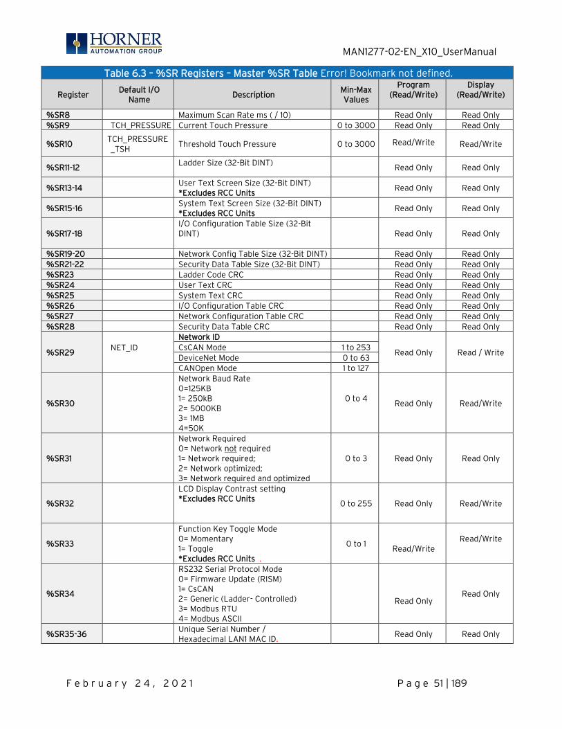
Table 6.3 – %SR Registers – Master %SR Table Error! Bookmark not defined.
Register Default I/O
Name Description
Min-Max Values
Program (Read/Write)
Display (Read/Write)
%SR1 USER_SCR User Screen Number *Excludes RCC Units
0 to 1023 Read/Write Read/Write
%SR2 ALRM_SCR Alarm Screen Number (0=none) *Excludes RCC Units
0 to 1023 Read Only Read Only
%SR3 SYS_SCR
System Screen Number 1 = Main System Menu 2= Set Network ID, Network Status, (%SR29) 3= Set Network Baud (%SR30) 4= Set Contrast (%SR32) 5= View OCS Status 6= View OCS Diagnostics 7= View I/O Slots 8= Set Function Key Mode (%SR33) 9= Set Serial Ports (%SR34) 10= Set Time/Date (%SR44-%SR50) 11= Set Beeper (%SR183) 12= Set Screen (%SR185) 13= Removable Media 14= View Protocols 15= IP Address (ETN I/O Board) 16= Fail Safe System 17= Backup / Restore Data 18= Enable AutoRun 19= Enable AutoLoad 20= Clone Unit - 21= Touch Calibration 24= License Details *Excludes RCC Units.
0 to 24
Read/Write Read/Write
%SR4 SELF_TST Self-Test Results Read Only Read Only %SR4.1 Self-Test Results – BIOS Error Read Only Read Only %SR4.2 Self-Test Results – Engine Error Read Only Read Only %SR4.3 Self-Test Results – Ladder Error Read Only Read Only %SR4.4 Self-Test Results – RAM Error Read Only Read Only %SR4.5 Self-Test Results – Duplicate ID Error Read Only Read Only %SR4.6 Self-Test Results – Bad ID Error Read Only Read Only
%SR4.7 Self-Test Results – I/O Configuration
Error Read Only Read Only
%SR4.8 Self-Test Results – Bad Network Error Read Only Read Only %SR4.9 Self-Test Results – Bad Logic Error Read Only Read Only %SR4.10 Self-Test Results – Bad Clock Error Read Only Read Only %SR4.11 Self-Test Results – DeviceNet Error Read Only Read Only
%SR4.12-.16 Reserved
%SR5 CS_MODE
Control Station Mode 0= Idle 1= Do I/O 2= Run 3= Online Change *Controller specific
0 to 3
Read Only Read/Write
%SR6 Average Scan Rate ms ( / 10) Read Only Read Only %SR7 Minimum Scan Rate ms ( / 10) Read Only Read Only
MAN1277-02-EN_X10_UserManual
F e b r u a r y 2 4 , 2 0 2 1 P a g e 51 | 189
Table 6.3 – %SR Registers – Master %SR Table Error! Bookmark not defined.
Register Default I/O
Name Description
Min-Max Values
Program (Read/Write)
Display (Read/Write)
%SR8 Maximum Scan Rate ms ( / 10) Read Only Read Only %SR9 TCH_PRESSURE Current Touch Pressure 0 to 3000 Read Only Read Only
%SR10 TCH_PRESSURE_TSH
Threshold Touch Pressure 0 to 3000
Read/Write
Read/Write
%SR11-12 Ladder Size (32-Bit DINT)
Read Only Read Only
%SR13-14 User Text Screen Size (32-Bit DINT) *Excludes RCC Units
Read Only Read Only
%SR15-16 System Text Screen Size (32-Bit DINT) *Excludes RCC Units
Read Only Read Only
%SR17-18 I/O Configuration Table Size (32-Bit DINT)
Read Only Read Only
%SR19-20 Network Config Table Size (32-Bit DINT) Read Only Read Only %SR21-22 Security Data Table Size (32-Bit DINT) Read Only Read Only %SR23 Ladder Code CRC Read Only Read Only %SR24 User Text CRC Read Only Read Only %SR25 System Text CRC Read Only Read Only %SR26 I/O Configuration Table CRC Read Only Read Only %SR27 Network Configuration Table CRC Read Only Read Only %SR28 Security Data Table CRC Read Only Read Only
%SR29 NET_ID
Network ID
Read Only Read / Write CsCAN Mode 1 to 253 DeviceNet Mode 0 to 63 CANOpen Mode 1 to 127
%SR30
Network Baud Rate 0=125KB 1= 250kB 2= 5000KB 3= 1MB 4=50K
0 to 4
Read Only Read/Write
%SR31
Network Required 0= Network not required 1= Network required; 2= Network optimized; 3= Network required and optimized
0 to 3 Read Only Read Only
%SR32
LCD Display Contrast setting *Excludes RCC Units
0 to 255 Read Only Read/Write
%SR33
Function Key Toggle Mode 0= Momentary 1= Toggle *Excludes RCC Units .
0 to 1
Read/Write Read/Write
%SR34
RS232 Serial Protocol Mode 0= Firmware Update (RISM) 1= CsCAN 2= Generic (Ladder- Controlled) 3= Modbus RTU 4= Modbus ASCII
Read Only
Read Only
%SR35-36 Unique Serial Number / Hexadecimal LAN1 MAC ID. Read Only Read Only
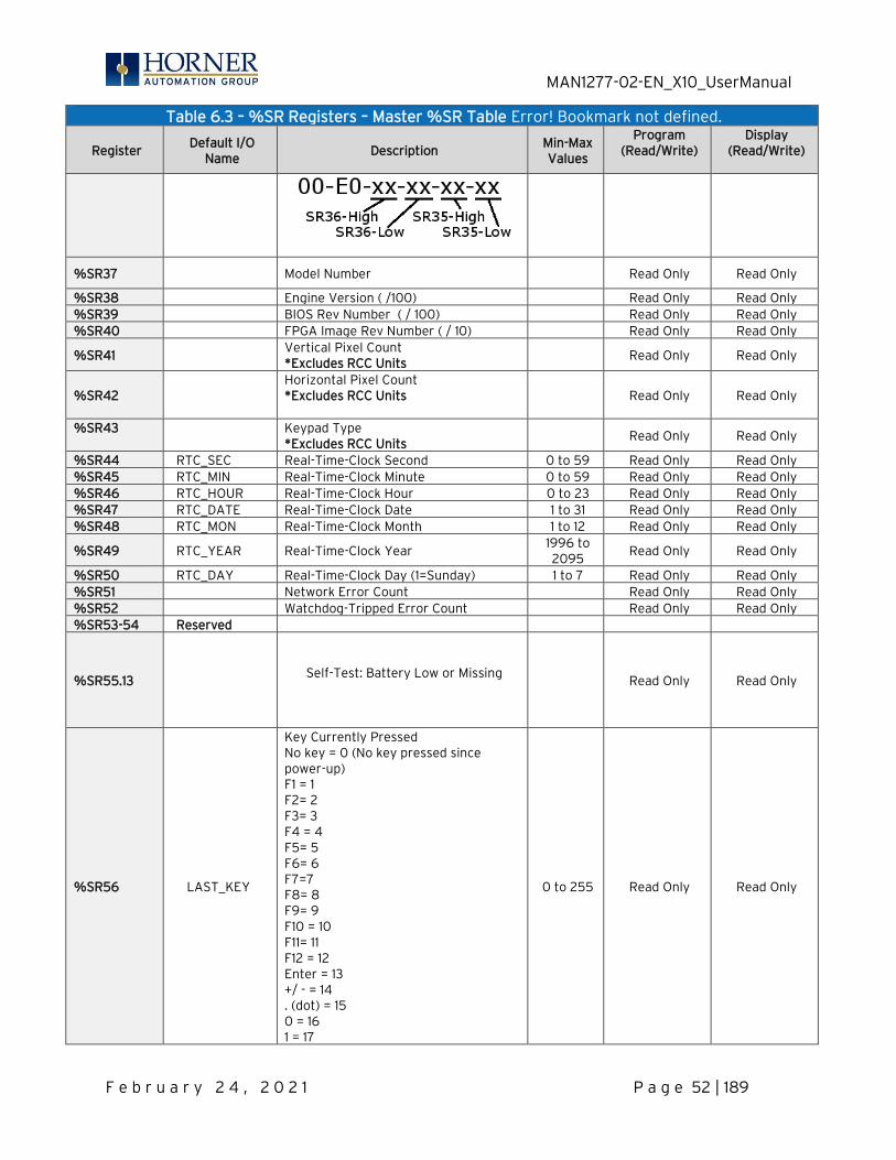
MAN1277-02-EN_X10_UserManual
F e b r u a r y 2 4 , 2 0 2 1 P a g e 52 | 189
Table 6.3 – %SR Registers – Master %SR Table Error! Bookmark not defined.
Register Default I/O
Name Description
Min-Max Values
Program (Read/Write)
Display (Read/Write)
%SR37 Model Number Read Only Read Only
%SR38 Engine Version ( /100) Read Only Read Only %SR39 BIOS Rev Number ( / 100) Read Only Read Only %SR40 FPGA Image Rev Number ( / 10) Read Only Read Only
%SR41 Vertical Pixel Count *Excludes RCC Units
Read Only Read Only
%SR42 Horizontal Pixel Count *Excludes RCC Units
Read Only Read Only
%SR43 Keypad Type *Excludes RCC Units
Read Only Read Only
%SR44 RTC_SEC Real-Time-Clock Second 0 to 59 Read Only Read Only %SR45 RTC_MIN Real-Time-Clock Minute 0 to 59 Read Only Read Only %SR46 RTC_HOUR Real-Time-Clock Hour 0 to 23 Read Only Read Only %SR47 RTC_DATE Real-Time-Clock Date 1 to 31 Read Only Read Only %SR48 RTC_MON Real-Time-Clock Month 1 to 12 Read Only Read Only
%SR49 RTC_YEAR Real-Time-Clock Year 1996 to 2095
Read Only Read Only
%SR50 RTC_DAY Real-Time-Clock Day (1=Sunday) 1 to 7 Read Only Read Only %SR51 Network Error Count Read Only Read Only %SR52 Watchdog-Tripped Error Count Read Only Read Only %SR53-54 Reserved
%SR55.13
Self-Test: Battery Low or Missing
Read Only Read Only
%SR56 LAST_KEY
Key Currently Pressed No key = 0 (No key pressed since power-up) F1 = 1 F2= 2 F3= 3 F4 = 4 F5= 5 F6= 6 F7=7 F8= 8 F9= 9 F10 = 10 F11= 11 F12 = 12 Enter = 13 +/ - = 14 . (dot) = 15 0 = 16 1 = 17
0 to 255
Read Only
Read Only

MAN1277-02-EN_X10_UserManual
F e b r u a r y 2 4 , 2 0 2 1 P a g e 53 | 189
Table 6.3 – %SR Registers – Master %SR Table Error! Bookmark not defined.
Register Default I/O
Name Description
Min-Max Values
Program (Read/Write)
Display (Read/Write)
2 = 18 3 = 19 4 = 20 5 = 21 6 = 22 7= 23 8 = 24 9 = 25 System = 26 Escape = 27 Left = 28 Right = 29 Up = 30 Down = 31 Shift = 32 Soft Key 1 = 34 Soft Key 2 = 35 Soft Key 3 = 36 Soft Key 4 = 37 Soft Key 5 = 38 Soft Key 6 = 39 Soft Key 7 = 40 Soft Key 8 = 41 Release = 255 (Keys pressed since power-up but not currently) *Excludes RCC Units
%SR57
LCD Backlight Dimmer Register 0-100 = 0% to 100% On 100-255 = 100% On *Excludes RCC Units
0 to 255 Read/Write Read/Write
%57.16 Temporarily disable Screen Saver *Excludes RCC Units
Read/Write Read/Write
%SR58 USER_LEDS
User LEDs Read/Write Read/Write
%SR59 Engine Build Number (Only last three numbers displayed)
Read Only Read Only
%SR60
Build Option Build Test = 0 Build Beta = 1 Build Product = 2
0 to 2
Read Only
Read Only
%SR61 NUM_IDS Number of CsCAN Network IDs Read Only Read Only
%SR62-100 Reserved
%SR101.3 WebMI License Details – WebMI server status *XLEe, XLTe, X2, X4, & X10 only
Read Only Read Only
%SR101.4 WebMI License Details – WebMI user logged in status *XLEe, XLTe, X2, X4, & X10 only
Read Only Read Only
%SR101.8-101.16
WebMI License Details – Number of users *XLEe, XLTe, X2, X4, & X10 only
Read Only Read Only
%SR102-107 Reserved
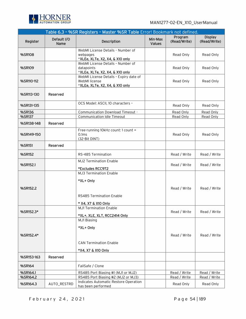
MAN1277-02-EN_X10_UserManual
F e b r u a r y 2 4 , 2 0 2 1 P a g e 54 | 189
Table 6.3 – %SR Registers – Master %SR Table Error! Bookmark not defined.
Register Default I/O
Name Description
Min-Max Values
Program (Read/Write)
Display (Read/Write)
%SR108 WebMI License Details – Number of webpages *XLEe, XLTe, X2, X4, & X10 only
Read Only Read Only
%SR109 WebMI License Details – Number of datapoints *XLEe, XLTe, X2, X4, & X10 only
Read Only Read Only
%SR110-112 WebMI License Details – Expiry date of WebMI license *XLEe, XLTe, X2, X4, & X10 only
Read Only Read Only
%SR113-130 Reserved
%SR131-135 OCS Model: ASCII, 10 characters –
Read Only Read Only
%SR136 Communication Download Timeout – Read Only Read Only %SR137 Communication Idle Timeout Read Only Read Only
%SR138-148 Reserved
%SR149-150 Free-running 10kHz count: 1 count = 0.1ms (32-Bit DINT)
Read Only Read Only
%SR151 Reserved
%SR152 RS-485 Termination Read / Write Read / Write
%SR152.1 MJ2 Termination Enable
*Excludes RCC972 Read / Write Read / Write
%SR152.2
MJ3 Termination Enable
*XL+ Only
RS485 Termination Enable
* X4, X7 & X10 Only
Read / Write Read / Write
%SR152.3* MJ1 Termination Enable
*XL+, XLE, XLT, RCC2414 Only Read / Write Read / Write
%SR152.4*
MJ1 Biasing
*XL+ Only
CAN Termination Enable
*X4, X7 & X10 Only
Read / Write Read / Write
%SR153-163 Reserved
%SR164 FailSafe / Clone
%SR164.1 RS485 Port Biasing #1 (MJ1 or MJ2) Read / Write Read / Write %SR164.2 RS485 Port Biasing #2 (MJ2 or MJ3) Read / Write Read / Write
%SR164.3 AUTO_RESTRD Indicates Automatic Restore Operation has been performed
Read Only Read Only
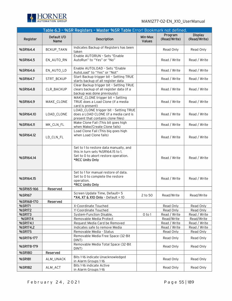
MAN1277-02-EN_X10_UserManual
F e b r u a r y 2 4 , 2 0 2 1 P a g e 55 | 189
Table 6.3 – %SR Registers – Master %SR Table Error! Bookmark not defined.
Register Default I/O
Name Description
Min-Max Values
Program (Read/Write)
Display (Read/Write)
%SR164.4 BCKUP_TAKN Indicates Backup of Registers has been taken
Read Only Read Only
%SR164.5 EN_AUTO_RN Enable AUTORUN – Sets “Enable AutoRun” to “Yes” or “No”
Read / Write Read / Write
%SR164.6 EN_AUTO_LD Enable AUTOLOAD – Sets “Enable AutoLoad” to “Yes” or “Not”
Read / Write Read / Write
%SR164.7 STRT_BCKUP Start Backup trigger bit – Setting TRUE starts backup of all register data
Read / Write Read / Write
%SR164.8 CLR_BACKUP Clear Backup trigger bit – Setting TRUE clears backup of all register data (if a backup was done previously)
Read / Write Read / Write
%SR164.9 MAKE_CLONE MAKE_CLONE trigger bit = Setting TRUE does a Load Clone (if a media card is present)
Read / Write Read / Write
%SR164.10 LOAD_CLONE LOAD_CLONE trigger bit – Setting TRUE does a LOAD CLONE (if a media card is present that contains clone files)
Read / Write Read / Write
%SR164.11 MK_CLN_FL Make Clone Fail (This bit goes high when Make/Create Clone fails)
Read / Write Read / Write
%SR164.12
LD_CLN_FL
Load Clone Fail (This big goes high when Load Clone fails)
Read / Write Read / Write
%SR164.14
Set to 1 to restore data manually, and this in turn sets %SR164.15 to 1. Set to 0 to abort restore operation. *RCC Units Only
Read / Write Read / Write
%SR164.15
Set to 1 for manual restore of data. Set to 0 to complete the restore operation. *RCC Units Only
Read / Write Read / Write
%SR165-166 Reserved
%SR167 Screen Update Time, Default= 5 *X4, X7 & X10 Only – Default = 10
2 to 50 Read/Write Read/Write
%SR168-170 Reserved %SR171 X-Coordinate Touched Read Only Read Only %SR172 Y-Coordinate Touched Read Only Read Only %SR173 System-Function Disable, 0 to 1 Read / Write Read / Write %SR174 Removable Media Protect Read/Write Read/Write %SR174.1 Request Media Card be Removed Read / Write Read / Write %SR174.2 Indicates safe to remove Media Read / Write Read / Write %SR175 Removable Media - Status Read Only Read Only
%SR176-177 Removable Media Free Space (32-Bit DINT)
Read Only Read Only
%SR178-179 Removable Media Total Space (32-Bit DINT)
Read Only Read Only
%SR180 Reserved
%SR181 ALM_UNACK Bits 1-16 indicate Unacknowledged in Alarm Groups 1-16
Read Only Read Only
%SR182 ALM_ACT Bits 1-16 indicate Active in Alarm Groups 1-16
Read Only Read Only
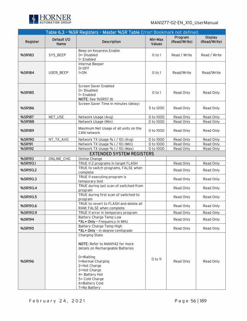
MAN1277-02-EN_X10_UserManual
F e b r u a r y 2 4 , 2 0 2 1 P a g e 56 | 189
Table 6.3 – %SR Registers – Master %SR Table Error! Bookmark not defined.
Register Default I/O
Name Description
Min-Max Values
Program (Read/Write)
Display (Read/Write)
%SR183 SYS_BEEP Beep on Keypress Enable 0= Disabled 1= Enabled
0 to 1 Read / Write Read / Write
%SR184 USER_BEEP
Internal Beeper 0=OFF 1=ON
0 to 1 Read/Write Read/Write
%SR185
Screen Saver Enabled 0= Disabled 1= Enabled NOTE: See %SR57.16
0 to 1 Read Only Read Only
%SR186 Screen Saver Time in minutes (delay)
5 to 1200 Read Only Read Only
%SR187 NET_USE Network Usage (Avg) 0 to 1000 Read Only Read Only %SR188 Network Usage (Min) 0 to 1000 Read Only Read Only
%SR189 Maximum Net Usage of all units on the CAN network
0 to 1000
Read Only
Read Only
%SR190 NT_TX_AVG Network TX Usage % ( / 10) (Avg) 0 to 1000 Read Only Read Only %SR191 Network TX Usage % ( / 10) (Min) 0 to 1000 Read Only Read Only %SR192 Network TX Usage % ( / 10) (Max) 0 to 1000 Read Only Read Only
EXTENDED SYSTEM REGISTERS %SR193 ONLINE_CHG Online Change %SR193.1 TRUE if 2 programs in target FLASH Read Only Read Only
%SR193.2 TRUE to switch programs, FALSE when complete
Read Only Read Only
%SR193.3 TRUE if executing program is temporary test
Read Only Read Only
%SR193.4 TRUE during last scan of switched-from program
Read Only Read Only
%SR193.5 TRUE during first scan of switched-to program
Read Only Read Only
%SR193.6 TRUE to revert to FLASH and delete all RAM; FALSE when complete
Read Only Read Only
%SR193.9 TRUE if error in temporary program Read Only Read Only
%SR194 Battery Charge Temp Low *XL+ Only – Frequency in MHz
Read Only Read Only
%SR195 Battery Charge Temp High *XL+ Only – in degree centigrade
Read Only Read Only
%SR196
Charging State NOTE: Refer to MAN1142 for more details on Rechargeable Batteries 0=Waiting 1=Normal Charging 2=Hot Charge 3=Hot Charge 4= Battery Hot 5= Cold Charge 6=Battery Cold 7=No Battery
0 to 11
Read Only
Read Only
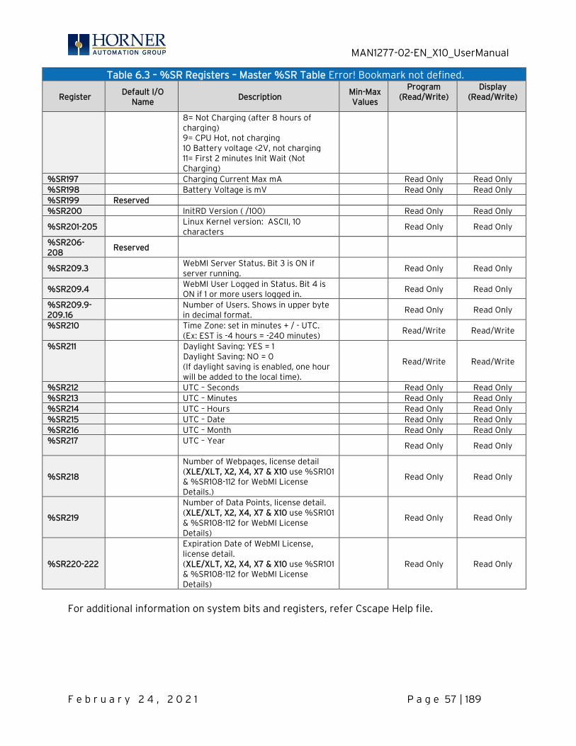
MAN1277-02-EN_X10_UserManual
F e b r u a r y 2 4 , 2 0 2 1 P a g e 57 | 189
Table 6.3 – %SR Registers – Master %SR Table Error! Bookmark not defined.
Register Default I/O
Name Description
Min-Max Values
Program (Read/Write)
Display (Read/Write)
8= Not Charging (after 8 hours of charging) 9= CPU Hot, not charging 10 Battery voltage <2V, not charging 11= First 2 minutes Init Wait (Not Charging)
%SR197 Charging Current Max mA Read Only Read Only %SR198 Battery Voltage is mV Read Only Read Only %SR199 Reserved %SR200 InitRD Version ( /100) Read Only Read Only
%SR201-205 Linux Kernel version: ASCII, 10 characters
Read Only Read Only
%SR206-208
Reserved
%SR209.3 WebMI Server Status. Bit 3 is ON if server running.
Read Only Read Only
%SR209.4 WebMI User Logged in Status. Bit 4 is ON if 1 or more users logged in.
Read Only Read Only
%SR209.9-209.16
Number of Users. Shows in upper byte in decimal format.
Read Only Read Only
%SR210
Time Zone: set in minutes + / - UTC. (Ex: EST is -4 hours = -240 minutes)
Read/Write Read/Write
%SR211
Daylight Saving: YES = 1 Daylight Saving: NO = 0 (If daylight saving is enabled, one hour will be added to the local time).
Read/Write Read/Write
%SR212 UTC – Seconds Read Only Read Only %SR213 UTC – Minutes Read Only Read Only %SR214 UTC – Hours Read Only Read Only %SR215 UTC – Date Read Only Read Only %SR216 UTC – Month Read Only Read Only %SR217
UTC – Year
Read Only Read Only
%SR218
Number of Webpages, license detail (XLE/XLT, X2, X4, X7 & X10 use %SR101 & %SR108-112 for WebMI License Details.)
Read Only Read Only
%SR219
Number of Data Points, license detail. (XLE/XLT, X2, X4, X7 & X10 use %SR101 & %SR108-112 for WebMI License Details)
Read Only Read Only
%SR220-222
Expiration Date of WebMI License, license detail. (XLE/XLT, X2, X4, X7 & X10 use %SR101 & %SR108-112 for WebMI License Details)
Read Only Read Only
For additional information on system bits and registers, refer Cscape Help file.
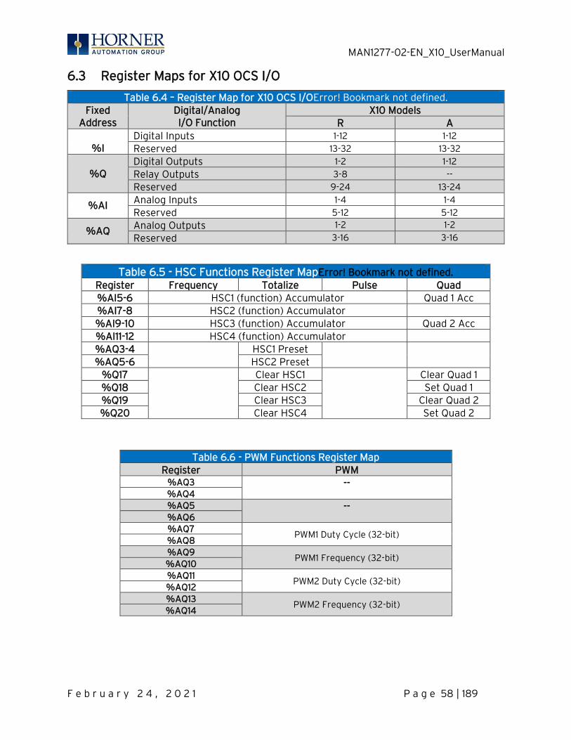
MAN1277-02-EN_X10_UserManual
F e b r u a r y 2 4 , 2 0 2 1 P a g e 58 | 189
6.3 Register Maps for X10 OCS I/O
Table 6.4 – Register Map for X10 OCS I/OError! Bookmark not defined. Fixed
Address Digital/Analog I/O Function
X10 Models R A
%I
Digital Inputs 1-12 1-12
Reserved 13-32 13-32
%Q
Digital Outputs 1-2 1-12
Relay Outputs 3-8 --
Reserved 9-24 13-24
%AI Analog Inputs 1-4 1-4
Reserved 5-12 5-12
%AQ Analog Outputs 1-2 1-2
Reserved 3-16 3-16
Table 6.5 - HSC Functions Register MapError! Bookmark not defined. Register Frequency Totalize Pulse Quad %AI5-6 HSC1 (function) Accumulator Quad 1 Acc %AI7-8 HSC2 (function) Accumulator %AI9-10 HSC3 (function) Accumulator Quad 2 Acc %AI11-12 HSC4 (function) Accumulator %AQ3-4
HSC1 Preset
%AQ5-6 HSC2 Preset
%Q17
Clear HSC1
Clear Quad 1 %Q18 Clear HSC2 Set Quad 1 %Q19 Clear HSC3 Clear Quad 2 %Q20 Clear HSC4 Set Quad 2
Table 6.6 - PWM Functions Register Map Register PWM
%AQ3 -- %AQ4 %AQ5 -- %AQ6 %AQ7
PWM1 Duty Cycle (32-bit) %AQ8 %AQ9
PWM1 Frequency (32-bit) %AQ10 %AQ11
PWM2 Duty Cycle (32-bit) %AQ12 %AQ13
PWM2 Frequency (32-bit) %AQ14
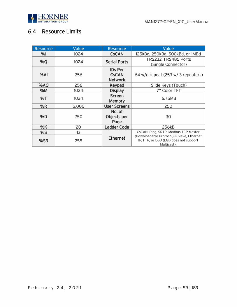
MAN1277-02-EN_X10_UserManual
F e b r u a r y 2 4 , 2 0 2 1 P a g e 59 | 189
6.4 Resource Limits
Resource Value Resource Value %I 1024 CsCAN 125kBd, 250kBd, 500kBd, or 1MBd
%Q 1024 Serial Ports 1 RS232, 1 RS485 Ports
(Single Connector)
%AI 256 IDs Per CsCAN
Network 64 w/o repeat (253 w/ 3 repeaters)
%AQ 256 Keypad Slide Keys (Touch) %M 1024 Display 7” Color TFT
%T 1024 Screen
Memory 6.75MB
%R 5,000 User Screens 250
%D 250 No. of
Objects per Page
30
%K 20 Ladder Code 256kB %S 13
Ethernet
CsCAN, Ping, SRTP, Modbus TCP Master (Downloadable Protocol) & Slave, Ethernet
IP, FTP, or EGD (EGD does not support Multicast).
%SR 255
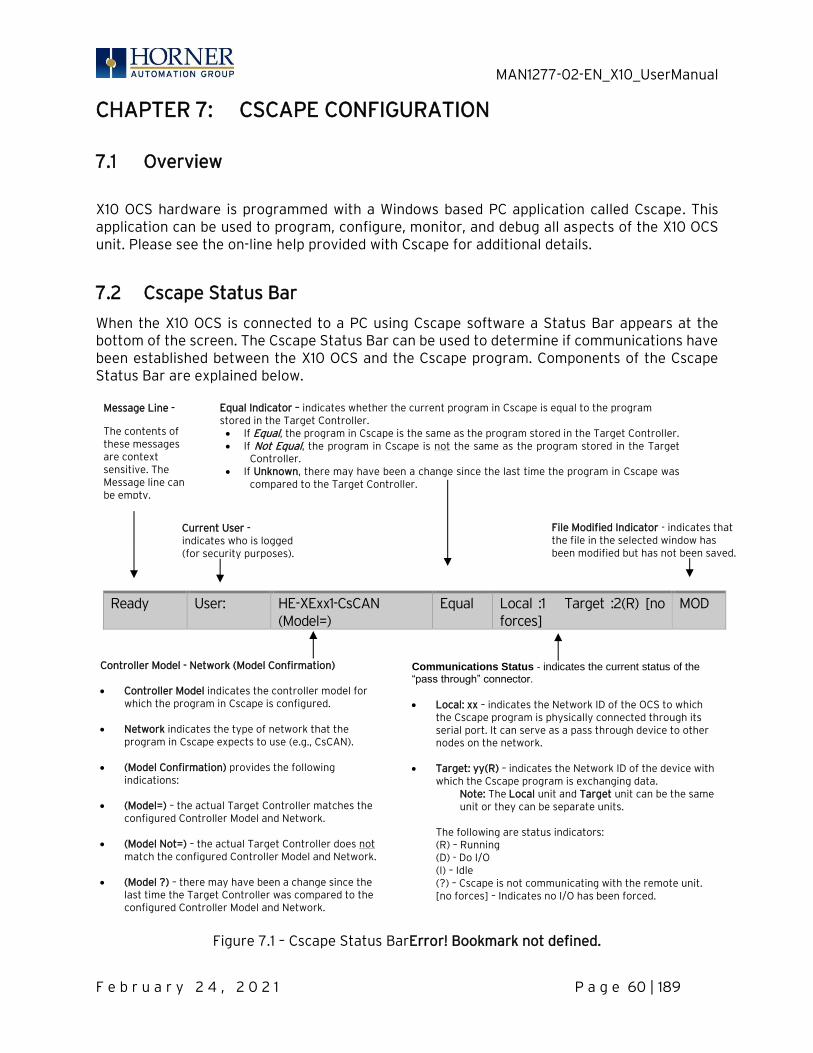
MAN1277-02-EN_X10_UserManual
F e b r u a r y 2 4 , 2 0 2 1 P a g e 60 | 189
CHAPTER 7: CSCAPE CONFIGURATION
7.1 Overview
X10 OCS hardware is programmed with a Windows based PC application called Cscape. This application can be used to program, configure, monitor, and debug all aspects of the X10 OCS unit. Please see the on-line help provided with Cscape for additional details.
7.2 Cscape Status Bar
When the X10 OCS is connected to a PC using Cscape software a Status Bar appears at the bottom of the screen. The Cscape Status Bar can be used to determine if communications have been established between the X10 OCS and the Cscape program. Components of the Cscape Status Bar are explained below.
Ready User: HE-XExx1-CsCAN (Model=)
Equal Local :1 Target :2(R) [no forces]
MOD
Figure 7.1 – Cscape Status BarError! Bookmark not defined.
Equal Indicator – indicates whether the current program in Cscape is equal to the program stored in the Target Controller. • If Equal, the program in Cscape is the same as the program stored in the Target Controller. • If Not Equal, the program in Cscape is not the same as the program stored in the Target
Controller. • If Unknown, there may have been a change since the last time the program in Cscape was
compared to the Target Controller.
Communications Status - indicates the current status of the “pass through” connector.
• Local: xx – indicates the Network ID of the OCS to which
the Cscape program is physically connected through its serial port. It can serve as a pass through device to other nodes on the network.
• Target: yy(R) – indicates the Network ID of the device with
which the Cscape program is exchanging data. Note: The Local unit and Target unit can be the same unit or they can be separate units.
The following are status indicators: (R) – Running (D) - Do I/O (I) – Idle (?) – Cscape is not communicating with the remote unit. [no forces] – Indicates no I/O has been forced.
Message Line -
The contents of these messages are context sensitive. The Message line can be empty.
Current User - indicates who is logged (for security purposes).
Controller Model - Network (Model Confirmation) • Controller Model indicates the controller model for
which the program in Cscape is configured. • Network indicates the type of network that the
program in Cscape expects to use (e.g., CsCAN). • (Model Confirmation) provides the following
indications: • (Model=) – the actual Target Controller matches the
configured Controller Model and Network. • (Model Not=) – the actual Target Controller does not
match the configured Controller Model and Network. • (Model ?) – there may have been a change since the
last time the Target Controller was compared to the configured Controller Model and Network.
File Modified Indicator - indicates that the file in the selected window has been modified but has not been saved.
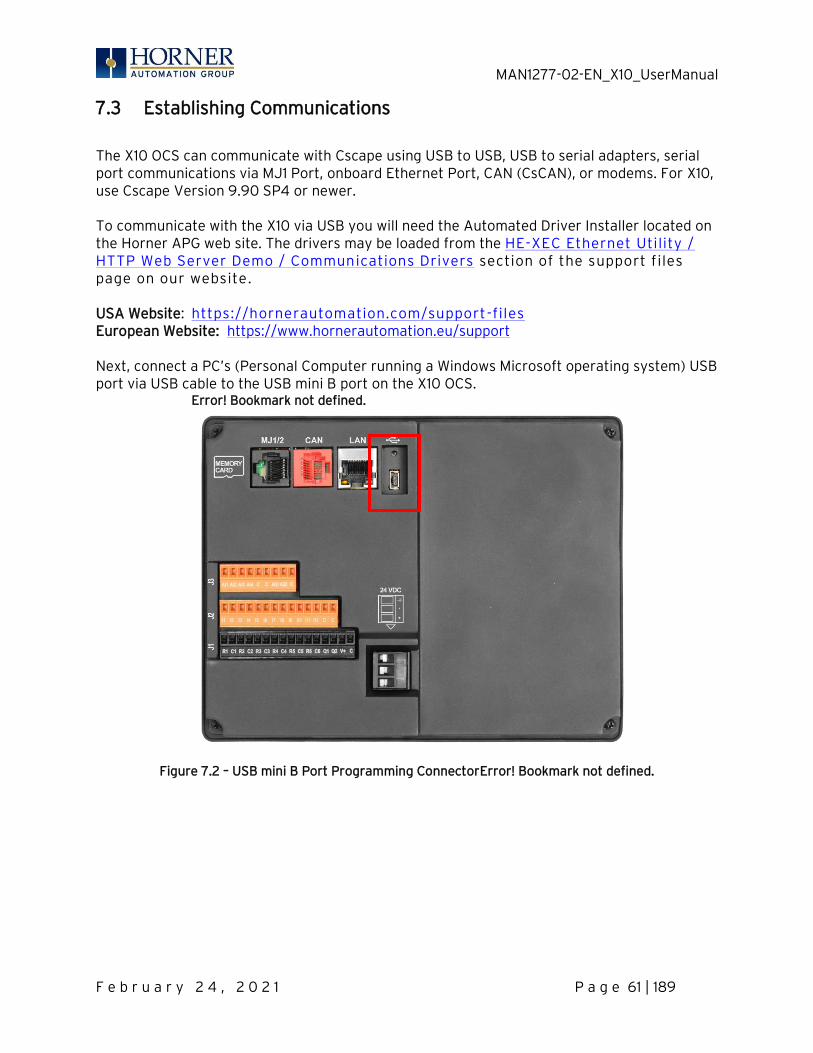
MAN1277-02-EN_X10_UserManual
F e b r u a r y 2 4 , 2 0 2 1 P a g e 61 | 189
7.3 Establishing Communications
The X10 OCS can communicate with Cscape using USB to USB, USB to serial adapters, serial port communications via MJ1 Port, onboard Ethernet Port, CAN (CsCAN), or modems. For X10, use Cscape Version 9.90 SP4 or newer. To communicate with the X10 via USB you will need the Automated Driver Installer located on the Horner APG web site. The drivers may be loaded from the HE-XEC Ethernet Utility / HTTP Web Server Demo / Communications Drivers section of the support files page on our website. USA Website: https://hornerautomation.com/support-files European Website: https://www.hornerautomation.eu/support Next, connect a PC’s (Personal Computer running a Windows Microsoft operating system) USB port via USB cable to the USB mini B port on the X10 OCS. Error! Bookmark not defined.
Figure 7.2 – USB mini B Port Programming ConnectorError! Bookmark not defined.
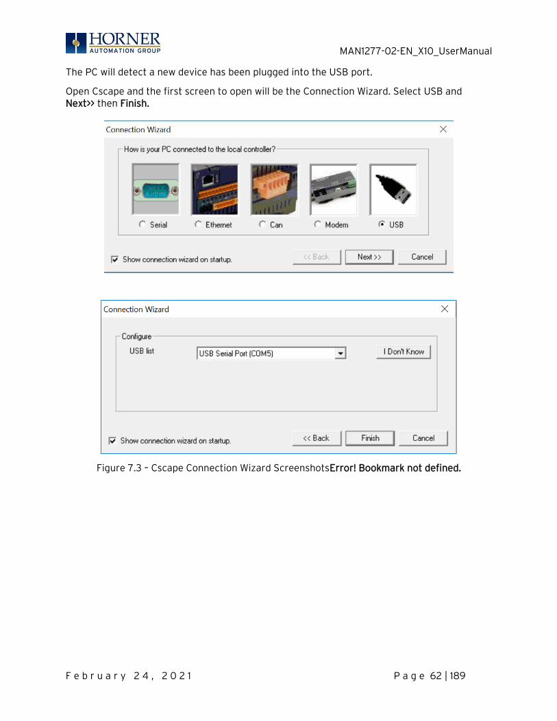
MAN1277-02-EN_X10_UserManual
F e b r u a r y 2 4 , 2 0 2 1 P a g e 62 | 189
The PC will detect a new device has been plugged into the USB port.
Open Cscape and the first screen to open will be the Connection Wizard. Select USB and Next>> then Finish.
Figure 7.3 – Cscape Connection Wizard ScreenshotsError! Bookmark not defined.
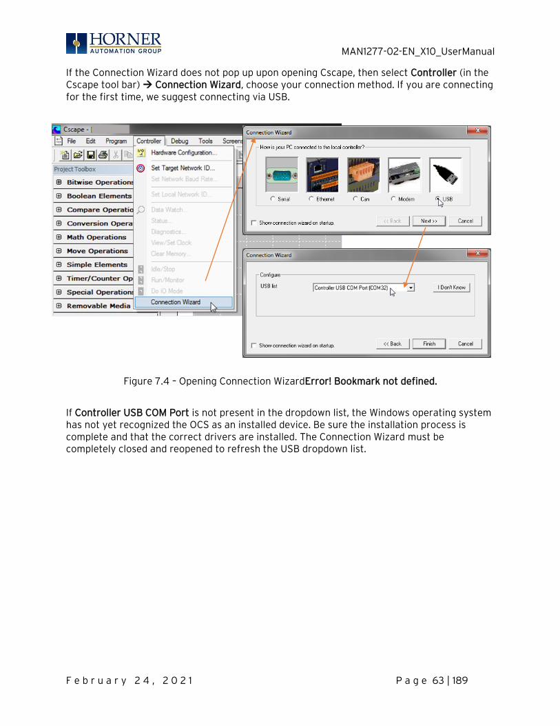
MAN1277-02-EN_X10_UserManual
F e b r u a r y 2 4 , 2 0 2 1 P a g e 63 | 189
If the Connection Wizard does not pop up upon opening Cscape, then select Controller (in the Cscape tool bar) → Connection Wizard, choose your connection method. If you are connecting for the first time, we suggest connecting via USB.
Figure 7.4 – Opening Connection WizardError! Bookmark not defined.
If Controller USB COM Port is not present in the dropdown list, the Windows operating system has not yet recognized the OCS as an installed device. Be sure the installation process is complete and that the correct drivers are installed. The Connection Wizard must be completely closed and reopened to refresh the USB dropdown list.
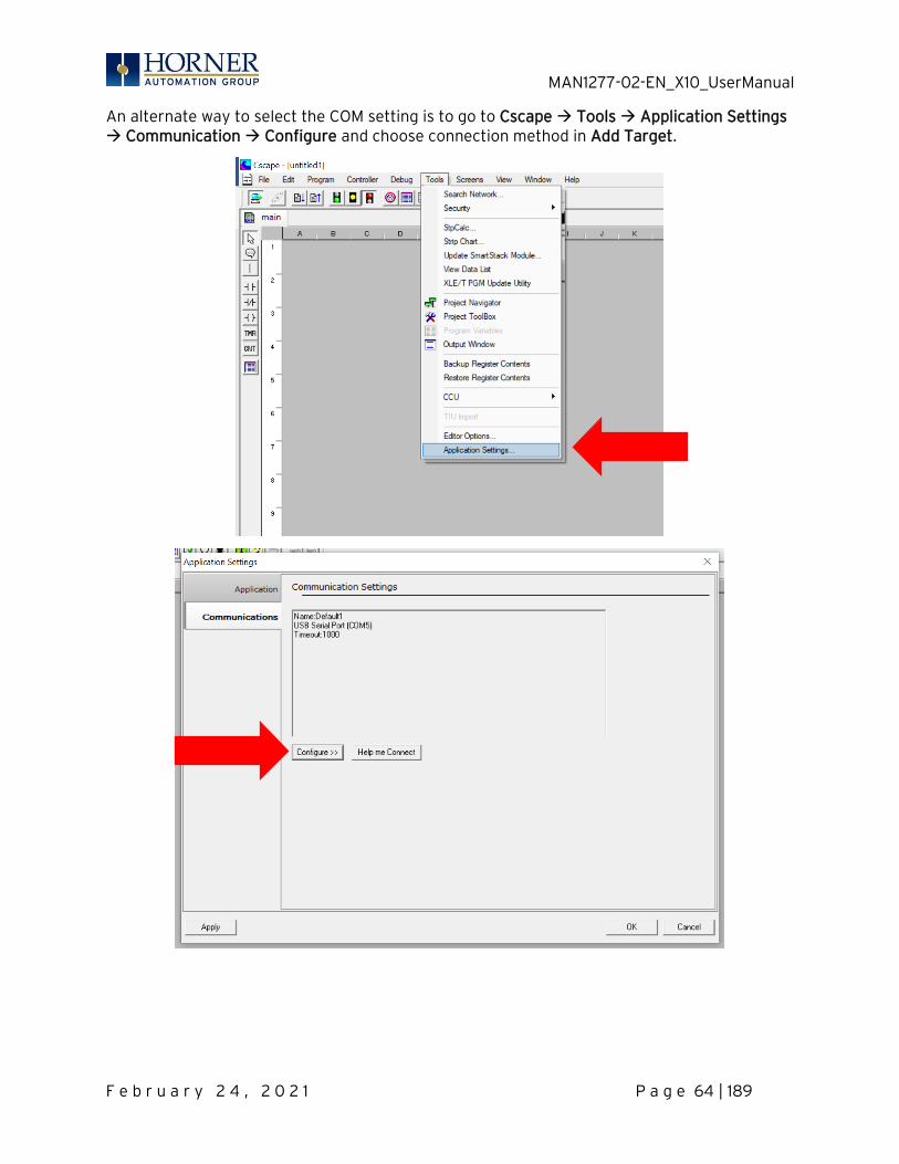
MAN1277-02-EN_X10_UserManual
F e b r u a r y 2 4 , 2 0 2 1 P a g e 64 | 189
An alternate way to select the COM setting is to go to Cscape → Tools → Application Settings → Communication → Configure and choose connection method in Add Target.
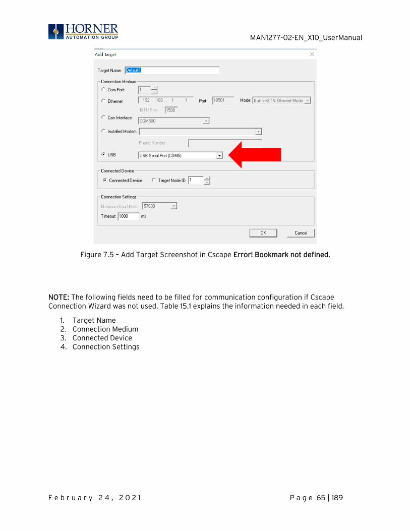
MAN1277-02-EN_X10_UserManual
F e b r u a r y 2 4 , 2 0 2 1 P a g e 65 | 189
Figure 7.5 – Add Target Screenshot in Cscape Error! Bookmark not defined.
NOTE: The following fields need to be filled for communication configuration if Cscape Connection Wizard was not used. Table 15.1 explains the information needed in each field.
1. Target Name 2. Connection Medium 3. Connected Device 4. Connection Settings
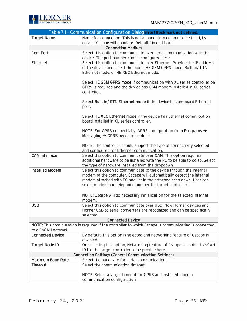
MAN1277-02-EN_X10_UserManual
F e b r u a r y 2 4 , 2 0 2 1 P a g e 66 | 189
Table 7.1 – Communication Configuration DialogError! Bookmark not defined. Target Name Name for connection. This is not a mandatory column to be filled, by
default Cscape will populate ‘Default1’ in edit box. Connection Medium
Com Port Select this option to communicate over serial communication with the device. The port number can be configured here.
Ethernet Select this option to communicate over Ethernet. Provide the IP address of the device and select the mode: HE GSM GPRS mode, Built in/ ETN Ethernet mode, or HE XEC Ethernet mode. Select HE GSM GPRS mode if communication with XL series controller on GPRS is required and the device has GSM modem installed in XL series controller.
Select Built in/ ETN Ethernet mode if the device has on-board Ethernet port. Select HE XEC Ethernet mode if the device has Ethernet comm. option board installed in XL series controller.
NOTE: For GPRS connectivity, GPRS configuration from Programs → Messaging → GPRS needs to be done. NOTE: The controller should support the type of connectivity selected and configured for Ethernet communication.
CAN Interface Select this option to communicate over CAN. This option requires additional hardware to be installed with the PC to be able to do so. Select the type of hardware installed from the dropdown.
Installed Modem Select this option to communicate to the device through the internal modem of the computer. Cscape will automatically detect the internal modem attached with PC and list in the attached drop down. User can select modem and telephone number for target controller.
NOTE: Cscape will do necessary initialization for the selected internal modem.
USB Select this option to communicate over USB. Now Horner devices and Horner USB to serial converters are recognized and can be specifically selected.
Connected Device NOTE: This configuration is required if the controller to which Cscape is communicating is connected to a CsCAN network. Connected Device By default, this option is selected and networking feature of Cscape is
disabled. Target Node ID On selecting this option, Networking feature of Cscape is enabled. CsCAN
ID for the target controller to be provide here. Connection Settings (General Communication Settings)
Maximum Baud Rate Select the baud rate for serial communication. Timeout Select the communication timeout.
NOTE: Select a larger timeout for GPRS and installed modem communication configuration

MAN1277-02-EN_X10_UserManual
F e b r u a r y 2 4 , 2 0 2 1 P a g e 67 | 189
If communication is established, the target indicator will show the mode of the controller Target: yy(R) as shown in the status section above in this chapter, section Cscape Status Bar.
Local ID and Target ID Match
If the controller is not communicating, you may need to set the Target ID of the controller in Cscape or change the controllers ID on the unit itself. The Target ID allows directing communications to a unit when multiple units are connected via a CsCAN network. Units without CsCAN network ports respond to any network ID and do not require the ID to be configured. The main method for communicating between Cscape and an X10 is RS-232 serial. The X10 can communicate with Cscape using USB to serial adapters, CAN (CsCAN) or modems. For communications other than RS-232 serial please refer to the manual that ships with the adapter hardware being used for programming.
NOTE: The following fields need to be filled for communication configuration if Cscape Connection Wizard was not used. Table 15.1 explains the information needed in each field.
5. Target Name 6. Connection Medium 7. Connected Device 8. Connection Settings
When connected directly to the controller to which Cscape communications are required, the Local ID and the Target ID should match.

MAN1277-02-EN_X10_UserManual
F e b r u a r y 2 4 , 2 0 2 1 P a g e 68 | 189
7.4 Communicating via MJ1 Serial Port
Start by configuring Cscape to use the correct communications port. This can be done using the Tools → Application Settings → Communication dialog in Cscape.
Next connect the PC serial port to the port labeled MJ1 on the X10.
NOTE: If communications are successful, the target indicator should show the mode of the controller Target: yy(R) as shown in the status section above.
If the controller is not communicating you may need to set the target ID of the controller in Cscape or on the unit. The Target ID allows directing communications to a unit when multiple units are connected via a CsCAN network. Units without CsCAN network ports respond to any network ID and do not require the ID to be configured. To check or change the ID on the X10, press the far upper right corner of the touch screen to bring out the function keys, then press the System Menu key.
The first item in the menu is Set Network ID. Select CAN ID: and press Enter allows you to view or modify the ID of the unit.
To point Cscape at the correct controller, change the Target ID using the Controller → Set Target Network ID dialog.

MAN1277-02-EN_X10_UserManual
F e b r u a r y 2 4 , 2 0 2 1 P a g e 69 | 189
7.5 Communicating via On Board Ethernet Port
The X10 Ethernet address may be set from the System menu depending on the program currently loaded into the X10. To check or change the Ethernet address on the X10 OCS, press in the far upper right corner of the touch screen to bring out the function keys, then press the System Menu key.
Select Set Networks and press Enter.
At a minimum, the IP (IP Address) and NetM (Net Mask) settings must be configured to communicate via Ethernet. Depending on how the network is setup, the GatWy (Gateway) may also need to be configured.
From the factory, the X10 OCS is set to the IP Address 192.168.254.128.
To obtain Ethernet communications between Cscape and the X10 OCS using a single Ethernet cable between a PC and the X10, or through an unmanaged Ethernet Switch, the PC will also need to be manually configured as follows (may require Administrator access on PC):
1. Access the Network Connections in the Control Panel (Shortcut: Press the Windows
key and type Network Connections… select the resulting filtered link). 2. Double-click the connection being used to directly connect to the X10 OCS to bring
up the Connection Status. 3. Click Properties. 4. Double-click Internet Protocol Version 4 (TCP/Ipv4) in the list of available
protocols. 5. The PC may normally be set to “Obtain an IP address automatically”. Click next to
Use the following IP address: 6. Use the IP address 192.168.254.111 or something other than that of the X10 OCS. 7. The Subnet Mask (255.255.255.0) should fill in automatically once the IP address
has been entered. 8. The Default Gateway is not required for a direct connection. 9. Click OK all the way back to the Network Connections dialog. 10. Confirm the X10 OCS is set to the default 192.168.254.128 address or something on
the same network. 11. In Cscape, click Tools→ Application Settings → Communications → Configure 12. Select Ethernet, then enter the IP address of the X10 OCS. IMPORTANT: The MTU setting defaults to the maximum 1500. It needs to match the PC’s MTU setting for the best results. A PC may be set to an MTU of 1300 or something other than the default maximum setting by a network administrator.
13. The Port for CsCAN over Ethernet is 18501. 14. The Mode for any controller with built-in Ethernet is Built-in/ETN Ethernet Mode. 15. Change the Timeout value to 3000 for direct connections. Timeout values of 5000-
30000+ may be common for access over the internet or via VPN or other more complex networks.
16. Click OK all the way back to the main Cscape window. It may take a moment to initialize the communications.
17. Check the status bar for successful communications.
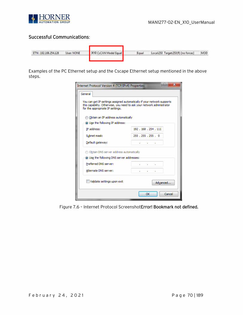
MAN1277-02-EN_X10_UserManual
F e b r u a r y 2 4 , 2 0 2 1 P a g e 70 | 189
Successful Communications:
Examples of the PC Ethernet setup and the Cscape Ethernet setup mentioned in the above steps.
Figure 7.6 – Internet Protocol ScreenshotError! Bookmark not defined.
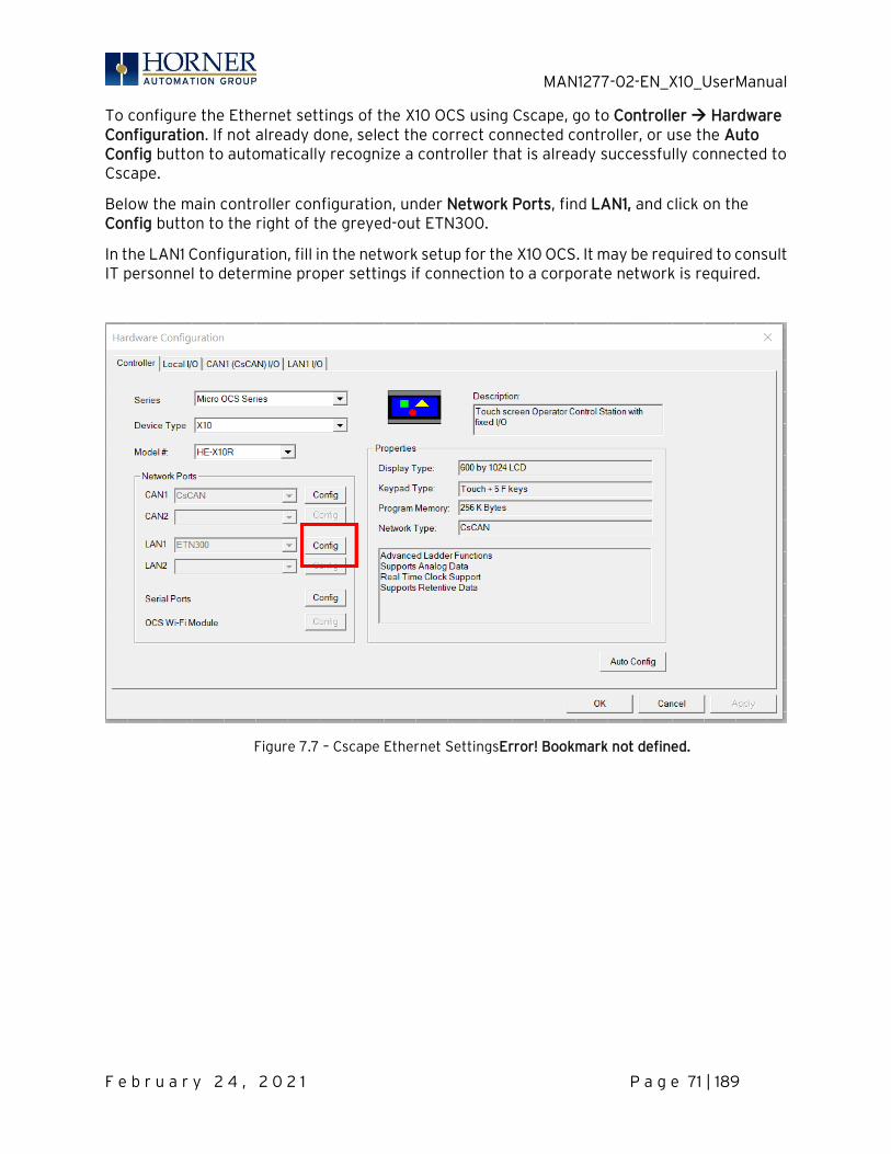
MAN1277-02-EN_X10_UserManual
F e b r u a r y 2 4 , 2 0 2 1 P a g e 71 | 189
To configure the Ethernet settings of the X10 OCS using Cscape, go to Controller → Hardware Configuration. If not already done, select the correct connected controller, or use the Auto Config button to automatically recognize a controller that is already successfully connected to Cscape.
Below the main controller configuration, under Network Ports, find LAN1, and click on the Config button to the right of the greyed-out ETN300.
In the LAN1 Configuration, fill in the network setup for the X10 OCS. It may be required to consult IT personnel to determine proper settings if connection to a corporate network is required.
Figure 7.7 – Cscape Ethernet SettingsError! Bookmark not defined.
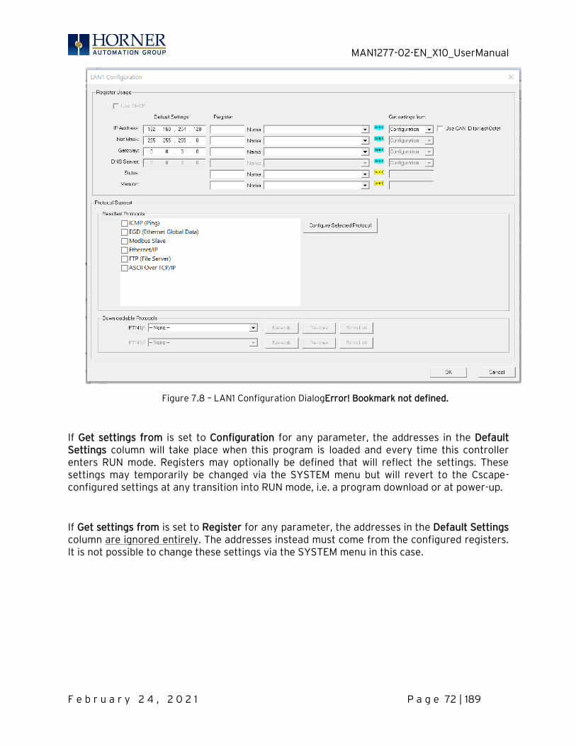
MAN1277-02-EN_X10_UserManual
F e b r u a r y 2 4 , 2 0 2 1 P a g e 72 | 189
Figure 7.8 – LAN1 Configuration DialogError! Bookmark not defined.
If Get settings from is set to Configuration for any parameter, the addresses in the Default Settings column will take place when this program is loaded and every time this controller enters RUN mode. Registers may optionally be defined that will reflect the settings. These settings may temporarily be changed via the SYSTEM menu but will revert to the Cscape-configured settings at any transition into RUN mode, i.e. a program download or at power-up.
If Get settings from is set to Register for any parameter, the addresses in the Default Settings column are ignored entirely. The addresses instead must come from the configured registers. It is not possible to change these settings via the SYSTEM menu in this case.
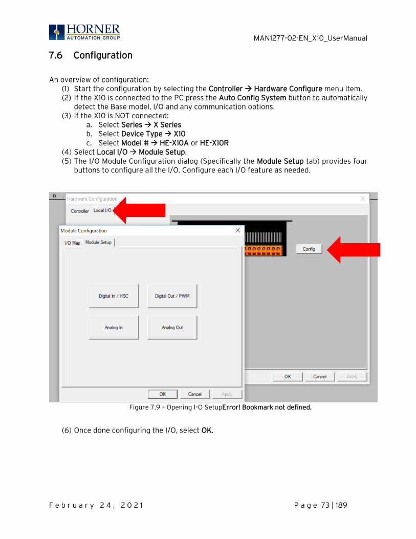
MAN1277-02-EN_X10_UserManual
F e b r u a r y 2 4 , 2 0 2 1 P a g e 73 | 189
7.6 Configuration
An overview of configuration:
(1) Start the configuration by selecting the Controller → Hardware Configure menu item. (2) If the X10 is connected to the PC press the Auto Config System button to automatically
detect the Base model, I/O and any communication options. (3) If the X10 is NOT connected:
a. Select Series → X Series b. Select Device Type → X10 c. Select Model # → HE-X10A or HE-X10R
(4) Select Local I/O → Module Setup. (5) The I/O Module Configuration dialog (Specifically the Module Setup tab) provides four
buttons to configure all the I/O. Configure each I/O feature as needed.
Figure 7.9 – Opening I-O SetupError! Bookmark not defined.
(6) Once done configuring the I/O, select OK.
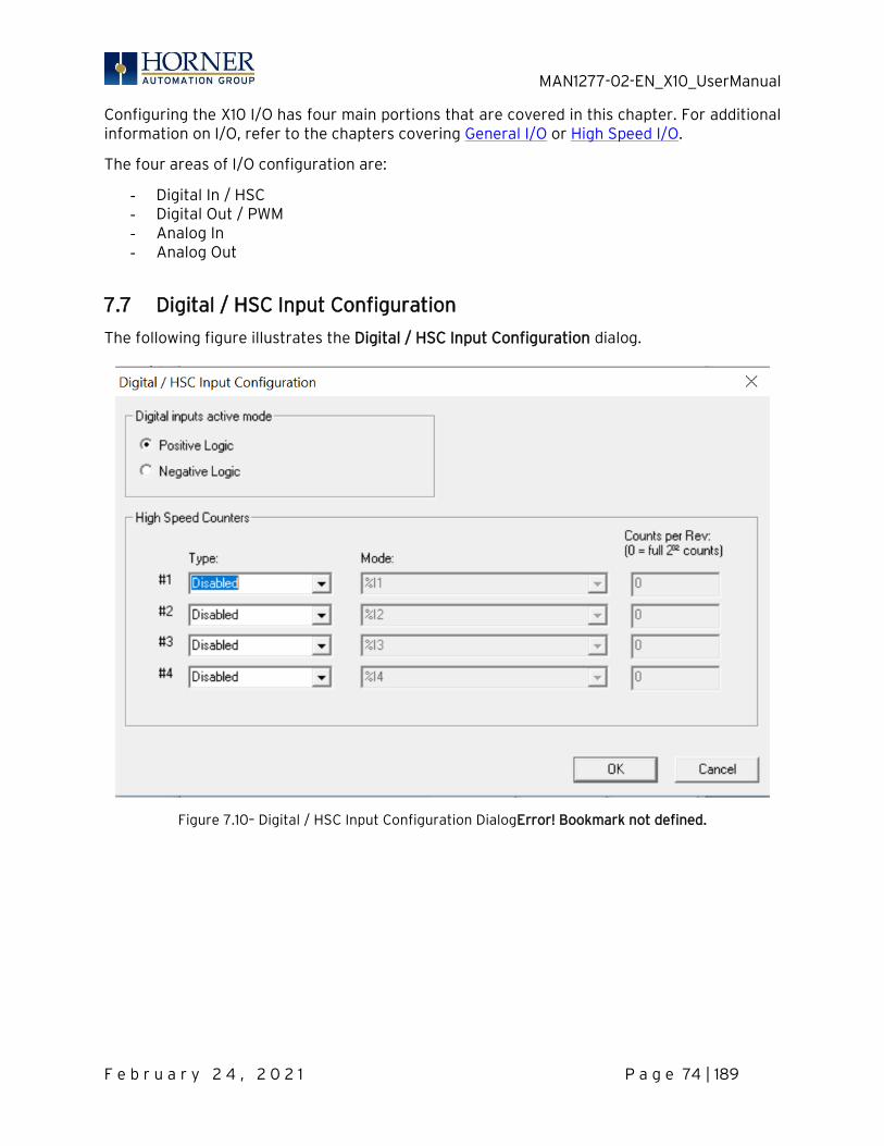
MAN1277-02-EN_X10_UserManual
F e b r u a r y 2 4 , 2 0 2 1 P a g e 74 | 189
Configuring the X10 I/O has four main portions that are covered in this chapter. For additional information on I/O, refer to the chapters covering General I/O or High Speed I/O.
The four areas of I/O configuration are:
- Digital In / HSC - Digital Out / PWM - Analog In - Analog Out
7.7 Digital / HSC Input Configuration
The following figure illustrates the Digital / HSC Input Configuration dialog.
Figure 7.10– Digital / HSC Input Configuration DialogError! Bookmark not defined.
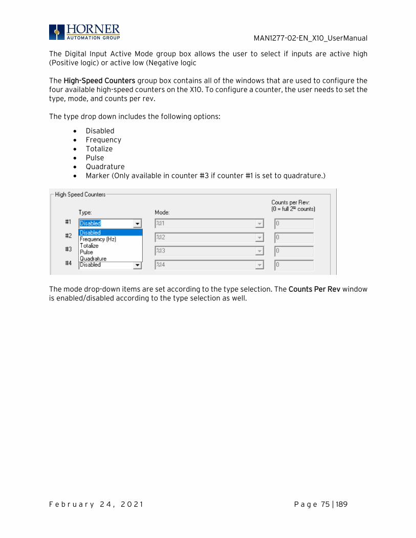
MAN1277-02-EN_X10_UserManual
F e b r u a r y 2 4 , 2 0 2 1 P a g e 75 | 189
The Digital Input Active Mode group box allows the user to select if inputs are active high (Positive logic) or active low (Negative logic The High-Speed Counters group box contains all of the windows that are used to configure the four available high-speed counters on the X10. To configure a counter, the user needs to set the type, mode, and counts per rev. The type drop down includes the following options:
• Disabled • Frequency • Totalize • Pulse • Quadrature • Marker (Only available in counter #3 if counter #1 is set to quadrature.)
The mode drop-down items are set according to the type selection. The Counts Per Rev window is enabled/disabled according to the type selection as well.
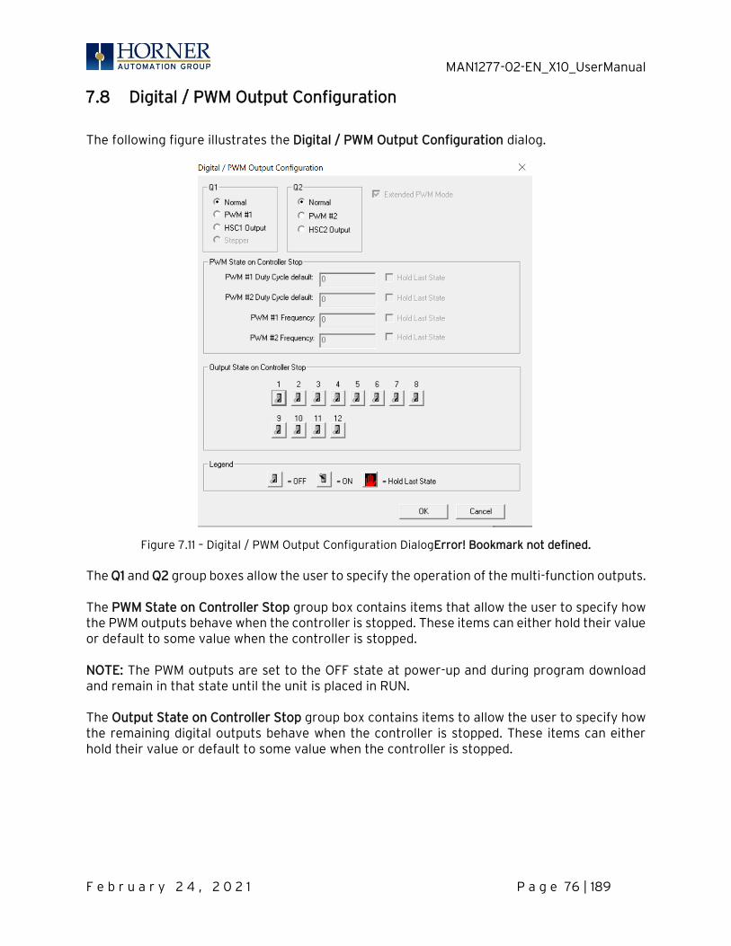
MAN1277-02-EN_X10_UserManual
F e b r u a r y 2 4 , 2 0 2 1 P a g e 76 | 189
7.8 Digital / PWM Output Configuration
The following figure illustrates the Digital / PWM Output Configuration dialog.
Figure 7.11 – Digital / PWM Output Configuration DialogError! Bookmark not defined. The Q1 and Q2 group boxes allow the user to specify the operation of the multi-function outputs. The PWM State on Controller Stop group box contains items that allow the user to specify how the PWM outputs behave when the controller is stopped. These items can either hold their value or default to some value when the controller is stopped. NOTE: The PWM outputs are set to the OFF state at power-up and during program download and remain in that state until the unit is placed in RUN. The Output State on Controller Stop group box contains items to allow the user to specify how the remaining digital outputs behave when the controller is stopped. These items can either hold their value or default to some value when the controller is stopped.
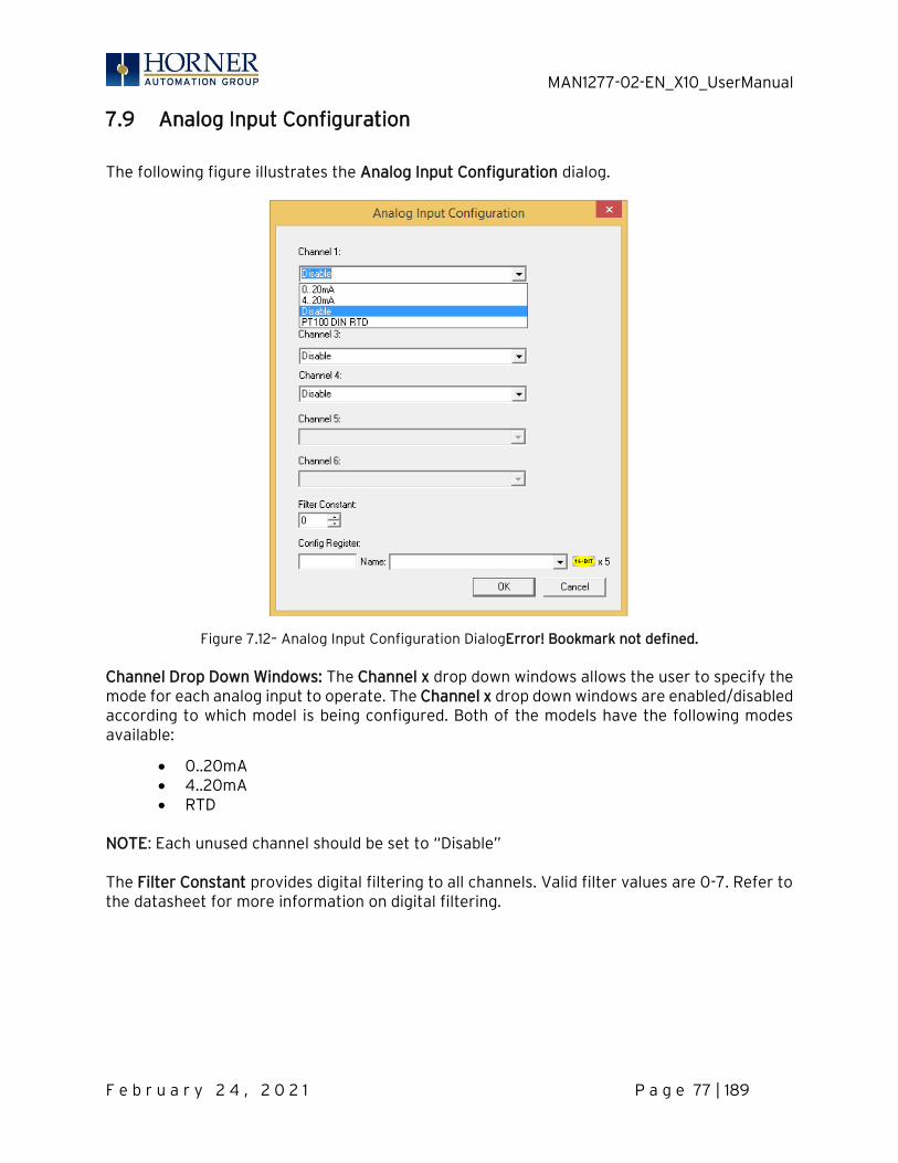
MAN1277-02-EN_X10_UserManual
F e b r u a r y 2 4 , 2 0 2 1 P a g e 77 | 189
7.9 Analog Input Configuration
The following figure illustrates the Analog Input Configuration dialog.
Figure 7.12– Analog Input Configuration DialogError! Bookmark not defined. Channel Drop Down Windows: The Channel x drop down windows allows the user to specify the mode for each analog input to operate. The Channel x drop down windows are enabled/disabled according to which model is being configured. Both of the models have the following modes available:
• 0..20mA • 4..20mA • RTD
NOTE: Each unused channel should be set to “Disable” The Filter Constant provides digital filtering to all channels. Valid filter values are 0-7. Refer to the datasheet for more information on digital filtering.
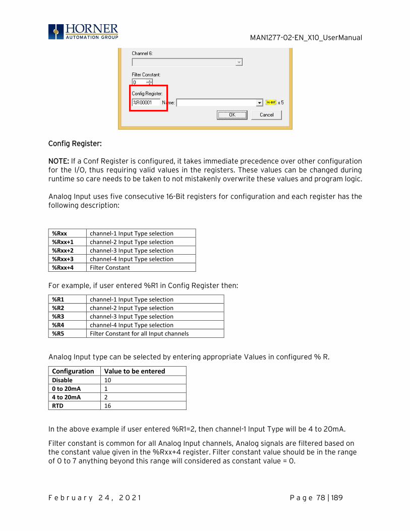
MAN1277-02-EN_X10_UserManual
F e b r u a r y 2 4 , 2 0 2 1 P a g e 78 | 189
Config Register: NOTE: If a Conf Register is configured, it takes immediate precedence over other configuration for the I/O, thus requiring valid values in the registers. These values can be changed during runtime so care needs to be taken to not mistakenly overwrite these values and program logic. Analog Input uses five consecutive 16-Bit registers for configuration and each register has the following description:
%Rxx channel-1 Input Type selection
%Rxx+1 channel-2 Input Type selection
%Rxx+2 channel-3 Input Type selection
%Rxx+3 channel-4 Input Type selection
%Rxx+4 Filter Constant
For example, if user entered %R1 in Config Register then:
%R1 channel-1 Input Type selection
%R2 channel-2 Input Type selection
%R3 channel-3 Input Type selection
%R4 channel-4 Input Type selection
%R5 Filter Constant for all Input channels
Analog Input type can be selected by entering appropriate Values in configured % R.
Configuration Value to be entered Disable 10
0 to 20mA 1
4 to 20mA 2
RTD 16
In the above example if user entered %R1=2, then channel-1 Input Type will be 4 to 20mA.
Filter constant is common for all Analog Input channels, Analog signals are filtered based on the constant value given in the %Rxx+4 register. Filter constant value should be in the range of 0 to 7 anything beyond this range will considered as constant value = 0.
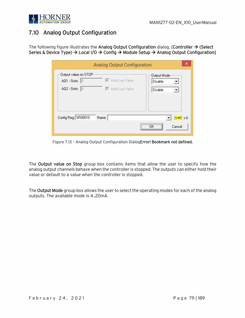
MAN1277-02-EN_X10_UserManual
F e b r u a r y 2 4 , 2 0 2 1 P a g e 79 | 189
7.10 Analog Output Configuration
The following figure illustrates the Analog Output Configuration dialog. [Controller → (Select Series & Device Type) → Local I/O → Config → Module Setup → Analog Output Configuration]
Figure 7.13 – Analog Output Configuration DialogError! Bookmark not defined.
The Output value on Stop group box contains items that allow the user to specify how the analog output channels behave when the controller is stopped. The outputs can either hold their value or default to a value when the controller is stopped. The Output Mode group box allows the user to select the operating modes for each of the analog outputs. The available mode is 4..20mA.
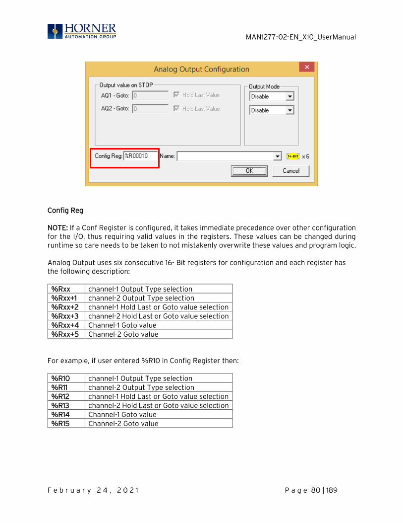
MAN1277-02-EN_X10_UserManual
F e b r u a r y 2 4 , 2 0 2 1 P a g e 80 | 189
Config Reg NOTE: If a Conf Register is configured, it takes immediate precedence over other configuration for the I/O, thus requiring valid values in the registers. These values can be changed during runtime so care needs to be taken to not mistakenly overwrite these values and program logic. Analog Output uses six consecutive 16- Bit registers for configuration and each register has the following description: %Rxx channel-1 Output Type selection %Rxx+1 channel-2 Output Type selection %Rxx+2 channel-1 Hold Last or Goto value selection %Rxx+3 channel-2 Hold Last or Goto value selection %Rxx+4 Channel-1 Goto value %Rxx+5 Channel-2 Goto value
For example, if user entered %R10 in Config Register then: %R10 channel-1 Output Type selection %R11 channel-2 Output Type selection %R12 channel-1 Hold Last or Goto value selection %R13 channel-2 Hold Last or Goto value selection %R14 Channel-1 Goto value %R15 Channel-2 Goto value

MAN1277-02-EN_X10_UserManual
F e b r u a r y 2 4 , 2 0 2 1 P a g e 81 | 189
Analog Output type can be selected by entering appropriate Values in configured %R. Configuration Value to be entered Disable 10 4 to 20mA 2
In the above example, if user entered %R10=2, then Analog Output -1 type will be 4 to 20mA. Analog Output Hold last state or Goto value can be selected by entering appropriate values in configured %R. Configuration Value to be entered %Rxx+2 0 –Hold Last value of Analog output 1—Go to value in %Rxx+4 to Analog output -1 %Rxx+3 0 –Hold Last value of Analog output 1—Go to value in %Rxx+5 to Analog output -2
In the above example, if user entered %R12=0, then Analog Output channel-1 will hold the last value when controller is in Idle mode.
In the above example, if user entered %R12=1 and %R14=12000, then Analog output channel-1 will Go to value 12000 when controller is in Idle mode.
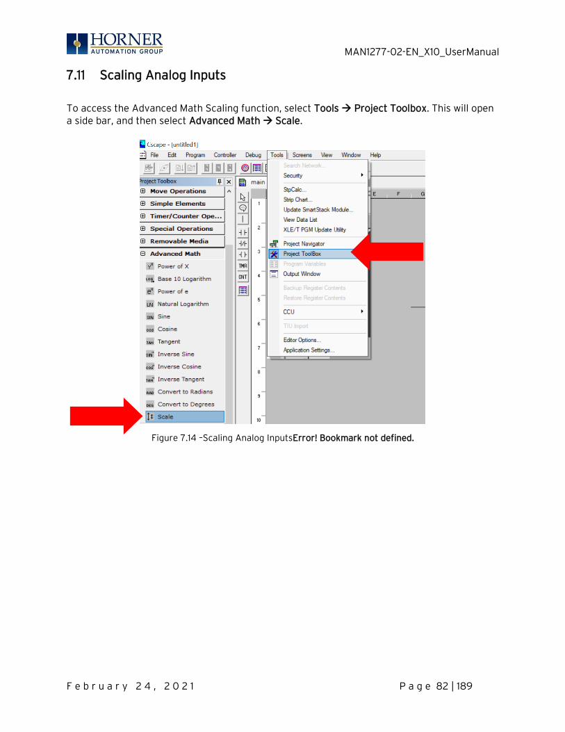
MAN1277-02-EN_X10_UserManual
F e b r u a r y 2 4 , 2 0 2 1 P a g e 82 | 189
7.11 Scaling Analog Inputs
To access the Advanced Math Scaling function, select Tools → Project Toolbox. This will open a side bar, and then select Advanced Math → Scale.
Figure 7.14 –Scaling Analog InputsError! Bookmark not defined.
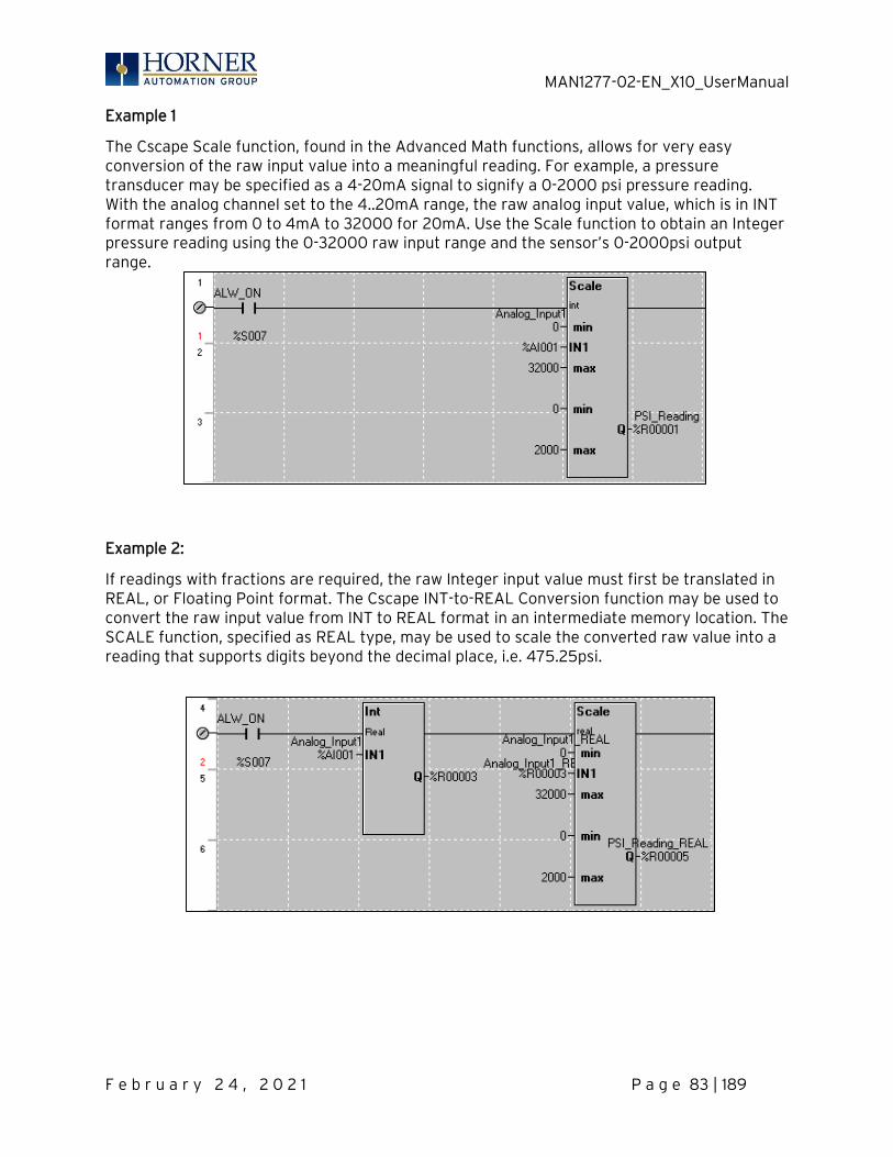
MAN1277-02-EN_X10_UserManual
F e b r u a r y 2 4 , 2 0 2 1 P a g e 83 | 189
Example 1
The Cscape Scale function, found in the Advanced Math functions, allows for very easy conversion of the raw input value into a meaningful reading. For example, a pressure transducer may be specified as a 4-20mA signal to signify a 0-2000 psi pressure reading. With the analog channel set to the 4..20mA range, the raw analog input value, which is in INT format ranges from 0 to 4mA to 32000 for 20mA. Use the Scale function to obtain an Integer pressure reading using the 0-32000 raw input range and the sensor’s 0-2000psi output range.
Example 2:
If readings with fractions are required, the raw Integer input value must first be translated in REAL, or Floating Point format. The Cscape INT-to-REAL Conversion function may be used to convert the raw input value from INT to REAL format in an intermediate memory location. The SCALE function, specified as REAL type, may be used to scale the converted raw value into a reading that supports digits beyond the decimal place, i.e. 475.25psi.

MAN1277-02-EN_X10_UserManual
F e b r u a r y 2 4 , 2 0 2 1 P a g e 84 | 189
CHAPTER 8: GENERAL I/O NOTE: Each X10 unit is shipped with a datasheet in the box. The datasheet [MAN1278] is the first document to refer to for model-specific information related to X10 models. Visit the website to obtain datasheets, user documentation, and updates. North America https://hornerautomation.com Europe www.hornerautomation.eu
8.1 Overview
The X10 is a compact unit that contains high density and very versatile I/O. Using the I/O properly requires wiring to the proper terminals and configuring Cscape properly. This section will offer some tips and suggestions to configure the I/O properly. For the register mapping of the I/O, refer to the Registers chapter. NOTE: To remove remote I/O connectors, gently pry up the connectors with a small flathead screwdriver.
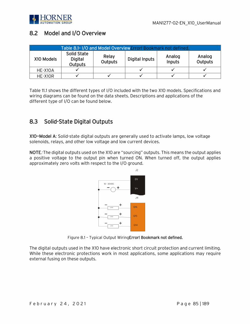
MAN1277-02-EN_X10_UserManual
F e b r u a r y 2 4 , 2 0 2 1 P a g e 85 | 189
8.2 Model and I/O Overview
Table 8.1– I/O and Model OverviewError! Bookmark not defined.
X10 Models Solid State
Digital Outputs
Relay Outputs
Digital Inputs Analog Inputs
Analog Outputs
HE-X10A HE-X10R
Table 11.1 shows the different types of I/O included with the two X10 models. Specifications and wiring diagrams can be found on the data sheets. Descriptions and applications of the different type of I/O can be found below.
8.3 Solid-State Digital Outputs
X10—Model A: Solid-state digital outputs are generally used to activate lamps, low voltage solenoids, relays, and other low voltage and low current devices. NOTE: The digital outputs used on the X10 are “sourcing” outputs. This means the output applies a positive voltage to the output pin when turned ON. When turned off, the output applies approximately zero volts with respect to the I/O ground.
Figure 8.1 – Typical Output WiringError! Bookmark not defined. The digital outputs used in the X10 have electronic short circuit protection and current limiting. While these electronic protections work in most applications, some applications may require external fusing on these outputs.
Q14
Q15
V+
0V
LOAD
LOAD
10 - 30VDC
Q16 LOAD
J2
J4
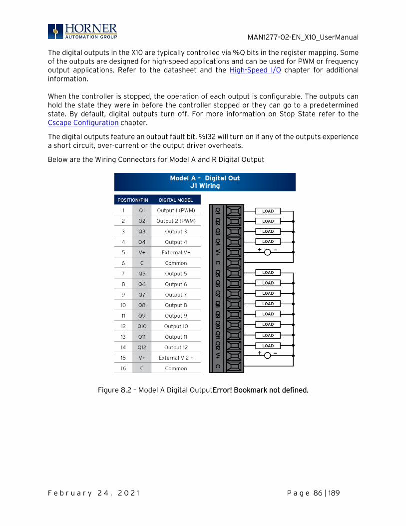
MAN1277-02-EN_X10_UserManual
F e b r u a r y 2 4 , 2 0 2 1 P a g e 86 | 189
The digital outputs in the X10 are typically controlled via %Q bits in the register mapping. Some of the outputs are designed for high-speed applications and can be used for PWM or frequency output applications. Refer to the datasheet and the High-Speed I/O chapter for additional information. When the controller is stopped, the operation of each output is configurable. The outputs can hold the state they were in before the controller stopped or they can go to a predetermined state. By default, digital outputs turn off. For more information on Stop State refer to the Cscape Configuration chapter.
The digital outputs feature an output fault bit. %I32 will turn on if any of the outputs experience a short circuit, over-current or the output driver overheats.
Below are the Wiring Connectors for Model A and R Digital Output
Figure 8.2 – Model A Digital OutputError! Bookmark not defined.
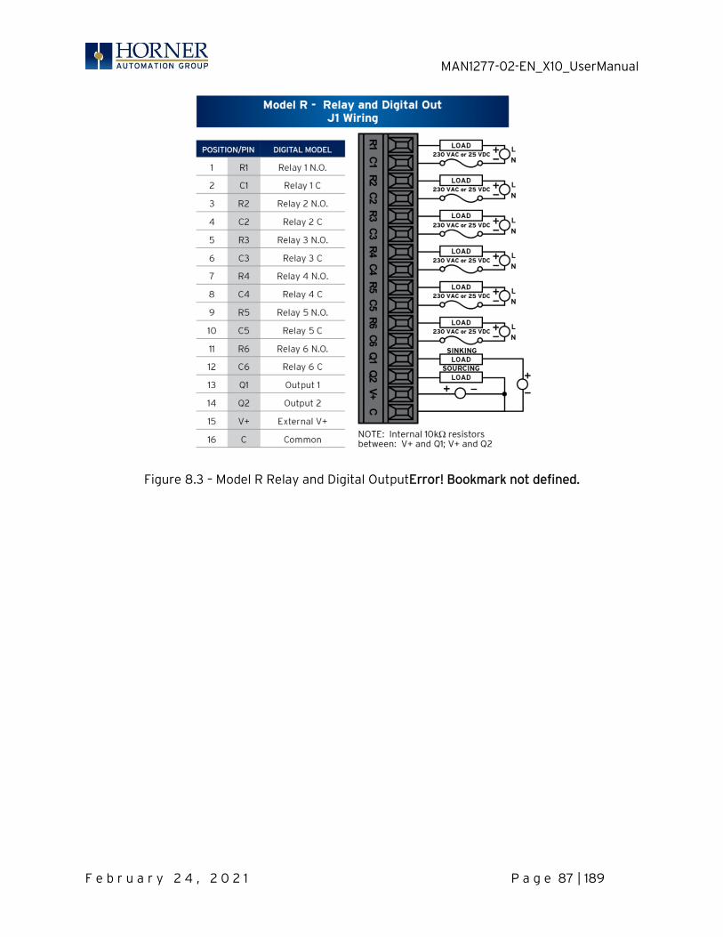
MAN1277-02-EN_X10_UserManual
F e b r u a r y 2 4 , 2 0 2 1 P a g e 87 | 189
Figure 8.3 – Model R Relay and Digital OutputError! Bookmark not defined.
MAN1277-02-EN_X10_UserManual
F e b r u a r y 2 4 , 2 0 2 1 P a g e 88 | 189
8.4 Relay Outputs
Relay outputs are designed to switch loads that typically have high voltage or current requirements or require isolation that relays provide. NOTE: The design of the X10 does not require external coil power for the relays to function. The relays may be activated as long as the X10 is powered. There are several factors that should be considered when using relays.
• Relay Life – Relays are mechanical devices that have a long but limited life. Typically switching more current limits the life of relays. Please check the datasheet [MAN1156] for expected relay life.
• Current / Temperature De-Rating – Products containing relays often have total current limits based on the ambient temperature of the application. Please see the product data sheet for current / temperature de-rating information for relays.
• Fusing – External fusing is generally required to protect the relays, devices and wiring from shorts or overloads.
Protection for Inductive Loads – Inductive loads can cause reverse currents when they turn off that can shorten the life of relay contacts. Some protective measures must be determined by an engineer. Below are some recommendations that will work for many applications. If there are additional questions on protection from inductive load, consult Horner Technical Support.
DC Loads – General purpose diode (IN4004) in reverse bias across the load.
AC Load – MOV (Harris V140xxx for 120V, V275xx for 220V)
Output State on Controller Stop – When the controller is stopped the operation of each output is configurable. The outputs can hold the state they were in before the controller stopped or they can go to a predetermined state. By default, relay outputs turn off. For more information on stop state, refer to the Cscape Configuration chapter for Cscape settings.
WARNING: To protect the module and associated wiring from load faults, use external (5A)
fuse(s) as shown. Fuses of lower current or fusing for the entire system must be in place to ensure that the maximum current rating of the unit is not exceeded.
WARNING: Connecting high voltage to any I/O pin can cause high voltage to appear at other I/O pins.
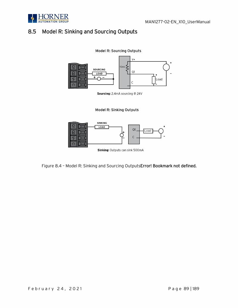
MAN1277-02-EN_X10_UserManual
F e b r u a r y 2 4 , 2 0 2 1 P a g e 89 | 189
8.5 Model R: Sinking and Sourcing Outputs
Figure 8.4 – Model R: Sinking and Sourcing OutputsError! Bookmark not defined.
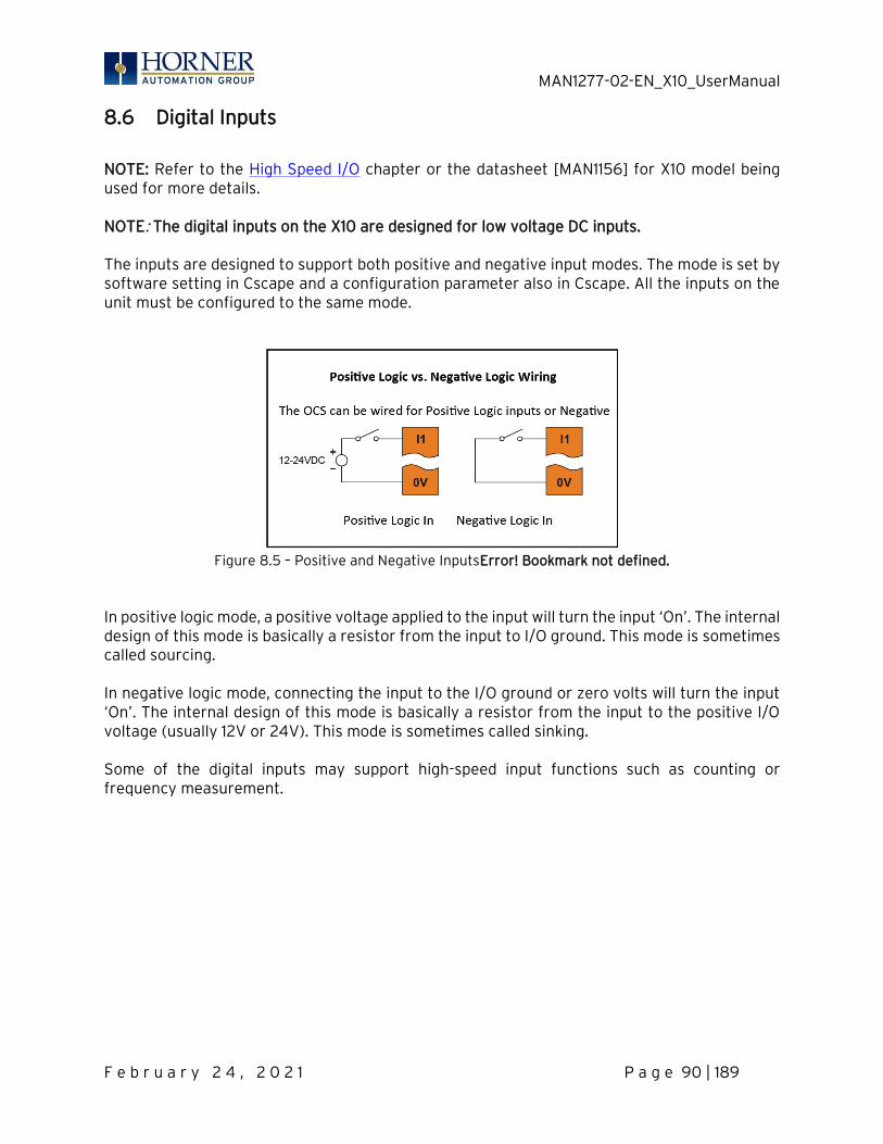
MAN1277-02-EN_X10_UserManual
F e b r u a r y 2 4 , 2 0 2 1 P a g e 90 | 189
8.6 Digital Inputs
NOTE: Refer to the High Speed I/O chapter or the datasheet [MAN1156] for X10 model being used for more details. NOTE: The digital inputs on the X10 are designed for low voltage DC inputs. The inputs are designed to support both positive and negative input modes. The mode is set by software setting in Cscape and a configuration parameter also in Cscape. All the inputs on the unit must be configured to the same mode.
Figure 8.5 – Positive and Negative InputsError! Bookmark not defined.
In positive logic mode, a positive voltage applied to the input will turn the input ‘On’. The internal design of this mode is basically a resistor from the input to I/O ground. This mode is sometimes called sourcing. In negative logic mode, connecting the input to the I/O ground or zero volts will turn the input ‘On’. The internal design of this mode is basically a resistor from the input to the positive I/O voltage (usually 12V or 24V). This mode is sometimes called sinking. Some of the digital inputs may support high-speed input functions such as counting or frequency measurement.
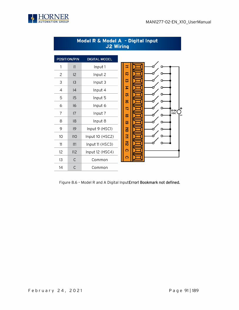
MAN1277-02-EN_X10_UserManual
F e b r u a r y 2 4 , 2 0 2 1 P a g e 91 | 189
Figure 8.6 – Model R and A Digital InputError! Bookmark not defined.

MAN1277-02-EN_X10_UserManual
F e b r u a r y 2 4 , 2 0 2 1 P a g e 92 | 189
8.7 Analog Inputs
NOTE: Refer to the High Speed I/O chapter or the datasheet for X10 model being used for more details. The analog inputs on the X10 allow current measurement from a variety of devices. The analog inputs have a digital filter that can be used to filter electrical noise that may be unavoidable in some installations. The downside to digital filtering is the inputs will respond more slowly to sudden changes in the actual input.
8.8 I/O Status and Calibration
8.8.1 I/O Status The I and Q sections indicate the ON and OFF status of the individual digital inputs and outputs respectively. The AI values show the raw analog inputs scaled from 0 to 32,000. The AQ items show the raw analog outputs scaled from 0 to 32,000. The X10 System Menu contains an “I/O Status and Calibration” selection.
When first entering this option, the user is presented with information about the X10 model and current state of the I-O points.
Model: XE-X10R
I12-1: 000000000000
Q12-1: 000000000000
AI1: 12345
AI2: 456
AI3: 789
AI4: 32100
AQ1: 33333
AQ2: 11111
Calibrate Analog
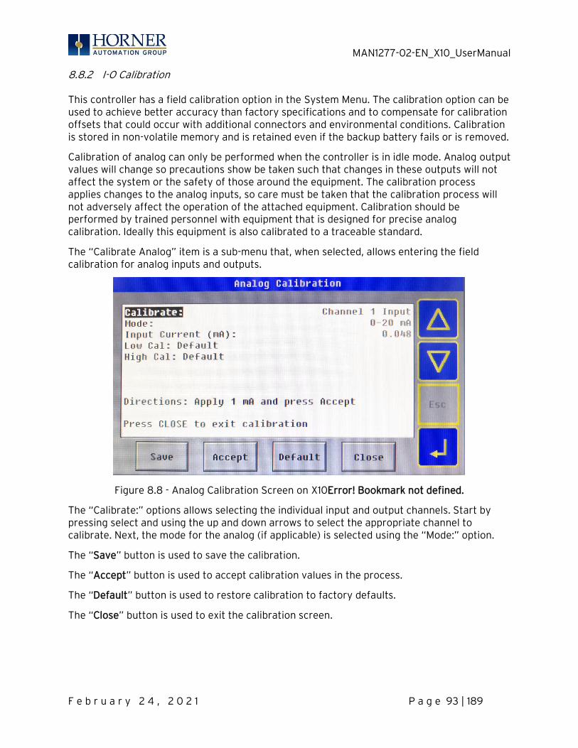
MAN1277-02-EN_X10_UserManual
F e b r u a r y 2 4 , 2 0 2 1 P a g e 93 | 189
8.8.2 I-O Calibration This controller has a field calibration option in the System Menu. The calibration option can be used to achieve better accuracy than factory specifications and to compensate for calibration offsets that could occur with additional connectors and environmental conditions. Calibration is stored in non-volatile memory and is retained even if the backup battery fails or is removed.
Calibration of analog can only be performed when the controller is in idle mode. Analog output values will change so precautions show be taken such that changes in these outputs will not affect the system or the safety of those around the equipment. The calibration process applies changes to the analog inputs, so care must be taken that the calibration process will not adversely affect the operation of the attached equipment. Calibration should be performed by trained personnel with equipment that is designed for precise analog calibration. Ideally this equipment is also calibrated to a traceable standard.
The “Calibrate Analog” item is a sub-menu that, when selected, allows entering the field calibration for analog inputs and outputs.
Figure 8.8 - Analog Calibration Screen on X10Error! Bookmark not defined.
The “Calibrate:” options allows selecting the individual input and output channels. Start by pressing select and using the up and down arrows to select the appropriate channel to calibrate. Next, the mode for the analog (if applicable) is selected using the “Mode:” option.
The “Save” button is used to save the calibration.
The “Accept” button is used to accept calibration values in the process.
The “Default” button is used to restore calibration to factory defaults.
The “Close” button is used to exit the calibration screen.

MAN1277-02-EN_X10_UserManual
F e b r u a r y 2 4 , 2 0 2 1 P a g e 94 | 189
8.8.1 To calibrate 0-20mA, 4-20mA or RTD PT100 Analog Inputs: NOTE: During Calibration process, the application may be placed in Idle.
1) Select the channel and mode as described above 2) Connect the analog channel to be calibrated to the calibration equipment. 3) Apply the lower current or RTD value as directed by the screen to the selected analog
input channel. 4) Once the value on the screen is stable press the Accept button. 5) Apply the higher current or RTD value. 6) Move on to additional channels and repeat the above five steps. 7) Make sure to press Save when all channels are calibrated.
8.8.2 To calibrate 4-20mA Analog Outputs: NOTE: During Calibration process, the application may be placed in Idle.
1) Select the channel and mode as described above 2) Connect the analog output to be calibrated to a calibrator or precision meter. 3) The controller will set the output to a lower analog output value. 4) Read the value from the calibrator and enter it into the “Output Current:” item on the
menu. 5) Press Accept. 6) The controller will set the output to a higher analog output value. 7) Read the value from the calibrator and enter it into the “Output Current:” item on the
menu. 8) Press Accept. 9) Move on to additional channels and repeat the above eight steps. 10) Make sure to press Save when all channels are calibrated.
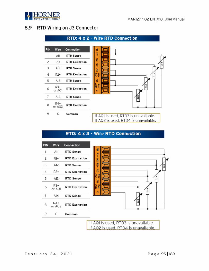
MAN1277-02-EN_X10_UserManual
F e b r u a r y 2 4 , 2 0 2 1 P a g e 95 | 189
8.9 RTD Wiring on J3 Connector
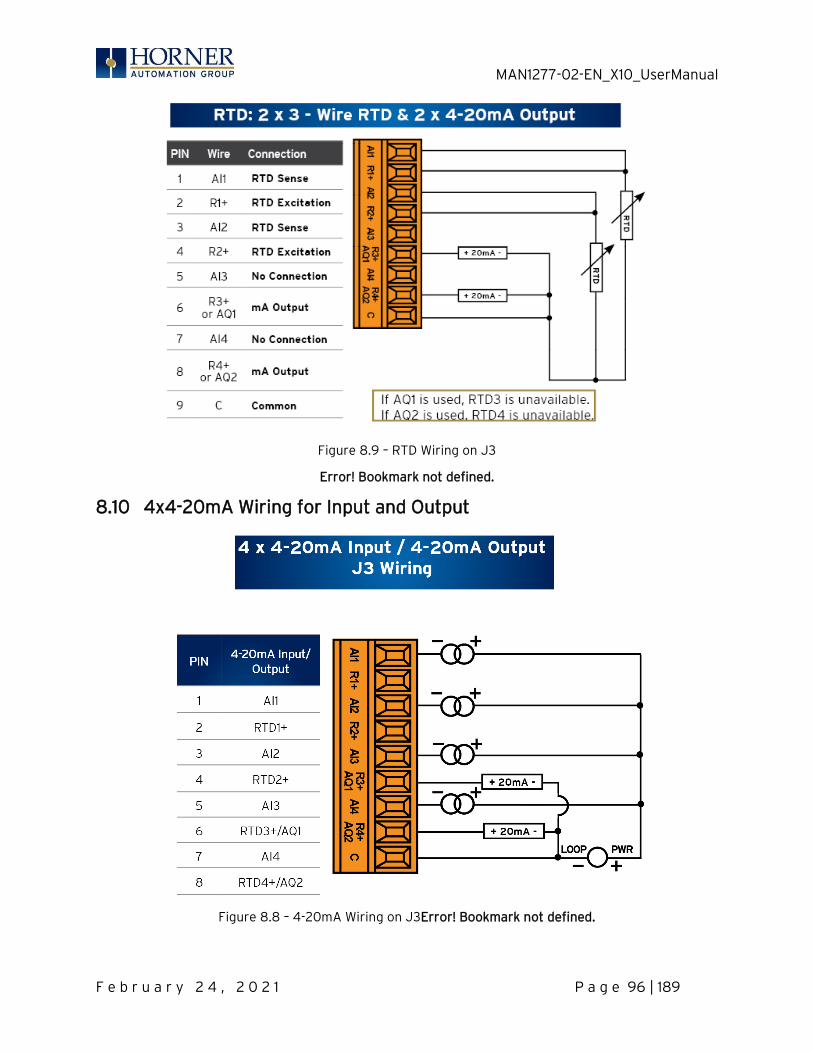
MAN1277-02-EN_X10_UserManual
F e b r u a r y 2 4 , 2 0 2 1 P a g e 96 | 189
Figure 8.9 – RTD Wiring on J3
Error! Bookmark not defined.
8.10 4x4-20mA Wiring for Input and Output
Figure 8.8 – 4-20mA Wiring on J3Error! Bookmark not defined.

MAN1277-02-EN_X10_UserManual
F e b r u a r y 2 4 , 2 0 2 1 P a g e 97 | 189
8.11 Analog Outputs
NOTE: Refer to the High Speed I/O chapter or the datasheet [MAN1278] for X10 model being used for more details. The analog outputs on X10 devices provide high resolution current outputs. NOTE: Each channel can be separately configured for current mode. When the controller is stopped, the operation of each output is configurable. The outputs can hold the state they were in before the controller stopped or they can go to a predetermined value. By default, analog outputs are set to a value of zero (0). For more information on Stop State, refer to the Cscape Configuration chapter.

MAN1277-02-EN_X10_UserManual
F e b r u a r y 2 4 , 2 0 2 1 P a g e 98 | 189
CHAPTER 9: HIGH SPEED I/O (HSC/PWM)
9.1 Overview
In addition to the compliment of simple analog and digital I/O, the X10 supports High Speed Counting (HSC) I/O functions and may support Pulse Width Modulation (PWM) Output functions. The HSC functions include frequency, totalizing, pulse width, and quadrature measurement. The PWM functions include traditional PWM (with variable rate and duty) with variable acceleration and deceleration rates. To determine function availability, refer to the associated model’s Specification/Installation sheet (Digital DC Input/Output sections). This chapter describes the operation of these high level I/O functions. For configuration details of these functions, refer to the Cscape Configuration chapter.
9.2 Glossary of High Speed I/O Terms
Table 9.1 – Glossary of High Speed I/O TermsError! Bookmark not defined.
Accumulator Register used to accumulate or store up a sum or count of many items or events.
Clear A special function to zero out the value in a specific register. (Not used with Frequency or Period Measurement.)
Disable A special function to prevent the counter from running.
Encoder A sensor or transducer for converting rotary motion or position to a series of electronic pulses
Frequency Input
The number of times an electromagnetic signal repeats an identical cycle in a unit of time, usually one second.
Latch (strobe)
A special function that uses a digital logic circuit to store one or more bits. A latch has a data input, a clock input and an output. When the clock input is active, data on the input is "latched" or stored and transferred to the output register either immediately or when the clock input goes inactive. The output retains its value until the clock goes active again.
Marker Input into the OCS that indicates a particular position. Typically, an encoder has a marker output that represents a specific point in the rotation.
Polarity A Polarity pull-down box is associated with each function and indicates the manner in which the trigger happens (e.g., High level, Low Level, Falling Edge, Rising Edge).
Preload (load)
A special function used to trigger loading of a value into a register upon an event. (Not used with Frequency or Period Measurement.)
Quadrature A high-speed device that expresses the phase relationship between two periodic quantities of the same period when the phase difference between them is one fourth of a period. A coupler in which the two output signals are 90° out of phase.
Totalizer A counter that sums the total number of cycles applied to its input.

MAN1277-02-EN_X10_UserManual
F e b r u a r y 2 4 , 2 0 2 1 P a g e 99 | 189
9.3 High Speed Counter (HSC) Functions
Four dedicated inputs are available that can be configured for one of four modes of operation. Those modes are Frequency, Count (totalize), Pulse width or period (pulse) and Quadrature measurement. For some modes, more than one HSC input may be consumed. The measurement value is provided to ladder in a %AI register. NOTE: While the high-speed input circuitry has a resolution of 1μs, measured edge transitions must not occur faster than 100μs for accurate measurements. Keep in mind that pulse width measurements utilize both the rising and falling edges of the waveform, thus the pulse width must exist longer than 100μs. NOTE: The edge polarity selection in the mode parameter for the totalize and pulse width functions (Digital/HSC Input Configuration) assume Positive Logic regardless of the associated I/O board’s jumper setting for the Digital DC inputs polarity. If Negative logic is configured when using these functions, the opposite edge polarity must be selected in the mode parameter.
9.4 Frequency
In frequency mode, the frequency of the input signal is written to the accumulator in terms of Hertz (cycles/second). When using frequency mode, four update selections are provided which specify the width of the sample window.
NOTE: Selecting a shorter sample window provides a quicker measurement (faster response) but lowers the frequency accuracy (resolution) and increases the minimum frequency measurement limit.
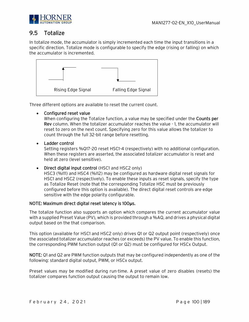
MAN1277-02-EN_X10_UserManual
F e b r u a r y 2 4 , 2 0 2 1 P a g e 100 | 189
9.5 Totalize
In totalize mode, the accumulator is simply incremented each time the input transitions in a specific direction. Totalize mode is configurable to specify the edge (rising or falling) on which the accumulator is incremented.
Three different options are available to reset the current count.
• Configured reset value When configuring the Totalize function, a value may be specified under the Counts per Rev column. When the totalizer accumulator reaches the value - 1, the accumulator will reset to zero on the next count. Specifying zero for this value allows the totalizer to count through the full 32-bit range before resetting.
• Ladder control Setting registers %Q17-20 reset HSC1-4 (respectively) with no additional configuration. When these registers are asserted, the associated totalizer accumulator is reset and held at zero (level sensitive).
• Direct digital input control (HSC1 and HSC2 only) HSC3 (%I11) and HSC4 (%I12) may be configured as hardware digital reset signals for HSC1 and HSC2 (respectively). To enable these inputs as reset signals, specify the type as Totalize Reset (note that the corresponding Totalize HSC must be previously configured before this option is available). The direct digital reset controls are edge sensitive with the edge polarity configurable.
NOTE: Maximum direct digital reset latency is 100μs.
The totalize function also supports an option which compares the current accumulator value with a supplied Preset Value (PV), which is provided through a %AQ, and drives a physical digital output based on the that comparison. This option (available for HSC1 and HSC2 only) drives Q1 or Q2 output point (respectively) once the associated totalizer accumulator reaches (or exceeds) the PV value. To enable this function, the corresponding PWM function output (Q1 or Q2) must be configured for HSCx Output.
NOTE: Q1 and Q2 are PWM function outputs that may be configured independently as one of the following: standard digital output, PWM, or HSCx output. Preset values may be modified during run-time. A preset value of zero disables (resets) the totalizer compares function output causing the output to remain low.
Rising Edge Signal Falling Edge Signal
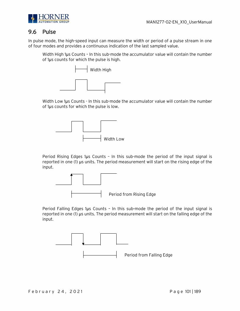
MAN1277-02-EN_X10_UserManual
F e b r u a r y 2 4 , 2 0 2 1 P a g e 101 | 189
9.6 Pulse
In pulse mode, the high-speed input can measure the width or period of a pulse stream in one of four modes and provides a continuous indication of the last sampled value.
Width High 1μs Counts – In this sub-mode the accumulator value will contain the number of 1μs counts for which the pulse is high.
Width Low 1μs Counts - In this sub-mode the accumulator value will contain the number of 1μs counts for which the pulse is low.
Period Rising Edges 1μs Counts – In this sub-mode the period of the input signal is reported in one (1) μs units. The period measurement will start on the rising edge of the input.
Period Falling Edges 1μs Counts – In this sub-mode the period of the input signal is reported in one (1) μs units. The period measurement will start on the falling edge of the input.
Width High
Width Low
Period from Rising Edge
Period from Falling Edge
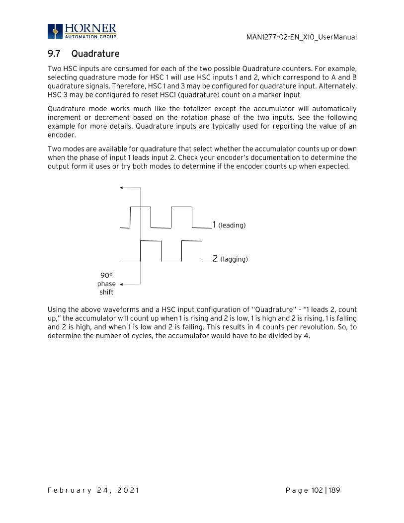
MAN1277-02-EN_X10_UserManual
F e b r u a r y 2 4 , 2 0 2 1 P a g e 102 | 189
9.7 Quadrature
Two HSC inputs are consumed for each of the two possible Quadrature counters. For example, selecting quadrature mode for HSC 1 will use HSC inputs 1 and 2, which correspond to A and B quadrature signals. Therefore, HSC 1 and 3 may be configured for quadrature input. Alternately, HSC 3 may be configured to reset HSC1 (quadrature) count on a marker input
Quadrature mode works much like the totalizer except the accumulator will automatically increment or decrement based on the rotation phase of the two inputs. See the following example for more details. Quadrature inputs are typically used for reporting the value of an encoder.
Two modes are available for quadrature that select whether the accumulator counts up or down when the phase of input 1 leads input 2. Check your encoder’s documentation to determine the output form it uses or try both modes to determine if the encoder counts up when expected.
Using the above waveforms and a HSC input configuration of “Quadrature” - “1 leads 2, count up,” the accumulator will count up when 1 is rising and 2 is low, 1 is high and 2 is rising, 1 is falling and 2 is high, and when 1 is low and 2 is falling. This results in 4 counts per revolution. So, to determine the number of cycles, the accumulator would have to be divided by 4.
90° phase shift
1 (leading)
2 (lagging)

MAN1277-02-EN_X10_UserManual
F e b r u a r y 2 4 , 2 0 2 1 P a g e 103 | 189
Three different options are available to reset (or set) the current count. They are:
• Configured Counts per Rev value When configuring the quadrature function, a value may be specified under the Counts per Rev column. When rotation produces an increasing count, the quadrature accumulator resets to zero on reaching the Counts per Rev count. Alternately, when rotation produces a decreasing count, the quadrature accumulator is set to Counts per Rev – 1 on the count following zero. Specifying zero for this value allows the totalizer to count through the full 32-bit range before resetting.
For example, if your encoder outputs 1024 counts per revolution, the value of 1024 can be entered into the configuration for Counts per rev. This will result in a counter that produces counts in the range of 0 to 1023.
• Ladder control Setting registers %Q17 or Q19 resets quadrature (HSC) 1 or quadrature (HSC) 3 (respectively) with no additional configuration. Setting registers %Q18 or Q20 sets quadrature (HSC) 1 or quadrature (HSC) 3 (respectively) to Counts per Rev – 1.
• Direct digital input control (HSC3) [Marker] When HSC input 1 and 2 are used for quadrature inputs, an additional choice of marker input becomes available for HSC input 3. The marker input is typically part of an encoder or motion system that signals when a cycle of motion is complete. When the marker input is triggered, the accumulator is reset to zero or to Counts per rev - 1 based on rotation direction. Marker reset operation is enabled when HSC3 is configured for Marker type. Once selected, one of several modes is available for marker operation. These modes can be sub-divided into two groups of marker operation.
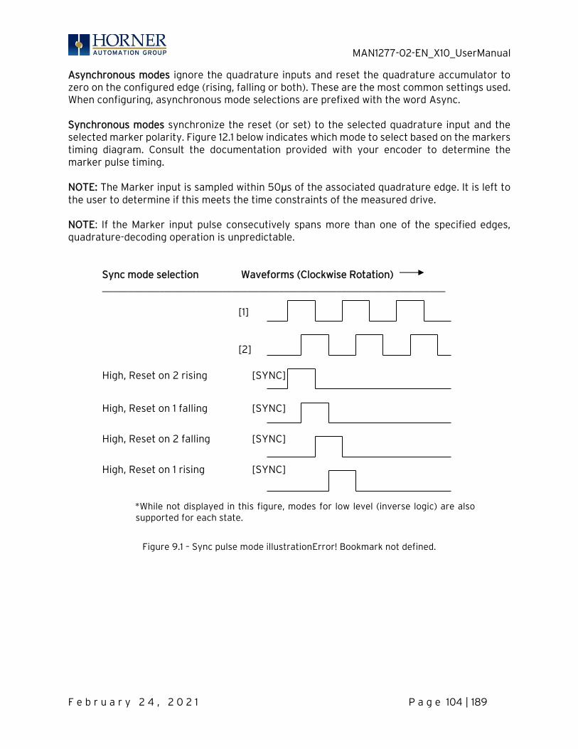
MAN1277-02-EN_X10_UserManual
F e b r u a r y 2 4 , 2 0 2 1 P a g e 104 | 189
Asynchronous modes ignore the quadrature inputs and reset the quadrature accumulator to zero on the configured edge (rising, falling or both). These are the most common settings used. When configuring, asynchronous mode selections are prefixed with the word Async. Synchronous modes synchronize the reset (or set) to the selected quadrature input and the selected marker polarity. Figure 12.1 below indicates which mode to select based on the markers timing diagram. Consult the documentation provided with your encoder to determine the marker pulse timing. NOTE: The Marker input is sampled within 50μs of the associated quadrature edge. It is left to the user to determine if this meets the time constraints of the measured drive.
NOTE: If the Marker input pulse consecutively spans more than one of the specified edges, quadrature-decoding operation is unpredictable. Sync mode selection Waveforms (Clockwise Rotation) __________________________________________________________________ [1] [2]
High, Reset on 2 rising [SYNC]
High, Reset on 1 falling [SYNC]
High, Reset on 2 falling [SYNC]
High, Reset on 1 rising [SYNC]
*While not displayed in this figure, modes for low level (inverse logic) are also supported for each state.
Figure 9.1 – Sync pulse mode illustrationError! Bookmark not defined.
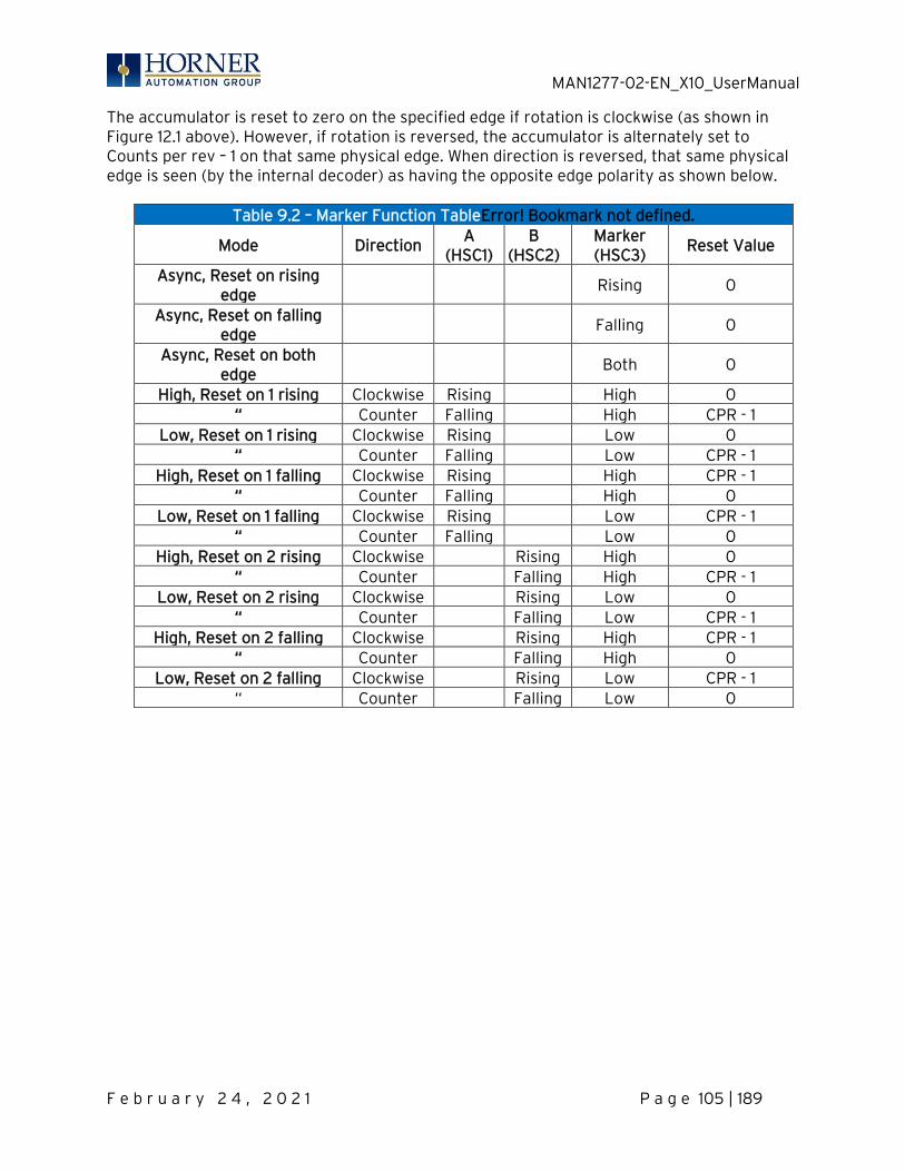
MAN1277-02-EN_X10_UserManual
F e b r u a r y 2 4 , 2 0 2 1 P a g e 105 | 189
The accumulator is reset to zero on the specified edge if rotation is clockwise (as shown in Figure 12.1 above). However, if rotation is reversed, the accumulator is alternately set to Counts per rev – 1 on that same physical edge. When direction is reversed, that same physical edge is seen (by the internal decoder) as having the opposite edge polarity as shown below.
Table 9.2 – Marker Function TableError! Bookmark not defined.
Mode Direction A
(HSC1) B
(HSC2) Marker (HSC3)
Reset Value
Async, Reset on rising edge
Rising 0
Async, Reset on falling edge
Falling 0
Async, Reset on both edge
Both 0
High, Reset on 1 rising Clockwise Rising High 0 “ Counter Falling High CPR - 1
Low, Reset on 1 rising Clockwise Rising Low 0 “ Counter Falling Low CPR - 1
High, Reset on 1 falling Clockwise Rising High CPR - 1 “ Counter Falling High 0
Low, Reset on 1 falling Clockwise Rising Low CPR - 1 “ Counter Falling Low 0
High, Reset on 2 rising Clockwise Rising High 0 “ Counter Falling High CPR - 1
Low, Reset on 2 rising Clockwise Rising Low 0 “ Counter Falling Low CPR - 1
High, Reset on 2 falling Clockwise Rising High CPR - 1 “ Counter Falling High 0
Low, Reset on 2 falling Clockwise Rising Low CPR - 1 “ Counter Falling Low 0
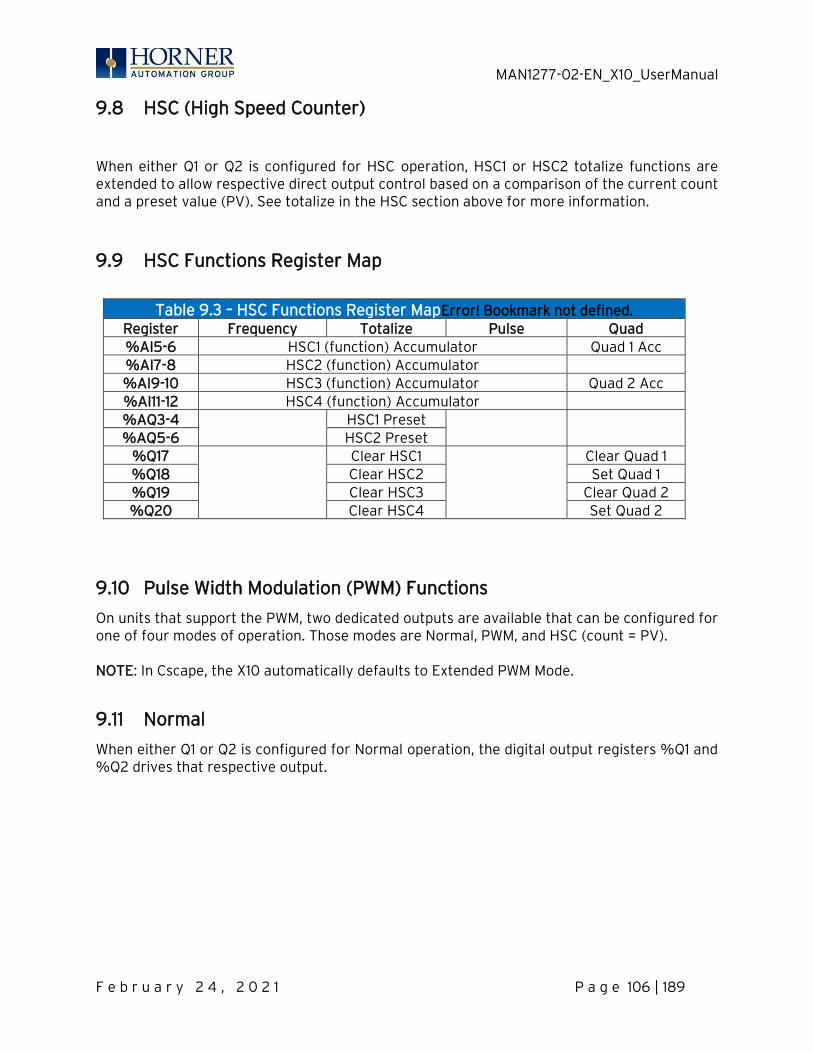
MAN1277-02-EN_X10_UserManual
F e b r u a r y 2 4 , 2 0 2 1 P a g e 106 | 189
9.8 HSC (High Speed Counter)
When either Q1 or Q2 is configured for HSC operation, HSC1 or HSC2 totalize functions are extended to allow respective direct output control based on a comparison of the current count and a preset value (PV). See totalize in the HSC section above for more information.
9.9 HSC Functions Register Map
Table 9.3 – HSC Functions Register MapError! Bookmark not defined.
Register Frequency Totalize Pulse Quad %AI5-6 HSC1 (function) Accumulator Quad 1 Acc %AI7-8 HSC2 (function) Accumulator %AI9-10 HSC3 (function) Accumulator Quad 2 Acc %AI11-12 HSC4 (function) Accumulator %AQ3-4
HSC1 Preset
%AQ5-6 HSC2 Preset
%Q17
Clear HSC1
Clear Quad 1 %Q18 Clear HSC2 Set Quad 1 %Q19 Clear HSC3 Clear Quad 2 %Q20 Clear HSC4 Set Quad 2
9.10 Pulse Width Modulation (PWM) Functions
On units that support the PWM, two dedicated outputs are available that can be configured for one of four modes of operation. Those modes are Normal, PWM, and HSC (count = PV). NOTE: In Cscape, the X10 automatically defaults to Extended PWM Mode.
9.11 Normal
When either Q1 or Q2 is configured for Normal operation, the digital output registers %Q1 and %Q2 drives that respective output.
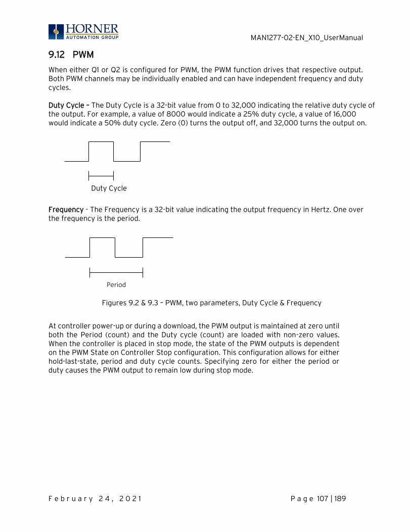
MAN1277-02-EN_X10_UserManual
F e b r u a r y 2 4 , 2 0 2 1 P a g e 107 | 189
9.12 PWM
When either Q1 or Q2 is configured for PWM, the PWM function drives that respective output. Both PWM channels may be individually enabled and can have independent frequency and duty cycles. Duty Cycle – The Duty Cycle is a 32-bit value from 0 to 32,000 indicating the relative duty cycle of the output. For example, a value of 8000 would indicate a 25% duty cycle, a value of 16,000 would indicate a 50% duty cycle. Zero (0) turns the output off, and 32,000 turns the output on.
Frequency - The Frequency is a 32-bit value indicating the output frequency in Hertz. One over the frequency is the period.
Figures 9.2 & 9.3 – PWM, two parameters, Duty Cycle & Frequency
At controller power-up or during a download, the PWM output is maintained at zero until both the Period (count) and the Duty cycle (count) are loaded with non-zero values. When the controller is placed in stop mode, the state of the PWM outputs is dependent on the PWM State on Controller Stop configuration. This configuration allows for either hold-last-state, period and duty cycle counts. Specifying zero for either the period or duty causes the PWM output to remain low during stop mode.
Duty Cycle
Period
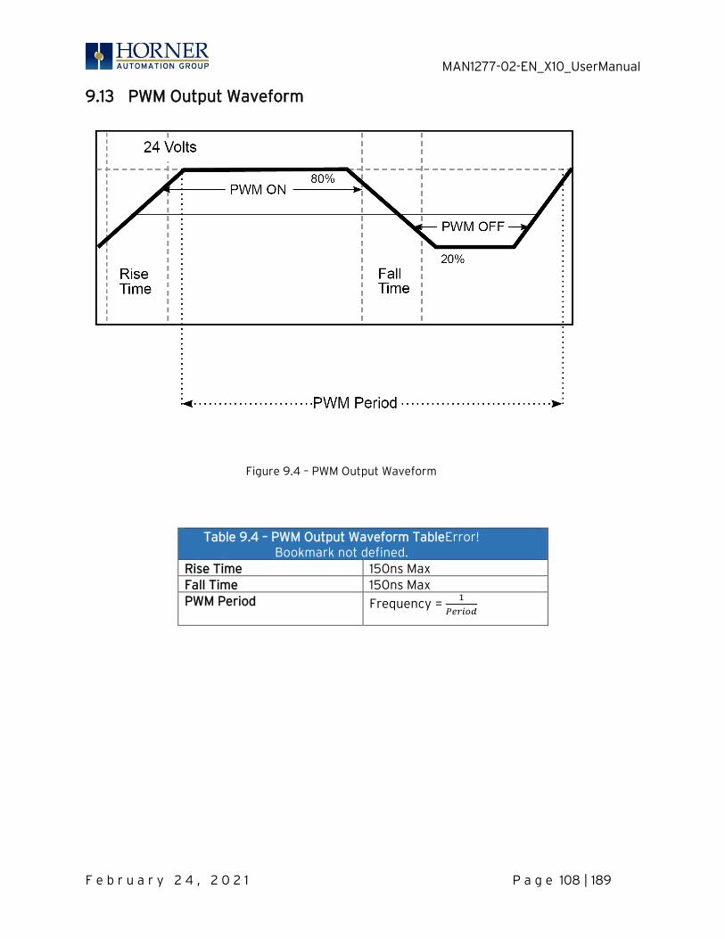
MAN1277-02-EN_X10_UserManual
F e b r u a r y 2 4 , 2 0 2 1 P a g e 108 | 189
9.13 PWM Output Waveform
Figure 9.4 – PWM Output Waveform
Table 9.4 – PWM Output Waveform TableError! Bookmark not defined.
Rise Time 150ns Max Fall Time 150ns Max PWM Period Frequency =
1
𝑃𝑒𝑟𝑖𝑜𝑑
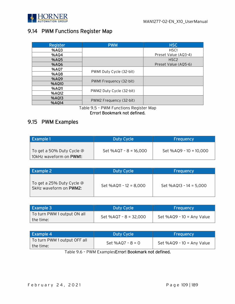
MAN1277-02-EN_X10_UserManual
F e b r u a r y 2 4 , 2 0 2 1 P a g e 109 | 189
9.14 PWM Functions Register Map
Register PWM HSC
%AQ3 HSC1 Preset Value (AQ3-4) %AQ4
%AQ5 HSC2 Preset Value (AQ5-6) %AQ6
%AQ7
PWM1 Duty Cycle (32-bit) %AQ8 %AQ9
PWM1 Frequency (32-bit) %AQ10 %AQ11
PWM2 Duty Cycle (32-bit) %AQ12 %AQ13
PWM2 Frequency (32-bit) %AQ14
Table 9.5 – PWM Functions Register Map Error! Bookmark not defined.
9.15 PWM Examples
Example 1 Duty Cycle Frequency
To get a 50% Duty Cycle @ 10kHz waveform on PWM1:
Set %AQ7 – 8 = 16,000 Set %AQ9 – 10 = 10,000
Example 2 Duty Cycle Frequency
To get a 25% Duty Cycle @ 5kHz waveform on PWM2:
Set %AQ11 – 12 = 8,000
Set %AQ13 – 14 = 5,000
Example 3 Duty Cycle Frequency
To turn PWM 1 output ON all the time:
Set %AQ7 – 8 = 32,000 Set %AQ9 – 10 = Any Value
Example 4 Duty Cycle Frequency
To turn PWM 1 output OFF all the time:
Set %AQ7 – 8 = 0 Set %AQ9 – 10 = Any Value
Table 9.6 – PWM ExamplesError! Bookmark not defined.

MAN1277-02-EN_X10_UserManual
F e b r u a r y 2 4 , 2 0 2 1 P a g e 110 | 189
CHAPTER 10: SERIAL COMMUNICATIONS
10.1 Overview
All X10 OCS models provide two serial ports, which are implemented with a single 8-position modular jack that is labeled MJ1/2. The MJ1 serial port is RS-232 while the MJ2 port is RS-485. MJ1 defaults to OCS programming by connecting it to the COM port of a PC running Cscape. In addition, both MJ1 and MJ2 can be used for application-specific communication, using a variety of standard data exchange protocols.
10.2 Port Descriptions
The MJ1 serial port contains a RS-232 interface with RTS/CTS handshaking.
The MJ2 serial port contains half-duplex RS-485 interface with no handshaking. The MJ2 RS-485 interface provides switchable termination and bias resistors internally. FERRITE CORE: Attach optional ferrite core with a minimum of two turns of serial cable.
10.3 Wiring—MJ1/MJ2 Serial Ports
Table 10.1—MJ1/MJ2 Serial PortsError! Bookmark not defined.
Pin MJ1 Pins MJ2 Pins Signal Direction Signal Direction
8 TXD OUT -- --
7 RXD IN -- --
6 0V Common 0V Common
5 +5VDC @ 60mA OUT +5VDC @ 60mA OUT
4 RTS OUT -- --
3 CTS IN -- --
2 -- -- RX- / TX- IN / OUT
1 -- -- RX+ / TX+ IN / OUT
MJ1: RS-232 w/Full Handshaking MJ2: RS-485 Half-Duplex

MAN1277-02-EN_X10_UserManual
F e b r u a r y 2 4 , 2 0 2 1 P a g e 111 | 189
10.4 RS-485 Termination and Biasing
Termination—Proper RS-485 termination minimizes reflections and improves reliability. The MJ2 serial port allows an internal termination resistor to be placed across pins 1 and 2 by software control. Only the two devices physically located at the endpoints of the RS485 network should be terminated. This termination is only in place when the X10 is powered on. This would typically only be an issue if the X10 is being used as a slave on the RS485 network. In that case, the electronic should not be used, but a physical external termination resistor should be used instead. Biasing—RS485 biasing passively asserts a line-idle state when no device is actively transmitting, which is useful for multi-drop RS485 networking. The MJ2 serial port allows internal bias resistor to be activated by software control, pulling pin 1 up to 3.3V and pulling pin 2 down to ground. NOTE: If biasing is used, it should be enabled in only one of the devices attached to the RS485 network. The “Set Serial Ports” option in the OCS System Menu can be used for termination and biasing. Also, an application graphics screen that writes to %SR can do the same thing. Biasing Details: • %SR152.3 enables RS485 Port Termination • %SR164.1 enables RS485 Port Biasing
10.5 Cscape Programming via Serial Port
MJ1 is the serial port available for programming. The connection is RS-232 and is compatible with the Horner programming cable kits HE-XCK or HE-XCPK. Unlike some other OCS models, the MJ2 port cannot be configured as a programming port. The Mini-B USB port is also available for programming.
The “Set Serial Ports” option in the OCS System Menu contains an entry for Default Programming Port (Dflt Pgm Port). However, the entry is fixed at MJ1-232. No OCS configuration is required to use either the MJ1 serial port or Mini-B USB port for programming.
NOTE: Only one Cscape software connection is allowed at a time.

MAN1277-02-EN_X10_UserManual
F e b r u a r y 2 4 , 2 0 2 1 P a g e 112 | 189
10.6 Ladder-Controlled Serial Communication
Using Serial Communication function blocks, both MJ1 and MJ2 support Generic, Modbus Master and Modbus Slave Protocols. In addition, external modems can be connected and accessed using Init, Dial and Answer Modem function blocks.
10.7 Configuration via Mini-B USB
NOTE: The unit must be connected via the mini-USB port to the PC or laptop. It is possible to load the program and monitor data via the Mini-B USB. To load via Mini-B USB, configure the communications port in Cscape as follows: Select Tools from the toolbar → Application Settings → Communications → USB button It is possible to download or upload and use the data monitoring functions once connected. NOTE: It is advisable to use an isolated USB cable between the PC or laptop and the X10 when third party devices are connected to the X10 to avoid damage to the PC or laptop and/or the X10.

MAN1277-02-EN_X10_UserManual
F e b r u a r y 2 4 , 2 0 2 1 P a g e 113 | 189
CHAPTER 11: CAN COMMUNICATIONS NOTE: For additional CAN information, refer to the CAN Networks manual (MAN0799) on the website. North America https://hornerautomation.com Europe www.hornerautomation.eu
11.1 Overview
The X10 OCS provides a CAN networking port, which is implemented with an 8-position RJ-45 modular jack. The CAN connector is red.
Figure 11.1 – CAN Connector
Error! Bookmark not defined.

MAN1277-02-EN_X10_UserManual
F e b r u a r y 2 4 , 2 0 2 1 P a g e 114 | 189
11.2 CAN Port Wiring
11.3 Cscape Programming via CAN
The CAN port supports CsCAN Programming Protocol. If a PC has a CAN interface installed (via PCI card or USB), and the PC CAN port is connected to the X10 CAN port, then Cscape can access the X10 for programming and monitoring.
In addition, the X10 supports single-point-programming of all X10 and other Horner controllers that are connected to a CAN network. If the PC COM port is connected to the X10 programming port, then the X10 can act as a pass-through gateway allowing Cscape to access all X10 and Horner controllers that are attached to the CAN network.
11.4 Ladder-Controlled CAN Communication
Using Put and Get Network Words function blocks, the CAN port can exchange digital and analog global data with other Horner controllers attached to the CAN network. In addition, Put and Get Network Heartbeat function blocks allow nodes on the CAN network to regularly announce their presence and to detect the presence (or absence) of other nodes on the network.
MAN1277-02-EN_X10_UserManual
F e b r u a r y 2 4 , 2 0 2 1 P a g e 115 | 189
11.5 Using CAN for I/O Expansion (Network I/O)
Connecting remote I/O to the X10 CAN port, allows the X10 I/O to be economically expanded and distributed. A variety of remote I/O modules is available for this purpose.
11.6 CAN and Termination and Bias
If there is a controller-to-controller communication on a network, and an X10 will be at either end, then it is recommended that onboard electronic termination NOT be used. Physical external resistors should be used instead. In this case, utilizing RJ45 to open-style connector will make termination easier.
NOTE: %SR152 enables CAN port termination.
NOTE: When powered down, the biasing and termination is no longer in effect.
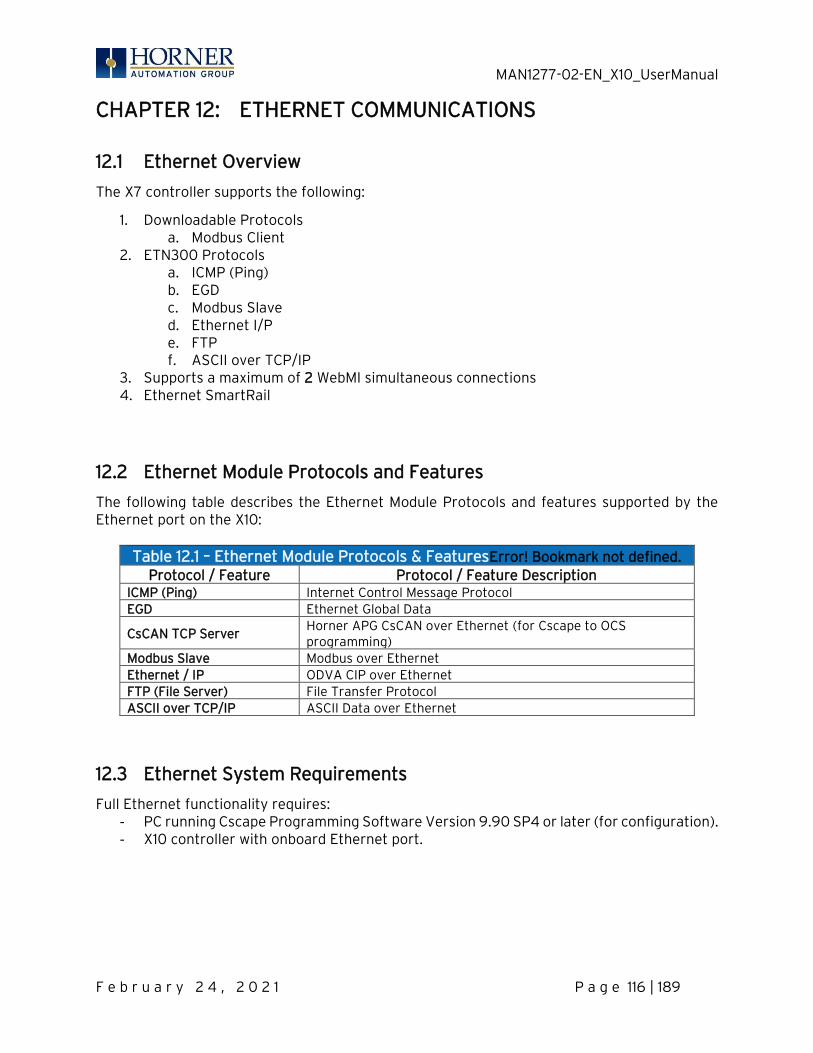
MAN1277-02-EN_X10_UserManual
F e b r u a r y 2 4 , 2 0 2 1 P a g e 116 | 189
CHAPTER 12: ETHERNET COMMUNICATIONS
12.1 Ethernet Overview
The X7 controller supports the following:
1. Downloadable Protocols a. Modbus Client
2. ETN300 Protocols a. ICMP (Ping) b. EGD c. Modbus Slave d. Ethernet I/P e. FTP f. ASCII over TCP/IP
3. Supports a maximum of 2 WebMI simultaneous connections 4. Ethernet SmartRail
12.2 Ethernet Module Protocols and Features
The following table describes the Ethernet Module Protocols and features supported by the Ethernet port on the X10:
Table 12.1 – Ethernet Module Protocols & FeaturesError! Bookmark not defined. Protocol / Feature Protocol / Feature Description
ICMP (Ping) Internet Control Message Protocol EGD Ethernet Global Data
CsCAN TCP Server Horner APG CsCAN over Ethernet (for Cscape to OCS programming)
Modbus Slave Modbus over Ethernet Ethernet / IP ODVA CIP over Ethernet FTP (File Server) File Transfer Protocol ASCII over TCP/IP ASCII Data over Ethernet
12.3 Ethernet System Requirements
Full Ethernet functionality requires: - PC running Cscape Programming Software Version 9.90 SP4 or later (for configuration). - X10 controller with onboard Ethernet port.
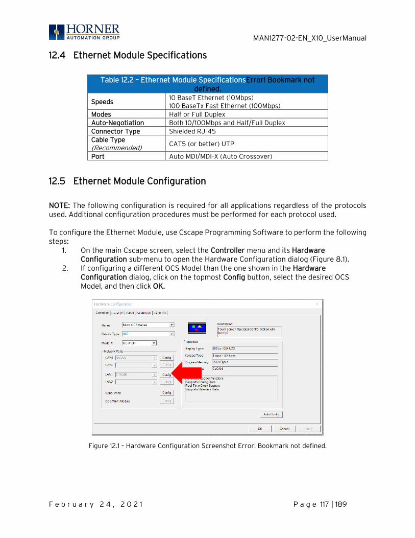
MAN1277-02-EN_X10_UserManual
F e b r u a r y 2 4 , 2 0 2 1 P a g e 117 | 189
12.4 Ethernet Module Specifications
Table 12.2 – Ethernet Module SpecificationsError! Bookmark not
defined.
Speeds 10 BaseT Ethernet (10Mbps) 100 BaseTx Fast Ethernet (100Mbps)
Modes Half or Full Duplex Auto-Negotiation Both 10/100Mbps and Half/Full Duplex Connector Type Shielded RJ-45 Cable Type (Recommended)
CAT5 (or better) UTP
Port Auto MDI/MDI-X (Auto Crossover)
12.5 Ethernet Module Configuration
NOTE: The following configuration is required for all applications regardless of the protocols used. Additional configuration procedures must be performed for each protocol used. To configure the Ethernet Module, use Cscape Programming Software to perform the following steps:
1. On the main Cscape screen, select the Controller menu and its Hardware Configuration sub-menu to open the Hardware Configuration dialog (Figure 8.1).
2. If configuring a different OCS Model than the one shown in the Hardware Configuration dialog, click on the topmost Config button, select the desired OCS Model, and then click OK.
Figure 12.1 – Hardware Configuration Screenshot Error! Bookmark not defined.
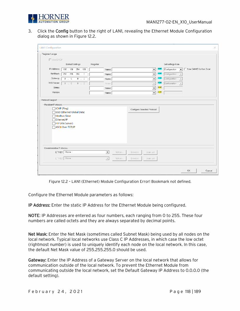
MAN1277-02-EN_X10_UserManual
F e b r u a r y 2 4 , 2 0 2 1 P a g e 118 | 189
3. Click the Config button to the right of LAN1, revealing the Ethernet Module Configuration dialog as shown in Figure 12.2.
Figure 12.2 – LAN1 (Ethernet) Module Configuration Error! Bookmark not defined.
Configure the Ethernet Module parameters as follows: IP Address: Enter the static IP Address for the Ethernet Module being configured. NOTE: IP Addresses are entered as four numbers, each ranging from 0 to 255. These four numbers are called octets and they are always separated by decimal points.
Net Mask: Enter the Net Mask (sometimes called Subnet Mask) being used by all nodes on the local network. Typical local networks use Class C IP Addresses, in which case the low octet (rightmost number) is used to uniquely identify each node on the local network. In this case, the default Net Mask value of 255.255.255.0 should be used. Gateway: Enter the IP Address of a Gateway Server on the local network that allows for communication outside of the local network. To prevent the Ethernet Module from communicating outside the local network, set the Default Gateway IP Address to 0.0.0.0 (the default setting).

MAN1277-02-EN_X10_UserManual
F e b r u a r y 2 4 , 2 0 2 1 P a g e 119 | 189
Status Register: Enter an OCS Register reference (such as %R100) to indicate which 16-bit OCS register will have the Ethernet Status word written to it. Table 7.3 shows how this register value is formatted and explains the meaning of each bit in the Status Word.
Table 12.3 - Ethernet Status Word Register FormatError! Bookmark not defined. High Byte Low Byte
Bit 16
Bit 15
Bit 14
Bit 13
Bit 12
Bit 11
Bit 10
Bit 9
Bit 8
Bit 7
Bit 6
Bit 5
Bit 4
Bit 3
Bit 2
Bit 1
0 0 Dup Spd 0 Rx Tx Link TCP Connections
Status Bit(s) Status Indication Status Values
Minimum Maximum
0 Reserved Always 0
Dup Link Duplex (Auto-Negotiated) 0 = Half Duplex
1 = Full Duplex
Spd Link Speed (Auto-Negotiated) 0 = 10MHz 1 = 100MHz Rx Receive State 0 = Inactive 1 = Active Tx Transmit State 0 = Inactive 1 = Active
Link Link State 0 = Down 1 = Up
TCP Connections Total Number of Active TCP
Connections (CsCAN, SRTP, Modbus, EIP, FTP, HTTP)
0 40
Version Register: Enter an OCS Register reference (such as %R101) to indicate which 16-bit OCS register will have the Ethernet Firmware Version written to it. The value stored in the Version Register is (Ethernet Firmware Version * 100). For example, for Ethernet Firmware Version 4.30, the Version register will contain 430.
Get Settings From: “Get settings from” allows the programmer to either configure the IP Address, Net Mask, or Gateway for two functions: Configuration or Register. 1. Configuration – The configuration for the IP Address, Net Mask, or the Gateway will be assigned using the value in the Default Settings in this window. 2. Register – The configuration for the IP Address, Net Mask, or the Gateway will be assigned using the values in the registers assigned.
MAN1277-02-EN_X10_UserManual
F e b r u a r y 2 4 , 2 0 2 1 P a g e 120 | 189
12.6 Ethernet Configuration – IP Parameters
For primary operation, the IP address, Net Mask, and Gateway should be set in the LAN config of the Cscape Hardware Configuration. There are options to get IP parameters from the LAN Config or to get parameters from registers. It is possible to set the Ethernet IP parameters from the OCS System Menu, but only as a temporary measure. The following points on IP parameter configuration should be considered.
• IP Parameters in Non-Volatile RAM: The IP parameters of the Cscape LAN Config are written to non-volatile RAM on power down. IP parameter settings made in the System Menu are not written to non-volatile RAM. Any IP parameters settings made in the system menu will be lost after cycling power to the unit. It will revert back to the last downloaded Cscape LAN Config that was loaded into non-volatile RAM at power down.
• “Cscape LAN Config”/ “Get Settings from” Configuration: When ‘Get settings from’ is set to Configuration, the IP parameters specified under ‘Default Settings’ is used after downloading to the controller. The IP parameters are represented in System Menu / Set Networks and can be edited. However, any edits made from System Menu / Set Networks is not retained through a power cycle. After power cycle, the unit reverts to the last downloaded Cscape LAN Config that was loaded into non-volatile RAM at power down.
• “Cscape LAN Config” / “Get Settings from” Register: When ‘Get settings from’ is set to Register, the IP parameters are retrieved from the OCS registers assigned in LAN Config. Configured registers must be populated with the desired IP parameters. The IP parameters are represented in System Menu / Set Networks. The IP parameters cannot be edited from System Menu / Set Networks while the unit is in run mode. The IP parameters always follow the values in the registers unless the OCS unit is placed in idle mode. Then the IP parameters can be edited in System Menu / Set Networks. When the OCS is placed back into run mode, it reverts to the registers for IP parameters.
12.7 Ethernet Module Protocol Configuration
The Protocol Support area contains a list of all the protocols supported by the platform being configured. To activate a protocol, check its checkbox. For protocols that require additional configuration, click on a listed protocol to select it and then click the Configure Selected Protocol button. This will open a new dialog with configuration options for the selected protocol. For detailed information on individual protocol configuration refer to the latest version of the ETN 300 Manual SUP0740.

MAN1277-02-EN_X10_UserManual
F e b r u a r y 2 4 , 2 0 2 1 P a g e 121 | 189
CHAPTER 13: DOWNLOADABLE COMMUNICATION PROTOCOLS
13.1 Overview
Through loadable protocol device drivers, certain models of the OCS family can provide the ability to exchange data with remote devices such as variable-frequency drives, PLCs, and remote I/O devices. This feature greatly expands the OCS ’s control capability with negligible effect on the OCS ’s ladder scan time. Remote devices that communicate serially must do so under certain rules of data transfer known as a protocol. Many device manufactures have created their own protocol for communications with their device. For an OCS to communicate with a specific device, it must be loaded with the corresponding serial communications protocol device driver that supports that protocol. A limited number of protocol device drivers are packaged with the Cscape distribution; however, as more are developed, they will be made available as add-on packages. A device driver is typically distributed as a Windows module, which contains the Configuration Menus, Help Files and the Target Executable Driver Code. When updating device drivers, an install routine loads the device driver to the Cscape directory structure and makes that driver available to Cscape applications. Once installed, the protocol device driver can be included as part of a Cscape application by selecting it from a list of installed protocol device drivers and attaching it to the desired serial port (Program > Protocol Config menu). Only one protocol device driver can be associated with a serial port, though some OCS models support multiple protocols on a single Ethernet port. Once the protocol is selected for a specific port, that port must be configured to match the bit transfer size and rate of the target device(s). This is configured under the Network Config menu, which contains port specific information such as the basic serial port parameters (i.e. baud rate, stop bits parity, retries, etc.). In addition to the serial port parameters, this menu also contains the transaction scan update control configuration and any network level protocol specific configuration. Once the network is configured, each device on the serial communications network must be configured. For some communications (i.e. RS232), the network can be limited to one device. The devices are configured under the Device Config menu, which contains an arbitrary device name, the device ID and optionally an OCS status register that contains any device fault information. Once each device(s) is configured, a Scan List of entries must be created which defines the transfer of data between a local (OCS) register(s) and a remote device register(s). These entries are created under the Data Mapping menu, which contains an OCS register, a target device ID, a target device register address, the number of registers to transfer, and update type.
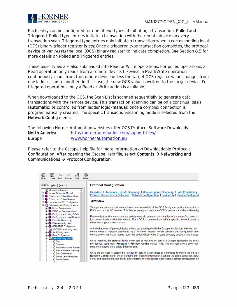
MAN1277-02-EN_X10_UserManual
F e b r u a r y 2 4 , 2 0 2 1 P a g e 122 | 189
Each entry can be configured for one of two types of initiating a transaction: Polled and Triggered. Polled type entries initiate a transaction with the remote device on every transaction scan. Triggered type entries only initiate a transaction when a corresponding local (OCS) binary trigger register is set. Once a triggered type transaction completes, the protocol device driver resets the local (OCS) binary register to indicate completion. See Section 8.5 for more details on Polled and Triggered entries. These basic types are also subdivided into Read or Write operations. For polled operations, a Read operation only reads from a remote device. Likewise, a Read/Write operation continuously reads from the remote device unless the target OCS register value changes from one ladder scan to another. In this case, the new OCS value is written to the target device. For triggered operations, only a Read or Write action is available. When downloaded to the OCS, the Scan List is scanned sequentially to generate data transactions with the remote device. This transaction scanning can be on a continual basis (automatic) or controlled from ladder logic (manual) once a complex connection is programmatically created. The specific transaction-scanning mode is selected from the Network Config menu. The following Horner Automation websites offer OCS Protocol Software Downloads. North America http://hornerautomation.com/support-files/ Europe www.hornerautomation.eu
Please refer to the Cscape Help file for more information on Downloadable Protocols Configuration. After opening the Cscape Help file, select Contents → Networking and Communications → Protocol Configuration.
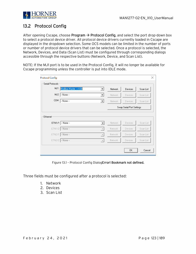
MAN1277-02-EN_X10_UserManual
F e b r u a r y 2 4 , 2 0 2 1 P a g e 123 | 189
13.2 Protocol Config
After opening Cscape, choose Program → Protocol Config, and select the port drop-down box to select a protocol device driver. All protocol device drivers currently loaded in Cscape are displayed in the dropdown selection. Some OCS models can be limited in the number of ports or number of protocol device drivers that can be selected. Once a protocol is selected, the Network, Devices, and Data (Scan List) must be configured through corresponding dialogs accessible through the respective buttons (Network, Device, and Scan List). NOTE: If the MJ1 port is to be used in the Protocol Config, it will no longer be available for Cscape programming unless the controller is put into IDLE mode.
Figure 13.1 – Protocol Config DialogError! Bookmark not defined.
Three fields must be configured after a protocol is selected:
1. Network 2. Devices 3. Scan List
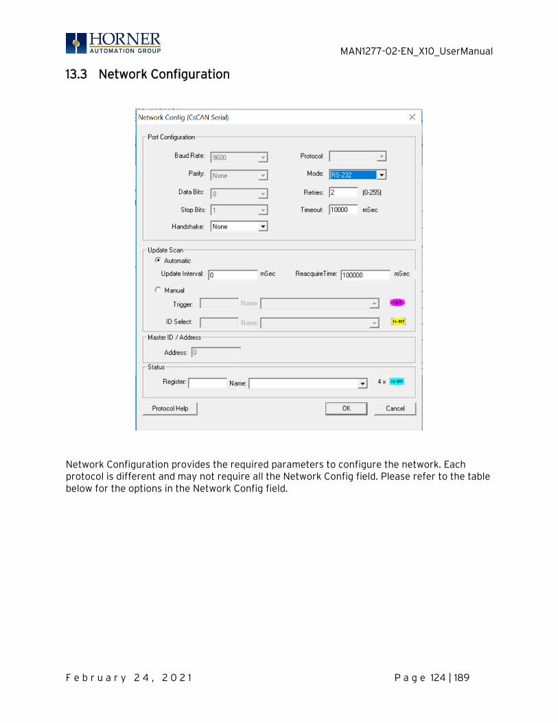
MAN1277-02-EN_X10_UserManual
F e b r u a r y 2 4 , 2 0 2 1 P a g e 124 | 189
13.3 Network Configuration
Network Configuration provides the required parameters to configure the network. Each protocol is different and may not require all the Network Config field. Please refer to the table below for the options in the Network Config field.
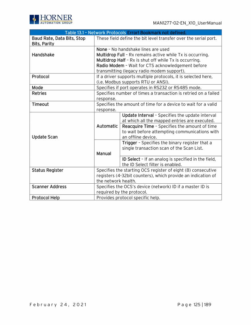
MAN1277-02-EN_X10_UserManual
F e b r u a r y 2 4 , 2 0 2 1 P a g e 125 | 189
Table 13.1 – Network Protocols Error! Bookmark not defined. Baud Rate, Data Bits, Stop Bits, Parity
These field define the bit level transfer over the serial port.
Handshake
None – No handshake lines are used Multidrop Full – Rx remains active while Tx is occurring. Multidrop Half – Rx is shut off while Tx is occurring. Radio Modem – Wait for CTS acknowledgement before transmitting (legacy radio modem support).
Protocol If a driver supports multiple protocols, it is selected here, (i.e. Modbus supports RTU or ANSI).
Mode Specifies if port operates in RS232 or RS485 mode. Retries Specifies number of times a transaction is retried on a failed
response. Timeout Specifies the amount of time for a device to wait for a valid
response. Update Scan
Automatic
Update Interval – Specifies the update interval at which all the mapped entries are executed. Reacquire Time – Specifies the amount of time to wait before attempting communications with an offline device.
Manual
Trigger – Specifies the binary register that a single transaction scan of the Scan List. ID Select – If an analog is specified in the field, the ID Select filter is enabled.
Status Register Specifies the starting OCS register of eight (8) consecutive registers (4-32bit counters), which provide an indication of the network health.
Scanner Address Specifies the OCS’s device (network) ID if a master ID is required by the protocol.
Protocol Help Provides protocol specific help.
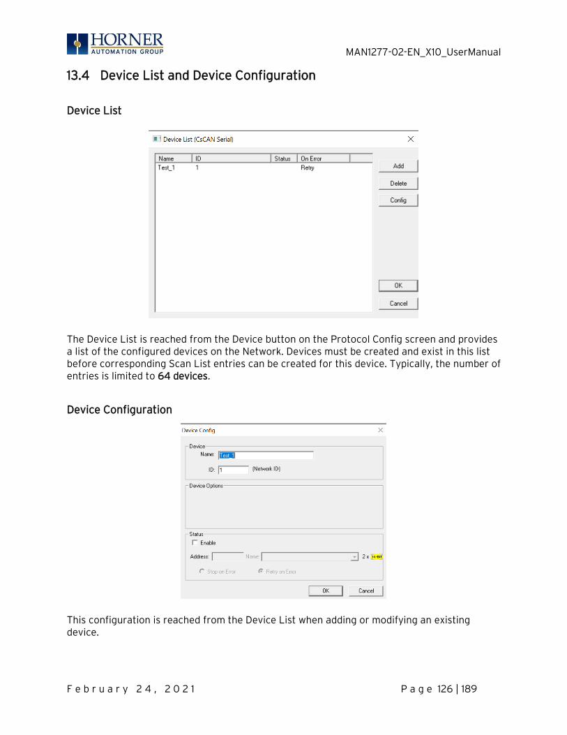
MAN1277-02-EN_X10_UserManual
F e b r u a r y 2 4 , 2 0 2 1 P a g e 126 | 189
13.4 Device List and Device Configuration
Device List
The Device List is reached from the Device button on the Protocol Config screen and provides a list of the configured devices on the Network. Devices must be created and exist in this list before corresponding Scan List entries can be created for this device. Typically, the number of entries is limited to 64 devices.
Device Configuration
This configuration is reached from the Device List when adding or modifying an existing device.
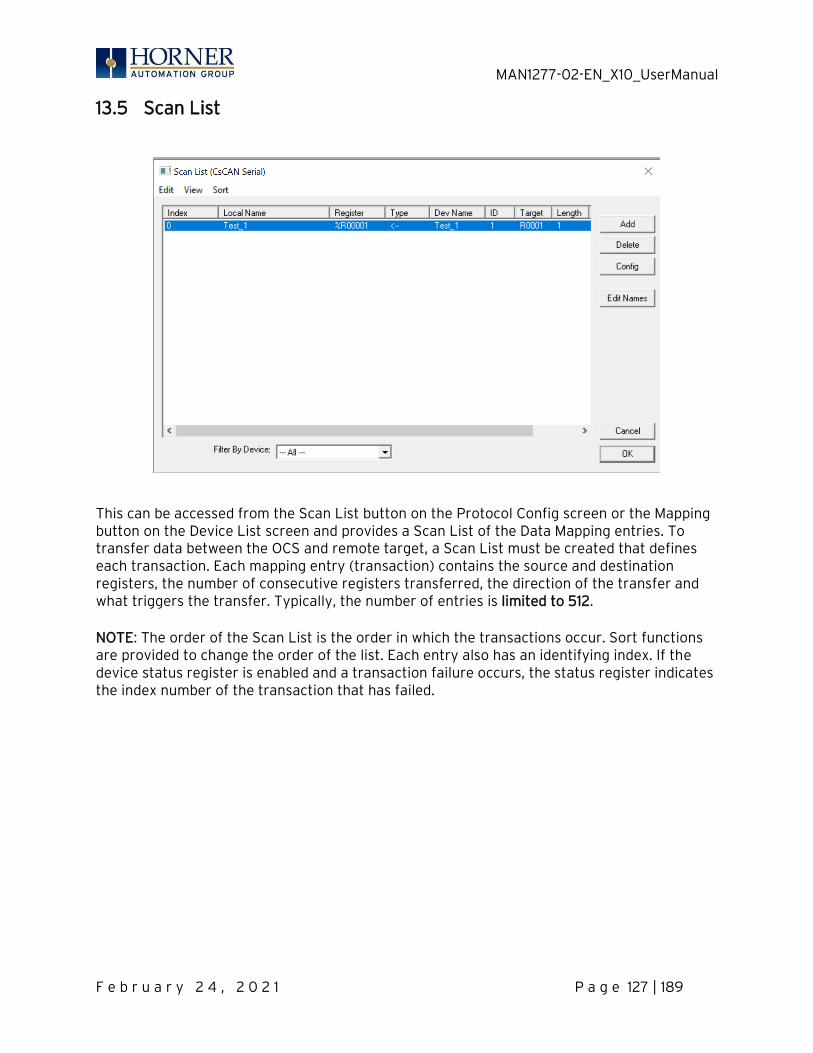
MAN1277-02-EN_X10_UserManual
F e b r u a r y 2 4 , 2 0 2 1 P a g e 127 | 189
13.5 Scan List
This can be accessed from the Scan List button on the Protocol Config screen or the Mapping button on the Device List screen and provides a Scan List of the Data Mapping entries. To transfer data between the OCS and remote target, a Scan List must be created that defines each transaction. Each mapping entry (transaction) contains the source and destination registers, the number of consecutive registers transferred, the direction of the transfer and what triggers the transfer. Typically, the number of entries is limited to 512. NOTE: The order of the Scan List is the order in which the transactions occur. Sort functions are provided to change the order of the list. Each entry also has an identifying index. If the device status register is enabled and a transaction failure occurs, the status register indicates the index number of the transaction that has failed.
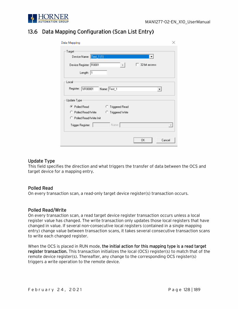
MAN1277-02-EN_X10_UserManual
F e b r u a r y 2 4 , 2 0 2 1 P a g e 128 | 189
13.6 Data Mapping Configuration (Scan List Entry)
Update Type This field specifies the direction and what triggers the transfer of data between the OCS and target device for a mapping entry. Polled Read On every transaction scan, a read-only target device register(s) transaction occurs. Polled Read/Write On every transaction scan, a read target device register transaction occurs unless a local register value has changed. The write transaction only updates those local registers that have changed in value. If several non-consecutive local registers (contained in a single mapping entry) change value between transaction scans, it takes several consecutive transaction scans to write each changed register. When the OCS is placed in RUN mode, the initial action for this mapping type is a read target register transaction. This transaction initializes the local (OCS) register(s) to match that of the remote device register(s). Thereafter, any change to the corresponding OCS register(s) triggers a write operation to the remote device.

MAN1277-02-EN_X10_UserManual
F e b r u a r y 2 4 , 2 0 2 1 P a g e 129 | 189
Polled Read/Write/Init On every transaction scan, a read target device register transaction occurs unless a local register value has changed. The write transaction only updates those local registers that have changed in value. If several non-consecutive local registers (contained in a single mapping entry) change value between transaction scans, it takes several consecutive scans to write each changed register. When the OCS is placed in RUN mode, the initial action for this mapping type is a write target register transaction. This transaction initializes the target device register(s) to match that of the local (OCS) register(s). Thereafter, any change to the corresponding OCS register(s) triggers a write operation to the remote device. The initial write transaction does not occur until after the first logic scan of the OCS. This allows registers to be initialized locally before Writing to the target device register(s). Triggered Read A read transaction is triggered by a high level on a separately designated OCS (binary) trigger register. Once the read transaction is complete (or the device is offline), the OCS trigger register is cleared by the OCS. This update type can be used for occasion data accesses such as retrieving trend data. NOTE: This operation increases the associated transaction scan time and can cause the Update Interval Exceeded Counter to increment on a tightly adjusted update interval. Triggered Write A write transaction is triggered by a high level on a separately designated OCS (binary) trigger register. Once the write transaction is complete (or the device is offline), the OCS trigger register is cleared by OCS. This function can be used for occasion data accesses such as sending recipe data. NOTE: This operation increases the associated transaction scan time and can cause the Update Interval Time Exceeded Counter to increment on a tightly adjusted update interval.
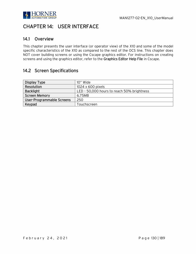
MAN1277-02-EN_X10_UserManual
F e b r u a r y 2 4 , 2 0 2 1 P a g e 130 | 189
CHAPTER 14: USER INTERFACE
14.1 Overview
This chapter presents the user interface (or operator view) of the X10 and some of the model specific characteristics of the X10 as compared to the rest of the OCS line. This chapter does NOT cover building screens or using the Cscape graphics editor. For instructions on creating screens and using the graphics editor, refer to the Graphics Editor Help File in Cscape.
14.2 Screen Specifications
Display Type 10” Wide Resolution 1024 x 600 pixels Backlight LED – 50,000 hours to reach 50% brightness Screen Memory 6.75MB User-Programmable Screens 250 Keypad Touchscreen

MAN1277-02-EN_X10_UserManual
F e b r u a r y 2 4 , 2 0 2 1 P a g e 131 | 189
14.3 Displaying and Entering Data
Figure 14.1 – Example ScreenError! Bookmark not defined.
Multiple objects are provided for displaying data such as virtual panel lights, push buttons, numeric value displays, bar graphs, meters, graphs, and animated bitmaps. On the X10, these graphical objects (through ladder manipulation of attribute bits) can change color, flash, or change visibility to attract operator attention. On objects that accept user input, the input is provided by touching the object or alternately changing an OCS register (i.e. Function Key Registers). Objects that allow input generally have a raised 3D appearance. An exception is the binary type objects, such as buttons, which are shown in a depressed 3D appearance when in the ON state. Objects that normally accept touch input may be disabled through program control (through ladder manipulation of an attribute bit). If an object is disabled, the object’s representation changes to a 2D appearance. On objects that represent non-discrete information, more action may be required beyond that of simply touching the object. For example, the slider object requires the operator to touch and slide the control in the direction desired. Alternately, alpha-numeric entry objects invoke a pop-up alpha-numeric keypad for additional user input. The alpha-numeric keypad is discussed below. NOTE: If the numeric entry object displays >>>>>>>, the value is too big to display in the field or is above the maximum for an editable field. Likewise, if the numeric entry object displays <<<<<<< in a numeric field, the value is too small to display or is below the minimum for an editable field.
MAN1277-02-EN_X10_UserManual
F e b r u a r y 2 4 , 2 0 2 1 P a g e 132 | 189
14.4 Numeric keypad
To allow entry of a specific number, several of the input objects invoke a pop-up numeric keypad when the object is touched. An example of the numeric keypad invoked from a numeric input object is shown in Figure 12.2. Once invoked, the operator may touch the appropriate keys to enter a specific value. When entering a value, the numeric keypad is in one of two modes [new-value or edit-value]. New-Value Mode Generally, when the numeric keypad is first invoked, it is placed in new-value mode. Initially, the numeric keypad displays the current value with all the digits being highlighted. Once the first digit is entered, the current value is erased from the display and the new digit is placed in the first location. Thereafter, no digits are highlighted, and new digits are added to the rightmost position while the other digits are shifted left. Edit-Value Mode Edit-value mode may be entered from the initial new-value mode by pressing either the left or right arrow key before any digit key is pressed. The result will be a single character highlighted. The user may then either touch a key to change the digit at the selected position or the up and down arrows may be used to add or subtract (respectively) from the selected digit. The user may then use the left or right arrow keys to select a new position. Once the desired value is entered, pressing the Enter key moves that value into the object (and the corresponding OCS register) and the alpha-numeric keypad disappears. Alternately, pressing the ESC key any time before the Enter key cancels the operation, leaves the objects current value unchanged, and the alpha-numeric keypad disappears. NOTE: Each numeric entry object has a configured minimum and maximum value. If the operator enters a value outside of the configured range, the new value is ignored when Enter is pressed and the current object value is NOT changed. Since the alpha-numeric keypad services several different graphical objects, certain keys on the alpha-numeric keypad may be disabled (grayed) when the keypad is invoked for certain objects. The following describes the alpha-numeric keypad variation based on object. Numeric Object When editing a numeric value, the [+/-] or the [.] key are disabled (grayed) if the object is NOT configured for floating-point value or a signed value. Password Object When editing a password value, the arrow keys, [+/-], and the [.] keys are disabled. Additionally, overwrite mode is disabled. When entering digits, the pop-up keypad hides the value by displaying ‘*’ alternately for each digit.
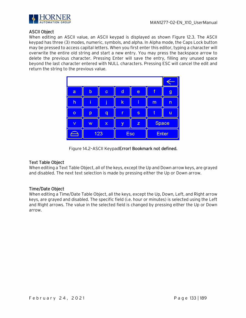
MAN1277-02-EN_X10_UserManual
F e b r u a r y 2 4 , 2 0 2 1 P a g e 133 | 189
ASCII Object When editing an ASCII value, an ASCII keypad is displayed as shown Figure 12.3. The ASCII keypad has three (3) modes, numeric, symbols, and alpha. In Alpha mode, the Caps Lock button may be pressed to access capital letters. When you first enter this editor, typing a character will overwrite the entire old string and start a new entry. You may press the backspace arrow to delete the previous character. Pressing Enter will save the entry, filling any unused space beyond the last character entered with NULL characters. Pressing ESC will cancel the edit and return the string to the previous value.
Figure 14.2–ASCII KeypadError! Bookmark not defined.
Text Table Object When editing a Text Table Object, all of the keys, except the Up and Down arrow keys, are grayed and disabled. The next text selection is made by pressing either the Up or Down arrow. Time/Date Object When editing a Time/Date Table Object, all the keys, except the Up, Down, Left, and Right arrow keys, are grayed and disabled. The specific field (i.e. hour or minutes) is selected using the Left and Right arrows. The value in the selected field is changed by pressing either the Up or Down arrow.
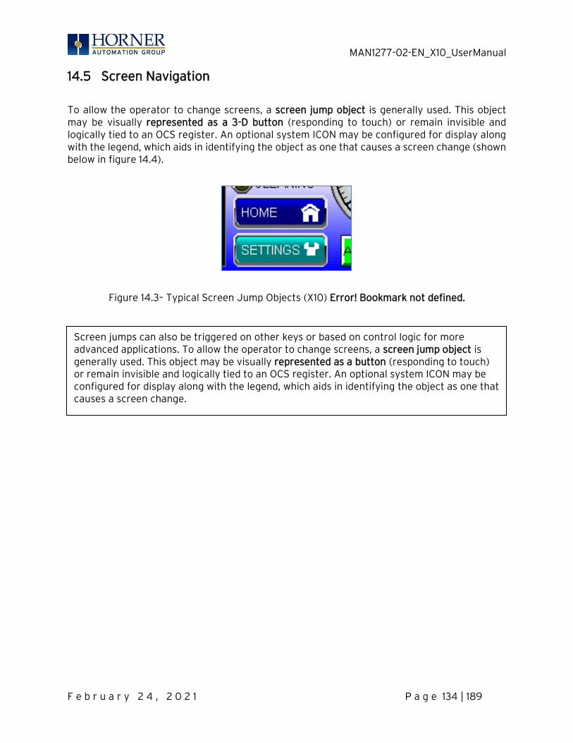
MAN1277-02-EN_X10_UserManual
F e b r u a r y 2 4 , 2 0 2 1 P a g e 134 | 189
14.5 Screen Navigation
To allow the operator to change screens, a screen jump object is generally used. This object may be visually represented as a 3-D button (responding to touch) or remain invisible and logically tied to an OCS register. An optional system ICON may be configured for display along with the legend, which aids in identifying the object as one that causes a screen change (shown below in figure 14.4).
Figure 14.3– Typical Screen Jump Objects (X10) Error! Bookmark not defined.
Screen jumps can also be triggered on other keys or based on control logic for more advanced applications. To allow the operator to change screens, a screen jump object is generally used. This object may be visually represented as a button (responding to touch) or remain invisible and logically tied to an OCS register. An optional system ICON may be configured for display along with the legend, which aids in identifying the object as one that causes a screen change.
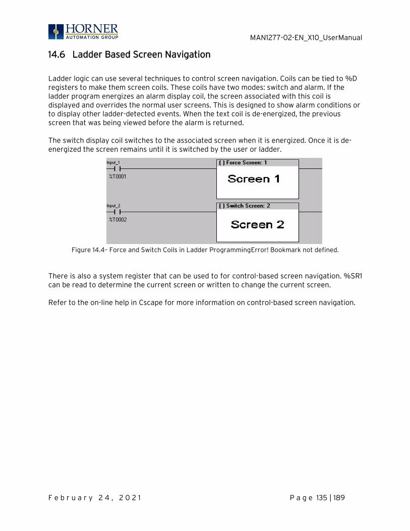
MAN1277-02-EN_X10_UserManual
F e b r u a r y 2 4 , 2 0 2 1 P a g e 135 | 189
14.6 Ladder Based Screen Navigation
Ladder logic can use several techniques to control screen navigation. Coils can be tied to %D registers to make them screen coils. These coils have two modes: switch and alarm. If the ladder program energizes an alarm display coil, the screen associated with this coil is displayed and overrides the normal user screens. This is designed to show alarm conditions or to display other ladder-detected events. When the text coil is de-energized, the previous screen that was being viewed before the alarm is returned. The switch display coil switches to the associated screen when it is energized. Once it is de-energized the screen remains until it is switched by the user or ladder.
Figure 14.4– Force and Switch Coils in Ladder ProgrammingError! Bookmark not defined.
There is also a system register that can be used to for control-based screen navigation. %SR1 can be read to determine the current screen or written to change the current screen. Refer to the on-line help in Cscape for more information on control-based screen navigation.

MAN1277-02-EN_X10_UserManual
F e b r u a r y 2 4 , 2 0 2 1 P a g e 136 | 189
14.7 Touch (Slip) Sensitivity
Touch slip sensitivity is preset to meet most applications; however, adjustment is available to reduce the sensitivity for touch release. That is, once a graphical object (button) is touched and held by a finger, the default touch slip sensitivity allows for a slight slip of the finger on the graphical object before the X10 assumes touch been released (equates to approximately a quarter inch of movement with a stylus). In some applications (such as jog buttons) where the operator is pushing a button for a period of time, the amount of slip while holding a button pressed may exceed the default sensitivity. To increase the amount of tolerable slip and prevent false releases of the button, the X10 allows adjustment of the allowable slide up to 5x the default value. To enable the touch (slip) sensitivity, first an OCS data register must be allocated through the Graphics Editor Configuration menu for Display Settings. Once a Touch Sensitivity register is assigned, that register may be modified [range = 1(Low) to 5 (High)] to the desired slide amount. If a value outside the valid range is entered in the touch sensitivity register, it is ignored, and the last valid value is used.
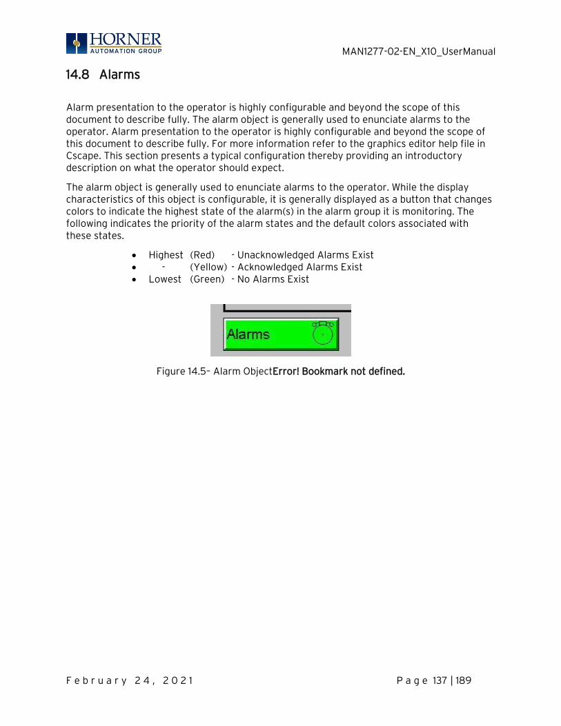
MAN1277-02-EN_X10_UserManual
F e b r u a r y 2 4 , 2 0 2 1 P a g e 137 | 189
14.8 Alarms
Alarm presentation to the operator is highly configurable and beyond the scope of this document to describe fully. The alarm object is generally used to enunciate alarms to the operator. Alarm presentation to the operator is highly configurable and beyond the scope of this document to describe fully. For more information refer to the graphics editor help file in Cscape. This section presents a typical configuration thereby providing an introductory description on what the operator should expect.
The alarm object is generally used to enunciate alarms to the operator. While the display characteristics of this object is configurable, it is generally displayed as a button that changes colors to indicate the highest state of the alarm(s) in the alarm group it is monitoring. The following indicates the priority of the alarm states and the default colors associated with these states.
• Highest (Red) - Unacknowledged Alarms Exist • - (Yellow) - Acknowledged Alarms Exist • Lowest (Green) - No Alarms Exist
Figure 14.5– Alarm ObjectError! Bookmark not defined.
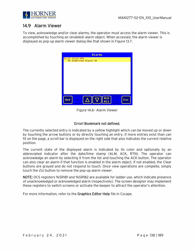
MAN1277-02-EN_X10_UserManual
F e b r u a r y 2 4 , 2 0 2 1 P a g e 138 | 189
14.9 Alarm Viewer
To view, acknowledge and/or clear alarms, the operator must access the alarm viewer. This is accomplished by touching an (enabled) alarm object. When accessed, the alarm viewer is displayed as pop-up alarm viewer dialog like that shown in Figure 13.7.
Figure 14.6– Alarm Viewer
Error! Bookmark not defined.
The currently selected entry is indicated by a yellow highlight which can be moved up or down by touching the arrow buttons or by directly touching an entry. If more entries exist than can fit on the page, a scroll bar is displayed on the right side that also indicates the current relative position.
The current state of the displayed alarm is indicated by its color and optionally by an abbreviated indicator after the date/time stamp (ALM, ACK, RTN). The operator can acknowledge an alarm by selecting it from the list and touching the ACK button. The operator can also clear an alarm if that function is enabled in the alarm object. If not enabled, the Clear buttons are grayed and do not respond to touch. Once view operations are complete, simply touch the Esc button to remove the pop-up alarm viewer.
NOTE: OCS registers %SR181 and %SR182 are available for ladder use, which indicate presence of unacknowledged or acknowledged alarm (respectively). The screen designer may implement these registers to switch screens or activate the beeper to attract the operator’s attention. For more information, refer to the Graphics Editor Help file in Cscape.
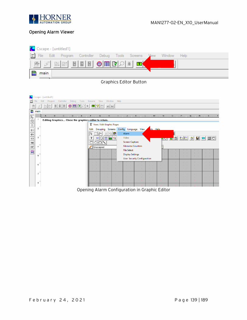
MAN1277-02-EN_X10_UserManual
F e b r u a r y 2 4 , 2 0 2 1 P a g e 139 | 189
Opening Alarm Viewer
Graphics Editor Button
Opening Alarm Configuration in Graphic Editor
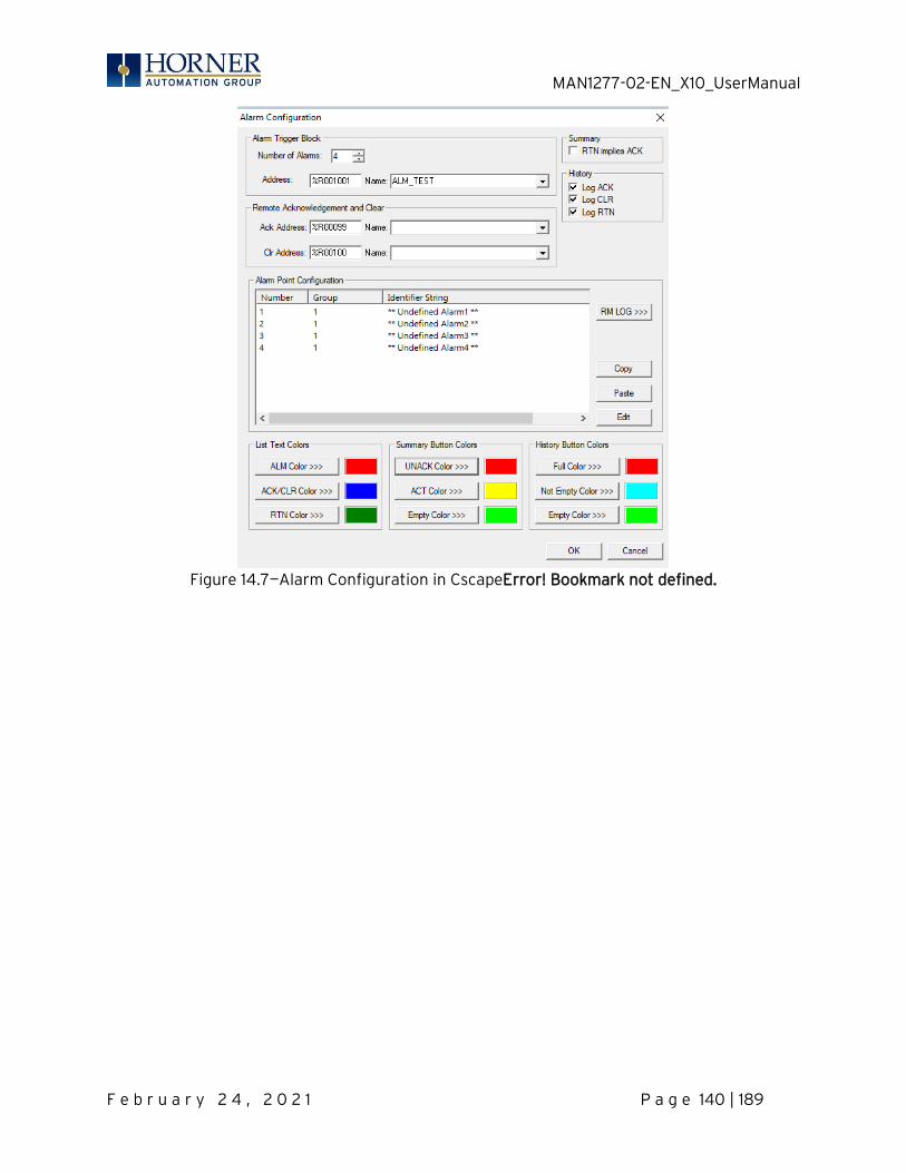
MAN1277-02-EN_X10_UserManual
F e b r u a r y 2 4 , 2 0 2 1 P a g e 140 | 189
Figure 14.7—Alarm Configuration in CscapeError! Bookmark not defined.
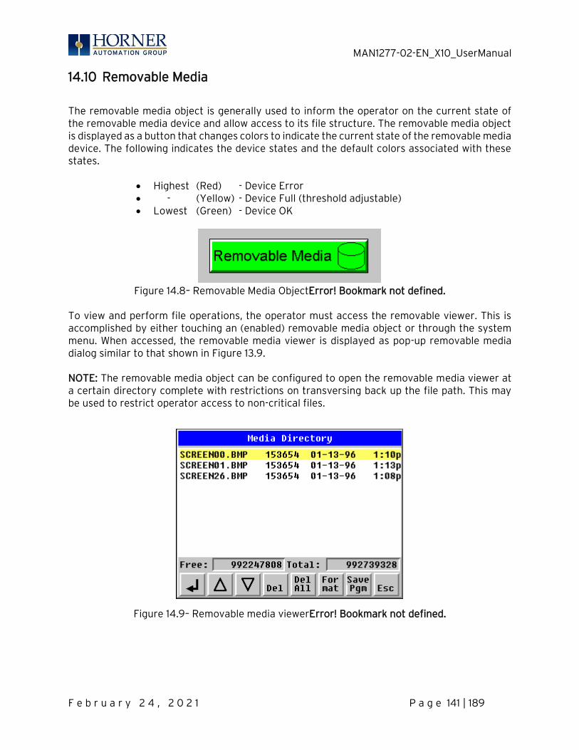
MAN1277-02-EN_X10_UserManual
F e b r u a r y 2 4 , 2 0 2 1 P a g e 141 | 189
14.10 Removable Media
The removable media object is generally used to inform the operator on the current state of the removable media device and allow access to its file structure. The removable media object is displayed as a button that changes colors to indicate the current state of the removable media device. The following indicates the device states and the default colors associated with these states.
• Highest (Red) - Device Error • - (Yellow) - Device Full (threshold adjustable) • Lowest (Green) - Device OK
Figure 14.8– Removable Media ObjectError! Bookmark not defined.
To view and perform file operations, the operator must access the removable viewer. This is accomplished by either touching an (enabled) removable media object or through the system menu. When accessed, the removable media viewer is displayed as pop-up removable media dialog similar to that shown in Figure 13.9. NOTE: The removable media object can be configured to open the removable media viewer at a certain directory complete with restrictions on transversing back up the file path. This may be used to restrict operator access to non-critical files.
Figure 14.9– Removable media viewerError! Bookmark not defined.
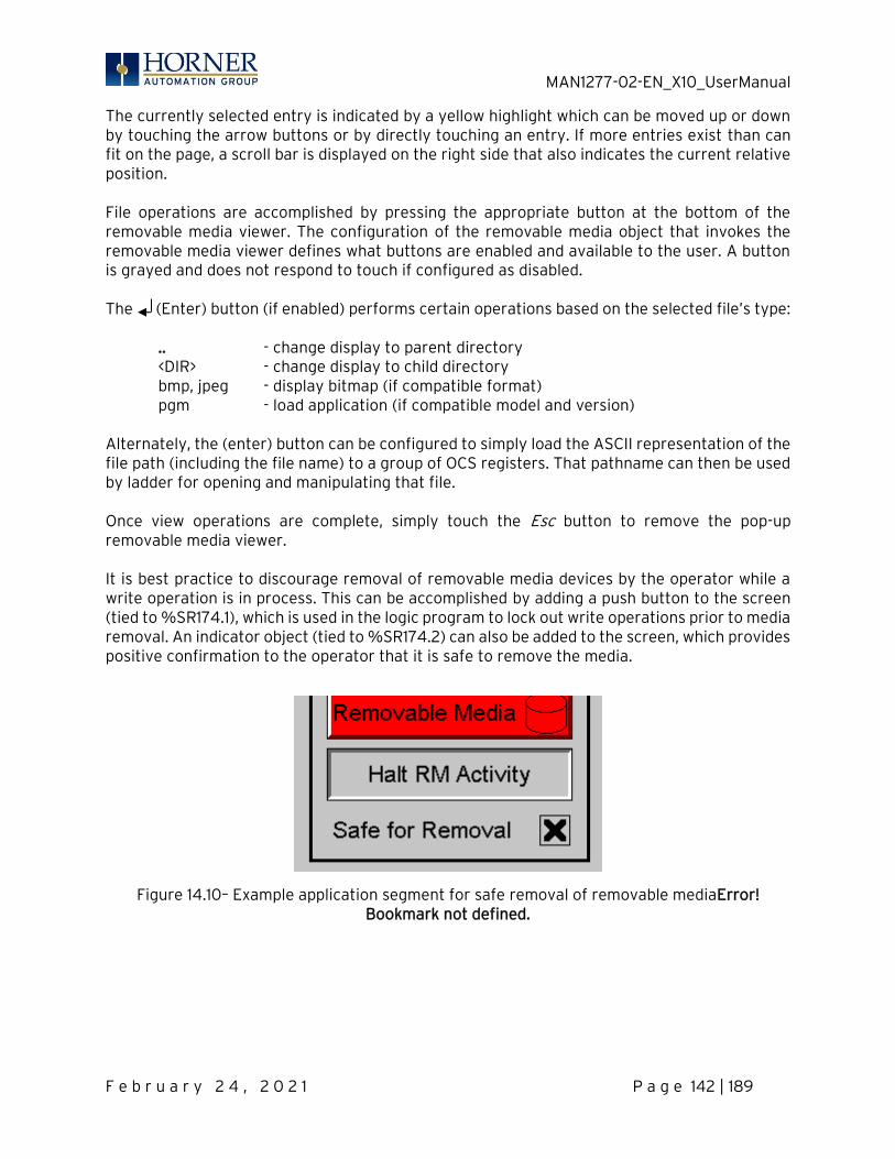
MAN1277-02-EN_X10_UserManual
F e b r u a r y 2 4 , 2 0 2 1 P a g e 142 | 189
The currently selected entry is indicated by a yellow highlight which can be moved up or down by touching the arrow buttons or by directly touching an entry. If more entries exist than can fit on the page, a scroll bar is displayed on the right side that also indicates the current relative position. File operations are accomplished by pressing the appropriate button at the bottom of the removable media viewer. The configuration of the removable media object that invokes the removable media viewer defines what buttons are enabled and available to the user. A button is grayed and does not respond to touch if configured as disabled. The (Enter) button (if enabled) performs certain operations based on the selected file’s type: .. - change display to parent directory <DIR> - change display to child directory
bmp, jpeg - display bitmap (if compatible format) pgm - load application (if compatible model and version) Alternately, the (enter) button can be configured to simply load the ASCII representation of the file path (including the file name) to a group of OCS registers. That pathname can then be used by ladder for opening and manipulating that file. Once view operations are complete, simply touch the Esc button to remove the pop-up removable media viewer. It is best practice to discourage removal of removable media devices by the operator while a write operation is in process. This can be accomplished by adding a push button to the screen (tied to %SR174.1), which is used in the logic program to lock out write operations prior to media removal. An indicator object (tied to %SR174.2) can also be added to the screen, which provides positive confirmation to the operator that it is safe to remove the media.
Figure 14.10– Example application segment for safe removal of removable mediaError! Bookmark not defined.

MAN1277-02-EN_X10_UserManual
F e b r u a r y 2 4 , 2 0 2 1 P a g e 143 | 189
14.11 Screen Saver
The X10 screen backlight life remains sufficiently bright for five (5) years. It will dim to 70% brightness if it is left on continuously for five (5) years. If the application does not require interaction with the X10 for long periods of time, the backlight life can be extended by using the screen saver function. When enabled through the System Menu, the backlight is shut off (screen goes black) after a specified time of no activity on the screen. When the screen saver shuts off the backlight, any key or button reactivates the backlight. It is possible for the application to temporarily disable the screen saver by generating a positive transition to %SR57.16 (coil only) at a rate faster than the screen saver timeout value. This may be desired while waiting for alarm acknowledgement. NOTE: The backlight life can be extended by dimming or powering off the backlight.
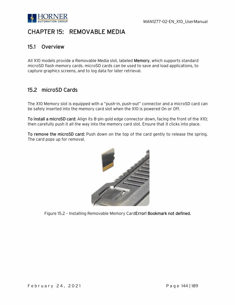
MAN1277-02-EN_X10_UserManual
F e b r u a r y 2 4 , 2 0 2 1 P a g e 144 | 189
CHAPTER 15: REMOVABLE MEDIA
15.1 Overview
All X10 models provide a Removable Media slot, labeled Memory, which supports standard microSD flash memory cards. microSD cards can be used to save and load applications, to capture graphics screens, and to log data for later retrieval.
15.2 microSD Cards
The X10 Memory slot is equipped with a “push-in, push-out” connector and a microSD card can be safely inserted into the memory card slot when the X10 is powered On or Off. To install a microSD card: Align its 8-pin gold edge connector down, facing the front of the X10; then carefully push it all the way into the memory card slot. Ensure that it clicks into place. To remove the microSD card: Push down on the top of the card gently to release the spring. The card pops up for removal.
Figure 15.2 – Installing Removable Memory CardError! Bookmark not defined.
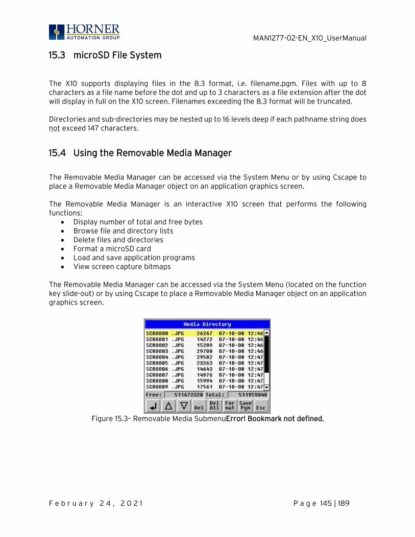
MAN1277-02-EN_X10_UserManual
F e b r u a r y 2 4 , 2 0 2 1 P a g e 145 | 189
15.3 microSD File System
The X10 supports displaying files in the 8.3 format, i.e. filename.pgm. Files with up to 8 characters as a file name before the dot and up to 3 characters as a file extension after the dot will display in full on the X10 screen. Filenames exceeding the 8.3 format will be truncated. Directories and sub-directories may be nested up to 16 levels deep if each pathname string does not exceed 147 characters.
15.4 Using the Removable Media Manager
The Removable Media Manager can be accessed via the System Menu or by using Cscape to place a Removable Media Manager object on an application graphics screen. The Removable Media Manager is an interactive X10 screen that performs the following functions:
• Display number of total and free bytes • Browse file and directory lists • Delete files and directories • Format a microSD card • Load and save application programs • View screen capture bitmaps
The Removable Media Manager can be accessed via the System Menu (located on the function key slide-out) or by using Cscape to place a Removable Media Manager object on an application graphics screen.
Figure 15.3– Removable Media SubmenuError! Bookmark not defined.

MAN1277-02-EN_X10_UserManual
F e b r u a r y 2 4 , 2 0 2 1 P a g e 146 | 189
15.5 Using Removable Media to Log Data
Using Read and Write Removable Media function blocks, an application ladder program can read and write X10 register data in the form of comma-delimited files, with a .CSV extension. These files are compatible with standard database and spreadsheet PC programs. In addition, an application ladder program can use Rename and Delete Removable Media function blocks to rename and delete files.
15.6 Using Removable Media to Load and Save Applications
A special file type, with a .PGM extension, is used to store X10 application programs on microSD. To load an application from microSD to the X10, use the Removable Media Manager to find and highlight the desired .PGM file, and then press the Enter key. To save an application from the X10 to microSD, open the Removable Media Manager in the
System Menu and press the Save Pgm function key. The application will be saved in a file called DEFAULT.PGM in the microSD root directory
NOTE: Saving an application to microSD can only be done from the System Menu and is not available on a Removable Media Manager object that is placed on an application graphics screen by Cscape.
NOTE: Saving an application to microSD does not also save register data.
Cscape can also save an application directly to a microSD card, which is plugged into the PC’s microSD compatible card reader by selecting the Export to Removable Media item on the File menu.

MAN1277-02-EN_X10_UserManual
F e b r u a r y 2 4 , 2 0 2 1 P a g e 147 | 189
15.7 Using Removable Media to View and Capture Screens
The X10 OCS File System uses bitmap files with the .BMP extension or JPEG files with the .JPG extension to store X10 OCS graphic screen captures. To view a captured an X10 OCS screen, use the Removable Media Manager to find and highlight
the desired .BMP or .JPG file, and then press Enter.
To capture an X10 OCS screen, turning On the assigned Screen Capture Control Register will capture the current X10 OCS graphics screen and write it to the microSD card using the assigned Screen Capture Filename. Before capturing an X10 OCS screen, Cscape must first be used to assign a Screen Capture Control Register and Filename in the application. To do this, first open the Graphics Editor by selecting the View / Edit Screens item on the Cscape Screens menu. Next, select the Screen Capture item of the Graphics Editor Config menu and then enter a Control Register and Filename.
15.8 Configuration of a Removable Media
The configuration of the Removable Media Object that invokes the Removable Media Viewer defines what buttons are enabled and available to the user. The (Enter) button performs certain operations based on the selected file’s type: .. - change display to parent directory <DIR> - change display to child directory pgm - load application (if compatible model and version) Alternately, by checking the ‘Write Selected Filename’ option, the RM Manager object will load the currently displayed path and filename into a block of registers for use with other Removable Media functions. The register block is assigned in the ‘File Select’ config found in the Config menu of the graphic/screen editor. Once view operations are complete, simply touch the Esc button to remove the pop-up removable media viewer.

MAN1277-02-EN_X10_UserManual
F e b r u a r y 2 4 , 2 0 2 1 P a g e 148 | 189
15.9 Removable Media (RM) Features—Program Logic
NOTE: For detailed information regarding RM function blocks and parameters, refer to the help file in Cscape Software. The following RM function blocks are available in Cscape Software. These function blocks will reference microSD when filename is prefixed with ‘A:’ or nothing a. Read RM csv—This function allows reading of a comma-separated value file from the microSD interface into the controller register space. b. Write RM csv—This function allows writing of a comma-separated value file to the microSD interface from the controller register space. c. Rename RM csv—This function allows renaming a file on the RM card. The data in the file is not changed.
d. Delete RM csv—This function allows deleting a file on the RM card.
e. Copy RM csv—This function can be used to copy files from A: to B: or vice versa. The data in the file is not changed. Additional features that utilize the Removable Media port are the datalog and report features, as well as graphic editor options: alarm and trend objects, screen capture, filename counters, and file select.
MAN1277-02-EN_X10_UserManual
F e b r u a r y 2 4 , 2 0 2 1 P a g e 149 | 189
15.10 Removable Media (RM) Features— Program Features
a. Datalog Configuration—This feature allows the controller to periodically log register values to Removable Media. The register data is stored in .csv (comma separated value) format, which is compatible with 3rd party PC applications, such as Microsoft Excel. b. Report Editor—This feature allows the OCS to be configured to generate text printouts which incorporate data from the registers embedded in the text. The reports can be printed using a serial interface printer through any of the serial ports of the OCS or can be saved on the removable media of the device. c. Recipes Editor—Recipes allow the user to send or update multiple registers simultaneously.
15.11 Removable Media (RM) Features—Graphic/Screen Editor
a. Trends—The historic support feature in the trend object utilizes Removable Media. b. Removable Media—This is a graphic object used to access files and functions pertaining to Removable Media. c. Recipes—This is a graphic object that is used in conjunction with the recipe editor which is mentioned above.
15.12 Removable Media Features—Additional Configuration
a. Alarms—Alarm data can be logged to a .csv file stored on Removable Media. b. Screen Capture—The screen capture function allows a bitmap or jpeg image of the displayed OCS screen to be written to the Removable Media card. c. Filename Counters— The filename counters can be accessed wherever Removable Media functions require a path name. A typical application is the auto-incrementing of a file name when doing screen captures. d. File Select— File Select is used to specify the register block that is used with the Removable Media Manager object ‘Write Selected Filename’ option.
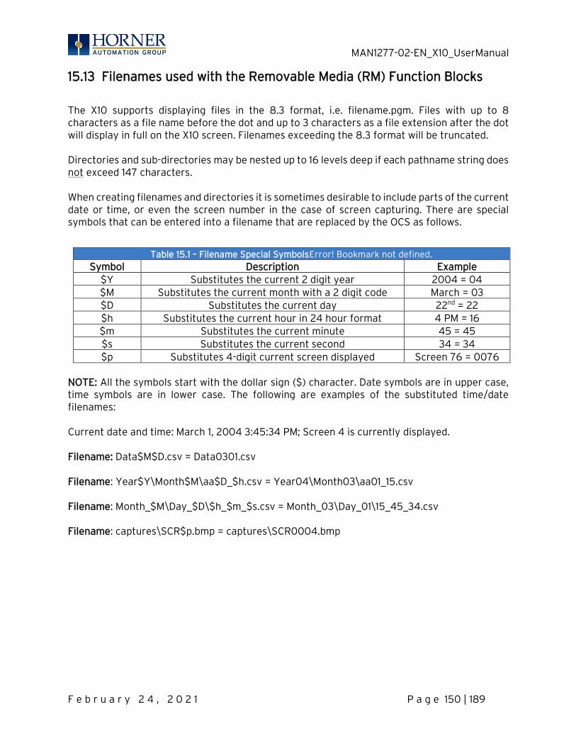
MAN1277-02-EN_X10_UserManual
F e b r u a r y 2 4 , 2 0 2 1 P a g e 150 | 189
15.13 Filenames used with the Removable Media (RM) Function Blocks
The X10 supports displaying files in the 8.3 format, i.e. filename.pgm. Files with up to 8 characters as a file name before the dot and up to 3 characters as a file extension after the dot will display in full on the X10 screen. Filenames exceeding the 8.3 format will be truncated. Directories and sub-directories may be nested up to 16 levels deep if each pathname string does not exceed 147 characters. When creating filenames and directories it is sometimes desirable to include parts of the current date or time, or even the screen number in the case of screen capturing. There are special symbols that can be entered into a filename that are replaced by the OCS as follows.
Table 15.1 – Filename Special SymbolsError! Bookmark not defined. Symbol Description Example
$Y Substitutes the current 2 digit year 2004 = 04 $M Substitutes the current month with a 2 digit code March = 03 $D Substitutes the current day 22nd = 22 $h Substitutes the current hour in 24 hour format 4 PM = 16 $m Substitutes the current minute 45 = 45 $s Substitutes the current second 34 = 34 $p Substitutes 4-digit current screen displayed Screen 76 = 0076
NOTE: All the symbols start with the dollar sign ($) character. Date symbols are in upper case, time symbols are in lower case. The following are examples of the substituted time/date filenames: Current date and time: March 1, 2004 3:45:34 PM; Screen 4 is currently displayed. Filename: Data$M$D.csv = Data0301.csv Filename: Year$Y\Month$M\aa$D_$h.csv = Year04\Month03\aa01_15.csv Filename: Month_$M\Day_$D\$h_$m_$s.csv = Month_03\Day_01\15_45_34.csv Filename: captures\SCR$p.bmp = captures\SCR0004.bmp
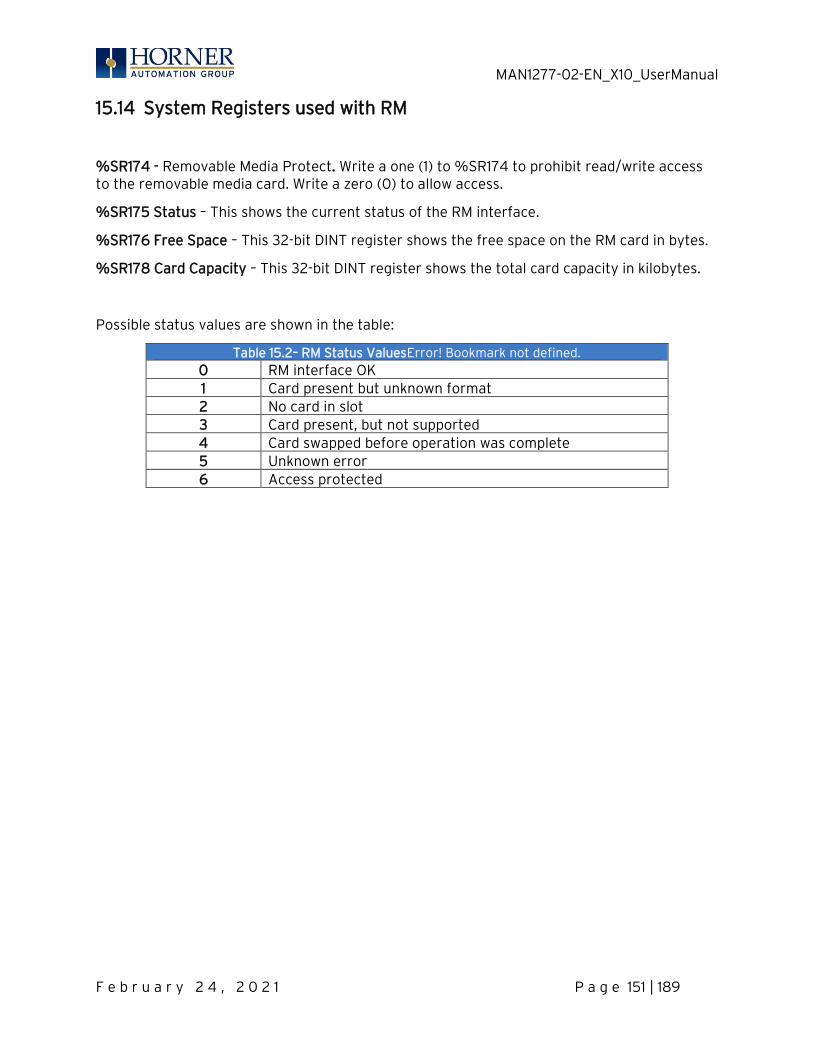
MAN1277-02-EN_X10_UserManual
F e b r u a r y 2 4 , 2 0 2 1 P a g e 151 | 189
15.14 System Registers used with RM
%SR174 - Removable Media Protect. Write a one (1) to %SR174 to prohibit read/write access to the removable media card. Write a zero (0) to allow access.
%SR175 Status – This shows the current status of the RM interface.
%SR176 Free Space – This 32-bit DINT register shows the free space on the RM card in bytes.
%SR178 Card Capacity – This 32-bit DINT register shows the total card capacity in kilobytes.
Possible status values are shown in the table:
Table 15.2– RM Status ValuesError! Bookmark not defined. 0 RM interface OK 1 Card present but unknown format 2 No card in slot 3 Card present, but not supported 4 Card swapped before operation was complete 5 Unknown error 6 Access protected
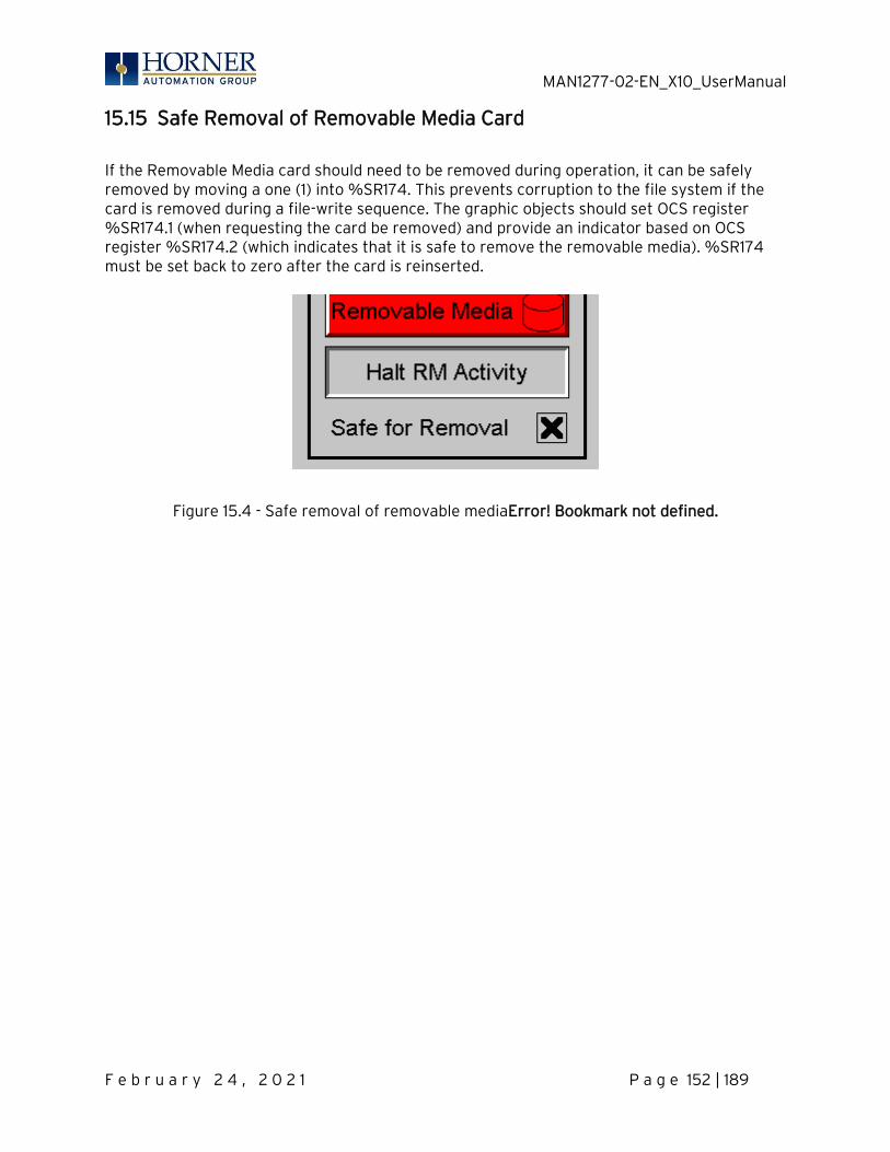
MAN1277-02-EN_X10_UserManual
F e b r u a r y 2 4 , 2 0 2 1 P a g e 152 | 189
15.15 Safe Removal of Removable Media Card
If the Removable Media card should need to be removed during operation, it can be safely removed by moving a one (1) into %SR174. This prevents corruption to the file system if the card is removed during a file-write sequence. The graphic objects should set OCS register %SR174.1 (when requesting the card be removed) and provide an indicator based on OCS register %SR174.2 (which indicates that it is safe to remove the removable media). %SR174 must be set back to zero after the card is reinserted.
Figure 15.4 - Safe removal of removable mediaError! Bookmark not defined.
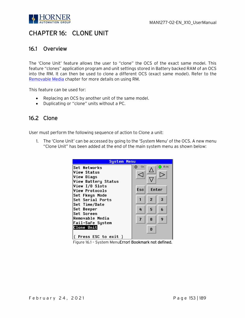
MAN1277-02-EN_X10_UserManual
F e b r u a r y 2 4 , 2 0 2 1 P a g e 153 | 189
CHAPTER 16: CLONE UNIT
16.1 Overview
The ‘Clone Unit’ feature allows the user to “clone” the OCS of the exact same model. This feature “clones” application program and unit settings stored in Battery backed RAM of an OCS into the RM. It can then be used to clone a different OCS (exact same model). Refer to the Removable Media chapter for more details on using RM. This feature can be used for:
• Replacing an OCS by another unit of the same model. • Duplicating or “clone” units without a PC.
16.2 Clone
User must perform the following sequence of action to Clone a unit:
1. The ‘Clone Unit’ can be accessed by going to the ‘System Menu’ of the OCS. A new menu “Clone Unit” has been added at the end of the main system menu as shown below:
Figure 16.1 – System MenuError! Bookmark not defined.
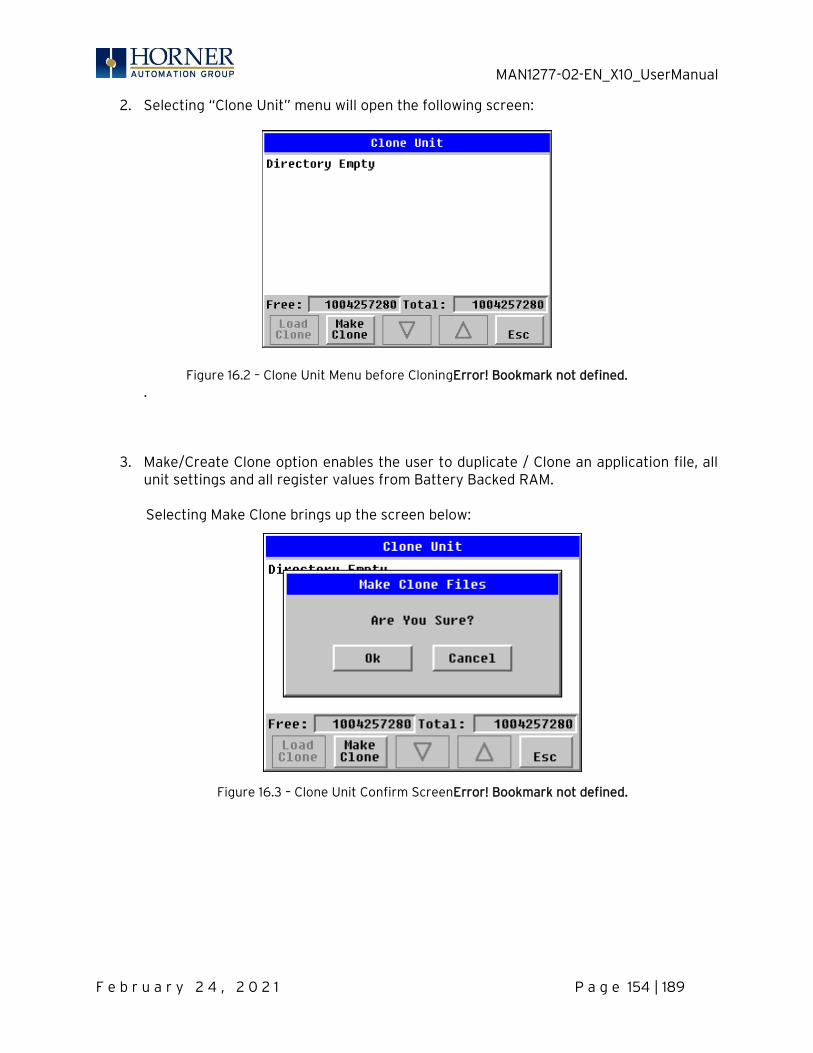
MAN1277-02-EN_X10_UserManual
F e b r u a r y 2 4 , 2 0 2 1 P a g e 154 | 189
2. Selecting “Clone Unit” menu will open the following screen:
Figure 16.2 – Clone Unit Menu before CloningError! Bookmark not defined. .
3. Make/Create Clone option enables the user to duplicate / Clone an application file, all unit settings and all register values from Battery Backed RAM.
Selecting Make Clone brings up the screen below:
Figure 16.3 – Clone Unit Confirm ScreenError! Bookmark not defined.
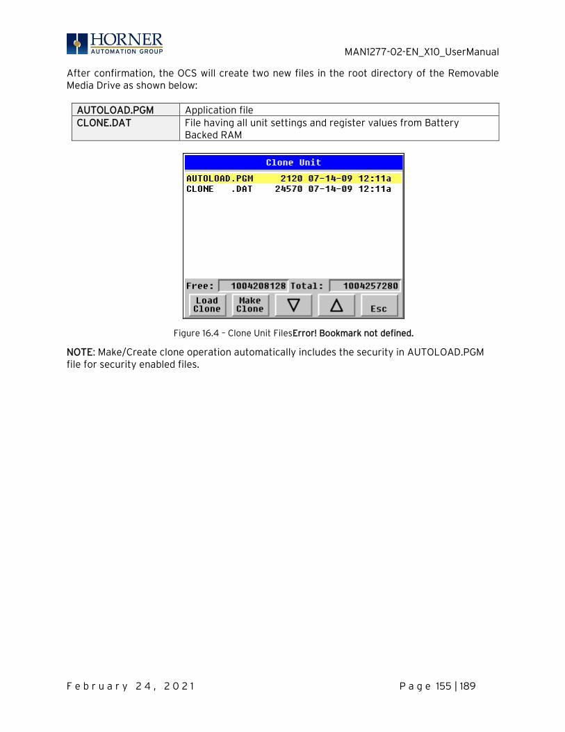
MAN1277-02-EN_X10_UserManual
F e b r u a r y 2 4 , 2 0 2 1 P a g e 155 | 189
After confirmation, the OCS will create two new files in the root directory of the Removable Media Drive as shown below:
AUTOLOAD.PGM Application file CLONE.DAT File having all unit settings and register values from Battery
Backed RAM
Figure 16.4 – Clone Unit FilesError! Bookmark not defined.
NOTE: Make/Create clone operation automatically includes the security in AUTOLOAD.PGM file for security enabled files.
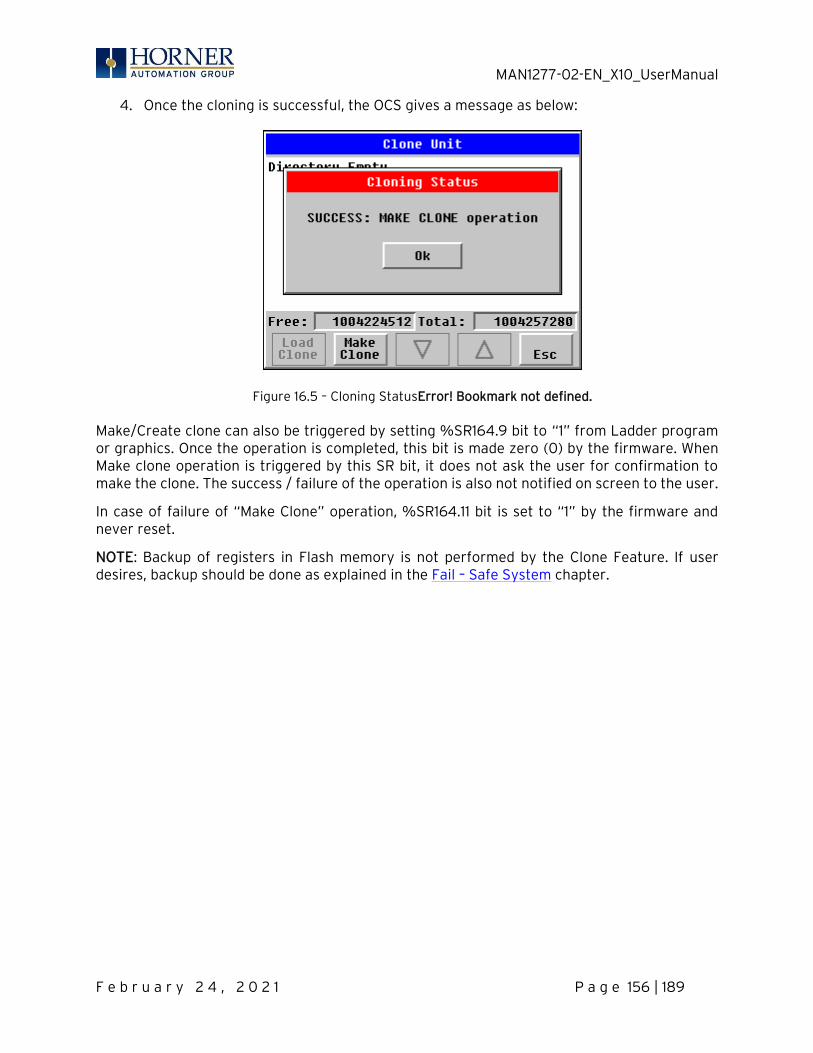
MAN1277-02-EN_X10_UserManual
F e b r u a r y 2 4 , 2 0 2 1 P a g e 156 | 189
4. Once the cloning is successful, the OCS gives a message as below:
Figure 16.5 – Cloning StatusError! Bookmark not defined.
Make/Create clone can also be triggered by setting %SR164.9 bit to “1” from Ladder program or graphics. Once the operation is completed, this bit is made zero (0) by the firmware. When Make clone operation is triggered by this SR bit, it does not ask the user for confirmation to make the clone. The success / failure of the operation is also not notified on screen to the user.
In case of failure of “Make Clone” operation, %SR164.11 bit is set to “1” by the firmware and never reset.
NOTE: Backup of registers in Flash memory is not performed by the Clone Feature. If user desires, backup should be done as explained in the Fail – Safe System chapter.
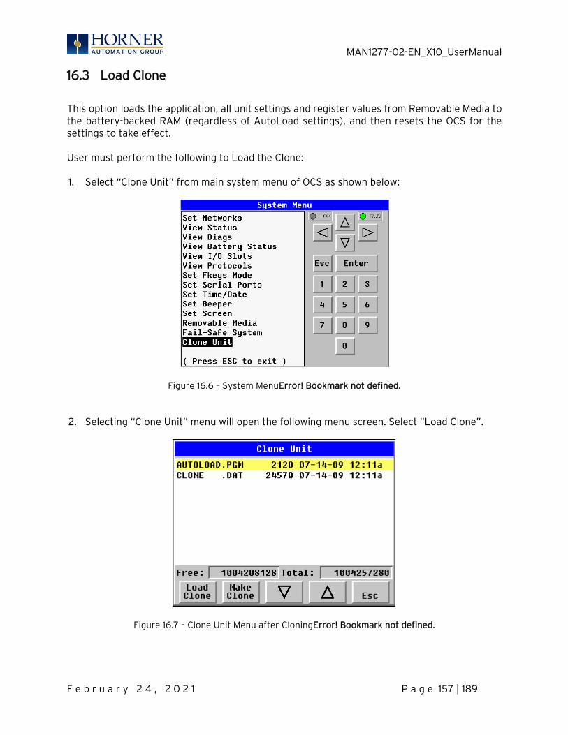
MAN1277-02-EN_X10_UserManual
F e b r u a r y 2 4 , 2 0 2 1 P a g e 157 | 189
16.3 Load Clone
This option loads the application, all unit settings and register values from Removable Media to the battery-backed RAM (regardless of AutoLoad settings), and then resets the OCS for the settings to take effect. User must perform the following to Load the Clone: 1. Select “Clone Unit” from main system menu of OCS as shown below:
Figure 16.6 – System MenuError! Bookmark not defined. 2. Selecting “Clone Unit” menu will open the following menu screen. Select “Load Clone”.
Figure 16.7 – Clone Unit Menu after CloningError! Bookmark not defined.
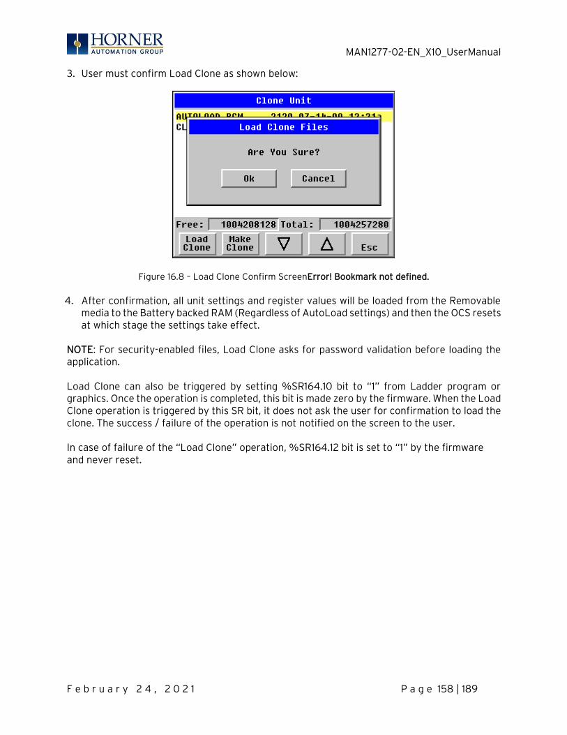
MAN1277-02-EN_X10_UserManual
F e b r u a r y 2 4 , 2 0 2 1 P a g e 158 | 189
3. User must confirm Load Clone as shown below:
Figure 16.8 – Load Clone Confirm ScreenError! Bookmark not defined. 4. After confirmation, all unit settings and register values will be loaded from the Removable
media to the Battery backed RAM (Regardless of AutoLoad settings) and then the OCS resets at which stage the settings take effect.
NOTE: For security-enabled files, Load Clone asks for password validation before loading the application. Load Clone can also be triggered by setting %SR164.10 bit to “1” from Ladder program or graphics. Once the operation is completed, this bit is made zero by the firmware. When the Load Clone operation is triggered by this SR bit, it does not ask the user for confirmation to load the clone. The success / failure of the operation is not notified on the screen to the user. In case of failure of the “Load Clone” operation, %SR164.12 bit is set to “1” by the firmware and never reset.
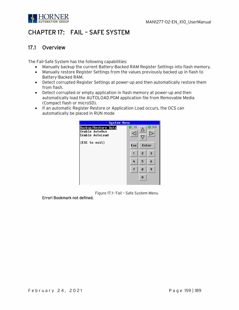
MAN1277-02-EN_X10_UserManual
F e b r u a r y 2 4 , 2 0 2 1 P a g e 159 | 189
CHAPTER 17: FAIL – SAFE SYSTEM
17.1 Overview
The Fail-Safe System has the following capabilities:
• Manually backup the current Battery-Backed RAM Register Settings into flash memory. • Manually restore Register Settings from the values previously backed up in flash to
Battery-Backed RAM. • Detect corrupted Register Settings at power-up and then automatically restore them
from flash. • Detect corrupted or empty application in flash memory at power-up and then
automatically load the AUTOLOAD.PGM application file from Removable Media (Compact flash or microSD).
• If an automatic Register Restore or Application Load occurs, the OCS can automatically be placed in RUN mode
Figure 17.1– Fail – Safe System Menu Error! Bookmark not defined.
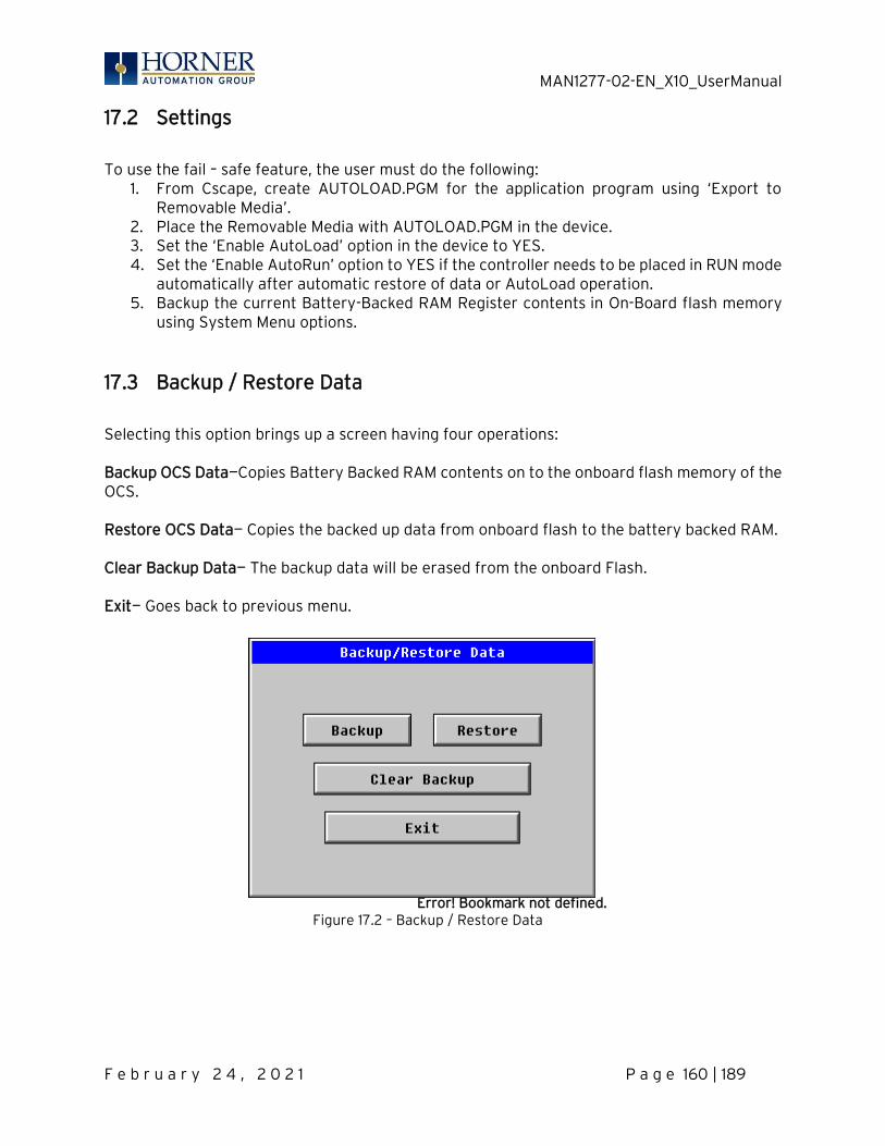
MAN1277-02-EN_X10_UserManual
F e b r u a r y 2 4 , 2 0 2 1 P a g e 160 | 189
17.2 Settings
To use the fail – safe feature, the user must do the following:
1. From Cscape, create AUTOLOAD.PGM for the application program using ‘Export to Removable Media’.
2. Place the Removable Media with AUTOLOAD.PGM in the device. 3. Set the ‘Enable AutoLoad’ option in the device to YES. 4. Set the ‘Enable AutoRun’ option to YES if the controller needs to be placed in RUN mode
automatically after automatic restore of data or AutoLoad operation. 5. Backup the current Battery-Backed RAM Register contents in On-Board flash memory
using System Menu options.
17.3 Backup / Restore Data
Selecting this option brings up a screen having four operations: Backup OCS Data—Copies Battery Backed RAM contents on to the onboard flash memory of the OCS. Restore OCS Data— Copies the backed up data from onboard flash to the battery backed RAM. Clear Backup Data— The backup data will be erased from the onboard Flash. Exit— Goes back to previous menu.
Error! Bookmark not defined.
Figure 17.2 – Backup / Restore Data
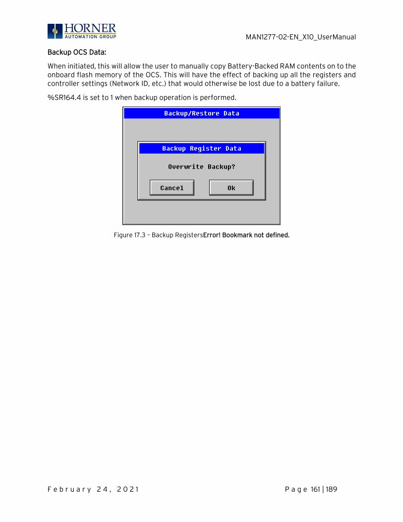
MAN1277-02-EN_X10_UserManual
F e b r u a r y 2 4 , 2 0 2 1 P a g e 161 | 189
Backup OCS Data:
When initiated, this will allow the user to manually copy Battery-Backed RAM contents on to the onboard flash memory of the OCS. This will have the effect of backing up all the registers and controller settings (Network ID, etc.) that would otherwise be lost due to a battery failure.
%SR164.4 is set to 1 when backup operation is performed.
Figure 17.3 – Backup RegistersError! Bookmark not defined.
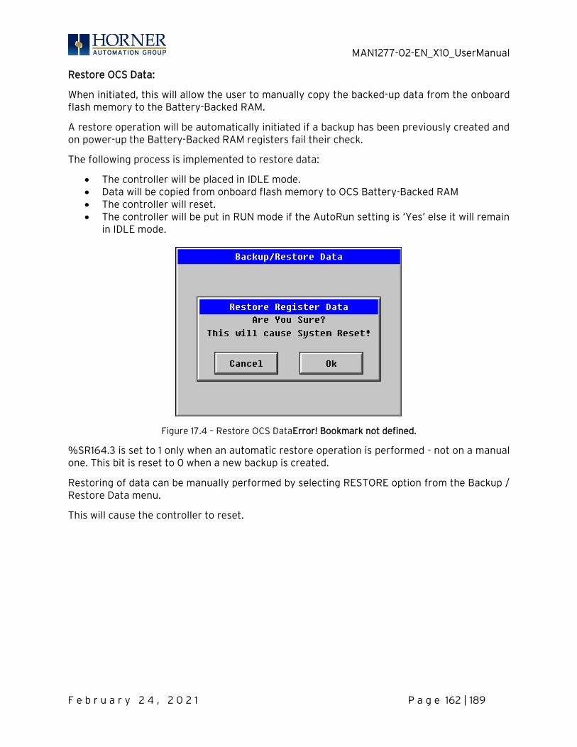
MAN1277-02-EN_X10_UserManual
F e b r u a r y 2 4 , 2 0 2 1 P a g e 162 | 189
Restore OCS Data:
When initiated, this will allow the user to manually copy the backed-up data from the onboard flash memory to the Battery-Backed RAM.
A restore operation will be automatically initiated if a backup has been previously created and on power-up the Battery-Backed RAM registers fail their check.
The following process is implemented to restore data:
• The controller will be placed in IDLE mode. • Data will be copied from onboard flash memory to OCS Battery-Backed RAM • The controller will reset. • The controller will be put in RUN mode if the AutoRun setting is ‘Yes’ else it will remain
in IDLE mode.
Figure 17.4 – Restore OCS DataError! Bookmark not defined.
%SR164.3 is set to 1 only when an automatic restore operation is performed - not on a manual one. This bit is reset to 0 when a new backup is created.
Restoring of data can be manually performed by selecting RESTORE option from the Backup / Restore Data menu.
This will cause the controller to reset.
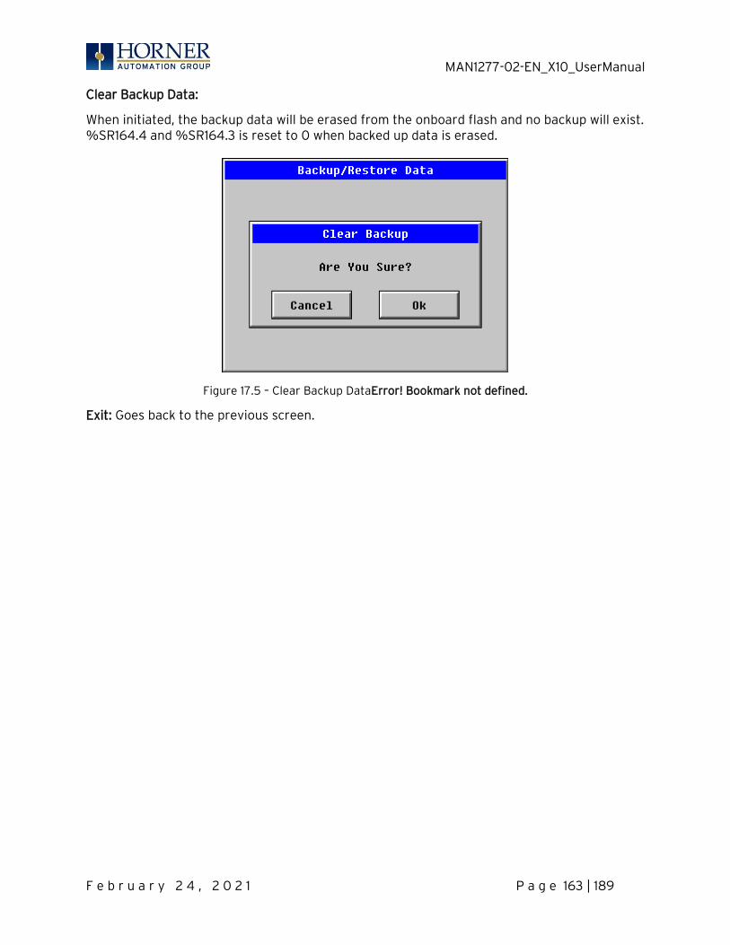
MAN1277-02-EN_X10_UserManual
F e b r u a r y 2 4 , 2 0 2 1 P a g e 163 | 189
Clear Backup Data:
When initiated, the backup data will be erased from the onboard flash and no backup will exist. %SR164.4 and %SR164.3 is reset to 0 when backed up data is erased.
Figure 17.5 – Clear Backup DataError! Bookmark not defined.
Exit: Goes back to the previous screen.
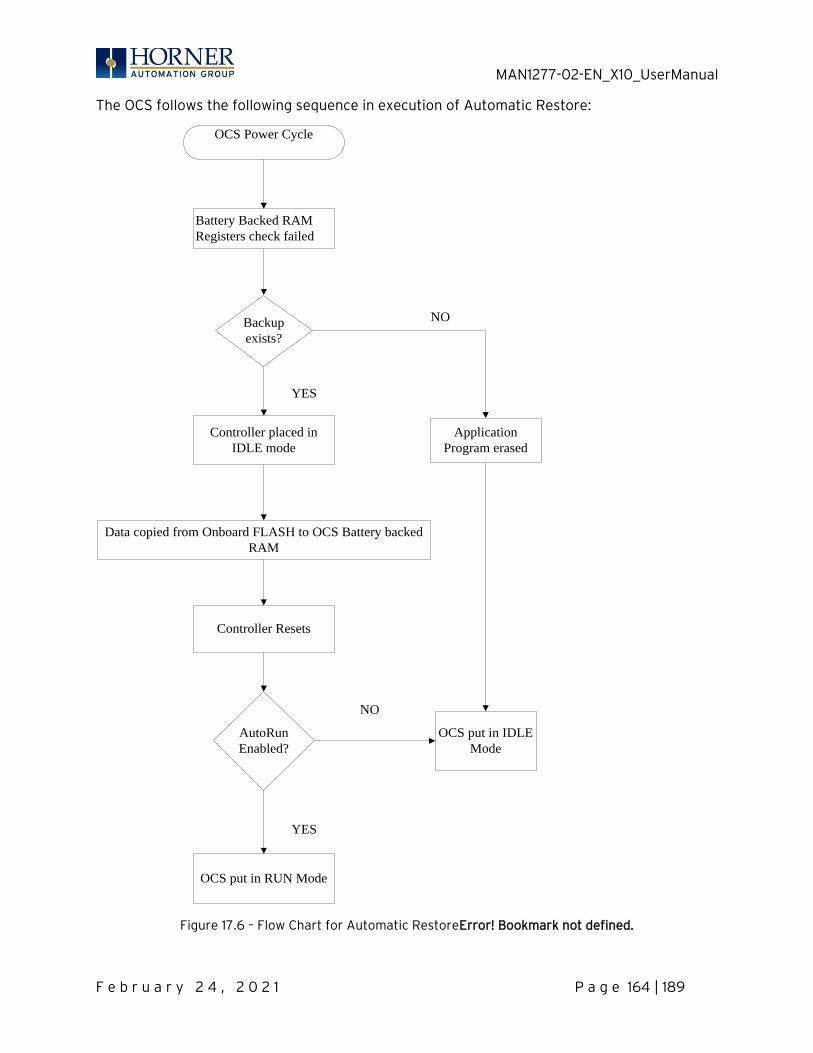
MAN1277-02-EN_X10_UserManual
F e b r u a r y 2 4 , 2 0 2 1 P a g e 164 | 189
The OCS follows the following sequence in execution of Automatic Restore:
OCS Power Cycle
Battery Backed RAM
Registers check failed
Backup
exists?
Controller placed in
IDLE mode
Data copied from Onboard FLASH to OCS Battery backed
RAM
Controller Resets
AutoRun
Enabled?
OCS put in RUN Mode
OCS put in IDLE
Mode
NO
YES
YES
NO
Application
Program erased
Figure 17.6 – Flow Chart for Automatic RestoreError! Bookmark not defined.
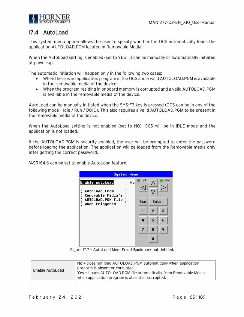
MAN1277-02-EN_X10_UserManual
F e b r u a r y 2 4 , 2 0 2 1 P a g e 165 | 189
17.4 AutoLoad
This system menu option allows the user to specify whether the OCS automatically loads the application AUTOLOAD.PGM located in Removable Media. When the AutoLoad setting is enabled (set to YES), it can be manually or automatically initiated at power-up. The automatic initiation will happen only in the following two cases:
• When there is no application program in the OCS and a valid AUTOLOAD.PGM is available in the removable media of the device.
• When the program residing in onboard memory is corrupted and a valid AUTOLOAD.PGM is available in the removable media of the device.
AutoLoad can be manually initiated when the SYS-F3 key is pressed (OCS can be in any of the following mode – Idle / Run / DOIO). This also requires a valid AUTOLOAD.PGM to be present in the removable media of the device. When the AutoLoad setting is not enabled (set to NO), OCS will be in IDLE mode and the application is not loaded. If the AUTOLOAD.PGM is security enabled, the user will be prompted to enter the password before loading the application. The application will be loaded from the Removable media only after getting the correct password. %SR164.6 can be set to enable AutoLoad feature.
Figure 17.7 – AutoLoad MenuError! Bookmark not defined.
Enable AutoLoad
No = Does not load AUTOLOAD.PGM automatically when application program is absent or corrupted. Yes = Loads AUTOLOAD.PGM file automatically from Removable Media when application program is absent or corrupted.
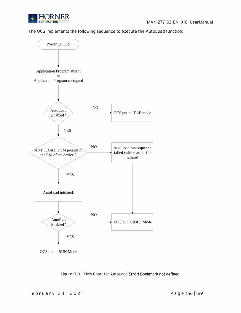
MAN1277-02-EN_X10_UserManual
F e b r u a r y 2 4 , 2 0 2 1 P a g e 166 | 189
The OCS implements the following sequence to execute the AutoLoad function:
Power up OCS
Application Program absent
or
Application Program corrupted
AutoLoad
Enabled?
AUTOLOAD.PGM present in
the RM of the device ?
AutoLoad initiated.
OCS put in IDLE mode
AutoLoad run sequence
failed (with reasons for
failure)
NO
NO
YES
YES
AutoRun
Enabled?
OCS put in RUN Mode
OCS put in IDLE Mode
NO
YES
Figure 17.8 – Flow Chart for AutoLoad Error! Bookmark not defined.
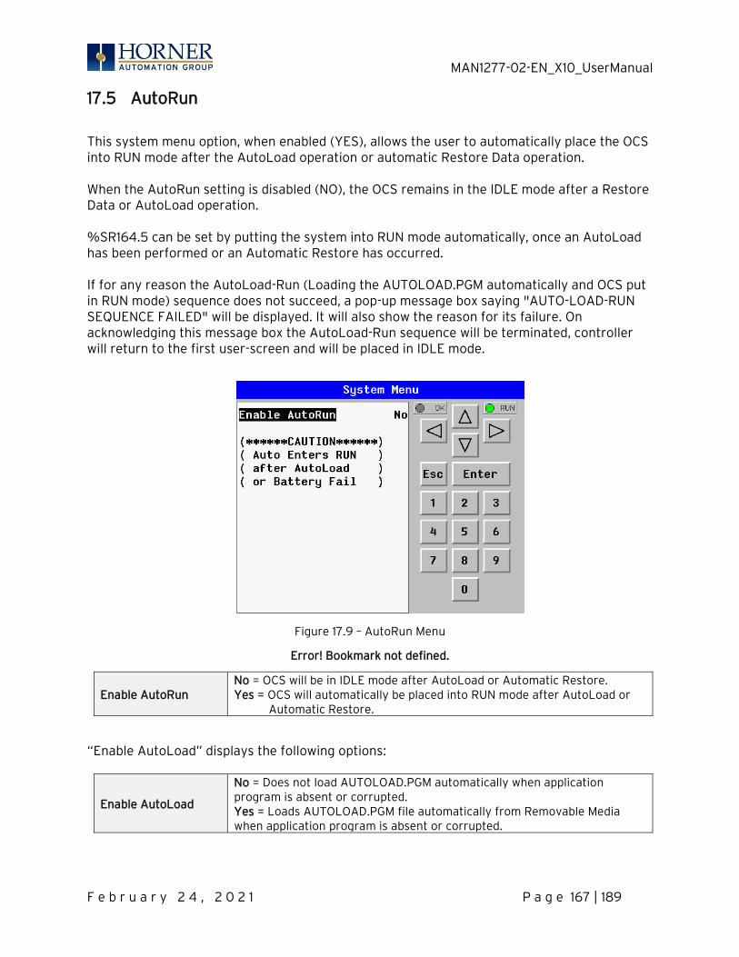
MAN1277-02-EN_X10_UserManual
F e b r u a r y 2 4 , 2 0 2 1 P a g e 167 | 189
17.5 AutoRun
This system menu option, when enabled (YES), allows the user to automatically place the OCS into RUN mode after the AutoLoad operation or automatic Restore Data operation. When the AutoRun setting is disabled (NO), the OCS remains in the IDLE mode after a Restore Data or AutoLoad operation. %SR164.5 can be set by putting the system into RUN mode automatically, once an AutoLoad has been performed or an Automatic Restore has occurred. If for any reason the AutoLoad-Run (Loading the AUTOLOAD.PGM automatically and OCS put in RUN mode) sequence does not succeed, a pop-up message box saying "AUTO-LOAD-RUN SEQUENCE FAILED" will be displayed. It will also show the reason for its failure. On acknowledging this message box the AutoLoad-Run sequence will be terminated, controller will return to the first user-screen and will be placed in IDLE mode.
Figure 17.9 – AutoRun Menu
Error! Bookmark not defined.
Enable AutoRun No = OCS will be in IDLE mode after AutoLoad or Automatic Restore. Yes = OCS will automatically be placed into RUN mode after AutoLoad or Automatic Restore.
“Enable AutoLoad” displays the following options:
Enable AutoLoad
No = Does not load AUTOLOAD.PGM automatically when application program is absent or corrupted. Yes = Loads AUTOLOAD.PGM file automatically from Removable Media when application program is absent or corrupted.
MAN1277-02-EN_X10_UserManual
F e b r u a r y 2 4 , 2 0 2 1 P a g e 168 | 189
CHAPTER 18: MODBUS COMMUNICATIONS
18.1 Modbus Overview
For complete Modbus instructions, please refer to the Help file in Cscape. Modbus (serial) is a popular, de-facto standard protocol that allows industrial devices from multiple manufacturers to easily share data in real-time. For Modbus serial communications, the X10 can act as either a Master or a Slave. Modbus protocol (serial) allows for one master and multiple slaves. The master always initiates the conversation by sending a request to a particular slave. Only the addressed slave will send a response when the request is completed. Should the slave be unable to complete the request, it returns the appropriate error response. Should the slave be unable to respond, the master’s timeout timer expires to provide an indication of No Response.
18.2 Modbus Slave Overview
For complete Modbus Slave instructions, please refer to the Help file in Cscape. The Modbus slave function block, when used with the appropriate Modem and/or Open function blocks, allows the primary serial port on the controller to act as a Modbus slave. The Modbus function supports both ASCII and RTU modes of operation across a range of baud rates and protocol frames. Also supported is port activity status, an inactivity timer, support for call-on exception, and support for store and forward (repeater) operation for radio modems. The Modbus Addressing section shows the supported Modbus Commands as well as the Modbus Map for X10 References (%R, %M, etc.).

MAN1277-02-EN_X10_UserManual
F e b r u a r y 2 4 , 2 0 2 1 P a g e 169 | 189
18.3 Modbus Master Overview
For complete Modbus Master instructions, please refer to the Help file in Cscape. When acting as a Modbus master, there are two primary mechanisms used by the X10 to allow the user to specify the data to be read/written from/to the slaves. Modbus Master Function Block—This is for serial only. This is an advanced feature that should only be used in rare occasions.
Protocol Config—The Protocol Config is configured in the Hardware Configuration dialog box in Cscape (serial). This is the preferred method in most applications. After the protocol has been selected from the dropdown menu, the Network, Devices, and Scan List become available. The Protocol Config is configured on three different levels:
• Network—Parameters, such as the polling rate of the data scan, are specified along with timeout values, retry, and re-acquisition settings. Serial configuration, baud rate, parity, etc. are also set here.
• Devices—For every slave to be polled, configuration details are added in the Devices dialog box. This includes Slave ID (serial). Under Device Type, the Modbus addressing style matching that specified in the slave’s user documentation may be selected. For instance, some slaves specify Modbus addresses (i.e. 40,001), and others specify offsets (i.e. 0000).
o Hex or Decimal—Some specify addresses in hex, and others in decimal. By allowing the user to select the Modbus addressing style for each slave on the network, minimal address conversion is required. Also, if the slave is another Horner product (i.e. another OCS), the “Native Addressing” option can be selected (i.e. %R1, %M17, etc.), and this skips the conversion to Modbus style altogether.
• Scan List—This is where the specific Modbus addresses to be read/written from/to each slave are specified. Up to 32 words of data can be read at the same time. NOTE: Once configuration has been completed on the Network and Devices level, Modbus data can be directly read/written from graphics objects in the Cscape screen editor. This is available even if the Modbus register is not listed on the scan list.
The above information is just an introduction to the topic. For more detailed information, please consult the Cscape Help file.
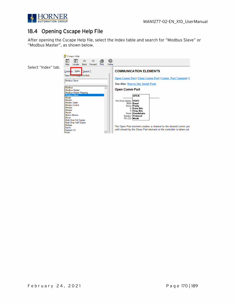
MAN1277-02-EN_X10_UserManual
F e b r u a r y 2 4 , 2 0 2 1 P a g e 170 | 189
18.4 Opening Cscape Help File
After opening the Cscape Help file, select the Index table and search for “Modbus Slave” or “Modbus Master”, as shown below.
Select “Index” tab.
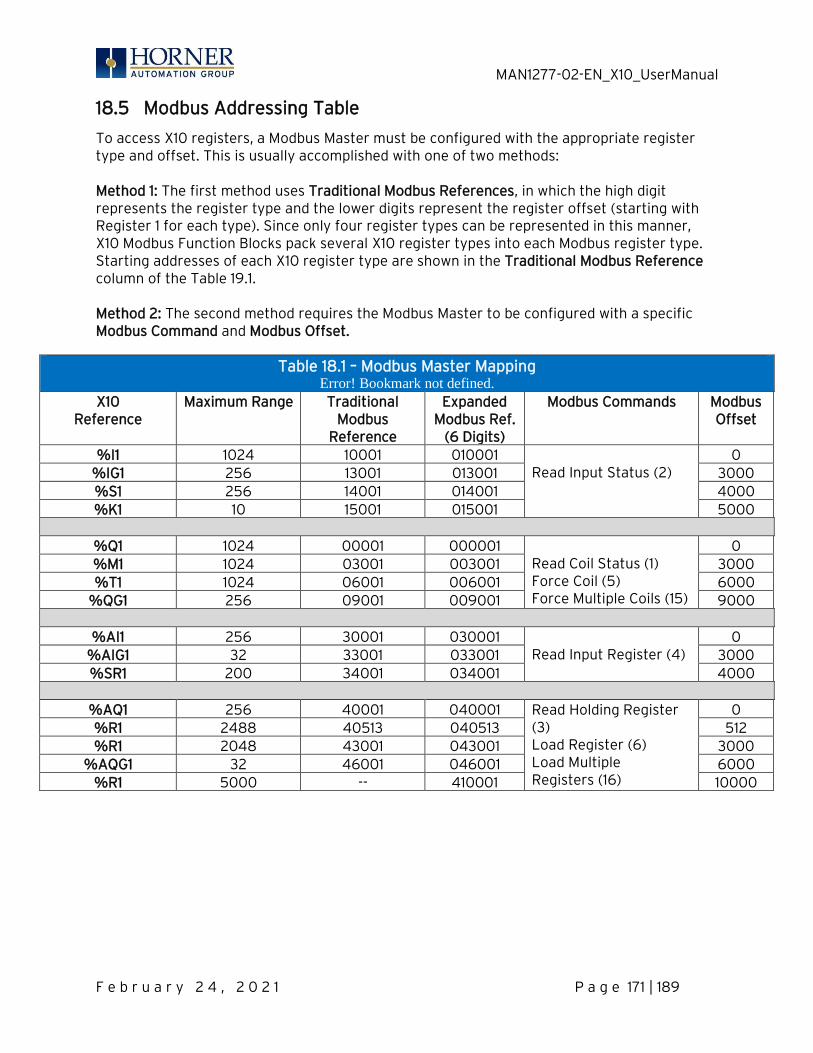
MAN1277-02-EN_X10_UserManual
F e b r u a r y 2 4 , 2 0 2 1 P a g e 171 | 189
18.5 Modbus Addressing Table
To access X10 registers, a Modbus Master must be configured with the appropriate register type and offset. This is usually accomplished with one of two methods: Method 1: The first method uses Traditional Modbus References, in which the high digit represents the register type and the lower digits represent the register offset (starting with Register 1 for each type). Since only four register types can be represented in this manner, X10 Modbus Function Blocks pack several X10 register types into each Modbus register type. Starting addresses of each X10 register type are shown in the Traditional Modbus Reference column of the Table 19.1. Method 2: The second method requires the Modbus Master to be configured with a specific Modbus Command and Modbus Offset.
Table 18.1 – Modbus Master Mapping Error! Bookmark not defined.
X10 Reference
Maximum Range Traditional Modbus
Reference
Expanded Modbus Ref.
(6 Digits)
Modbus Commands Modbus Offset
%I1 1024 10001 010001 Read Input Status (2)
0 %IG1 256 13001 013001 3000 %S1 256 14001 014001 4000 %K1 10 15001 015001 5000
%Q1 1024 00001 000001
Read Coil Status (1) Force Coil (5) Force Multiple Coils (15)
0 %M1 1024 03001 003001 3000 %T1 1024 06001 006001 6000
%QG1 256 09001 009001 9000
%AI1 256 30001 030001 Read Input Register (4)
0 %AIG1 32 33001 033001 3000 %SR1 200 34001 034001 4000
%AQ1 256 40001 040001 Read Holding Register
(3) Load Register (6) Load Multiple Registers (16)
0 %R1 2488 40513 040513 512 %R1 2048 43001 043001 3000
%AQG1 32 46001 046001 6000 %R1 5000 -- 410001 10000
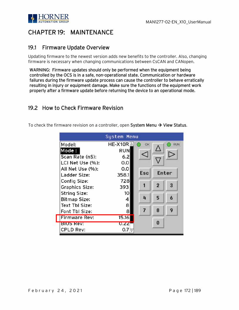
MAN1277-02-EN_X10_UserManual
F e b r u a r y 2 4 , 2 0 2 1 P a g e 172 | 189
CHAPTER 19: MAINTENANCE
19.1 Firmware Update Overview
Updating firmware to the newest version adds new benefits to the controller. Also, changing firmware is necessary when changing communications between CsCAN and CANopen.
WARNING: Firmware updates should only be performed when the equipment being controlled by the OCS is in a safe, non-operational state. Communication or hardware failures during the firmware update process can cause the controller to behave erratically resulting in injury or equipment damage. Make sure the functions of the equipment work properly after a firmware update before returning the device to an operational mode.
19.2 How to Check Firmware Revision
To check the firmware revision on a controller, open System Menu → View Status.

MAN1277-02-EN_X10_UserManual
F e b r u a r y 2 4 , 2 0 2 1 P a g e 173 | 189
19.3 Firmware Update Details
Note: Updating firmware will clear the application program, screens, configurations, and register data. If required, make sure to backup program and register data before updating firmware. The controller’s User Manual has instructions for doing backups.
There are three methods for updating firmware. The method used depends on the type of controller being updated.
Method A: Removable Media Method – The controller firmware is updated by a bootloader, using a microSD card.
To update or change firmware:
1) Download desired Firmware set from the Horner APG website. (Verify CsCAN or CANopen communications.)
2) Save Firmware files to microSD card or USB, these are the removable media devices. 3) Update the firmware through the controller’s Firmware Update function
NOTE: Files from the Horner website come as a .ZIP file which need to be unzipped and placed in the root of the drive for them to function properly.
Method B: RS232 Serial Connection – Serial firmware updates are done from Cscape software to the controller’s primary serial port, MJ1 in most cases.
Method C: Mini USB Port – The mini USB port can be used to update firmware in the X10. This is quicker than doing so via MJ1.

MAN1277-02-EN_X10_UserManual
F e b r u a r y 2 4 , 2 0 2 1 P a g e 174 | 189
Initial Step:
In North America, visit https://hornerautomation.com Then click Support → Downloads →Controller Firmware and download the most recent firmware set with the correct communication protocol.
-OR-
In Europe, visit http://www.hornerautomation.eu and click Support → Firmware tab and download the desired firmware (an account is required to access firmware updates, create one if necessary).
1. Establish communication between Cscape and the controller using a direct serial connection to MJ1 or USB.
2. Make sure your application is available on your PC or upload the application. 3. Make sure the machinery connected to the OCS is in a safe state for firmware
update. 4. Start the firmware update by selecting File → Firmware Update Wizard. 5. The correct product type should be selected, if it is not select the type of controller
from the drop-down list. 6. Press the Start button. 7. Wait for the firmware update to complete. 8. If there is a communication failure check the cable, connections and comm. port
setting and try again. 9. Firmware updates typically delete the user applications to ensure compatibility.
You will need to reload your application. 10. Test the operation of the equipment with the new firmware before returning the
OCS system to an operation mode.

MAN1277-02-EN_X10_UserManual
F e b r u a r y 2 4 , 2 0 2 1 P a g e 175 | 189
19.4 Firmware Update via microSD card
NOTE: Must have Firmware 15.40 or higher in place to be able to update firmware using the microSD card. NOTE: Applies to XLEe and XLTe (ethernet models) only.
19.4.1 Method 1 Placing “.s19” file in the root of microSD card and loading firmware manually and automatically. Manual firmware update by selecting “.s19” file Place “.s19” file in the root of microSD card and insert the card. Go to System menu | Removable media and select “.s19” file that needs to be loaded. Device displays the following message “Do not power Cycle Until FW is updated”, select OK. Firmware update will be started, and a busy symbol will be displayed on the device until firmware will be loaded. When firmware update will start %SR154.16 bit will be set to high. Once firmware update is completed %SR154.16 bits will be set to low. Set %SR154.12 bit to high before selecting “.s19” file / before loading firmware if user program and register data should be cleared after the update. Set %SR154.12 bit to low before selecting “.s19” file / before loading firmware if user program should be present, register values should be retained and status of the device needs to be retained after the update. Auto firmware update via %SR’s Place “.s19” file in the root of microSD card and insert the card. When %SR154.9 is set to high, %SR154.16 bit goes high and controller will update the firmware which is placed in the root directory of SD Card. Once firmware update process is successful, %SR154.9 and %SR154.16 bits are reset (goes low). NOTE: There will be no busy symbol indication for this method. User should monitor %SR’s for the updates. Set %SR154.12 bit to high if user program and register data should be cleared after the firmware update. Set %SR154.12 bit to low if user program should be present, register values should be retained and status of the device needs to be retained after the firmware update.
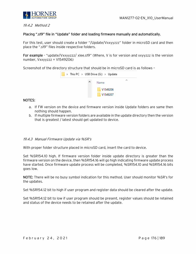
MAN1277-02-EN_X10_UserManual
F e b r u a r y 2 4 , 2 0 2 1 P a g e 176 | 189
19.4.2 Method 2 Placing “.s19” file in “Update” folder and loading firmware manually and automatically. For this test, user should create a folder “/Update/Vxxyyzzz” folder in microSD card and then place the “.s19” files inside respective folders. For example - “update/Vxxyyzzz/ xlee.s19” (Where, V is for version and xxyyzzz is the version number, Vxxyyzzz = V1549206) Screenshot of the directory structure that should be in microSD card is as follows –
NOTES:
a. If FW version on the device and firmware version inside Update folders are same then nothing should happen.
b. If multiple firmware version folders are available in the update directory then the version that is greatest / latest should get updated to device.
19.4.3 Manual Firmware Update via %SR’s With proper folder structure placed in microSD card, insert the card to device. Set %SR154.10 high. If firmware version folder inside update directory is greater than the firmware version on the device, then %SR154.16 will go high indicating firmware update process have started. Once firmware update process will be completed, %SR154.10 and %SR154.16 bits goes low. NOTE: There will be no busy symbol indication for this method. User should monitor %SR’s for the updates. Set %SR154.12 bit to high if user program and register data should be cleared after the update. Set %SR154.12 bit to low if user program should be present, register values should be retained and status of the device needs to be retained after the update.

MAN1277-02-EN_X10_UserManual
F e b r u a r y 2 4 , 2 0 2 1 P a g e 177 | 189
19.4.4 Auto firmware update via %SR’s Setting %SR154.10 and %SR154.11 high, whenever new firmware folder is placed in the microSD card, firmware update will happen automatically setting %SR154.16 bit high. Once firmware update process will be completed, %SR154.16 bit will be reset but %SR154.10 and %SR154.11 will remain high (for auto update of firmware). Note – There will be no busy symbol indication for this method. User should monitor %SR’s for the updates. Set %SR154.12 bit to high if user program and register data should be cleared after the update. Set %SR154.12 bit to low if user program should be present, register values should be retained and status of the device needs to be retained after the update. In all the methods, device will reset automatically after firmware update process is completed.

MAN1277-02-EN_X10_UserManual
F e b r u a r y 2 4 , 2 0 2 1 P a g e 178 | 189
19.5 Replacing Backup Battery
The X10 contains a run-time battery monitor that checks the voltage of the internal lithium battery. This battery is used to run the real-time clock and maintains retentive registers when power is disconnected. The battery will generally last seven (7) to ten (10) years. Environmental conditions, including extreme temperatures and humidity, can affect battery life. If the battery older than seven (7) to ten (10) years old, it is recommended that it be replaced as preventative maintenance.
WARNING: DO NOT USE IF BATTERY IS LEAKING OR HAS BEEN DAMAGED. WARNING: LITHIUM BATTERIES MAY EXPLODE OR CATCH FIRE IF MISTREATED. DO NOT RECHARGE, DISASSEMBLE, HEAT ABOVE 100° C (212° F) INCINERATE, OR PUNCTURE. WARNING: EXPLOSION HAZARD – BATTERIES MUST BE ONLY BE CHANGED IN A AREA KNOWN TO BE NON-HAZARDOUS. WARNING: Disposal of lithium batteries must be done in accordance with federal, state, and local regulations. Be sure to consult with the appropriate regulatory agencies before disposing batteries. In addition, do not recharge, disassemble, heat or incinerate lithium batteries. WARNING: Do not make substitutions for the battery. Be sure to only use the authorized part number to replace the battery. The X10 uses a 3V lithium coin battery which can be ordered from Horner, part number HE-BAT0009.
Below are the steps to replace the battery.
1. Make sure the user program and any data stored in retentive memory is backed up. 2. Disconnect all power from the X10 unit including I/O power. 3. Remove all connectors, and then use a flat head screwdriver to press and release the
four (4) clips. Remove the back cover. 4. Remove the old battery. It may require a small flat blade screwdriver to lift it from the
holder. 5. Dispose of the battery properly; see the above warning on disposal regulations. 6. Slide the new battery into the holder. Make sure the battery is inserted with the proper
polarity. The top tab of the battery holder should contact the positive (+) terminal of the battery.
7. Place the back cover over the unit and gently press each corner evenly in order to snap the clips back into place.
8. Apply power to the unit. Check that the battery error is no longer reported. If the unit still reports the error, remove the battery immediately and contact Technical Support.

MAN1277-02-EN_X10_UserManual
F e b r u a r y 2 4 , 2 0 2 1 P a g e 179 | 189
CHAPTER 20: TROUBLESHOOTING / TECHNICAL SUPPORT Chapter 18 provides commonly requested troubleshooting information and checklists for the following topics.
20.1 Connecting to the X10
Cscape connects to the local controller automatically when the serial connection is made. The status bar below shows an example of a successful connection. This status bar is located in the bottom right hand corner of the Cscape window.
NOTE: In general, the Target number should match the Local number. The exception to this is when the controller is being used as a "pass through" unit where other controllers on a CsCAN network could be accessed through the local controller. Determine connection status by examining feedback next to Local & Target in the status bar of Cscape.
Local: ###
If a number shows next to Local, then communication is established to the local controller.
Local: No Port
Cscape is unable to access the COM port of the PC. This could mean that Cscape is configured for a COM port that is not present or that another program has control of the COM port. Only one Cscape window can access a port at a time. Subsequent instances of Cscape opened will indicate No Port.
Local: No Com
Cscape has accessed a PC COM port but is not communicating with the controller. This typically occurs when the controller is not physically connected.
Local: ???
Unknown communication error. Close Cscape, power cycle the controller and reopen Cscape with a blank project. Check Local.
Target: #(I,R,D) If I (idle), R (run), or D (do I/O) shows next to Target number then communication is established to the target controller.
Target: #(?) Communication is not established to the target controller. Check node ID of controller and set Target to match. Make sure local connection is established.

MAN1277-02-EN_X10_UserManual
F e b r u a r y 2 4 , 2 0 2 1 P a g e 180 | 189
20.2 Connecting Troubleshooting Checklist (serial port – MJ1 Programming)
1. Controller must be powered up. 2. Ensure that the correct COM port is selected in Cscape. Tools → Applications Settings
→ Communications . 3. Ensure that a cable with proper pinout is being used between PC and controller port MJ1. 4. Check that a Loaded Protocol or ladder is not actively using MJ1. Taking the controller
out of Run Mode from the System Menu on the controller will make MJ1 available to Cscape.
5. Successful communications with USB-to-serial adapters vary. If in doubt, Horner APG offers a USB to serial adapter. Part numbers HE-XCK and HE-CPK.
20.3 Connecting Troubleshooting Checklist (USB Port - Mini B Programming)
1. Controller must be powered up. 2. Ensure that the correct COM port is selected in Cscape. Tools → Applications Settings
→ Communications. 3. Be sure that the USB cable is connected between the PC and the controller. Check
Windows Device Manager to ensure that the USB driver is properly installed and to verity the port number.
20.4 Connecting Troubleshooting Checklist (ETN port programming)
1. Controller must be powered up. 2. Ensure that the correct IP address is given in the Ethernet field and correct Mode is
selected, in Cscape: Tools → Applications Settings → Communications Port. 3. Ensure that an Ethernet connection has been established by pinging the controller
from the Windows DOS prompt.

MAN1277-02-EN_X10_UserManual
F e b r u a r y 2 4 , 2 0 2 1 P a g e 181 | 189
20.5 Local Controller and Local I/O
The system menu provides the following status indications that are useful for troubleshooting and system maintenance.
• Self-test results, diagnostics. • RUN and OK status • Network status and usage • Average logic scan rate • Application memory usage • Loaded firmware versions • Loaded protocols • Removable media access
To view the system menu, press the UP and DOWN arrow keys simultaneously. Refer to the System Setting and Adjustments chapter for full details on the System Menu diagnostic capabilities.
20.6 Local I/O Troubleshooting Checklist
1. Verify the controller is in RUN mode. 2. Check diagnostics to ensure controller passed self-tests. View Diags in System Menu or in Cscape, click; Controller → Diagnostics 3. Check data sheets to ensure proper wiring. 4. Ensure software configuration for I/O match. 5. Check data sheets for voltage and current limits. 6. Take ladder out of the picture. From Cscape set controller to “Do I/O” mode. In this
mode inputs can be monitored, and outputs set from a data watch window in Cscape without interference from the ladder program. Some I/O problems are only a result of a mistake in the ladder program.
20.7 CsCAN Network
For complete information on setting up a CsCAN network, refer to CAN Networks manual (MAN0799) by visiting our website for the address to obtain documentation and updates.
Network status, node ID, errors, and baud rate in the controller System Menu are all in reference to the CsCAN network. These indications can provide performance feedback on the CsCAN network and can also be used to aid in troubleshooting. Refer to the System Setting and Adjustments chapter for full details on the System Menu.
WARNING: Setting outputs ON in “Do I/O” mode can result in injury or cause machinery to engage in an unsafe manner depending on the application and the environment.

MAN1277-02-EN_X10_UserManual
F e b r u a r y 2 4 , 2 0 2 1 P a g e 182 | 189
20.8 CsCAN Network Troubleshooting Checklist
1. Use the proper Belden wire type or equivalent for the network as specified in MAN0799. 2. The X10 does not provide 24VDC to the network. An external voltage source must be used
for other devices such as SmartStix I/O. 3. Check voltage at both ends of the network to ensure that voltage meets specifications of
attached devices. 4. Proper termination is required. Use 121Ω (or 120Ω) resistors at each end of the network. The
resistors should be placed across the CAN_HI and CAN_LO terminals. The X10 contains a software selectable internal CAN termination resistor. Please see the CAN details for additional information.
5. Measure the resistance between CAN_HI and CAN_LO. If the network is properly wired and terminated there should be around 60Ω.
6. Check for duplicate node ID’s. 7. Keep proper wires together. One twisted pair is for V+ and V- and the other twisted pair is
used for CAN_HI and CAN_LO. 8. Make sure the baud rate is the same for all controllers on the network. 9. Assure shields are connected at one end of each segment -- they are not continuous through
the network. 10. Do not exceed the maximum length determined by the baud rate and cable type. 11. Total drop length for each drop should not exceed 6m (20’). A drop may include more than
one node. The drop length adds to the overall network length. 12. Network should be wired in "straight line" fashion, not in a "star" pattern. 13. In applications requiring multiple power supplies, make sure the V- of all supplies is
connected together and to earth ground at one place only. 14. In some electrically noisy environments, it may be necessary to add repeaters to the
network. Repeaters can be used to add additional nodes and/or distance to the network and protect the signal against noisy environments.

MAN1277-02-EN_X10_UserManual
F e b r u a r y 2 4 , 2 0 2 1 P a g e 183 | 189
20.9 Basic Troubleshooting
Description Action
X10 does not read media card. The media card should be formatted.
X10 will not download project file. Make sure the project file is saved as a .pgm file and not a .csp file.
20.10 Technical Support Contacts
For manual updates and assistance, contact Technical Support at the following locations:
North America: Tel: (317) 916-4274 Fax: (317) 639-4279 Web: https://hornerautomation.com Email: [email protected] Europe: Tel: (+) 353-21-4321-266 Fax: (+353)-21-4321826 Web: www.hornerautomation.eu Email: [email protected]
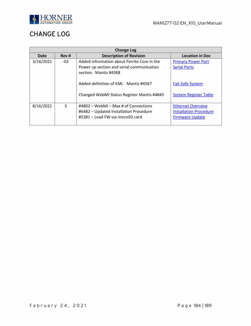
MAN1277-02-EN_X10_UserManual
F e b r u a r y 2 4 , 2 0 2 1 P a g e 184 | 189
CHANGE LOG
Change Log
Date Rev # Description of Revision Location in Doc
3/16/2021 -02 Added information about Ferrite Core in the Power up section and serial communication section. Mantis #4368 Added definition of EMI. Mantis #4567 Changed WebMI Status Register Mantis #4845
Primary Power Port Serial Ports Fail-Safe System System Register Table
8/16/2021 3 #4802 – WebMI – Max # of Connections #6482 – Updated Installation Procedure #5381 – Load FW via microSD card
Ethernet Overview Installation Procedure Firmware Update

MAN1277-02-EN_X10_UserManual
F e b r u a r y 2 4 , 2 0 2 1 P a g e 185 | 189
MAIN INDEX
Add Target Screenshot in Cscape, 65 Alarm Configuration in Cscape, 140 Alarm Object, 137 Alarm Viewer Figure, 138 Alarms, 137 Analog Input Configuration Dialog, 77 Analog Inputs, 92 Analog Output Configuration Dialog, 79 Analog Outputs, 97 ASCII Keypad Figure, 133 ASCII Object, 133 Asynchronous Modes, 104 AutoLoad, 165 AutoLoad Menu, 165 AutoRun, 167 AutoRun Menu, 167 Backup / Restore, 160 Backup / Restore Data, 160 Backup Battery, 178 Backup OCS Data, 161 Backup Registers, 161 Battery backed RAM, 45, 153 Calibrate Analog, 38 Calibrate Analog Inputs, 94 Calibrate Analog Outputs, 94 Calibration, 92 CAN 1 Port Connector, 113 CAN and Termination and Bias, 115 CAN Comm
CAN for I/O Expansion (Network I/O), 115 Cscape Programming, 114 Ladder-Controlled, 114 Overview, 113
CAN COMMUNICATIONS, 113 Clear Backup Data, 163 Clone Unit, 45, 153
Overview, 153 Clone Unit Confirm Screen, 154 Clone Unit Files, 155 Clone Unit Menu after Cloning, 157 Clone Unit Menu before Cloning, 154 Cloning Status, 156 COM, 33, 110, 180 Communicating via MJ1 Serial Port, 68 Communication Configuration Dialog, 66 Communications Port, 63, 64, 180
Compliance, 11 Configuration of a Removable Media, 147 Configuration via Mini-B USB, 112 Configuration--Cscape, 73 Configured reset value, 100 Count, 107 Csape Program
Via Serial Port, 111 Cscape, 57, 60, 61, 67, 110, 135, 145, 147, 180
Analog In Configuration, 77 Analog Out Configuration, 79 Configuration Procedures, 73 Digita In / HSC Configuration, 74 Digital Out / PWM Configuration, 76 Establishing Communications, 61 Overview, 60 Status Bar, 60
Cscape Configuration, 60 Cscape Connection Wizard Screenshots, 62 CscapeStatus Bar, 60 Data Mapping
Update Type, 128 Data Mapping Configuration, 128 Default Gateway, 118 Device Configuration, 126 Device List, 126 Device List and Configuration, 126 Device List and Device Configuration, 126 Device Manager, 180 Devices to Connect to X10, 15 Digital / HSC Input Configuration Dialog, 74 Digital / PWM Output Configuration Dialog,
76 Digital Inputs, 90 Direct digital input control, 100 Direct Digital Input Control, 103 Displaying and entering Data, 131 Downloadable Communication Protocols,
121 Overview, 121
Edit-value mode, 132 ELECTRICAL INSTALLATION, 23 Enable AutoLoad, 44 Enable AutoRun, 43 Ethernet, 61 Ethernet Configuration

MAN1277-02-EN_X10_UserManual
F e b r u a r y 2 4 , 2 0 2 1 P a g e 186 | 189
IP Parameters, 120 Ethernet Module
Default Gateway, 118 IP Address, 118 Net Mask, 118 Status Register, 119 Version Register, 119
Ethernet Module Configuration, 117 Ethernet Module Protocol Configuration,
120 Ethernet Module Protocols & Features, 116 Ethernet Module Protocols and Features,
116 Ethernet Module Specifications, 117 Ethernet System Requirements, 116 Factors Affecting Panel Layout Design and
Clearances, 21 Fail - Safe System
Settings, 160 Fail – Safe System, 42, 159
Overview, 159 Fail – Safe System Menu Figure, 159 Features, 16 Filename Special Symbols Table, 150 Firmware Updates, 172 Flow Chart for AutoLoad, 166 Flow Chart for Automatic Restore, 164 Force and Switch Coils in Ladder
Programming, 135 Frequency, 99 General I/O
Overview, 84 Glossary of High Speed I/O Terms, 98 Ground Specifications, 23 Grounding
Locations of Information, 11 Grounding Definition, 23 High Speed Counter (HSC) Functions, 99 High Speed I/O (HSC/PWM), 98 HSC, 106 HSC Functions Register Map, 58, 106 I/O Status and Calibration, 92 IP Address, 118 Ladder control, 100 Ladder Control, 103 LIMITED WARRANTY, 3 Load Clone, 46, 157 Load Clone Confirm Screen, 158 MAINTENANCE, 172
Make Clone, 153 Marker, 103 Mechanical Installation, 17 microSD Cards, 144
Installing / Removing, 144 microSD File System, 145 Minimum Clearance Requirements for
Panel Box and Door Table, 21 Modbus Addressing Table, 171 Modbus Master, 169 Modbus Master Mapping, 171 Modbus Slave, 168 Model A Digital Output, 86 Model R - Sinking and Sourcing Outputs, 89 Model R and A Digital Input, 91 Model R Relay and Digital Output, 87 Mounting Clip Locations, 18 Mounting Overview, 17 Mounting Requirements, 17 Net Mask, 118 Network Configuration, 124 New-value mode, 132 Numeric keypad, 132 Numeric Object, 132 Opening Cscape Help File, 170 Orientation of X10 OCS, 18 Overview
Modbus, 168 Panel Box
Grounding, 21 Noise, 22 Shock and Vibration, 22 Temperature, 22
Panel Box Clearance, 21 Panel Cutout, 19 Panel Design Checklist, 22 Password Object, 132 Period Falling Edges, 101 Period Rising Edges, 101 Polled Read, 128 Polled Read/Write, 128 Polled Read/Write/Init, 129 Positive and Negative Inputs, 90 PROGRAMMING EXAMPLES, 3 Protocol Config, 123 Pulse, 101
Period Falling Edges, 101 Period Rising Edges, 101 Width Low, 101

MAN1277-02-EN_X10_UserManual
F e b r u a r y 2 4 , 2 0 2 1 P a g e 187 | 189
Pulse Wide Modulation Functions, 106 PWM, 109
Registers, 109 PWM Function Registers Map, 58 PWM, two parameters, Duty Cycle &
Frequency, 107 Quadrature, 102
Configured Counts per Rev Value, 103 References / Useful documents, 16 Register Map for X10 I/O, 58 Registers
%S / %SR, 49 Definitions, 49 I/O, 58 Resource Limits, 59
Relay Outputs, 88 Removable Media, 41, 141
Load / Save Applications, 146, 148, 150, 151
Log Data, 146 Overview, 144 View / Capture, 147
Removable Media (RM) Features— Program Features, 149
Removable Media (RM) Features—Graphic/Screen Editor, 149
Removable Media Features—Additional Configuration, 149
Removable Media Manager, 145 Removable Media Manager Submenu
Figure, 145 Removable Media Object Figure, 141 Removable media viewer Figure, 141 Restore OCS Data, 162 RM Status Values Table, 151 RS-485 Termination, 111 RTD Wiring, 96 Safe Removal of Removable Media Card,
152 Safe Removal of Removable Media Figure,
142 Safety Warning, Guidelines, 10 Scan List, 127 Scan List Entry, 128 Screen Navigation, 134 Screen Saver, 143 Serial Comm
Cscape Programming, 111 Ladder-Controlled, 112
Overview, 110 Ports, 110
SERIAL COMMUNICATIONS, 110 Set Beeper, 39 Set Fkeys, 35 Set Network, 29 Set Network Baud, 30 Set Screen, 40 Set Serial Ports, 36 Set Time/Date, 37 Solid-State Digital Outputs, 85 Sub-Menus, 26 Support Files Website, 61 Synchronous Modes, 104 System Menu
Navigate / Edit, 28 System Menu Figure, 27 Sytem Menu
Overview, 26 Table 06.6 - PWM Functions Register Map,
58 TABLE OF CONTENTS, 5 Target ID, 67, 68 Target indicator, 67 Technical Support, 2, 168, 179
Contacts, 183 Testing for Good Ground, 24 Text Table Object, 133 Time/Date Object, 133 TMJ1/MJ2 Serial Ports, 110 Totalize, 100 Touch (Slip) Sensitivity, 136 Touch Screen Calibration, 47 Triggered Read, 129 Triggered Write, 129 Troubleshooting, 168, 179
Connecting Checklist, 180 Connecting to X10, 179 CsCAN Checklist, 182 CsCAN Network, 181 Local Controller and Local I/O, 181
Troubleshooting Checklist (serial port – MJ1) Programming, 180
Troubleshooting Checklist (USB Port - Mini B) Programming, 180
Two-Point Ground Connection Test Figure, 24
Types of Registers found in the X10 OCS, 49

MAN1277-02-EN_X10_UserManual
F e b r u a r y 2 4 , 2 0 2 1 P a g e 188 | 189
Typical Screen Jump Objects (X10) Figure, 134
USB, 61, 62, 180 USB mini B Port Programming Connector,
61 User Interface, 130
Ladder Based Navigation, 135 Screen Navigation, 134
Using Removable Media to View and Capture Screens, 147
View Diags, 32
View Protocols, 34 View Status, 31 Visual Map, 4 Visual Overview of X10 Connectivity, 15 Where to Find Information about the X10,
14 Wiring—MJ1/MJ2 Serial Ports, 110 X10 OCS Mounting Orientation, 18 X10 OCS with Mounting Clips, 18 X10 Preface, 2

MAN1277-02-EN_X10_UserManual
F e b r u a r y 2 4 , 2 0 2 1 P a g e 189 | 189