user manual guide d’utilisation ... - ridebionx.com · • dc output: default 6v (adjustable from...
TRANSCRIPT
USER MANUALGUIDE D’UTILISATIONBENUTZERINFORMATION
2 3
Welcome
Thank you for choosing BionX™. It is our goal to provide you with the highest quality electric propulsion systems available, and offer you the best possible after sales experience.
This document serves as a supplement to your bicycle user manual. Please read this manual thoroughly, even if you are an experienced cyclist. Should you be unable to find an answer in the manual, please contact your dealer for immediate assistance.
We have always believed that a bike should remain a bike. It is our love of cycling that drives us, and a passion that we continue to share with our customers. We hope you enjoy your new electrically assisted bicycle for many years to come.
If you ever have concerns or questions that your dealer cannot provide answers to, or have comments relating to this user manual, feel free to contact us in Europe at [email protected], in North America at [email protected], and anywhere else in the world at [email protected]
eng
lish
eng
lish

4 5
Table of Contents
User Precautions 4
Description of the BionX D-Series System 6
Description of the BionX S-Series System 8
Description of the BionX P-Series System 10
Inserting or Removing the DS3 Display 12
Inserting or Removing the Console 13
Inserting or Removing the Battery 14
Handling and Charging the Battery 15
Power Supply 17
Assist Mode / Generate Mode / Mountain Mode (where applicable) 18
Operating the BionX Propulsion System 19
Programming the Basic Settings 24
Removing and Installing the Rear Wheel 25
Maintenance and Care 26
Optimizing the Range of the Battery 27
Cleaning 28
Transporting an Electric Bicycle 28
Repair and Spare Parts 28
Troubleshooting 29
Warranty Information and Guarantee 30
User Precautions
We want you to have a fun ride, but also a safe one. Carefully read the following information, even if you are an experienced rider. Take the opportunity to familiarize yourself with your BionX electric propulsion system before you take your first trip.
1. BionX recommends that you have your system installed professionally by an authorized dealer. 2. Read all of the enclosed installation and operating instructions from the manufacturer
and follow the instructions, if any, prior to its first use. 3. Familiarize yourself with your electric bicycle and the functions of the BionX system in a safe
environment before participating in road traffic for the first time. 4. Always wear a helmet when riding an electric bicycle for your own safety. In some jurisdictions,
this is the law.5. Make sure that the tires have the pressure recommended by the manufacturer before riding the bike.6. Make sure that the brakes are operating properly before riding the bike.7. Do not use a mobile phone or any other electronic devices while riding an electric bicycle; it is
imperative that you pay attention to traffic. 8. If possible, ride in bike lanes and always in the correct direction of traffic. 9. Adhere to all valid traffic regulations.10. Keep in mind that other traffic participants may underestimate the speed of an electric bicycle.11. Ride with both hands on the handlebars when riding your electric bicycle.12. Ride as defensively as possible.
Enjoy your new BionX electric propulsion system!
Your BionX Team
NOTE The parts shown in the BionX User Manual are for reference only, the parts included with your BionX system may differ from those shown. More detailed information can be ob-tained from your BionX dealer by request.
eng
lish
eng
lish

6 7
4
2
1
3
Description of the BionX D-Series System 3 D-Series Motor• DC rear hub motor• Power – (nom.) 200W (AU & UK), 250W (EU), 500W
(NA)• Torque – (nom./max.) 25Nm/50Nm (18.4/37lb-ft)• Weight – 4.0kg (8.8lb)• Brushless, gearless• Generate mode for energy recuperation• Integrated torque sensor• 8, 9, and 10 speed cassette compatible
4 Brake switch• A surface mounted reed switch and magnet –
connected to the BionX console• Upon brake application, assistance is shut off
(“kill switch”) and Generate mode is activated
Power Supply• Power supply to recharge the 48V Li-Ion battery • Input voltage: 100-240V • Output voltage: 26V• Max. charge current: 3.45A• Output: 90W
1 RC3 Controller and (optional) DS3 Display • Removable colour DS3 display console• 4 Assistance levels• 4 Generate levels • RC3 with system controls, battery state-of-charge indicator• Offers cyclecomputer functions (speed, odometer,
clock, average speed, trip distance)
G2 Console• Removable G2 console• Illuminated LCD display with battery state-of-charge• 4 Assistance levels• 4 Generate levels• Backlight, and bicycle light controls (if applicable)• Offers cycle computer functions (speed, odometer,
clock, average speed, trip distance)
Remote throttle (where applicable)• Assistance/Generate toggle• Variable control throttle lever
2 48V Down Tube Battery• Lithium Ion (Li-Ion)• Removable, lockable• TOUCH PORT state-of-charge indicator• DV – 48V / 11.6Ah / 555Wh • DC Output: Default 6V (adjustable from 6V to 12V
where applicable). Maximum current: 1.5A Connector: Type Jack 2.1mm
eng
lish
eng
lish
8 9
4
2a
1
3
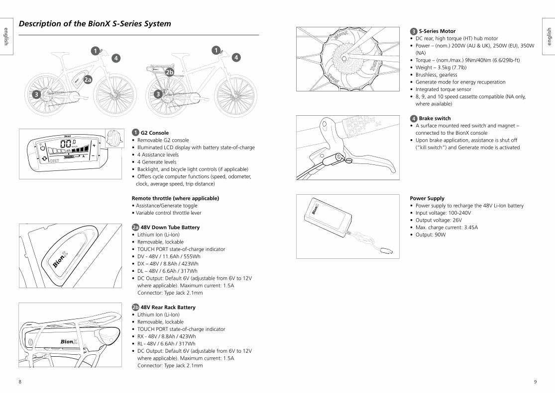
Description of the BionX S-Series System3 S-Series Motor
• DC rear, high torque (HT) hub motor• Power – (nom.) 200W (AU & UK), 250W (EU), 350W
(NA)• Torque – (nom./max.) 9Nm/40Nm (6.6/29lb-ft)• Weight – 3.5kg (7.7lb)• Brushless, gearless• Generate mode for energy recuperation• Integrated torque sensor• 8, 9, and 10 speed cassette compatible (NA only,
where available)
4 Brake switch• A surface mounted reed switch and magnet –
connected to the BionX console• Upon brake application, assistance is shut off
(“kill switch”) and Generate mode is activated
Power Supply• Power supply to recharge the 48V Li-Ion battery • Input voltage: 100-240V • Output voltage: 26V• Max. charge current: 3.45A• Output: 90W
1 G2 Console• Removable G2 console• Illuminated LCD display with battery state-of-charge• 4 Assistance levels• 4 Generate levels• Backlight, and bicycle light controls (if applicable)• Offers cycle computer functions (speed, odometer,
clock, average speed, trip distance)
Remote throttle (where applicable)• Assistance/Generate toggle• Variable control throttle lever
2a 48V Down Tube Battery• Lithium Ion (Li-Ion)• Removable, lockable• TOUCH PORT state-of-charge indicator• DV - 48V / 11.6Ah / 555Wh• DX – 48V / 8.8Ah / 423Wh • DL – 48V / 6.6Ah / 317Wh• DC Output: Default 6V (adjustable from 6V to 12V
where applicable). Maximum current: 1.5A Connector: Type Jack 2.1mm
2b 48V Rear Rack Battery• Lithium Ion (Li-Ion)• Removable, lockable • TOUCH PORT state-of-charge indicator• RX - 48V / 8.8Ah / 423Wh• RL - 48V / 6.6Ah / 317Wh• DC Output: Default 6V (adjustable from 6V to 12V
where applicable). Maximum current: 1.5A Connector: Type Jack 2.1mm
2b
3
14
eng
lish
eng
lish
10 11
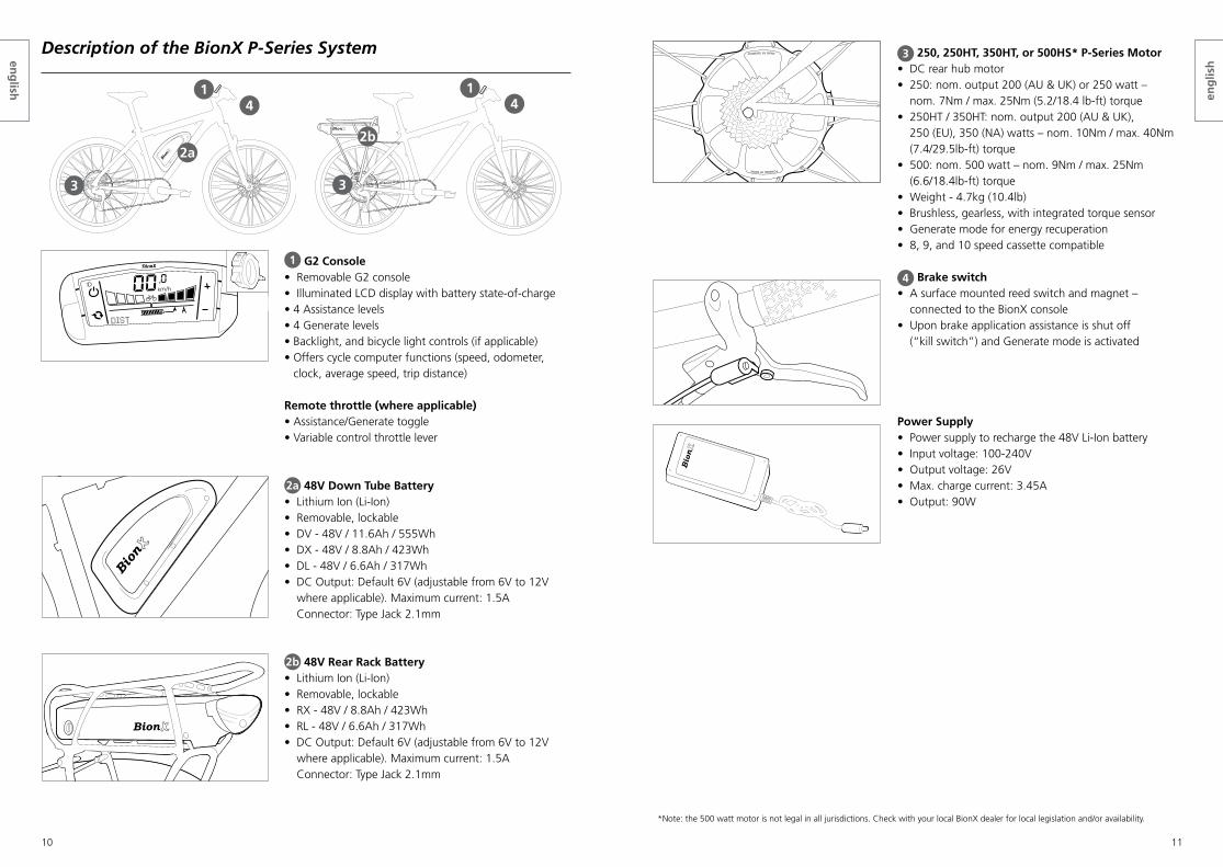
Description of the BionX P-Series System
1 G2 Console• Removable G2 console• Illuminated LCD display with battery state-of-charge• 4 Assistance levels• 4 Generate levels • Backlight, and bicycle light controls (if applicable)• Offers cycle computer functions (speed, odometer,
clock, average speed, trip distance)
Remote throttle (where applicable)• Assistance/Generate toggle• Variable control throttle lever
2a 48V Down Tube Battery• Lithium Ion (Li-Ion)• Removable, lockable • DV - 48V / 11.6Ah / 555Wh• DX - 48V / 8.8Ah / 423Wh• DL - 48V / 6.6Ah / 317Wh• DC Output: Default 6V (adjustable from 6V to 12V
where applicable). Maximum current: 1.5A Connector: Type Jack 2.1mm
2b 48V Rear Rack Battery• Lithium Ion (Li-Ion)• Removable, lockable• RX - 48V / 8.8Ah / 423Wh• RL - 48V / 6.6Ah / 317Wh• DC Output: Default 6V (adjustable from 6V to 12V
where applicable). Maximum current: 1.5A Connector: Type Jack 2.1mm
4
2a
1
3
2b
3
14
3 250, 250HT, 350HT, or 500HS* P-Series Motor• DC rear hub motor• 250: nom. output 200 (AU & UK) or 250 watt –
nom. 7Nm / max. 25Nm (5.2/18.4 lb-ft) torque• 250HT / 350HT: nom. output 200 (AU & UK),
250 (EU), 350 (NA) watts – nom. 10Nm / max. 40Nm (7.4/29.5lb-ft) torque
• 500: nom. 500 watt – nom. 9Nm / max. 25Nm (6.6/18.4lb-ft) torque
• Weight - 4.7kg (10.4lb)• Brushless, gearless, with integrated torque sensor• Generate mode for energy recuperation • 8, 9, and 10 speed cassette compatible
4 Brake switch• A surface mounted reed switch and magnet –
connected to the BionX console• Upon brake application assistance is shut off
(“kill switch”) and Generate mode is activated
Power Supply• Power supply to recharge the 48V Li-Ion battery • Input voltage: 100-240V • Output voltage: 26V• Max. charge current: 3.45A• Output: 90W
*Note: the 500 watt motor is not legal in all jurisdictions. Check with your local BionX dealer for local legislation and/or availability.
POWERED BY BIONX
POWERED BY BIONX
ELECTRIC SERIES
1
2
34
ODO
eng
lish
eng
lish

12 13
Inserting or Removing the Console
Inserting the console • Slide the console into the console mount on the handlebar• Make sure that the console engages securely. When inserted correctly, you will hear a “click”
Removing the console • Release the console by pushing the release lever on the console mount• Slide the console out of the console mount
Center mount• Available option for all BionX systems• To be used with regular receptacle, replaces standard mounting
kit (clip & rubber)
“click”
WARNING Never unplug any connection with the system turned on - this includes the console. Pulling a live part can render it inoperable!
Inserting or Removing the DS3 Display
Inserting the DS3 • Turn the system off via the RC3 controller (no illustration)• Place the DS3 on the display dock turned 90° to the left• Rotate the DS3 90° to the right and the DS3 is locked in place
Removing the DS3 • Turn off the system via the RC3 controller (no illustration)• Rotate the DS3 90° to the left, it will pop loose• Lift the DS3 up to remove
WARNING Never unplug any connection with the system turned on - this includes the DS3 display. Pulling a live part can render it inoperable!
CLICK
00ODOMETER
.0
1234.5 km
km/h00
ODOMETER
.0
1234.5 km
km/h
eng
lish
eng
lish

14 15
Inserting the rear rack battery:1 Open the lock cylinder: please ensure that the key is removed from the lock cylinder2 Place the battery onto the battery docking station3 Gently push the battery in a forward direction, towards the battery connector
Make sure the battery is inserted all the way, flush with the docking station cover4 Push in the lock cylinder until a ‘click’ is heard
Removing of the rear rack battery:1 Turn off the system via the console (no illustration)2 Turn the key in the lock cylinder until it pops out3 Remove the key from the lock cylinder4 Pull the battery backwards, along the battery rail
Handling and Charging the Battery
WARNING BionX batteries shall only be recharged with BionX chargers or BionX power supplies. The use of other power supplies/chargers can damage the battery. Never short circuit the bat-tery by connecting the contacts of the battery. Never open the battery, as this could dam-age the battery and possibly lead to overheating. The battery cannot be serviced by the user. Opening the battery case voids all warranty and product liability claims. Never use a battery which has obvious damage to the case(s) or the battery connector.
001
001
001
001
001
2
3 4
WARNING Do not force the battery onto the battery docking station. This can damage the battery connector, or damage the rear light. Never unplug any connection with the system turned on - this includes the battery. Pulling a live part can render it inoperable! If a battery is re-moved while the system is turned on, wait 5 minutes until it turns off before re-installing. A series of 5 beeps will indicate the battery has shut off and it is safe to install again.
001
001
001
001
1” (25.4mm
)
001
CLICK
1
2
3
4
Inserting or Removing the Battery
Inserting the down tube battery 1 Place the battery onto the docking station 2 Slide the battery down the rail gently towards the connector 3 The release arm will begin to move to the closed position as the battery slides towards the connector4 When the release arm is almost closed, hold it in place and simultaneously push in the lock cylinder –
you will hear a “click” when the lock cylinder is properly closed
Removing the down tube battery1 Turn off the BionX propulsion system via the console (no illustration)2 Lightly press on the battery release arm, insert the key and turn clockwise
The lock cylinder will pop out, freeing the battery release arm3 Remove the battery by opening the release arm 4 Slide the battery upwards on the rail5 Lift the battery to remove
25.4mm
(1”)
001
001
25.4mm
(1”)
001
001
1” (25.4mm
)
001
001
2
3
4
5
WARNING Do not force the battery release arm closed, or force the battery onto the battery dock. This can damage the battery connector. Never unplug any connection with the system turned on - this includes the battery. Pulling a live part can render it inoperable! If a bat-tery is removed while the system is turned on, wait 5 minutes until it turns off before re-installing. A series of 5 beeps will indicate the battery has shut off and it is safe to install again.
25.4mm
(1”)
001
001
25.4mm
(1”)
001
001
25.4mm
(1”)
001
001
1
2 3
1” (25.4mm
)
001
001
“click”
4
eng
lish
eng
lish

16 17
Power Supply
48V battery charging procedure (power supply)• Connect the power supply and the battery by
inserting the charge connector into the TOUCH PORT – the BionX system can be on or off
• Connect the power supply to a power receptacle• The battery TOUCH PORT (LED ring around the
charge connector) lights up red upon insertion and then turns to amber during the charging process
• When fully charged, the colour of the LED ring changes to green. The battery charging process is then complete
• Following this procedure the charging connector should be disconnected from the battery• During the charging process you can check the battery state-of-charge through the console if the
battery is connected to the system – a 48V system can be switched on while it is charging
This has my vote :)
Battery state-of-charge Colour
100-75 % Green
75-20 % Amber
< 20 % Red
Checking the 48V Battery state-of-charge• Swipe your finger slowly over the TOUCH PORT• Battery state-of-charge LED will illuminate• Allow ten (10) seconds before checking state-of-charge again
NOTE The power supply is suitable for line voltage ranges of 110-115V or 220-230V, and com-pensates automatically. The 48V battery is designed to be charged by a 26V BionX power supply. The battery has an integrated charger which permits the use of a small, portable power supply.
Ensure that a completely charged battery is no longer connected to the power supply after the charge procedure is completed.
TOUCH PORT green = fully charged
TOUCH PORT amber = charging
TOUCH PORT red = upon insertion
It is best to store the battery in a cool location at temperatures between 10 °C (50 °F) and 25 °C (77 °F). Never store the battery in locations where the temperatures can reach more than 45 °C (113° F) or fall below -10 °C (14 °F). The battery should never be exposed to extreme temperature fluctuations or humidity, and always protect the battery during storage from humidity to prevent corrosion of the connectors. Never drop the battery. Always protect it from physical damage. Damage may lead to short-circuits, and as a result cause overheating of the battery.
Do not dispose of used batteries in regular household trash, be aware that used batteries must be disposed of properly! BionX batteries can be returned to BionX to be recycled.
WARNING The BionX power supply/charger should be used exclusively for BionX rechargeable batteries of the specified type. Keep the power supply or charger away from water or moisture when charging and/or connected to prevent electrical shock or short-circuits.
Do not use a power supply or charger that has obvious signs of damage to the cable, housing, or the connector.
Extreme temperatures will affect battery life, especially during charging. Avoid charging in direct sunlight or in very hot or cold temperatures as this will reduce the life of the battery considerably. We recommend charging the battery at room temperature (approximately 20 °C / 68 °F). The battery should be warmed to room temperature before it is charged, particularly if it was exposed to cold temperatures during a ride. The battery can be charged when mounted on the bicycle or removed from the docking station. A Lithium Ion battery does not have a memory effect, which means that the battery’s maximum energy capacity is not affected if it is repeatedly recharged after only being partially discharged. The battery does not need to be completely drained before charging. We recommend charging the battery after every ride, preferrably when the state-of-charge display shows less than 50%. When the battery is fully depleted it will signal that a recharge is needed by beeping. The battery is fully charged after approximately 4 to 5.5 hours.
CAUTION All classic BionX batteries must be charged when not in use for a long period of time (i.e. before winter storage) and then must be charged at minimum every three months. Not charging the battery can lead to potential damage of the battery cells. This is a lack of maintenance on behalf of the owner, which can incur a loss of warranty.
NOTE New 48V BionX batteries are equipped with “Deep Sleep” mode, a function that preserves battery energy depending on either the state of charge or significant inactivity. A fully charged battery will automatically enter Deep Sleep after 2 months, while a partially discharged battery will enter it in increasingly faster time frames. This results in minimal energy consumption during standby and enables a shelf life of up to 6 months for a fully discharged battery, and up to 18 months for a fully charged battery. To activate a battery that has entered Deep Sleep mode, connect it to the 26V BionX power supply and allow it to complete a full charge cycle. BionX still recommends charging these batteries at minimum every 6 months.
eng
lish
eng
lish

18 19
Assist Mode / Generate Mode / Mountain Mode (where applicable)
The BionX propulsion system offers four levels of assist in the Assistance mode, and four levels of regeneration in the Generate mode. In the Assistance mode, your pedaling is assisted proportionally by an electric motor that drives the rear wheel. A torque sensor is located on the axle of the BionX motor and measures the effort provided by the rider; this produces a natural feeling assistance from the motor. A cadence of roughly 80 RPM is ideal, this allows for effective response from the torque sensor and efficient use of battery energy.
When in Generate mode, the BionX motor functions as a generator and recharges the battery. When going downhill, you can regulate your speed by varying the Generate level. This Generate function provides a level of braking, however it does not replace legally required brakes. If the rear brake lever is pulled, the drive system automatically enters Generate mode. The range can therefore be extended up to 15%, depending upon road conditions.
The Mountain mode uses an intelligent algorithm based upon the effort and the assistance level required.The Mountain mode provides the rider with an assistance level optimized for climbing long steep hills. Without this mode, the motor can automatically revert to an overheat protection mode thereby diminish-ing the assistance provided. Note that level 4 assist is more powerful than Mountain mode.
NOTEIt is recommended that the BionX system should always be turned ON while riding. It allows the rider to use the regenerative braking feature, speedometer and odometer functions. A rider should always remain in control and adjust their speed depending on ter-rain, riding conditions, and their own skill level.
250HT (EU) / 350HT (NA) / D-Series Motor performance
Assistance Mode (A) Level of Assist Riding Situation
1 35% Riding on level ground
2 75% Slight inclines, head wind
3 150% Steep hills, strong head wind
4 300% Very steep roads
250/500 Motor performance
Assistance Mode (A) Level of Assist Riding Situation
1 25% Riding on level ground
2 50% Slight inclines, head wind
3 100% Steep hills, strong head wind
4 200% Very steep roads
Mountain Mode (where available) Long, steep climbs
Generation Mode (G)
1 Slight downhill grade, tailwind
2 Significant downhill grade, tailwind
3 Steep descent
4 Very steep descent
Turn the system onBriefly push , the battery will beep 4 times and the bat-tery LEDs will illuminate. After startup, the system is always in Neutral (N / green LED) mode, indicating no motor assist/normal bicycle operation. To turn the system off, hold
for 4 seconds and the battery will beep 5 times. After 5 minutes of inactivity the system turns off automatically.
Operating the BionX Propulsion System
RC3 Controller
1. On/Off button2. Lights on/off3. Battery state-of-charge indicator4. Neutral/Assist/Generate level5. Assistance toggle (+)6. Left toggle / Select (with DS3 only)7. Right toggle / Scroll (with DS3 only)8. Assistance toggle (-)9. Throttle lever
00ODOMETER
.0
1234.5 km
km/h00
ODOMETER
.0
1234.5 km
km/h
4
2
1
3
5
8
9
6
Select Assistance/Generate levelPush / key for more/less assist (see LEDs 1-4 along left hand side of module). From Neutral (N) push
key to enter continuous Generate mode - the LEDs will flash to indicate Generate mode.
Turn on bicycle light (if applicable)Briefly push key bicycle lights (if available, battery integrated) are turned on.
Turn off bicycle lightBriefly push key again.
Throttle engagementDefault min. 3km/h to engage throttle. Note: throttle control is variable based on lever position.
WARNING Both the RC3 and G2 throttle should be installed in a manner/location where shift lever, brake lever or any other accessory does not at any time affect the proper function and use of the throttle.
7
eng
lish
eng
lish

20 21
Operating the BionX Propulsion System
Turn the system onBriefly push either top button on the console. The battery will beep 4 times and you will see a countdown, this is the system perfoming a self check. After startup, the system is always in mode (no motor assist/bike operation). To turn the system off, briefly push . The battery will beep 5 times. After 5 minutes of “no operation” the system turns off automatically.
Select Assistance/Generate levelPush / key for more/less assist (see bar “fields 1-4” above display “A”). From mode push key to enter continuous Generate mode.
10
9
21
4 3
7
58
6
1. Power2. Key3. Key4. Cycle5. State-of-charge
indicator
6. (bicycle) mode 7. Speedometer8. Trip distance/average speed/
chronometer/odometer/clock9. Assist level (A)10. Generate level (G)11. Wrench symbol
G2 Console
NOTEThe system performs a self check approximately every hour. Do not be alarmed if the system turns itself on briefly, and off again, or if the TOUCH PORT flashes momentarily.
11
Operating the DS3 Display with the RC3 Controller
The DS3 screens shown may vary slightly depending on which version you have selected to view.
00ODOMETER
.0
1234.5 km
km/h
00.0km/h
ODOMETER1234.5 km
TRIP0.5 km
1. Assist / Generate level indicator2. Light indicator3. Power / Generate meter4. Speedometer5. Battery state-of-charge indicator6. Cyclecomputer function
Select Assistance/Generate levelPush / buttons on the RC3 to adjust assistance / generate levels. From Neutral (N, green LED) push key to enter continuous Generate mode.
Toggle Cyclecomputer Functions Briefly push left and right toggle to display Odom-eter, Trip Distance, Trip Time, Average Speed, Clock and Settings. To reset Trip Distance, Trip Time, and Average Speed, press and hold the left toggle (Select) for 3 seconds.
Toggle Display Screen Type Hold right toggle (Scroll) for 3 seconds to alternate display between Simple, Enhanced, or Technical screens. The default screen at startup can be altered in the Settings Menu.
00ODOMETER
.0
1234.5 km
km/h
00.0km/h
ODOMETER1234.5 km
TRIP0.5 km
00ODOMETER
.0
1234.5 km
km/h
00.0km/h
ODOMETER1234.5 km
TRIP0.5 km
4
2
1
3
5
6
eng
lish
eng
lish
22 23
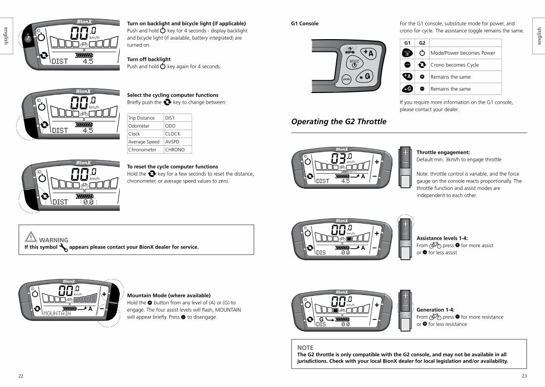
Turn on backlight and bicycle light (if applicable)Push and hold key for 4 seconds - display backlight and bicycle light (if available, battery integrated) are turned on.
Turn off backlightPush and hold key again for 4 seconds.
Select the cycling computer functionsBriefly push the key to change between:
Trip Distance DIST
Odometer ODO
Clock CLOCK
Average Speed AVSPD
Chronometer CHRONO
To reset the cycle computer functionsHold the key for a few seconds to reset the distance, chronometer, or average speed values to zero.
4s
WARNING If this symbol appears please contact your BionX dealer for service.
Mountain Mode (where available)Hold the button from any level of (A) or (G) to engage. The four assist levels will flash, MOUNTAIN will appear briefly. Press to disengage.
12
34
Operating the G2 Throttle
Throttle engagement:Default min. 3km/h to engage throttle
Note: throttle control is variable, and the force gauge on the console reacts proportionally. The throttle function and assist modes are
independent to each other.
Assistance levels 1-4:From press for more assist or for less assist
Generation 1-4:From press for more resistance or for less resistance
NOTEThe G2 throttle is only compatible with the G2 console, and may not be available in all jurisdictions. Check with your local BionX dealer for local legislation and/or availability.
G1 Console For the G1 console, substitute mode for power, and crono for cycle. The assistance toggle remains the same.
G1 G2
Mode/Power becomes Power
Crono becomes Cycle
Remains the same
Remains the same
If you require more information on the G1 console, please contact your dealer.
eng
lish
eng
lish

24 25
Programming the Basic Settings
In general, all settings of your BionX electric propulsion system are pre-set. Basic display functions can be set by entering the programming mode. Contact your dealer to customize the advanced functions of your system.
Go to the Settings screen for the DS3 Display/RC3 ControllerScroll through the cyclecomputer functions with the left or right toggle buttons until the display shows “Settings”. Cycle the menus / values with or and confirm with the left toggle (Select) button. Move back a menu with the right toggle (Scroll) button.
Turn on the programming mode for the G2 consoleSimultaneously push and until the display shows “0000”. The first zero blinks. Change the value of the selection with or and confirm with . Select the other digits in the same manner until the desired program is displayed.
Note: For G1 programming, substitute (mode) and (crono) for (power) and (cycle) respectively, and remain the same.
Code Description
2001 Select km/h or mph
2002 Regeneration/brake output (for reed switch) 0-40 (ideally 30-40)
2004 Clock adjust
2005 Tire circumference (millimeters)
2009 Flip Display: 0 = power left, 1 = power right (G2 only)
Code 2001 Code 2002 Code 2004
Select unit - km/h or mph. Select with or , and confirm with .
Default value: 30. Change with and . Confirm with .
Select hour/minutes with , change value with and . Confirm with .
Code 2005 Code 2009Set tire size (in mm) - Select digits one after another with or , and confirm with .
Current setting of main functions is displayed. Flip = 0, assist toggle is on the right side of console; Flip = 1, assist toggle is on the left side of console. Confirm with .
WARNING Do not use other programming codes without consulting your authorized dealer. If you type the wrong code, please push the key to exit programming mode.
Removing and Installing the Rear Wheel
We recommend the removal and installation of the rear wheel to be done by a qualified dealer. Should you have to do this yourself, please follow the instructions below:
To remove the rear wheel1 Make sure that the system is turned off via the console (no illustration)2 Remove the neoprene covers (if applicable)3 Disconnect the two cable connections that lead to the motor (COMMUNICATION A , before POWER B ) 4 Disconnect the cable guide from the rear wheel brake (only on bicycles with rim brakes, not shown)5 Loosen the axle nut on the rear wheel using a 15mm wrench6 Slide the rear wheel downwards, out of the dropout
WARNING Always turn off the propulsion system prior to connecting or disconnecting the motor cables.
CAUTION It is essential that the axle nuts are tightened to 40Nm (30lb-ft); this assures that the propulsion system functions properly. Ensure the torque reaction collar is fully inserted into the dropout. The notch on the non-drive side must also be facing in the direction of 6 o’clock (within 5° either way). If this notch placement is incorrect, please consult your dealer.
If your bike is equipped with hydraulic disc brakes: Do not pull the brake lever with the brake disc on the rear wheel removed from the caliper. Insertion of the wheel can be difficult or impossible as the brake pads will prevent the brake disc from sliding in place.
15m
m
15mm
40Nm(30lb-ft)
15m
m
15mm
40Nm(30lb-ft)40Nm
15m
m
15mm
32
5
6
B
A
eng
lish
eng
lish
26 27
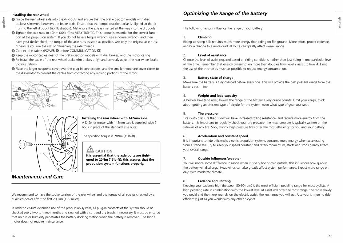
Installing the rear wheel1 Guide the rear wheel axle into the dropouts and ensure that the brake disc (on models with disc
brakes) is inserted between the brake pads. Ensure that the torque reaction collar is aligned so that it fits into the left dropout (no illustration). Make sure the axle is inserted all the way into the dropouts
2 Tighten the axle nuts to 40Nm (30lb-ft) (= VERY TIGHT!). This torque is essential for the correct func-tion of the propulsion system. If you do not have a torque wrench, use a normal wrench, and then have your dealer check the torque of the axle nuts as soon as possible. Use only the original axle nuts; otherwise you run the risk of damaging the axle threads
3 Connect the cables (POWER A before COMMUNICATION B ) 4 Keep the motor cables clear of the brake disc (on models with disc brakes) and the motor casing5 Re-install the cable of the rear wheel brake (rim brakes only), and correctly adjust the rear wheel brake
(no illustration)6 Place the larger neoprene cover over the plug-in connections, and the smaller neoprene cover closer to
the disc/motor to prevent the cables from contacting any moving portions of the motor
00ODOMETER
.0
1234.5 km
km/h
00.0km/h
ODOMETER1234.5 km
TRIP0.5 km
Installing the rear wheel with 142mm axleA D-Series motor with 142mm axle is supplied with 2 bolts in place of the standard axle nuts.
The specified torque is 20Nm (15lb-ft).
Maintenance and Care
We recommend to have the spoke tension of the rear wheel and the torque of all screws checked by a qualified dealer after the first 200km (125 miles).
In order to ensure extended use of the propulsion system, all plug-in contacts of the system should be checked every two to three months and cleaned with a soft and dry brush, if necessary. It must be ensured that no dirt or humidity penetrates the battery docking station when the battery is removed. The BionX motor does not require maintenance.
15m
m
15mm
40Nm(30lb-ft)
15m
m
15mm
40Nm(30lb-ft)
15m
m
15mm
40Nm(30lb-ft)
A
B2
3
4
6
Optimizing the Range of the Battery
The following factors influence the range of your battery:
1. Climbing Riding up steep hills requires much more energy than riding on flat ground. More effort, proper cadence, and/or a change to a more gradual route can greatly affect overall range.
2. Level of assistance Choose the level of assist required based on riding conditions, rather than just riding in one particular level all the time. Remember that energy consumption more than doubles from level 2 assist to level 4. Limit the use of the throttle as much as possible to reduce energy consumption.
3. Battery state of charge Make sure the battery is fully charged before every ride. This will provide the best possible range from the battery each time.
4. Weight and load capacity A heavier bike (and rider) lowers the range of the battery. Every ounce counts! Limit your cargo, think about getting an efficient type of bicycle for the system, even what type of gear you wear.
5. Tire pressure Tires with pressure that is low will have increased rolling resistance, and require more energy from the battery. It is important to regularly check your tire pressure, the max. pressure is typically written on the sidewall of any tire. Slick, skinny, high pressure tires offer the most efficiency for you and your battery.
6. Acceleration and constant speedIt is important to ride efficiently; electric propulsion systems consume more energy when accelerating from a stand still. Try to keep your speed constant and retain momentum, starts and stops greatly affect your overall range.
7. Outside influences/weather You will notice some difference in range when it is very hot or cold outside, this influences how quickly the battery will discharge. Headwinds can also greatly affect system performance. Expect more range on days with moderate climate.
8. Cadence and Shifting Keeping your cadence high (between 80-90 rpm) is the most efficient pedaling range for most cyclists. A high pedaling rate in combination with the lowest level of assist will offer the most range, the more slowly you pedal and the more you rely on the electric assist, the less range you will get. Use your shifters to ride efficiently, just as you would with any other bicycle!
CAUTION It is essential that the axle bolts are tight-ened to 20Nm (15lb-ft); this assures that the propulsion system functions properly.
eng
lish
eng
lish
28 29
Cleaning
CAUTION Never use a high pressure washer or a garden hose to clean the propulsion system. The force of a water jet could damage the electrical components of the propulsion system.
We recommend a soft sponge or a soft brush to clean the bicycle. Use a moist rag to clean the battery docking station. Always use very little water, and keep water away from the electrical contacts. Check the plug-in connections for moisture after cleaning and let these dry, if necessary, before using the bicycle.
Transporting an Electric Bicycle
WARNING Make absolutely certain that the bike rack on your car is suitable for the increased weight and the unique frame style of your electric bicycle. A rack that is not suitable can be damaged or even break during the transport of the electric bicycle. The electric bicycle can be damaged by an unsuitable bike rack.
When transporting a BionX equipped bicycle on a bike rack, always remove the battery and the console. In case of inclement weather, your motor and system connections should be protected from the elements. When travelling by air, it is important to understand that a lithium battery is classified as dangerous goods and must be transported by a qualified handler. Your battery cannot accompany you and your bicycle on a commercial flight.
Repair and Spare Parts
WARNING The use of spare parts from unknown sources, for example replacement parts from third parties, as well as opening the battery or replacing the cellpack is strictly prohibited.
For repair of your electric bicycle, consult a qualified dealer. The use of spare parts from unknown sources, for example, replacement parts from third parties, is strictly prohibited. If you need spare keys for the battery, please contact a BionX dealer. Please retain the key number for your records. It is located on the battery key, as well as on the face of the battery lock cylinder. If you are dropping off your bicycle for a tune up or repair, always bring your battery keys to the dealer.
BionX Key Number
115
FUSE
This notch is very important
Troubleshooting
The system does not turn onCheck the battery and make sure that it is charged. The battery must be correctly inserted onto the docking station and the lock must be completely closed. Also check that all connectors of the wiring harness are properly engaged, and the console is inserted properly. If the problem persists, contact an authorized dealer.
The system can be turned on but there is no assist / POWER PROT appears on console screen / RC3 Controller LED lights are cascading Check all connections, in particular that the cables running from the battery to the motor are properly connected (with the system turned off). Turn the system on. If the problem persists, contact your dealer.
The system is continuously in Generate modeWhen the propulsion system is continuously in Generate mode and cannot be switched back to assist mode by pushing the key, the problem most likely lies with the brake switch that is located under the brake lever. In this case try to “repair” the system by turning it off and then on again. If that does not solve the problem, you can temporarily bypass it by removing the plug-in connection from the console to the brake switch.
WARNING If you bypass the brake switch you also disable regenerative braking, in doing so your BionX system will not provide any additional braking. We recommend that you contact a dealer as soon as possible.
The motor is not as powerful after a repair or serviceTighten the nuts of the rear axle to the specified torque (40Nm/30lb-ft); check that the axle slot is facing in the direction of 6 o’clock. If the problem persists, contact an authorized dealer.
The battery state-of-charge display on the console does not show “full” after a complete charging procedureMake sure that you have followed all of the instructions for the charging procedure. Let the battery cool off for a few hours and charge it again. If the gauge still does not indicate a full charge, let the battery cool again, fully deplete the battery and charge it again. If the problem persists, contact an authorized dealer.
The throttle lever offers no responseCheck the throttle connections. Next, attempt to calibrate the throttle, hold the and buttons until a countdown begins at the top of the console screen. Fully depress the throttle lever and release a few times during the countdown. The system will not turn on after storage48V BionX batteries are now equipped with “Deep Sleep” mode, a new function that preserves battery energy. To activate a battery that has entered Deep Sleep mode, connect it to the 26V BionX power sup-ply. If the battery is removed from the system when doing so, allow the battery 5 minutes until it turns off before re-installing. A series of 5 beeps will indicate the battery has shut off and it is safe to install again.
eng
lish
eng
lish

30 31
The console/display shows ACTIVATE IN XXkm or the green neutral LED on the RC3 is blinking continuouslyAll new BionX systems are shipped in demo mode and require activation by an authorized dealer. If you see this message or LED notification, please return to your dealer so they can activate your system.
Warranty Information and Guarantee
The BionX warranty covers a two (2) year period for all parts of the BionX propulsion systems to the first owner within the framework of the following conditions:
1. This warranty exclusively covers systems provided by BionX excluding all the other bicycle components provided by other bicycle manufacturers.
2. This warranty covers the repair and/or the replacement of BionX propulsion systems provided that the equipment concerned loses its functionality within the agreed warranty period and also provided that the claim is not related to any of the following cases expressly excluded under this warranty.
3. Any other legal provisions, particularly with respect to warranty regulations, are not restricted by this warranty.
4. This warranty only covers material and manufacturing defects. It is only effective with a valid proof of purchase consisting of the original purchase document or receipt indicating the date of purchase, the serial number, the dealer’s name and the designation of the system model. BionX reserves the right to reject the coverage of this warranty if the accompanying documentation of BionX components is not accurate or complete.
5. In the case of a warranty claim, BionX undertakes to either repair faulty system components and/or to replace such components, at BionX discretion (Service Replacement Unit).
6. Warranty repairs have to be exclusively performed by BionX. Any component to be repaired under the framework of this warranty has to be transferred to the dealer at the client’s own expenses and risks, and, after the completion of such repair, has to be picked up at the dealer. In the case of rightful warranty claims, BionX reserves the right to bear or repay transportation expenses. In order to have a previous determination whether a warranty claim is justified or not, the end user has to submit his claim to the dealer from whom he purchased the product so that the respective dealer handles the shipment to BionX.
7. Costs for repair work performed in advance by persons who have not been authorized by BionX will not be reimbursed. In such a case, any warranty claim will cease.
8. Repair work and/or replacement of components during the warranty period does not lead to an extension and/or a new start of the warranty period. Repair work and direct replacement during the warranty period may be performed with functional replacement components of equal value.
9. The two-year warranty period starts with the date of purchase. Warranty claims must be reported immediately.
10. If the battery/cell pack does not provide full capacity in the course of normal use or for batteries going through a normal aging process or reduction of performance, BionX warranty only covers that within the two-year warranty period or within 500 charging cycles, whichever event occurs first, to the condi-tion that the battery provides less than 70% of its initial capacity.
11. No warranty claims are accepted – without limitation to other reasons – in the case of damages due to the following: a) External influences, particularly falling rocks, collision, accident and other external events with an immediate external effect due to mechanical powers. b) Purposeful and/or malevolent acts, theft and robbery as well as natural hazard events and/or acts of mischief. c) Inappropriate use, e.g. the product was exposed to liquids, chemicals of any type and/or extreme temperatures, wetness and humidity and/or if the battery suffers damages due to non-compliance with the special instructions set forth in the chapter “Handling and Charging of the Battery“as specified in the BionX User Manual d) Overcharging the battery or not adhering to the instructions of battery handling. e) Abuse/mis-handling of the connectors f) In the case of malfunctioning internal and/or external components due to impact caused by drop- ping a part on the ground. g) If the motor axle nut has been over tightened / improperly installed to the point where the threads of the axle have been damaged. h) If the maximum weight on the bicycle (specifically – bicycle, rider, AND load) has been over 150kg. i) If the functionality of the Touch Port feature is intermittent; this is a redundancy of the state of charge indicator that is available on the console.
12. No warranty claims are accepted - without limitation to other reasons: a) In the case of test, maintenance, repair and replacement work due to normal use. b) If the model, serial or product number on BionX product has been changed, deleted, blurred or removed. The seal and/or the serial number decal on the battery housing has been broken or obviously manipulated. c) In the case of use of the battery in systems that are not approved for such use with this particular product. d) In the case of the operation of the BionX system with batteries other than the batteries designed for the BionX system (refer to user manual). e) If one or more than one BionX part has been opened, altered or repainted. f) The bike has been used for rental or commercial application.
13. This warranty only covers the above mentioned repair work and/or the replacement of defective or compromised components. It excludes any claims as to the reimbursement of property damages, downtimes, expenses for renting or leasing equipment, travel expenses, lost profit or any other claims. BionX liability in connection with this warranty is limited to the respective acquisition value of the product.
14. This warranty only covers original BionX components. The use of spare parts from unknown sources, for example, replacement parts from third parties, is strictly prohibited.
15. Warranty will be voided on any system on which it will be concluded that there has been any case of modification or tampering with firmware.
eng
lish
eng
lish

32 33
BionX, BionX Design and powered by BionX are trademarksof BionX International Corporation.
©2016 BionX International Corporation. All Rights Reserved.01-4646 EN REVISION C
16. One (1) additional year of warranty is provided free of charge on BionX systems starting from MY2016if:a) The bicycle has been registered on the date of purchase (or up to 90 days after system activation)
through the email link sent by BionX by providing the following requested information:• Name• Address• Phone number• Email• Additional survey information
*** Please note that a false declaration will automatically void the extra year of warranty b) The bicycle has been inspected and the software has been updated using the BBI at least once
every year (12 months) after the date of registration by an approved BionX dealer.c) If the battery/cell pack does not provide full capacity in the course of normal use or for batteries
going through a normal aging process or reduction of performance, BionX warranty only offerscoverage within the three year warranty period or within 500 charging cycles, whichever eventoccurs first, to the condition that the battery provides less than 60% of its initial capacity.
d) Only the original system that is registered at the date of purchase is eligible for the 3 yearwarranty.
e) the system is sold / activated within eighteen (18) months of the battery manufacturing date.
eng
lish