user manual ic-485ai - atenassets.aten.com/product/manual/ic_485ai.pdfsimplex uses reverse two wire...
TRANSCRIPT
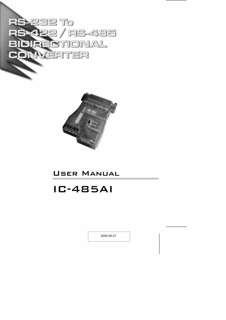
User Manual
IC-485AI
2002-09-27

Note: This equipment has been tested and found to comply withthe limits for a Class A digital device pursuant to Part 15 of theFCC Rules. These limits are designed to provide reasonableprotection against harmful interference when the equipment isoperated in a commercial environment. This equipmentgenerates, uses, and can radiate radio frequency energy and, ifnot installed and used in accordance with the instruction manual,may cause harmful interference to radio communications.Operation of this equipment in a residential area is likely to causeharmful interference, in which case the user will be required tocorrect the interference at his own expense.
2002-09-27
Packing ListThis package consists of:
1 IC-485AI Bidirectional Isolated Converter
1 Power Adapter
1 User Manual
Check to make sure that the unit was not damaged in shipping. If you encountera problem, contact your dealer.
Read this manual thoroughly and follow the installation and operationprocedures carefully to prevent any damage to the unit, and/or any of thedevices connected to it.
© Copyright 2001 ATEN® International Co., Ltd.Manual Part No. PAPE-0194-100
Printed in Taiwan 02/2002
All brand names and trademarks are the registered property of their respective owners.
2002-09-27
IC-485AI User Manual iii.

ContentsOverview . . . . . . . . . . . . . . . . . . . . . . . . . . . . . . . . . . . . . . . . . . . . . . . . . . . . . . 1Features. . . . . . . . . . . . . . . . . . . . . . . . . . . . . . . . . . . . . . . . . . . . . . . . . . . . . . . 2Components. . . . . . . . . . . . . . . . . . . . . . . . . . . . . . . . . . . . . . . . . . . . . . . . . . . . 3
Top View: . . . . . . . . . . . . . . . . . . . . . . . . . . . . . . . . . . . . . . . . . . . . . . . . . . . 3Bottom View: . . . . . . . . . . . . . . . . . . . . . . . . . . . . . . . . . . . . . . . . . . . . . . . . 4DIP Switch Configuration . . . . . . . . . . . . . . . . . . . . . . . . . . . . . . . . . . . . . . . 5
Operating Modes . . . . . . . . . . . . . . . . . . . . . . . . . . . . . . . . . . . . . . . . . . . . . . . . 7Point-to-Point . . . . . . . . . . . . . . . . . . . . . . . . . . . . . . . . . . . . . . . . . . . . . . . . 7Multidrop . . . . . . . . . . . . . . . . . . . . . . . . . . . . . . . . . . . . . . . . . . . . . . . . . . . 9Simplex . . . . . . . . . . . . . . . . . . . . . . . . . . . . . . . . . . . . . . . . . . . . . . . . . . . 11
Installation . . . . . . . . . . . . . . . . . . . . . . . . . . . . . . . . . . . . . . . . . . . . . . . . . . . . 12RS-422 / RS-485 Installation Diagrams. . . . . . . . . . . . . . . . . . . . . . . . . . . 13
Appendix . . . . . . . . . . . . . . . . . . . . . . . . . . . . . . . . . . . . . . . . . . . . . . . . . . . . . 14Terminal Block Pin Assignments . . . . . . . . . . . . . . . . . . . . . . . . . . . . . . . . 14Circuit Test . . . . . . . . . . . . . . . . . . . . . . . . . . . . . . . . . . . . . . . . . . . . . . . . . 14RS-485 Operation Mode Flow Charts . . . . . . . . . . . . . . . . . . . . . . . . . . . . 15DCE / DTE Connection Description. . . . . . . . . . . . . . . . . . . . . . . . . . . . . . 17Specifications . . . . . . . . . . . . . . . . . . . . . . . . . . . . . . . . . . . . . . . . . . . . . . . 18Troubleshooting . . . . . . . . . . . . . . . . . . . . . . . . . . . . . . . . . . . . . . . . . . . . . 19Limited Warranty . . . . . . . . . . . . . . . . . . . . . . . . . . . . . . . . . . . . . . . . . . . . 19
2002-09-27
iv. IC-485AI User Manual
OverviewAlthough RS-232 serial ports are found on almost every computer, because oftheir slow transmission speeds, limited range, and limited networkingcapabilities, they are not an effective solution for industrial strength longdistance communications systems.
Systems based on the RS-422 and RS-485 standards, on the other hand, arenot subject to the RS-232 limitations because they utilize different voltage linesfor the data and control signals.
The IC-485AI Isolated Converter is a bidirectional converter that transparentlyconverts RS-232 signals to RS-422 / RS-485 signals (and vice versa), thuspermitting the creation of reliable long distance data communications systemsusing standard computer hardware.
The IC-485AI provides Point-to-Point; Multidrop; and Simplex operations overdistances of up to 1200 m (4000 ft.). Designed with built in optocouplers forexceptional signal isolation, plus transformers for excellent power isolation, thisextremely reliable isolated converter enhances the quality of datacommunications at the same time that it protects your equipment from electricalsurges of up to 2000 volts.
2002-09-27
IC-485AI User Manual 1
Features
Automatic internal RS-485 bus supervision
No external flow control signals for RS-485 required
Transient suppression on RS-485 data lines
LEDs for easy status monitoring
Minimum 2000V isolation protection
Up to 115.2 Kbps data throughput
DCE / DTE selectable
Point-to-Point; Multidrop; and Simplex operating modes
Four wire full duplex; two wire half duplex
Cable distance of up to 1200 m (4000 ft.)
Compact size
2002-09-27
2 IC-485AI User Manual
Components
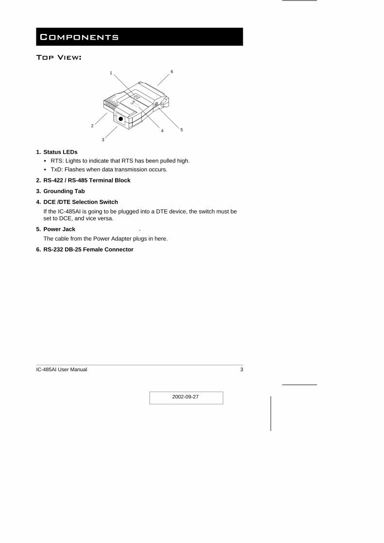
Top View:
1. Status LEDs
RTS: Lights to indicate that RTS has been pulled high.
TxD: Flashes when data transmission occurs.
2. RS-422 / RS-485 Terminal Block
3. Grounding Tab
4. DCE /DTE Selection Switch
If the IC-485AI is going to be plugged into a DTE device, the switch must beset to DCE, and vice versa.
5. Power Jack
The cable from the Power Adapter plugs in here.
6. RS-232 DB-25 Female Connector
2
3
4 5
61
2002-09-27
IC-485AI User Manual 3
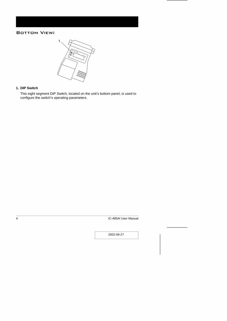
Bottom View:
1. DIP Switch
This eight segment DIP Switch, located on the unit’s bottom panel, is used toconfigure the switch’s operating parameters.
1
2002-09-27
4 IC-485AI User Manual

DIP Switch ConfigurationThe IC-485AI’s settings for Baud Rate, Data Format, and RS-422 / RS-485Mode are configured by setting the eight segment DIP Switch located on itsbottom panel.
Note: When you change any of the DIP Switch settings, you must reset thedevice by powering it off, then powering it on again.
SW 1-3: Baud Rate
Baud Rate SW1 SW2 SW3
1200 ON ON ON
2400 OFF ON ON
4800 ON OFF ON
9600 OFF OFF ON
19200 ON ON OFF
38400 OFF ON OFF
57600 ON OFF OFF
115200 OFF OFF OFF
Note: 1. The Baud Rate must be the same for all units on the installation.
2. The default is 9600 bps.
SW 4: Reserved
2002-09-27
IC-485AI User Manual 5
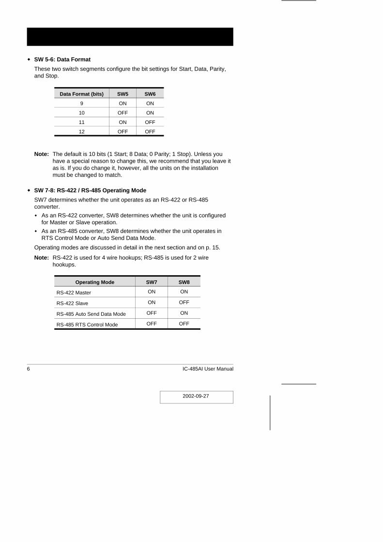
SW 5-6: Data Format
These two switch segments configure the bit settings for Start, Data, Parity,and Stop.
Data Format (bits) SW5 SW6
9 ON ON
10 OFF ON
11 ON OFF
12 OFF OFF
Note: The default is 10 bits (1 Start; 8 Data; 0 Parity; 1 Stop). Unless youhave a special reason to change this, we recommend that you leave itas is. If you do change it, however, all the units on the installationmust be changed to match.
SW 7-8: RS-422 / RS-485 Operating Mode
SW7 determines whether the unit operates as an RS-422 or RS-485converter.
As an RS-422 converter, SW8 determines whether the unit is configuredfor Master or Slave operation.
As an RS-485 converter, SW8 determines whether the unit operates inRTS Control Mode or Auto Send Data Mode.
Operating modes are discussed in detail in the next section and on p. 15.
Note: RS-422 is used for 4 wire hookups; RS-485 is used for 2 wirehookups.
Operating Mode SW7 SW8
RS-422 Master ON ON
RS-422 Slave ON OFF
RS-485 Auto Send Data Mode OFF ON
RS-485 RTS Control Mode OFF OFF
2002-09-27
6 IC-485AI User Manual
Operating ModesThe IC-485AI supports three operating modes: Point-to-Point; Multidrop; andSimplex. Point-to-Point and Multidrop can be configured for Full or Half Duplex.Each of the operating modes is explained below.
Point-to-PointA Point-to-Point configuration is one in which two devices, located at twodifferent places are linked for communication by a pair of IC-485AI units. Thereare two configurations: Point-to-Point Full Duplex, and Point-to-Point HalfDuplex.
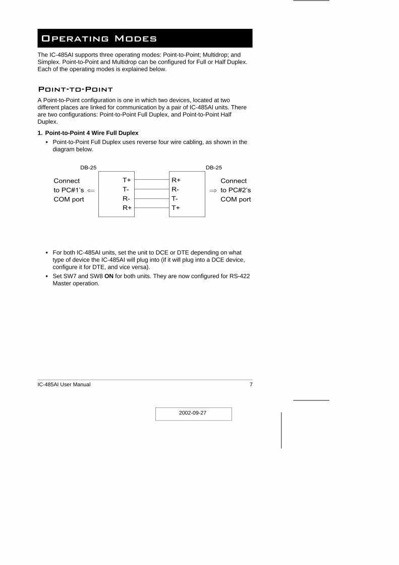
1. Point-to-Point 4 Wire Full Duplex
Point-to-Point Full Duplex uses reverse four wire cabling, as shown in thediagram below.
For both IC-485AI units, set the unit to DCE or DTE depending on whattype of device the IC-485AI will plug into (if it will plug into a DCE device,configure it for DTE, and vice versa).
Set SW7 and SW8 ON for both units. They are now configured for RS-422Master operation.
T+
T-
R-
R+
R+
R-
T-
T+
Connect
to PC#1’s
COM port
Connect
to PC#2’s
COM port
DB-25 DB-25
2002-09-27
IC-485AI User Manual 7

2. Point-to-Point 2 Wire Half Duplex
Point-to-Point Half Duplex uses straight through two wire cabling, asshown in the diagram below.
For both IC-485AI units, set the unit to DCE or DTE depending on whattype of device the IC-485AI will plug into (if it will plug into a DCE device,configure it for DTE, and vice versa).
Set SW7 OFF and SW8 ON for both units. They are now configured forRS-485 Auto Send Data Mode (see p. 15 for RS-485 operation details).
T+
T-
R-
R+
R+
R-
T-
T+
Connect
to PC#1’s
COM port
Connect
to PC#2’s
COM port
DB-25 DB-25
2002-09-27
8 IC-485AI User Manual
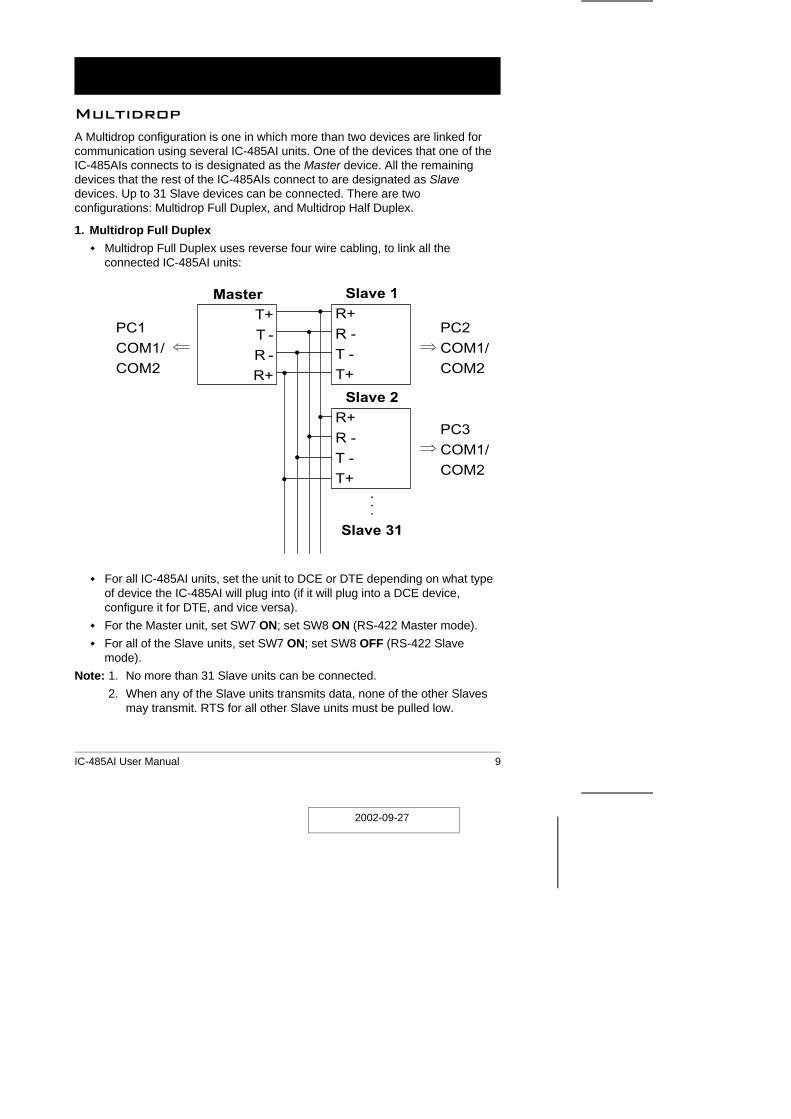
MultidropA Multidrop configuration is one in which more than two devices are linked forcommunication using several IC-485AI units. One of the devices that one of theIC-485AIs connects to is designated as the Master device. All the remainingdevices that the rest of the IC-485AIs connect to are designated as Slavedevices. Up to 31 Slave devices can be connected. There are twoconfigurations: Multidrop Full Duplex, and Multidrop Half Duplex.
1. Multidrop Full Duplex
Multidrop Full Duplex uses reverse four wire cabling, to link all theconnected IC-485AI units:
For all IC-485AI units, set the unit to DCE or DTE depending on what typeof device the IC-485AI will plug into (if it will plug into a DCE device,configure it for DTE, and vice versa).
For the Master unit, set SW7 ON; set SW8 ON (RS-422 Master mode).
For all of the Slave units, set SW7 ON; set SW8 OFF (RS-422 Slavemode).
Note: 1. No more than 31 Slave units can be connected.
2. When any of the Slave units transmits data, none of the other Slavesmay transmit. RTS for all other Slave units must be pulled low.
MasterT+
T -
R -
R+
Slave 1R+
R -
T -
T+
Slave 2R+
R -
T -
T+...
Slave 31
PC1
COM1/
COM2
PC2
COM1/
COM2
PC3
COM1/
COM2
2002-09-27
IC-485AI User Manual 9

2. Multidrop Half Duplex
Multidrop Half Duplex uses reverse two wire cabling, to link all the connectedIC-485AI units:
For all IC-485AI units, set the unit to DCE or DTE depending on what typeof device the IC-485AI will plug into (if it will plug into a DCE device,configure it for DTE, and vice versa).
For all of the units set SW7 and SW8 according to the table on p. 6 toconfigure each unit’s RS-485 operating mode (see p. 15 for RS-485operation details).
Note: No more than 31 Slave units can be connected.
MasterT+
T -
R -
R+
Slave 1R+
R -
T -
T+
Slave 2R+
R -
T -
T+
PC1
COM1/
COM2
PC2
COM1/
COM2
PC3
COM1/
COM2
Slave 3R+
R -
T -
T+..
Slave 31
PC4
COM1/
COM2
2002-09-27
10 IC-485AI User Manual

SimplexA Simplex configuration is one in which more than two devices are linked forcommunication using several IC-485AI units in a manner similar to Multidrop.The difference is that in a Simplex configuration, the Master device can onlytalk, and the Slave devices can only listen.
Simplex uses reverse two wire cabling to link all the connected IC-485AIunits, as shown in the figure below:
For all IC-485AI units, set the unit to DCE or DTE depending on what type ofdevice the IC-485AI will plug into (if it will plug into a DCE device, configure itfor DTE, and vice versa).
For all of the units (Master and Slave), set SW7 ON; set SW8 ON.
Note: No more than 31 Slave units can be connected.
MasterT+
T -
R -
R+
Slave 1
R+
R -
T -
T+
Slave 2
R+
R -
T -
T+
Slave 3
R+
R -
T -
T+
:
:
Slave 31
PC1
COM1/
COM2
PC2
COM1/
COM2
PC3
COM1/
COM2
PC4
COM1/
COM2
2002-09-27
IC-485AI User Manual 11
Installation
1. Make sure that all the devices you will be connecting up are powered off.
2. Set each IC-485AI’s configuration switches according to the informationprovided in the Switch Configuration and Operating Modes sections.
3. Plug the IC-485AI’s DB-25 female connector into the computer’s RS-232Cport.
4. Connect the IC-485AI units to each other.
1. Use two or four wire twisted pair cable in a reverse or straight throughconfiguration according to the information provided in the SwitchConfiguration and Operating Modes sections.
2. See p. 14 for the Terminal Block pin assignments.
5. Power on the computers. The units are now ready for operation.
Note: When connecting units over long distances, it may be necessary to install120 Ω resistors. See the diagrams on the next page for details.
2002-09-27
12 IC-485AI User Manual

RS-422 / RS-485 Installation Diagrams
Note: When the distance between both ends of the installation is large and/orthe transmitted signals are unstable, insert 120 Ω terminal resistorsbetween pins 1 and 2 and between pins 3 and 4 on the terminal blocks ofthe two units at each end of the installation.
Note: When the distance between both ends of the installation is large and/orthe transmitted signals aren’t stable, insert a 120 Ω terminal resistorbetween pins 1 and 2 on the terminal blocks of the two units at each endof the installation.
MasterT+
T -
R -
R+
Slave 31R+
R -
T -
T+
Slave 1 Slave 30
4,000’
RS-422 Full Duplex
MasterT+
T -
R -
R+
Slave 31R+
R -
T -
T+
Slave 1 Slave 30
4,000’RS-485 Half Duplex
2002-09-27
IC-485AI User Manual 13
Appendix
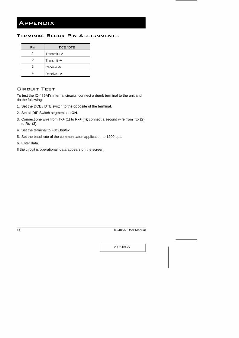
Terminal Block Pin Assignments
Pin DCE / DTE
1 Transmit +V
2 Transmit -V
3 Receive -V
4 Receive +V
Circuit TestTo test the IC-485AI’s internal circuits, connect a dumb terminal to the unit anddo the following:
1. Set the DCE / DTE switch to the opposite of the terminal.
2. Set all DIP Switch segments to ON.
3. Connect one wire from Tx+ (1) to Rx+ (4); connect a second wire from Tx- (2)to Rx- (3).
4. Set the terminal to Full Duplex.
5. Set the baud rate of the communicaton application to 1200 bps.
6. Enter data.
If the circuit is operational, data appears on the screen.
2002-09-27
14 IC-485AI User Manual

RS-485 Operation Mode Flow Charts
RTS Control Mode
The IC-485AI operates in RS-485 RTS Control Mode when both SW7 andSW8 are set to OFF.
In this mode, RTS is pulled high when the computer makes a request tosend data.
2002-09-27
IC-485AI User Manual 15
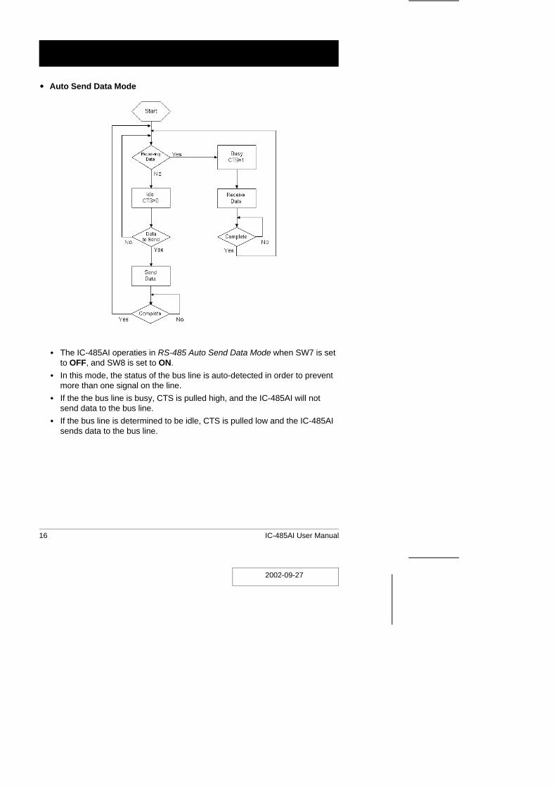
Auto Send Data Mode
The IC-485AI operaties in RS-485 Auto Send Data Mode when SW7 is setto OFF, and SW8 is set to ON.
In this mode, the status of the bus line is auto-detected in order to preventmore than one signal on the line.
If the the bus line is busy, CTS is pulled high, and the IC-485AI will notsend data to the bus line.
If the bus line is determined to be idle, CTS is pulled low and the IC-485AIsends data to the bus line.
2002-09-27
16 IC-485AI User Manual
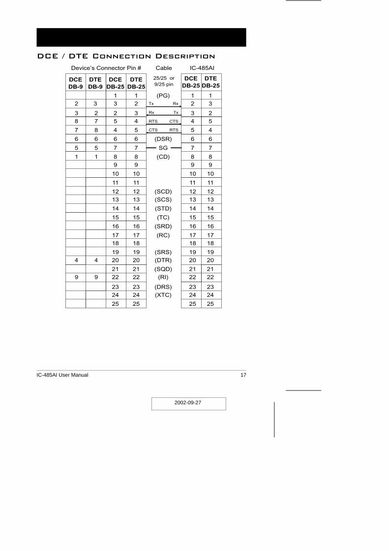
DCE / DTE Connection Description
DCE DTE DCE DTEDB-9 DB-9 DB-25 DB-25
1 1 (PG) 1 12 3 3 2 2 3
3 2 2 3 3 28 7 5 4 4 5
7 8 4 5 5 4
6 6 6 6 (DSR) 6 6
5 5 7 7 SG 7 7
1 1 8 8 (CD) 8 89 9 9 9
10 10 10 10
11 11 11 11
12 12 (SCD) 12 1213 13 (SCS) 13 13
14 14 (STD) 14 14
15 15 (TC) 15 15
16 16 (SRD) 16 16
17 17 (RC) 17 1718 18 18 18
19 19 (SRS) 19 194 4 20 20 (DTR) 20 20
21 21 (SQD) 21 219 9 22 22 (RI) 22 22
23 23 (DRS) 23 2324 24 (XTC) 24 24
25 25 25 25
Tx Rx
Rx Tx
RTS CTS
CTS RTS
Cable
25/25 or9/25 pin
IC-485AIDevice’s Connector Pin #
DCE DTEDB-25 DB-25
2002-09-27
IC-485AI User Manual 17

Specifications
Function Specification
Power Consumption DC 9V; 900mW (max.)
Data Rate Up to 115.2 Kbps under 1200 m (4000 ft.)
Connectors 1 x DB-25 female (RS-232);1 x 4 Post Terminal Block (RS-422 / RS-485);1 x Grounding Tab
FunctionSwitches
Slide Switch DCE / DTE Select
DIP Switch Segment 1-3: Baud Rate;Segment 4: Reserved;Segment 5&6: Data Format (bits);Segment 7&8: RS-422 / RS-485 Select
Cable Distance Up to 1200 m (4000 ft.)
Operating Temperature 0 ~ 50o C
Storage Temperature -20 ~ 60o C
Humidity 0 ~ 80% RH
Housing Plastic (ABS)
Weight 60 g
Dimensions (L x W x H) 54 x 74.5 x 18.5 mm
2002-09-27
18 IC-485AI User Manual
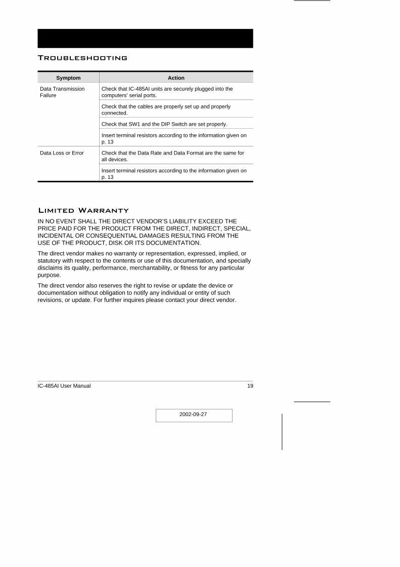
Troubleshooting
Symptom Action
Data TransmissionFailure
Check that IC-485AI units are securely plugged into thecomputers’ serial ports.
Check that the cables are properly set up and properlyconnected.
Check that SW1 and the DIP Switch are set properly.
Insert terminal resistors according to the information given onp. 13
Data Loss or Error Check that the Data Rate and Data Format are the same forall devices.
Insert terminal resistors according to the information given onp. 13
Limited WarrantyIN NO EVENT SHALL THE DIRECT VENDOR’S LIABILITY EXCEED THEPRICE PAID FOR THE PRODUCT FROM THE DIRECT, INDIRECT, SPECIAL,INCIDENTAL OR CONSEQUENTIAL DAMAGES RESULTING FROM THEUSE OF THE PRODUCT, DISK OR ITS DOCUMENTATION.
The direct vendor makes no warranty or representation, expressed, implied, orstatutory with respect to the contents or use of this documentation, and speciallydisclaims its quality, performance, merchantability, or fitness for any particularpurpose.
The direct vendor also reserves the right to revise or update the device ordocumentation without obligation to notify any individual or entity of suchrevisions, or update. For further inquires please contact your direct vendor.
2002-09-27
IC-485AI User Manual 19