user manual - mega systems inc · user manual table of contents ... el-bum1 linx 1 unit bumper-bum2...
TRANSCRIPT
USER MANUAL
Table of Contents Safety Information……………………………………………………………………………………………. 2
Specifications…………………………………………………………………………………………………….. 3 Product Overview……………………………………………………………………………………………… 4
Power & Signal Connection………………………………………………………………………...... 6
Installation......................................................................................................................... 7 Rigging the Fixture………………………………………………………………………………………….12
Service.................................................................................................................................12 Maintenance…………………………………………………………………………………………………….13
Parts List............................................................................................................................ 13
Software……………………………………………………………………………………………………………14


Check that the unit has not been damaged during transport
Protection against fire
Protection against electrical hazards
1. Maintain a minimum of 2 foot distance from any type of flame.
2. Replace fuse only with the specified type and rating. 3. Do not install the unit to close to a heat source.
4. Make sure cable are properly secured. 5. Protect the power and data cords from being walked on or pinched
1. Disconnect power before servicing.
2. For Connection to power supply proceed to page 7 3. This unit must be earthed (electronically)
4. Do not expose to rain or moisture. 5. Do not extend power supply cable.
Protection against mechanical hazards
1. Use safety chain when hanging unit.
2. Make sure all clips are securely clipped together.
2

Specifications
Fixture Flight Case
EL-37-Linx 37.5 Panel EL-37case12
Mechanical Specifications
Pixel Pitch: 37.5mm Section Resolution: 8x32, 256 pixel per Links Brightness: 2300CD-m2 Viewing Angel: 120° Vertical 120° Horizontal IP Rating: IP 63 Transparency: 57% Connection: ODU 5 pin signal connection, ODU 2 pin power connection
Electrical Specifications
LED Type: SMD tri color Led Quantity: 256 LED Lifetime: 100,000 hours estimated Power input Manually Switchable 110V or 220V Power output DC 24V Power Consumption: 75 Watts
47
.25
” /
12
00
mm
In:47.25” x 11.81” x 1” / mm: 1200 x 300 x 25
Weight: 5.8lbs
Weight / Dimensions
3
11.81” / 300mm
DATA OUT A DVI INPUT 100-240V 50/60
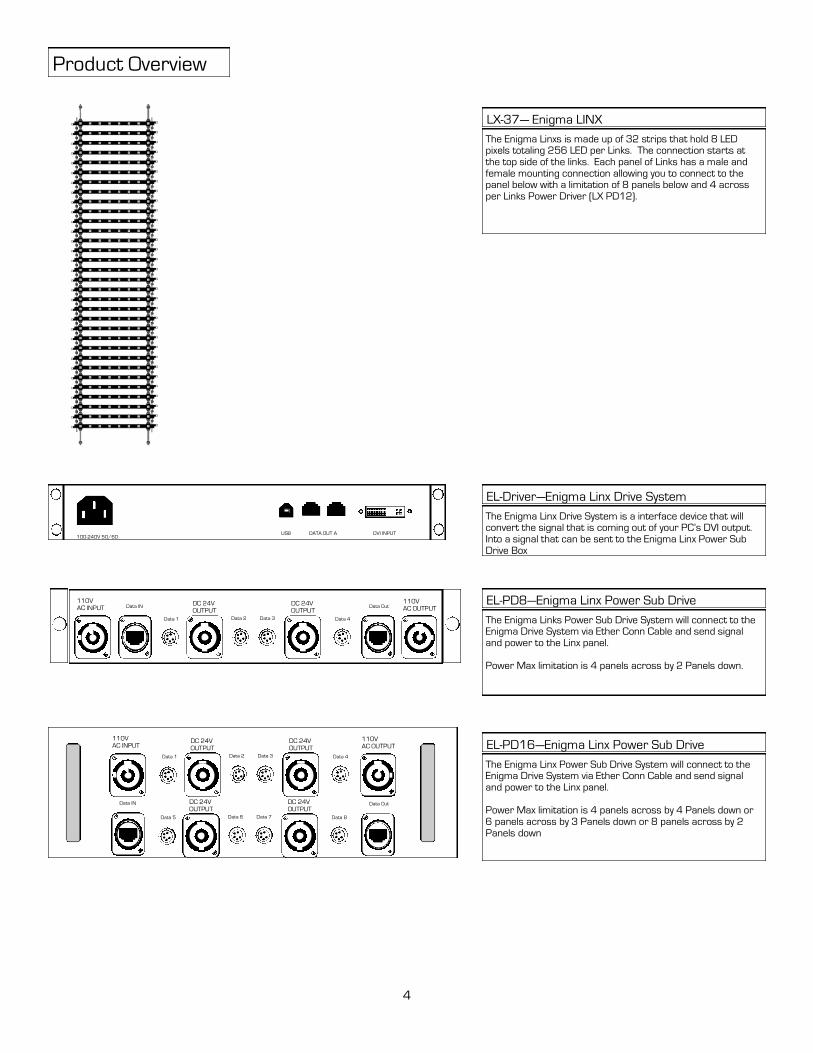
Product Overview
Data IN 110V AC OUTPUT
DC 24V OUTPUT
The Enigma Linxs is made up of 32 strips that hold 8 LED pixels totaling 256 LED per Links. The connection starts at the top side of the links. Each panel of Links has a male and female mounting connection allowing you to connect to the panel below with a limitation of 8 panels below and 4 across per Links Power Driver (LX PD12).
LX-37— Enigma LINX
The Enigma Linx Drive System is a interface device that will convert the signal that is coming out of your PC’s DVI output. Into a signal that can be sent to the Enigma Linx Power Sub Drive Box
EL-Driver—Enigma Linx Drive System
The Enigma Links Power Sub Drive System will connect to the Enigma Drive System via Ether Conn Cable and send signal and power to the Linx panel. Power Max limitation is 4 panels across by 2 Panels down.
EL-PD8—Enigma Linx Power Sub Drive
4
110V AC INPUT Data Out
Data 1
DC 24V OUTPUT
Data 2 Data 3 Data 4
USB
The Enigma Linx Power Sub Drive System will connect to the Enigma Drive System via Ether Conn Cable and send signal and power to the Linx panel. Power Max limitation is 4 panels across by 4 Panels down or 6 panels across by 3 Panels down or 8 panels across by 2 Panels down
EL-PD16—Enigma Linx Power Sub Drive
Data IN
110V AC OUTPUT
DC 24V OUTPUT
110V AC INPUT
Data Out
Data 1
DC 24V OUTPUT
Data 2 Data 3 Data 4
DC 24V OUTPUT
Data 5
DC 24V OUTPUT
Data 6 Data 7 Data 8
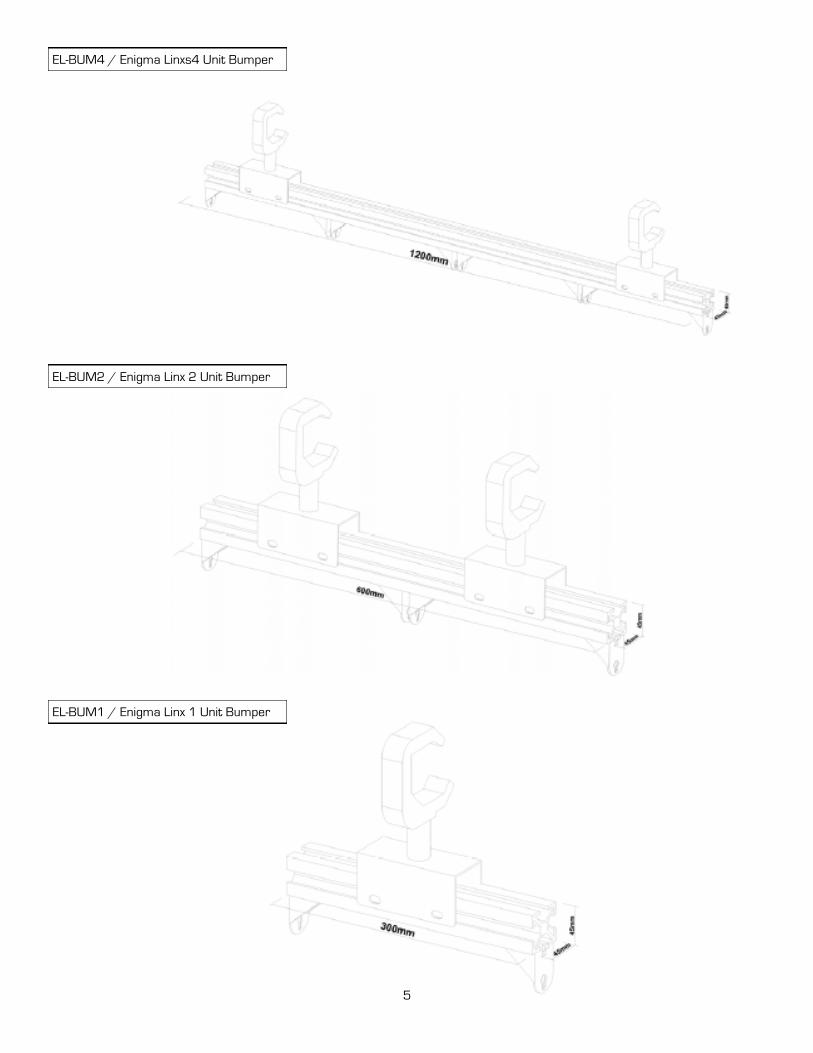
EL-BUM4 / Enigma Linxs4 Unit Bumper
EL-BUM2 / Enigma Linx 2 Unit Bumper
EL-BUM1 / Enigma Linx 1 Unit Bumper
5
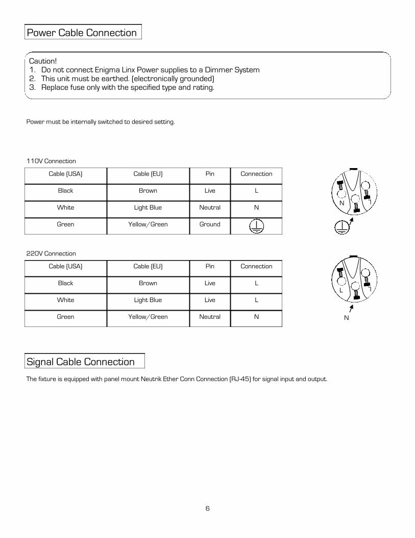
Power Cable Connection
Caution! 1. Do not connect Enigma Linx Power supplies to a Dimmer System 2. This unit must be earthed. (electronically grounded) 3. Replace fuse only with the specified type and rating.
Cable (USA) Cable (EU) Pin Connection
Black Brown
White
Green
Light Blue
Yellow/Green
Live
Neutral
Ground
L
N
110V Connection
N
L
Signal Cable Connection
The fixture is equipped with panel mount Neutrik Ether Conn Connection (RJ-45) for signal input and output.
Cable (USA) Cable (EU) Pin Connection
Black Brown
White
Green
Light Blue
Yellow/Green
Live
Live
Neutral
L
L
220V Connection
N
L
L
N
6
Power must be internally switched to desired setting.
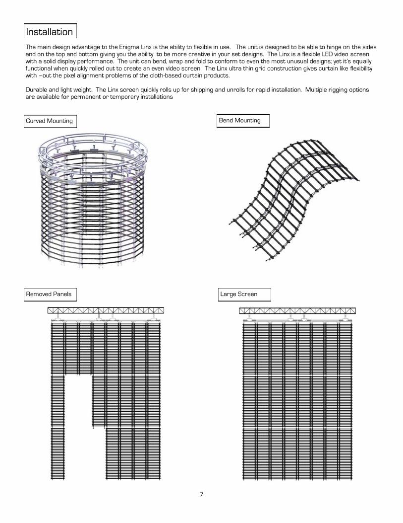
Installation
The main design advantage to the Enigma Linx is the ability to flexible in use. The unit is designed to be able to hinge on the sides
and on the top and bottom giving you the ability to be more creative in your set designs. The Linx is a flexible LED video screen with a solid display performance. The unit can bend, wrap and fold to conform to even the most unusual designs; yet it’s equally
functional when quickly rolled out to create an even video screen. The Linx ultra thin grid construction gives curtain like flexibility with –out the pixel alignment problems of the cloth-based curtain products.
Durable and light weight, The Linx screen quickly rolls up for shipping and unrolls for rapid installation. Multiple rigging options are available for permanent or temporary installations
Curved Mounting Bend Mounting
Removed Panels Large Screen
7
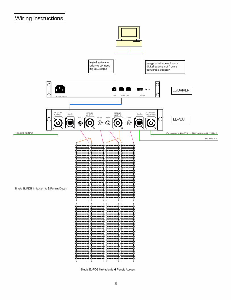
Install software prior to connect-ing USB cable
EL-DRIVER
8
Wiring Instructions
DATA OUT A DVI INPUT 100-240V 50/60
USB
Data IN 110/220 AC OUTPUT
DC 24V OUTPUT
110/220 AC INPUT Data Out
Data 1
DC 24V OUTPUT
Data 2 Data 3 Data 4
EL-PD8
Image must come from a digital source not from a converted adapter
110/220 AC INPUT 110V maximum of 3 LX-PD12 / 220V maximum of 6 LX-PD12
DATA OUTPUT
Single EL-PD8 limitation is 4 Panels Across
Single EL-PD8 limitation is 2 Panels Down
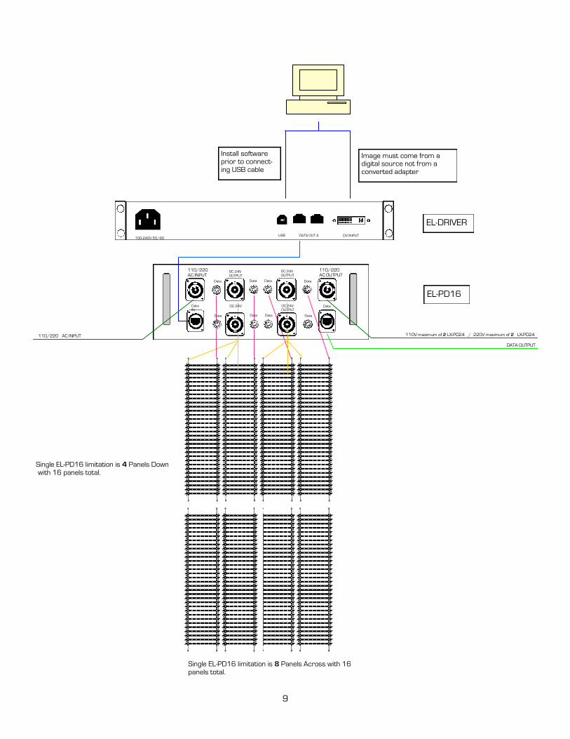
Install software prior to connect-ing USB cable
EL-DRIVER
9
DATA OUT A DVI INPUT 100-240V 50/60
USB
EL-PD16
Image must come from a digital source not from a converted adapter
110/220 AC INPUT
DATA OUTPUT
Single EL-PD16 limitation is 8 Panels Across with 16 panels total.
Single EL-PD16 limitation is 4 Panels Down with 16 panels total.
Data
IN
110/220 AC OUTPUT
DC 24V
OUTPUT
110/220 AC INPUT
Data
Data
DC 24V
OUTPUT
Data Data Data
110V maximum of 2 LX-PD24 / 220V maximum of 2 LX-PD24
DC 24V
Data
DC 24V
OUTPUT
Data Data Data

Install software prior to connect-ing USB cable
EL-DRIVER
DATA OUT A DVI INPUT 100-240V 50/60
USB
Image must come from a digital source not from a converted adapter
Multiple Unit Installation
D 1D1 DD
DD D D
D 1D1 DD
DD D D
D 1D1 DD
DD D D
D 1D1 DD
DD D D
D 1D1 DD
DD D D
D 1D1 DD
DD D D
D 1D1 DD
DD D D
D 1D1 DD
DD D D
2 Down Total
10
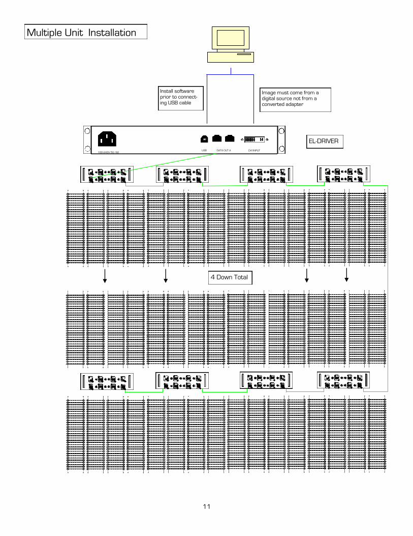
Install software prior to connect-ing USB cable
EL-DRIVER
DATA OUT A DVI INPUT 100-240V 50/60
USB
Image must come from a digital source not from a converted adapter
Multiple Unit Installation
4 Down Total
11
1D1
D
DD
D D D
DD
DD D D
1D1
D
DD
D D D
DD
DD D D
1D1
D
DD
D D D
DD
DD D D
1D1
D
DD
D D D
DD
DD D D
1D1
D
DD
D D D
DD
DD D D
1D1
D
DD
D D D
DD
DD D D
1D1
D
DD
D D D
DD
DD D D
1D1
D
DD
D D D
DD
DD D D
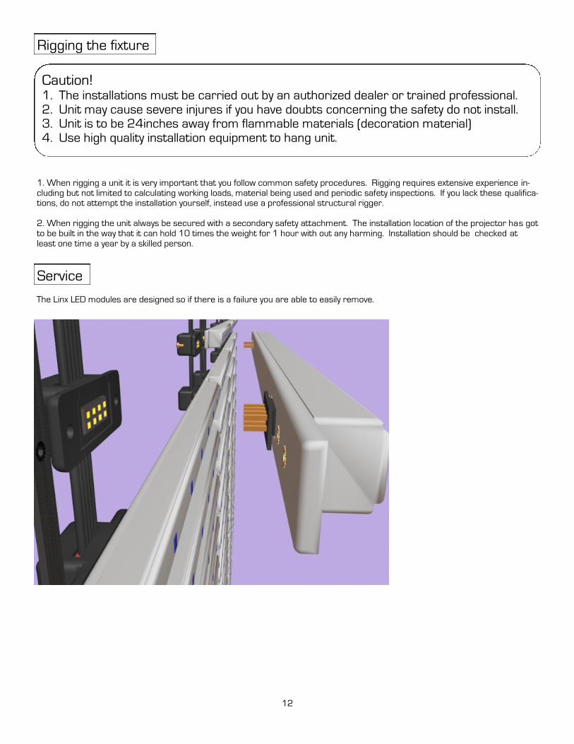
Caution! 1. The installations must be carried out by an authorized dealer or trained professional. 2. Unit may cause severe injures if you have doubts concerning the safety do not install. 3. Unit is to be 24inches away from flammable materials (decoration material) 4. Use high quality installation equipment to hang unit.
1. When rigging a unit it is very important that you follow common safety procedures. Rigging requires extensive experience in-
cluding but not limited to calculating working loads, material being used and periodic safety inspections. If you lack these qualifica-tions, do not attempt the installation yourself, instead use a professional structural rigger.
2. When rigging the unit always be secured with a secondary safety attachment. The installation location of the projector has got
to be built in the way that it can hold 10 times the weight for 1 hour with out any harming. Installation should be checked at
least one time a year by a skilled person.
Service
Rigging the fixture
The Linx LED modules are designed so if there is a failure you are able to easily remove.
12

Installation Maintenance: The operator has to make sure that the unit is operating safely and has the installations and electron-ics checked by an expert every 2 years.
The following points have to be considered during the inspection:
1) All screws used for installing the device or part of the device have to be tightly connected and must not be corroded.
2) There must not be any deformations on the housing, fixation and installation spots (ceiling, suspension, trussing). 3) The electronic power supply cables must not show any damages, material fatigue (e.g. porous cables) or sediments. Further
instructions depending on the installation spot and usage have to be adhered by a skilled installer and any safety problems have to be removed.
4) Make sure the fans are not blocked from air flow.
5) Make sure signal cables and LX-driver and LX-PD12 are not placed near any magnetic interference.
Disconnect from mains before starting maintenance operation!
Caution Danger to life!
We recommend a frequent cleaning of the device. Please use a moist, lint free cloth. Never use alcohol or solvents!
1) The objective lens will require periodic cleaning on usage and environment. Environment with foggers will require more peri-odic cleaning as fog fluid tends to build up residues, reducing the light output.
2) The cooling-fans should be cleaned monthly. DO NOT blow high pressure air into fans as incorrect rotation can damage the fans operation.
Note: There is no serviceable parts inside the device except for the lamp and the fuse. Maintenance and service operations are to be carried out by authorized dealers.
Replacing the power cable: If the power cable of this device becomes damaged, it has to be replaced by authorized dealers only In order to avoid hazards.
Should you have further questions , please contact your dealer.
Parts List
EL-PD8 Linx Power Supply & Driver 8
EL-PD16 Linx Power Supply & Driver 16
EL-DR Driver Card
EL-RC Receiving Card
EL-DRIVER Linx Driver
EN-C-DA-3 3 Foot Data Cable ODU Connection
EN-C-DA-13 13 Foot Data Cable ODU Connection
EN-C-PW-5 5 Foot Power Cable Neutrik to ODU
EN-CPW-13 13 Foot Power Cable Neutrik to ODU
EL-DRPS Linx Driver Power Supply
EL-BUM1 Linx 1 Unit Bumper
EL-BUM2 Linx 2 Unit Bumper
EL-BUM4 Linx 4 Unit Bumper
EL-PS Power Supply
EL-MOD Links Replacement LED module
Maintenance
13
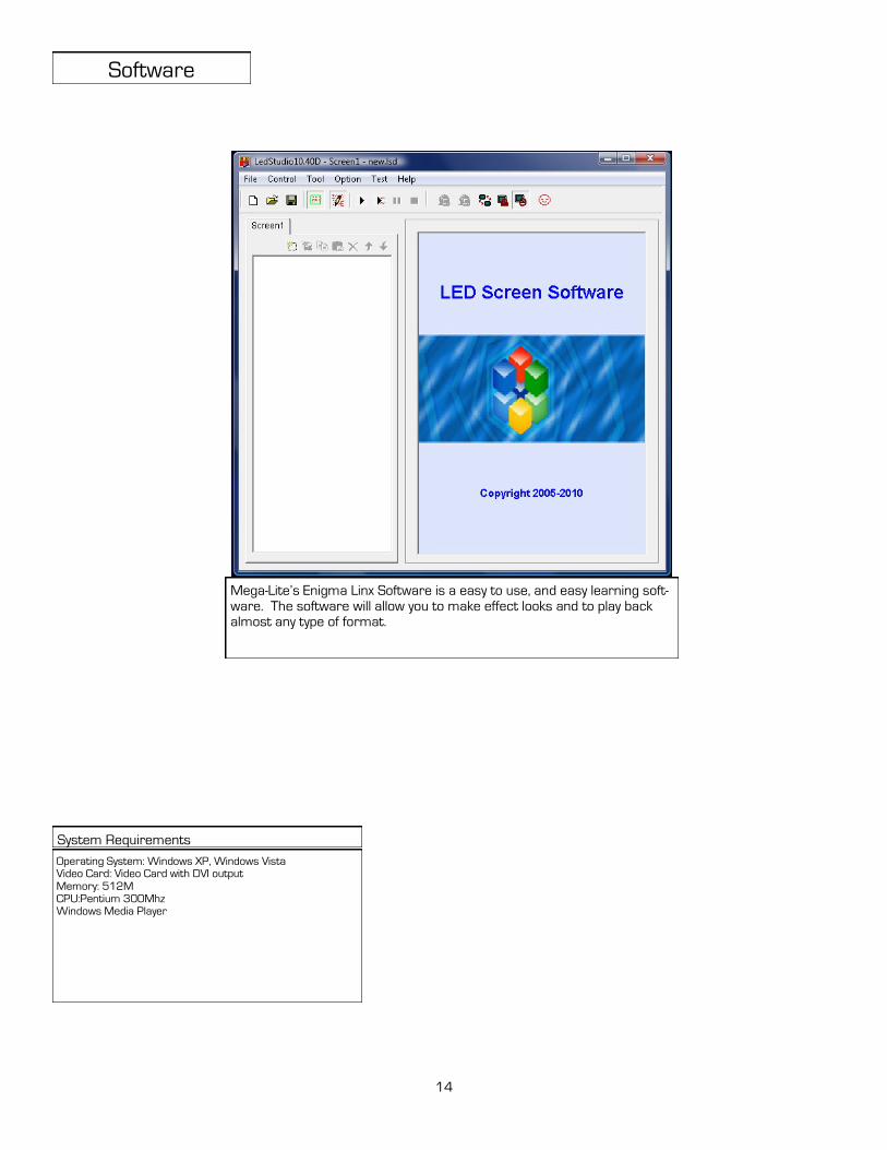
Software
Operating System: Windows XP, Windows Vista Video Card: Video Card with DVI output Memory: 512M CPU:Pentium 300Mhz Windows Media Player
System Requirements
14
Mega-Lite’s Enigma Linx Software is a easy to use, and easy learning soft-
ware. The software will allow you to make effect looks and to play back almost any type of format.
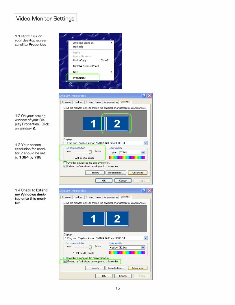
Video Monitor Settings
1.1 Right click on
your desktop screen
scroll to Properties
1.2 On your setting
window of your Dis-play Properties. Click
on window 2.
1.3 Your screen resolution for moni-
tor 2 should be set
to 1024 by 768
15
1.4 Check to Extend
my Windows desk-
top onto this moni-
tor

Mega-Lite 5718 Kenwick St
San Antonio, TX 78238 Ph 210-684-2600 Fax 210-855-6279
www.mega-lite.com / [email protected]