user manual - pellet stoves, fireplaces, pellet ...eng.ravelligroup.it/userfiles/files/pdf...
TRANSCRIPT

USER MANUAL HYDRO TOUCH
Stove model:
Stove serial number:
Date of installation:
Support reference data:
Telephone number:

User manual HYDRO TOUCH Page3
Vers. 01 of:18.03.14
CONTENTS
Introduction..........................................................................................................................................................
Safety information................................................................................................................................................
General information.............................................................................................................................................What are wooden pellets?.......................................................................................................................................................................How is a stove made?.............................................................................................................................................................................Combustion.............................................................................................................................................................................................Safety devices.........................................................................................................................................................................................Technical standards and Directives.........................................................................................................................................................
Stove installation.................................................................................................................................................Advice for installation...............................................................................................................................................................................Approved installations.............................................................................................................................................................................System compatibility check.....................................................................................................................................................................Air vent....................................................................................................................................................................................................Fume duct and fittings.............................................................................................................................................................................Flue..........................................................................................................................................................................................................Flue dataplate..........................................................................................................................................................................................Chimney terminal (UNI 7129/08).............................................................................................................................................................Testing and commissioning.....................................................................................................................................................................Additional documentation and informations for the user.........................................................................................................................Maintenance frequency...........................................................................................................................................................................Examples of installation of a pellet stove/thermo-stove/ boiler................................................................................................................Examples of installation of a pellet stove/thermostove/ insert..................................................................................................................
Hydraulic installation...........................................................................................................................................Safety devices for open tank system.......................................................................................................................................................Safety devices for closed tank system....................................................................................................................................................Installation advice....................................................................................................................................................................................Examples of hydraulic installation...........................................................................................................................................................Direct circuit to the system......................................................................................................................................................................Direct circuit to the system in the presence of gas stove........................................................................................................................Direct connection to the system + DHW boiler in the presence of gas stove.........................................................................................Connection to a storage tank (puffer Pipe in Tank) in the presence of gas stove (1)..............................................................................Connection to a storage tank (puffer Pipe in Tank) in the presence of gas stove (2)..............................................................................Connection to a storage tank (puffer Pipe in Tank) in the presence of gas stove (3)..............................................................................Connection to a storage tank (puffer) + DHW boiler in the presence of gas stove (1)............................................................................Connection to a storage tank (puffer) + DHW boiler in the presence of gas stove (2)............................................................................
Preliminary operations.........................................................................................................................................Wiring......................................................................................................................................................................................................What to check befor turning on the stove................................................................................................................................................How to load the pellets............................................................................................................................................................................Description of control panel.....................................................................................................................................................................
Turning the device on..........................................................................................................................................Sequence of ignition phases...................................................................................................................................................................
Operating phases of the appliance......................................................................................................................Modulation...............................................................................................................................................................................................Comfort climate.......................................................................................................................................................................................Stand-by..................................................................................................................................................................................................
Description of functions.......................................................................................................................................STOVE STATUS icon..............................................................................................................................................................................USER MENU icon...................................................................................................................................................................................All menu icons.........................................................................................................................................................................................
Other functions available in USER MENU...........................................................................................................Chronothermostat....................................................................................................................................................................................External thermostat YES/NO activation...................................................................................................................................................Correction of pellet/air mixture.................................................................................................................................................................Summer/Winter setting............................................................................................................................................................................Language selection.................................................................................................................................................................................Work hours and warnings display/reset...................................................................................................................................................Displaying the factory settings.................................................................................................................................................................Display settings.......................................................................................................................................................................................Information on set system layout and support service............................................................................................................................Access to installer's settings....................................................................................................................................................................
Page 5
Page 6
Page 7Page 7Page 7Page 8Page 8Page 8
Page 9Page 9Page 9Page 9Page 9Page 10Page 10Page 10Page 11Page 12Page 12Page 13Page 15Page 18
Page 19 Page 19Page 19Page 19Page 20Page 20Page 21Page 22Page 23Page 24Page 25Page 26Page 27
Page 28Page 28Page 28Page 28Page 28
Page 32Page 32
Page 32Page 32Page 32Page 33
Page 33Page 33Page 34Page 34
Page 35Page 35Page 36Page 37Page 38Page 38Page 39Page 39Page 39Page 40Page 40

User manual HYDRO TOUCH Page4
Vers. 01 of:18.03.14
Contents
Pages displayed upon the activation of advanced layouts................................................................................Layout 1 (DHW boiler management + heating with external thermostat.................................................................................................Layout 2 (storage puffer management)..................................................................................................................................................Layout 3 (DHW boiler + storage puffer management)............................................................................................................................
Phase synthetical layout + colours available for switch on keys.....................................................................
Warning Pop-Up...................................................................................................................................................
Alarms.................................................................................................................................................................General table of possible alarms...........................................................................................................................................................
Anomalies............................................................................................................................................................General alarm table...............................................................................................................................................................................
Cleaning should be provided by the user...........................................................................................................Cleaning the surfaces.............................................................................................................................................................................Grate cleaning should be carried out before each switch on.................................................................................................................Cleaning the ash pan.............................................................................................................................................................................Cleaning glass........................................................................................................................................................................................Manual activation of turbolators and tube bundle cleaning....................................................................................................................
Accessories.........................................................................................................................................................Wall-mounted thermostat.......................................................................................................................................................................Electronic expansion board:...................................................................................................................................................................puffer......................................................................................................................................................................................................boiler.......................................................................................................................................................................................................Three-way valve.....................................................................................................................................................................................Mixing valve............................................................................................................................................................................................Anti-condensation valve.........................................................................................................................................................................NTC immersion probe for storage tanks................................................................................................................................................PT1000 probe for solar collector............................................................................................................................................................Solar collector.........................................................................................................................................................................................Solar unit................................................................................................................................................................................................Potential divider unit...............................................................................................................................................................................Additional pellet tank..............................................................................................................................................................................Domestic hot water kit (DHW)................................................................................................................................................................
Mother board wiring diagram.............................................................................................................................
Primary expansion wiring diagram.....................................................................................................................
Warranty..............................................................................................................................................................Warranty Certificate................................................................................................................................................................................Warranty conditions................................................................................................................................................................................
Info and Troubleshooting....................................................................................................................................
Contents
Page 41Page 41Page 42Page 43
Page 44
Page 44
Page 45Page 46
Page 47Page 47
Page 48Page 48Page 48Page 48Page 49Page 49
Page 50 Page 50Page 50Page 50Page 50Page 50Page 50Page 50Page 51Page 51Page 51Page 51Page 51Page 51Page 51
Page 52
Page 53
Page 54Page 54Page 54
Page 54
User manual HYDRO TOUCH Page5
Vers. 01 of:18.03.14
IntroductionWarning:We recommend you carefully read this booklet, which describes all the necessary phases for perfect functioning of your stove.
Note:The standards relevant to the installation and functioning contained in this manual can differ based on local standards in force. In this case, always comply with the indications of the local competent authorities. The drawings in this manual are indicative, not to scale.
Information:The packaging we have used offers good protection against any damage due to transport. In any case, check the stove immediately after delivery; in the event of possible visual damage, immediately inform your Ravelli srl dealer.
Description of the User and Maintenance Manual:With this User and Maintenance Manual, the company Ravelli srl wishes to provide the user with all the information on safe use of the stove, to avoid damage to people or property or parts of the stove.
Please carefully read this manual before use and any intervention on the product.
Warnings:Ravelli srl stoves are manufactured while paying particular attention to each component, to protect both the user and the installer from the danger of possible accidents. We recommend authorised staff pay particular attention to electrical connections after each intervention on the product.
Installation must be carried out by authorised staff, who must issue the customer with a declaration of conformity for the system, while taking full responsibility for final installation and the resulting good functioning of the product installed. It is necessary to keep in consideration all national, regional, provincial and municipal laws and standards for the country in which the equipment is installed. There is no liability on the part of AICO S.p.A. in the event of non-compliance with these precautions.
This user's manual forms an integral part of the product: ensure that it is always with the stove, also in the case of transfer to another owner or use or transfer to another location. In the event it is damaged or lost, ask technical support for a copy.
This stove is intended exclusively for the use for which it was specifically manufactured. Do not use the equipment as an incinerator or in any other way other than for what it was intended. The manufacturer is excluded from any contractual or out of contract responsibility for damage caused to people, animals or property, errors during installation, regulation and maintenance and improper use. No other fuel other than pellets can be used. Do not use combustible liquids.Having removed the packaging, ensure the integrity and completeness of the content.
All the electrical components forming the stove should be replaced exclusively by an authorised technical support centre using original pieces. Stove maintenance must be carried out at least once a year and scheduled in advance with the technical support service. Do not carry out any unauthorised changes to the equipment.
For safety purposes, remember:- This appliance is not intended for use by persons (including children) with reduced physical, sensory or mental capabilities, or lack
of experience and knowledge, unless they have been given supervision or instruction concerning use of the appliance by a personresponsible for their safety. The children should be supervised to make sure they do not play with the device.
- contact with the stove is not recommended if you are in your bare feet or with parts of your body wet;- it is forbidden to change the safety or regulation devices without the authorisation or without the instruction of Ravelli srl.- it is prohibited appliance installation in small rooms, bedrooms, rooms with explosive atmospheres etc..- we do not recommend loading pellets directly into the brazier before switching on the stove;- before connecting the appliance make sure the water mains pressure is below 3 bars;- the appliance works exclusively on wooden pellets; do not use the stove with other type of fuel.
The technician carrying out the installation must inform the user that:1. In the event of water leakage, close the water supply and promptly inform the technical support service.2. The operating pressure of the system must be periodically checked. Should the stove be inactive for prolonged periods:
we recommend you contact the technical support service to carry out the following operations:- turn off taps on the heating and sanitary systems;- empty the heating and sanitary system if there is a risk of freezing.
When the stove is functioning, it can reach very hot to touch temperatures, especially on the external surfaces: operate with care to avoid burns.
The stove was designed to function in any climatic condition; in the event of particularly adverse conditions (wind, frost) the safety systems could intervene and switch off the stove.If this occurs, urgently contact the technical support service and, in any case, doe not disable the safety systems.
User manual HYDRO TOUCH Page6
Vers. 01 of:18.03.14
Safety information
The stove must be installed and inspected by specialied staff trained by head office. Please carefully read this user and maintenance manual before installing and operating the stove. If you require further clarification, contact your nearest Ravelli srl dealer.The stove must be located indoors, never outdoors. Because it is controlied by an electronic board, it enables completely automatic and uncontrolled combustion: in fact, the control panel regulates activation, the 5 power levels and switch off phase, guaranteeing safe functioning. Most of the hot ash falls into a pan via the basket used for pellet combustion. Check, on a daily basis, if the basket is clean, because not all pellets are of the highest quality and they can leave residues which are difficult to remove. The glass is equipped with a special air wash for self-cleaning: yet, it is impossible to avoid a slight yellowish film on the glass after some hours of functioning.As previously mentioned, the stove should be fueled by 6 mm diameter pellets, but can also function with pellets with a different diameter: in this case, contact your Ravelli dealer for technical advice
NOTE
Prepare the installation location of the stove according to local, national and European regulations.•The stove must only be fueled with high quality pellets with a diameter of 6 mm as described in the dedicated chapter.•The stove cannot burn traditional wood.It is forbidden to use the stove as an incinerator. DANGER OF FIRE!!!Installation, electrical connection, verification of functioning and maintenance must be carried out by qualified and authorised•staff.Improper installation or poor maintenance (non-conformity with what is reported in the following booklet) may cause damage•to people or property. In this condition, RAVELLI SRL is released from all civil or criminal liability.Before connecting the stove to electrical power, the connection of the discharge tubes (specifically for pellet stoves, not in aluminium)•with the flue must be complete.The protection grid placed inside the pellet tank must never be removed.•There must be a sufficient exchange of air in the room in which the stove is installed.•Never open the door of the stove when functioning. • DANGER OF FIRE!!!It is forbidden to operate the stove with the door open or with the glass broken. DANGER OF FIRE!!!•When the stove is working, the surfaces, the glass, the handle and the tubes are very hot: during functioning these parts can only be•touched using adequate protective equipment.Do not switch on the stove without firstly carrying out a daily inspection as described in the MAINTENANCE chapter of this•manual.Do not dry washing on the stove. Any washing lines or similar must be kept an appropriate distance from the stove. DANGER•OF FIRE!!!Scrupulously follow the maintenance schedule.•Do not switch off the stove by disconnecting the electrical mains.•Do not clean the stove until the structure and ash are completely cold.•Carry out all operations in a completely safe and calm manner.•
ResponsibilitiesWith the delivery of this manual, Ravelli srl declines all civil and criminal liability for accidents deriving from the partial or total non-compliance with instructions contained in it.Ravelli srl declines ali liability deriving from improper use of the stove, from incorrect use by the user, from unauthorised changes and/or repairs and from use of non-original spare parts. The manufacturer declines all direct and indirect civil and criminal liability due to:
- poor maintenance- non-compliance with the instructions contained in this manual- use not complying with safety directives- installation not complying with the standards in force in the country- installation by unqualified and untrained staff- changes and repairs unauthorised by the manufacturer- use of non-original spare parts- exceptional events
Spare partsExclusively use original spare parts. Do not wait for the components to deteriorate before replacing them. Replace a worn component before it is completely broken to prevent any accidents due to sudden breakage of the components. Carry out periodic maintenance controls as described in the dedicated chapter.

User manual HYDRO TOUCH Page7
Vers. 01 of:18.03.14
General information
What are wood pellets?Pellets are composed of woodchip and sawdust produced in joineries. The material used cannot contain any foreign substances such as glue, lacquer or synthetic substances.The wood is pressed using a perforated matrix: due to the high pressure the sawdust heats to activate the natural binders in the wood; in this way, the pellet maintains its shape, also without adding artificial substances. The density of the wood pellets varies based on the type of wood and can exceed 1.5 - 2 times that of natural wood.The cylindrical sticks have a diameter of 4 - 10 mm. and a variable width between 10 and 30 mm.Their weight is equal to approx. 650 KG/m3. Due to the low water content (8 - 10%) they have high energy content.The standards DIN 51731 define the quality of the pellet:
Length Diameter Real weight
Heat power Residual humidity Ash Specific weight
: approx. 10 - 30 mm: approx. 4 - 10 mm: approx. 650 Kg/m³: approx. 4.9 kWh/Kg: approx. 6 - 12 %: <1.5%: >1.0 Kg/dm³
Pellets must be transported and stored in dry places. On contact with humidity they swell, becoming unusable: therefore it is necessary to protect them from humidity both during transport and storage.Ravelli srl recommends a pellet with a diameter equal to 6 mm. If you wish to use a pellet type with a different diameter contact the support centre to carry out the due regulations on the stove.
Excerpt from the DIN PLUS standard:This standard requires that the pellet is produced with starting material "virgin wood" free of contaminants (glues, paints, preservatives). Manufacturing, however, alloews the use of vegetable non-chemically modified thermal agglutinating agents such as wheat flour, rye or starch, which cannot however exceed 2% of the product.
The pellets can be light or dark, usually packed in bags bearing the manufacturer's name, the main features and the marking of DIN Plus standard.
How is a stove made?
17
16
15
14
13
12
11
10
9
8
7
6
5
4
3
2
1
1 Display
2 Insulation
3 Turbulator
4 Smoke duct – H2O exchange
5 Steel boiler structure
6 Expansion vessel
7 Pelelt infeed screw
8 Circulator
9 Smoke extractor
10 Pellet tank cover
11 Tube bundle swing cleaning system
12 Vermiculite
13 Painted steel door
14 Stainless steel grate
15 Air intake duct with flow meter
16 Automatic grate cleaning system
17 Removable ash pan
Included: room temperature detection probe, temperature probe for H2o.
User manual HYDRO TOUCH Page8
Vers. 01 of:18.03.14
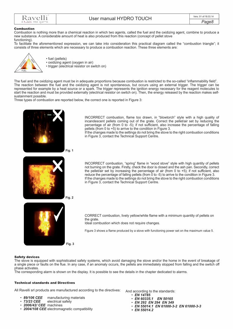
CombustionCombustion is nothing more than a chemical reaction in which two agents, called the fuel and the oxidizing agent, combine to produce a new substance. A considerable amount of heat is also produced from this reaction (concept of pellet stove functioning). To facilitate the aforementioned expression, we can take into consideration this practical diagram called the “combustion triangle”; it consists of three elements which are necessary to produce a combustion reaction. These three elements are:
• fuel (pellets)• oxidizing agent (oxygen in air)• trigger (electrical resistor on switch on)
The fuel and the oxidizing agent must be in adequate proportions because combustion is restricted to the so-called “inflammability field”.The reaction between the fuel and the oxidizing agent is not spontaneous, but occurs using an external trigger. The trigger can be represented for example by a heat source or a spark. The trigger represents the ignition energy necessary for the reagent molecules to start the reaction and must be provided externally (electrical resistor on switch on). Then, the energy released by the reaction makes self-sustainment possible. Three types of combustion are reported below, the correct one is reported in Figure 3:
INCORRECT combustion, flame too drawn, in “blowtorch” style with a high quality of incandescent pellets coming out of the grate. Correct the pellet/air set by reducing the percentage of air (from 0 to -5); if not sufficient, also increase the percentage of falling pellets (from 0 to +5) to arrive to the condition in Figure 3.If the changes made to the settings do not bring the stove to the right combustion conditions in Figure 3, contact the Technical Support Centre.
INCORRECT combustion, “spring” flame in “wood stove” style with high quantity of pellets not burning on the grate. Firstly, check the door is closed and the ash pan. Secondly, correct the pellet/air set by increasing the percentage of air (from 0 to +5); if not sufficient, also reduce the percentage of falling pellets (from 0 to -5) to arrive to the condition in Figure 3.If the changes made to the settings do not bring the stove to the right combustion conditions in Figure 3, contact the Technical Support Centre.
CORRECT combustion, lively yellow/white flame with a minimum quantity of pellets on the grate.Ideal combustion which does not require changes.
Figure 3 shows a flame produced by a stove with functioning power set on the maximum value 5.
Fig. 1
Fig. 2
Fig. 3
OXYGEN
HEAT
FUEL
Safety devicesThe stove is equipped with sophisticated safety systems, which avoid damaging the stove and/or the home in the event of breakage of a single piece or faults on the flue. In any case, if an anomaly occurs, the pellets are immediately stopped from falling and the switch off phase activates. The corresponding alarm is shown on the display. It is possible to see the details in the chapter dedicated to alarms.
Technical standards and Directives
All Ravelli srl products are manufactured according to the directives:
• 89/106 CEE manufacturing materials• 73/23 CEE electrical safety• 2006/42/ CEE machines• 2004/108 CEE electromagnetic compatibility
And according to the standards:• EN 14785• EN 60335.1 EN 50165• EN 292 EN 294 EN 349• EN 55014.1 EN 61000-3-2 EN 61000-3-3• EN 55014.2

User manual HYDRO TOUCH Page9
Vers. 01 of:18.03.14
Stove installation
Advice for installationBecause of the frequent accidents caused by the malfunctioning of the flues in residential buildings, this chapter has been draftet in collaboration with Assocosma (association of stove/sweepping technicians and specialists of the field) in order to facilitate the installer to build a system able to evacuate fumes in accordance with the regulations in force.
- Marking standard Directive CE 89/106 D.P.R. 246 regarding the exclusive use of CE certified material;- UNI 10683/2012 for the installation of a biomass fire box;- UNI/TS 11278 regarding the selection of material (only for pellet stoves different than V2)- UNI 10845 (excerpt from gas-related regulations) for piping with the relative control of the skylight well (material used, state of wear
etc.) and safety dstances to be observed from combustible materials;- UNI 7129/08 (standards regarding depressurized chimneys, excerpt from gas-related regulations) regarding the type, height and
positioning of chimney terminal;- UNI/EN 1443 regarding the installation with the minimum essential chimney requirements met (followed by the compilation of fume
dataplate to be affixed to the chimney).
Approved installations Fireplaces, stoves and barbecues cannot be installed in areas in which are present and functioning equipment fueled by liquid and gas type A and type B (for classification see UNI 10642 and UNI 7129).It is forbidden to install the stove in rooms used for cooking, if there are:- collective type ventilation ducts;- blowers/vacuums connected to the outside and/or equipment that can depressurize the room.It is forbidden to install the stove in rooms at risk of fire such as garages and garages, bedrooms (only watertight installation) orstudios (unless installed in a hermetically sealed combustion chamber).
EXCERPT OF STANDARD UNI/EN 1443
System compatibility checkCompatibility check of the system should be carried out before any installation or commissioning intervention.The adjacent, side and rear walls and the supporting surface must be made of non-combustible and non sensitive to heat material.Installation next to combustible materials or heat-sensitive materials is allowed provided that suitable protection is ensured with insulating and non-combustible materials. This should however be provided by the manufacturer's instructions.When the installation instructions are not available, the installer will have to secure the appliance and shall be liable for its commissioning.Before installation you should check the position of the stove, flue or exhaust terminal devices to make sure the following have been observed:- Installation restrictions- Legal distances- Limitations provided by local administrative regulations or specific provisions of the local bodies.- Conventional limitations imposed by the residence regulations, easement or contracts.
After surveying the installation place, the installer should check the following:- the type of appliance;- the compatitbility of the installation place with the appliance in terms of minimum installation volume indicated by the
manufacturer;- the instructions of the manufacturer of the heat generator regarding the requirements of the fume exhaust system in case the
generator is not working;- the internal cross section of the fume duct, the composing materials, the evenness of the cross section, the absence of
obstructions;- height and length on vertical plane of the chimney;- the existence and compliance of chimney terminal;- the possibility to fit external air vents and the dimensions of existing vents.
The complete flue exhaust system must be supplied and installed in compliance with the regulations issued by the standardization bodies and should be installed according to state-of-the-art standards.
Air ventIt is used to fuel the fire box and input air into the room; it should be fitted directly from the outside (not through other rooms, garage etc.; its cross section should be equal or 1/4 higher than chimney section by minimum 80 sq.cm for stoves and thermo-stoves (UNI1475) and 100 sq. cm for boilers (UNI303-5).Manufacturer's and designer's instructions should be however complied with at all times. Also check that the drilling position of the wall allows the intake of fresh air, making sure that no harmful exhausts fumes return into the room (radon gas, ect.).
User manual HYDRO TOUCH Page10
Vers. 01 of:18.03.14
Fume duct and fittingsFor heat generating devices equipped with an electric fume exhaust fan you must follow the installation instructions of the manufacturer regarding the maximum length and number of bends of the exhaust ducts.In case the maximum values are not available , you should follow the provisions below:- Horizontal sections should have a minimum slope of 3% upwards (45° bends are recommended)- The length of the horizontal section should be minimum and its plan projection should not exceed 3 metres- The number of direction changes including the one required to use the T fitting and insert the chimney should not be higher than 3.- This section should have constant diameter and equal at fire box outlet up to the fitting into the flue.- It is forbidden to use flexible metal and cement fibre tubes and pressurization should be ensured at all timesIn any case, the fume ducts should be sealed and protected against combustion products or condenstae as well as insulated ifpassing outside the installation room.It is not allowed to mount manually regulated draught devices onto appliances with forced draught.
Flue
- It should be made of suitable materials to ensure resistance to normal mechanical and chemical stress, and be properly insulatedto prevent the formation of condensate; it should, therefore, be insulated (flue standard UNI 1856 |1|2 and used materials standardUNI/TS 11278)
- Be free of narrowing throughout its length;- Be properly spaced by means of air gaps and insulated with non flammable materials.- Maximum bends allowed are at 45°.- the flue installed inside the house should be insulated and can be inserted into a chimney terminal as long as the piping standards
are being complied with (UNI 10845).- The fume duct should be connected to the chimney by means of a T fitting with a collection chamber fitted with inspection glass to
check the combustion residues and condensate collection.
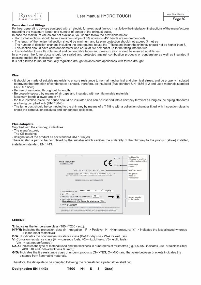
Flue dataplateSupplied with the chimney, it identifies:- The manufacturer;- The CE marking;- designation of the product as per standard UNI 1856(xx)There is also a part to be completed by the installer which certifies the suitability of the chimney to the product (stove) installed,installation standard EN 1443.
Last two digits of the year in which the marking has been affixed
Identification number
Certificate number
Designation stated by manufacturer
Section compiled by the installer
EN 1856/1-2 T400 N1 D v2 l50050 G(30)
T400 N1 D 3 G(30)100
30
Mario Bianchi Via Rossi 24 Calcinate (BG)27/07/2011
LEGEND:
T: Indicates the temperature class (T80 - T200 - etc.);N/P/H: Indicates the protection class (N-->negative - P--> Positive - H-->High pressure; “x”--> indicates the loss allowed whereas
1 is the most restrictive);D/W: It indicates the condenstae resistance class (D-->for dry use - W-->for wet use);V: Corrosion resistance class (V1-->gaseous fuels; V2-->liquid fuels; V3-->solid fuels; Vm--> test not performed);LX/X: Indicates the type of material used and the thickness in hundredths of millimetres (i.g.: L50050 indicates L50-->Stainless Steel AISI 316 and 050-->thickness 0.5mm);G/O: Indicates the fire resistance class of unburnt products (G-->YES; O-->NO) and the value between brackets indicates the
distance from flammable materials.
Therefore, the dataplate to be compiled following the requests for a pellet stove shall be:
Designation EN 1443: T400 N1 D 3 G(xx)

User manual HYDRO TOUCH Page11
Vers. 01 of:18.03.14
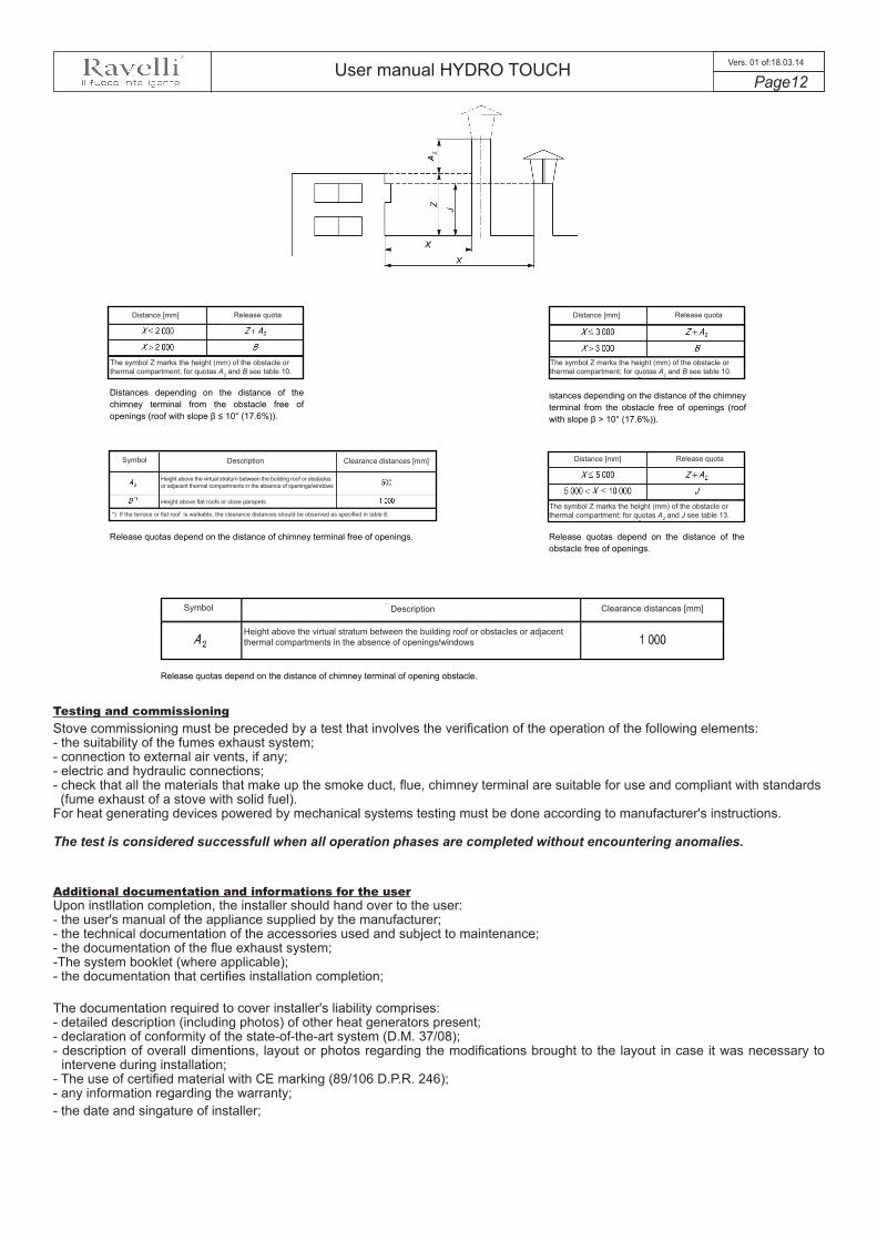
Chimney terminal (UNI 7129/08):- Fume exhaust cross section should be twice the diameter of the chimney;- Have a structure suitable to prevent water or snow from entering;- Be built so that in the presence of wind it still ensures fume exhaust
(wind-proof chimney cap)- Function always as a static suction system facilitating fume dispersion- the release quota is measured between the lower covering layer and the
lower point of the fume release into environment, ouside the reflux area toprevent counter-pressures;
- Be built at safe distance from antennas or parabolic antennas never beused as a support;
Safe distances for proper installation of chimney terminal:
IT IS FORBIDDEN TO DISCHARGE FLUES THROUGH A DIRECT SYSTEM OR ANY OTHER DRAIN SYSTEM NOT PROVIDED BY THE STANDARDS MENTIONED ABOVE
The pellet stoves have the flue system working with negative pressure (see LH and RH side of the roof) the part marked with gray is the reflux area and the chimney terminal should therefore release the fume above these area.
Usable section of chimney terminal outlet
Internal chimney section
Flue system working with negative pressure
Symbol
Symbol
Symbol
Dormer window(2) Side distance from dormer window
Front distance from dormer window
Height above openings or windows
Distance from the smaller line of openings or windows
Height above the ridge of dormer window frame
Skylight (1)
Description
Description[mm]
Description Clearance area [mm]
Distance measured at 90o from roof surface
Height above roof ridge
Height measured in vertical plane
Height above the obstacle
Distance from top or side line of openings and windows
(See figure 8)
Clearance area [mm]
Release area [mm]
Flue system working with positive pressure
User manual HYDRO TOUCH Page12
Vers. 01 of:18.03.14
Distances depending on the distance of the chimney terminal from the obstacle free of openings (roof with slope β ≤ 10° (17.6%)).
istances depending on the distance of the chimney terminal from the obstacle free of openings (roof with slope β > 10° (17.6%)).
Release quotas depend on the distance of chimney terminal free of openings. Release quotas depend on the distance of the obstacle free of openings.
Release quotas depend on the distance of chimney terminal of opening obstacle.
Testing and commissioningStove commissioning must be preceded by a test that involves the verification of the operation of the following elements:- the suitability of the fumes exhaust system;- connection to external air vents, if any;- electric and hydraulic connections;- check that all the materials that make up the smoke duct, flue, chimney terminal are suitable for use and compliant with standards(fume exhaust of a stove with solid fuel).
For heat generating devices powered by mechanical systems testing must be done according to manufacturer's instructions.
The test is considered successfull when all operation phases are completed without encountering anomalies.
Additional documentation and informations for the userUpon instllation completion, the installer should hand over to the user:- the user's manual of the appliance supplied by the manufacturer;- the technical documentation of the accessories used and subject to maintenance;- the documentation of the flue exhaust system;-The system booklet (where applicable);- the documentation that certifies installation completion;
The documentation required to cover installer's liability comprises:- detailed description (including photos) of other heat generators present;- declaration of conformity of the state-of-the-art system (D.M. 37/08);- description of overall dimentions, layout or photos regarding the modifications brought to the layout in case it was necessary to
intervene during installation;- The use of certified material with CE marking (89/106 D.P.R. 246);- any information regarding the warranty;- the date and singature of installer;
Distance [mm]
Symbol
Symbol
Description
Description
Clearance distances [mm]
Clearance distances [mm]
Distance [mm]
Distance [mm]
The symbol Z marks the height (mm) of the obstacle or thermal compartment; for quotas A2 and B see table 10.
Height above the virtual stratum between the building roof or obstacles or adjacent thermal compartments in the absence of openings/windows
Height above flat roofs or close parapets
*) If the terrace or flat roof is walkable, the clearance distances should be observed as specified in table 8.
Height above the virtual stratum between the building roof or obstacles or adjacent thermal compartments in the absence of openings/windows
The symbol Z marks the height (mm) of the obstacle or thermal compartment; for quotas A2 and B see table 10.
The symbol Z marks the height (mm) of the obstacle or thermal compartment; for quotas A2 and J see table 13.
Release quota Release quota
Release quota
User manual HYDRO TOUCH Page13
Vers. 01 of:18.03.14
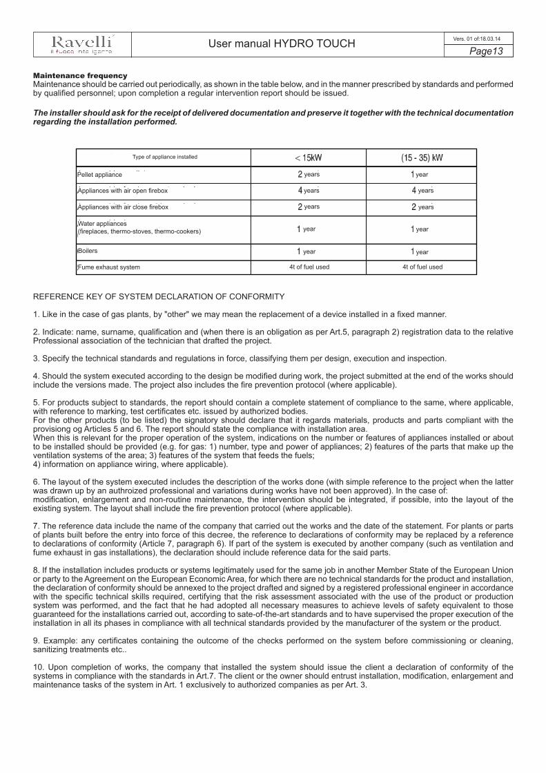
Maintenance frequencyMaintenance should be carried out periodically, as shown in the table below, and in the manner prescribed by standards and performed by qualified personnel; upon completion a regular intervention report should be issued.
The installer should ask for the receipt of delivered documentation and preserve it together with the technical documentation regarding the installation performed.
REFERENCE KEY OF SYSTEM DECLARATION OF CONFORMITY
1. Like in the case of gas plants, by "other" we may mean the replacement of a device installed in a fixed manner.
2. Indicate: name, surname, qualification and (when there is an obligation as per Art.5, paragraph 2) registration data to the relativeProfessional association of the technician that drafted the project.
3. Specify the technical standards and regulations in force, classifying them per design, execution and inspection.
4. Should the system executed according to the design be modified during work, the project submitted at the end of the works shouldinclude the versions made. The project also includes the fire prevention protocol (where applicable).
5. For products subject to standards, the report should contain a complete statement of compliance to the same, where applicable,with reference to marking, test certificates etc. issued by authorized bodies.For the other products (to be listed) the signatory should declare that it regards materials, products and parts compliant with theprovisiong og Articles 5 and 6. The report should state the compliance with installation area.When this is relevant for the proper operation of the system, indications on the number or features of appliances installed or aboutto be installed should be provided (e.g. for gas: 1) number, type and power of appliances; 2) features of the parts that make up theventilation systems of the area; 3) features of the system that feeds the fuels;4) information on appliance wiring, where applicable).
6. The layout of the system executed includes the description of the works done (with simple reference to the project when the latterwas drawn up by an authroized professional and variations during works have not been approved). In the case of:modification, enlargement and non-routine maintenance, the intervention should be integrated, if possible, into the layout of theexisting system. The layout shall include the fire prevention protocol (where applicable).
7. The reference data include the name of the company that carried out the works and the date of the statement. For plants or partsof plants built before the entry into force of this decree, the reference to declarations of conformity may be replaced by a referenceto declarations of conformity (Article 7, paragraph 6). If part of the system is executed by another company (such as ventilation andfume exhaust in gas installations), the declaration should include reference data for the said parts.
8. If the installation includes products or systems legitimately used for the same job in another Member State of the European Unionor party to the Agreement on the European Economic Area, for which there are no technical standards for the product and installation,the declaration of conformity should be annexed to the project drafted and signed by a registered professional engineer in accordancewith the specific technical skills required, certifying that the risk assessment associated with the use of the product or productionsystem was performed, and the fact that he had adopted all necessary measures to achieve levels of safety equivalent to thoseguaranteed for the installations carried out, according to sate-of-the-art standards and to have supervised the proper execution of theinstallation in all its phases in compliance with all technical standards provided by the manufacturer of the system or the product.
9. Example: any certificates containing the outcome of the checks performed on the system before commissioning or cleaning,sanitizing treatments etc..
10. Upon completion of works, the company that installed the system should issue the client a declaration of conformity of thesystems in compliance with the standards in Art.7. The client or the owner should entrust installation, modification, enlargement andmaintenance tasks of the system in Art. 1 exclusively to authorized companies as per Art. 3.
Type of appliance installed
Pellet appliance
Appliances with air open firebox
Appliances with air close firebox
Boilers
years
years years
yearsyears
year
year
year
yearyear
Fume exhaust system 4t of fuel used 4t of fuel used
Water appliances(fireplaces, thermo-stoves, thermo-cookers)
User manual HYDRO TOUCH Page14
Vers. 01 of:18.03.14
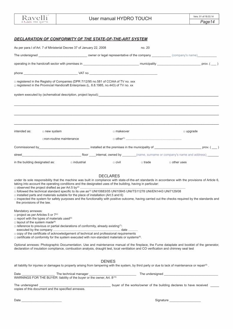
DECLARATION OF CONFORMITY OF THE STATE-OF-THE-ART SYSTEM
As per para.I of Art. 7 of Ministerial Decree 37 of January 22, 2008 no. 20
The undersigned ____________________________ owner or legal representative of the company ___________ (company's name)___________
operating in the handcraft sector with premises in ________________________________ municipality _________________________ prov. ( ___ )
phone _______________________________ VAT no _______________________________________
□ registered in the Registry of Companies (DPR 7/12/95 no.581 of CCIAA of TV no. xxx□ registered in the Provincial Handicraft Enterprises (L. 8.8.1985, no.443) of TV no. xx
system executed by (schematical description, project layout):_______________________________________________________
______________________________________________________________________________________________
______________________________________________________________________________________________
______________________________________________________________________________________________
intended as: □ new system □ makeover □ upgrade
□non-routine maintenance □ other(1) ................................................................
Commissioned by_____________________________ installed at the premises in the municipality of ___________________________ prov. ( ___ )
street__________________________________ floor ____internal, owned by ________(name, surname or company's name and address)_______
in the building designated as: □ industrial □ civil □ trade □ other uses
DECLARESunder its sole responsibility that the machine was built in compliance with state-of-the-art standards in accordance with the provisions of Article 6, taking into account the operating conditions and the designated uses of the building, having in particular:□ observed the project drafted as per Art.5 by(2) .........................................................................................................................□ followed the technical standard specific to its use as(3) UNI10683/05 UNI10845 UNI/TS11278 UNI/EN1443 UNI7129/08□ installed parts and materials suitable for the place of installation (Art.5 and 6)□ inspected the system for safety purposes and the functionality with positive outcome, having carried out the checks required by the standards and
the provisions of the law.
Mandatory annexes:□ project as per Articles 5 or 7(4)
□ report with the types of materials used(5)
□ layout of the system made(6)
□ reference to previous or partial declarations of conformity, already existing(7): executed by the company ............................................................................. date ...........□ copy of the certificate of acknowledgement of technical and professional requirements□ certificate of conformity for the system executed with non-standard materials or systems(8).
Optional annexes: Photographic Documentation. Use and maintenance manual of the fireplace, the Fume dataplate and booklet of the generator, declaration of insulation compliance, combustion analysis, draught test, local ventilation and CO verification and chimney seal test
DENIESall liability for injuries or damages to property arising from tampering with the system, by third party or due to lack of maintenance or repair(9) .
Date ___________________ The technical manager ___________________________ The undersigned _______________________________WARNINGS FOR THE BUYER: liability of the buyer or the owner, Art. 8(10)
The undersigned _________________________________________ buyer of the works/owner of the building declares to have received _____ copies of this document and the specified annexes.
Date _______________________ Signature __________________
User manual HYDRO TOUCH Page15
Vers. 01 of:18.03.14
Smoke duct:use of non insulated tube
T-fitting
Insulated flue
Protection from rain
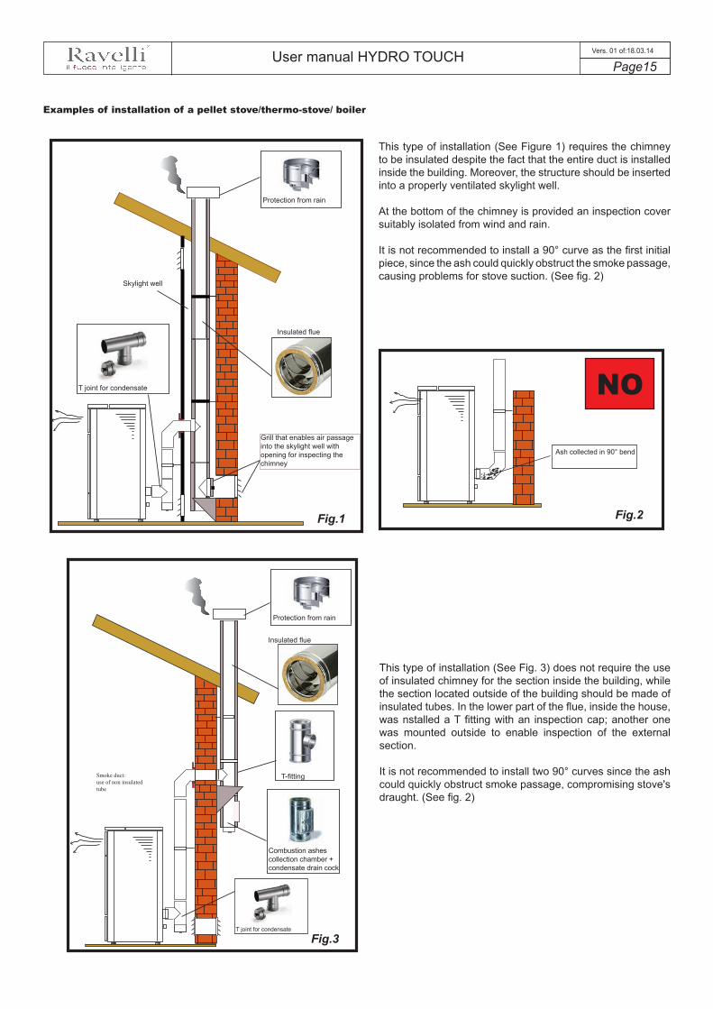
This type of installation (See Figure 1) requires the chimney to be insulated despite the fact that the entire duct is installed inside the building. Moreover, the structure should be inserted into a properly ventilated skylight well.
At the bottom of the chimney is provided an inspection cover suitably isolated from wind and rain.
It is not recommended to install a 90° curve as the first initial piece, since the ash could quickly obstruct the smoke passage, causing problems for stove suction. (See fig. 2)
Fig.2Fig.1
This type of installation (See Fig. 3) does not require the use of insulated chimney for the section inside the building, while the section located outside of the building should be made of insulated tubes. In the lower part of the flue, inside the house, was nstalled a T fitting with an inspection cap; another one was mounted outside to enable inspection of the external section.
It is not recommended to install two 90° curves since the ash could quickly obstruct smoke passage, compromising stove's draught. (See fig. 2)
Ash collected in 90° bend
NO
Fig.3
Examples of installation of a pellet stove/thermo-stove/ boiler
Protection from rain
T joint for condensate
Grill that enables air passage into the skylight well with opening for inspecting the chimney
Skylight well
T joint for condensate
Insulated flue
Combustion ashes collection chamber + condensate drain cock

User manual HYDRO TOUCH Page16
Vers. 01 of:18.03.14
INTE
RN
AL
FLU
E
This type of installation (see Figure 4) requires insulated chimney since the entire smoke duct was assembled inside the house.In the lower part of the flue was fitted a T fitting with inspection plug.
It is not recommended to install a 90° curve as the first initial piece, since the ash could quickly obstruct the smoke passage, causing problems for stove suction. (See Fig.2)
Fig.4
This type of installation (See Fig. 5) does not require an insulated flue, since part of the smoke duct was assembled inside the home and part inside an existing flue.In the lower part of the stove was intalled a T fitting with inspection plug, like for the inner part of the flue.
It is not recommended to install a 90° curve as the first piece, since the ash could quickly obstruct the smoke passage, compromising stove draught. (See Fig.2)
Fig.5
Protection from rain
Insulated flue
Protection from rain
Cover slab
Watertight steel sheeting
Inspection door
T fitting with collec-tion chamber and condensate drain
T fitting with collection and condensate chamber

User manual HYDRO TOUCH Page17
Vers. 01 of:18.03.14
This type of installation (Fig.6) requires a horizontal section for connection to an existing flue. Comply with the slope indicated in the figure, to reduce depositing ash in the horizontal tube section. In the lower part of the flue, was installed a T fitting with inspection plug like for the flue inlet.
It is not recommended to install a 90° curve as the first piece, since the ash could quickly obstruct the smoke passage, compromising stove draught. (See Fig.2)
max
2 -
3 m
Hei
ght o
ver 4
m
Slope 3 - 5 %
2-3 m Max
INTE
RN
AL
FLU
E
Fig.6
T joint for condensate
Inspection door
Protection from rain
IT IS MANDATORY TO USE WATERTIGHT PIPES WITH SILICONE SEALS.

User manual HYDRO TOUCH Page18
Vers. 01 of:18.03.14
Examples of installation of a pellet stove/thermostove/ insert
In this type of installation we can notice that the fitting was used to enable connecting the insert to the chimney (so-called "bayonet" mount).
For safety reasons and to ensure proper operation, we recommend you fit pipes into the chimney. (Fig.7)
It is recommended to perfectly match the insert with the fitting, to prevent leaks of smoke during the work phase.
Fig.7
Fig.8
Exploded view of T fitting
Here you can see the possibility to slide the insert; this operation can only be performed with the stove turned off for loading pellets or during regular checks. (Fig.8)
IT IS STRICTLY FORBIDDEN TO REMOVE THE STOVE DURING THE WORK PHASES; THE FUME MAY DISPERSE INTO THE ENVIRONMENT.
Pipe
Pipe
Flue
Flue
T fitting with inspection ash collector cap
Protection from rain
Protection from rain

User manual HYDRO TOUCH Page19
Vers. 01 of:18.03.14
Hydraulic installation
Safety devices for open tank systemAccording to the standard UNI 10412-2 (2006) in force in Italy, the systems with an open expansion tank must be equipped with:
• Open expansion tank• Safety tube• Loading tube• Circulator command thermostat (excluded for natural circulation systems)• Circulation system (excluded for natural circulation systems)• Acoustic alarm activation device• Acoustic alarm• Temperature indicator• Pressure indicator• Automatic blocking thermal switch (blocking thermostat)
Safety devices for closed tank system According to the standard UNI 10412-2 (2006) in force in Italy, closed systems must be equipped with:
• Safety valve• Circulator command thermostat• Acoustic alarm activation thermostat• Temperature indicator• Pressure indicator• Acoustic alarm• Automatic regulation thermal switch• Automatic blocking thermal switch (blocking thermostat)• Circulation system• Expansion system• Safety dissipation system built into the generator with thermal safety valve (self-activated), in case the the equipment is not provided
with an automatic temperature regulation system.The appliances for domestic heating with automatic feeding system must be equipped with a block thermostat for the fuel or with a cooling circuit provided by the manufacturer of the device, activated by a thermal safety valve that ensures that the compliant temperature threhold set is not exceeded. Connection between the power supply unit and the valve must be without shut-offs. Pressure upstream of the cooling circuit must at least be 1.5 bar.
Installation adviceAfter placing the boiler and installing all fume exhaust pipes, you can connect the hydraulic system. It is recommended to connect the boiler to the system by means of ball valves or gate valves, in order to enable easy detachment, if needed. Before connection we strongly recommend you carry out a thorough cleaning of the system. We recommend that you connect the vent of the safety valve through a special pipe in order to prevent damage in case of overpressure or increase in temperature.
PLUMBING MUST ALWAYS BE CARRIED OUT BY QUALIFIED PERSONNEL, ABLE TO CARRY OUT A STATE-OF-THE-ART INSTALLATION IN COMPLIANCE WITH THE LAWS IN FORCE IN THE COUNTRY OF INSTALLATION, AFTER HAVING READ THE NEXT CHAPTER. RAVELLI DENIES ALL LIABILITIES FO DAMAGES TO PEOPLE OR PROPERTY ARISING FROM MALFUNCTIONS DUE TO FAILURE TO COMPLY WITH THIS WARNING
When filling the boiler, check that the Jolly valve (picture on the left) is working properly by venting the system. The maximum Loading pressure with COLD water should be of 1 bar. In order to ensure proper operation with HOT water, the pressure in the stove should be 1.5 bar. For installation of an additional expansion tank, remember that normally 1 litre of expansion tank compensates 10 litres of the system and at least two litres are always dedicated to the water inside the stove.
FILLING MUST BE CARRIED OUT USING A “T“ JOINT PLACED ON THE HEATING SUPPLY, LOADING TO A MAXIMUM OF 1 BAR WITH COLD WATER PERIODICALLY CHECK ON THE CONTROL CONSOLES THE PRESSURE IN THE STOVE, AND KEEP IT STEADY AT 1 BAR.
Correctly connect the stove to the hydraulic system, bringing pressure of the system to 0.8 or max 1 bar when the stove has not yet been switched on (in the event the system is not a closed tank system, but has an open tank, it is necessary to change the setting on the menu, which is reserved to authorised technician). Now proceed to bleed the hydraulic system using the valve assembled on the boiler or using the valves assembled on the radiators. This operation can be carried out multiple times, even after activation of the boiler since, from the time the temperature of the water starts to increase, the air bubbles move towards the high part of the boiler. Once you have completed this operation, close the feeding valve.
While bleeding the boiler, ensure the electrical parts near the valve are not wet!In the event this occurs, do not turn on the boiler, but proceed to dry the electronic board using a hairdryer.
THE HYDRAULIC CONNECTION PROVIDES EXCLUSIVELY THE PRESENCE OF OUR CIRCULATOR INTO THE STOVE AT SYSTEM RETURN LINE. REFER TO THE DEDICATED SECTION TO SEE HOW TO CONNECT EVERY SINGLE MODEL.

User manual HYDRO TOUCH Page20
Vers. 01 of:18.03.14
Examples of hydraulic installationThe diagrams below show the various types of connection with existing plants or new plants that are electronically controlled by Ravelli stove. To carry out the connection correctly, always follow the instructions of the plumber. The hydraulic system must comply with the local regulations in force. The installation and checks should be performed exclusively by qualified and authorized staff that certifies the installation.Direct circuit to the system
Pelle
t boi
ler
Dis
trib
utio
n he
atin
g co
llect
ors
Radi
ator
sTh
erm
omet
erM
anom
eter
Ant
i-con
dens
atio
n va
lve
Non
-ret
urn
valv
eD
irect
dis
trib
utio
n un
itTh
erm
osta
tic d
istr
ibut
ion
unit
Radi
atin
g pa
nel (
�oor
hea
ting)
Shut
-o�
valv
esA
mbi
ent t
herm
osta
t
Are
a 1
Are
a 2
This
type
of i
nsta
llatio
n en
able
s co
nnec
ting
the
stov
e to
the
exis
ting
syst
em, h
eatin
g th
e en
tire
build
ing.
In a
dditi
on, t
here
is th
e po
ssib
ility
to c
ontro
l gen
erat
or a
ctiv
atio
n by
mea
ns o
f the
loca
l the
rmos
tats
, pro
vidi
ng
the
use
of a
n ad
ditio
nal b
oard
that
can
be
foun
d at
Ret
aile
rs a
utho
rized
by
Rav
elli.
User manual HYDRO TOUCH Page21
Vers. 01 of:18.03.14
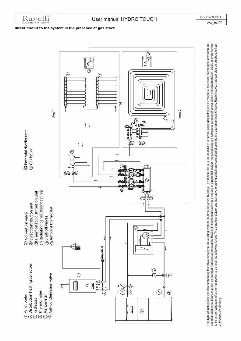
Direct circuit to the system in the presence of gas stovePe
llet b
oile
rD
istr
ibut
ion
heat
ing
colle
ctor
sRa
diat
ors
Ther
mom
eter
Man
omet
erA
nti-c
onde
nsat
ion
valv
e
Non
-ret
urn
valv
eD
irect
dis
trib
utio
n un
itTh
erm
osta
tic d
istr
ibut
ion
unit
Radi
atin
g pa
nel (
�oor
hea
ting)
Shut
-o�
valv
esA
mbi
ent t
herm
osta
t
Pote
ntia
l div
ider
uni
tG
as b
oile
r
Are
a 1
Aqu
educ
t
Are
a 2
This
type
of i
nsta
llatio
n en
able
s co
nnec
ting
the
stov
e di
rect
ly to
the
exis
ting
syst
em, h
eatin
g th
e en
tire
build
ing.
In a
dditi
on, t
here
is th
e po
ssib
ility
to c
ontro
l gen
erat
or a
ctiv
atio
n by
mea
ns o
f the
loca
l the
rmos
tats
, pro
vidi
ng th
e us
e of
an
addi
tiona
l boa
rd th
at c
an b
e fo
und
at R
etai
lers
aut
horiz
ed b
y R
avel
li. In
this
layo
ut is
pro
vide
d th
e us
e of
a p
oten
tial d
ivid
er (n
o.13
) to
ensu
re a
cor
rect
sep
arat
ion
of p
ower
with
in th
e sy
stem
(DM
1/12
/75)
, to
avoi
d ha
ving
to
lie
in th
e re
aliz
atio
n of
a th
erm
al p
ower
to a
chie
ve th
e fo
llow
ing
layo
ut. T
he p
oten
tial d
ivid
er a
nd g
as s
tove
ena
blin
g sw
itch
are
cont
rolle
d di
rect
ly b
y th
e op
erat
ion
logi
c of
eve
ry R
avel
li st
ove,
that
can
als
o be
pur
chas
ed fr
om
auth
oriz
ed d
istri
buto
rs.

User manual HYDRO TOUCH Page22
Vers. 01 of:18.03.14
Direct connection to the system + DHW boiler in the presence of gas stove
Pelle
t boi
ler
Dis
trib
utio
n he
atin
g co
llect
ors
Radi
ator
sTh
erm
omet
erM
anom
eter
Ant
i-con
dens
atio
n va
lve
Non
-ret
urn
valv
eD
irect
dis
trib
utio
n un
itTh
erm
osta
tic d
istr
ibut
ion
unit
Radi
atin
g pa
nel (
�oor
hea
ting)
Shut
-o�
valv
esA
mbi
ent t
herm
osta
t
Expa
nsio
n ve
ssel
Sola
r pum
p un
itSo
lar c
olle
ctor
Ther
mos
tatic
mix
ing
valv
ePo
tent
ial d
ivid
er u
nit
Mot
oriz
ed th
ree-
way
val
ve
Mot
oriz
ed th
ree-
way
val
ve w
ith s
prin
g re
turn
Flow
sw
itch
Stor
age
tank
boi
ler
Gas
boi
ler
Are
a 1
Are
a 2
Aqu
educ
t
This
type
of c
onne
ctio
n en
able
s co
nnec
ting
the
stov
e di
rect
ly to
the
exis
ting
syst
em, h
eatin
gthe
ent
ire b
uild
ing,
as
wel
l as
mee
ting
the
dem
and
of h
ot w
ater
thro
ugh
the
use
of a
boi
ler.
In a
dditi
on, t
here
is th
e po
ssib
ility
to
cont
rol g
ener
ator
act
ivat
ion
by m
eans
of t
he lo
cal t
herm
osta
ts, p
rovi
ding
the
use
of a
n ad
ditio
nal e
xpan
sion
boa
rd th
at c
an b
e fo
und
at R
etai
lers
aut
horiz
ed b
y R
avel
li. In
this
layo
ut is
pro
vide
d th
e us
e of
a p
oten
tial d
ivid
er
(no.
13) t
o en
sure
a c
orre
ct s
epar
atio
n of
pow
er w
ithin
the
syst
em (D
M1/
12/7
5), t
o av
oid
havi
ng to
lie
in th
e re
aliz
atio
n of
a th
erm
al p
ower
to a
chie
ve th
e fo
llow
ing
layo
ut. T
he p
oten
tial d
ivid
er a
nd g
as s
tove
ena
blin
g sw
itch
are
cont
rolle
d di
rect
ly b
y th
e op
erat
ion
logi
c of
eve
ry R
avel
li st
ove,
that
can
als
o be
pur
chas
ed fr
om a
utho
rized
dis
tribu
tors
.
User manual HYDRO TOUCH Page23
Vers. 01 of:18.03.14
Pelle
t boi
ler
Dis
trib
utio
n he
atin
g co
llect
ors
Radi
ator
sTh
erm
omet
erM
anom
eter
Ant
i-con
dens
atio
n va
lve
Non
-ret
urn
valv
eD
irect
dis
trib
utio
n un
itTh
erm
osta
tic d
istr
ibut
ion
unit
Radi
atin
g pa
nel (
�oor
hea
ting)
Shut
-o�
valv
esA
mbi
ent t
herm
osta
t
Expa
nsio
n ve
ssel
Sola
r pum
p un
itSo
lar c
olle
ctor
Ther
mos
tatic
mix
ing
valv
eRe
circ
ulat
ion
pum
pPu
�er p
ipe
in ta
nk w
ith D
HW
Mot
oriz
ed th
ree-
way
val
ve w
ith s
prin
g re
turn
Gas
boi
ler
Are
a 1
Are
a 2
Aqu
educ
t
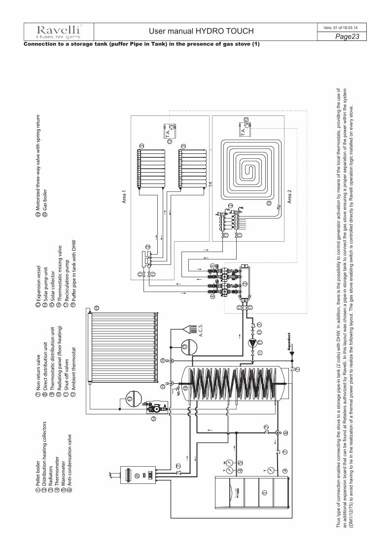
Thus
type
of c
onne
ctio
n en
able
s co
nnec
ting
the
stov
e to
a s
tora
ge p
ipe-
in ta
nk (2
coi
ls) w
ith D
HW
. In
addi
tion,
ther
e is
the
poss
ibilit
y to
con
trol g
ener
ator
act
ivat
ion
by m
eans
of t
he lo
cal t
herm
osta
ts, p
rovi
ding
the
use
of
an a
dditi
onal
exp
ansi
on b
oard
that
can
be
foun
d at
Ret
aile
rs a
utho
rized
by
Rav
elli.
In th
is la
yout
was
cho
sen
a pi
pe-in
sto
rage
tank
to c
onne
ct th
e ga
s st
ove
ensu
ring
a pr
oper
sep
arat
ion
of th
e po
wer
with
in th
e sy
stem
(D
M1/
12/7
5) to
avo
id h
avin
g to
lie
in th
e re
aliz
atio
n of
a th
erm
al p
ower
pla
nt to
real
ize
the
follo
win
g la
yout
. The
gas
sto
ve e
nabl
ing
switc
h is
con
trolle
d di
rect
ly b
y R
avel
li op
erat
ion
logi
c in
stal
led
on e
very
sto
ve.
Connection to a storage tank (puffer Pipe in Tank) in the presence of gas stove (1)
User manual HYDRO TOUCH Page24
Vers. 01 of:18.03.14
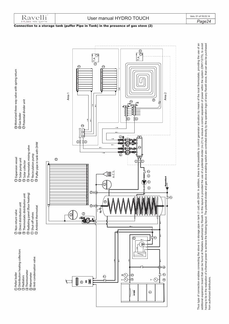
Connection to a storage tank (puffer Pipe in Tank) in the presence of gas stove (2)
Thus
type
of c
onne
ctio
n en
able
s co
nnec
ting
the
stov
e to
a s
tora
ge p
ipe-
in ta
nk (1
coi
l) w
ith D
HW
. In
addi
tion,
ther
e is
the
poss
ibilit
y to
con
trol g
ener
ator
act
ivat
ion
by m
eans
of t
he lo
cal t
herm
osta
ts, p
rovi
ding
the
use
of a
n ad
ditio
nal e
xpan
sion
boa
rd th
at c
an b
e fo
und
at R
etai
lers
aut
horiz
ed b
y R
avel
li. In
this
layo
ut is
pro
vide
d th
e us
e of
a p
oten
tial d
ivid
er (n
o.21
) to
ensu
re a
cor
rect
sep
arat
ion
of p
ower
with
in th
e sy
stem
(DM
1/12
/75)
, to
avoi
d ha
ving
to li
e in
the
real
izat
ion
of a
ther
mal
pow
er to
ach
ieve
the
follo
win
g la
yout
. The
pot
entia
l div
ider
and
gas
sto
ve e
nabl
ing
switc
h ar
e co
ntro
lled
dire
ctly
by
the
oper
atio
n lo
gic
of e
very
Rav
elli
stov
e, th
at c
an a
lso
be p
urch
ased
fro
m a
utho
rized
dis
tribu
tors
.
Pelle
t boi
ler
Dis
trib
utio
n he
atin
g co
llect
ors
Radi
ator
sTh
erm
omet
erM
anom
eter
Ant
i-con
dens
atio
n va
lve
Non
-ret
urn
valv
eD
irect
dis
trib
utio
n un
itTh
erm
osta
tic d
istr
ibut
ion
unit
Radi
atin
g pa
nel (
�oor
hea
ting)
Shut
-o�
valv
esA
mbi
ent t
herm
osta
t
Expa
nsio
n ve
ssel
Sola
r pum
p un
itSo
lar c
olle
ctor
Ther
mos
tatic
mix
ing
valv
eRe
circ
ulat
ion
pum
pPu
�er p
ipe
in ta
nk w
ith D
HW
Mot
oriz
ed th
ree-
way
val
ve w
ith s
prin
g re
turn
Gas
boi
ler
Pote
ntia
l div
ider
uni
t Are
a 1
Are
a 2
Aqu
educ
t
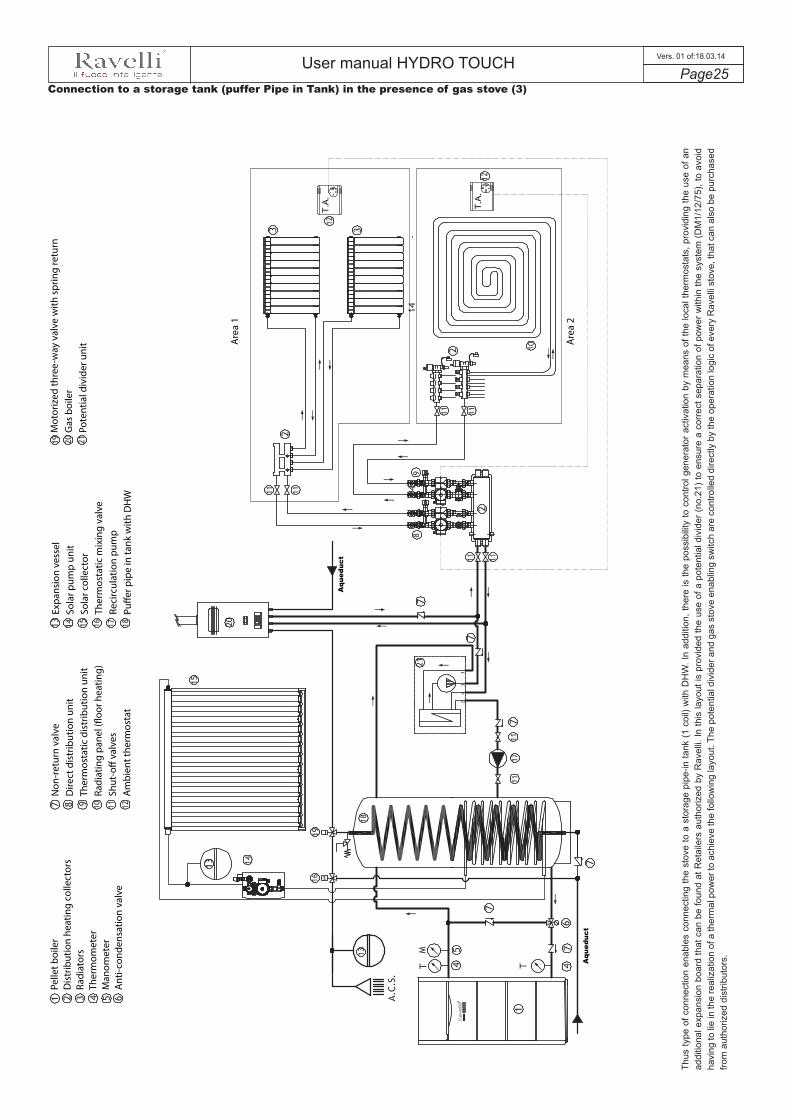
User manual HYDRO TOUCH Page25
Vers. 01 of:18.03.14
Connection to a storage tank (puffer Pipe in Tank) in the presence of gas stove (3)
Thus
type
of c
onne
ctio
n en
able
s co
nnec
ting
the
stov
e to
a s
tora
ge p
ipe-
in ta
nk (1
coi
l) w
ith D
HW
. In
addi
tion,
ther
e is
the
poss
ibilit
y to
con
trol g
ener
ator
act
ivat
ion
by m
eans
of t
he lo
cal t
herm
osta
ts, p
rovi
ding
the
use
of a
n ad
ditio
nal e
xpan
sion
boa
rd th
at c
an b
e fo
und
at R
etai
lers
aut
horiz
ed b
y R
avel
li. In
this
layo
ut is
pro
vide
d th
e us
e of
a p
oten
tial d
ivid
er (n
o.21
) to
ensu
re a
cor
rect
sep
arat
ion
of p
ower
with
in th
e sy
stem
(DM
1/12
/75)
, to
avoi
d ha
ving
to li
e in
the
real
izat
ion
of a
ther
mal
pow
er to
ach
ieve
the
follo
win
g la
yout
. The
pot
entia
l div
ider
and
gas
sto
ve e
nabl
ing
switc
h ar
e co
ntro
lled
dire
ctly
by
the
oper
atio
n lo
gic
of e
very
Rav
elli
stov
e, th
at c
an a
lso
be p
urch
ased
fro
m a
utho
rized
dis
tribu
tors
.
Pelle
t boi
ler
Dis
trib
utio
n he
atin
g co
llect
ors
Radi
ator
sTh
erm
omet
erM
anom
eter
Ant
i-con
dens
atio
n va
lve
Non
-ret
urn
valv
eD
irect
dis
trib
utio
n un
itTh
erm
osta
tic d
istr
ibut
ion
unit
Radi
atin
g pa
nel (
�oor
hea
ting)
Shut
-o�
valv
esA
mbi
ent t
herm
osta
t
Expa
nsio
n ve
ssel
Sola
r pum
p un
itSo
lar c
olle
ctor
Ther
mos
tatic
mix
ing
valv
eRe
circ
ulat
ion
pum
pPu
�er p
ipe
in ta
nk w
ith D
HW
Mot
oriz
ed th
ree-
way
val
ve w
ith s
prin
g re
turn
Gas
boi
ler
Pote
ntia
l div
ider
uni
t Are
a 1
Are
a 2
Aqu
educ
t
Aqu
educ
t

User manual HYDRO TOUCH Page26
Vers. 01 of:18.03.14
Connection to a storage tank (puffer) + DHW boiler in the presence of gas stove (1)
This
type
of c
onne
ctio
n al
low
s to
con
nect
the
boile
r to
a si
mpl
e st
orag
e ta
nk a
nd a
lso
to m
eet t
he d
eman
d of
dom
estic
hot
wat
er th
roug
h th
e us
e of
a b
oile
r. In
add
ition
, the
re is
the
poss
ibilit
y to
con
trol g
ener
ator
act
ivat
ion
by
mea
ns o
f the
loca
l the
rmos
tats
, pro
vidi
ng th
e us
e of
an
addi
tiona
l exp
ansi
on b
oard
that
can
be
foun
d at
Ret
aile
rs a
utho
rized
by
Rav
elli.
In th
is la
yout
was
use
d a
pote
ntia
l div
ider
(no.
21) t
o en
sure
a c
orre
ct s
epar
atio
n of
pow
er
with
in th
e sy
stem
(DM
1/12
/75)
, to
avoi
d ha
ving
to li
e in
the
real
izat
ion
of a
ther
mal
pow
er to
ach
ieve
the
follo
win
g la
yout
. Th
e po
tent
ial d
ivid
er a
nd g
as s
tove
ena
blin
g sw
itch
are
cont
rolle
d di
rect
ly b
y th
e op
erat
ion
logi
c of
eve
ry
Rav
elli
stov
e, th
at c
an a
lso
be p
urch
ased
from
aut
horiz
ed d
istri
buto
rs.
Pelle
t boi
ler
Dis
trib
utio
n he
atin
g co
llect
ors
Radi
ator
sTh
erm
omet
erM
anom
eter
Ant
i-con
dens
atio
n va
lve
Non
-ret
urn
valv
eD
irect
dis
trib
utio
n un
itTh
erm
osta
tic d
istr
ibut
ion
unit
Radi
atin
g pa
nel (
�oor
hea
ting)
Shut
-o�
valv
esA
mbi
ent t
herm
osta
t
Expa
nsio
n ve
ssel
Sola
r pum
p un
itSo
lar c
olle
ctor
Ther
mos
tatic
mix
ing
valv
eRe
circ
ulat
ion
pum
pSt
orag
e pu
�er
Mot
oriz
ed th
ree-
way
val
ve w
ith s
prin
g re
turn
Gas
boi
ler
Pote
ntia
l div
ider
uni
tM
otor
ized
thre
e-w
ay v
alve
Cylin
der
Flow
sw
itch
Are
a 1
Are
a 2
Aqu
educ
t
Aqu
educ
t
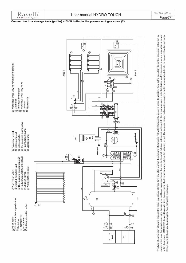
User manual HYDRO TOUCH Page27
Vers. 01 of:18.03.14
Connection to a storage tank (puffer) + DHW boiler in the presence of gas stove (2)
Pelle
t boi
ler
Dis
trib
utio
n he
atin
g co
llect
ors
Radi
ator
sTh
erm
omet
erM
anom
eter
Ant
i-con
dens
atio
n va
lve
Non
-ret
urn
valv
eD
irect
dis
trib
utio
n un
itTh
erm
osta
tic d
istr
ibut
ion
unit
Radi
atin
g pa
nel (
�oor
hea
ting)
Shut
-o�
valv
esA
mbi
ent t
herm
osta
t
Expa
nsio
n ve
ssel
Sola
r pum
p un
itSo
lar c
olle
ctor
Ther
mos
tatic
mix
ing
valv
eRe
circ
ulat
ion
pum
pSt
orag
e pu
�er
Mot
oriz
ed th
ree-
way
val
ve w
ith s
prin
g re
turn
Gas
boi
ler
Pote
ntia
l div
ider
uni
tM
otor
ized
thre
e-w
ay v
alve
Cylin
der
Flow
sw
itch
Are
a 1
Are
a 2
Aqu
educ
t
Aqu
educ
t
This
type
of c
onne
ctio
n al
low
s to
con
nect
the
boile
r to
a si
mpl
e st
orag
e ta
nk a
nd a
lso
to m
eet t
he d
eman
d of
dom
estic
hot
wat
er th
roug
h th
e us
e of
a b
oile
r. In
add
ition
, the
re is
the
poss
ibilit
y to
con
trol g
ener
ator
act
ivat
ion
by
mea
ns o
f the
loca
l the
rmos
tats
, pro
vidi
ng th
e us
e of
an
addi
tiona
l exp
ansi
on b
oard
that
can
be
foun
d at
Ret
aile
rs a
utho
rized
by
Rav
elli.
In th
is la
yout
was
use
d a
pote
ntia
l div
ider
(no.
21) t
o en
sure
a c
orre
ct s
epar
atio
n of
pow
er
with
in th
e sy
stem
(DM
1/12
/75)
, to
avoi
d ha
ving
to li
e in
the
real
izat
ion
of a
ther
mal
pow
er to
ach
ieve
the
follo
win
g la
yout
. The
pot
entia
l div
ider
and
gas
sto
ve e
nabl
ing
switc
h ar
e co
ntro
lled
dire
ctly
by
the
oper
atio
n lo
gic
of e
very
R
avel
li st
ove,
that
can
als
o be
pur
chas
ed fr
om a
utho
rized
dis
tribu
tors
.

User manual HYDRO TOUCH Page28
Vers. 01 of:18.03.14
Wiring
Connect the power cord to the back of the stove and then to a wall socket. The I/O switch in the figure should be set to I to power the stove. If voltage is not supplied check the state of the fuse installed in the box below the switch (4A fuse). During the periods of inactivity, we recommend you disconnect the power cord of the stove.
Preliminary Operations
Make sure you have removed all parts that pose the risk of burns from the combustion chamber or glass (various instructions or stickers).Before turning on the stove, make sure you have fitted the grate on the support base and check that the door and the ash drawer are properly close.
What to check befor turning on the stove
Fuel supply consists in the insertion of pellets from the top of the stove, by opening the door. During pellet loading prevent the pellet bag from coming into contact with hot surfaces.
How to load the pellets
NEVER INSERT INTO THE TANK OTHER KIND OF FUEL OTHER FROM THE PELLETS COMPLYING WITH THE SPECIFICATIONS BELOW
The control panel of your Ravelli stove consists of a "touch screen" display with selectable areas, a middle ON/OFF button (its color varies according to operating conditions) and two selection keys UP/DOWN (A and B in the bottom page figure).
Description of control panel
8 AREE SELEZIONABILI
The information below will allow you to become familiar with the product and achieve the best performance.
When powering the stove, before switching to save light - EASY condition (as shown in the picture below), the first page displays the Ravelli logo for a few seconds and the version of the firmware installed.
The displayed value indicates the currently detected temperature of water in the stove; the setting can be changed using the buttons A and B. The stove can be switched ON/OFF by pressing the middle key C FOR A FEW SECONDS.
BA
C
Press the icon to access the various functions available (stand-by condition).Note: the display returns to save light mode if you do not select other functions within the next 15 seconds.
Display in “SAVE LIGHT” mode
The appearance of the message “ADJUST THE RDS SYSTEM” indicates that the initial parameter testing procedure and calibration has been unsuccessfully. This indication does not block the stove.
The key identified by letter "C" has the task of turning the stove ON and OFF as well as resetting the alarms; they key has backlight with variable colors; its colour depends on the state of the stove, as well as the background colour of the console. For further information please refer to the table dedicated to operation phases.

User manual HYDRO TOUCH Page29
Vers. 01 of:18.03.14
2
3
4
5
1
7
8
9
10
6
(1) - Double function: to: a: indicates the temperature of H2O in the stove and the parameter set;b: by pressing the icon you will display the settings at point (8) that can be changed using the UP/DOWN
keys. (A and B described above);
(2) - Icon that shows the position of the 3-way valve:
Radiators (heating or puffers, if Evolved Layouts setting is enabled);
Domestic hot water (DHW or boiler, if Evolved Layouts setting is enabled);
(3) - Icon that shows the H2O circulator of the stove; when rotating, it indicates that the circulator is active;
(4) - Area that indicates that several icons are alternating:
It shows that the contact of the external thermostat (if active - see the section dedicated to activation) is open;
It shows that the contact of the external thermostat is close (thermostat within set limits);
It shows that the winter function is active (default settings - see the section dedicated to SEASON)
It indicates that SUMMER function is active (it can only be activated if there is a boiler function enabled)
A flashing animation is displayed showing the activity of the cleaner (if present and under certain conditions such as SHUTDOWN - ECO STOP - ALARMS - GRATE CLEANING)
(5) - Graphical icon accompanied by the line that indicates the current state of th stove (9).N.B.: The sequence of the states appears in several parts of the manual and is always identified by the relative icon.
(6) - by pressing it, you will have access to the “SET AIR/PELLET” function (see the section dedicated to the next function);
(7) - by pressing it, you will have access to the “STOVE STATE” (see the section dedicated to the next function);
(10) - by pressing it, you will have access to the “USER MENU” (see the section dedicated to the next function);
Not all the icons can be selected. Therefore, please remember that the touch screen display has 8 selectable areas as shown above. Moreover, when we refer to "press" in this manual, it should always be intended as the touch of your fingertip as shown in the picture.
Sequence of operations to be carried out
Access the user menu from the “STAND BY” page by pressing the icon. The following page will be dsiplayed
Display in “STAND BY”
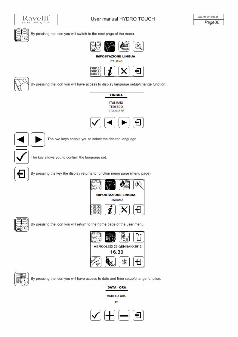
User manual HYDRO TOUCH Page30
Vers. 01 of:18.03.14
By pressing the icon you will have access to display language setup/change function.
The two keys enable you to select the desired language.
The key allows you to confirm the language set.
By pressing ths key the display returns to function menu page (menu page).
By presisng the icon you will switch to the next page of the menu.
By presisng the icon you will return to the home page of the user menu.
By pressing the icon you will have access to date and time setup/change function.

User manual HYDRO TOUCH Page31
Vers. 01 of:18.03.14
The keys allow you to increase or decrease the hour, the minutes, the day of the calendar, the month, the year and the weekday.
The key enables confirming every single parameter/change made.
By pressing ths key the display returns to function menu page (menu page).
By pressing this key, the display returns to “STAND BY” page.
By pressing on the icon you will start screw rotation upon first stove start-up and every time the tank is empty of pellets due to a previous "Out of pellets" warning signal.
Upon the completion of the previous operation, if this key is pressed, the display returns to “STAND BY” mode
If you press this icon you will access the "STOVE STATUS" page
Make sure you have inserted pellets into the tank and wait for the stove to reach the "SHUTDOWN" or "FINAL CLEANING" status. The number expressed in seconds indicates the rotation time of the infeed screw during the first loading cycle. Once this time has elapsed, the infeed screw stops immediately and then pellets are emptied from the grate before turning on the equipment.
MAKE SURE YOU ALWAYS EMPTY THE GRATE BEFORE TURNING ON THE STOVE AND CHECK THAT ALL ITS HOLES ARE FREE OF OBSTRUCTIONS. NEVER EMPTY THE GRATE INTO THE HOPPER. FIRE HAZARD.

User manual HYDRO TOUCH Page32
Vers. 01 of:18.03.14
Press the key to turn on the stove. On display appears the writing "START". If this key is pressed for a few seconds, the stove shuts down and alarms are reset.
Once the pellet loading operation is completed, press the two buttons to set the most suitable H2O value for your stove. In top left side of the previous picture (“STAND BY” status) is always possible to display both the current status and the set value.
Turning the device on
In case the infeed screw operations decsribed avobe have not been executed, the stove may fail to turn on. In this case, carry out the operations described above, empty the grate and reset the alarm.
If the stove still fails to turn on, check that the grate is properly installed and perfectly adherent to the base, and also check that there are no deposits that prevent the smooth passage of air to enable ignition. If the problem persists, contact the support service.
Sequence of ignition phases
SWITCH ON - pellet loading phase;
WAITING FLAME - flame development waiting phase;
FLAME PRESENT - flame stabilization phase and reduction of combustive air inside the grate;
WORK - operation phase described in the following chapter;
Operating phases of the appliance
During the work phases, the appliance is aimed at reaching the set water temperature or meet directly an external thermostat installed in the building; when one of these conditions is met, the stove switches to MODULE WORK phase, in which fuel consumption is minimised.
MODULATE STOVE WATER (reaching the set temperature of water in the stove): in this case, the circulator remains active because the temperature inside the house may not be met;
MODULATE AMBIENT (reaching the external thermostat temperature if connected and enabled): in this case, the circulator, that enables water circulation within house system, is disabled;
MODULATED WORK (reaching both conditions described above): in this case the stove acts as if reaching the external thermostat by turning off the circulator. The message MODULATED WORK is displayed.
Modulation
The activation of this function enables the stove to reduce pellet consumption by activating the modulation phases, after the desired temperature (of water or air) has been reached. Subsequently, the stove checks if the temperature is steady for a set time and if this condition is met, it automatically switches off and on display appears ECO STOP. The stove turns on when the temperature drops below the set threshold.
Comfort climate
From the “SAVE LIGHT” display, press the icon to access the “STAND BY” mode;
From the “STAND BY” mode, press the icon to access the "USER MENU"
Upon the first pressure of the button, you will display a thumbnail; a second pressure provides access the ON/OFF activation function of the Comfort Clima function and the relative settings (ref. Figure A and B in the next page).
The two keys enable ON/OFF settings, the variation of delay from 0 to 9 minutes, the activation of AIR or H2O and the histheresys from 0°C to 20°C.
The key enables of confirming the data entered and switch to the next function (comfort clima, delay etc.).

User manual HYDRO TOUCH Page33
Vers. 01 of:18.03.14
The Figure A indicates the Comfort Clima function (COMFORT CLIMA: ON), if the stove detects the water set temperature (ENABLED TO: H20) is maintained at the set value for a maximum period of 3 minutes (DELAY: 3 MIN) before switching to ECO STOP phase. The stove will maintain this state until the water temperature drops below the set value (HISTERESYS: 10 ° C). For example, with H2O set to 65 ° C, the stove will shut down when this value is reached and restarts when the temperature reaches 54 ° C (65 ° C - 10 ° C - 0.5 ° C tolerance). Figure B does not include the hysteresis value as it is controlled by the external thermostat (see the section the activation of the external thermostat).
We recommend you use an external thermostat with a histeresys value that can be set to maximum 3°C.Stove's operation may enable the switch on/off phase for several times during the day; this may compromise the shelf life of the ignition resistance.
By pressing this key you will exit the function and return to "USER MENU" page.
USING THIS METHOD, IT IS NECESSARY TO VERIFY THAT AFTER EACH AUTOMATIC SHUTDOWN THE GRATE IS ALWAYS VERY CLEAN TO GUARANTEE CORRECT AUTOMATIC SWITCH ON.
The STAND-BY mode is activated when the temperature of the water reaches 85 ° C, this function is aimed at protecting the circuit especially when COMFORT CLIMATE function is not active on the stove H2O. If the stove is in this condition, it automatically passes to STAND-BY mode to protect the hydraulic circuit. The stove restarts automatically after it cooled down, on the condition that heating is requested.
Stand-by
Description of functions
STOVE STATUS icon
1
2
Access the STOVE STATUS page from the “STAND BY” page, by pressing the icon;
In this mode you can check the proper operation of the most important parameters of the appliance. Below is given a list of the actual data of the stove that are useful during checks carried out by technical support service.
- Actual flow- Fume extractor revolutions;- System pressure- Fume temperature;- Actual flow set;- Inlet flow meter temperature;
- Heated flow meter temp.;- External temperature- Electronic board temperature;- Electronic board overtemperature;- Grate cleaning request;- Secondary stove probe temperature (optional)
By pressing on the icon you will start screw rotation upon first stove start-up and every time the tank is empty of pellets due to a previous "Out of pellets" warning signal.
1
THUMBNAIL FUNCTION on AIRFUNCTION on HYDRO
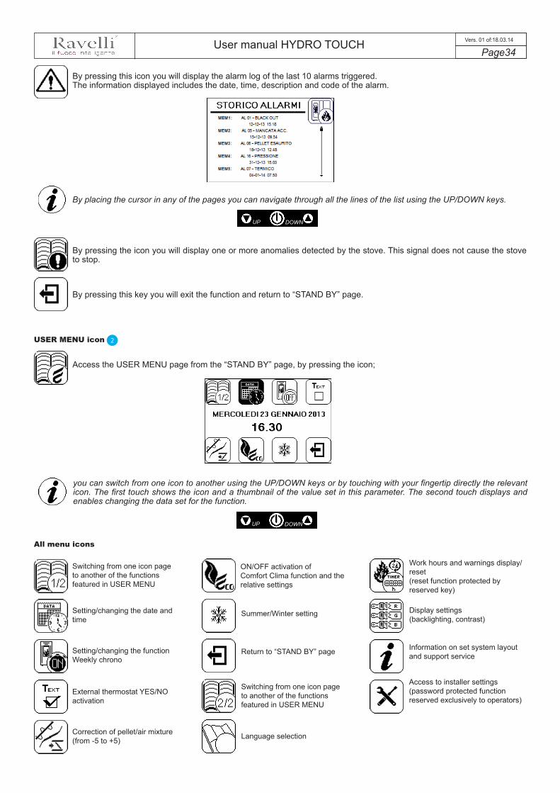
User manual HYDRO TOUCH Page34
Vers. 01 of:18.03.14
By pressing this icon you will display the alarm log of the last 10 alarms triggered. The information displayed includes the date, time, description and code of the alarm.
By pressing the icon you will display one or more anomalies detected by the stove. This signal does not cause the stove to stop.
By pressing this key you will exit the function and return to “STAND BY” page.
By placing the cursor in any of the pages you can navigate through all the lines of the list using the UP/DOWN keys.
USER MENU icon
Access the USER MENU page from the “STAND BY” page, by pressing the icon;
2
you can switch from one icon to another using the UP/DOWN keys or by touching with your fingertip directly the relevant icon. The first touch shows the icon and a thumbnail of the value set in this parameter. The second touch displays and enables changing the data set for the function.
UP DOWN
UP DOWN
All menu icons
Switching from one icon page to another of the functions featured in USER MENU
Setting/changing the date and time
Setting/changing the function Weekly chrono
External thermostat YES/NO activation
Correction of pellet/air mixture (from -5 to +5)
ON/OFF activation of Comfort Clima function and the relative settings
Summer/Winter setting
Return to “STAND BY” page
Switching from one icon page to another of the functions featured in USER MENU
Language selection
Work hours and warnings display/reset (reset function protected by reserved key)
Display settings (backlighting, contrast)
Information on set system layout and support service
Access to installer settings (password protected function reserved exclusively to operators)

User manual HYDRO TOUCH Page35
Vers. 01 of:18.03.14
Other functions available in USER MENU
With the chronothermostat function, it is possible to program the automatic switching on and off of the stove based on set time slots.
Upon the first pressure of the icon, you will display a thumbnail; a second pressure provides access to weekly Chrono setting/change function.
By pressing the icon you will activate/deactivate the Chrono function (ON indicates that the Chrono function is active).
By pressing the icon you will be able to switch to the next Chrono setup page.
The two keys enable sliding the cursor to set the desired time; time indication on the display varies according to the position of the cursor; black olours indicates the selected times activated for operation.
The example in the picture above shows that Monday the stove will operate according to the following schedule:switch on at 6.00 a.m. - switch off at 9.00 a.m.switch on at 11.00 a.m. - switch off at 1.00 p.m.switch on at 6.00 p.m. - switch off at 10.00 p.m.
To switch to the next day, use the two UP and DOWN selection keys of the control panel.
The key allows you to copy the settings of the selected day.
The key allows you to reset the settings of the selected day.
Chronothermostat
THUMBNAIL FUNCTION
The key enables/disables the stove for the time slots selected.
UP DOWN

User manual HYDRO TOUCH Page36
Vers. 01 of:18.03.14
By pressing the icon you will cancel all settings shown in the setup menu.The display shows the following confirmation page:
The key enables pasting the copied setting in the next day or during the following days.
The key enables resetting th setting in the memory, thus saving a new daily setting.
The example in the picture shows that the Chrono function has been copied from Monday to Friday and has the same switch on and off schedule.
Choose "YES" if you want to reset all previous settings, otherwise select "NO" using the two selection buttons.
Press the key to confirm the selection.
Press the key after completing the settings/changes to exit the function.
USING THIS METHOD, IT IS NECESSARY TO VERIFY THAT AFTER EACH AUTOMATIC SHUTDOWN THE GRATE IS ALWAYS VERY CLEAN TO GUARANTEE CORRECT AUTOMATIC SWITCH ON. AUTOMATIC SWITCH ON.
External thermostat YES/NO activation
The presence of an external thermostat enables immediate control of the temperature desired for the house. Before activating it, make sure you have connected the external thermostat to the special contacts located on the back of the stove, identified by the writing T.EXT.
Upon the first pressure of the icon, you will display a thumbnail; a second pressure provides access to external thermostat YES/NO activation.
FUNCTIONTHUMBNAIL

User manual HYDRO TOUCH Page37
Vers. 01 of:18.03.14
The two keys enable modifying the value; by choosing YES, the external thermostat operation is enabled; by choosing NO, the thermostat is disabled.
Press the key to confirm the selection.
Press the key after completing the settings/changes to exit the function.
With the external thermostat enabled, the icon will be displayed ticked, as shown in the figure.
NOTE: the symbol , alternated with the symbol , indicates the presence of the thermostat.
TON is displayed when there is a heating request (contact close);TOFF is displayed when the desired room temperature is reached (contact open);When the stove reaches the set temperature (TOFF), the ambient modulation is enabled.
For the electrical connection of the external thermostat please refer to the chapter dedicated to wiring of the various parts controlled by the stove.
Correction of air/pellet mixture (from -5 to +5)
Setting of the AIR-PELLET mix enables immediate variation in the quantity of air inbound of the stove and the quantity of pellets loaded on the grate. The stove is tested and inspected with DIN PLUS certified pellets. If using another type of pellets or uncertified pellets, fuel may need adjustment. Normally, variation is implemented on the “% FLOW” to regulate the air inbound and therefore combustion; if the flow regulation is not sufficient, it may be necessary to also vary the “% PELLETS“ feeding rate.
Upon the first pressure of the icon, you will display a thumbnail; a second pressure provides access to pellet/air correction function (both standard settings are 0).
By pressing the icon you will display/modify the useful air settings to improve combustion.
The two keys enable modifying the amount of pellets from minimum -5 to maximum +5.
Press the key to confirm the selection.
Modify the value that varies from minimum -5 to maximum +5 using the keys as shown above.
THUMBNAIL FUNCTION
CONNECT AN EXTERNAL THERMOSTAT WITH A SIMPLE DRY CONTACT, THEREFORE, NOT POWERED. MOREOVER, WE RECOMMEND YOU USE A THERMOSTAT WITH A MINIMUM OFFSET OF 3°C IF YOU INTEND TO USE THE COMFORT CLIMA FUNCTION.

User manual HYDRO TOUCH Page38
Vers. 01 of:18.03.14
Press the key after completing the settings/changes to exit the function.
NOTE: The number indicated during the change of parameters refers only to a percentage value that acts on the default parameters set on the electronic board (exclusively in the WORK phase). These values should be changed in the event of poor combustion, due in many cases to the purchase of pellets differing from those used during stove testing.
Summer/Winter settingSummer/Winter setting should be used exclusively to control advanced layouts in the presence of a hot domestic water storage circuit (boiler). In the standard hydraulic circuit, the SUMMER setting is not active.
Upon the first pressure of the icon, you will display a thumbnail; a second pressure provides access to Summer/Winter season setting function.
The two keys enable varying the Summer/Winter setting.
Press the key to confirm the selection.
Press the key after completing the settings/changes to exit the function.
Language selection
This function enables selecting the language of the display among the currently available languages: Italian, French, English, German, Spanish, Danish and Flemish.
Upon the first pressure of the icon, you will display a thumbnail; a second pressure provides access to the page that enables you to change the language.
The two keys enable you to select the desired language.
Press the key to confirm the selection.
Press the key after completing the settings/changes to exit the function.
THUMBNAIL FUNCTION
THUMBNAIL FUNCTION
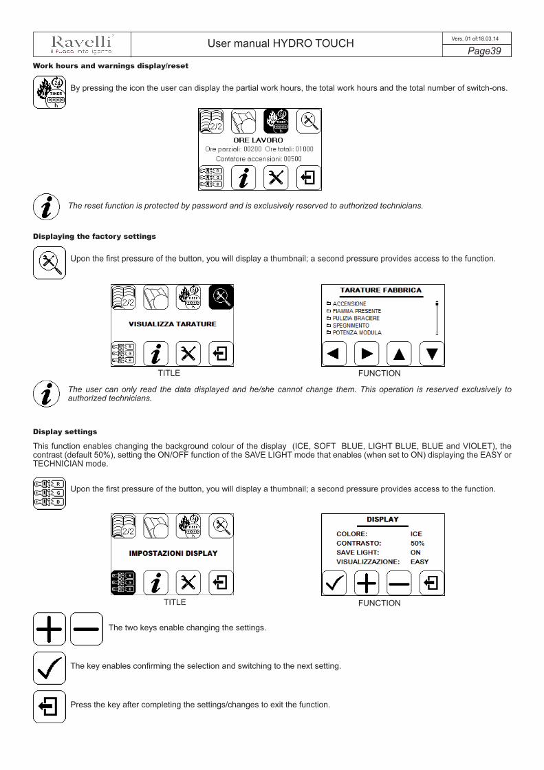
User manual HYDRO TOUCH Page39
Vers. 01 of:18.03.14
Work hours and warnings display/reset
By pressing the icon the user can display the partial work hours, the total work hours and the total number of switch-ons.
The reset function is protected by password and is exclusively reserved to authorized technicians.
Displaying the factory settings
Upon the first pressure of the button, you will display a thumbnail; a second pressure provides access to the function.
The user can only read the data displayed and he/she cannot change them. This operation is reserved exclusively to authorized technicians.
Display settings
This function enables changing the background colour of the display (ICE, SOFT BLUE, LIGHT BLUE, BLUE and VIOLET), the contrast (default 50%), setting the ON/OFF function of the SAVE LIGHT mode that enables (when set to ON) displaying the EASY or TECHNICIAN mode.
Upon the first pressure of the button, you will display a thumbnail; a second pressure provides access to the function.
The two keys enable changing the settings.
The key enables confirming the selection and switching to the next setting.
Press the key after completing the settings/changes to exit the function.
TITLE FUNCTION
TITLE FUNCTION
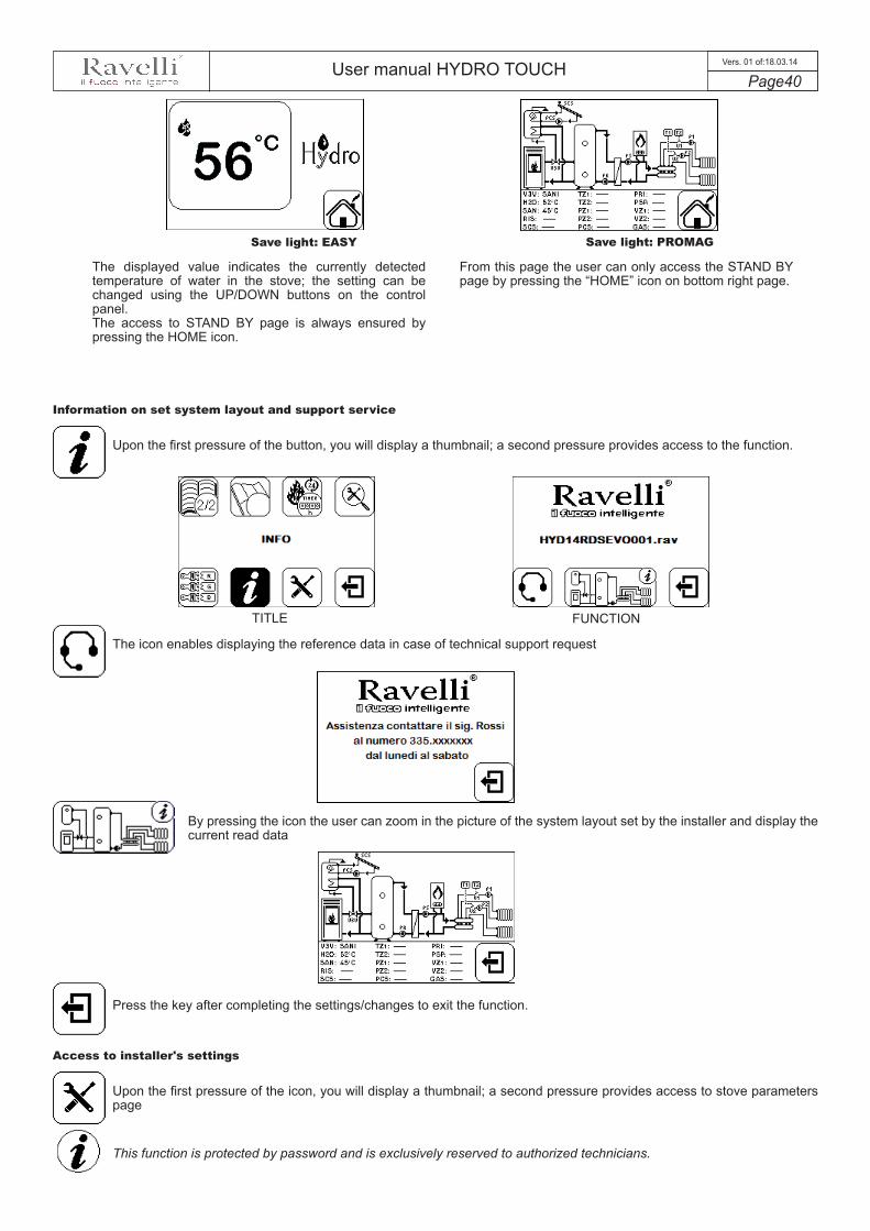
User manual HYDRO TOUCH Page40
Vers. 01 of:18.03.14
Save light: EASY Save light: PROMAG
The displayed value indicates the currently detected temperature of water in the stove; the setting can be changed using the UP/DOWN buttons on the control panel. The access to STAND BY page is always ensured by pressing the HOME icon.
From this page the user can only access the STAND BY page by pressing the “HOME” icon on bottom right page.
Information on set system layout and support service
Upon the first pressure of the button, you will display a thumbnail; a second pressure provides access to the function.
The icon enables displaying the reference data in case of technical support request
By pressing the icon the user can zoom in the picture of the system layout set by the installer and display the current read data
Press the key after completing the settings/changes to exit the function.
Access to installer's settings
Upon the first pressure of the icon, you will display a thumbnail; a second pressure provides access to stove parameters page
This function is protected by password and is exclusively reserved to authorized technicians.
TITLE FUNCTION
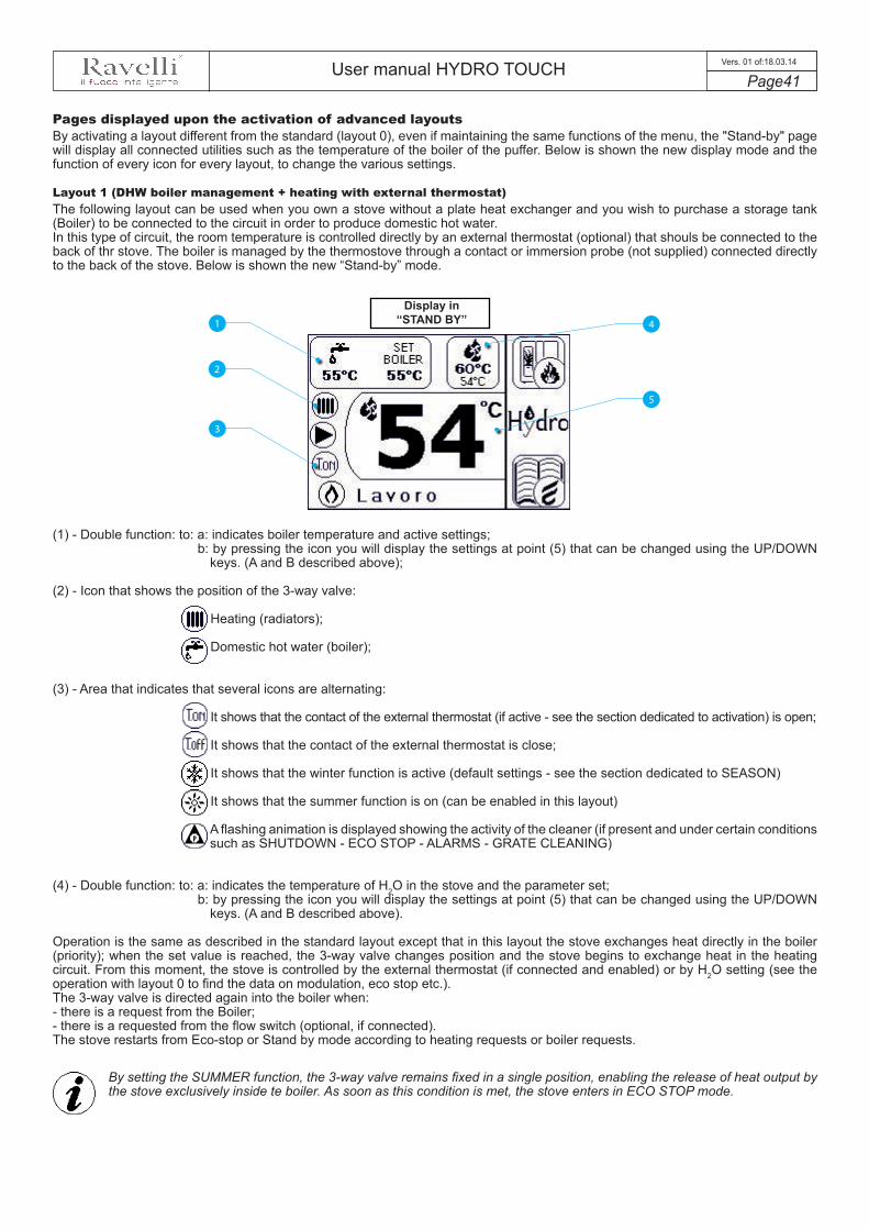
User manual HYDRO TOUCH Page41
Vers. 01 of:18.03.14
Pages displayed upon the activation of advanced layoutsBy activating a layout different from the standard (layout 0), even if maintaining the same functions of the menu, the "Stand-by" page will display all connected utilities such as the temperature of the boiler of the puffer. Below is shown the new display mode and the function of every icon for every layout, to change the various settings.
Layout 1 (DHW boiler management + heating with external thermostat) The following layout can be used when you own a stove without a plate heat exchanger and you wish to purchase a storage tank (Boiler) to be connected to the circuit in order to produce domestic hot water.In this type of circuit, the room temperature is controlled directly by an external thermostat (optional) that shouls be connected to the back of thr stove. The boiler is managed by the thermostove through a contact or immersion probe (not supplied) connected directly to the back of the stove. Below is shown the new “Stand-by” mode.
2
3
1
5
4
(1) - Double function: to: a: indicates boiler temperature and active settings;b: by pressing the icon you will display the settings at point (5) that can be changed using the UP/DOWN
keys. (A and B described above);
(2) - Icon that shows the position of the 3-way valve:
Heating (radiators);
Domestic hot water (boiler);
(3) - Area that indicates that several icons are alternating:
It shows that the contact of the external thermostat (if active - see the section dedicated to activation) is open;
It shows that the contact of the external thermostat is close;
It shows that the winter function is active (default settings - see the section dedicated to SEASON)
It shows that the summer function is on (can be enabled in this layout)
A flashing animation is displayed showing the activity of the cleaner (if present and under certain conditions such as SHUTDOWN - ECO STOP - ALARMS - GRATE CLEANING)
(4) - Double function: to: a: indicates the temperature of H2O in the stove and the parameter set;b: by pressing the icon you will display the settings at point (5) that can be changed using the UP/DOWN
keys. (A and B described above).
Operation is the same as described in the standard layout except that in this layout the stove exchanges heat directly in the boiler (priority); when the set value is reached, the 3-way valve changes position and the stove begins to exchange heat in the heating circuit. From this moment, the stove is controlled by the external thermostat (if connected and enabled) or by H2O setting (see the operation with layout 0 to find the data on modulation, eco stop etc.). The 3-way valve is directed again into the boiler when:- there is a request from the Boiler;- there is a requested from the flow switch (optional, if connected).The stove restarts from Eco-stop or Stand by mode according to heating requests or boiler requests.
Display in “STAND BY”
By setting the SUMMER function, the 3-way valve remains fixed in a single position, enabling the release of heat output by the stove exclusively inside te boiler. As soon as this condition is met, the stove enters in ECO STOP mode.

User manual HYDRO TOUCH Page42
Vers. 01 of:18.03.14
Layout 2 (storage puffer management)
In this type of circuit, the storage puffer is managed by the stove due to a contact or immersion probe (optional) connected to the back of the stove. By connecting the external thermostats to the expansion board (optional), the user can control a recirculation pump or pick-up pumps active on 2 areas. Below is shown the new “Stand-by” mode.
2
3
1
5
4
(1) - Double function: to: a: indicates puffer temperature and active settings;b: by pressing the icon you will display the settings at point (5) that can be changed using the UP/DOWN
keys. (A and B described above);
(2) - Icon that shows the position of the 3-way valve:
Heating (storage puffer);
(3) - Area that indicates that several icons are alternating:
It shows that the contact of the external thermostat (if active - see the section dedicated to activation) is open;
It shows that the contact of the external thermostat is close;
It shows that the winter function is active (default settings - see the section dedicated to SEASON)
It shows that the summer function is on (cannot be controlled for this type of system)
A flashing animation is displayed showing the activity of the cleaner (if present and under certain conditions such as SHUTDOWN - ECO STOP - ALARMS - GRATE CLEANING)
(4) - It shows stove H2O temperature and the maximum value (read-only) that can be reached by the water.
The operation is the same as for the standad layout, except for the fact that in this layout the stove exchanges heat directly in the storage puffer; when it reaches the set temperature, the stove switches to ECO STOP mode and then restarts if the temperature drops below a restart value (set by the installer upon testing).
Display in “STAND BY”
With regard to layouts 2 or 3, the “Save-Light” page shows the temperature and the settings of the storage puffer
The temperature displayed shows the current value measured by the storage puffer; the settings can be changed using the keys A and B. Switch on and switch off is controlled by PROLONGED PRESSURE of middle key C.
BA
C
Display in “SAVE LIGHT”

User manual HYDRO TOUCH Page43
Vers. 01 of:18.03.14
Layout 3 (DHW boiler + storage puffer management)
The following layout combines the functions of the previous layouts and is recommended to stoves provided with a storage puffer without internal coil preset for domestic hot water.In this type of circuit the boiler is managed by the thermostove through a contact or immersion probe (not supplied) connected directly to the back of the stove. The same applies to the control of the storage puffer that is provided by the thermostove through a contact or immersion probe (not supplied) connected directly to the back of the stove. By connecting the external thermostats to the expansion board (optional), the user can control a recirculation pump or pick-up pumps active on 2 areas. Below is shown the new “Stand-by” mode.
2
3
1
6
4
(1) - Double function: to: a: indicates puffer temperature and active settings;b: by pressing the icon you will display the settings at point (6) that can be changed using the UP/DOWN
keys. (A and B described above);
(2) - Icon that shows the position of the 3-way valve:
Heating (storage puffer);
Domestic hot water (boiler);
(3) - Area that indicates that several icons are alternating:
It shows that the contact of the external thermostat (if active - see the section dedicated to activation) is open;
It shows that the contact of the external thermostat is close;
It shows that the winter function is active (default settings - see the section dedicated to SEASON)
It shows that the summer function is on (can be enabled in this layout)
A flashing animation is displayed showing the activity of the cleaner (if present and under certain conditions such as SHUTDOWN - ECO STOP - ALARMS - GRATE CLEANING)
(4) - Double function: to: a: indicates boiler temperature and active settings;b: by pressing the icon you will display the settings at point (6) that can be changed using the UP/DOWN
keys. (A and B described above);
(5) - It shows stove H2O temperature and the maximum value (read-only) that can be reached by the water.
The operation is the same as described in the standard layout except that in this layout the stove exchanges heat directly in the boiler (priority); when the set value is reached, the 3-way valve changes position and the stove begins to exchange heat in the storage puffer. When the set temperature is reached, the stove enters in ECO STOP mode; it restarts if the temperature drops below the restart value (set by the installer upon testing).The 3-way valve is directed again into the boiler when:- there is a request from the Boiler;- there is a requested from the flow switch (optional, if connected).The stove restarts from Eco-stop or Stand by mode according to storage puffer requests or boiler requests.
Display in “STAND BY”
5
By setting the SUMMER function, the 3-way valve remains fixed in a single position, enabling the release of heat output by the stove exclusively inside te boiler. As soon as this condition is met, the stove enters in ECO STOP mode.
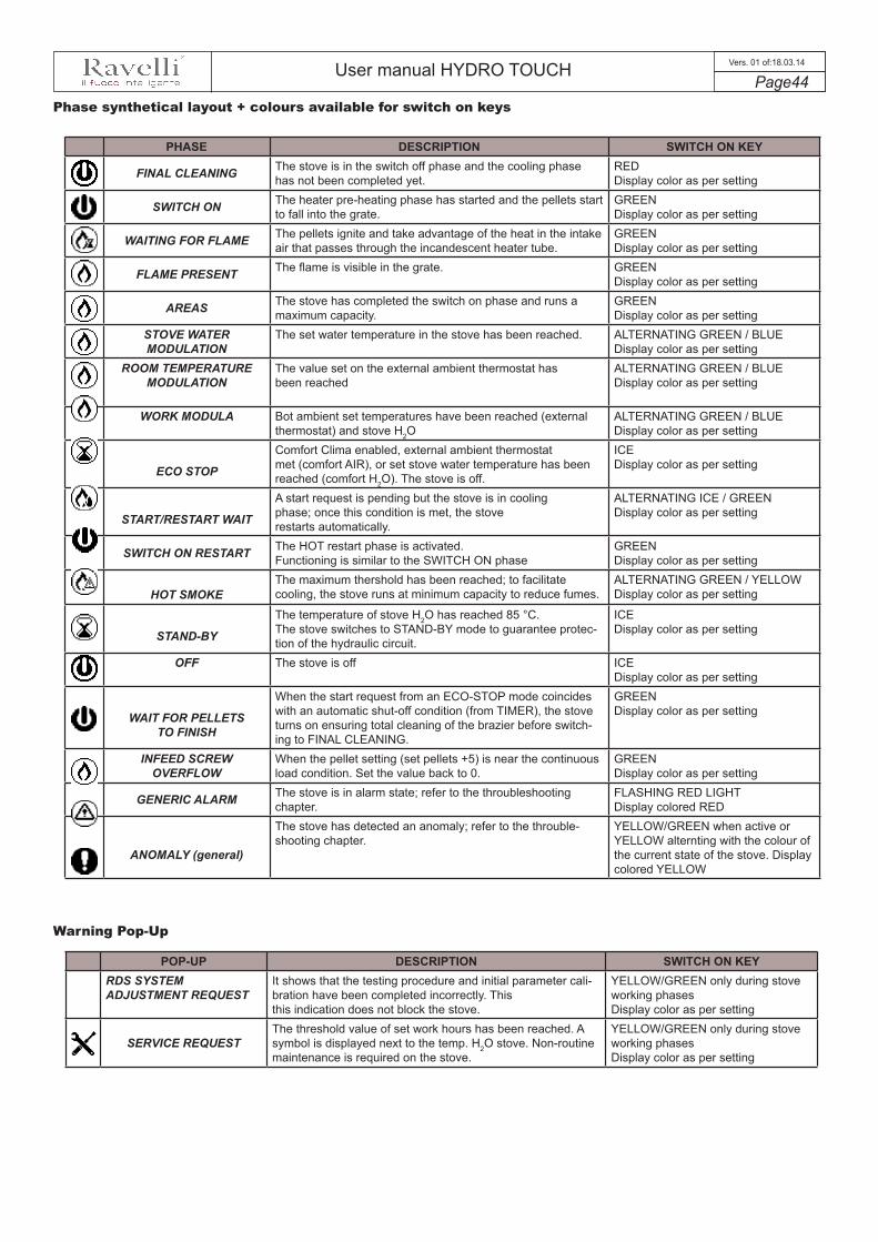
User manual HYDRO TOUCH Page44
Vers. 01 of:18.03.14
Phase synthetical layout + colours available for switch on keys
PHASE DESCRIPTION SWITCH ON KEY
FINAL CLEANING The stove is in the switch off phase and the cooling phase has not been completed yet.
REDDisplay color as per setting
SWITCH ON The heater pre-heating phase has started and the pellets start to fall into the grate.
GREENDisplay color as per setting
WAITING FOR FLAME The pellets ignite and take advantage of the heat in the intake air that passes through the incandescent heater tube.
GREEN Display color as per setting
FLAME PRESENT The flame is visible in the grate. GREENDisplay color as per setting
AREAS The stove has completed the switch on phase and runs a maximum capacity.
GREENDisplay color as per setting
STOVE WATER MODULATION
The set water temperature in the stove has been reached. ALTERNATING GREEN / BLUEDisplay color as per setting
ROOM TEMPERATURE MODULATION
The value set on the external ambient thermostat has been reached
ALTERNATING GREEN / BLUEDisplay color as per setting
WORK MODULA Bot ambient set temperatures have been reached (external thermostat) and stove H2O
ALTERNATING GREEN / BLUEDisplay color as per setting
ECO STOP
Comfort Clima enabled, external ambient thermostat met (comfort AIR), or set stove water temperature has been reached (comfort H2O). The stove is off.
ICEDisplay color as per setting
START/RESTART WAIT
A start request is pending but the stove is in cooling phase; once this condition is met, the stove restarts automatically.
ALTERNATING ICE / GREENDisplay color as per setting
SWITCH ON RESTART The HOT restart phase is activated. Functioning is similar to the SWITCH ON phase
GREENDisplay color as per setting
HOT SMOKEThe maximum thershold has been reached; to facilitatecooling, the stove runs at minimum capacity to reduce fumes.
ALTERNATING GREEN / YELLOWDisplay color as per setting
STAND-BY
The temperature of stove H2O has reached 85 °C. The stove switches to STAND-BY mode to guarantee protec-tion of the hydraulic circuit.
ICEDisplay color as per setting
OFF The stove is off ICEDisplay color as per setting
WAIT FOR PELLETS TO FINISH
When the start request from an ECO-STOP mode coincides with an automatic shut-off condition (from TIMER), the stove turns on ensuring total cleaning of the brazier before switch-ing to FINAL CLEANING.
GREENDisplay color as per setting
INFEED SCREW OVERFLOW
When the pellet setting (set pellets +5) is near the continuous load condition. Set the value back to 0.
GREENDisplay color as per setting
GENERIC ALARM The stove is in alarm state; refer to the throubleshooting chapter.
FLASHING RED LIGHTDisplay colored RED
ANOMALY (general)
The stove has detected an anomaly; refer to the throuble-shooting chapter.
YELLOW/GREEN when active or YELLOW alternting with the colour of the current state of the stove. Display colored YELLOW
Warning Pop-Up
POP-UP DESCRIPTION SWITCH ON KEYRDS SYSTEM ADJUSTMENT REQUEST
It shows that the testing procedure and initial parameter cali-bration have been completed incorrectly. This this indication does not block the stove.
YELLOW/GREEN only during stove working phasesDisplay color as per setting
SERVICE REQUESTThe threshold value of set work hours has been reached. A symbol is displayed next to the temp. H2O stove. Non-routine maintenance is required on the stove.
YELLOW/GREEN only during stove working phasesDisplay color as per setting
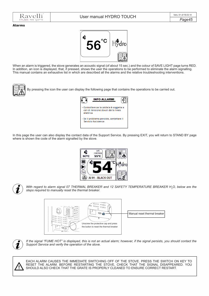
User manual HYDRO TOUCH Page45
Vers. 01 of:18.03.14
Alarms
By pressing the icon the user can display the following page that contains the operations to be carried out.
With regard to alarm signal 07 THERMAL BREAKER and 12 SAFETY TEMPERATURE BREAKER H2O, below are the steps required to manually reset the thermal breaker.
When an alarm is triggered, the stove generates an acoustic signal (of about 15 sec.) and the colour of SAVE LIGHT page turns RED. In addition, an icon is displayed, that, if pressed, shows the user the operations to be performed to eliminate the alarm signalling.This manual contains an exhaustive list in which are described all the alarms and the relative troubleshooting interventions.
In this page the user can also display the contact data of the Support Service. By pressing EXIT, you will return to STAND BY page where is shown the code of the alarm signalled by the stove.
Unscrew the protective cap and press the button to reset the thermal breaker
Manual reset thermal breaker
If the signal “FUME HOT” is displayed, this is not an actual alarm; however, if the signal persists, you should contact the Support Service and verify the operation of the stove.
EACH ALARM CAUSES THE IMMEDIATE SWITCHING OFF OF THE STOVE. PRESS THE SWITCH ON KEY TO RESET THE ALARM. BEFORE RESTARTING THE STOVE, CHECK THAT THE SIGNAL DISAPPEARED. YOU SHOULD ALSO CHECK THAT THE GRATE IS PROPERLY CLEANED TO ENSURE CORRECT RESTART.
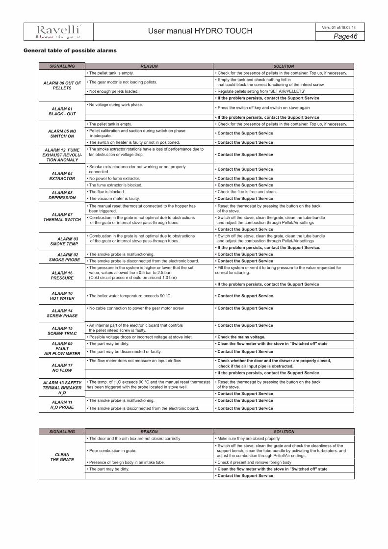
User manual HYDRO TOUCH Page46
Vers. 01 of:18.03.14
SIGNALLING
ALARM 06 OUT OF PELLETS
ALARM 01BLACK - OUT
ALARM 05 NO SWITCH ON
ALARM 12 FUME EXHAUST REVOLU-
TION ANOMALY
ALARM 04 EXTRACTOR
ALARM 08 DEPRESSION
ALARM 07 THERMAL SWITCH
ALARM 03 SMOKE TEMP.
ALARM 02 SMOKE PROBE
ALARM 16 PRESSURE
ALARM 10 HOT WATER
ALARM 14SCREW PHASE
ALARM 15SCREW TRIAC
ALARM 09FAULT
AIR FLOW METER
ALARM 17NO FLOW
ALARM 13 SAFETY TERMAL BREAKER
H2O
ALARM 11H2O PROBE
REASON SOLUTION• The pellet tank is empty. • Check for the presence of pellets in the container. Top up, if necessary.
• The gear motor is not loading pellets. • Empty the tank and check nothing fell inthat could block the correct functioning of the infeed screw.
• Not enough pellets loaded. • Regulate pellets setting from “SET AIR/PELLETS”• If the problem persists, contact the Support Service
• No voltage during work phase.• Press the switch off key and switch on stove again
• If the problem persists, contact the Support Service• The pellet tank is empty. • Check for the presence of pellets in the container. Top up, if necessary.• Pellet calibration and suction during switch on phase
inadequate. • Contact the Support Service
• The switch on heater is faulty or not in positioned. • Contact the Support Service• The smoke extractor rotations have a loss of perfoemance due tofan obstruction or voltage drop. • Contact the Support Service
• Smoke extractor encoder not working or not properly connected. • Contact the Support Service
• No power to fume extractor. • Contact the Support Service• The fume extractor is blocked. • Contact the Support Service• The flue is blocked. • Check the flue is free and clean.• The vacuum meter is faulty. • Contact the Support Service
• The manual reset thermostat connected to the hopper hasbeen triggered.
• Reset the thermostat by pressing the button on the backof the stove.
• Combustion in the grate is not optimal due to obstructions of the grate or internal stove pass-through tubes.
• Switch off the stove, clean the grate, clean the tube bundle and adjust the combustion through Pellet/Air settings
• Contact the Support Service• Combustion in the grate is not optimal due to obstructions
of the grate or internal stove pass-through tubes.• Switch off the stove, clean the grate, clean the tube bundle and adjust the combustion through Pellet/Air settings
• If the problem persists, contact the Support Service.• The smoke probe is malfunctioning. • Contact the Support Service• The smoke probe is disconnected from the electronic board. • Contact the Support Service• The pressure in the system is higher or lower that the setvalue; values allowed from 0.5 bar to 2.5 bar.(Cold circuit pressure should be around 1.0 bar)
• Fill the system or vent it to bring pressure to the value requested for correct functioning.
• If the problem persists, contact the Support Service
• The boiler water temperature exceeds 90 °C. • Contact the Support Service.
• No cable connection to power the gear motor screw • Contact the Support Service
• An internal part of the electronic board that controls the pellet infeed screw is faulty.
• Contact the Support Service
• Possible voltage drops or incorrect voltage at stove inlet. • Check the mains voltage.• The part may be dirty. • Clean the flow meter with the stove in "Switched off" state
• The part may be disconnected or faulty. • Contact the Support Service
• The flow meter does not measure an input air flow • Check whether the door and the drawer are properly closed,check if the air input pipe is obstructed.
• If the problem persists, contact the Support Service
• The temp. of H2O exceeds 90 °C and the manual reset thermostat has been triggered with the probe located in stove well.
• Reset the thermostat by pressing the button on the backof the stove.
• Contact the Support Service• The smoke probe is malfunctioning. • Contact the Support Service
• The smoke probe is disconnected from the electronic board. • Contact the Support Service
REASON SOLUTION• The door and the ash box are not closed correctly • Make sure they are closed properly.
• Poor combustion in grate.• Switch off the stove, clean the grate and check the cleanliness of the support bench, clean the tube bundle by activating the turbolators. and adjust the combustion through Pellet/Air settings.
• Presence of foreign body in air intake tube. • Check if present and remove foreign body • The part may be dirty. • Clean the flow meter with the stove in "Switched off" state
• Contact the Support Service
SIGNALLING
CLEAN THE GRATE
General table of possible alarms

User manual HYDRO TOUCH Page47
Vers. 01 of:18.03.14
Anomalies
When the stove detects an anomaly, it emits a long acoustic signal (about 15 sec.), and the color of SAVE LIGHT page turns YEL-LOW without interrupting the operation of the stove. Access the STAND BY page by pressing the key “HOME”; you will see a new icon that, once pressed, enables you to display the type of anomaly encountered by the stove.
The pressure of the icon gives you access to the classic "STOVE STATE" page, and within that, by pressing the icon once again, you will display the page that shows any anomalies detected by the stove. Below is given an example.
The signal of an anomaly does not compromise the operation of the stove that, as previously said, continues to work. As soon as the anomaly is reset, the page restores the default colour and the icon described above disappears.
General alarm table
REASON SOLUTION
Flow meter faulty, the RDS system is not working • Contact the Support Service
Expansion board that controls the Solar, Tank, Zone 1 and Zone 2 does not communicate with the mother board • Contact the Support Service
The pellet level sensor has detected that there are o pellets in the tank (if the optional pellet tank is provided) • Load pellets into the optional tank
Expansion board that controls the Zone 1, Zone 2, Zone 3 and Zone 4 does not communicate with the mother board • Contact the Support Service
Probe that controls the temperature in the boiler does not read the data• Check whether the cable that conveys the signal to the mother board is disconnected
• Contactthe Support Service
Probe that controls the temperature in the puffer does not read the data• Check whether the cable that conveys the signal to the mother board is disconnected
• Contactthe Support Service
Probe that controls the temperature in the optional puffer, that should be installed in the lower part, does not read the data
• Check whether the cable that conveys the signal to the mother board is disconnected
• Contactthe Support Service
Probe that controls the temperature in the Solar collector does not read the data
• Check whether the cable that conveys the signal to the mother board is disconnected
• Contactthe Support Service
SIGNALLING
01 - 09 flow meter
02 - Expansion 1 offline
03 - Pellet silo empty
04 - Expansion 2 offline
05 - Boiler probe faulty
06 - Puffer probe faulty
07 - LO Puffer probe faulty
08 - Solar collector probe faulty

User manual HYDRO TOUCH Page48
Vers. 01 of:18.03.14
Before any cleaning operation on the stove, implement the following precautions:
- switch off the stove and disconnect the power cord with the stove in "Switched OFF" state;- make sure all the parts of the stove are cold;- make sure the ash is completely cooled.
To clean the surfaces of the coated metal parts, use a cloth soaked in water or water and soap. Attention! Use of abrasive detergents or diluents can damage the surface of the stove.
All stoves made by Ravelli (except for version EVO 14) are equipped with automatic cleaner that displaces any ash deposits from the combustion chamber inside the grate, that does not require their removal as it only releases the bottom of the grate dedicated to primary air intake. Therefore, it is required to make sure the grate is properly cleaned to ensure optimal combustion at all times and avoid possible overheating that could change the color of the paint or cause the door coating layer to peel off. Furthermore, poor cleaning of the grate can cause stove switch on problems.
To remove the grate, unthread the pins that lock the grate to its support; now remove the grate and make sure there is no dirt inside it.
If you use another type of pellets, even of the same brand, this may lead to differences in combustion that may result in greater ash deposits inside the grate. Correct cleaning, carried out on a daily basis, allows the stove to burn pellets omptimally with a good and steady heating output, preventing malfunctions that over time may call for the intervention of a technician to restore stove's operation.
Remove the drawer from the stove and remove the ash collected using an ash vacuum; be very careful if the grate is still hot as this can damage the cleaning equipment.
Clean basket
Basket that needs cleaning
Cleaning operations of the stove depend on the quality of the pellets used and the frequency of use. It may be necessary to carry out these operations on a daily basis.
PLEASE READ CAREFULLY THE FOLLOWING INSTRUCTIONS TO PERFORM PROPER CLEANING. FAILURE TO COMPLY WITH THESE INSTRUCTIONS MAY LEAD TO MALFUNCTIONS OF THE STOVE.
Grate
Drawer ash
Cleaning should be provided by the user
Clean the surfaces
Grate cleaning should be carried out before each switch on
Cleaning the ash pan
Ash pan that needs to be emptied
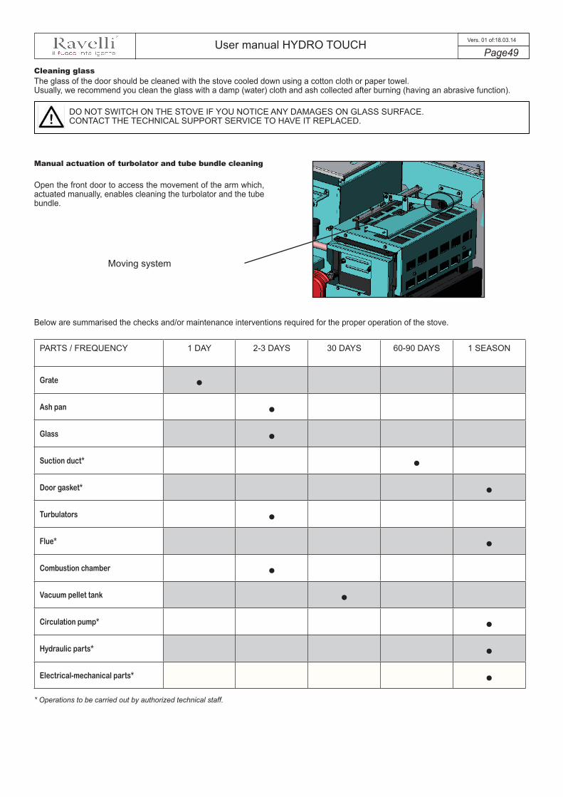
User manual HYDRO TOUCH Page49
Vers. 01 of:18.03.14
The glass of the door should be cleaned with the stove cooled down using a cotton cloth or paper towel. Usually, we recommend you clean the glass with a damp (water) cloth and ash collected after burning (having an abrasive function).
DO NOT SWITCH ON THE STOVE IF YOU NOTICE ANY DAMAGES ON GLASS SURFACE. CONTACT THE TECHNICAL SUPPORT SERVICE TO HAVE IT REPLACED.
Open the front door to access the movement of the arm which, actuated manually, enables cleaning the turbolator and the tube bundle.
Cleaning glass
Manual actuation of turbolator and tube bundle cleaning
Moving system
PARTS / FREQUENCY 1 DAY 2-3 DAYS 30 DAYS 60-90 DAYS 1 SEASON
Grate •Ash pan •Glass •Suction duct* •Door gasket* •Turbulators •Flue* •Combustion chamber •Vacuum pellet tank •Circulation pump* •Hydraulic parts* •Electrical-mechanical parts* •
Below are summarised the checks and/or maintenance interventions required for the proper operation of the stove.
* Operations to be carried out by authorized technical staff.

User manual HYDRO TOUCH Page50
Vers. 01 of:18.03.14
Accessories The stoves of touch line made by Ravelli feature a set of hydraulic parts that control all the layouts of the system described in the section "Examples of hydraulic installation". Below are listed all the accessories available.
Wall-mounted thermostat: It enables activating the heating sytem when there as temeperature increase request installed in the home. The systems operates both manually and by means of a specific programmable ambient thermostat. Compared to a regular thermostat, this thermostat displays the state of Ravelli stove, signalling any anomay or alarm.
Electronic expansion board: It enables a more complex management of home system; the system allows the management of 2 areas with the relative recirculation pumps or zone valves, it controls the palet level sensors (when the optional TANK is present), and also controls the solar function (from the following firmware versions).
Puffer Lately, in the management of heating systems the pellet stove is combined with a storage tank (that acts as a (that acts as a heat reserve). This, thanks to the stratification of the hot water inside it, enables withdrawing water at different temperatures according to the type of heating available; for example wall-mounted radiators or radiant panels (floor panels) that need a withdrawal temperature below 35/40 ° C. It is also recommended because it allows the coexistence of several heat sources such as solar panels, heat pumps or back-up gas boilers. There are different types of storage tanks, from simple versions to “pipe in tank” with one or several coils or dedicated coil DHW (domestic hot water).
cylinderIt behaves exactly like a puffer as regards the storage and the stratification of water, with the difference that the boiler is used exclusively for the production of hot domestic water. There are various types of boilers in terms of size and use, there is also the possibility to integrate a solar panel for domestic water management in the summer season, bypassing the use of the pellet boiler.
Three-way valveThis electromechanical component controlled by Ravelli electronic equipment, can be used to manage advanced systems that require the use of a bolier combined with the Ravelli stove or a combined boiler + puffer system; it has the purpose of directing the heat output by the stove to heat the entire househeating system, having always available domestic hot water or water for heating both storage tanks.
Mixing valve: The mixing valve enables the adjustment of a centralized heating system by mixing the water that comes out from the stove with the water returning from the system to obtain the desired temperature for the utility delivery water (management of radiant systems with delivery temperature below 35/40°C). This valve is also used for hot domestic water request at the temperature desired by the user; in this case, the hot domestic water coming out from the DHW line is mixed with water at lower temperature supplied by the water mains of the house.
Anti-condensation valve: The temperature rise valve, more commonly known as condensation valve is a special mixing valve with thermostatic control that optimizes the connection of the pellet heat generator to the storage tank or the heating system, automatically adjusting the temperature of the water returning to the genrator, temperature that is set with thermostats chosen according to your specific requirements. It has the task of preventin water from returing into the stove at very low temperares that may create condensate.
3-way motorized
3-way with spring return
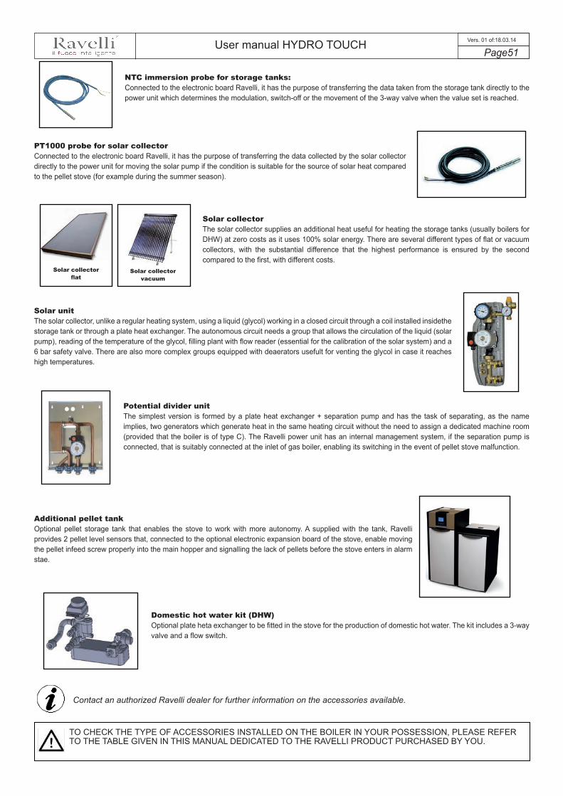
User manual HYDRO TOUCH Page51
Vers. 01 of:18.03.14
NTC immersion probe for storage tanks: Connected to the electronic board Ravelli, it has the purpose of transferring the data taken from the storage tank directly to the power unit which determines the modulation, switch-off or the movement of the 3-way valve when the value set is reached.
PT1000 probe for solar collector Connected to the electronic board Ravelli, it has the purpose of transferring the data collected by the solar collector directly to the power unit for moving the solar pump if the condition is suitable for the source of solar heat compared to the pellet stove (for example during the summer season).
Solar collector The solar collector supplies an additional heat useful for heating the storage tanks (usually boilers for DHW) at zero costs as it uses 100% solar energy. There are several different types of flat or vacuum collectors, with the substantial difference that the highest performance is ensured by the second compared to the first, with different costs.
Solar unit The solar collector, unlike a regular heating system, using a liquid (glycol) working in a closed circuit through a coil installed insidethe storage tank or through a plate heat exchanger. The autonomous circuit needs a group that allows the circulation of the liquid (solar pump), reading of the temperature of the glycol, filling plant with flow reader (essential for the calibration of the solar system) and a 6 bar safety valve. There are also more complex groups equipped with deaerators usefult for venting the glycol in case it reaches high temperatures.
Potential divider unit The simplest version is formed by a plate heat exchanger + separation pump and has the task of separating, as the name implies, two generators which generate heat in the same heating circuit without the need to assign a dedicated machine room (provided that the boiler is of type C). The Ravelli power unit has an internal management system, if the separation pump is connected, that is suitably connected at the inlet of gas boiler, enabling its switching in the event of pellet stove malfunction.
Additional pellet tank Optional pellet storage tank that enables the stove to work with more autonomy. A supplied with the tank, Ravelli provides 2 pellet level sensors that, connected to the optional electronic expansion board of the stove, enable moving the pellet infeed screw properly into the main hopper and signalling the lack of pellets before the stove enters in alarm stae.
Domestic hot water kit (DHW) Optional plate heta exchanger to be fitted in the stove for the production of domestic hot water. The kit includes a 3-way valve and a flow switch.
Contact an authorized Ravelli dealer for further information on the accessories available.
TO CHECK THE TYPE OF ACCESSORIES INSTALLED ON THE BOILER IN YOUR POSSESSION, PLEASE REFER TO THE TABLE GIVEN IN THIS MANUAL DEDICATED TO THE RAVELLI PRODUCT PURCHASED BY YOU.
Solar collector flat
Solar collector vacuum

User manual HYDRO TOUCH Page52
Vers. 01 of:18.03.14
T1
T2
T3 T4 T5
V1 V2
V3
C1R1
G2
G1
G3
G8
G9
G6
S6
G4
G5
S1
S2
S3
S4
S5
S7
G7
LEGEND:Safety T1 - Pellet safetyT2 - Stove H2O safetyT3 - Vacuum switchT4/5 - Optional contactMotorsM1 - Fume extractorM2 - Infeed screw gear motor M3 - Mechanical cleanerSpring valvesV1 - Pellet-gas valveV2 - Heating valveV3 - DHW valveN.B.: V2 and V3 can be controlledwith a single 3-way valveCirculatorsC1 - Stove circulatorC2 - Potential divider circulatorResistanceR1 - 250watt heater
ProbesS1 - Stove probe 1S2 - Stove probe 2S3 - Fume probeS4 - Puffer 1 probeS5 - Puffer 2 probeS6 - Ext. Clima probe (optional)S7 - Boiler probeGeneralG1 - Modulating pump controller (not controlled in this application)
G2 - Extractor revolution reading encoderG3 - Flow meterG4 - Mechanical cleaner contactG5 - Flow switchG6 - Pressure transducerG7 - External thermostatG8 - Graphic panel contactG9 - BUS communication contact
C2
Mother board wiring diagram
G8 - Graphic panel contact
G9 - Contact BUS communication (optional external thermostat Ravelli)
blackredwhite
M1
M2 M3
Ac
1A
c2
Ac
3A
c4
Ac
5N
Ac1
Ac2
Ac3
N
Ac4
Ac5
INFE
ED S
CR
EW S
AFET
Y BR
EAKE
R
230
VAC
PO
WER
SU
PPLY
UN
IT
RC
FIL
TER
GAS BOILER ENABL.

User manual HYDRO TOUCH Page53
Vers. 01 of:18.03.14
Primary expansion wiring diagram
V4
V5
M4
P4
G9
G9
P3
G12G13
G7aS8
S9
P1P2
LEGEND:
MotorsM4 - Optional silo loaderCirculatorsC3 - Modular solar circulatorC4 - Solar circulatorC5 - Zone 1 circulation or recirculation pumpC6 - Zone 2 circulation pump
GeneralG7a - Zone 1 external thermostatG7b - Zone 2 external thermostatG9 - BUS communication contactG12 - Operating mode (open circuit = zones + solar; close circuit = zones only)G13 - valves/Circulation pumps (open circuit = zones with valves; close circuit = circulation pump zones only)
G7b
ProbesS8 -Lambda probe (not managed in this model)S9 - Solar collector probe (PT1000)SensorsP1 - Stove tank pellet level sensorP2 - Optional pellet Tank level sensorSpring valvesV4 - Zone 1 valve (daytime)V5 - Zone 2 valve (nighttime)
T1 - Pellet safetyT2 - Stove H2O safety
T3 - Vacuum switch
T4/5 - Optional contactG4 - Mechanical cleaner contact
M1 - Fume extractor
M2 - Infeed screw gear motor 3 rpm EVO 14 4.75 rpm EVO 18 5.2 rpm EVO 24
M3 - Mechanical cleaner2 rpm only for models EVO18 and 24
M4 - Optional silo loader4,75 rpm for all models
V1 - Pellet-gas spring valveV2 - Heating spring valveV3 - DHW spring valveV4 - Zone 1 valve (daytime)V5 - Zone 2 valve (nighttime)
V2/V3 - 3-way valve heating / DHW
C1 - Stove circulator
C2 - Potential divider circulatorC3/ - Modular solar circulatorC4 - Solar circulatorC5 - Zone 1 circulation or recirculation
pumpC6 - Zone 2 circulation pump
S3 - Fume probe
S1 - Stove 1 probe (NTC 10k) S2 - Stove 2 probe (NTC 10k) S6 - Ext. Clima probe (optional)
(NTC 10k)
S4 - Puffer 1 probe (NTC 10k) S5 - Puffer 2 probe (NTC 10k) S7 - Boiler probe (NTC 10k)S9 - Solar collector probe (PT1000)
G6 - Pressure transducer
R1 - 250watt heaterG5 - Flow switch
G7 - External thermostatG7a - Zone 1 external thermostatG7b - Zone 2 external thermostat
P1 - Pellet level sensor (stove tank)P2 - Pellet level sensor (optional tank)
G12 and G13<--- close contact open contact --->
C6
C5
C4
C3
230 VAC POWER SUPPLY UNIT
User manual HYDRO TOUCH Page54
Vers. 01 of:18.03.14
Warranty conditions
The warranty covers manufacturing material defects, provided the product was not subject to breakages caused by improper use, negligence, incorrect connection, tampering or installation errors.Not covered by the warranty:- vermiculite (firex 600)- the door glass;- the fibre seals;- the paint;- the combustion basket in stainless steel or cast iron;- the resistor;- the coloured majolica;- any damage due to inadequate installation and/or tampering with the stove and/or negligence on the customer's part.Use of poor quality pellets or any other material which could damage the components of the stove cause the warranty to become invalid,as well as the relevant liability of the manufacturer.Therefore, we recommend you use pellets that meet the requirements in the specific chapter.All damages caused by transport are not recognised, therefore we recommend you carefully check the goods on receipt, immediatelyadvising the dealer of any damage.The warranty form must be detached and sent within 8 days of purchase to the following address:
AICO S.p.A.Via Kupfer, 31
25036 Palazzolo s/O Brescia (ITALIA)
Info and problems
For any information or support request, please contact the local dealer or support centre as they are authorized to provide solutions to all requests and intervene directly, when necessary.
Warranty
Warranty Certificate
AICO S.p.A. would like to thank you for agreeing to buy one of our pellet stoves and invites you, the customer, to:- read the instructions for installation, use and maintenance of the stove.- note the warranty conditions reported below.
The warranty form annexed must be compiled and stamped by the installer to activate the warranty. Otherwise, the warranty of the product shall not be effective.

DATE INTERVENTION CARRIED OUT
MAINTENANCE

AICO S.p.A.Via Kupfer, 31 - 25036 Palazzolo sull’Oglio / BS - ITALYTel. +39.030.7402939Fax +39.030.7301758Internet : www.ravelligroup.itE-mail: [email protected]
AICO S.p.A. is not liable for any errors in this booklet and is free to make changes to the features of its products without prior warning.