user manual pv analyzer z100 - solar pv test equipment and
TRANSCRIPT

010102_EN
User Manual PV Analyzer Z100
User Manual PV Analyzer Z100 2
Content 1. Nomenclature ....................................................................................................................................... 3
1.1 Warning signs............................................................................................................................... 3 1.2 Tips and recommendations .......................................................................................................... 3
2. Limited warranty and limitation of warranty ......................................................................................... 4 2.1 Warranty disclaimer ..................................................................................................................... 5
3. Unpacking and commissioning .............................................................................................................. 6 3.1 Scope of delivery .......................................................................................................................... 6 3.2 Commissioning ............................................................................................................................. 7
4. Safety ................................................................................................................................................... 8 5. Introduction.......................................................................................................................................... 9 6. Operation ........................................................................................................................................... 11
6.1 Startup ....................................................................................................................................... 11 6.2 Wifi setup and Z100 Wifi basics .................................................................................................. 11 6.3 Instrument self-check ................................................................................................................. 13 6.4 Measurements ........................................................................................................................... 14
7. Maintenance and service .................................................................................................................... 31 8. Labelling on instrument ...................................................................................................................... 32 9. Storage and disposal ........................................................................................................................... 33
9.1 Storage ...................................................................................................................................... 33 9.2 Disposal ..................................................................................................................................... 33
10. Technical data..................................................................................................................................... 34 10.1 Z100 Features ............................................................................................................................ 34 10.2 Measurement specifications ...................................................................................................... 34 10.3 General Instrument specifications .............................................................................................. 37

User Manual PV Analyzer Z100 3
1. Nomenclature
1.1 Warning signs
Please note that the manual uses the following safety instructions. The safety instructions should be followed carefully. Failure to do so may cause personal injury or irreparable damage to the equipment.
WARNING Personal injury / death. A situation of use of a technical nature or the like which may cause injury or death.
CAUTION Damage to the machine or accessory. A situation of use of a technical nature or the like, which can cause damage to the machine or accessories.
NOTICE Important information. A situation of use of a technical nature or the like, which is very important.
1.2 Tips and recommendations
INFORMATION Provides useful tips and recommendations and provides information on how to use the product efficiently and without interruptions.

User Manual PV Analyzer Z100 4
2. Limited warranty and limitation of warranty Each EmaZys product is warranted to be free from defects in material and workmanship under normal use and service. The warranty period is one year and begins on the date of shipment. Parts, product repairs, and services are warranted for 90 days. This warranty extends only to the original buyer or end-user customer of a EmaZys authorized reseller, and does not apply to fuses, disposable batteries, or to any product which, in EmaZys's opinion, has been misused, altered, neglected, contaminated, or damaged by accident or abnormal conditions of operation or handling. EmaZys warrants that software will operate substantially in accordance with its functional specifications for 90 days and that it has been properly tested by EmaZys. EmaZys does not warrant that software will be 100% error free or operate without interruption. EmaZys authorized resellers shall extend this warranty on new and unused products to end-user customers only but have no authority to extend a greater or different warranty on behalf of EmaZys. Warranty support is available only if product is purchased through an EmaZys authorized sales outlet or Buyer has paid the applicable international price. EmaZys reserves the right to invoice Buyer for importation costs of repair/replacement parts when product purchased in one country is submitted for repair in another country. EmaZys's warranty obligation is limited, at EmaZys's option, to refund of the purchase price, free of charge repair or replacement of a defective product which is returned to an EmaZys authorized service center within the warranty period. To obtain warranty service, contact EmaZys on E-mail [email protected] to obtain return authorization information, then send the product to the service center, with a description of the difficulty, postage and insurance prepaid (FOB Destination). EmaZys assumes no risk for damage in transit. Following warranty repair, the product will be returned to Buyer, transportation prepaid (FOB Destination). If EmaZys determines that failure was caused by neglect, misuse, contamination, alteration, accident, or abnormal condition of operation or handling, including overvoltage failures caused by use outside the product’s specified rating, or normal wear and tear of mechanical components, EmaZys will provide an estimate of repair costs and obtain authorization before commencing the work. Following repair, the product will be returned to the Buyer transportation prepaid and the Buyer will be billed for the repair and return transportation charges (FOB Shipping Point). THIS WARRANTY IS BUYER'S SOLE AND EXCLUSIVE REMEDY AND IS IN LIEU OF ALL OTHER WARRANTIES, EXPRESS OR IMPLIED, INCLUDING BUT NOT LIMITED TO ANY IMPLIED WARRANTY OF MERCHANTABILITY OR FITNESS FOR A PARTICULAR PURPOSE. EMAZYS SHALL NOT BE LIABLE FOR ANY SPECIAL, INDIRECT, INCIDENTAL, OR CONSEQUENTIAL DAMAGES OR LOSSES, INCLUDING LOSS OF DATA, ARISING FROM ANY CAUSE OR THEORY.

User Manual PV Analyzer Z100 5
Since some countries or states do not allow limitation of the term of an implied warranty, or exclusion or limitation of incidental or consequential damages, the limitations and exclusions of this warranty may not apply to every buyer. If any provision of this Warranty is held invalid or unenforceable by a court or other decision-maker of competent jurisdiction such holding will not affect the validity or enforceability of any other provision.
EmaZys ApS
Kochsgade 31 DK- 5000 Odense E-mail [email protected]
2.1 Warranty disclaimer
PV Analyzer Z100 is warranted for 12 months from the reception. The warranty does not cover the battery. There is no warranty on the device, if you use other cables than the supplied. The warranty will be invalid if the product is damaged due to any of the following: • Neglect to follow the User Manual • Use of the product for purposes for which it was not intended • Natural wear • Incorrect fitting • Mechanical or technical alterations • Use of unauthorised spare parts
User Manual PV Analyzer Z100 6
3. Unpacking and commissioning
3.1 Scope of delivery
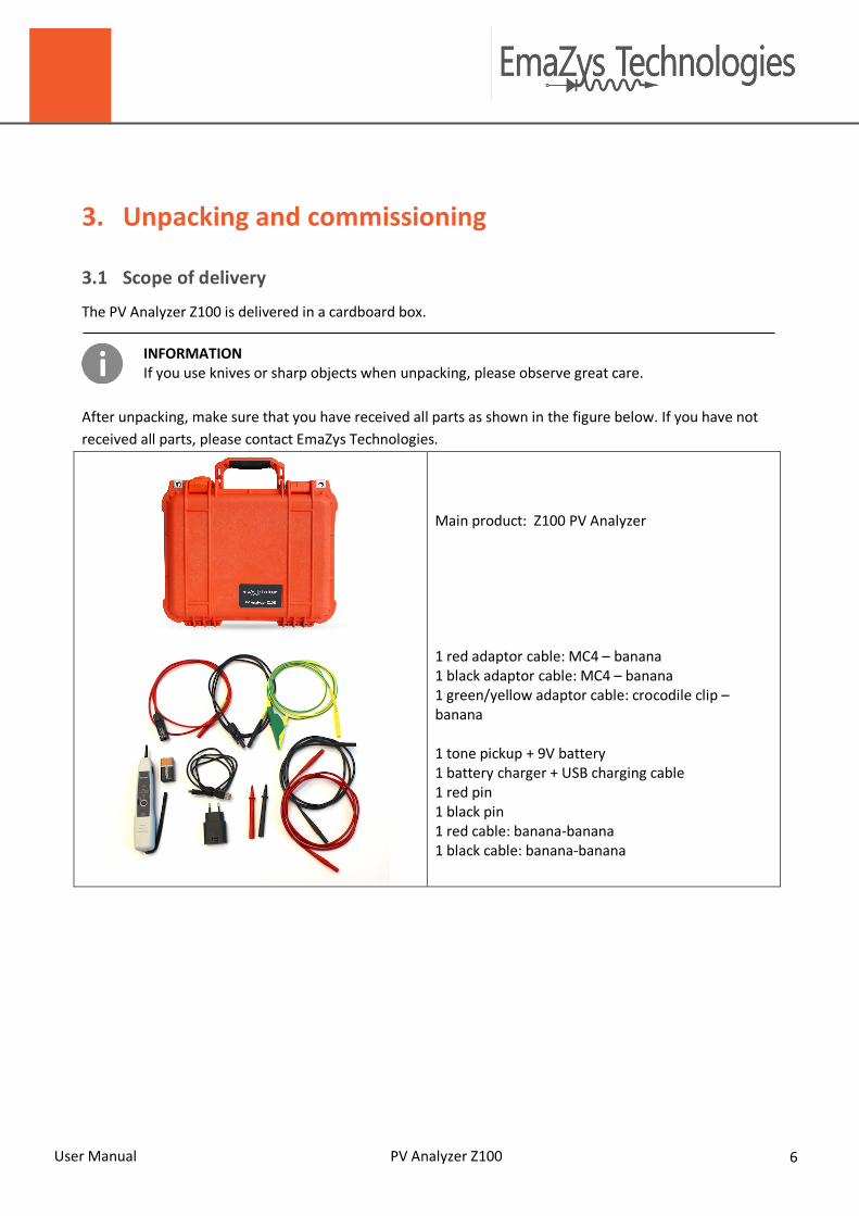
The PV Analyzer Z100 is delivered in a cardboard box.
INFORMATION If you use knives or sharp objects when unpacking, please observe great care.
After unpacking, make sure that you have received all parts as shown in the figure below. If you have not received all parts, please contact EmaZys Technologies.
Main product: Z100 PV Analyzer 1 red adaptor cable: MC4 – banana 1 black adaptor cable: MC4 – banana 1 green/yellow adaptor cable: crocodile clip –banana 1 tone pickup + 9V battery 1 battery charger + USB charging cable 1 red pin 1 black pin 1 red cable: banana-banana 1 black cable: banana-banana

User Manual PV Analyzer Z100 7
3.2 Commissioning
3.2.1 Instrument battery Prior to start-up please check that the battery is fully charged. The battery can be charged with any standard smartphone charger with a USB output or via a computer USB port. You can also order a 230V charger from EmaZys Technologies.
3.2.2 Control interface In order for the instrument to be operated by one person, the control interface is separated from the main instrument and thus can be brought along while the operator e.g. walks from module to module blocking the sun-light from reaching the modules one in a turn. The control interface can be any smart device with WiFi transceiver and a Chrome browser (other browser may also work, but the software is optimized for use with Chrome browser) All measurement functionality by Z100 is accessed and controlled via the WEB interface on your smart device generated by the Z100.
3.2.3 Cables Connect the supplied cables to the instrument. The red wire is connected to the Red (+) connection socket, the black wire is connected to the Black (-) connection socket and the yellow/green wire is connected to GND.
WARNING Personal injury / death. Make sure cables used to connect the instrument to photovoltaic modules and strings are CAT III, 1000V compliant.
CAUTION Damage to the machine or accessory. It is not recommended to use cables other than the supplied. The instrument's warranty is no longer valid if other types of cables are used,

User Manual PV Analyzer Z100 8
4. Safety Before carrying out measurements with PV Analyzer Z100, you must ensure that:
• there is sufficient space to operate the instrument • the necessary tools are present on the site • the operator has a general knowledge of PV modules (photovoltaic modules) and is trained to work
in high voltage environments • the instrument is correctly connected • the instrument and the measurement cables are in good condition. Check that the cables are not
cracked or damaged in any way.
NOTICE Important information. • The PV Analyzer Z100 and the User Manual are intended for use by adequately trained
personnel. • Before use, the operator must have read the user manual. • The User manual must be kept near the instrument.
WARNING Personal injury / death PV module measurements are performed in high voltage areas. Always use approved safety equipment designed for high voltage installations. If subjected to an electrical shock, you MUST seek medical advice, even if you feel well. Some potentially harmful effects may not occur until several hours after exposure!
CAUTION Damage to the machine or accessory. • Exercise caution in use. • The PV Analyzer Z100 should be used wherever possible in a dry environment. • The instrument's lid should always be closed during long-term measurements. Make sure to
mark up the measuring site.

User Manual PV Analyzer Z100 9
5. Introduction The PV Analyzer Z100 is a portable and battery powered instrument used to detect and localize faults in strings of series connected photovoltaic modules. Specifically, the instrument has the following features and applications:
1) Ground faults testing i.e. RISO, location of singular ground faults, with programmable timer for extended ground fault testing
2) Photovoltaic module string impedance curve, for system health assessment 3) Open circuit voltage measurement 4) Disconnects in photovoltaic module strings e.g. in cables, connectors or bus-bars 5) Damaged bypass diodes, both short-circuited and open-circuited bypass diodes 6) Data can be saved and stored directly as PDF files for reporting and documentation
The instrument is connected to the string terminals e.g. at the string inverter or combiner box and also to the ground reference for the PV installation.
Make sure to connect the inputs correctly on the Z100. (Cables are all coloured accordingly).
Once connected and activated, it will perform impedance spectroscopy between any two of the three connected terminals as well as measure the terminal voltages and currents flowing under various DC loads induced by the instrument. By combining the results from these various measurements using the on-board computer, critical faults in the system can be localized. All measurement functionality by Z100 is accessed and controlled via the smart device connected to the WiFi address of the Z100. On the Z100 itself, the only controls are an ON/OFF button (on the externally mounted battery) as well as a button used to wake the Z100 up premature during a timer session.
User Manual PV Analyzer Z100 10
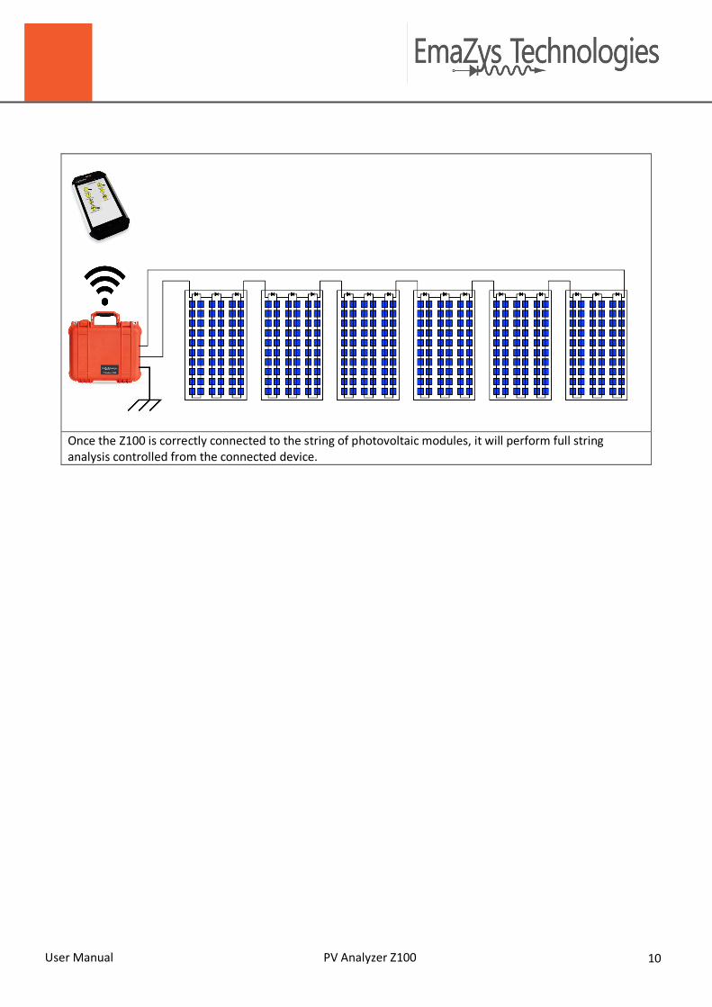
Once the Z100 is correctly connected to the string of photovoltaic modules, it will perform full string analysis controlled from the connected device.
User Manual PV Analyzer Z100 11
6. Operation
6.1 Startup
Turn on the instrument by pressing the ON/OFF button on the battery to the right.
The green LED on the battery will light up instantly, and the LEDs on the front panel of the Z100 will light up after initial boot-up (about 30 seconds). Green LED signals that power is on. The yellow LED signals that WiFi antenna is active (you may also notice a blue blinking LED in the wifi adapter on the front panel).
6.2 Wifi setup and Z100 Wifi basics
The connection device for operating the Z100 must be a device with a Google Chrome browser. You will communicate with the Z100 through the browser window at all times.
1) After powering up the Z100, wait for the green and yellow LED´s to indicate that Z100 WiFi is active, the computer inside the Z100 box will set up a Wifi hotspot (local wireless network) that can be connected with other Wifi devices, so make sure that Wifi on your preferred smart device (smartphone, tablet or laptop) is also enabled.
2) The name of the hotspot access point will be in the form: ‘Z100-xxxx-xxxx’, where the x´s represent a unique number for every Z100. Once you have found the Z100 hotspot simply connect using the password: ‘Xoplag10’.
3) Once connected with the Z100, open your Chrome browser and type ‘z100/’ in the URL bar. If you are already connected to the internet by other means, you have to type ‘192.168.4.1.’ instead, as this signifies to your device not to look up the Z100 through a DNS server, but only find it within the local WiFi network itself.
4) When using a new browser to access the Z100 for the first time, it might be necessary to
enable PopUps for the Z100 homepage, in order to allow it to store pdf reports from your subsequent measurements. This is done within Chrome by clicking on the “No PopUp” icon, that appears to the right of the URL-address bar AFTER creating the first pdf report (It is only needed the first time you generate a report).
5) Optional: With Chrome it is possible to make a shortcut to the Z100 homepage, so you
can open up directly to the Z100 with an icon of it’s own from your device. Go to the Z100 homepage, and open the menu to the right of the URL address bar and tap on “Add to home Screen”
Please contact EmaZys Technologies if there is a problem connecting to the Z100.

User Manual PV Analyzer Z100 12
INFORMATION Please note:
A) If the Z100 has been disconnected or turned off, you need to reconnect to the Z100 hotspot.
B) If you get out of reach of the Z100, it may also be necessary to reconnect your device with the Z100, dependent on the availability of other nearby networks within reach of your device.
C) Remember to shut down after use e.g. disconnect battery or turn off battery.
This is how your main menu should look like, when viewed within your browser window.
A. Main menu User Interface. This screen will
appear in your Chrome browser window when connected with the Z100 Wifi hotspot. Note: The IP address shown is NOT representative
B. You can always return to the Main menu
from e.g. VOC measurement. The main icon will take you back to Main from anywhere in the WEB interface of the Z100 You can also use the back button on a phone to go back one level.
B
A

User Manual PV Analyzer Z100 13
C. Help button is shown with a question mark “?” in the upper right corner. Use this throughout to obtain supportive information about the current menu/measurement.
6.3 Instrument self-check
During power up of the instrument, the instrument will conduct a thorough self-check and possible errors will be listed in the ‘Settings’ menu. The Z100 also conducts self-check procedures of internal HW components that are critical to the safety of the operator. Self-check procedures are carried out as part of all measurement features and on all involved critical HW components. Failures detected could be temporary (excessive voltages, excessive currents or overheating during measurements) or permanent (e.g. malfunction of a HW component). In both cases, a pop-up window will appear to instruct the operator on how to proceed if a failure occurs. Most often a power off/on cycle will be sufficient to fully analyse and in most cases also clear temporary errors.
C

User Manual PV Analyzer Z100 14
6.4 Measurements
Some rudimentary control and assessment of the sun-light reaching the string and individual PV modules is necessary. I.e. in order to accurately detect and localize ground faults, and disconnects in cables and connectors, all the modules in the string under test need to be illuminated by at least 100 W/m2. The most accurate results are obtained when the irradiation level is steady throughout your measurement. This is also the case if you want to estimate the overall string series resistance Rs. When checking the health state of module bypass diodes it is also necessary with an ambient sunlight intensity at each module of at least 100 W/m2. Please note that testing the health state of the diodes in a specific PV module in the string, requires blocking the sunlight from reaching that module. If Rp of the string or a subset of the string down to individual cells or modules needs to be measured the sunlight needs again to be blocked from reaching the PV cells or modules being tested, however this can be achieved by measuring at nighttime (I.e. Rp of the entire string).

User Manual PV Analyzer Z100 15
6.4.1 Change Settings
Before starting the actual measurements, it is advised to enter information about the site you are working on. This information will be transferred to the pdf reports to assist you in documenting your findings. The information can be entered under ‘Change settings’.
A. Select "Settings" in the main menu.
B. Type in your company name, name of
technician and site/location. For each measurement report, you have the choice of adding additional information that might be helpful in the subsequent analysis of your results.
C. When the entry is complete, just press
"Save". The entered data is then included in the reports made from the various measurements.
B
C

User Manual PV Analyzer Z100 16
6.4.2 Ground Fault measurementFunctionality: This test is used to measure the isolation of the PV string towards ground. If poor isolation is found, the instrument will attempt to position the fault. Typical faults seen are due to water and moist intrusion in PV modules or connectors (replace faulty module/connectors) or in case of a damaged cable (replace cable segment).
In the above example, a leakage has been found between panel 8 and 10, with a Riso below 100Kohm, with 420V over the string.
A. Before starting the actual measurement, the number of PV modules should be selected using the ’+’ and ‘-’ keys.
B. After hitting the "measure"-button, the instrument will perform a ground isolation measurement. The measurement will take close to one minute to complete. Longer if e.g. ambient light conditions vary a lot.
C. In the ‘Results’ window the measured Riso together with the string open circuit voltage are returned. If Riso is less than 3 MOhm, the instrument will assume there is a singular point-like ground leakage and will estimate its position with reference to the positive terminal of the PV string. “Position" will indicate the number of modules counting from the positive string terminal towards the leakage point. If “Position” states a number between 0 and 1, the leakage point is likely to be in the cable segment going to the positive string terminal from the instrument. On the other hand, if the number is around the number of modules, the leakage point is likely in last module or the cable between the last module and the instrument. The text returned in ‘Conclusion’ will indicate a fault and state the position thereof if the leakage to ground is deemd critical (<1 MOhm) .
A
B
C

User Manual PV Analyzer Z100 17
NOTICE Important information.
• Due to the inherent uncertainty of the fault localization method and due to the possibility of multiple or distributed faults, it is highly recommended to verify a fault position by bypassing a given faulty module or cable segment with a known good cable and redo the measurement to ensure good isolation BEFORE repairing the string e.g. replacing a cable segment or PV module.
• It is good practice to verify correct connection of the string to the instrument AND
sufficient illumination of modules (>100 W/m2) by comparing the measured PV voltage with the expected voltage (Number of modules multiplied by the Voc of each module in the string).
• The measurement analysis assumes that modules in the string are producing evenly. If a
fault is not found accurately, it may point to additional or other problems and the user is advised to run a ‘String test’

User Manual PV Analyzer Z100 18
6.4.3 String TesterFunctionality: Using the ‘String tester’ is a good diagnostic tool to check overall health of the string. The spectrum is re-corded by the instrument by measuring the associated current running in the string when subjected to an alternating voltage stimulus spanning a frequency range within [100 Hz to 100 kHz]. The impedance – generally a complex number - at these various frequencies is the result of the voltage stimulus across the PV string divided by the measured current.
A. Connect the instrument to the PV string and
press the ‘Measure’ button to collect a spectrum. The measurement will take up to a minute to complete.
B. The phase angle of the impedance may be displayed using the toggle switch.
In the example shown to the right, Rs is 16.9 Ohm as is the low frequency norm at a voltage of close to 410V, which indicate a healthy string of 12 x 250W panels with a decent sun irradiation. With a higher irradiation Rs could go as low as 10 Ohm. Riso is also very good and measured to be over 40Mohm.
A

User Manual PV Analyzer Z100 19
6.4.4 Calculating the expected solar PV string series resistance RS
RS is the string series resistance that should ideally be very low in order to minimize power loss. It is the sum of junction diffusion loss in the PV cells and of all series losses in cables, connectors and bus-bars in the PV modules. An illuminated healthy PV string (with irradiation > 100 W/m2) will only have an impedance represented by RS, since the photo diode is fully turned ON by the PV current and thus effectively shorting Cd and RP. Below is a diagram of a simple so-called three parameter PV string model. It contains the three component parameters RP – the shunt resistance, RS – the series resistance and Cd – the diffusion capacitance. The remaining components in the model are the light current generator ILIGHT and shunt diode with current ID. The current source models the current delivered by the PV string when short-circuited and the diode characteristics determine the open circuit voltage of the string.
Solar module string - equivalent circuit. This model is roughly equivalent to the solar module string, and a basis for understanding the impedance measurement.
1) ILIGHT is the current generated by light on the modules 2) ID is the diode current 3) Cd is the diffusion capacitance 4) RP is the parallel (shunting) resistance 5) RS is the series resistance
RS should be estimated in the frequency range f = 100 Hz to f = 10 kHz where the simple model is most accurate (at higher frequencies e.g. effects of cable inductance become a factor and cause the impedance to increase). At EmaZys Technologies, a study on more than 500 commercial modules using different PV cell technology and size has been conducted and a worst-case relationship concerning the dependence of RS on ISC0 (short-circuit current at 1000 W/m2 irradiation) and VOC (open-circuit voltage) has been found:
𝑅" < 30Ω𝐴 ∗𝑉*+100𝑉 ∗
1000 𝑊𝑚/
𝐼𝑟𝑟 /𝐼3+4

User Manual PV Analyzer Z100 20
Example: Let’s see what this means by a concrete example. An operator is in the field conducting measurements on modules having ISC0 = 10A, string open circuit voltage is 500V and the irradiation has been measured at 100W/m2. The RS on a healthy string should be less than 150 Ohm according to the above formula. This estimate is generally applicable regardless of technology i.e. it applies to both crystalline and thin film technologies. However, there is significant variation between technologies. For instance, PV modules based on mc-Si cells typically has an RS value of half of the above estimate or less. Obviously, when there are many PV strings of similar construction in a test-site it is also possible to find potential outliers by comparison of measurement data. If RS is found to be too high, it is an indication of a problem e.g. with shading or bad cabling/connectors. If the impedance exceeds 10 kOhm at f = 100 Hz, there may be a disconnect in the string e.g. in the form of a bad internal junction, a broken cable or faulty connector. See info box below for tips on how to quickly locate the fault. RP is the string parallel (shunting) resistance that will be very high when the string is healthy (e.g. several KOhms per PV module). The effect of RP is only seen in strings that are partially or fully shaded or at nighttime. RP is estimated at low frequencies where the effect of Cd – the diffusion capacitance – is minimal.
6.4.5 Understanding “Low frequency norm” and “Low frequency Norm with load” We consider the electrical impedance of a system as an imaginary number:
Z = R+jX
Here R is the electrical resistance, j is the imaginary unit j= Ö-1 and X is the reactance. Reactance can be either capacitance or inductance. In case of solar PV modules, the impedance is highly dependent on the test signal frequency. When we represent the real part Re and an imaginary part Im in the complex plane (see figure below), we see that the impedance can be expressed as a vector Z with length:
|Z| = Ö(R2 +X2)
and phase angle
θ=arctan(X/R)
ThelengthoftheimpedancevectorisalsocalledtheNormoftheimpedance,anditisthenormoftheimpedancethatismeasuredbythestringtesterintheZ100.Zismeasuredinpracticalsituations,bysuperimposinganACvoltageVAC,whilemeasuringtheresultingACcurrentIAC:
Z=VAC/IAC

User Manual PV Analyzer Z100 21
Graphicalrepresentationofelectricalimpedance.WhenwerepresenttherealpartReandanimaginarypartIminthecomplexplane,weseethattheimpedancemayalsobeexpressedasavectorZwithlength|Z|andphaseangleθ.|Z|isalsoreferredtoattheimpedance“norm”.
TheZ100thetestsignalfrequencyisintheinterval100Hzto40kHz,andtheamplitudeisaround2V.Atlowfrequencies,wenormallydonotmeasureanynoteworthyreactanceXinilluminatedsolarPVmodules,andwethereforeseeonlytheseriesresistanceRSthestring
fà0=>X=0
|Z| = Ö(R2 +X2) => |Z|=ÖR2 = RThe“Lowfrequencynorm”willbeclosetotheRSvaluewhenthePVmodulesarefullyilluminated,andwhenthereisnoresistanceprobleminthestring.IfwemeasuresomethingverydifferentfromtheexpectedRSvalue,wethusdetectabnormalities.The“Lowfrequencynormwithload”shouldalsobelowwhenthesolarPVmodulesarefullyilluminated.TheloadmeansthatasmallcurrentisdrawnintheZ100instrument,meaningthatwemeasuretheimpedanceduringaflowofdirectcurrentDC.
Ifthe“Lowfrequencynorm”andthe“lowfrequencynormwithload”arebothhighvalues,itcouldmeanthate.g.acableisbroken.Ifthetwovaluesareverydifferente.g.ifthe“Lowfrequencynormwithload”islowcomparedtothe“lowfrequencynorm”theDCcurrentismakingthedifference.Thisimpliesthatsomefaultinternaltothecellsandmodulesispresenti.e.thebypassdiodesturnonandofferalowimpedancepathforthecurrent.

User Manual PV Analyzer Z100 22
6.4.6 Open Circuit VoltageFunctionality: This function simply measures the open Circuit Voltage of the string of photovoltaic modules.
Voltage is shown instantly. Just press main to go back to Main screen. In the example to the right almost 410V is measured across 12 x 250W mc Si modules indicating decent sun irradiation. If you see below 1V check for proper connection to the string, or check for a potential disconnect fault.

User Manual PV Analyzer Z100 23
6.4.7 Disconnect Functionality: This test is used to measure whether there is a disconnect in the PV string external to the modules. If a disconnect is found, the instrument will attempt to position the fault. Typical faults seen are due to broken cables or corrosion in connectors due to water intrusion, saline- or ammonia atmosphere (replace faulty connector). Series faults internal to PV modules are found using the ‘Bypass Diode Test’ function.
Continued on the following page!
A. The number of PV modules ‘N’ should be
selected using the ‘+’ and ‘-‘ keys.
B. Then the cable length to both the positive and the negative pole - measured in meters - has to be entered.
C. Finally the capacitance of the cables has to be estimated – if it’s dry weather then the cable capacitance typically will be around 80 pF/m. In the case that humidity in the ground is high, the cable capacitance can easily rise to around 120 pF/m.
Please note that cable capacitance per meter cables roughly equals 1/10 the capacitance of a single PV module and therefore the estimates of cabling lengths does not have to be extremely accurate. I.e. a faulty estimate of say 10 meters would probably only change the position by less than one PV modules.
A
B
C
User Manual PV Analyzer Z100 24
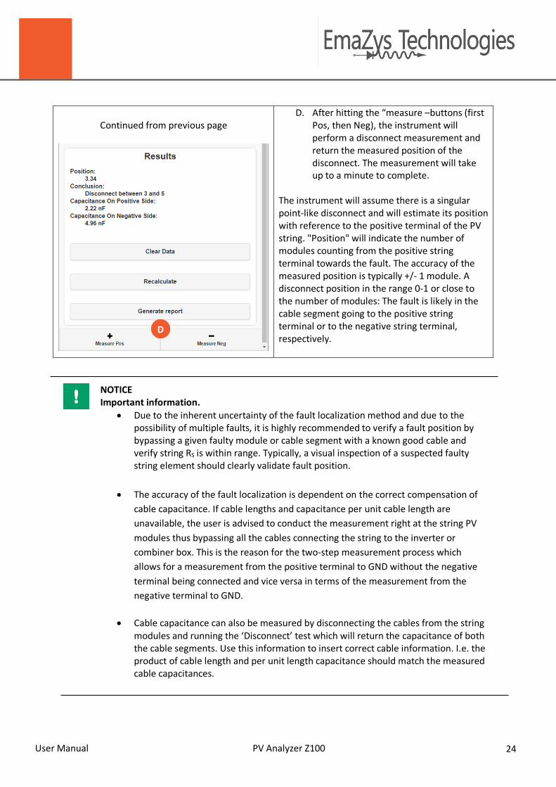
Continued from previous page
D. After hitting the “measure –buttons (first Pos, then Neg), the instrument will perform a disconnect measurement and return the measured position of the disconnect. The measurement will take up to a minute to complete.
The instrument will assume there is a singular point-like disconnect and will estimate its position with reference to the positive terminal of the PV string. "Position" will indicate the number of modules counting from the positive string terminal towards the fault. The accuracy of the measured position is typically +/- 1 module. A disconnect position in the range 0-1 or close to the number of modules: The fault is likely in the cable segment going to the positive string terminal or to the negative string terminal, respectively.
NOTICE Important information.
• Due to the inherent uncertainty of the fault localization method and due to the possibility of multiple faults, it is highly recommended to verify a fault position by bypassing a given faulty module or cable segment with a known good cable and verify string RS is within range. Typically, a visual inspection of a suspected faulty string element should clearly validate fault position.
• The accuracy of the fault localization is dependent on the correct compensation of
cable capacitance. If cable lengths and capacitance per unit cable length are unavailable, the user is advised to conduct the measurement right at the string PV modules thus bypassing all the cables connecting the string to the inverter or combiner box. This is the reason for the two-step measurement process which allows for a measurement from the positive terminal to GND without the negative terminal being connected and vice versa in terms of the measurement from the negative terminal to GND.
• Cable capacitance can also be measured by disconnecting the cables from the string modules and running the ‘Disconnect’ test which will return the capacitance of both the cable segments. Use this information to insert correct cable information. I.e. the product of cable length and per unit length capacitance should match the measured cable capacitances.
D

User Manual PV Analyzer Z100 25
6.4.8 Timer Functionality: This function is basically an automatic ground fault test. You can set a timer to perform the ground fault test and thus leave the instrument during testing. This can be an advantage if the ground fault is periodic e.g. if it only shows up in the early morning, but disappears after a few hours of sunlight.
A. The number of PV modules ‘N’ should be selected using the ‘+’ and ‘-‘ keys.
B. Select the duration of the test (I.e. 6 to 24 hrs). The Riso/GND fault measurement test will be conducted every 15 minutes for the entire duration of the test
C. ‘Schedule Timer’ will start the
measurement. The WiFi antenna will close down during test, and only the pressing of the yellow button on the front panel will wake up the WiFi signal from the Z100
A
B
C

User Manual PV Analyzer Z100 26
6.4.9 Module test Functionality: This test is used to check the functionality of the Bypass Diodes (BPD) in the junction box of the PV module and to find series faults internal to PV modules. Bypass diodes can fail e.g. as short circuited in the event of lightning strikes. When short-circuited, the string power production is reduced. They can also wear out over time and become open-circuited thus rendering their host module unprotected from e.g. hot spot formation and fast degradation in power production. The 3 measured parameters are:
1 - Module voltage estimation The module voltage drop caused by shading modules, one by one, is measured in the string of modules under test. Under normal circumstances, the string voltage drop thus corresponds closely to the voltage of the shaded module. The result of this testing procedure is an overview of the individual modules voltages in bar diagram form. Modules with a low voltage, relative to the majority of the string modules, may then be identified in a convenient manner. If a single module voltage is found to be about 2/3 or 1/3 of the normal open circuit module voltage, the problem could be caused by 1 or even 2 bypass diodes that are in a short circuit state. Short circuit bypass diodes are often seen as a damage following lightning strikes, but please note that many types of damage could lower the voltage of a solar PV module installed in the field.
2 - Impedance at open circuit condition
The low frequency impedance norm, measured in the open circuit state. In the case of fully illuminated modules, the low frequency impedance is normally very low; approximately around the RS value. A shaded module will however normally show a much raised impedance value, even when it is placed in a string showing a significant voltage. The high impedance appears, since the test signal must travel through the shaded solar cells in the module. The impedance is caused by a phenomenon normally referred to as shunting resistance (Rsh also called parallel resistance RP), which hinders the flow of return-currents within the solar cell PN junction. In this way a low value of Rsh indicates degradation in the module i.e. a condition where generated current is not harvested externally. Especially a gradually falling value of module-Rsh toward a string terminal is an indication of Potential Induced Degradation (PID).
3 - Impedance under operation- MRF module Risk Factor
The low frequency impedance norm, is measured while loading the string with a weak load i.e. impedance is measured while a small electric current is allowed to flow in the string. When shading a module, while the instrument is transmitting the test signals (during a current flow) it is thus possible to determine, if the module bypass diodes function as intended. If the diodes do not ”open”, the instrument will measure a much raised impedance value. The impedance shows up in the measurement, because the test signal must pass shaded solar cells. If the impedance does not change, the current flows in the diodes, and the instrument will conclude that there is no risk.The result of the measurement is a Module Risk Factor (MRF), that is assigned to each module. The higher the MRF is for a module, the more likely it is, that electric power will be dissipated in the

User Manual PV Analyzer Z100 27
module in case of long-term shading or internal cell damages. This will in most cases lead to so-called ”hot spots” and burn marks, which causes significant irreversible damage to the system.
A. The number of PV modules should be selected
using the ‘+’ and ‘-‘ keys.
B. Connect the instrument to the PV string and conduct a calibration measurement as Step 1 with no shade placed on any module in the string. This will give the Open Circuit Voltage (Voc) and impedance baseline used as reference in the measurements of Step 2.
A
B

User Manual PV Analyzer Z100 28
C. In Step 2, we can test each individual module in
the string by placing the appropriate shade and running the measurement.
D. It is possible and some times required to
recalibrate during the string measurements, if the irradiation fluctuates dramatically during the test. Recalibration should be conducted with no shade on any module.
E. For each module tested move the sun-blocker to the next module and press ‘Next’.
You can also go back and redo a test, if you think the measured module voltage and/or impedance looks suspicious.
F. After all modules have been tested, the ‘Next’
button change into a ‘Result’ button. Press it, and see the results.
C
D
E
F

User Manual PV Analyzer Z100 29
NOTICE Important information. It has been seen in experiments that the impedance from even adjacent shaded PV cells can vary an order of magnitude. In order to reduce the risk of erroneous measurements it is therefore recommended to use as big a shade as possible – preferably shading the entire module.
6.4.10 Tone Generator Functionality:
The Z100 supports a test that enables you to locate which string it is currently connected to, or where modules reside on the roof for the string it is connected to, and/or to find disconnects in the current string, very easily and very fast. Simply start the ‘Tone generator’ and use the ‘pick up’ to detect acoustic signals. If you don’t hear any notes, the instrument is not transmitting signals, or there might be disconnections in the string. If you hear two tones, and then suddenly only one tone at the next module, then you have just passed the point where a disconnect is located. If you only hear one tone in the entire string, then there is probably a fault in one of the cables going to the string.
The tone generator can switch between to modes as follows:

User Manual PV Analyzer Z100 30
This mode sends out a tone of 840 Hz between positive and negative terminals.
This mode alternates between 1000 Hz between ground and positive and 1450 Hz between ground and negative
NOTICE Important information. If only a partial disconnect exists in the string, it may be difficult to identify the exact position with this method, as the difference in the tones heard will be smaller and smaller the better the remaining connection is.

User Manual PV Analyzer Z100 31
7. Maintenance and service
Maintenance routine Each measurement
Make sure that the instrument is dry. X
Make sure that the instrument is clean. X Check that cables and connection sockets are not damaged. X
User Manual PV Analyzer Z100 32
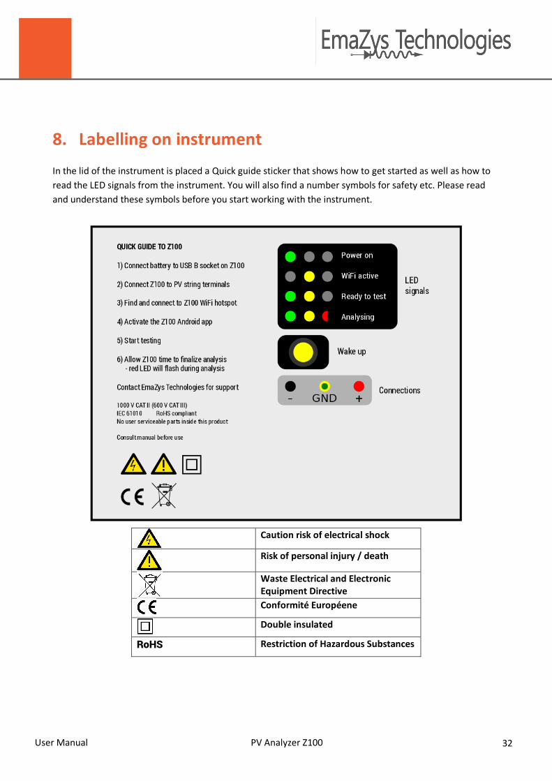
8. Labelling on instrument In the lid of the instrument is placed a Quick guide sticker that shows how to get started as well as how to read the LED signals from the instrument. You will also find a number symbols for safety etc. Please read and understand these symbols before you start working with the instrument.
Caution risk of electrical shock
Risk of personal injury / death
Waste Electrical and Electronic Equipment Directive
Conformité Européene
Double insulated
RoHS Restriction of Hazardous Substances

User Manual PV Analyzer Z100 33
9. Storage and disposal
9.1 Storage
If the PV Analyzer Z100 is taken out of service for a long time, charge and remove the battery.
9.2 Disposal
PV Analyzer Z100 must be returned to EmaZys Technologies for correct disposal. Dismount the battery before shipping.
NOTICE Important information. DO NOT try to disassemble the instrument. It must be disposed correctly according to EU regulations.

User Manual PV Analyzer Z100 34
10. Technical data
10.1 Z100 Features
Feature Z100 Production unit
Input channels PV-POS, PV-NEG, PV-GND Input range and configuration Shrouded banana, <1000V between terminals MMI Via BeagleBone WiFi-hotspot DETECTION OF FAULTS Detection of series resistance fault (Rs) Yes Detection of ground isolation fault (Riso) Yes Detection of short-circuited bypass diode Yes Detection of open-circuited bypass diode Yes
Detection of poorly producing module Yes
Detection of unprotected module Yes Detection of PV power production fault Yes LOCALIZATION OF FAULTS Localization of series discontinuity e.g. disconnect EXTERNAL to the PV modules Yes Localization of series faults e.g. disconnects/corrosion INTERNAL to PV modules Yes Localization of singular ground isolation fault Yes Localization of short-circuited bypass diode Yes Localization of open-circuited bypass diode Yes MISC. FEATURES Timer function Yes Sleep mode Yes Log of measurements to memory Yes Math (averaging, statistics) Yes
10.2 Measurement specifications
Measurement feature Z100
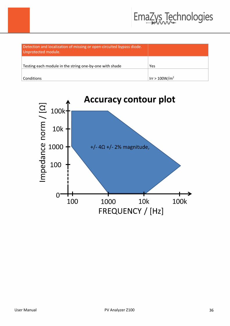
Impedance analysis Frequency coverage 100 Hz to 100 kHz
User Manual PV Analyzer Z100 35
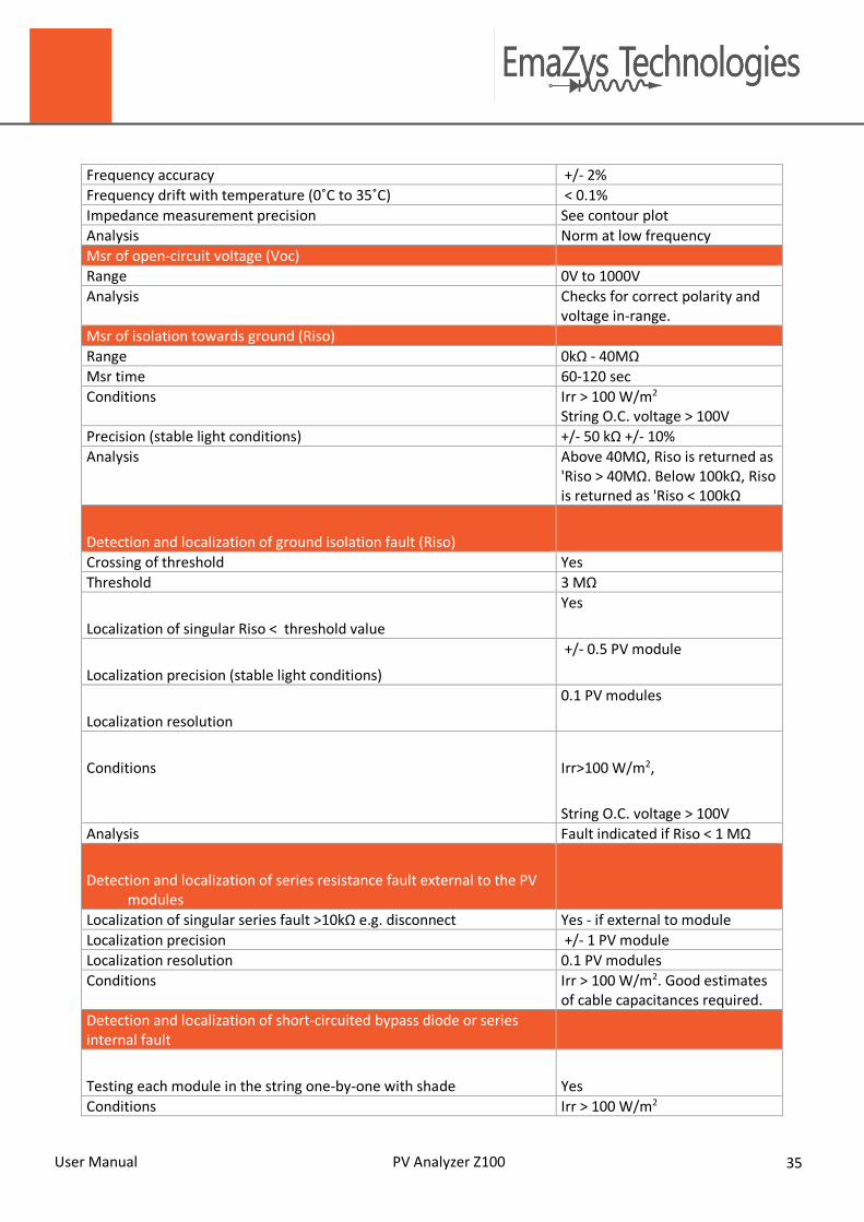
Frequency accuracy +/- 2% Frequency drift with temperature (0˚C to 35˚C) < 0.1% Impedance measurement precision See contour plot Analysis Norm at low frequency Msr of open-circuit voltage (Voc) Range 0V to 1000V Analysis Checks for correct polarity and
voltage in-range. Msr of isolation towards ground (Riso) Range 0kΩ - 40MΩ Msr time 60-120 sec Conditions Irr > 100 W/m2
String O.C. voltage > 100V Precision (stable light conditions) +/- 50 kΩ +/- 10% Analysis Above 40MΩ, Riso is returned as
'Riso > 40MΩ. Below 100kΩ, Riso is returned as 'Riso < 100kΩ
Detection and localization of ground isolation fault (Riso)
Crossing of threshold Yes Threshold 3 MΩ
Localization of singular Riso < threshold value
Yes
Localization precision (stable light conditions)
+/- 0.5 PV module
Localization resolution
0.1 PV modules
Conditions Irr>100 W/m2,
String O.C. voltage > 100V Analysis Fault indicated if Riso < 1 MΩ
Detection and localization of series resistance fault external to the PV modules
Localization of singular series fault >10kΩ e.g. disconnect Yes - if external to module Localization precision +/- 1 PV module Localization resolution 0.1 PV modules Conditions Irr > 100 W/m2. Good estimates
of cable capacitances required. Detection and localization of short-circuited bypass diode or series internal fault
Testing each module in the string one-by-one with shade Yes Conditions Irr > 100 W/m2
User Manual PV Analyzer Z100 36
Detection and localization of missing or open-circuited bypass diode. Unprotected module.
Testing each module in the string one-by-one with shade Yes
Conditions Irr > 100W/m2
User Manual PV Analyzer Z100 37
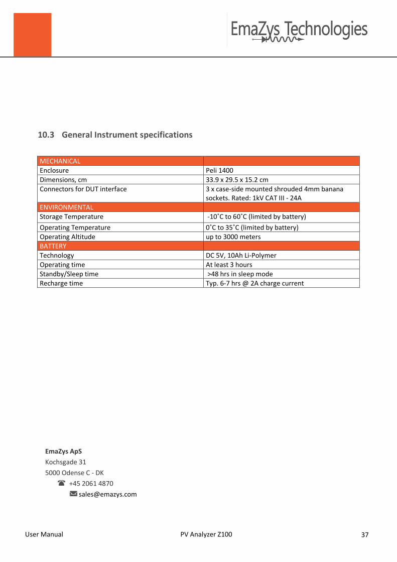
10.3 General Instrument specifications
MECHANICAL Enclosure Peli 1400 Dimensions, cm 33.9 x 29.5 x 15.2 cm Connectors for DUT interface 3 x case-side mounted shrouded 4mm banana
sockets. Rated: 1kV CAT III - 24A ENVIRONMENTAL Storage Temperature -10˚C to 60˚C (limited by battery) Operating Temperature 0˚C to 35˚C (limited by battery) Operating Altitude up to 3000 meters BATTERY Technology DC 5V, 10Ah Li-Polymer Operating time At least 3 hours Standby/Sleep time >48 hrs in sleep mode Recharge time Typ. 6-7 hrs @ 2A charge current
EmaZys ApS Kochsgade 31 5000 Odense C - DK
+45 2061 4870 [email protected]