user manual - reflex marine
TRANSCRIPT

USER MANUAL Rev 02
Issue date: 26/01/2015
Original Instructions

Rev 02 1 | P a g e
Introduction
This manual contains information for operating, maintaining and storing the TORO personnel carrier. The key to safe operations is the familiarisation and participation in planning of all crew involved. Please refer to the Crane Transfer Guidelines. This is a separate document that contains comprehensive guidance and information on each element of operation. It is for those researching, planning, managing or carrying out the safest possible crane transfers. Safe and proper use of the TORO is the responsibility of the user after having taken due regard of the information provided in this document. You should ensure that all safety measures as required by relevant legislation and by good operational practice are in place. Appropriate training should be provided for all personnel involved in the use of this device. For the purposes of this manual RML will be deemed to mean Reflex Marine. Please retain this manual for future reference. Additional copies may be obtained by contacting Reflex Marine or by downloading the latest version from www.reflexmarine.com/support.
All information disclosed in this document is the property of Reflex Marine Ltd except where otherwise stated.
Reflex Marine Ltd reserves all patent rights, design rights, manufacturing rights, copyright and sales use rights
thereto, and to any article disclosed within this document except where such rights are expressly granted to
others or where not applicable to vendor proprietary parts.
© 2015 Copyright Reflex Marine Ltd, All rights reserved.

Rev 02 2 | P a g e
Contents
Introduction ........................................................................................................................................... 1
1 Product Specifications .................................................................................................................. 4
2 Operating Parameters .................................................................................................................. 5
2.1 Overview ................................................................................................................................ 5
2.2 Recommended Operating Parameters ............................................................................... 7
3 Using the TORO ............................................................................................................................ 8
3.1 Safety Features ..................................................................................................................... 8
3.2 Passenger Instructions ......................................................................................................... 8
3.3 Entry and Exit ........................................................................................................................ 9
3.4 Deck Crew Instructions ...................................................................................................... 10
3.5 Safety Harness Procedure ................................................................................................. 11
3.6 Stretcher Mode .................................................................................................................... 13
3.7 Carrying Luggage ................................................................................................................ 14
3.8 Control of Lifting Assembly ............................................................................................... 15
4 Inspection & Maintenance ......................................................................................................... 16
4.1 Introduction ......................................................................................................................... 16
4.2 Definitions ............................................................................................................................ 16
4.3 Inspection Types ................................................................................................................. 17
4.4 Frequency ............................................................................................................................ 17
4.5 Supporting Documentation ............................................................................................... 18
4.6 Load Test Procedure .......................................................................................................... 20
4.7 Pre Use Check ..................................................................................................................... 23
4.8 Visual Inspection Checklist Form ...................................................................................... 24
4.9 Examination Checklist Form .............................................................................................. 27
4.10 Post Load Test Inspection Checklist Form ...................................................................... 31
5 Handling & Storage .................................................................................................................... 32
5.1 Stock Inspections ................................................................................................................ 32
5.2 Forklift .................................................................................................................................. 33
5.3 Crane .................................................................................................................................... 33
5.4 Securing ............................................................................................................................... 33
5.5 Inspection ............................................................................................................................ 33
5.6 Preparation for Road Transport ........................................................................................ 33
Rev 02 3 | P a g e
5.7 Shipping ............................................................................................................................... 34
5.8 Storage ................................................................................................................................. 34
5.9 Feet Deformation during Storage ..................................................................................... 34
5.10 Replacement Parts .............................................................................................................. 34
6 Replacement Parts ...................................................................................................................... 35
6.1 Introduction ......................................................................................................................... 35
6.2 Kits ........................................................................................................................................ 35
6.3 Parts identification .............................................................................................................. 36
6.4 Accessories .......................................................................................................................... 36
7 Certificates ................................................................................................................................... 37
7.1 EC Declaration of Conformity ............................................................................................ 37
7.2 ABS Type Approval ............................................................................................................. 38
8 Contact Details ............................................................................................................................ 39

Rev 02 4 | P a g e
1 Product Specifications Table 1 Product Specifications
Model No. RT4
Dimensions (Nominal)
Width 1 1988 mm
Width 2 (Across Buoyancy) 2109 mm
Height 2089 mm
Weight
Maximum Gross Mass 815 kg
Tare Weight 375 kg
Payload - SWL 440 kg
Materials
Frame 316 Stainless steel, A4 stainless steel fixings
Central Column / Lift Eye Plug 316 Stainless Steel
Other Steel Components All stainless steel except for floor grating
Floor Grating S235JR, GALVANISED TO BS 1461
Buoyancy
PE moulded shell with Polyurethane (PU)
closed cell foam fill.
Seat Base PE moulded shell with Polyurethane (PU)
closed cell foam fill.
Landing Feet EVA Foam
Operating
Temperatures Standard Model -20°C to +50°C
Suspension
Feet EVA foam feet designed to absorb hard landing impact
Seat Cushions Integral skin polyurethane seat cushion
designed to absorb hard landing impact
Seating
Seats 4 x Full Height Seats
Harnesses 2 Point, Quick Release Buckle
Grab Handles 2 Per Passenger
Lifting Points
SWL
Main 815 kg
Backup 815 kg
Handling 815 kg
Wire Rope
Lifting Assembly
Safe Working Load 2000 kg
Wire Rope Anti-rotation wire rope
Number of
Passengers
Standard 4
Stretcher Mode 2 + Stretcher
Impact
Protection
Vertical impacts Passengers are protected during heavy
landings at speeds of up to 3 m/s
Lateral impacts Passengers are protected from lateral impacts at speeds of up to 2 m/s
Stability
Horizontal 35 degrees, for a load of 1-4 passengers.
Submerged Self-Righting Up to 180° with 2 passengers. 110° with 4 passengers
Type
Approval Class
CE - 24319/D963 ABS - 09-LD408536-1-PDA
Quality System Manufactured to ISO 9001:2008
Standards
National Technical Standards UK, BS EN 1993 series: The Use of Structural Steel in Building.
Industry European Standards EC Machinery Directive EN 14121-1, BS EN 12100-10
Load Test – ILO152 / LOLER
National Regulations UK, PUWER / LOLER

Rev 02 5 | P a g e
2 Operating Parameters
2.1 Overview
The TORO has been designed to ensure passenger safety in the most demanding conditions.
There are a large number of factors that affect the safe conduct of marine personnel transfers. These include crew skill and experience, met-ocean conditions, landing areas, vessel station keeping capability and response to sea conditions, visibility and line of sight. A combination of many factors will determine the risk involved in a transfer.
2.1.1 Operational Sea State
The TORO has inbuilt cushioning to minimise shock loads and maximise passenger comfort during take-off and landing. The maximum recommended significant wave height is determined by the maximum relative velocity between the TORO (or crane hook) and the landing deck.
The calculated sea states detailed below are based on vertical collision speeds and bio-mechanical considerations. They reflect the ability to withstand such impacts with minimal risk of injury to the human body. However, there are many additional factors that may affect the safety of crane transfer operations. These include vessel station-keeping, crew competence, wind speed and visibility. The operator should always refer to general guidelines on crane transfers operations to assess overall risks.
Technical note:
The calculation for relative velocity used here is based on the European offshore crane standard, BS EN 13852-1:2004. Whereby the maximum anticipated relative velocity between a load and a vessel deck, is given by the following; Relative velocity = (0.5*Hook velocity)1 + √ (Vessel deck velocity 2 + Boom tip velocity 2) 1 Equal to 1.67 m/s (100 m/min) for lifts below 5 tonnes. Higher crane hook speeds may be available, and it follows that the higher the available crane speed the higher the possibility of a heavy landing or take off. However, with a qualified Crane Operator, it is considered unlikely that the TORO will be landed at full hook speed on a deck rising at full speed. If there are concerns about heavy landings, operators may wish to consider the following methods to reduce
risks; dry runs without passengers, landing in centre of deck where there is less vessel movement,
transferring fewer passengers to increase damping, using a hook speed indicator.

Rev 02 6 | P a g e
Table 2 TORO Operating Parameters
1.5
2.5
3
3.5
1
1.5
2
2.5
0 1 2 3 4 5
Vessel to Vessel
FPSO to Vessel
Semi-sub to Vessel
Platform to Vessel
Significant Wave Height (m)
TORO Sea State Limits
Normal Risk Increased Risk Off Limits
Note:
Recommended Operating Limit - This is the envelope in which it would normally be considered safe subject to due consideration of other
risk factors.
TORO Performance Limit - This envelope is defined by the performance limits of the capsule and the theoretical translation to significant
wave height by EN13852-1:2004. However it is assumed that in such elevated sea states other risk factors may become
substantial. Operations should not normally be performed in this range without conducting a thorough risk assessment. Contact Reflex
Marine if you need assistance.
Outside operating Limit - It is not recommended - sea states are above the safe design envelope of the capsule.

Rev 02 7 | P a g e
2.2 Recommended Operating Parameters
Table 3 Recommended Operating Parameters
Parameter Recommendation
Wind Speed 40 knot (equivalent to 20 m/s)
Visibility Crane Operator should have a clear view of the pickup and set down areas.
Vessel Motion Pitch 10⁰ Roll 10⁰
Vessel Station-Keeping Able to maintain position within a 5 m (16 ft) radius. If a high risk of the vessel losing position exists, disconnect the carrier for passenger embarkation.
Landing Area Must be clear of obstructions, protrusions, and trip and fall hazards.
Landing Area – Ice / Spills
Ice and spills must be cleaned from landing area prior to transfer.
Landing Area on Vessel
6 m x 6 m (20 ft x 20 ft) landing area is recommended, equivalent to 2m (6.5 ft) clearance all round. Smaller landing areas may be used provided a risk assessment of factors such as deck hazards, weather, sea state, vessel size, station-keeping is carried out.
Landing Area on Installation
4 m x 4 m (13 ft x 13 ft) clear landing area is recommended based on additional 1m entry and exit path on all sides.
Crane Requirements Crane must be suitable for lifting personnel and properly maintained.
Communications Radio communication must be established between the Crane Operator and the vessel Deck Crew and Master.

Rev 02 8 | P a g e
3 Using the TORO
3.1 Safety Features
Protected Seating Position: Seats are positioned directly behind the buoyancy panels providing maximum protection and minimised sense of exposure. The arrangement of the seats and individual entry / exit points allow rapid access and egress, allowing faster and more efficient transfers. Fall Protection: Lap strap system and grab handles protect from the risk of falling during transfer. A 3 point harness is available as an optional accessory. Vertical impact protection:
i. Semi-upright seat position, soft pommel seats and soft headrest
ii. Soft EVA foam feet
Lateral impact protection:
i. Stainless steel frame
ii. Buoyancy panels
iii. High backed headrest designed to reduce risk of whiplash
iv. Grab handles and pommel shaped seat cushion for secure seating position
Floatation: Buoyancy panels ensure the TORO floats with passengers above the water line. When in stretcher mode the stretcher will not be above the water line.
3.2 Passenger Instructions
i. Enter carrier and take the seat to the left
ii. Fasten seat harness
iii. Keep hands and feet inside the carrier
iv. Hold the grab handles to keep body stabilised
v. Place feet onto the floor in front of the buoyancy panel
vi. Bear weight slightly onto feet in order to adopt a comfortable semi squat position especially during landing and take-off

Rev 02 9 | P a g e
3.3 Entry and Exit
Passenger entry to and exit from the TORO should only be
conducted with the carrier in a stable position on deck as
advised by the crane operator to the deck crew member in
charge of the transfer operation.
Note: All exiting passengers must be clear of the carrier before
any new passengers attempt to board.
Each individual seat has a dedicated entry / exit point to prevent
confusion and ensure an efficient operation. All passengers must
enter and exit from the same direction. Chevrons on the
buoyancy panels are present to indicate the direction of entry.
Entry
When advised to do so by the deck crew, passengers should proceed as directed to one of the four entrances (note trip hazard). When instructed, all passengers should enter the carrier and take the seat to their left.
Passengers should ensure they are securely seated and ensure the seat harness is securely fastened. Grab handles are provided on the tubular upright members either side of the buoyancy panel and passengers should grip these firmly or the harness straps whenever seated.
Exit Following landing and when advised to do so by the deck crew, passengers should unfasten the safety harness, stand and exit (note trip hazard) to their left. Passengers should move clear of the carrier as directed by the deck crew, ensuring they remain clear of the lifting assembly.

Rev 02 10 | P a g e
3.4 Deck Crew Instructions
Briefings
Deliver passenger briefings prior to every transfer lift which should contain the following
information:
i. Location specific instructions
ii. Loading and unloading procedures
iii. Emergency procedures
iv. Potential hazards
v. Seating position
Other Responsibilities
i. Highlight potential hazards to passengers e.g. trip hazards during entry/exit
ii. Remain alert from any hazards as they arise and take appropriate action
iii. Check that passengers’ harnesses are secure and correctly fitted
iv. When the carrier is in the static position on deck for passenger entry and exit, the
wire rope lifting assembly will be in a static position and may obstruct one or more of
the entry / exit points. Ensure passengers remain clear of the wire rope lifting
assembly. Deck crew may need to clear the lifting assembly from carrier entrances.

Rev 02 11 | P a g e
3.5 Safety Harness Procedure
The TORO comes with lap straps fitted as standard, however 3 point harnesses are available as an optional accessory.
To make passenger entry more efficient, where possible, deck crew or passengers should loosen all harnesses prior to
entering the carrier. All passengers should be familiar with seating procedure and practice entry prior to operations.
3.5.1 Lap Belt
Fasten
Step 1 Take the lap fastener clip
and feed through eye.
Step 2 Fold over the clip and the safety belt is
secure
Step 3 Next pull the
LOWER straps first
Unfasten
Step 1 Fold back
buckle
Step 2 Pull apart
harness straps
Step 6 Exit the carrier

Rev 02 12 | P a g e
3.5.2 3 Point Harness
Fasten
Step 1
Enter the carrier
from the right hand side of your
chosen seating position
Step 2
Pull the harness
straps over your shoulders and
pull the buckle together
Step 3
Take the lap
fastener clip and feed through eye
Step 4
Fold over the clip and the safety
belt is secure
Step 5
Next pull the LOWER straps
first
Step 6
Then the UPPER straps to make a
tight fit
Unfasten
Step 1
Fold back buckle
Step 2
Pull apart harness
straps
Step 3
Exit the carrier to
the left

Rev 02 13 | P a g e
3.6 Stretcher Mode
The following steps outline the procedure to convert the TORO into stretcher mode.
3.6.1 Converting to Stretcher Mode
It’s very easy to use the TORO rapidly for medEvacs
using a stretcher.
The stretcher can be fitted in the TORO without any
reconfiguration of the seating arrangement. The
stretcher is positioned for transit on the floor
underneath the seating and between the seat bases.
Important: The stretcher passenger would be
below the waterline in the very rare event that
the TORO were immersed. It is important to review the risk when performing
stretcher based transfers and ensure that awareness is high and that emergency
procedures are in place.
3.6.2 Stretcher Positioning
i. The TORO should be positioned on a flat surface in an area which provides sufficient
space to correctly align the stretcher and guide it into position.
ii. Ensure that the floor grating is clear of obstructions before positioning the stretcher.
iii. Ensure the injured person is securely strapped into the stretcher.
iv. Using three or four persons to lift the stretcher, align the stretcher with the space
between the seat bases. The stretcher is to be placed under the seats aligned with
the space between buoyancy modules ‘A’ and ‘B’ or between buoyancy modules ‘C’
and ‘D’. Note: Ensure safe manual handling when lifting the stretcher.
v. Place the feet-end of the stretcher onto the floor grating and slide the stretcher into
position as shown in figure 2 below. Secure the stretcher in position with the four
straps provided as shown in Figure 2.
vi. The top cross beam may be used as a support point for an intravenous drip.
vii. The stretcher is held in position laterally by the seat bases. Secure the head and feet
ends of the stretcher to the floor with the four straps provided to prevent
longitudinal movement.
Figure 1 TORO Stretcher Mode

Rev 02 14 | P a g e
viii. Important: Prior to transfer ensure the stretcher is firmly secure.
ix. The casualty can be accompanied by a maximum of two passengers during the
transit. Passengers should occupy seating positions marked as ‘P’ (as shown in figure
2 below) when accompanying a stretcher casualty.
3.7 Carrying Luggage
The TORO is not supplied with luggage storage. All luggage items should be transferred separately in dedicated luggage container or cargo net.
P
Figure 2 TORO Stretcher Positioning

Rev 02 15 | P a g e
3.8 Control of Lifting Assembly
The TORO is designed to stay firmly on the deck of the vessel whilst passengers are
entering or leaving the carrier. The Crane Operator must maintain slack in the line upon
landing to allow for the vessel movement.
Table 4 Control of lifting assembly
Parameter Recommendation
Ideal Sling Length The recommended limits in this section are based on the use of the standard wire rope lifting assembly length of 30 ft (9 m).
Shorter Slings
For the use of shorter lifting assemblies an additional risk assessment combined with dry runs should be performed to establish safe operational routines and weather conditions. Using a shorter sling set also increases risks associated with the hook block being in close proximity to the capsule
Table 5 Sling lengths
Sling Length Recommended
Slack Allowable Drift
Distance to the Crane Hook
30 ft 10 ft 22.4 ft 20 ft
20 ft 10 ft 17.3 ft 10 ft
10 ft 8 ft 9.8 ft 2 ft
Figure 3 Lifting assembly slack

Rev 02 16 | P a g e
4 Inspection & Maintenance
4.1 Introduction Following the recommended procedures set out in this section will help to ensure safe operation of the TORO.
4.2 Definitions
Transfer Lift
A transfer is defined as one pickup and put down when passengers are on board, or when
the unit carries more than its tare weight.
Usage Category
This is defined by the number of transfer lifts per year. There are four different usage
categories from low to very high.
Critical Parts
These are an identified set of load bearing parts.
Suspension System
These are an identified set of parts that are part of the suspension system.
Competent Person
A competent person is a person who has appropriate practical and theoretical knowledge
and experience of the equipment. This will enable them to detect defects and weaknesses
and to assess their importance in relation to the safety and continued use of the equipment.
It is recommended that the competent person is sufficiently independent and impartial to
allow objective decisions to be made.
Non Destructive Testing
Although not considered necessary, some operators choose to adopt a dye penetrant crack
inspection prior to any re-installation of a critical part.

Rev 02 17 | P a g e
4.3 Inspection Types
Table 6 Inspection Types
Inspection Type
Description
Pre-use Check A check of key areas prior to each use without dismantling the assembly. Carried out by a competent person.
Visual A careful and critical assessment of the components, carried out by a competent person without dismantling the assembly.
Examination
A careful and critical assessment of the components, carried out by a competent person. This should include dismantling the assembly and performing a visual assessment of the condition of each component, supplemented by other means such as measurement and non-destructive testing as considered necessary. For lifting assemblies this should include a visual inspection of the condition of each leg.
Post Load Test Inspection
A careful and critical assessment of the components following a proof load test. Carried out by a competent person without dismantling the assembly.
All inspections should:
i. Be performed by a competent person
ii. Be carried out as per the frequency indicated in the usage table
iii. Be formally recorded
4.4 Frequency The recommended frequency and type of inspection, test and maintenance is shown in Table 7. (SEE OVER). Please note:
i. If any doubt exists regarding the usage then the maintenance strategy should revert
to a more conservative higher usage category. This must also be considered if there
is any concern over heavy impacts or overloads.
ii. This recommendation applies to change out of components parts only and does not
replace or alter the inspection intervals as prescribed by the relevant legislation.
iii. The check, inspection, examination and test routine as detailed in this document
should always be carried out on schedule.
iv. Where the carrier has experienced heavy vertical or lateral impacts, or sustained
substantial damage, a detailed examination should be carried out to ensure integrity
before conducting any further lifts. Details of all damage should be recorded in a
damage report. Details of the cause of the damage should also be recorded, if known.

Rev 02 18 | P a g e
If damage to the frame has occurred, welds should be examined for cracks using dye
penetrant.
v. Details of all repairs or modifications carried out should be recorded and copies of
damage and repair / modifications reports should be sent to the party controlling the
use of the TORO.
vi. Lifting assembly covers should be removed if the wire rope lifting assembly is
removed from service.
vii. Contact RML or an approved partner for technical advice on inspection, testing or
maintenance. It is always helpful to provide detailed photos and reports along with
any query to [email protected].
4.5 Supporting Documentation
Customer drawing pack
Every TORO comes with a drawing pack that contains all of the relevant drawings to aid in
its maintenance. This pack contains the following:
i. Assembly drawings ii. Replacement parts, kit drawings iii. Torque settings iv. Operational stickers v. Bill of materials
Certification pack
Every TORO comes with a certification package which includes, but not limited to,
manufacturer’s declaration of conformity, all of the critical parts certificates, load test
certificates and the third party release note and checklist.
If any further certification is required please contact RML.
Component certification
RML retains copies of the certification for all units and components involved in their manufacture. Replacement copies are available on request.

Rev 02 19 | P a g e
Table 7 TORO Inspection and Maintenance Recommendations
TORO RECOMMENDED INSPECTION AND MAINTENANCE SCHEDULES
Usage Category
No of Transfer Lifts per year
Pre Use Check
Visual Inspection
Examination
Wire Rope Lifting
Assembly Replacement
Critical Parts Replacement
Suspension System
Replacement2
Unit Replacement1
Load Test
Post Load Test Visual
Inspection
Low <100
Prior To Every Use
6 months 12 months 12 months 36 months 4 Years 12 years
Medium 100 - 500
6 months 12 months 12 months 24 months 3 Years 8 years
High 500 - 2000
3 months 12 months 6 months 12 months 2 Years 6 years
Very High 2000 - 5000
3 months 6 months 3 months 6 months 1 years 4 years
1This may be extended subject to a ‘condition & service assessment’ carried out by Reflex Marine or an Approved Partner
2Comprises of landing feet and seat cushions

Rev 02 20 | P a g e
4.6 Load Test Procedure Table 8 Load Test Requirements
Question Response
When must a Proof Load Test be conducted?
i. After replacement of any critical parts. Does not apply to replacement of lifting assemblies.
ii. After any suspected damage arising from overloading or impact.
iii. If the history of the carrier is uncertain. iv. If the inspection data plate is missing, illegible or out of
date.
Who can conduct this test?
i. Independent 3rd party. ii. A competent and certified test person.
Does this test require a formal record?
Yes.
What equipment is required to perform this test?
i. Loading weights or sand bags (1,255 kg). ii. Calibrated weighing scale or load cell. iii. Lifting equipment certified for > 5 Tonnes SWL. iv. A ladder or top access platform. v. An inspection frame or floor matting. vi. Good lighting.
Main Lift Point and Backup Lift Point Load Test Procedure
Table 9 Load Test Instructions for Main Lift Point and Backup Lift Point
Item Instruction
Components Under Test
i. Main Lift Point / Backup Lift Point ii. Central Column Load Bearing Assembly. iii. Seats and Floor Structure.
Test Proof Load 1255 kg ( 2761 lb)
Test Proof Load Distribution
At the discretion of the competent person the proof load may be
applied to the TORO either solely on the floor or split between the
floor and seats. For the latter the recommended distribution is;
i. 440 kg (970 lb) on seats spread equally between them. Seats and harnesses should be protected prior to loading with weight. If solid test weights are used the seats may be folded to create a flat platform. Wooden boards placed on folded seats will increase area for test weights, the test load should be concentrated towards the centre of the unit to prevent damage to the seat.
ii. 815 kg (1793 lb) placed on the floor and distributed evenly.
Basis of Test Proof Load
Twice Maximum Gross Weight, less Tare Weight*= 2 x 815 kg – 375 kg = 1255 kg ( 2761 lb)
Crane Hook Load 1630 kg ( 3586 lb)
Test Method Lift the unit and hold static for 3 minutes.
Order 1st - Main Lift Point 2nd - Backup Lift Point
* Note: The tare weight of the TORO is approximately 375 kg (827 lb) but may vary slightly. Each TORO must be weighed prior to load test

Rev 02 21 | P a g e
Handling Eye Load Test Procedure
Table 10 Load Test Instructions for the Handling Eye
Item Instruction
Components Under Test
i. Handling Point ii. Central Column Load Bearing Assembly. iii. Floor Structure.
Test Proof Load 375 kg ( 827 lb)
Test Proof Load Distribution
At the discretion of the competent person it is recommended that
the proof load is applied to the floor of the TORO;
i. 375kg (827 lb) placed on the floor and distributed evenly.
Basis of Test Proof Load
2 x Tare Weight*= 2 x 375 kg = 750 kg (1653 lb)
Crane Hook Load 750 kg (1653 lb)
Test Method Lift the unit and hold static for 3 minutes.
Inspection Data Plate
An inspection data plate will be issued and attached by the test house, which should show:
i. Tare weight (kg)
ii. Pay load / SWL (kg)
iii. Maximum gross load (kg)
iv. The load test date (DD/MMM/YYYY)
v. Test load (kg)
vi. Serial number: RT4-XXX (where XXX is unit I.D. No)
vii. Model number: RT4
viii. Entry into service date (DD/MMM/YYYY)

Rev 02 22 | P a g e
Marker Plate
i. Model number: RT4
ii. Serial number: RT4-XXX (where XXX is unit I.D. No)
iii. Date of manufacture (DD/MM/YYYY)
iv. Tare weight (kg)
v. Pay load / SWL (kg)
vi. Maximum gross load (kg)
vii. Maximum number of passengers (standard & stretcher mode)
Certification Plate
The TORO is indelibly marked with the following information:
i. CE Mark
ii. ABS Type Approval Mark

Rev 02 23 | P a g e
4.7 Pre Use Check

Rev 02 24 | P a g e
4.8 Visual Inspection Checklist Form
TORO Visual Inspection Checklist Page 1 of 3
Unit Serial Number This Inspection Date Inspected by
Usage Category Last Visual Inspection Position/ Company
Installation / Vessel Last Examination Signature
Avg. No of Transfers /
Year Last Load Test
Original Inspection
record filed in
Item
No Description
Comment / Serial
Number/ Colour Code
Pass /
Fail
Verified
By
1.
Wire Rope Lifting Assembly (Critical Part)
The wire rope lifting assembly (including attachments) must be visually examined by a Competent Person.
Note: High visibility cover must be completely removed to allow inspection of steel wire rope components. It should be replaced according to the usage. This may be as frequently as every 3 months.
Irrespective of apparent condition the lifting assembly should be replaced at least every 12 months.
2. Main Lift-Eye Plug (Critical Part)
Visually inspect in situ for any signs of wear, cracks, deformation or other damage.
3.
Main Lift-Eye Plug M16 Bolts (Critical Part)
Visually inspect the two M16 lifting eye bolts, nuts, split pins and tamper proof seals that connect the main Lift-Eye plug to the central column (through the lifting bolt retaining sleeve) for wear or damage.
Check items are present and not loose.
4. Back-Up Lift-Eye
Visually inspect for any wear or damage and check that the split pin and tamper proof seal are intact.
5.
Handling Eye
Visually inspect for any wear or damage and check that the split pin and tamper proof seal are intact.

Rev 02 25 | P a g e
TORO Visual Inspection Checklist continued… Page 2 of 3
Item No
Item No Item No Item No
Item No
6. Seat Cross Beam M16 bolts (Critical Part)
Visually inspect for any wear or damage and check that the nut, bolt and washer are intact.
7. Seat Cross Beam Assembly
Visually inspect for any wear or damage and check that the nut, bolt and washer are intact.
8. Top Cross Beam
Visually inspect the top cross beam for any deformation, twisting, misalignment or impact damage.
9. Frame and Buoyancy
Visually inspect for any damage and ensure that all bolts and fasteners are tight and fully secure.
10. Landing Feet
Examine the feet to ensure that they are in good condition and that they are properly secured to the
capsule. Do not go underneath an active lift
Notes: i. Measure height of foot and replace if under 100 mm in height
ii. Small (20 mm in length) cuts are acceptable but feet should be replaced when damage larger than 20mm is present.
Foot
A:
B:
C:
D:
11. Seat Cushions
For either Velcro or bolt through fitting, check the cushions are secure and in good condition.
Seat Cushion
A:
B:
C:
D:
12. Seat Harness Security
Visually inspect the seat harness attachment points and the harness webbing for any signs of wear, fraying or damage. Check that attachment points are secure.
Harness
A:
B:
C:
D:

Rev 02 26 | P a g e
TORO Visual Inspection Checklist continued… Page 3 of 3
Item No
Item No Item No Item No
Item No
13 Seat Harness (sit-in)
Check all seat harness buckles to ensure each is functioning correctly. (Inspector to sit in each seat and
check fastening and unfastening of each harness).
Harness
A:
B:
C:
D:
14 Inspection data plate
Check the date of the last examination/ inspection to ensure the unit will remain in compliance with
requirements for at least 6 months.
Storage
15. Storage
Check the storage cover is in good condition and not showing any signs of UV or wind degradation.
Storage off the ground , use of spacer chocks whilst not in use
16. Replacement Parts Stock
Check condition of all associated replacement parts and accessories. Lifting assemblies should be stored in an appropriate dry place without high visibility cover fitted.
Reports Complete Y/N
17. Documentation / Report including Photographic Report
NOTES:

Rev 02 27 | P a g e
4.9 Examination Checklist Form
TORO Examination Checklist Page 1 of 4
Unit Serial Number This Inspection Date Inspected by
Usage Category Last Visual Inspection Position/ Company
Installation / Vessel Last Examination Signature
Avg. No of Transfers /
Year Last Load Test
Original Inspection
record filed in
Item
No Description
Comment / Serial
Number/ Colour Code
Pass /
Fail
Verified
By
1.
Wire Rope Lifting Assembly (Critical Part)
Replace the wire rope lifting assembly according to the usage. This may be as frequently as every 3
months. Irrespective of apparent condition the lifting assembly should be replaced at least every 12
months.
2.
Main Lift-Eye Plug (Critical Part)
Remove and visually inspect the main lift-eye plug for any signs of damage or strain. Replace according to the usage of the TORO or on the recommendation of a Competent Person / Inspector.
3.
Main Lift-Eye Plug M16 Bolts (Critical Part)
Remove and visually inspect the two M16 main lift-eye plug securing bolts for any signs of damage or
strain. Visually inspect the two M16 holes in the central column tube for signs of damage or strain.
Replace appropriate parts according to the usage of the TORO or on the recommendation of a Competent Person / Inspector. Refer to customer drawing pack for torque settings
4.
Back-Up Lift-Eye
Inspect the back-up eye in situ, nut, split pin and tamper proof seal. Replace on the recommendation of
a Competent Person / Inspector. Refer to customer drawing pack for torque settings
5.
Handling Eye
Visually inspect for any wear or damage and check that the split pin and tamper proof seal are present.

Rev 02 28 | P a g e
TORO Examination Checklist Continued… Page 2 of 4
Item
No Item No Item No
Item
No Item No
6.
Seat Cross Beam M16 bolts (Critical Part)
Visually inspect for any wear or damage and check that the nut, bolt and washer are intact.
Refer to customer drawing pack for torque settings
8.
Seat Cross Beam Assembly
Visually inspect for any wear or damage or strain and check that the nut, bolt and washer are present
and secure.
Check stand tubes and upper and lower connections to seat cross beam and floor.
9. Top Cross Beam
Visually inspect the top cross beam for any deformation, twisting, misalignment or impact damage.
10. Frame and Buoyancy
Visually inspect for any damage and ensure that all bolts and fasteners are tight and fully secure.
11.
Landing Feet
Examine the feet to ensure that they are in good condition and that they are properly secured to the
capsule. Do not go underneath an active lift.
Notes:
i. Measure height of foot and replace if under 100 mm in height ii. Small (20 mm in length) cuts are acceptable but feet should be replaced when
damage greater than 20mm is present
iii.
Foot
A:
B:
C:
D:
12.
Seat Cushions
For either Velcro or bolt through fitting, check the cushions are secure and in good condition.
Seat Cushion
A:
B:
C:
D:

Rev 02 29 | P a g e
TORO Examination Checklist Continued… Page 3 of 4
Item
No Item No Item No
Item
No Item No
13.
Seat Harness Security
Visually inspect the seat harness attachment points and the harness webbing for any signs of wear, fraying or damage. Check that attachment points are secure.
Harness
A:
B:
C:
D:
14.
Seat Harness (sit-in)
Check all seat harness buckles to ensure each is functioning correctly. (Inspector to sit in each seat and
check fastening and unfastening of each harness).
Harness
A:
B:
C:
D:
15. Inspection data plate
Renew the load test plate after completion of approved load test.
13. Stickers – Check that all of the stickers on the unit are in good condition and that none are missing or damaged. The sticker location drawing can be found in the drawing pack.
14. Stretcher Fittings – Test fit a stretcher to ensure that all of the fittings are present and in good
condition.
16
Full Load Test
A full load test must be conducted by an independent test house company, nationally recognised and in
accordance with ILO 152.
17 Post Load Test Visual Inspection
Conduct and report a post load test visual inspection.
Storage
16.
Storage - Check the storage cover is in good condition and not showing any signs of UV or wind degradation.
Storage off the ground , use of spacer chocks whilst not in use

Rev 02 30 | P a g e
TORO Examination Checklist Continued… Page 4 of 4
Item No
Item No Item No Item No
Item No
17. Replacement Parts Stock - Check condition of all associated replacement parts and accessories. Lifting assemblies should be stored in an appropriate dry place without high visibility cover fitted.
Other
19. Clean – Has the unit been cleaned
Reports Complete Y/N
18. Documentation / Report including Photographic Report
NOTES:

Rev 02 31 | P a g e
4.10 Post Load Test Inspection Checklist Form
Unit No This Inspection Date Inspected by
Usage Category Load Test Date Position/ Company
Installation / Vessel Load Test Report/Ref Signature
Avg No of Transfers / Year Load Test Authority Original Inspection record filed in
Item
No Description Comment
Pass /
Fail
Verified
By
1. Main Lift-Eye Plug (Critical Part)
Visually inspect in situ for any signs of wear, cracks, deformation or other damage.
2. Main Lift-Eye Plug M16 Bolts (Critical Part) Visually inspect the two M16 lifting eye bolts, nuts, split pins and tamper proof seals that connect the
main Lift-Eye plug to the central column (through the lifting bolt retaining sleeve) for wear or damage.
3. Back-Up Lift-Eye Visually inspect for any wear or damage and check that the split pin and tamper proof seal are intact.
4. Top Cross Beam
Visually inspect the top cross beam for any deformation, twisting, misalignment.
5. Handling Eye
Visually inspect for any wear or damage and check that the split pin and tamper proof seal are intact.
6. Seat Cross Beam M16 bolts (Critical Part) Visually inspect for any wear or damage and check that the nut, bolt and washer are intact.
7. Seat Cross Beam Assembly
Visually inspect for any wear or damage and check that the nuts, bolts and washers are intact.
8. Frame and Buoyancy
Visually inspect for any damage and ensure that all bolts and fasteners are tight and fully secure.
9. Inspection data plate- Check the date of the last load test has been correctly inserted and is indelibly legible.
Reports Complete Y/N
10. Documentation / Report including Photographic Report
NOTES:
Rev 02 32 | P a g e
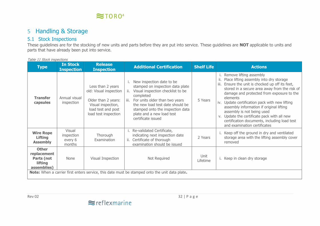
5 Handling & Storage 5.1 Stock Inspections These guidelines are for the stocking of new units and parts before they are put into service. These guidelines are NOT applicable to units and parts that have already been put into service. Table 11 Stock inspections
Type In Stock
Inspection Release
Inspection Additional Certification Shelf Life Actions
Transfer
capsules
Annual visual
inspection
Less than 2 years old: Visual inspection
Older than 2 years: Visual inspection,
load test and post load test inspection
i. New inspection date to be
stamped on inspection data plate ii. Visual inspection checklist to be
completed
iii. For units older than two years the new load test date should be
stamped onto the inspection data plate and a new load test
certificate issued
5 Years
i. Remove lifting assembly
ii. Place lifting assembly into dry storage
iii. Ensure the unit is chocked up off its feet, stored in a secure area away from the risk of
damage and protected from exposure to the elements
iv. Update certification pack with new lifting assembly information if original lifting
assembly is not being used
v. Update the certificate pack with all new certification documents, including load test
and examination certificates
Wire Rope Lifting
Assembly
Visual
inspection
every 6 months
Thorough
Examination
i. Re-validated Certificate,
indicating next inspection date
ii. Certificate of thorough examination should be issued
2 Years i. Keep off the ground in dry and ventilated
storage area with the lifting assembly cover
removed
Other replacement
Parts (not
lifting assemblies)
None Visual Inspection Not Required Unit
Lifetime i. Keep in clean dry storage
Note: When a carrier first enters service, this date must be stamped onto the unit data plate.

Rev 02 33 | P a g e
5.2 Forklift Care should be taken when handling the TORO with a forklift truck to avoid damage the
underside (landing feet, cross braces or base of the central lifting column). Alternatively the
capsule may be secured to a pallet specifically designed for use with forks.
5.3 Crane When lifting the TORO with short chain or strop, a temporary shackle should be fixed to the handling lifting point. Care must be taken not to damage the lifting assembly. A shackle should not be fitted through the thimble of the lifting assembly eyes.
5.4 Securing For deck fastening, use the peripheral braces around the floor grating.
5.5 Inspection Before and after transportation the TORO must be inspected to check for damage sustained in transit. The unit must not be used if any structural damage is observed. If any damage has been observed please complete a visual inspection to determine the extent of the damage.
5.6 Preparation for Road Transport Prior to shipping, the seat harnesses must be secured by securing the buckle together and then tightening the harness straps. This will prevent seat harnesses flapping and damaging the seating area. It is recommended that the TORO is covered for shipping either with a TORO weatherproof protective cover or other heavy duty tarpaulin material.

Rev 02 34 | P a g e
5.7 Shipping The TORO will fit in a standard or high-cube container. If the TORO is transported on a flat rack it must be secured. Recommended securing points are the radial / peripheral floor braces. To protect it from excess loading, the main Lift-Eye must not be used as a securing point. Feet must be supported to prevent collapse; this can be done by placing suitable chocks or props under the unit.
5.8 Storage The TORO has been designed to cope with the harsh conditions on an offshore installation or vessel; however it is important to protect the unit as much as possible from any hazardous elements and UV degradation. It is recommended that the TORO is stored under a TORO weatherproof cover whilst not in use.
5.9 Feet Deformation during Storage
Prolonged periods of exposure to hot decks and self-weight can cause permanent set deformation of the elastomeric feet. If the carrier is to be stored for prolonged periods a set of chocks should be used to lift the feet away from the deck. Any chocks used should fit properly underneath the main base frame to ensure that any exposed bolt heads are not impinged. The chocks can be pre-laid on the deck ready for landing.
5.10 Replacement Parts
Replacement parts should be stored in dry clean environments and be suitably labelled and tagged.

Rev 02 35 | P a g e
6 Replacement Parts
6.1 Introduction Replacement parts can be supplied as individual items or as appropriate kits. Prior to ordering any replacement parts or kits, establish the serial number which is stamped on the data plate. The serial number is RT4- XXX where XXX represents a three digit number. RML holds replacement parts and accessories in stock. We are able to supply most individual components. A full list of parts is contained in the customer drawing pack, which is issued with every unit. It may be advisable to hold an inventory of frequently replaced parts. This will help to ensure the continued safe operation of the carrier. Minimum stock quantities will be influenced by:
i. Remoteness of location ii. Downtime implications iii. Criticality of maintaining crew and emergency response (Medevac) access. iv. Usage v. Customs processing time vi. Delivery cost for small parts
RML can recommend stock items and quantities for your operation. It is recommended that only genuine OEM parts (including lifting assemblies) are
used.
6.2 Kits The following kits are available for routine and non-routine maintenance. Ordering an appropriate kit is more economical than replacing individual parts.
Kit Name Part Number Contents
Lifting Assembly Kit RT-SK-01 Wire Rope Lifting Assembly Lifting Assembly Cover Associated Fixings
Replacement Parts Kit RT-RPK-01 Critical Parts Minus The Wire Rope Lifting Assembly
Critical Part Kit RT-CPK-01-30 Critical Parts including lifting assembly
Harness Kit RT-RHK-01 4 X Harnesses plus associated Fixings
3 Point Harness Kit RT-RHK-02 4 X Harnesses plus associated Fixings
Landing Foot Kit RT-LFK-01 4 X Feet plus associated fixings
Full Service Kit RT-FSK-01-30
1x Lifting Assembly Kit 1 X Replacement Parts Kit 1 X Landing Foot Kit 1 X back up eye refurbishment kit
Suspension Kit RT-TSK-01 4 x Seat Cushions 4 x Landing Feet Associated Fixings
Handling eye refurbishment kit
RT-HEK-01 1 x long shank eye bolt plus associated fixings
Back up eye refurbishment kit
RT-BEK-01 1 x back up pad eye plus associated fixings

Rev 02 36 | P a g e
6.3 Parts identification
Each assembly or part is assigned a part number which provides the unique identification of
the part /assembly.
Where material grades and material traceability are deemed to be safety critical these components will be allocated unique component numbers which will be stamped or etched as required. Components that require unique identification are referenced in the parts list in the customer drawing pack. For bolts, where etching is impractical, batches will be colour coded and a note added to the mill certificate to identify the colour used.
6.4 Accessories The following accessories are available from RML to maximise operational effectiveness. They can be supplied with the carrier or ordered separately.
Strobe Light Provides greater visibility at night and in poor weather conditions. High-intensity: light weight, waterproof to 300 m, Flash Rate 50 per min and also provides 6 mile visibility. Fitted to the top cross beam. Note: This strobe is not certified for use in hazardous areas. A zoned strobe light is available on request.
Basket Stretcher Essential for conducting emergency medical transfers, Reflex Marine supply a rigid stretcher that is compatible with the TORO.
Protective Cover A silver reflective protective cover which is made of flame resistant fabric (BS7837) and protects against degradation from UV light and the weather.
Three Point Harness Three point harnesses are available for added passenger security (as opposed to the standard lap strap).
For a complete list of accessories please contact RML
Rev 02 37 | P a g e
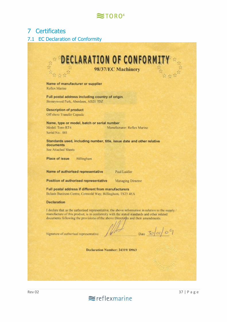
7 Certificates
7.1 EC Declaration of Conformity

Rev 02 38 | P a g e
7.2 ABS Type Approval

Rev 02 39 | P a g e
8 Contact Details
Address: Head Office Reflex Marine Old School House School Hill Shortlanesend Truro TR4 9DU UK Telephone: +44 (0)1872 321155 Email Addresses: General enquiries – [email protected]
Order enquiries (sales & replacement parts) – [email protected]
Accounts Department – [email protected]