user manual securope 2012 horizontal - gravityaccess.co.za
TRANSCRIPT

Fallprotec S.A. 43-45. ZA Op Zaemer. L-4959 Bascharage. Luxembourg T +352 26 55 09 30 F +352 26 55 09 30 55 [email protected]
User Manual
Securope 2012
Horizontal DOC039-UK-19.07.15

User Manual Securope 2012 horizontal DOC039-UK-19.07.15
2
Table of content 1. Description ...................................................................................................................................................................................................... 4
1.1. General ....................................................................................................................................................................................................... 4 1.2. Overall scheme of the equipment .............................................................................................................................................. 4 1.3. Description of the components ................................................................................................................................................... 5
1.3.1. The wire rope ............................................................................................................................................................................... 5 1.3.2. Terminale anchors ...................................................................................................................................................................... 5 1.3.3. Intermediate anchor NEO ........................................................................................................................................................ 5 1.3.4. Glider ............................................................................................................................................................................................... 6 1.3.5. Captive glider ............................................................................................................................................................................... 6 1.3.6. Energy absorber ......................................................................................................................................................................... 6 1.3.7. Crimping ring 100mm ................................................................................................................................................................. 7 1.3.8. Line tensioner ............................................................................................................................................................................... 7 1.3.9. Crimping ring for junction ......................................................................................................................................................... 7 1.3.10. Turnbuckle .....................................................................................................................................................................................8 1.3.11. Cable guide for curve ................................................................................................................................................................8
2. Marking .............................................................................................................................................................................................................9 2.1. Warning plate ..................................................................................................................................................................................... 9 2.2. End anchor ......................................................................................................................................................................................... 10 2.3. Intermediate anchor NEO ............................................................................................................................................................. 11 2.4. Glider ..................................................................................................................................................................................................... 11 2.5. Captive glider .................................................................................................................................................................................... 12 2.6. Energy absorber .............................................................................................................................................................................. 12
3. Homologation ............................................................................................................................................................................................... 13 4. Instruction for resale .................................................................................................................................................................................. 13 5. Skills of the installer ................................................................................................................................................................................... 13 6. Installation of Securope ............................................................................................................................................................................ 13
6.1. Structure on which the Securope is installed ....................................................................................................................... 15 7. Personal protective equipment ............................................................................................................................................................. 16 8. Recommendations relating to the documentation required after installation ...................................................................... 17 9. User manual .................................................................................................................................................................................................. 19
9.1. Preliminary check ............................................................................................................................................................................ 19 9.1.1. Attach to the cable ................................................................................................................................................................... 20 9.1.2. Use of the glider LDV001 ....................................................................................................................................................... 20 9.1.3. Circulating along the lifeline .................................................................................................................................................. 21 9.1.4. Use of a fall arrest block attached to the line ................................................................................................................. 21 9.1.5. Warning ......................................................................................................................................................................................... 21

User Manual Securope 2012 horizontal DOC039-UK-19.07.15
3
9.1.6. Prohibited use ............................................................................................................................................................................ 22 9.1.7. Instructions for storage and maintenance ....................................................................................................................... 22 9.1.8. Operational life of the installation ....................................................................................................................................... 23
10. Recommandations relating of periodic review procedure ......................................................................................................... 24

User Manual Securope 2012 horizontal DOC039-UK-19.07.15
4
1. Description 1.1. General
The SecuRope Lifeline System is permanently installed on a building or other structure which needs to be maintained by personnel exposed to the risk of fall when carry out their maintenance work. The SecuRope lifeline consists of a stainless steel wire rope fixed onto the supporting structure by anchors placed regularly along the cable. One or more persons can attach themselves to the cable by means of a mobile anchor point (further referred to the glider). The SecuRope lifeline enables the user to move freely to any point on the lifeline where there is a risk of falling without the need to detach themselves from the cable at any time. The user wears a harness according to EN 361 fitted with a lanyard and a connector according to EN 362 and is attached to the life line using a glider.
1.2. Overall scheme of the equipment
LDV001 Glider LDV002 Terminale Anchor LDV006 The wire rope LDV008 Crimping ring 100 mm LDV010 Crimping ring for junction LDV032 Energy absorber LDV138 Turnbuckle LDV043 Intermediate anchor LDV060 Captive Glider LDV137 Line tensioner
User Manual Securope 2012 horizontal DOC039-UK-19.07.15
5
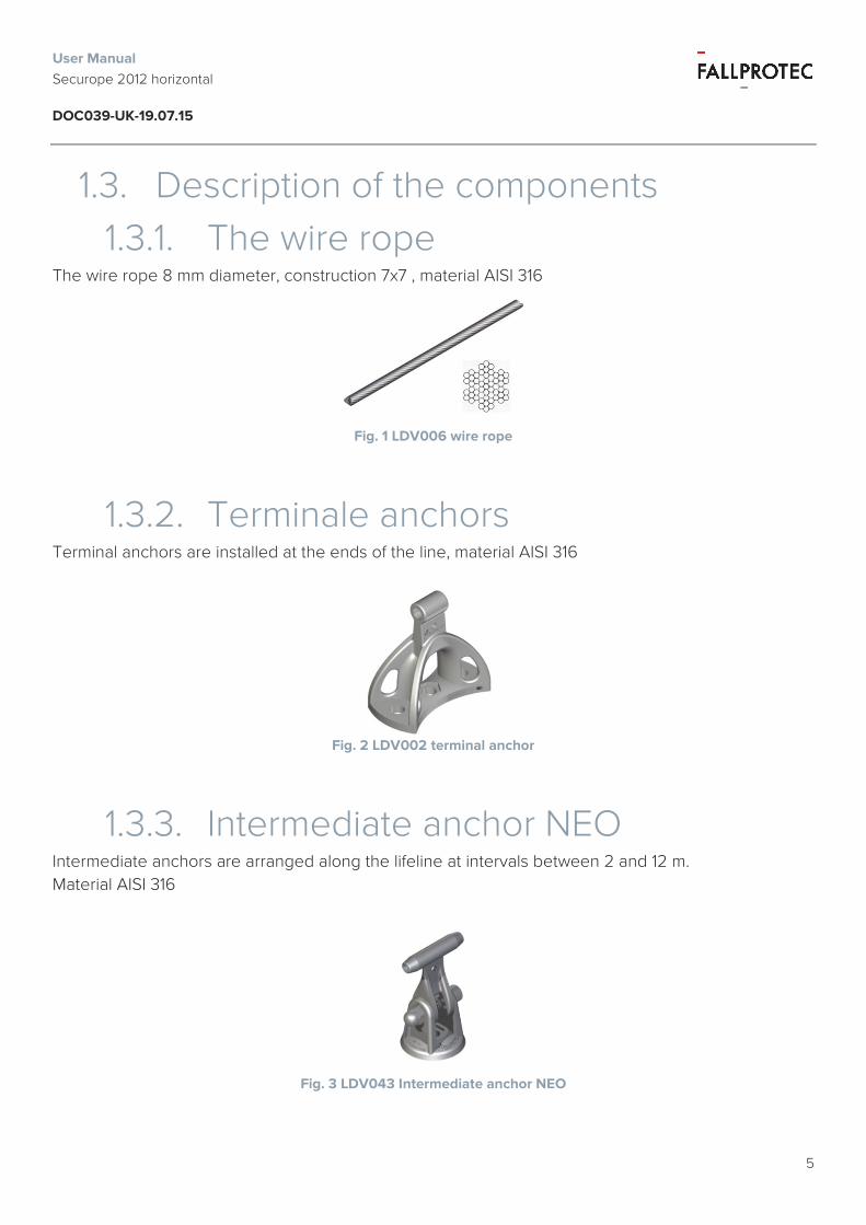
1.3. Description of the components 1.3.1. The wire rope
The wire rope 8 mm diameter, construction 7x7 , material AISI 316
Fig. 1 LDV006 wire rope
1.3.2. Terminale anchors Terminal anchors are installed at the ends of the line, material AISI 316
Fig. 2 LDV002 terminal anchor
1.3.3. Intermediate anchor NEO Intermediate anchors are arranged along the lifeline at intervals between 2 and 12 m. Material AISI 316
Fig. 3 LDV043 Intermediate anchor NEO

User Manual Securope 2012 horizontal DOC039-UK-19.07.15
6
1.3.4. Glider The glider allows the user to attach himself on the line. The glider may be placed and removed from the line. Material AISI 431.
Fig. 4 LDV001 Glider
1.3.5. Captive glider The captive glider is permanently attached to the line. Material AISI 316.
Fig. 5 LDV060 Captive glider
1.3.6. Energy absorber The energy absorber reduces the force which is transmitted to the building structure in case of a fall. An energy absorber is mandatory when the line is less than 20 m. Material polyurethane 95 shore.
Fig. 6 LDV032 Energy absorber

User Manual Securope 2012 horizontal DOC039-UK-19.07.15
7
1.3.7. Crimping ring 100mm The crimping ring serves as a stop for the line.
Fig. 7 LDV008 Crimping ring 100mm
1.3.8. Line tensioner The tensioner serves as a stop for the line and allows the tensioning of the line.
Fig. 8 The tensioner serves as a stop for the line and allows the tensioning of the line.
1.3.9. Crimping ring for junction The crimping ring for junction allows end to end attachment of the wire rope.
Fig. 9 Crimping ring for junction

User Manual Securope 2012 horizontal DOC039-UK-19.07.15
8
1.3.10. Turnbuckle The turnbuckle allows end to end attachment of the wire rope in case of a closed loop.
Fig. 10 LDV138 Turnbuckle
1.3.11. Cable guide for curve The cable guide for curve is used in conjunction with the corner plate and allows the tensioning of the cable from one of the ends of the line.
Fig. 11 LDV076 Cable guide for curve

User Manual Securope 2012 horizontal DOC039-UK-19.07.15
9
2. Marking 2.1. Warning plate
An identification plate is installed near to the zone where the users attach themselves to the line. Our web portal Fallprotec Assistant generates the plate. It can be printed on a sticker provided by Fallprotec (climate proof). The commissioning date must be on the warning plate.
Manufacturer informations and a QR code to get direct access to all the informations related to the installation Equipment type and applied standards. Logo and installer name Symbol indicating that it is mandatory to use a fallarrest harness according to EN355 Maximal number of users and their weights Information about the installation place. Commissioning date It is mandatory to read the user manual before use. The serial number of the self-locking tag
❾
The sticker will be fixed on a bendable plate. A self-locking Tag with a serial number has to be fixed on the plate
User Manual Securope 2012 horizontal DOC039-UK-19.07.15
10
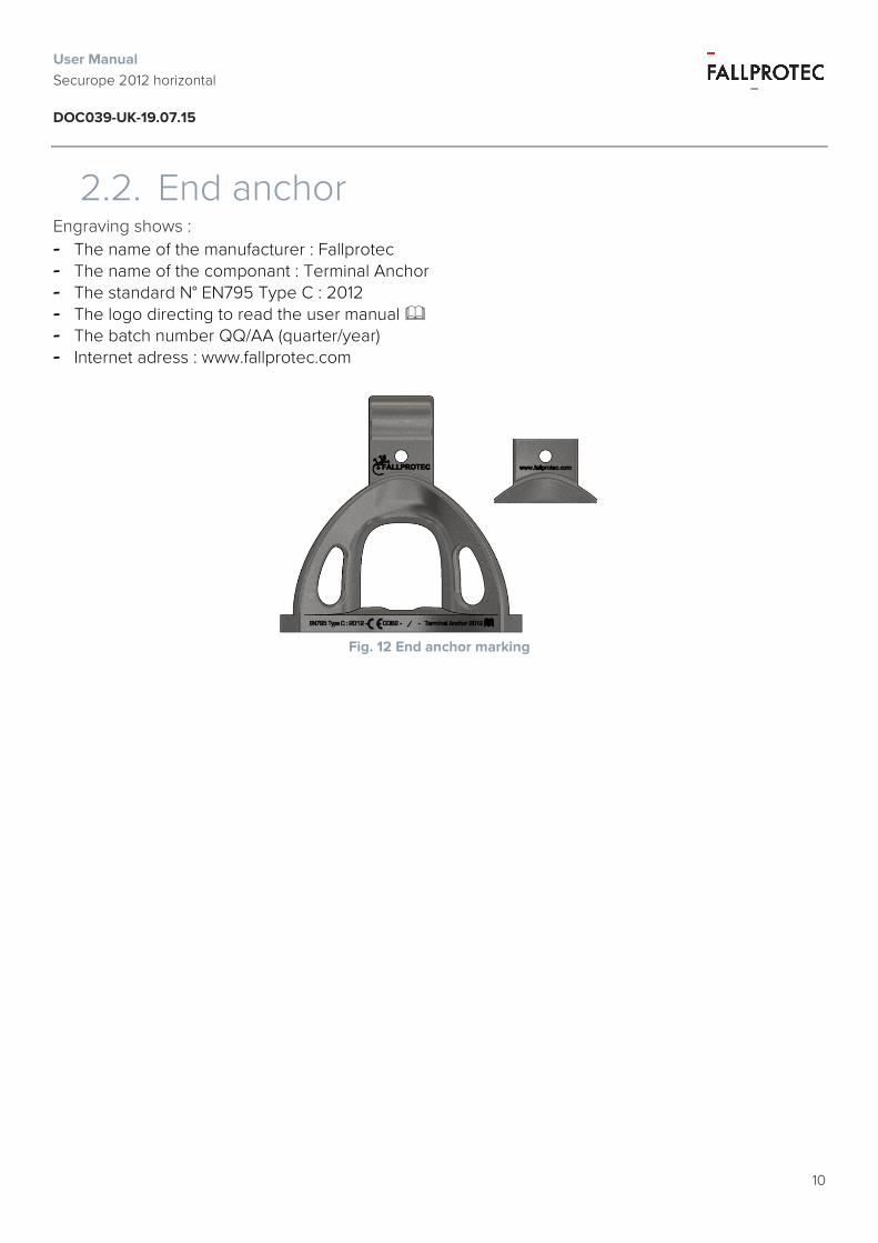
2.2. End anchor Engraving shows : - The name of the manufacturer : Fallprotec - The name of the componant : Terminal Anchor - The standard N° EN795 Type C : 2012 - The logo directing to read the user manual - The batch number QQ/AA (quarter/year) - Internet adress : www.fallprotec.com
Fig. 12 End anchor marking

User Manual Securope 2012 horizontal DOC039-UK-19.07.15
11
2.3. Intermediate anchor NEO Engraving shows : - The name of the manufacturer : Fallprotec - The name of the componant : Terminal Anchor - The standard N° EN795 Type C : 2012 - The logo directing to read the user manual - The batch number QQ/AA (quarter/year) - Internet adress : www.fallprotec.com
Fig. 13 LDV034 Intermediate anchor NEO marking
2.4. Glider Engraving shows : - The name of the manufacturer : Fallprotec - The batch number (month/year) - The standard N° EN795 Type C : 2012 - The CE mark The logo directing to read the user manual
Fig. 14 Glider marking

User Manual Securope 2012 horizontal DOC039-UK-19.07.15
12
2.5. Captive glider Engraving shows : - The name of the manufacturer : Fallprotec - The batch number (month/year) - The standard N° EN795 Type C : 2012 - The CE mark - The logo directing to read the user manual
Fig. 15 Captive glider marking
2.6. Energy absorber Engraving shows : - The name of the manufacturer : Fallprotec - The batch number (month/year)
Fig. 16 Energy absorber marking

User Manual Securope 2012 horizontal DOC039-UK-19.07.15
13
3. Homologation The Securope Life line Securope 2012 is an anchoring device in accordance with : - Standard EN795:2012 - type C - Standard CEN/TS16415 (4 users max) : Conformity certificate n°13.6.0803/A The Securope 2012 life line has been subjected to a CE type examination by the notify body APAVE SUDEUROPE SAS 8 rue Jean-Jacques Vernazza Z.A.C. Saumaty-Séon - BP 193 13322 MARSEILLE CEDEX 16
CE certificate: n°0082/1084/160/04/14/0116 du 18/04/2014 Notify body bearing the number: 0082 Notify body in charge of checking the production: 0082
4. Instruction for resale If the equipment is resold out of the first destination country, the reseller will provide instructions for maintenance, for periodic reviews and instructions on repairs, in the language of the country of use.
5. Skills of the installer The anchor device must be installed by competent persons or organizations that will have a certificate of “approved installer” issued by Fallprotec. The installation must be properly verified by calculation or testing. The installation will be carried out in conformity with the Securope Installer manual DOC023-UK
6. Installation of Securope The anchor device Securope is a horizontal lifeline system with a maximal inclination of 15°. The user must be able to access and exit safely. The installer must install the Securope lifeline so that the maximum angle at which the Securope cable is allowed to penetrate or exit of the intermediate anchor does not exceed 15°. The minimum clearance must be superior of the height of fall so that a falling user don’t hit an obstacle during the fall.

User Manual Securope 2012 horizontal DOC039-UK-19.07.15
14
The height of fall is the sum of the terms given below :
- DDeflection : the deflection of the rigid anchor line - HSafety : safety distance (1m) - Fall clearanceRequired : minimal height calculated and required in case of a fall - Fall clearanceAvailable : actual height available between the path and the first obstacle - LPath : distance from the rigid anchor line to the edge - LLanyard : lenght of the lanyard (< 2m) - LAbsorber : deployment of the energy absorption system (< 0,8m) - HUser : user’s height
Fall
clea
ranc
e Ava
ilabl
e
Fall clearanceRequired = DDeflection + LLanyard + LAbsorber - LPath + HUser + HSafety
Fall clearanceRequired < Fall clearanceAvailable

User Manual Securope 2012 horizontal DOC039-UK-19.07.15
15
If the height of fall is to large, Fallprotec advise mounting 20 mm crimping rings on both sides of each anchor means. The free length of cable can then be reduced to 5 times the distance between two successive anchors, see Fallprotec calculation software. The installer will write on the warning plate the maximum deflection of the wire rope in case of a fall. Fallprotec provides a software Securope V5.0 for the calculation of the deflection.
6.1. Structure on which the Securope is installed
A competent person will check the strength of the structure in relationship with forces transmitted by the end and intermediate anchors when a fall is stopped. Fallprotec makes software available, approved by the notify body, which works out the forces in accordance with the site configuration and the number of users. The components of the Securope line withstand without permanent deformation the forces indicated to table below and present a safety coefficient of two. The forces calculated by the software must be lower than the allowable forces. If you note a force beyond the allowable force it will be necessary to change one or more parameters of calculation, either to decrease the number of users or to decrease the distance between two anchors.
Component description Allowable force kN
Breaking strength kN
End anchor 18.5 50 Intermediate anchor LDV004/043/083
9 24
Cable 7x7 18.5 37 Crimping 18.5 37 Glider 6 50
Fig. 17 Table showing the allowable forces

User Manual Securope 2012 horizontal DOC039-UK-19.07.15
16
7. Personal protective equipment The Securope lifeline should be used in conjunction with height safety PPE in accordance with EN354, EN355, EN361, EN362. .
Fig. 18 HAR010 Longe simple avec absorbeur
Fig. 19 HAR018 / HAR013 Connecteur ½ tour
Fig. 20 HAR001 Harnais Prolight

User Manual Securope 2012 horizontal DOC039-UK-19.07.15
17
8. Recommendations relating to the documentation required after installation
New requirements of EN795:2012 For the user, the documentation on the installation provides evidence that the installation was performed correctly. In addition, it serves as an essential foundation for further examination of the anchor, because, in many cases, fixing anchors are not visible or accessible. After installation, the installer sends the user copies of the documentation for the installation. This documentation must be kept in the building for subsequent reviews of the anchor.
Documentation on the installation must contain at least the following information:
- The address and location of the installation; - The name and address of the company that carried out the installation; - The name of the person responsible for the installation; - The product identification (manufacturer of the anchor, type, model / item); - The fixing device (manufacturer, product, and transverse tensile forces eligible); - The schematic plan of the installation, for example the roof, and information relevant to the user, such as the position of the anchor points (for example relevant in case of snow).
Should be marked on the schematic plan of the building so that it is visible or available to all (for example, at the point of access to the roof).
The statements made by the responsible installer must be signed by him and attest that at least the anchor:
- Has been installed in accordance with manufacturer's installation instructions; - Is consistent with the plan; - Was attached to the specified support; - Has been set as specified (eg, number of bolts, correct materials, position / location correct); - Was put into service according to information supplied by the manufacturer; - Came with photographic information / documentation, especially when the fasteners (eg bolts) and the underlying support are no longer visible once installation is complete.
When several anchor points must be photographed for identification purposes, it is recommended to mark the anchoring devices with numbers and incorporate this numbering in the inspection records of the anchoring device and the ground plan in the installation area. Fallprotec provides the installer with a model for the "Installer schematic plan"

User Manual Securope 2012 horizontal DOC039-UK-19.07.15
18
Schematic plan of installation
Building / Structure Adress : Notes :
Order N°: Type of order : Shape of the roof : Anchoring device: Class C- Lifeline
Client Name : Adress :
Contact : Telephone N°:
Installer Name : Adress :
Installer chief: Telephone N°:
Anchoring device Manufacturer : FALLPROTEC Model identification /type : Securope 2012 Building components Attachments / Studs Data of fixations Ø drilled hole
Depth Torque
mm mm N.m
Type : Material : Minimum distance from the edge (c): Minimal axial distance (s): Minimum thickness of the component: Permissible tensile strength : Breaking force :
Distance from the edge Axial spacing
Cx: Sx:
Cy: Sy:
Notes: Drilling method: Test device:
Hammer Rotative Wrench
Cleaning of the drilled hole Testing devise of fixations
System impact
yes Humid yes
No dry No
Control list Ground plan of the roof: Substrate except exceptions (no doubt on the capacity) Installation in accordance with manufacturer’s instructions Recommended attachments used All attachements photographed with identification Visibles attachments Installation plan attached on site Screw immobilisation by traversing fixing technique Additional information
Breakout force (kN), required torque (Nm) Anchoring point 1 Anchoring point 2 Anchoring point 3 Anchoring point 4
Anchoring point 5 Anchoring point 6 Anchoring point 7 Anchoring point 8
Anchoring point 9 Anchoring point 10 Anchoring point 11 Anchoring point 12
Anchoring point 13 Anchoring point 14 Anchoring point 15 Anchoring point 16
Adittional fixations: Note of installation chief:
Date : Signature

User Manual Securope 2012 horizontal DOC039-UK-19.07.15
19
9. User manual 9.1. Preliminary check
The following checks are mandatory before using the SecuRope Lifeline. o The user of the lifeline must be in good physical condition, and not prone vertigo or giddiness. o The user must have received adequate training for the following
o Use of the fall protection equipment, o Working with the SecuRope lifeline, o Use of the rescue equipment in the event of fall.
o A minimum of two people is required to work together on the lifeline, so that each can assist the other in the event of an incident.
o A rescue plan must be in place to evacuate the person who fell within 15 minutes. The rescue material must be easily accessible and be located in the vicinity from the lifeline.
o No more than four people may be connected to the cable at the same time; however, the manufacturer’s label clearly states the maximum number of people who may be connected to the lifeline simultaneously, namely 1, 2, 3 or 4 persons.
o Each user must be equipped with : o A suitable harness with two anchoring points, one at the back and one at the chest , in
conformity with the EN 361 standard, o The chest anchor point is the preferred point for anchoring the harness, the dorsal
anchoring point being used for rescue operations. o An energy absorber lanyard in conformity with EN 354/355 standard. o Two karabiners twist lock type in zinc plated steel, according to EN 362 and having the
following characteristics, length 105 mm, width 58 mm, wire diameter 10 mm, opening 20 mm, breaking strength 23 kn.
o On arrival in the work area, or whenever the user attaches to the cable, he is required to check :
o That the manufacturer’s label is in place, and that it mentions the maximum number of users who can connect to the lifeline simultaneously
o That the fall indicator has not been activated. o That the glider, the harness and the lanyard are in good, working condition o That there is no obstruction under the walk way that could reduce the clearance
specified on the manufacturer’s label o The system must be immediately put out of service if the user notes one or more
anomalies to the points indicated above. o Checking the Fall Indicator
o The fall indicator is installed on the end anchor equipped with an energy absorber. The user can normally reach the side of the final anchor.
o The indicator is a spherical steel part, which rests on an elastic seat. o In the event of fall, the spherical part penetrates into the elastic seat. o If the user sees that the sphere is no longer visible, he must inform a qualified person
of the situation before using the line.

User Manual Securope 2012 horizontal DOC039-UK-19.07.15
20
Fig. 21 Fall indicator not activated Fig. 22 Fall indicator activated
9.1.1. Attach to the cable The user attaches to the cable in an area where there is no risk of falling, in principle in the vicinity of one of the two end anchors. The user must use a mobile anchor point (hereinafter referred to glider) and the associated connector.
9.1.2. Use of the glider LDV001 The glider is attached to the cable side to the user see Fig. 38
Fig. 23 Correct orientation of the glider
To connect the glider, the user tilts the glider, opens the locking device and fits the glider over the cable - see Fig.7-8-9.
Fig. 24 Locking device open Fig. 25 Locking device closed Fig. 26 Karabiner on the glider

User Manual Securope 2012 horizontal DOC039-UK-19.07.15
21
Once locking device is closed again under the action of the spring, the user is connected to the glider with a karabiner delivered with the glider. An energy absorber lanyard connects the glider to the harness. To disconnect from the line, the user must first detach the karabiner of the glider and then open the locking device. In the event that the user moves on both sides of the lifeline, for example in the case of a line installed along a pitch roof, he will have to undo the glider and re-orientate it before reconnecting to the cable whenever he needs to move from one side of the cable to the other.
9.1.3. Circulating along the lifeline The user pulls on the glider via the lanyard to allow the glider to pass the intermediate anchors without jolting.
Fig. 27 Glider attached to the cable
9.1.4. Use of a fall arrest block attached to the line
The Securope Lifeline may be used in conjunction with a fall arrest block, IHW range distributed by Fallprotec.
9.1.5. Warning • It is essential for safety that the device is always correctly positioned and that the work is
carried out so as to minimize the risk of fall and fall height. • The weight of the user, including his equipment must not exceed 120 kg. • The user will ensure that he is kept safe before detaching the glider. • The lifeline Securope should not be used as a work positioning system.

User Manual Securope 2012 horizontal DOC039-UK-19.07.15
22
9.1.6. Prohibited use • Only one user working at height, but without the support of a second person able to provide
assistance if needed. • More than four persons attached to the lifeline simultaneously. • the fall indicator is no longer visible, it has been pulled into the cylinder. • An obstacle under the walk way which reduces the clearance specified on the manufacturer’s
label • Deposits of ice on the cable and the anchors. • Temperatures lower than -30 °C • It is strictly prohibited to use the lifeline outside the limits specified in this document or outside
any other situation for which it is designed. • The length of the lanyard absorber is limited to 2 meters, except where there is a written
statement to the contrary from the manufacturer for a specific project. • It is forbidden to use any another karabiner to attach the lanyard to the glider that provided by
Fallprotec. The function of safety of the glider could be affected if the karabiner used is not the karabiner supplied by FALLPROTEC.
9.1.7. Instructions for storage and maintenance
• The glider must be stored in a place away from moisture. • The SecuRope lifeline must be inspected by a qualified person at least once a year, as well as
after every fall. • The safety of the users depends on the maintenance of the effectiveness and the resistance
of the equipment. • Reconditioning of the line after a fall requires a re-tensioning of the cable using FALLPROTEC
tools, as well as the repositioning of the guide cables on their support brackets. This work must be carried out by a qualified person who has received an adequate training by FALLPROTEC, and is in the possession of the Installer manual.
• The lubrication of the cable is recommended once a year in order to facilitate the movement of the glider. This recommendation is applicable only in an environment or installation where the lifeline can accept oil lubrication.
• Any modification of or addition to equipment can only be carried out after the prior written agreement of FALLPROTEC.
• If the equipment may be in contact with chemical, please contact Fallprotec and tell us the exact name of the chemical concerned.
• The correct tightening of bolts and nuts should be checked. • Check that the turnbuckle LDV038 is not released, tighten and lock it with Loctite

User Manual Securope 2012 horizontal DOC039-UK-19.07.15
23
9.1.8. Operational life of the installation • All the components of the lifeline are manufactured from of stainless steel according to the
AISI 316 / 431 / 304 , which have a great resistance to the atmospheric degradation.
• The operational life is a function of the building structure and of its capacity to maintain its physical properties in the course of time.
• The operational life of the Securope lifeline is limited to 20 years.

User Manual Securope 2012 horizontal DOC039-UK-19.07.15
24
10. Recommandations relating of periodic review procedure
Periodic review of anchoring devices
Document relating to the available
installation
Visual review and functional test
Controls of corrosion, deformation, cracking, loosened components,
the absence of labeling
Results of the control
Replacement of anchoring deviee
Documentation relating to the
installation
Marking and documentation relating to the review
Manufacturer identified?
visible Fixation No visible Fixation
Review in accordance with the construction technical
regulations of manufacturer regarding the type of load, type of fixing and mounting
structure .
Review in accordance with the information supplied by
manufacturer of type of test (for example visual review and functional test, static test or
dynamic test
Result of review Replacement of
anchoring deviee
Documentation relating to the installation
Unacceptable condition
Acceptable condition
YES NO
YES NON
Unacceptable or impossible
review
Acceptable

User Manual Securope 2012 horizontal DOC039-UK-19.07.15
25
Identification card of Securope Lifeline Type the equipment: Securope2012 lifeline Manufacturer : FALLPROTEC SA. 43-45, ZA Op Zaemer L- 4959 Bascharage Luxembourg Fax : +352 26 55 09 30 55 Email : [email protected] www.fallprotec.com
Equipment Identification:
Date of manufacturing:
Purchase date:
First use date:
Periodicity of inspection: Once a year
Estimated life time: 20 years.
Date of 1st review
Type of review & repairs Name and signature of competent person
Date of the next review
After 1 year of use
Visual
Cleaning of the Securope lifeline
Verification of energy absorbers
Verification of intermediate anchors, cable guide in the correct position.
Periodicity once a year
Check that the turnbuckle LDV038 is not released, tighten and lock it with Loctite
The correct tightening of bolts and nuts is checked.
Dates Defects noticed– relevant information Name and signature Prevision dates
NOTE: It is the responsibility for the user to provide the identification card and to fill it out with all details.