user manual - support...
TRANSCRIPT

User Manual

2
4-inch Color Changer (Model #4540)7-inch Color Changer (Model #7140)Software version: FR22, FR23, FR26Manual revision: June 2006
CONTENTSDeclarations of Conformity.........................................3Safety Information......................................................5Introduction................................................................9The Forerunner System .............................................9Using the Forerunner ...............................................10The Forerunner components....................................10
Color changer.............................................. .... .10Gelstring...................................................... .... .11Power supply............................................... .... .11Cables ......................................................... .... .12
Installing The Forerunner.........................................12Mounting and installation accessories......................14
Power supply hanger bracket ...................... .... .15Color changer mounting plate...................... .... .15
Replacing a gelstring ...............................................16Specifications...........................................................19Parts list...................................................................21Warranty information................................................22Gelstring order form.................................................23

3

4
Safety Information
SAVE THESE INSTRUCTIONSREAD AND FOLLOW ALL INSTRUCTIONS
This manual gives step-by-step instructions for the preparation, setup, and operation ofthe Forerunner Color Changer.
There is a potential risk of fire, electric shock or injury to persons if the product is notused as instructed.
WARNING: When using electrical appliances, use basic precautions, including:
• Read this manual before connecting power.• Use supervision around children.• Do not touch moving parts.• Only use attachments recommended or sold by Wybron.• Use in a dry location only.
The Forerunner Color Changer is to be used in an indoor environment only and is notintended for residential use.
For continued protection against risk of fire, replace only with same type and rating offuse.
Protection against electric shock is assured only if the mains connected power supplycord set is connected to a properly earthed grounding type receptacle.
An all pole disconnect device must be located adjacent to the unit or, if the AC cord isused as the main disconnect device, ensure that the socket-outlet is located/installednear the equipment and is easily accessible.
THE MAINS LEADS ARE COLORED IN ACCORDANCE WITH THE FOLLOWINGCODE AND MUST BE CONNECTED IN THE FOLLOWING SCHEME:- GREEN AND YELLOW: EARTH- BLUE: NEUTRAL- BROWN: LINEWARNING: THIS EQUIPMENT MUST BE EARTHED.
For questions, contact Wybron at 1-800-624-0146 or visit www.wybron.com.
Product Modification WarningWybron, Inc. products are designed and manufactured to meet the requirements ofUnited States and International safety standards. Modifications to the products couldaffect safety and render the product non-compliant to relevant safety standards.
5
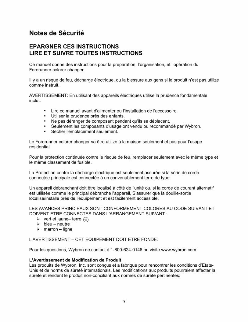
Notes de Sécurité
EPARGNER CES INSTRUCTIONSLIRE ET SUIVRE TOUTES INSTRUCTIONS
Ce manuel donne des instructions pour la preparation, l’organisation, et l’opération duForerunner colorer changer.
Il y a un risqué de feu, décharge électrique, ou la blessure aux gens si le produit n’est pas utilizecomme instruit.
AVERTISSEMENT: En utilisant des appareils électriques utilise la prudence fondamentaleinclut:
• Lire ce manuel avant d'alimenter ou l'installation de l'accessoire.• Utiliser la prudence près des enfants.• Ne pas déranger de composant pendant qu'ils se déplacent.• Seulement les composants d'usage ont vendu ou recommandé par Wybron.• Sécher l'emplacement seulement.
Le Forerunner colorer changer va être utilize à la maison seulement et pas pour l’usageresidential.
Pour la protection continuée contre le risque de feu, remplacer seulement avec le même type etle même classement de fusible.
La Protection contre la décharge électrique est seulement assurée si la série de cordeconnectée principale est connectée à un convenablement terre de type.
Un appareil débranchant doit être localisé à côté de l'unité ou, si la corde de courant alternatifest utilisée comme le principal débranche l'appareil, S'assurer que la douille-sortielocalise/installé près de l'équipement et est facilement accessible.
LES AVANCES PRINCIPAUX SONT CONFORMEMENT COLORES AU CODE SUIVANT ETDOIVENT ETRE CONNECTES DANS L'ARRANGEMENT SUIVANT :
vert et jaune– terre bleu – neutre marron – ligne
L'AVERTISSEMENT – CET EQUIPEMENT DOIT ETRE FONDE.
Pour les questions, Wybron de contact à 1-800-624-0146 ou visite www.wybron.com.
L’Avertissement de Modification de ProduitLes produits de Wybron, Inc. sont conçus et a fabriqué pour rencontrer les conditions d’Etats-Unis et de norms de sûreté internationals. Les modifications aux produits pourraient affecter lasûreté et rendent le produit non-conciliant aux normes de sûreté pertinentes.

6
Aviso Sobre Seguridad
SALVE ESTAS INSTRUCCIONESLEA Y SIGA TODAS INSTRUCCIONES
Este manual da el paso por paso las instrucciones para la preparación, para arreglo, y para laoperación del Forerunner colore rollo.
Hay un riesgo potencial del fuego, el calambre o la herida a personas si el producto no se utilizacomo instruido.
ADVERTENCIA: Cuando se usa electrodomésticos, el uso las precauciones básicas,incluyendo:
• Lea este manual antes de accionar o instalar la instalación fija.• Supervise a niños cercano.• No toque los componentes mientras ellos mueven.• Sólo utilice con componentes vendido o recomendado por Wybron.• Seque ubicación sólo.
El Forerunner colore rollo deberá ser utilizado en un ambiente interior sólo y no es pensadopara el uso residencial.
Para la protección continuada contra el riesgo del fuego, reemplaza sólo con mismo tipo ycalificación de fusible.
La Protección contra calambre se asegura sólo si el conjunto conectado principal de cuerda esconectado a un apropiadamente earthed que muele receptáculo de tipo.
Una toda asta desconecta dispositivo se debe localizar adyacente a la unidad o, si la cuerda deC.A. se utiliza como el principal desconecta dispositivo, asegure que la enchufe-salidalocaliza/instalado cerca del equipo y sea fácilmente accesible
EL PRINCIPAL DIRIGE SON COLORADOS DE ACUERDO CON EL CODIGO SIGUIENTE Yse DEBE CONECTAR EN EL ESQUEMA SIGUIENTE:
verde y amarillo – molió/la tierra azul – neutral brown – línea
La ADVERTENCIA – ESTE EQUIPO DEBE SER EARTHED.
Para preguntas, el contacto Wybron en 1-800-624-0146 o visita www.wybron.com.
Advertencia de Modificación de ProductoWybron, los productos S.a. se diseñan y son fabricados para encontrar los requisitos deEstados Unidos y estándares Internacionales de seguridad. Las modificaciones a los productospodrían afectar la seguridad y rendir el producto no conformista a estándares pertinentes deseguridad.

7
Sicherheitshinweise
BEHALTEN SIE DIESEN ANWEISUNGENLESEN SIE UND GEHORCHEN SIE ALLEN ANWEISUNGEN
Dieses Handbuch gibt Schritt für Schritt Anweisungen zur Vorbereitung, Aufstellung, undFunktion dem Forerunner.
Es gibt ein potenzielles Risiko des Feuers, Elektroschocks oder Verletzung zu Personen, wenndas Produkt nicht benutzt ist, als unterrichtet ist.
WARNUNG: Beim Benutzen elektrischer Geräte, Gebrauch grundlegendeVorsichtsmaßnahmen, einschließlich:
• Lesen Sie dieses Handbuch vor Betreiben oder Installieren des Inventar.• Benutzen Sie Aufsicht nahe Kinder.• Berühren Sie Bauteile nicht, während sie bewegen.• Nur Gebrauch mit Bauteilen verkauft oder hat durch Wybron empfohlen.• Trocken Sie Ort nur.
Der Forerunner soll in einer Hallenumwelt nur benutzt werden und ist für Heimumwelt nichtvorgehabt.
Für fortgesetzten Schutz gegen Risiko des Feuers, ersetzt nur mit gleichem Typ und Bewertungder Sicherung.
Schutz gegen Elektroschock ist nur gezusichert, wenn die Hauptleitungen Schnursatzverbunden haben, ist an eine ordentlich earthed Erdung von Behälter angeschlossen.
Eine alle Stange schaltet Vorrichtung muss sich befunden werden neben der Einheit ab oder,Wenn die AC Schnur benutzt ist, während die Hauptleitung Vorrichtung abschaltet, Sichert,dass der Steckdosensteckdose ist befunden/nahe die Ausrüstungen installieren, und ist leichtzugänglich.
DIE HAUPTLEITUNGEN BLEIE SIND GEMÄSS DEM FOLGENDEN CODE GEFÄRBT UNDMÜSSEN IM FOLGENDEN SCHEMA VERBUNDEN WERDEN:
Grün und Gelb – Erden Sie/Erde Blau – neutral Braun – linie
WARNUNG – DIESE AUSRÜSTUNGEN MUSS EARTHED WERDEN.
Für Fragen Kontakt Wybron an 1-800-624-0146 oder besucht www.wybron.com.
ProduktänderungswarnungWybron, Inc. Produkte sind entworfen und sind hergestellt, die Voraussetzungen vonVereinigten Staaten und Internationalen Sicherheitsstandards zu erfüllen. Änderungen zu denProdukten könnten Sicherheit beeinflussen und könnten das Produkt leisten dasverordnungswidrig ist zu relevanten Sicherheitsstandards.

8
Introduction
The Forerunner system is a scrolling color changer, available in 4-inch and7-inch models, and a power supply offering ease of setup and use. Its 16-color capacityand DMX compatibility affords the designer economy and versatility, particularly whenbudget and space are limited. The lightweight color changers slide easily into the gelframe holder of the light fixture and the compact PS Power Supply attaches easily to thetruss of the lighting rig.
This manual gives step-by-step instructions for preparation, setup and operation of theForerunner Color Changer.
The Forerunner System
The Forerunner System consists of one or more color changers and a remote powersupply which can power up to 64 color changers. The DMX512 control signal from thelighting board is connected to the power supply and can continue onto more PS PowerSupplies or other DMX-controlled devices. The power supply sends both power andcontrol signal on a single cable eliminating the need for a separate power cable for eachcolor changer.
Caution: The Forerunner System is not compatible with the Coloram II/RAMSystem. Do not connect Coloram II Color Changers to PS Power Supplies, orForerunner Color Changers to Coloram II (RAM) Power Supplies. Damage fromsuch action will not be covered by the Forerunner or Coloram II warranties.
PS-150 Power Supply Forerunner Color Changer
AC PowerTo additional ForerunnerColor Changers
To additional PSPower Supplies
To additional ForerunnerColor Changers
DMX512
DMX512Control
BufferedDMX512

9
Using The Forerunner
The Forerunner Color Changer sets its frame position according to the DMX512 level itreceives from the control console for the channel it is set to. The following chart showsthe level settings that correspond with each frame position. The color of each frameposition will be determined by your custom gelstring specification.
ChannelLevel
FramePosition
00 Frame 107 Frame 214 Frame 321 Frame 428 Frame 534 Frame 642 Frame 748 Frame 855 Frame 961 Frame 1068 Frame 1175 Frame 1280 Frame 1388 Frame 1494 Frame 15FL Frame 16
If you send a channel level that is between the values shown, you can create split frameeffects. For example, if you send a level of 51, the color changer positions the gelstringhalfway between frame 8 and frame 9 creating a blend of the two colors.
The Forerunner Components
Color Changer
The Forerunner Color Changer works with a 16-frame gelstring. The position of thegelstring is controlled by DMX signal distributed from the power supply. The colorchanger is powered by 24 volts DC from the power supply. The control signal and DCpower are both supplied in the one cable connecting the color changer to the powersupply.

10
Gelstring
The gelstring is a series of 16 precisely-cut, colored gel frames joined together, side byside, to create a sequence of colors. Two additional gels at each end of the gelstring arecalled the leader and the trailer and are five inches wide to allow for proper attachmentto the rollers.
If you need to replace a gelstring in your color changer, detailed steps for this procedureare on page 16.
Power Supply
Note: As of June 2006 the Forerunner ships with a PS-150, PS-300 or PS-600 PowerSupply, however, Forerunner will still operate with Forerunner Power Supplies.
The power supply has two color changer outputs and provides each color changer withDMX signal and 24 volts DC. The power supply features a DMX bypass relay to passthe DMX signal to the DMX output connector in the event of AC power loss. AC poweris indicated by a red LED which can be viewed from the stage.
LeaderFrame 1Frame 2Frame 15Frame 16Trailer
Figure 3
4-inch Forerunner 7-inch Forerunner

11
Cables
The Forerunner cable connects each of the two power supply outputs to a daisy chainof up to eight Forerunner Color Changers and provides the color changers with powerand control signal. The Forerunner cable uses 4-pin XLR connectors on either end andconsists of two -14 AWG conductors and a 22 AWG twisted, shielded pair.
Note: The cable used in the Forerunner System is the same cable which is used in theRAM/Coloram II System and may be referred to as either RAM/Coloram II cable orForerunner cable.
Installing the Forerunner
To get your Forerunner System up and running, follow these hookup and checkoutprocedures.
1. Set the DMX512 color changer channels
Each color changer is assigned an individual DMX address to which it will respond fromthe lighting console. The addresses are set via the three rotary switches located on theback of each color changer. Valid DMX addresses are 001 - 512.
12
2. Attach the color changer to the fixture
Slide the color changer's mounting bracket into the gel frame holder of your fixture andlock the gel frame retention clip (if available).
If the mounting plate installed on your color changer doesn't fit the fixture, you mayreplace it with a differently sized plate. See page 15 for information on changingmounting plates.
The mounting plate allows you to position the color changer with the gelstring rollingeither horizontally or vertically. However, Forerunner operates most effectively with thefan blowing air vertically (as hot air naturally rises).
3. Attach the safety cable
A safety cable is attached to the back, right hand side of the color changer. Run thiscable around the pipe or truss from which you hang the light fixture and clip it to itself(fig. 5).
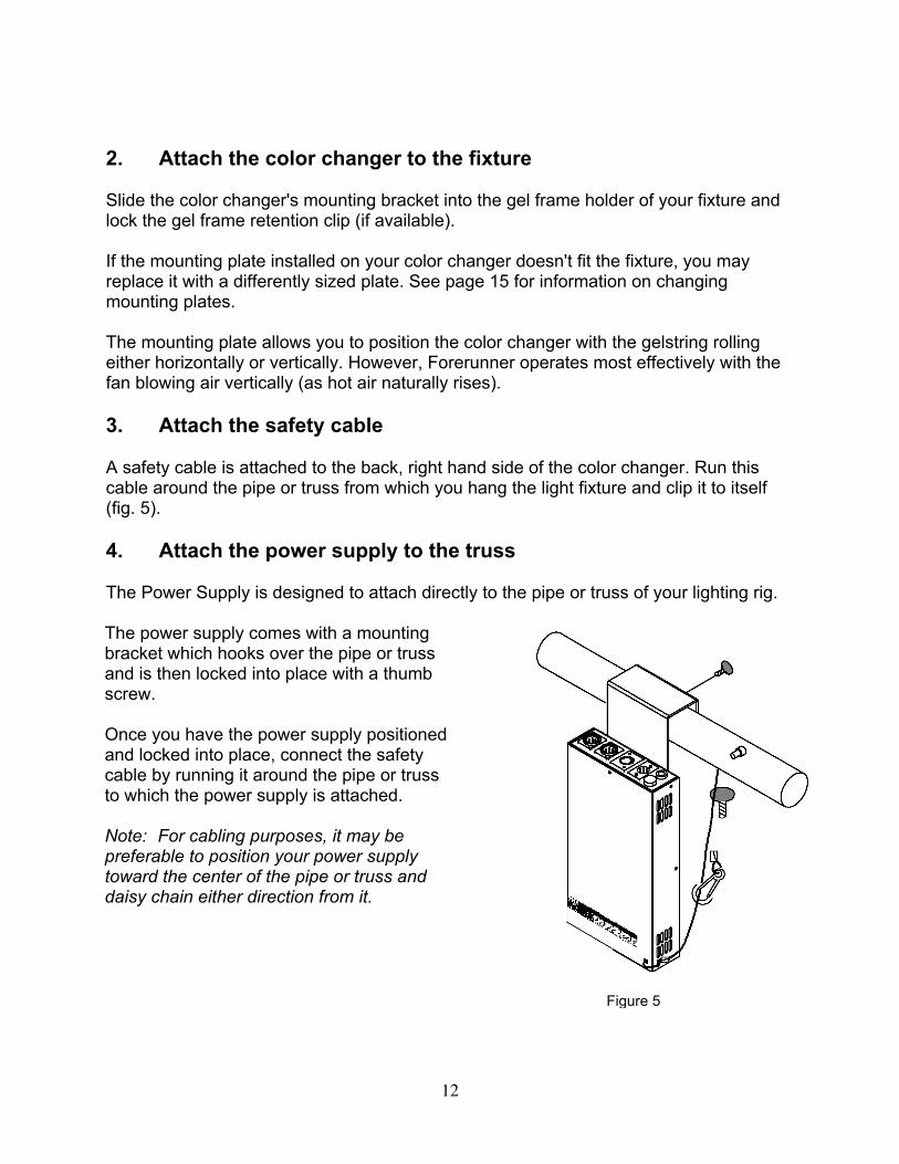
4. Attach the power supply to the truss
The Power Supply is designed to attach directly to the pipe or truss of your lighting rig.
The power supply comes with a mountingbracket which hooks over the pipe or trussand is then locked into place with a thumbscrew.
Once you have the power supply positionedand locked into place, connect the safetycable by running it around the pipe or trussto which the power supply is attached.
Note: For cabling purposes, it may bepreferable to position your power supplytoward the center of the pipe or truss anddaisy chain either direction from it.
Figure 5

13
5. Connect the color changers to the power supply
Connect the color changers to the power supply using the supplied 4-pin power/signalcable. The connectors are on the back of the color changers and the front of the powersupply.
Note: Both power and signal are supplied to the color changers on the same cable. Thepower supply has two color changer outputs. Each output will control up to eight colorchangers with a maximum of 350 feet of cable per output.
6. Connect the power supply to AC power
Plug the AC cord into a non-dimmed power circuit.Input voltage: 100-240V~50/60Hz 3-1.5AFuse: 250V 2A SloBlo for 100-120V~
250V 1A SloBlo for 220-240V~
Power at the power supply is indicated by a red LED which can be viewed from thestage. Power is also indicated by a red LED on the bottom of each color changer. Allconnected color changers will position their gelstrings to frame 1.
Caution: Do not power the power supply from a dimmer. Severe damage willresult, and is not covered by product warranty.
7. Connect and set the DMX512 source
Connect the DMX512 signal source to the DMX input connector on the front of thepower supply using standard DMX cable. Valid DMX signal will be indicated by a greenLED on the bottom of each color changer. Also, the color changers will now positiontheir gelstrings according to their respective DMX signal levels.
Mounting and installation accessories
The components of your Forerunner System may require the installation of additionalmounting accessories or the replacement of others. Some of these accessories, suchas the power supply hanger bracket and your choice of one color changer mountingplate, are supplied while other accessories, such as additional mounting plates, mayneed to be purchased separately. The following sections describe the procedures forinstallation and replacement of these accessories

14
Power supply hanger bracket
The PS Power Supply is shipped with a hanger bracket to allow pipe or truss mounting.The hanger bracket will need to be installed prior to the Forerunner System installation.
Follow these steps to install the hanger bracket.
1. Disconnect AC power from the power supply.
2. Place the power supply upside down on a flat surface.
3. Position the bracket as shown below.
4. Attach the bracket using a 3/16" Allen wrench and the supplied screws.
Note: Use the supplied thumb screw to clamp the hanger bracket to the desired pipe ortruss.
Color changer mounting plate
The Forerunner Color Changer ships with your choice of available mounting platesinstalled. It may be necessary, when mounting the color changer on different lightfixtures, to replace the mounting plate.
Follow these instructions to replace the mounting plate.
1. Place the color changer on a flat surface, with The Forerunner logo face down.
2. Unscrew the four screws which hold the current mounting plate on.
3. Place the replacement mounting plate on the color changer, aligning the screwholes properly.
4. Fasten the four corners of the mounting plate to the color changer
Figure 6

15
using the same screws you removed in step 2.
Note: Always use the supplied screws, as they are treated with an anti-vibrationcompound to keep them from loosening.
Replacing a gelstring
At some point in time you may find that you need to replace the gelstring in your colorchanger, either because the old one wears out, or because you want a differentselection of colors. The Forerunner's AutoloadTM feature makes this quick and easy.
Caution: Operating the Forerunner Color Changers with damagedgelstrings will damage the color changers. Replace the gelstrings beforedamage occurs.
Note: The gelstring must be 16 frames long for proper operation. If a frame isdamaged, do not remove a frame and splice the gelstring. Replace the gelstring.Gelstrings may be ordered from ColorExpress by WYBRON. Call 1-800-624-0146.
Mounting plate
Mounting plate screws Figure 7

16
Caution: Do not force the rollers to turn when moving them by hand. Ifthey do not turn easily, you have not disconnected the color changer fromthe power supply and should do so immediately.
Remove the old gelstring
This procedure is performed with no power to the color changer.
1. Place the color changer on a flat surface with the Forerunner logo facing up.
2. Remove the front panel by unscrewing the two thumb screws at the top right and left corners of the front door as shown in the first picture on the left.
3. Gently roll the gelstring onto the left roller, exposing the clear leader taped on the right roller.
4. Untape the leader from the right roller. Remove the tape from the leader.
5. Roll the gelstring into a tube, slowly rolling it off of the left roller.
6. When you reach the clear trailer, untape it from the roller.
Hint: To save time, move all gelstrings to frame one via the DMX source before disconnecting power.
Install the new gelstring
Note: Use gaffer's tape to attach the gelstrings to the rollers. Do not use duct tape ormasking tape.
Thumb screws
LOAD GELADJUST GEL
Figure 8
Right roller(Trailer/frame 16)
Left roller(Leader/frame 1)

17
1. Apply power to the color changer.
2. Press the recessed "Load Gel" button located in the lower right hand corner of the color changer. The rollers will rotate to the trailer load position. The rapidly flashing "DMX" LED indicates the rollers are either moving toward the trailer load position or are at the trailer load position. 3. Put a strip of gaffer's tape on the edge of the gelstring trailer. Holding the trailer, let the rest of the roll hang off the right side of the color changer.
4. Center the edge of the trailer between the two ends of the left roller as shown to the left. Tape the trailer along the top
of the roller as shown.
5. Hold the gelstring loosely in your right hand and press the "Load Gel" button again. The rollers will rotate to the leader load position. This will wind the gelstring onto the left roller. The "DMX" LED will flash slowly to indicate the rollers are either moving toward the leader load position or are at the leader load position. 6. Turn the "Adjust Gel" trim pot to bring the leader end of the gelstring to the top center of the right roller. Gel material of different thickness will cause variation in the leader end position. This is normal.
7. Put a strip of gaffer's tape on the gelstring leader.
8. While holding the end of the gelstring, turn the spring roller 3.5 turns toward thedrive roller. The sticker at the bottom end of the roller has a black line on it tohelp you judge the number of turns
9. Tape the gelstring to the spring roller.
10. Press the "Load Gel" button once again. The gelstring will now move to the first
frame if no DMX signal is present or to the commanded DMX level if it is.
11. Replace the front panel and tighten the thumb screws securely.
Note: As the gelstring becomes worn, you may find it necessary to adjust the positionof frame 1. This is normal and is done by turning the "Adjust Gel" trim pot.
Figure 11
Gaffer’s tape
Frame 16
Frame 16
Trailer

18
Specifications
Forerunner Color Changer (Model #4540 and #7140)
Operating voltage: 24V @ 0.3ADMX termination: Not requiredEnd to end speed: 5 secondsFan: Single speedGelstring: 16 colorsIndividual DMX address: 001 - 512Fixture compatibility (with optional mounting plates):
4-inch Forerunner--Source Four--Shakespeare 600--Other fixtures with 6.25" gel frames
7-inch Forerunner--Source Four--Shakespeare 600--Other fixtures with 6.25" gel frames--Source Four PAR--PAR 64--Full size ellipsoidals
LED Indicators: Power and DMX512 signalPower supply compatibility:
--Forerunner Power Supply--Rainbow Power Supply--ChromaQ Power Supply
Weight: 4-inch - 3.44 lbs./1.56 kg7-inch - 3.92 lbs./1.77 kgPower Supply - 4.28 lbs./1.94 kg
Forerunner gelstring
4-inch Forerunner: --Frame width: 8"--16 frames plus leader and trailer --Frame height: 6 1/8"--Working length: 128" --Leader: 5"--Overall length: 138" --Trailer: 5"
7-inch Forerunner: --Frame width: 10"--16 frames plus leader and trailer --Frame height: 7 1/16"--Working length: 160" --Leader: 5"--Overall length: 170" --Trailer: 5"
19
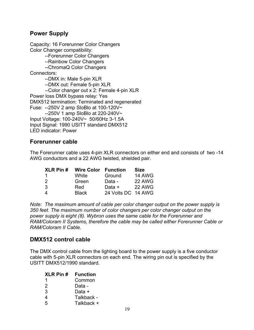
Power Supply
Capacity: 16 Forerunner Color ChangersColor Changer compatibility:
--Forerunner Color Changers--Rainbow Color Changers--ChromaQ Color Changers
Connectors: --DMX in: Male 5-pin XLR--DMX out: Female 5-pin XLR--Color changer out x 2: Female 4-pin XLR
Power loss DMX bypass relay: YesDMX512 termination: Terminated and regeneratedFuse: --250V 2 amp SloBlo at 100-120V~
--250V 1 amp SloBlo at 220-240V~Input Voltage: 100-240V~ 50/60Hz 3-1.5AInput Signal: 1990 USITT standard DMX512LED indicator: Power
Forerunner cable
The Forerunner cable uses 4-pin XLR connectors on either end and consists of two -14AWG conductors and a 22 AWG twisted, shielded pair.
XLR Pin # Wire Color Function Size1 White Ground 14 AWG2 Green Data - 22 AWG3 Red Data + 22 AWG4 Black 24 Volts DC 14 AWG
Note: The maximum amount of cable per color changer output on the power supply is350 feet. The maximum number of color changers per color changer output on thepower supply is eight (8). Wybron uses the same cable for the Forerunner andRAM/Coloram II Systems, therefore the cable may be called either Forerunner Cable orRAM/Coloram II Cable.
DMX512 control cable
The DMX control cable from the lighting board to the power supply is a five conductorcable with 5-pin XLR connectors on each end. The wiring pin out is specified by theUSITT DMX512/1990 standard.
XLR Pin # Function1 Common2 Data -3 Data +4 Talkback -5 Talkback +

20
Parts list
To order any of the following items, contact your authorized WYBRON dealer.
Forerunner color changers and power supplies
4540 ................................................. 4-inch Forerunner Color Changer7140 ................................................. 7-inch Forerunner Color Changer20150 ............................................... PS-150 Power Supply20300 ............................................... PS-300 Power Supply20600 ............................................... PS-600 Power Supply4549-16 ............................................ 4-inch Forerunner gelstring7149-16 ............................................ 7-inch Forerunner gelstring
Forerunner mounting and installation accessories
715-01-03P....................................... Power supply hanger bracketSCRWC252075................................ Wing screw for power supply hanger......................................................... bracket to pipeSCRSC2520037 ............................... Socket cap screw for hanger bracket to......................................................... power supply452-01-03P....................................... 6.25"/158.75mm mounting plate for 4-inch......................................................... color changer452-03-04 6.25"/158.75mm mounting plate for 7-inch......................................................... color changer703-01-03P....................................... 7.5"/190.5mm mounting plate for 7-inch......................................................... color changer703-01-05P....................................... 10"/254mm mounting plate for 7-inch color......................................................... changerSCRPH832037................................. Pan head screws for mounting plate to......................................................... color changer
Forerunner System cable
7042-3 .............................................. 3' power/signal cable7042-5 .............................................. 5' power/signal cable7042-10 ............................................ 10' power/signal cable7042-15 ............................................ 15' power/signal cable7042-25 ............................................ 25' power/signal cable7042-50 ............................................ 50' power/signal cable7042-75 ............................................ 75' power/signal cable7042-100 .......................................... 100' power/signal cable

21
Warranty Information
WYBRON, INC. warrants to the original owner or retail customer that for a period of oneyear from date of delivery of a portable system or energization of a permanentlyinstalled system (up to a maximum of 18 months from delivery) its products will be freefrom defects in materials and workmanship under normal use and service.
Warranty does not cover any product or part of a product subject to accident,negligence, alteration, abuse, misuse or any accessories or parts not supplied byWYBRON, INC.. Warranty does not cover "consumable" parts such as fuses, lamps, orcolor media. WYBRON, INC.'s warranty does not extend to items not manufactured byus. Freight terms on warranty repairs are FOB WYBRON, INC. factory or designatedrepair facility. Collect shipments or freight allowances will not be accepted.
WYBRON, INC.'s sole responsibility under this warranty shall be to repair or replace atWYBRON, INC.'s option such parts as shall be determined to be defected onWYBRON, INC.'s inspection. WYBRON, INC. will not assume any responsibility for anylabor expended or materials used to repair any equipment without WYBRON, INC.'sprior written authorization . WYBRON, INC. shall not be responsible for any incidental,general or consequential damages to property, damages for loss of use, time, profits orincome, or any other charges.
The owner's obligations during the warranty period under this warranty are to notifyWYBRON, INC. at WYBRON, INC.'s address within one week of any suspected defect,and return the goods prepaid to WYBRON, INC. at their factory or authorized servicecenter.
This warranty is contingent on the customer's full and timely compliance with the termsof payment set forth in said purchase order. This warranty is expressly in lieu of anyand all other warranties expressed or implied including the warranties of merchantabilityand fitness for a particular purpose and of other obligations and liabilities on our part.The owner acknowledges that no other representations were made to him or reliedupon him with respect to the quality and function of the goods sold.
This written warranty is intended as a complete and exclusive statement of the termsthereof. Prior dealings or trade usage shall not be relevant to modify, explain or varythis warranty. Acceptance of, or acquiescing in, a course of performance under thiswarranty shall not modify the meaning of this agreement even though either party hasknowledge of the performance and a chance to object.
WYBRON, INC. - TEL 719-548-9774 - FAX 719-548-0432Email: [email protected] - Visit us on the World Wide Web at http://www.wybron.com

22
Forerunner 16 Frame Gelstring Order Form
Wybron Standard Theatre Colors Wybron Standard Rock-n-Roll Colors
Frame Filter Mfgr./Color Number
Color Name Frame Filter Mfgr./Color Number
Color Name
1 W-15 Clear Leader 1 W-15 Clear Leader2 G480 Medium Yellow 2 G450 Saffron3 G385 Light Amber 3 G345 Deep Amber4 G340 Light Bastard
Amber4 G355 Amber Flame
5 G335 Coral 5 G245 Light Red6 G345 Deep Amber 6 G250 Medium Red XT7 G270 Red Orange 7 G120 Bright Pink8 G195 Nymph Pink 8 G995 Orchid9 G120 Bright Pink 9 G948 African Violet
10 G970 SpecialLavender
10 G930 Real Congo Blue
11 G948 African Violet 11 G810 Moon Blue12 G720 Light Steel Blue 12 G835 Aztec Blue13 G810 Moon Blue 13 G850 Blue (Primary)14 G850 Blue (Primary) 14 G710 Blue Green15 G540 Pale Green 15 G690 Bluegrass16 G690 Bluegrass 16 G655 Rich Green
Custom Forerunner gelstring
Any combination of color filter manufacturer's gels can be combined to create a customForerunner gelstring. Please specify using the following format.Specify: (G) GAM, (L) Lee, (R) Rosco with the color number and the color name.
Frame Filter Mfgr./Color number
Color name
12345678910111213141516