user manual ups fluxertm - fluxerusa.com · user manual ups fluxertm series flu-s 6kva & 10 kva...
TRANSCRIPT

User Manual UPS FLUXERTM series FLU-S 6kVA & 10 kVA – Tower Type
Page 1 www.fluxerusa.com
User Manual UPS FLUXERTM series FLU-S 6kVA & 10 kVA – Tower Type
Page 2 www.fluxerusa.com
Table of Contents
1 Safety Information ............................................................... 3
2 Product Overview ................................................................ 5
2.1 Features ................................................................................... 5
2.2 Specifications ........................................................................... 6
2.3 Front panel features ................................................................. 8
2.4 Rear panel features .................................................................. 9
3 Installation .......................................................................... 10
3.1 Unpacking inspection ............................................................. 10
3.2 Single System Installation ....................................................... 10
3.3 Connect the communication .................................................. 14
3.4 Parallel System installation ..................................................... 17
4 Operation Instructions ...................................................... 21
4.1 Display panel .......................................................................... 21
4.2 UPS On / Off operation .......................................................... 25
4.3 Parallel UPS operation ............................................................ 26
4.4 Maintenance switch (optional) ............................................... 26
4.5 Parameters inquiry ................................................................. 27
4.6 UPS settings ........................................................................... 31
5 Operation Modes ................................................................ 39
5.1 Power-up mode / Shutdown mode ........................................ 39
5.2 Standby mode ........................................................................ 39
5.3 Bypass mode .......................................................................... 40
5.4 Mains power mode (Frequency conversion mode) ................. 40
5.5 Battery mode / battery self test mode ................................... 41
5.6 ECO mode .............................................................................. 41
5.7 Fault mode ............................................................................. 42
5.8 Maintenance bypass (manual operation) ............................... 42
5.9 Test mode .............................................................................. 42
6 Troubleshooting ................................................................. 43
User Manual UPS FLUXERTM series FLU-S 6kVA & 10 kVA – Tower Type
Page 3 www.fluxerusa.com
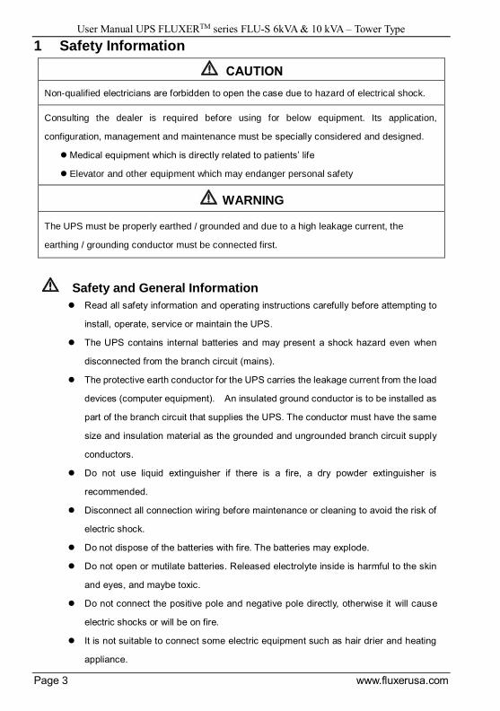
1 Safety Information
CAUTION
Non-qualified electricians are forbidden to open the case due to hazard of electrical shock.
Consulting the dealer is required before using for below equipment. Its application,
configuration, management and maintenance must be specially considered and designed.
Medical equipment which is directly related to patients’ life
Elevator and other equipment which may endanger personal safety
WARNING
The UPS must be properly earthed / grounded and due to a high leakage current, the
earthing / grounding conductor must be connected first.
Safety and General Information Read all safety information and operating instructions carefully before attempting to
install, operate, service or maintain the UPS.
The UPS contains internal batteries and may present a shock hazard even when
disconnected from the branch circuit (mains).
The protective earth conductor for the UPS carries the leakage current from the load
devices (computer equipment). An insulated ground conductor is to be installed as
part of the branch circuit that supplies the UPS. The conductor must have the same
size and insulation material as the grounded and ungrounded branch circuit supply
conductors.
Do not use liquid extinguisher if there is a fire, a dry powder extinguisher is
recommended.
Disconnect all connection wiring before maintenance or cleaning to avoid the risk of
electric shock.
Do not dispose of the batteries with fire. The batteries may explode.
Do not open or mutilate batteries. Released electrolyte inside is harmful to the skin
and eyes, and maybe toxic.
Do not connect the positive pole and negative pole directly, otherwise it will cause
electric shocks or will be on fire.
It is not suitable to connect some electric equipment such as hair drier and heating
appliance.
User Manual UPS FLUXERTM series FLU-S 6kVA & 10 kVA – Tower Type
Page 4 www.fluxerusa.com
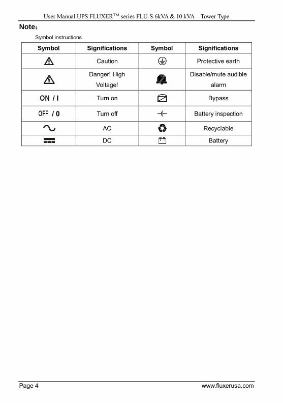
Note:
Symbol instructions
Symbol Significations Symbol Significations
Caution Protective earth
Danger! High
Voltage!
Disable/mute audible
alarm
/ I Turn on Bypass
/ 0 Turn off Battery inspection
AC Recyclable
DC Battery
User Manual UPS FLUXERTM series FLU-S 6kVA & 10 kVA – Tower Type
Page 5 www.fluxerusa.com
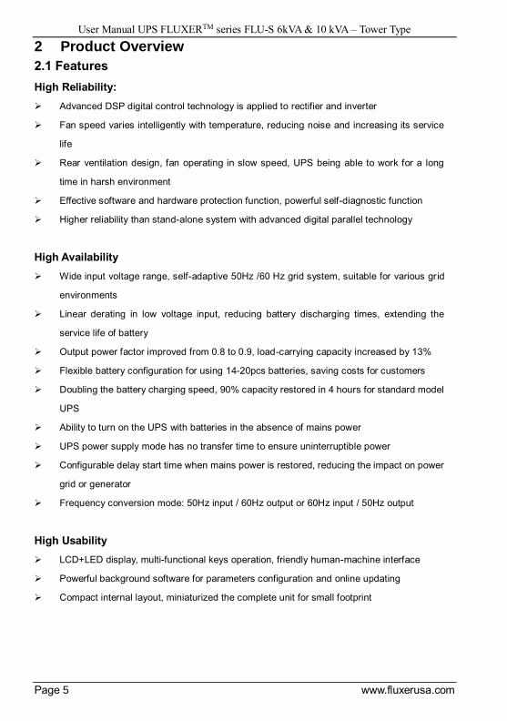
2 Product Overview
2.1 Features
High Reliability:
Advanced DSP digital control technology is applied to rectifier and inverter
Fan speed varies intelligently with temperature, reducing noise and increasing its service
life
Rear ventilation design, fan operating in slow speed, UPS being able to work for a long
time in harsh environment
Effective software and hardware protection function, powerful self-diagnostic function
Higher reliability than stand-alone system with advanced digital parallel technology
High Availability
Wide input voltage range, self-adaptive 50Hz /60 Hz grid system, suitable for various grid
environments
Linear derating in low voltage input, reducing battery discharging times, extending the
service life of battery
Output power factor improved from 0.8 to 0.9, load-carrying capacity increased by 13%
Flexible battery configuration for using 14-20pcs batteries, saving costs for customers
Doubling the battery charging speed, 90% capacity restored in 4 hours for standard model
UPS
Ability to turn on the UPS with batteries in the absence of mains power
UPS power supply mode has no transfer time to ensure uninterruptible power
Configurable delay start time when mains power is restored, reducing the impact on power
grid or generator
Frequency conversion mode: 50Hz input / 60Hz output or 60Hz input / 50Hz output
High Usability
LCD+LED display, multi-functional keys operation, friendly human-machine interface
Powerful background software for parameters configuration and online updating
Compact internal layout, miniaturized the complete unit for small footprint
User Manual UPS FLUXERTM series FLU-S 6kVA & 10 kVA – Tower Type
Page 6 www.fluxerusa.com
High Intelligence
Advanced multi-platform communications: RS232, USB, RS485, SNMP and dry contacts
communication interfaces are used for monitoring UPS running status. Among them, SNMP
is for remote network monitoring and management, by which can configure regular battery
self test.
Intelligent battery management, automatic floating / equalizing charge control, charger
dormancy control, improving the reliability of charger and extending battery service life by
50%;
Energy Conservation and Environment Protection
Active power factor correction (APFC), input power factor up to 0.99;
Work efficiency up to 98% in ECO mode
Auto power On / Off according to the load capacity set by users
Options and Accessories:
Standard RS232 and intelligent slot, optional maintenance bypass, parallel function, battery
temperature compensation, USB, SNMP card, RS485 card, dry contacts card, EMD
environmental sensors and SMS alarms.
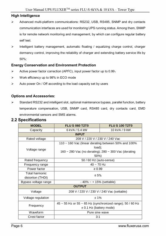
2.2 Specifications
MODEL FLU S 060 T2T0 FLU S 100 T2T0
Capacity 6 kVA / 5.4 kW 10 kVA / 9 kW
INPUT
Rated voltage 208 V / 220 V / 230 V / 240 Vac
Voltage range
110 ~ 160 Vac (linear derating between 50% and 100%
load);
160 ~ 280 Vac (no derating); 280 ~ 300 Vac (derating
50%)
Rated frequency 50 / 60 Hz (auto-sense)
Frequency range 40 ~ 70 Hz
Power factor ≥ 0.99
Total harmonic
distortion (THDI) ≤ 5%
Bypass voltage range - 40% ~ + 15% (settable)
OUTPUT
Voltage 208 V / 220 V / 230 V / 240 Vac (settable)
Voltage regulation ± 1%
Frequency 45 ~ 55 Hz or 55 ~ 65 Hz (synchronized range); 50 / 60 Hz
± 0.1 Hz (battery mode)
Waveform Pure sine wave
Crest factor 3:1

User Manual UPS FLUXERTM series FLU-S 6kVA & 10 kVA – Tower Type
Page 7 www.fluxerusa.com
Total harmonic
distortion (THDV) ≤ 2% (linear load); ≤ 5% (non-linear load)
Transfer time Mains mode to battery mode: 0 ms; Inverter mode to
bypass mode: 0 ms
Inverter overload
capability
102% ~ 125%: Transfer to bypass in 10 min;
125% ~ 150%: Transfer to bypass in 1 min;
> 150%: Transfer to bypass in 0.5 s
Bypass overload
capability
102% ~ 125%: Shut down in 20 min;
125% ~ 150%: Shut down in 2 min;
> 150%: Shut down in 1 s
BATTERIES
DC voltage 192 Vdc (168/180/192/204/216/228/240Vdc optional)
Inbuilt battery of
standard model 16*7 Ah 16* 9 Ah
Recharge time Standard model: 4 hours recover to 90% capacity;
Long time model: depend on the capacity of battery
SYSTEM
EFFICIENCY ≥ 93%, ECO mode 98%
Display LCD+LED
Alarms Battery mode, battery voltage low, fans fault etc.
Maximum Parallel
numbers 6
EMI IEC/EN62040-2
EMS
IEC61000-4-2 (ESD)
IEC61000-4-3 (RS)
IEC61000-4-4 (EFT)
IEC61000-4-5 (Surge)
COMMUNICATIONS
RS232 & intelligent
slot (standard), USB &
RS485 & dry contacts
(optional)
Supports Windows 98 / 2000 / 2003 / XP / Vista / 2008 / 7 /
8 / 10
SNMP (optional) Power management from SNMP manager and web
browser
OTHERS
Humidity 20 ~ 90% RH @ 0 ~ 40℃ (non-condensing)
Noise level ≤ 55 dB (1m)
Dimensions (W*D*H)
(mm) 191×462×350 (H), 191×462×710 (S)
Packaged dimensions
(W*D*H) (mm)
267×573×436 (H)
308×640×896 (S, with battery), 572×790×280 (S, without
battery)
Net weight (kg)
15.6 (H), 58.7 (S, with
battery),
26.7 (S, without battery)
16.1(H), 67.2 (S, with
battery),
27.2 (S, without battery)
Gross weight (kg)
17.9 (H), 64.8 (S, with
battery),
32.8 (S, without battery)
18.4 (H), 73.3 (S, with
battery),
33.3 (S, without battery)
User Manual UPS FLUXERTM series FLU-S 6kVA & 10 kVA – Tower Type
Page 8 www.fluxerusa.com
Derate capacity to 70% in frequency conversion mode and to 90% when the output voltage
is adjusted to 208 Vac.
Derate output PF to 0.7 in battery mode (14pcs batteries) and to 0.8 in battery mode (15pcs
batteries).
S means standard model, H means long time model.
All specifications subject to change without notice.
Custom-made specifications are acceptable.
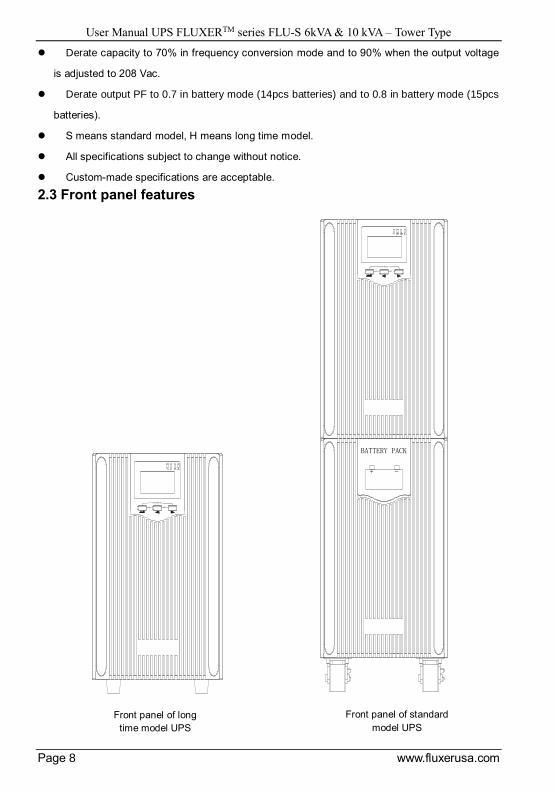
2.3 Front panel features
ON
TEST/MUTE
OFF
BATTERY PACK
+ -
ON
TEST/MUTE
OFF
Front panel of standard
model UPS
Front panel of long
time model UPS

User Manual UPS FLUXERTM series FLU-S 6kVA & 10 kVA – Tower Type
Page 9 www.fluxerusa.com
2.4 Rear panel features
① Input and output terminal ⑧ Intelligent slot (SNMP / AS400 / RS485
optional)
② Input breaker ⑨ USB port(optional)
③ Inbuilt battery breaker ⑨ RS232 port
④ Maintenance switch(optional) ⑪ EPO
⑤ Maintenance switch baffle ⑫ Parallel port (optional)
⑥ Fan ⑬ Battery temperature compensation sensor
(optional)
⑦ External battery connector
1
2
4
5
66
7
8
91011
1213
1
24
5
66
7
8
91011
1213
3
Rear panel of Long backup model UPS
Rear panel of
standard model UPS
User Manual UPS FLUXERTM series FLU-S 6kVA & 10 kVA – Tower Type
Page 10 www.fluxerusa.com
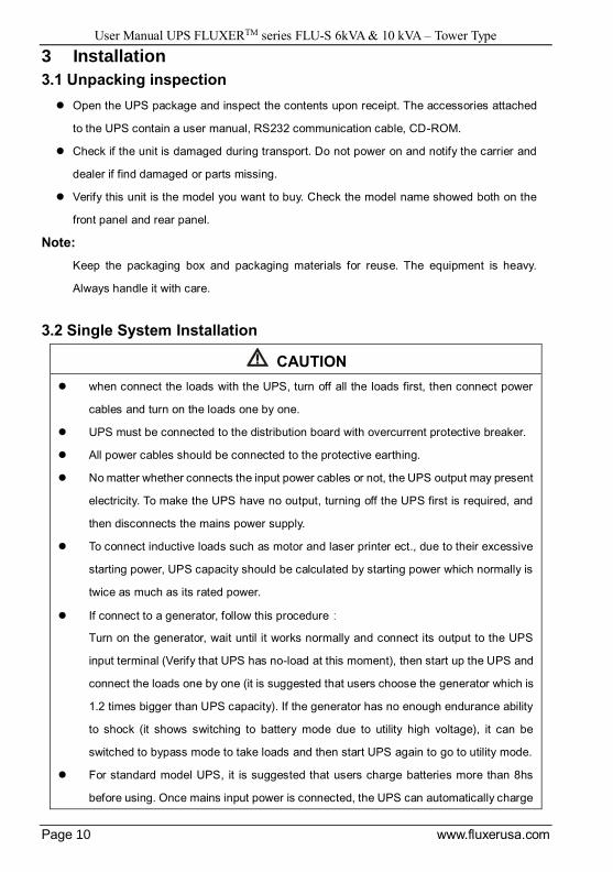
3 Installation
3.1 Unpacking inspection
Open the UPS package and inspect the contents upon receipt. The accessories attached
to the UPS contain a user manual, RS232 communication cable, CD-ROM.
Check if the unit is damaged during transport. Do not power on and notify the carrier and
dealer if find damaged or parts missing.
Verify this unit is the model you want to buy. Check the model name showed both on the
front panel and rear panel.
Note:
Keep the packaging box and packaging materials for reuse. The equipment is heavy.
Always handle it with care.
3.2 Single System Installation
CAUTION
when connect the loads with the UPS, turn off all the loads first, then connect power
cables and turn on the loads one by one.
UPS must be connected to the distribution board with overcurrent protective breaker.
All power cables should be connected to the protective earthing.
No matter whether connects the input power cables or not, the UPS output may present
electricity. To make the UPS have no output, turning off the UPS first is required, and
then disconnects the mains power supply.
To connect inductive loads such as motor and laser printer ect., due to their excessive
starting power, UPS capacity should be calculated by starting power which normally is
twice as much as its rated power.
If connect to a generator, follow this procedure:
Turn on the generator, wait until it works normally and connect its output to the UPS
input terminal (Verify that UPS has no-load at this moment), then start up the UPS and
connect the loads one by one (it is suggested that users choose the generator which is
1.2 times bigger than UPS capacity). If the generator has no enough endurance ability
to shock (it shows switching to battery mode due to utility high voltage), it can be
switched to bypass mode to take loads and then start UPS again to go to utility mode.
For standard model UPS, it is suggested that users charge batteries more than 8hs
before using. Once mains input power is connected, the UPS can automatically charge

User Manual UPS FLUXERTM series FLU-S 6kVA & 10 kVA – Tower Type
Page 11 www.fluxerusa.com
the battery. Even not charge, it can be used at once, but its backup time will be less
than standard value.
After finishing installation, verify that the installation is correct.
If install the protective leakage current switch, it should be installed on the UPS output
terminal.
3.2.1 Installation environment and location
Install the UPS system in a temperature-controlled environment free of conductive
contaminants and humidity.
Install the UPS system on a non-flammable, level and solid surface (e.g. concrete) that can
support the weight of the system.
The UPS system cannot be placed up against the wall. Keep adequate space for proper
ventilation of air inlet in the bottom of front panel, air outlet of fans on the rear cover plate
and air inlet of enclosure sides.
The ambient temperature of the UPS should be 0 °C to 40 °C.
There may be condensing If unpacking in low temperature, the UPS must be waited until
inside and outside of the UPS are completely dry for installation, otherwise there is hazard
of electric shock.
Place the UPS close to the mains input power distribution so as to cut off mains input switch
and power supply in emergency situation.
3.2.2 Wiring
The UPS system uses terminal block for input and output connections.
The requirements for the cable current are as follows:
Model Maximum current(A)
Input Battery Output
6kVA 41.8 37.5 27.3
10kVA 66.3 62.5 45.5
--+BATTERY
Input L
Input N
Output L
Output NPE
Battery
+ -
L N N L

User Manual UPS FLUXERTM series FLU-S 6kVA & 10 kVA – Tower Type
Page 12 www.fluxerusa.com
Terminal block
Note:
Ensure that the input / output cables must be connected firmly to the input / output terminals,
bad contacts are not allowable. It is suggested that the earth wire is close to the input /
output wire size.
The requirements for wiring diameter are as follows:
Model Wiring spec(mm2)
Input Battery Output Earth wire
6kVA 6 6 6 6
10kVA 10 10 10 10
Note:
It is need to select proper cable for long-lasting device to connect battery and UPS, and a
DC breaker should be connected between battery and UPS.
1-meter space should be spared before and after UPS host for avoiding foreign matters
blocking the air duct of UPS.
The requirements for wiring brass terminal are as follows:
Model Wiring spec(mm2)
Input Battery Output Earth wire
6kVA 8-5S / 8-5S 8-5S
10kVA 8-5S / 8-5S 8-5S
Note:
The recommended torque of screws on terminal block is 1.765N.M or 18kgf.cm.
Long backup mode UPS contains one external battery connector wire, standard mode UPS
don’t contain the wire.
The requirements for external breaker configuration are as follows:
Model Specification of external breaker
Input Battery Output
6kVA 63A/2P 40A/2P (3P)/
220VDC 32A/2P
10kVA 100A/2P 63A/2P (3P)/
220VDC 50A/2P
User Manual UPS FLUXERTM series FLU-S 6kVA & 10 kVA – Tower Type
Page 13 www.fluxerusa.com
Note:
It is recommended that the input external breaker is two levels larger than the internal
breaker of UPS. Model need be selected according to the characteristics of switch trip in
different brands and different modes as well as the system configuration for ensuring
reasonable mode selection of breaker cascade between upper and lower levels.
There is no output breaker in the interior of UPS, which needs to be configured by users.
Maintenance switch is optional, and it’s a rotary switch.
For the configuration of 16 batteries, the DC withstand voltage of battery breaker should be
higher than 220VDC; for the configuration of 20 batteries, the DC withstand voltage of
battery breaker should be higher than 270VDC. You can select the 3P breaker if the 2P
breaker cannot meet the demand of the configurations, thereinto 2P should be used in
series.
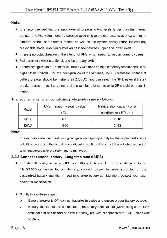
The requirements for air conditioning refrigeration are as follows:
Model UPS maximum calorific value
(W)
Refrigeration capacity of air
conditioning(BTU/H)
6kVA 600 2048
10kVA 1000 3413
Note:
The recommended air conditioning refrigeration capacity is only for the single heat source
of UPS in room, and the actual air conditioning configuration should be selected according
to all heat sources in the room and room layout.
3.2.3 Connect external battery (Long time model UPS)
The default configuration of UPS use 16pcs batteries. If it was customized to be
14/16/18/20pcs before factory delivery, connect proper batteries according to the
customized battery quantity. If need to change battery configuration, contact your local
dealer for modification.
Strictly follow these steps:
Battery breaker is Off, connect batteries in series and ensure proper battery voltage.
Battery cables must be connected to the battery terminal first (Connecting to the UPS
terminal first has hazard of electric shock), red wire is connected to BAT+, black wire
to BAT-.
User Manual UPS FLUXERTM series FLU-S 6kVA & 10 kVA – Tower Type
Page 14 www.fluxerusa.com
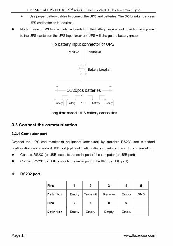
Use proper battery cables to connect the UPS and batteries. The DC breaker between
UPS and batteries is required.
Not to connect UPS to any loads first, switch on the battery breaker and provide mains power
to the UPS (switch on the UPS input breaker), UPS will charge the battery group.
Long time model UPS battery connection
3.3 Connect the communication
3.3.1 Computer port
Connect the UPS and monitoring equipment (computer) by standard RS232 port (standard
configuration) and standard USB port (optional configuration) to make single unit communication.
Connect RS232 (or USB) cable to the serial port of the computer (or USB port)
Connect RS232 (or USB) cable to the serial port of the UPS (or USB port)
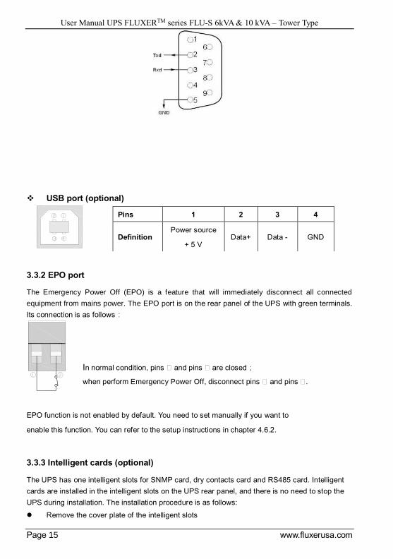
RS232 port
Battery
+ - + - + - + -
...
...
To battery input connector of UPS
Positive negative
16/20pcs batteries
Battery breaker
Battery Battery Battery
+ -
Pins 1 2 3 4 5
Definition Empty Transmit Receive Empty GND
Pins 6 7 8 9
Definition Empty Empty Empty Empty
User Manual UPS FLUXERTM series FLU-S 6kVA & 10 kVA – Tower Type
Page 15 www.fluxerusa.com
USB port (optional)
3.3.2 EPO port
The Emergency Power Off (EPO) is a feature that will immediately disconnect all connected
equipment from mains power. The EPO port is on the rear panel of the UPS with green terminals.
Its connection is as follows:
EPO function is not enabled by default. You need to set manually if you want to
enable this function. You can refer to the setup instructions in chapter 4.6.2.
3.3.3 Intelligent cards (optional)
The UPS has one intelligent slots for SNMP card, dry contacts card and RS485 card. Intelligent
cards are installed in the intelligent slots on the UPS rear panel, and there is no need to stop the
UPS during installation. The installation procedure is as follows:
Remove the cover plate of the intelligent slots
Pins 1 2 3 4
Definition Power source
+ 5 V Data+ Data - GND
In normal condition, pins ⑨ and pins ⑨ are closed;
when perform Emergency Power Off, disconnect pins ⑨ and pins ⑨.
User Manual UPS FLUXERTM series FLU-S 6kVA & 10 kVA – Tower Type
Page 16 www.fluxerusa.com
Insert the required intelligent card into the slot
Tighten the screws
SNMP card (optional)
SNMP is used in network management systems to communicate, manage and monitor UPS
devices, it could be compatible with current popular software , hardware and network operating
system.
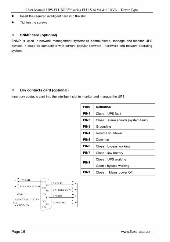
Dry contacts card (optional)
Insert dry contacts card into the intelligent slot to monitor and manage the UPS.
Pins Definition
PIN1 Close:UPS fault
PIN2 Close:Alarm sounds (system fault)
PIN3 Grounding
PIN4 Remote shutdown
PIN5 Common
PIN6 Close:bypass working
PIN7 Close:low battery
PIN8 Close:UPS working
Open:bypass working
PIN9 Close: Mains power Off
User Manual UPS FLUXERTM series FLU-S 6kVA & 10 kVA – Tower Type
Page 17 www.fluxerusa.com
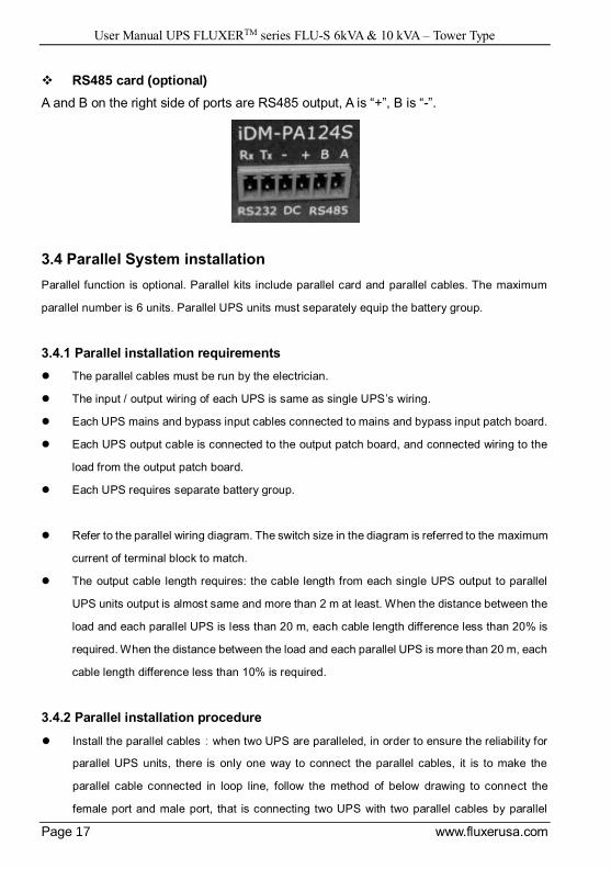
RS485 card (optional)
A and B on the right side of ports are RS485 output, A is “+”, B is “-”.
3.4 Parallel System installation
Parallel function is optional. Parallel kits include parallel card and parallel cables. The maximum
parallel number is 6 units. Parallel UPS units must separately equip the battery group.
3.4.1 Parallel installation requirements
The parallel cables must be run by the electrician.
The input / output wiring of each UPS is same as single UPS’s wiring.
Each UPS mains and bypass input cables connected to mains and bypass input patch board.
Each UPS output cable is connected to the output patch board, and connected wiring to the
load from the output patch board.
Each UPS requires separate battery group.
Refer to the parallel wiring diagram. The switch size in the diagram is referred to the maximum
current of terminal block to match.
The output cable length requires: the cable length from each single UPS output to parallel
UPS units output is almost same and more than 2 m at least. When the distance between the
load and each parallel UPS is less than 20 m, each cable length difference less than 20% is
required. When the distance between the load and each parallel UPS is more than 20 m, each
cable length difference less than 10% is required.
3.4.2 Parallel installation procedure
Install the parallel cables:when two UPS are paralleled, in order to ensure the reliability for
parallel UPS units, there is only one way to connect the parallel cables, it is to make the
parallel cable connected in loop line, follow the method of below drawing to connect the
female port and male port, that is connecting two UPS with two parallel cables by parallel
User Manual UPS FLUXERTM series FLU-S 6kVA & 10 kVA – Tower Type
Page 18 www.fluxerusa.com
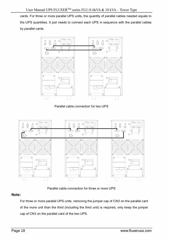
cards. For three or more parallel UPS units, the quantity of parallel cables needed equals to
the UPS quantities. It just needs to connect each UPS in sequence with the parallel cables
by parallel cards.
Parallel cable connection for two UPS
Parallel cable connection for three or more UPS
Note:
For three or more parallel UPS units, removing the jumper cap of CN3 on the parallel card
of the more unit than the third (including the third unit) is required, only keep the jumper
cap of CN3 on the parallel card of the two UPS.
User Manual UPS FLUXERTM series FLU-S 6kVA & 10 kVA – Tower Type
Page 19 www.fluxerusa.com
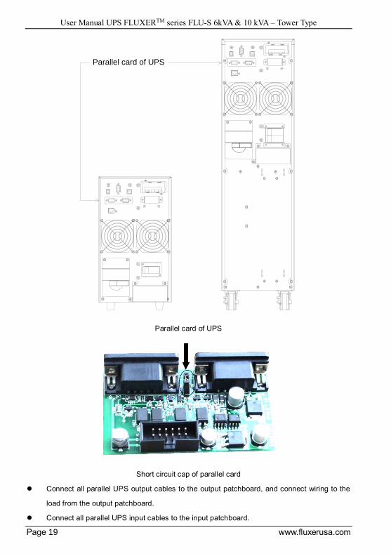
Parallel card of UPS
Short circuit cap of parallel card
Connect all parallel UPS output cables to the output patchboard, and connect wiring to the
load from the output patchboard.
Connect all parallel UPS input cables to the input patchboard.
Parallel card of UPS

User Manual UPS FLUXERTM series FLU-S 6kVA & 10 kVA – Tower Type
Page 20 www.fluxerusa.com
Parallel UPS connection
Two parallel UPS connection
For standard model UPS, each UPS has inbuilt battery group; for long time model UPS, it
needs to equip separated external battery group.
Verify all connection after parallel installation is completed. Operate the parallel UPS after
confirming correct.
In the condition of each single UPS running, set the physical address (ID) of each UPS, and
ensure that each ID is different.
In the condition of each single UPS running, set the output voltage (OPU) of each UPS, and
ensure that each OPU is same.
Verify if the parallel cables of all UPS are connected firmly, perform startup and finish parallel
installation.
INPUTOUTPUT
N
PE
L N N L--+
BATTERY
L N N L--+
BATTERY
BATTERY 1
+ -
BATTERY 2
+ -
L LNPE
Load Load Load Load ...
Mains input
Public input terminal
Public output terminal block
User Manual UPS FLUXERTM series FLU-S 6kVA & 10 kVA – Tower Type
Page 21 www.fluxerusa.com
4 Operation Instructions
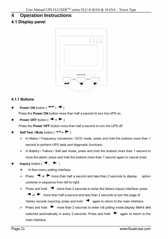
4.1 Display panel
4.1.1 Buttons
Power ON button ( + )
Press the Power ON button more than half a second to turn the UPS on.
Power OFF button ( + )
Press the Power OFF button more than half a second to turn the UPS off.
Self Test / Mute button ( + )
In Mains / Frequency conversion / ECO mode, press and hold the buttons more than 1
second to perform UPS tests and diagnostic functions.
In Battery / Failure / Self test mode, press and hold the buttons more than 1 second to
mute the alarm; press and hold the buttons more than 1 second again to cancel mute;
Inquiry button ( , )
In Non-menu setting interface:
Press or more than half a second and less than 2 seconds to display option
contents in sequence from left to right.
Press and hold more than 2 seconds to enter the history inquiry interface; press
or more than half a second and less than 2 seconds to turn the page of
history records inquiring; press and hold again to return to the main interface.
Press and hold more than 2 seconds to enter roll polling mode,display items are
switched automatically in every 2 seconds. Press and hold again to return to the
main interface.
ON
TEST/MUTE
OFF
User Manual UPS FLUXERTM series FLU-S 6kVA & 10 kVA – Tower Type
Page 22 www.fluxerusa.com
In menu setting interface:
Press or more than half a second and less than 2 seconds to select setting
options.
Menu settings button ( )
In Non-menu setting interface:
Press and hold more than 2 seconds to enter the menu settings interface.
In menu setting interface:
Press more than half a second and less than 2 seconds to confirm the setting
option.
Press and hold more than 2 seconds to exit the menu setting interface.
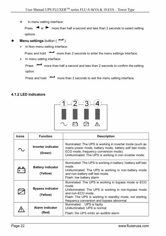
4.1.2 LED indicators
Icons Function Description
Inverter indicator
(Green)
Illuminated: The UPS is working in inverter mode (such as
mains power mode, battery mode, battery self test mode, ECO mode, frequency conversion mode). Unilluminated: The UPS is working in non-inverter mode.
Battery indicator
(Yellow)
Illuminated: The UPS is working in battery / battery self test
mode. Unilluminated: The UPS is working in non-battery mode and non-battery self test mode.
Flash: low battery alarm
Bypass indicator
(Yellow)
Illuminated: The UPS is working in bypass mode or ECO mode.
Unilluminated: The UPS is working in non-bypass mode and non-ECO mode. Flash: The UPS is working in standby mode, not starting
frequency conversion and bypass abnormal
Alarm indicator
(Red)
Illuminated: UPS is faulty Unilluminated: UPS is normal
Flash: the UPS emits an audible alarm
User Manual UPS FLUXERTM series FLU-S 6kVA & 10 kVA – Tower Type
Page 23 www.fluxerusa.com
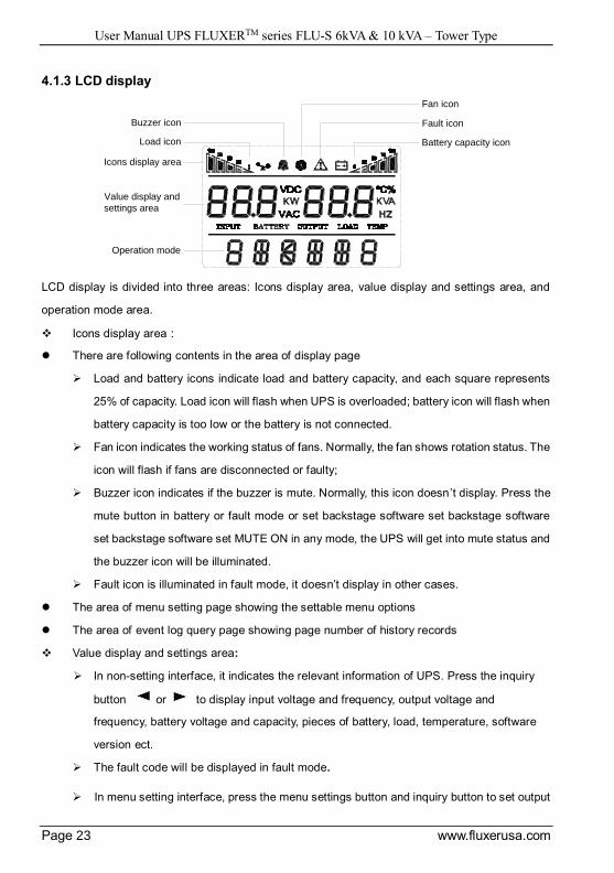
4.1.3 LCD display
LCD display is divided into three areas: Icons display area, value display and settings area, and
operation mode area.
Icons display area:
There are following contents in the area of display page
Load and battery icons indicate load and battery capacity, and each square represents
25% of capacity. Load icon will flash when UPS is overloaded; battery icon will flash when
battery capacity is too low or the battery is not connected.
Fan icon indicates the working status of fans. Normally, the fan shows rotation status. The
icon will flash if fans are disconnected or faulty;
Buzzer icon indicates if the buzzer is mute. Normally, this icon doesn’t display. Press the
mute button in battery or fault mode or set backstage software set backstage software
set backstage software set MUTE ON in any mode, the UPS will get into mute status and
the buzzer icon will be illuminated.
Fault icon is illuminated in fault mode, it doesn’t display in other cases.
The area of menu setting page showing the settable menu options
The area of event log query page showing page number of history records
Value display and settings area:
In non-setting interface, it indicates the relevant information of UPS. Press the inquiry
button or to display input voltage and frequency, output voltage and
frequency, battery voltage and capacity, pieces of battery, load, temperature, software
version ect.
The fault code will be displayed in fault mode.
In menu setting interface, press the menu settings button and inquiry button to set output
Fan icon
Fault icon
Battery capacity icon
Buzzer icon
Load icon
Icons display area
Value display and
settings area
Operation mode

User Manual UPS FLUXERTM series FLU-S 6kVA & 10 kVA – Tower Type
Page 24 www.fluxerusa.com
voltage value (OPU), physical address(Id), parallel Enable (PAL), end of discharge point
(Eod), checking status OFF (CHE)、Expert mode (EP), Clear warning function(CLE)、
Battery numbers(PCS)、Emergency power off (EPO),etc.
Operation mode area:
After starting up in 20 seconds, this display area mainly indicates the UPS power rating.
This display area mainly indicates the UPS operation mode in 20 seconds after starting
up, such as STdby (Standby mode), byPASS (Bypass mode), Line (Utility mode), bAT
(Bttery mode), bATT (Bttery self test mode), FAULT (Fault mode), FC (Frequency
conversion mode), ECO (economy mode), SHUTdn (Shutdown mode), TEST (Test mode).
4.1.4 Equivalent UPS working status to the indicator
Buzzer sound Description
Long beep Fault mode
1 s per beep Low battery in battery mode
Output overload
2 min per beep The inverter is not open
4 s per beep All other alarms
Item Working status The panel indicator display
Audible alarm Normal Battery Bypass Fault
1 Utility mode / Frequency conversion mode
No any fault alarm ● No
Alarm exists ● ★ 1/ 4 s per beep
2 Battery mode
Non-low battery
alarm ● ● ★ 4 s per beep
Low battery alarm ● ★ ★ 1 s per beep
3
Battery self test
mode / Starting
process
★ ★ ★ ★ 4 s per beep
4 Bypass mode
No any fault alarm ● 2 minper beep
Alarm exists ● ★ 1/ 4 s per beep
5 ECO mode
● ● No
Alarm exists ● ● ★ 1/ 4 s per beep
6 Fault mode ● Long beep
● _ The indicator is illuminated.
User Manual UPS FLUXERTM series FLU-S 6kVA & 10 kVA – Tower Type
Page 25 www.fluxerusa.com
⑨ _ The indicator flashes.
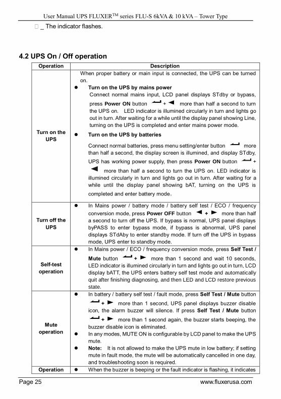
4.2 UPS On / Off operation
Operation Description
Turn on the
UPS
When proper battery or main input is connected, the UPS can be turned
on.
Turn on the UPS by mains power
Connect normal mains input, LCD panel displays STdby or bypass,
press Power ON button + more than half a second to turn
the UPS on. LED indicator is illumined circularly in turn and lights go
out in turn. After waiting for a while until the display panel showing Line,
turning on the UPS is completed and enter mains power mode.
Turn on the UPS by batteries
Connect normal batteries, press menu setting/enter button more
than half a second, the display screen is illumined, and display STdby,
UPS has working power supply, then press Power ON button +
more than half a second to turn the UPS on. LED indicator is
illumined circularly in turn and lights go out in turn. After waiting for a
while until the display panel showing bAT, turning on the UPS is
completed and enter battery mode。
Turn off the
UPS
In Mains power / battery mode / battery self test / ECO / frequency
conversion mode, press Power OFF button + more than half
a second to turn off the UPS. If bypass is normal, UPS panel displays
byPASS to enter bypass mode, if bypass is abnormal, UPS panel
displays STdAby to enter standby mode. If turn off the UPS in bypass
mode, UPS enter to standby mode.
Self-test
operation
In Mains power / ECO / frequency conversion mode, press Self Test /
Mute button + more than 1 second and wait 10 seconds,
LED indicator is illumined circularly in turn and lights go out in turn, LCD
display bATT, the UPS enters battery self test mode and automatically
quit after finishing diagnosing, and then LED and LCD restore previous
state.
Mute
operation
In battery / battery self test / fault mode, press Self Test / Mute button
+ more than 1 second, UPS panel displays buzzer disable
icon, the alarm buzzer will silence. If press Self Test / Mute button
+ more than 1 second again, the buzzer starts beeping, the
buzzer disable icon is eliminated.
In any modes, MUTE ON is configurable by LCD panel to make the UPS
mute.
Note: It is not allowed to make the UPS mute in low battery; if setting
mute in fault mode, the mute will be automatically cancelled in one day,
and troubleshooting soon is required.
Operation When the buzzer is beeping or the fault indicator is flashing, it indicates
User Manual UPS FLUXERTM series FLU-S 6kVA & 10 kVA – Tower Type
Page 26 www.fluxerusa.com
in audible
alarm
status
that the UPS is in alarm status, troubleshooting can be done by the
alarm information displayed on the LCD panel.
Operation
in fault
mode
When the sound of the UPS buzzer lingers on and the fault indicator is
illuminated, it indicates that the UPS enter fault mode, contact your
supplier or serviceman and provide them with failure information.
4.3 Parallel UPS operation
Follow single UPS operation requirements for general operation of parallel system. Before
turning on the parallel UPS units, setting the physical address (ID) of each UPS is required,
ensure each ID is different. Refer to panel settings operation for setting method details.
4.3.1 Start up parallel UPS
Startup with mains power:After access mains power, press the Power ON button +
of any one of UPS more than half a second to start up parallel UPS. All UPS units will
be turned on at same time, then meanwhile switch to inverter status, working in mains power
mode.
Startup with the battery: Method 1: press first key of each UPS, after each UPS
having working power source, press the Power ON button + of any one of UPS
more than half a second to start up parallel UPS. All UPS units will be turned on at same time,
then meanwhile switch to inverter status, working in mains power mode. Method 2: Execute
startup operation on each UPS one by one.
4.3.2 Shut down parallel UPS
Keep pressing the Power OFF button + of any one of UPS more than 4 seconds to
turn off parallel UPS units; press the Power OFF button + of any one of UPS more
than half a second and less than 4 seconds to turn off the single UPS unit.
4.3.3 Parallel UPS system maintenance
Follow single UPS maintenance requirements for parallel system maintenance. If one of
parallel system UPS fails and need to maintain it, firstly it is required to cut off the breaker
between input / output of the faulty UPS and parallel system, ensure that there is no electrical
connection for the faulty UPS and parallel system, then disconnect all parallel cables of the
faulty UPS and parallel system, and then make maintenance operation for the faulty one.
4.4 Maintenance switch (optional)
Maintenance switch is for UPS on-line maintenance, follow below procedures:
Open the cover plate of the maintenance switch on the UPS rear panel, the UPS will
automatically transfer to bypass to supply power to the load.

User Manual UPS FLUXERTM series FLU-S 6kVA & 10 kVA – Tower Type
Page 27 www.fluxerusa.com
Make the maintenance switch at “BYPASS”.
Disconnect all input / battery breakers.
Wait until the display screen is extinguished completely and on standing for 10 mins, make
sure there is no hazard of electrical shock inside the UPS, and you can do on-line
maintenance for the UPS.
After finishing on-line maintenance, close the input breaker first, then make the maintenance
switch at “UPS” end, and then install the cover plate of the maintenance switch.
Note:
Make sure the system bypass is normal and not to start frequency conversion, otherwise it
may cause power failure or even damage to loads.
If the UPS has no output and needs manual on-line maintenance, disconnect all input breaker and
ensure the UPS display screen is extinguished, then put the maintenance switch to “BYPASS” by
hand, otherwise it may cause damage to the UPS.
4.5 Parameters inquiry
Press inquiry button or more than half a second and less than 2 seconds to inquire
in sequence for some information about input, battery, output, load, software version,
temperature ect., 6 pages in total.If warning happened,it will have a warning code page.
Press and hold inquiry button more than 2 seconds to enter roll polling mode display,
automatically switch display items in every 2 seconds, and go back to the default status
displaying output information in 30 seconds. If press and hold again within 30 seconds,
it will go back to the main interface immediately.
Interface Page 1 (output interface): Display UPS output information, as shown below:
User Manual UPS FLUXERTM series FLU-S 6kVA & 10 kVA – Tower Type
Page 28 www.fluxerusa.com
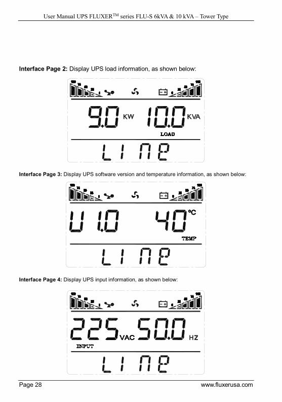
Interface Page 2: Display UPS load information, as shown below:
Interface Page 3: Display UPS software version and temperature information, as shown below:
Interface Page 4: Display UPS input information, as shown below:

User Manual UPS FLUXERTM series FLU-S 6kVA & 10 kVA – Tower Type
Page 29 www.fluxerusa.com
Interface Page 5: Display UPS battery voltage, battery capacity percentage, as shown below:
Interface Page 6: Display UPS battery numbers, as shown below:
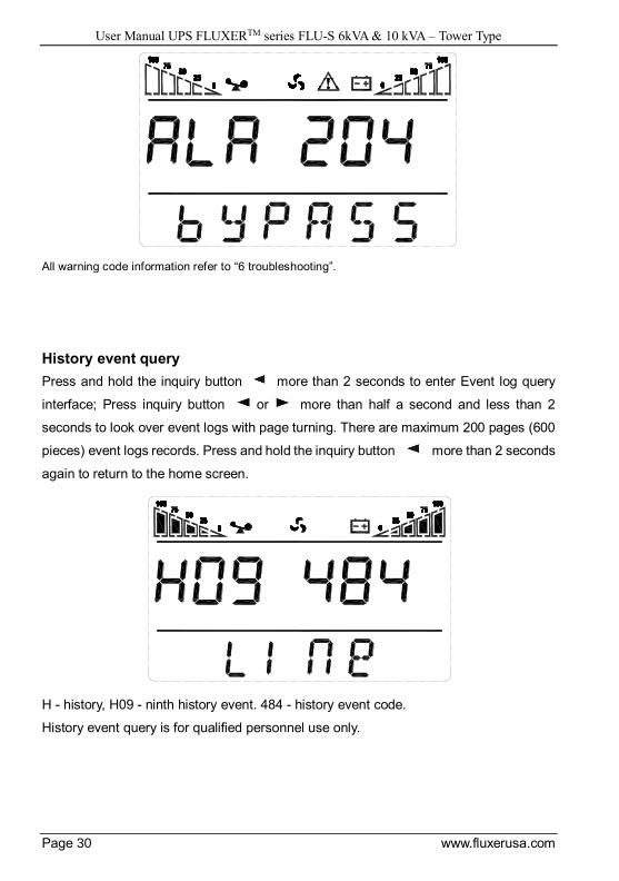
Warning code Page :Display UPS warning code, as shown below (ALA means alarm):
User Manual UPS FLUXERTM series FLU-S 6kVA & 10 kVA – Tower Type
Page 30 www.fluxerusa.com
All warning code information refer to “6 troubleshooting”.
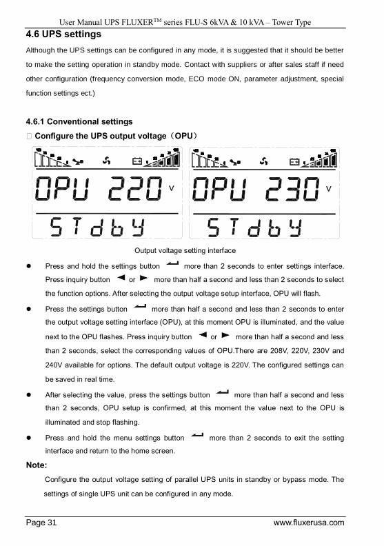
History event query
Press and hold the inquiry button more than 2 seconds to enter Event log query
interface; Press inquiry button or more than half a second and less than 2
seconds to look over event logs with page turning. There are maximum 200 pages (600
pieces) event logs records. Press and hold the inquiry button more than 2 seconds
again to return to the home screen.
H - history, H09 - ninth history event. 484 - history event code.
History event query is for qualified personnel use only.
User Manual UPS FLUXERTM series FLU-S 6kVA & 10 kVA – Tower Type
Page 31 www.fluxerusa.com
4.6 UPS settings
Although the UPS settings can be configured in any mode, it is suggested that it should be better
to make the setting operation in standby mode. Contact with suppliers or after sales staff if need
other configuration (frequency conversion mode, ECO mode ON, parameter adjustment, special
function settings ect.)
4.6.1 Conventional settings
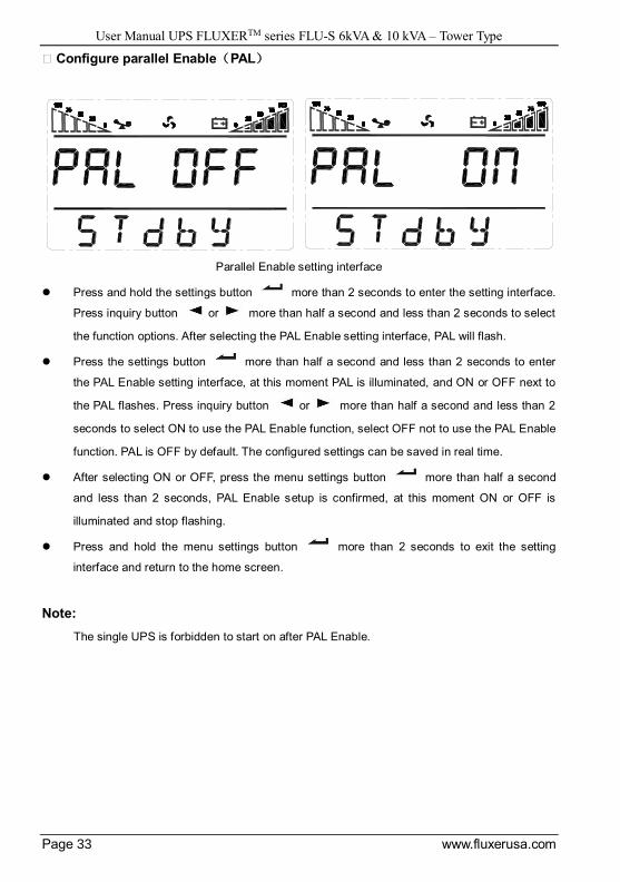
※ Configure the UPS output voltage(OPU)
Output voltage setting interface
Press and hold the settings button more than 2 seconds to enter settings interface.
Press inquiry button or more than half a second and less than 2 seconds to select
the function options. After selecting the output voltage setup interface, OPU will flash.
Press the settings button more than half a second and less than 2 seconds to enter
the output voltage setting interface (OPU), at this moment OPU is illuminated, and the value
next to the OPU flashes. Press inquiry button or more than half a second and less
than 2 seconds, select the corresponding values of OPU.There are 208V, 220V, 230V and
240V available for options. The default output voltage is 220V. The configured settings can
be saved in real time.
After selecting the value, press the settings button more than half a second and less
than 2 seconds, OPU setup is confirmed, at this moment the value next to the OPU is
illuminated and stop flashing.
Press and hold the menu settings button more than 2 seconds to exit the setting
interface and return to the home screen.
Note:
Configure the output voltage setting of parallel UPS units in standby or bypass mode. The
settings of single UPS unit can be configured in any mode.

User Manual UPS FLUXERTM series FLU-S 6kVA & 10 kVA – Tower Type
Page 32 www.fluxerusa.com
※ Configure the physical address (Id)
physical address setting interface
Press and hold the settings button more than 2 seconds to enter the setting interface.
Press inquiry button or more than half a second and less than 2 seconds to select
the function options. After selecting the ID setting interface, ID will flash.
Press the menu settings button more than half a second and less than 2 seconds to
enter the ID setting interface, at this moment ID is illuminated, and the value next to the ID
flashes. Press inquiry button or more than half a second and less than 2 seconds
to select the corresponding value of ID function. There are 1/2/3/4/5/6 available for options.
The default address is 1. The configured settings can be saved in real time.
After selecting the address, press the menu settings button more than half a second
and less than 2 seconds, ID setup is confirmed, at this moment the selected value is
illuminated and stop flashing.
Press and hold the settings button more than 2 seconds to exit the setting interface
and return to the home screen.
Note:
The physical address setting can be only configured in case of single UPS operating, it cannot
be done in parallel UPS units.
User Manual UPS FLUXERTM series FLU-S 6kVA & 10 kVA – Tower Type
Page 33 www.fluxerusa.com
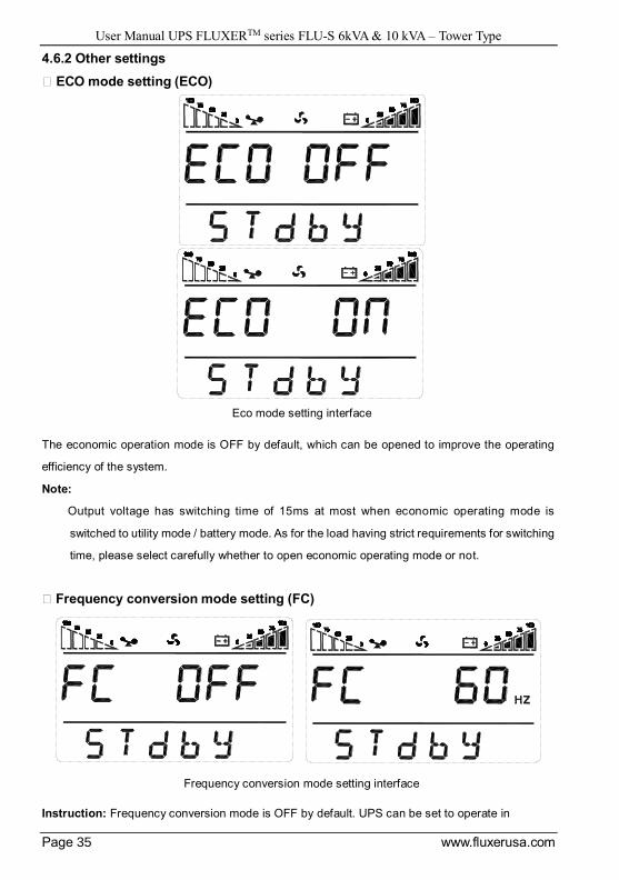
※ Configure parallel Enable(PAL)
Parallel Enable setting interface
Press and hold the settings button more than 2 seconds to enter the setting interface.
Press inquiry button or more than half a second and less than 2 seconds to select
the function options. After selecting the PAL Enable setting interface, PAL will flash.
Press the settings button more than half a second and less than 2 seconds to enter
the PAL Enable setting interface, at this moment PAL is illuminated, and ON or OFF next to
the PAL flashes. Press inquiry button or more than half a second and less than 2
seconds to select ON to use the PAL Enable function, select OFF not to use the PAL Enable
function. PAL is OFF by default. The configured settings can be saved in real time.
After selecting ON or OFF, press the menu settings button more than half a second
and less than 2 seconds, PAL Enable setup is confirmed, at this moment ON or OFF is
illuminated and stop flashing.
Press and hold the menu settings button more than 2 seconds to exit the setting
interface and return to the home screen.
Note:
The single UPS is forbidden to start on after PAL Enable.

User Manual UPS FLUXERTM series FLU-S 6kVA & 10 kVA – Tower Type
Page 34 www.fluxerusa.com
※ Checking status (CHE)
Checking status setting interface
Power up again after power off in fault mode, the UPS enters checking status (CHE). Judge
if keep bypass output and forbid turning on the UPS according to the fault information. It is
not allowed to turn on the UPS until failure is solved and manually close CHE.
Press and hold the settings button more than 2 seconds to enter the setting interface.
Press inquiry button or more than half a second and less than 2 seconds to select
the function options. After selecting CHE setting interface, CHE will flash.
Press the settings button more than half a second and less than 2 seconds to enter
the CHE setting interface, at this moment CHE is illuminated, and ON next to the CHE flashes.
Press inquiry button or more than half a second and less than 2 seconds and select
OFF, at this moment OFF flashes.
After selecting OFF, press the settings button more than half a second and less than 2
seconds, CHE Enable is confirmed, at this moment OFF next to the CHE is illuminated and
stop flashing.
Press and hold the menu settings button more than 2 seconds to exit the setting
interface and return to the home screen displaying UPS output information.
Power up again after power off, the UPS enter normal mode.
Note:
The function setting interface will not have CHE option until failure, there is no CHE option
when the UPS is normal.
User Manual UPS FLUXERTM series FLU-S 6kVA & 10 kVA – Tower Type
Page 35 www.fluxerusa.com
4.6.2 Other settings
※ ECO mode setting (ECO)
Eco mode setting interface
The economic operation mode is OFF by default, which can be opened to improve the operating
efficiency of the system.
Note:
Output voltage has switching time of 15ms at most when economic operating mode is
switched to utility mode / battery mode. As for the load having strict requirements for switching
time, please select carefully whether to open economic operating mode or not.
※ Frequency conversion mode setting (FC)
Frequency conversion mode setting interface
Instruction: Frequency conversion mode is OFF by default. UPS can be set to operate in
User Manual UPS FLUXERTM series FLU-S 6kVA & 10 kVA – Tower Type
Page 36 www.fluxerusa.com
frequency conversion mode, and you can select output of 50Hz or 60Hz.
Note:
UPS operates in frequency conversion mode without bypass function, and the output capacity
drops to 70%.
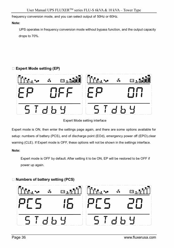
※ Expert Mode setting (EP)
Expert Mode setting interface
Expert mode is ON, then enter the settings page again, and there are some options available for
setup: numbers of battery (PCS), end of discharge point (EOd), emergency power off (EPO),clear
warning (CLE). If Expert mode is OFF, these options will not be shown in the settings interface.
Note:
Expert mode is OFF by default. After setting it to be ON, EP will be restored to be OFF if
power up again.
※ Numbers of battery setting (PCS)

User Manual UPS FLUXERTM series FLU-S 6kVA & 10 kVA – Tower Type
Page 37 www.fluxerusa.com
Note:
When set EP as ON, PCS option shows up in the setting interface, allows to configurate the
number of batteries.There are 14/15/16/17/18/19/20 pcs of batteries for options,and the default
value is 16.
※ End of discharge point setting (EOd)
End of discharge point setting interface
Note:
When set EP as ON, PCS option shows up in the setting interface, allows to configurate the
number of batteries. There are dEF, 9.8V, 9.9V, 10V, 10.2V and 10.5V available for options.
EOd is dEF by default (Eod varies with load).
The low voltage alarm point of each battery is (Eod + 1V) (Battery low voltage shutdown point +
1V)×Numbers of battery.
※ Emergency power off setting (EPO)
Emergency power off setting interface
User Manual UPS FLUXERTM series FLU-S 6kVA & 10 kVA – Tower Type
Page 38 www.fluxerusa.com
Note:
When set EP as ON, EPO option shows up in the setting interface, allows to configurate the
emergency power off. Emergency power off function is Off by default, which can be selected
to open this function. Thereinto EPO OFF indicates that emergency power off function is not
opened; EPO ONb indicates that emergency power off function is opened, the output will be
implemented by bypass after emergency shutdown; EPO ONF indicates that emergency power
off function is opened, output will be cut off after emergency shutdown.
After setting EPO Onb, the output power fails when emergency power off.
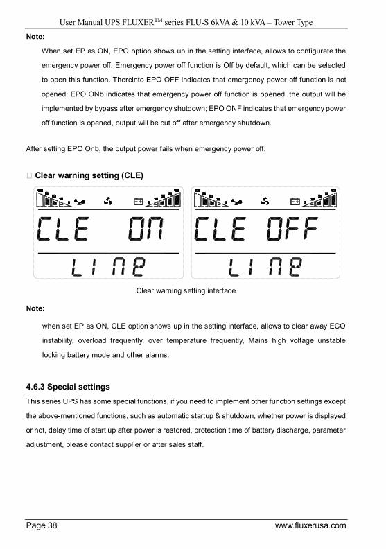
※ Clear warning setting (CLE)
Clear warning setting interface
Note:
when set EP as ON, CLE option shows up in the setting interface, allows to clear away ECO
instability, overload frequently, over temperature frequently, Mains high voltage unstable
locking battery mode and other alarms.
4.6.3 Special settings
This series UPS has some special functions, if you need to implement other function settings except
the above-mentioned functions, such as automatic startup & shutdown, whether power is displayed
or not, delay time of start up after power is restored, protection time of battery discharge, parameter
adjustment, please contact supplier or after sales staff.
User Manual UPS FLUXERTM series FLU-S 6kVA & 10 kVA – Tower Type
Page 39 www.fluxerusa.com
5 Operation Modes
This UPS is a kind of on-line dual conversion UPS, which has following operation modes:
Power-up mode (LCD display power capacity)
Standby mode (Stdby)
Bypass mode (byPASS)
Mains power mode (LInE)
Battery mode (bAT)
Battery self test (bATT)
Fault mode (FAULT)
Frequency conversion mode (FC)
Economy control operation (ECO)
Shutdown mode (SHUTdn)
Test mode (TEST)
Maintenance bypass mode (manual operation)
5.1 Power-up mode / Shutdown mode
In the condition of power off and the display screen being black out, connect batteries and press
first key or connect mains power to illuminate the screen, the UPS gets into power-up mode,
all illuminated LED indicators are turned into off (as shown in the figure below), meanwhile LCD
display power capacity (6kVA/10kVA).
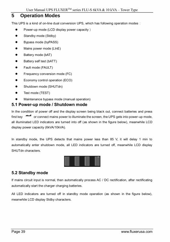
In standby mode, the UPS detects that mains power less than 85 V, it will delay 1 min to
automatically enter shutdown mode, all LED indicators are turned off, meanwhile LCD display
SHUTdn characters.
5.2 Standby mode
If mains circuit input is normal, then automatically process AC / DC rectification, after rectificating
automatically start the charger charging batteries.
All LED indicators are turned off in standby mode operation (as shown in the figure below),
meanwhile LCD display Stdby characters.

User Manual UPS FLUXERTM series FLU-S 6kVA & 10 kVA – Tower Type
Page 40 www.fluxerusa.com
There are several situations as follows to enter standby mode:
Bypass is abnormal after the UPS is powered up (including frequency conversion enable) and
the UPS isn’t turned on.
In mains power mode / battery mode / frequency conversion mode, shut down the UPS when
bypass is abnormal.
Shut down the single UPS unit when inverter of parallel UPS units is operating.
Exit fault mode and byass is abnormal.
5.3 Bypass mode
In bypass mode, mains power of bypass input goes through the filter to the load. If mains circuit
input is normal, then automatically process AC / DC rectification, after rectificating automatically
start the charger charging batteries.
LED indicator in bypass mode is as shown in the figure below (white color indicates illuminated
status), meanwhile LCD display byPASS characters.
There are three situations as follows to enter bypass mode:
Bypass is abnormal after the UPS is powered up (frequency conversion disable) and the UPS
isn’t turned on.
Shut down in mains power mode, overload or overtemperature.
Exit fault mode and bypass are normal.
When bypass is normal, turn off the UPS or the inverter circuit has failure, the UPS transfer to
bypass mode to supply uninterruptible power to the load.
Note:
Bypass mode doesn’t have function of backup.
5.4 Mains power mode (Frequency conversion mode)
In mains power mode, the mains power from mains circuit input supply AC power to the UPS
rectification, and supply DC power to the inverter circuit after PFC power factor correction, and then
supply uninterruptible AC power to the load via the inverter circuit. After the inverter startup,
automatically start the charger charging batteries.
LED indicator in mains power mode is as shown in the figure below: the inverter LED indicator
(green) is illuminated, meanwhile LCD display LinE characters.
User Manual UPS FLUXERTM series FLU-S 6kVA & 10 kVA – Tower Type
Page 41 www.fluxerusa.com
Note:
The inverter output frequency in frequency conversion mode is configured output frequency
and cutting off bypass is necessary; the inverter output frequency in mains power mode is
related to bypass frequency (the default is 50 Hz when bypass is abnormal and frequency
conversion disenable). Please contact with supplier or after sales staff if need to set frequency
conversion mode.
5.5 Battery mode / battery self test mode
In battery mode, the batteries go through DC / DC boost and supply DC voltage to the inverter, and
then supply AC power to the load via the inverter circuit.
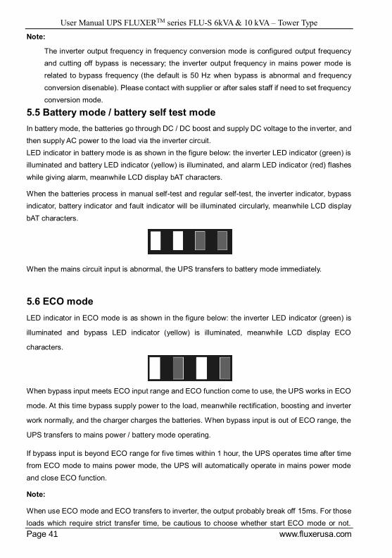
LED indicator in battery mode is as shown in the figure below: the inverter LED indicator (green) is
illuminated and battery LED indicator (yellow) is illuminated, and alarm LED indicator (red) flashes
while giving alarm, meanwhile LCD display bAT characters.
When the batteries process in manual self-test and regular self-test, the inverter indicator, bypass
indicator, battery indicator and fault indicator will be illuminated circularly, meanwhile LCD display
bAT characters.
When the mains circuit input is abnormal, the UPS transfers to battery mode immediately.
5.6 ECO mode
LED indicator in ECO mode is as shown in the figure below: the inverter LED indicator (green) is
illuminated and bypass LED indicator (yellow) is illuminated, meanwhile LCD display ECO
characters.
When bypass input meets ECO input range and ECO function come to use, the UPS works in ECO
mode. At this time bypass supply power to the load, meanwhile rectification, boosting and inverter
work normally, and the charger charges the batteries. When bypass input is out of ECO range, the
UPS transfers to mains power / battery mode operating.
If bypass input is beyond ECO range for five times within 1 hour, the UPS operates time after time
from ECO mode to mains power mode, the UPS will automatically operate in mains power mode
and close ECO function.
Note:
When use ECO mode and ECO transfers to inverter, the output probably break off 15ms. For those
loads which require strict transfer time, be cautious to choose whether start ECO mode or not.
User Manual UPS FLUXERTM series FLU-S 6kVA & 10 kVA – Tower Type
Page 42 www.fluxerusa.com
Please contact with supplier or after sales staff if need to set economy control operation.
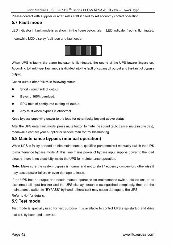
5.7 Fault mode
LED indicator in fault mode is as shown in the figure below: alarm LED Indicator (red) is illuminated,
meanwhile LCD display fault icon and fault code.
When UPS is faulty, the alarm indicator is illuminated, the sound of the UPS buzzer lingers on.
According to fault type, fault mode is divided into the fault of cutting off output and the fault of bypass
output.
Cut off output after failure in following status:
Short circuit fault of output.
Beyond 165% overload.
EPO fault of configured cutting off output.
Any fault when bypass is abnormal.
Keep bypass supplying power to the load for other faults beyond above status.
After the UPS enter fault mode, press mute button to mute the sound (auto cancel mute in one day),
meanwhile contact your supplier or service man for troubleshooting.
5.8 Maintenance bypass (manual operation)
When UPS is faulty or need on-site maintenance, qualified personnel will manually switch the UPS
to maintenance bypass mode. At this time mains power of bypass input supplys power to the load
directly, there is no electricity inside the UPS for maintenance operation.
Note: Make sure the system bypass is normal and not to start frequency conversion, otherwise it
may cause power failure or even damage to loads.
If the UPS has no output and needs manual operation on maintenance switch, please ensure to
disconnect all input breaker and the UPS display screen is extinguished completely, then put the
maintenance switch to “BYPASS” by hand, otherwise it may cause damage to the UPS.
Refer to 4.4 for details.
5.9 Test mode
Test mode is specially used for test purpose, It is available to control UPS step-startup and drive
test ect. by back-end software.

User Manual UPS FLUXERTM series FLU-S 6kVA & 10 kVA – Tower Type
Page 43 www.fluxerusa.com
6 Troubleshooting
LCD display in fault mode is as shown below:
Fault code informing:
Fault code Fault name Solutions
00 - 19 Bus voltage is abnormal Please contact your supplier.
20 - 34 Inverter voltage is abnormal Please contact your supplier.
35 - 39 Bus discharge fail (reserved) /
40 - 44 Overheat
Ensure that UPS is not
overloaded, and vent is not
blocked. Wait 10 minutes to let
UPS cool if the room temperature
is too high, and then restart it. If it
fails, contact your supplier.
45 - 49 Output short-circuits
Turn off UPS, remove all loads,
and make sure that the load has
no fault or internal short circuit.
Restart UPS, if it fails, contact
your supplier.
50 - 54 Overload
Check load capacity and
remove non-critical devices;
recalculate load power and reduce
the load quantity connected to UPS.
Check whether the load device faults
or not.
55 - 59 Negative power fault Please contact your supplier.
60 - 64 Shutdown fault
Check whether power source input
and output are normal or not, if not,
contact your supplier.
65 - 69 Parallel Software version conflict
(reserved) /
70 - 74 Synchronize signal loss(reserved) /
75 - 79 Synchronize pulse loss Check the wire connection of parallel
machine or contact your supplier.
Fault icon
Fault code
Fault mode
User Manual UPS FLUXERTM series FLU-S 6kVA & 10 kVA – Tower Type
Page 44 www.fluxerusa.com
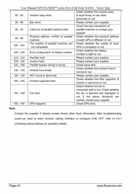
80 - 84 Inverter relay short
Check whether the inverter relay
is stuck firmly or has other
abnormity or not.
85 - 89 Bus short Please contact your supplier.
90 - 94 CAN bus of parallel machine fault
Check the wire connection of
parallel machine or contact your
supplier.
95 - 99 Physical address conflict of parallel
machine
Check whether the physical address
of each UPS is different or not.
100 - 104 The models of parallel machine are
not compatible
Check whether the model of each
UPS is consistent or not.
105 - 109 Error configuration of battery number Check whether the battery
number is right or not.
110 - 119 Rectifier fault Please contact your supplier.
120 - 124 Inverter fault Please contact your supplier.
125 - 129 Parallel bypass wiring is wrong Check input wire.
130 - 134 Inverter fuse break Check whether the inverter fuse is
normal or not.
135 - 139 PFC circuit is abnormal Please contact your supplier.
140 - 144 Inverter capacitor fault Check whether the filter capacitor of
inverter is abnormal or not.
145 - 149 Fan fault
Check whether the fan is
connected well or not. Check whether
the fan is blocked and damaged or
not; if the above situations are
normal, contact your supplier.
150 - 154 EPO happens Check EPO wire.
Note:
Contact the supplier if display screen shows other fault information. After troubleshooting,
power-up need to enter function setting interface to configure CHE OFF, refer to 4.6.1
(Checking status setting) for operation details.
User Manual UPS FLUXERTM series FLU-S 6kVA & 10 kVA – Tower Type
Page 45 www.fluxerusa.com
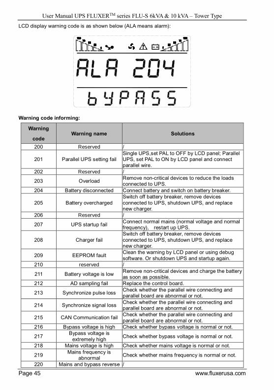
LCD display warning code is as shown below (ALA means alarm):
Warning code informing:
Warning
code Warning name Solutions
200 Reserved /
201 Parallel UPS setting fail Single UPS,set PAL to OFF by LCD panel; Parallel UPS, set PAL to ON by LCD panel and connect parallel wire.
202 Reserved /
203 Overload Remove non-critical devices to reduce the loads connected to UPS.
204 Battery disconnected Connect battery and switch on battery breaker.
205 Battery overcharged
Switch off battery breaker, remove devices
connected to UPS, shutdown UPS, and replace new charger.
206 Reserved /
207 UPS startup fail Connect normal mains (normal voltage and normal frequency), restart up UPS.
208 Charger fail
Switch off battery breaker, remove devices
connected to UPS, shutdown UPS, and replace new charger.
209 EEPROM fault Clean the warning by LCD panel or using debug
software. Or shutdown UPS and startup again.
210 reserved /
211 Battery voltage is low Remove non-critical devices and charge the battery as soon as possible.
212 AD sampling fail Replace the control board.
213 Synchronize pulse loss Check whether the parallel wire connecting and parallel board are abnormal or not.
214 Synchronize signal loss Check whether the parallel wire connecting and parallel board are abnormal or not.
215 CAN Communication fail Check whether the parallel wire connecting and
parallel board are abnormal or not.
216 Bypass voltage is high Check whether bypass voltage is normal or not.
217 Bypass voltage is
extremely high Check whether bypass voltage is normal or not.
218 Mains voltage is high Check whether mains voltage is normal or not.
219 Mains frequency is
abnormal Check whether mains frequency is normal or not.
220 Mains and bypass reverse /
User Manual UPS FLUXERTM series FLU-S 6kVA & 10 kVA – Tower Type
Page 46 www.fluxerusa.com
sequence(reserved)
221 Reserved /
222 End of discharge Charge the battery as soon as possible.
223 Inverter capacitor fault Check whether the filter capacitor of inverter is
abnormal or not.
224 Forbid startup UPS Check whether mains voltage and frequency is normal or not.
225 Reserved /
226 Reserved /
227 Reserved /
228 Reserved /
229 Reserved /
230 Reserved /
231 Reserved /
232 PFC fault Shutdown UPS, check the input fuse and battery fuse.
233 Reserved /
234 Mains voltage and
frequency is abnormal
Check whether mains voltage and frequency is
normal or not.
235 Bypass voltage and
frequency is abnormal Check whether bypass voltage and frequency is normal or not.
236 Bypass frequency is
abnormal Check whether bypass frequency is normal or not.
237 Output voltage is
abnormal(reserved) /
238 Battery voltage is
abnormal(reserved) /
239 ECO mode instable Clean the warning by LCD panel or using debug software. When mains and bypass are normal, set
ECO enable.
240 Load instable(reserved) /
241 Maintenance bypass mode Fix the maintenance bypass baffle.
242 Over Temperature often Clean the warning by LCD panel or using debug software, or startup UPS to clean the warning.
(Insure to find the reason of over temperature)
243 Parallel UPS, battery number is different
Set battery number by LCD panel again.
244 Battery temperature
compensation is abnormal(reserved)
/
245 Bypass voltage
instable(reserved) /
246 Test mode enable You can cancel TEST MODE using debug software.
247 Overload often Clean the warning by LCD panel or using debug software, or startup UPS to clean the warning.
(Insure to find the reason of overload.)