user network interface dsl
TRANSCRIPT

This document does not form part of any Wholesale Broadband Agreement or any Standard Form of
Access Agreement for the purposes of Part XIC of the Competition and Consumer Act 2010 and does
not vary any rights or obligations of a party under a Wholesale Broadband Agreement.
User Network Interface –
DSL Network Interface Specification

© 2020 nbn co limited | ABN 86 136 533 741 Page 2 of 27
Network Interface Specification – UNI-DSL Uncontrolled when printed
User Network Interface –
DSL Network Interface Specification
Version Description Effective Date
4.0 First issued version of WBA 4 1 December 2020
Copyright
This document is subject to copyright and must not be used except as permitted below or under the Copyright Act 1968 (Cth).
You must not reproduce or publish this document in whole or in part for commercial gain without the prior written consent of
nbn. You may reproduce and publish this document in whole or in part for educational or non-commercial purposes as
approved by nbn in writing.
Copyright © 2020 nbn co limited. All rights reserved. Not for general distribution.
Disclaimer
This document is provided for information purposes only. The recipient must not use this document other than with the consent
of nbn and must make its own inquiries as to the currency, accuracy and completeness of this document and the information
contained in it. The contents of this document should not be relied upon as representing nbn’s final position on the subject
matter of this document, except where stated otherwise. Any requirements of nbn or views expressed by nbn in this document
may change as a consequence of nbn finalising formal technical specifications, or legislative and regulatory developments.
Environment
nbn asks that you consider the environment before printing this document.

© 2020 nbn co limited | ABN 86 136 533 741 Page 3 of 27
Network Interface Specification – UNI-DSL Uncontrolled when printed
Contents 1 About this document ................................................................................................................. 5
1.1 Classification of network attributes ........................................................................................... 5
1.2 Status .......................................................................................................................................... 6
2 UNI-DSL – Physical Interface ...................................................................................................... 7
2.1 UNI-DSL Interface Modes ........................................................................................................... 7
2.2 Modem Compatibility / Registration .......................................................................................... 7
2.3 UNI-DSL Specification ................................................................................................................. 8
2.3.1 DSLAM Chipset and Firmware .......................................................................................... 8
2.3.2 DSL and OAM Features ..................................................................................................... 8
2.3.3 Modem Performance Requirements .............................................................................. 14
2.3.4 Minimum Modem Quality Standards ............................................................................. 15
2.3.4.1 TR-114 Pass Criteria ............................................................................................... 15
2.3.4.2 TR-249 Pass Criteria ............................................................................................... 16
2.4 Central Splitter / Filter .............................................................................................................. 17
2.5 Ethernet frame support ............................................................................................................ 17
3 UNI-DSL Ethernet Frame .......................................................................................................... 18
3.1 Frame Format ........................................................................................................................... 18
3.2 MAC Address Limitations ......................................................................................................... 18
3.3 UNI-DSL Addressing Modes ...................................................................................................... 19
3.4 Frame Tagging – VLAN Structure .............................................................................................. 20
3.4.1 Tag Protocol Identifier (TPID) Formats ........................................................................... 21
3.4.2 EtherType ........................................................................................................................ 21
3.5 Frame Addressing – Frame Forwarding.................................................................................... 22
3.6 Frames Size – Maximum Layer 2 Frame Size5F5F5F5F ........................................................... 23
4 Class of Service (CoS) ............................................................................................................... 25
4.1 Priority Identification ................................................................................................................ 25
4.2 Priority Encoding (Ingress) and Decoding (Egress) ................................................................... 25
4.2.1 Unmarked (Default-Mapped) ......................................................................................... 25
4.2.2 DSCP (DSCP-Mapped) ..................................................................................................... 26

© 2020 nbn co limited | ABN 86 136 533 741 Page 4 of 27
Network Interface Specification – UNI-DSL Uncontrolled when printed
4.2.3 PCP (Priority-Tagged and Tagged) .................................................................................. 26
Figures
Figure 1: Untagged and Single-Tagged Ethernet Frames ..................................................................... 18
Figure 2: C-Tag Structure (4 Bytes) ....................................................................................................... 20
Figure 3: Definition of Maximum Layer 2 Frame Size (UNI-DSL, Default-Mapped and DSCP-Mapped
Mode) .................................................................................................................................................... 23
Figure 4: Definition of Maximum Layer 2 Frame Size (UNI-DSL, Priority-Tagged and Tagged Mode) . 23
Tables
Table 1: Mandatory DSL and OAM Features ........................................................................................... 8
Table 2: Modem VDSL Performance Requirements0F0F0F0F ............................................................ 15
Table 3: Summary of minimum modem quality standard tests ........................................................... 15
Table 4: 15.1 Rate adaptive performance tests for BA17ade with DPBO and UPBO, retransmission
disabled. ................................................................................................................................................ 16
Table 5: 15.2 Rate adaptive performance tests for BA17ade with DPBO and UPBO, retransmission
enabled ................................................................................................................................................. 16
Table 6: TR-249 Pass Criteria ................................................................................................................ 17
Table 7: AVC Addressing Modes at the UNI-DSL................................................................................... 19
Table 8: C-Tag C-VID Requirement at the UNI-DSL ............................................................................... 20
Table 9: TPID (UNI-DSL) Requirements ................................................................................................. 21
Table 10: Supported EtherType on a Tagged Ethernet frame .............................................................. 21
Table 11: UNI-DSL Frame Forwarding Details ....................................................................................... 22
Table 12: Layer 2 Maximum Frame Size for nbn™ Ethernet (FTTB) and nbn™ Ethernet (FTTN) .......... 24
Table 13: UNI-DSL Addressing Mode Marking Scheme ........................................................................ 25
Table 14: DSCP Setting for UNI-DSL DSCP-Mapped Addressing Mode ................................................. 26
Table 15: PCP Setting for UNI-DSL DSCP-Mapped Addressing Mode ................................................... 27

© 2020 nbn co limited | ABN 86 136 533 741 Page 5 of 27
Network Interface Specification – UNI-DSL Uncontrolled when printed
1 About this document In this document:
• Major Attributes are identified with a thick red border;
• Minor Attributes are identified with a thick blue border;
• Major and Minor Attributes in tables are identified by an associated cell within the table marked as either Major or Minor;
• Important information is identified with a thin black border with gold background and prefixed with the word “Important”;
and
• all other attributes are Unsupported Attributes.
Any feature, parameter and/or behaviour of nbn™ Infrastructure which is not included in a Network
Interface Specification is an Unsupported Attribute.
1.1 Classification of network attributes
nbn may, in its absolute discretion, identify or re-classify any attribute of the nbn™ Network in
accordance with clause C13.5(a) of the Head Terms. Each attribute of the nbn™ Network may be
classified as one of the following:
Classification Description
Major A Supported Attribute necessary for using a Product. Customer is expected to make use of the attribute as an input into Customer Products.
Any Upgrade to such an attribute is anticipated to:
• require Customer to take particular action to continue to use a Product after the implementation of the Upgrade;
• result in a Product no longer being supplied by reason of the Upgrade; or
• require Customer to commit material capital expenditure in response to implementation of that Upgrade.
Minor A Supported Attribute necessary for using a Product. Customer is expected to make use of the attribute as an input into Customer Products.
However, any Upgrade to such an attribute is not anticipated to be a Major Upgrade.
Unsupported An attribute that is not a Supported Attribute and which need not be relied upon to use a Product. Customer should be resilient to changes to such an attribute.

© 2020 nbn co limited | ABN 86 136 533 741 Page 6 of 27
Network Interface Specification – UNI-DSL Uncontrolled when printed
Classification Description
Customer should not assume or rely upon specific network behaviour in connection with such attributes. Customer should consider these facts when connecting to any nbn™ Infrastructure, using a Product and constructing, configuring and supplying Customer Products.
The network attribute descriptions above do not define the Upgrade process that will apply in
respect of Upgrades to those attributes. For that information, see clauses C13 and C17 of the Head
Terms.
Customer must not rely on the currency of the descriptions of any Unsupported Attributes in any
Network Interface Specification, which may change with limited or no notice or update to the
Network Interface Specification.
Important information is provided to Customer where this information relates to how a Customer
network must be configured to use a Product or where failure to observe a limitation will result in
the Product not performing to specification.
1.2 Status
This document does not form part of any Wholesale Broadband Agreement or any Standard Form of
Access Agreement for the purposes of Part XIC of the Competition and Consumer Act 2010 and does
not vary any rights or obligations of a party under a Wholesale Broadband Agreement.
This document refers to and is to be read subject to the terms of the nbn™ Ethernet Product Module
of the Wholesale Broadband Agreement.

© 2020 nbn co limited | ABN 86 136 533 741 Page 7 of 27
Network Interface Specification – UNI-DSL Uncontrolled when printed
2 UNI-DSL – Physical Interface
2.1 UNI-DSL Interface Modes
Section 4.1(a) of the nbn™ Ethernet Product Description and section 3.3 of the nbn™ Ethernet
Product Technical Specification outline the product attributes of the UNI-DSL Product Component,
including that the UNI-DSL is a VDSL2 interface in alignment with ITU-T G.993.2 (01/ 15) and
supporting standards.
For UNI-DSL services it is Customer's responsibility to provide a VDSL2 modem, as outlined in section
2.2.
2.2 Modem Compatibility / Registration
Important:
The registration process consists of a self-certification, executed by Customer, followed by a
registration of the self-certification by Customer to nbn. To register Modem, Customer must supply
the Modem Vendor ID, System ID and Version Number as described in ITU-T G.993.2 section
11.2.3.6, as well as a clear-text name uniquely identifying the combination of hardware and
firmware to be entered into the registration database.
Customer must not register Modem, unless:
• the Modem and its firmware supports all applicable mandatory ITU-T requirements for vectored
VDSL2 and nbn UNI-DSL specifications referenced below;
• the Modem and its firmware has been tested successfully against every feature of the nbn UNI-
DSL Specification outlined in section 2.3; and
• upon request, Customer can provide evidence that the above requirements are met.
Where Customer updates Modem hardware or firmware which impacts VDSL components or VDSL
drivers, re-certification and re-registration for the new hardware and firmware combination is
required.
Irrespective of whether Modem is registered, where specific Modem or a certain model and/or
firmware of Modem is causing (or nbn reasonably considers that it is likely to cause) detriment to
other services, nbn may:
• remove the Modem from the Modem registration list;
• place an Ordered Product using that Modem into a Repair Profile; and/or
• Suspend an Ordered Product using that Modem in accordance with the Head Terms.

© 2020 nbn co limited | ABN 86 136 533 741 Page 8 of 27
Network Interface Specification – UNI-DSL Uncontrolled when printed
2.3 UNI-DSL Specification
For the purposes of Modem self-certification by Customer, nbn will maintain a specification of the
UNI-DSL interface comprised of three separate sections:
• a DSLAM chipset and firmware list;
• a list of mandatory DSL and OAM Features that the Modem must support; and
• a minimum rate-reach performance specification that the Modem must achieve.
Important: These specifications will be updated regularly and it is the responsibility of Customer to
source Modem hardware and firmware updates to maintain compatibility.
2.3.1 DSLAM Chipset and Firmware
Important: The nbn™ Equipment, used in connection with nbn™ Ethernet (FTTB) and nbn™ Ethernet
(FTTN), utilises chipsets to provide UNI-DSL services. Modem hardware and firmware intended for
use with the UNI-DSL must support full vectored interoperability with all of the DSLAM chipsets and
firmware combinations that nbn notifies Customer from time to time.
2.3.2 DSL and OAM Features
The UNI-DSL will utilise the DSL features listed below. Modem hardware and firmware intended for
use with the UNI-DSL must be able to demonstrate compatibility with all of the requirements listed:
Table 1: Mandatory DSL and OAM Features
ID Requirement Standard References Classification Comment
1 All mandatory
vectoring related
functionality
(excluding tests 8.1,
8.5, 8.7)1
ITU-T G.993.5 (01/
15), BBF TR-249
Issue 1
Major Crosstalk / FEXT
reduction, substantial bit
rate and stability
improvements
2 G.inp ITU-T G.998.4, BBF
TR-115 Issue2
section 5.2. Test
setup is intended for
FEC testing - only
200us noise burst
and some test
adaptation required
Minor Improved impulse noise
protection with respect to
I-FEC approach, improving
end user experience and
throughput under
conditions of impulse
noise.
1 These excluded tests now form part of Minimum Modem Quality Standards as described in section 2.3.4 of this Network Interface
Specification.

© 2020 nbn co limited | ABN 86 136 533 741 Page 9 of 27
Network Interface Specification – UNI-DSL Uncontrolled when printed
ID Requirement Standard References Classification Comment
Support for on-line
reconfiguration
(OLR) specifically bit
swapping and
Seamless Rate
Adaptation
ITU-T G.998.4
Amendment 1, BBF
TR-115 Issue2
section 5.4
Minor Improved stability. Higher
throughput. Faster
recovery when conditions
change
Intra-DTU
interleaver,
extended memory
for Enhanced Net
Data Rates with
Vectoring, and
Improved ATTNDR
calculation methods
ITU-T G.998.4
Amendment 2
Minor Further stability,
throughput, recovery
improvements
3 Seamless Rate
Adaptation (SRA)
ITU-T G.993.2, BBF
TR-115 Issue 2
section 5.4.3
Minor Maximises throughput
during showtime, and
improves stability under
slowly varying noise
conditions
4
Requirements 1 to 3 of
this table supported in
both upstream and
downstream directions.
Some VDSL2 chipsets do
not support G.inp in the
upstream direction at this
time.
5 Requirements 1 to 4
of this table useable
simultaneously
without restriction
Not acceptable that the
listed capabilities are
usable only separately, or
are encumbered by
restrictions regarding
simultaneous use
6 Error(f) packets sent
over layer 2
backchannel
ITU-T G.993.5
section 7.4.1
Minor G.993.5 section 7.4.2
describes an alternative
Error(f) technique but
section 7.4.1 method will
be deployed due to

© 2020 nbn co limited | ABN 86 136 533 741 Page 10 of 27
Network Interface Specification – UNI-DSL Uncontrolled when printed
ID Requirement Standard References Classification Comment
shortcomings of the
alternate method.
7 Modem prioritises
processing of
Error(f) packets
even in condition of
end user traffic
congestion or other
overload
Minor Necessary for satisfactory
operation of vectoring
8 Support for orderly
and disorderly shut-
down (within 10ms)
events
ITU-T G.993.5
section 9
Minor Stability of neighbouring
lines, stability of
neighbouring vectored
lines
9 Protection against
single wire
connections and
disorderly leaving
events in the
upstream direction
(e.g. when cable is
cut)
BBF TR-249 section
9.4 (single wire
interruption test)
Minor Modem must pass this
test, interrupting
upstream transmissions
promptly upon detection
of changes or interruption
in the downstream
received signal
10 Monitored tones /
sub-carriers
ITU-T G.993.2,
sections 3.36,
10.3.3.1, 10.3.4.4,
BBF TR-115 Issue 2
section 5.4.1, + Issue
2 Amendment 1
section 5.4.5, + need
to add a bit loading
recovery test
Minor Support for monitor
tones, and recovery of
tones with zero bit loading
to a non-zero bit loading
11 Alternative Electrical
Length Estimation
Method (AELEM)
ITU-T G.993.2
Amendment 7
Minor Reduces loop length
estimation errors in
presence of bridged taps.
Reduced impact on
neighbouring lines in
presence of bridged taps,

© 2020 nbn co limited | ABN 86 136 533 741 Page 11 of 27
Network Interface Specification – UNI-DSL Uncontrolled when printed
ID Requirement Standard References Classification Comment
particularly when
operating unvectored.
12 Inventory
identification
request supported
and returns valid
and unique
responses for
Modem and Chipset
Vendor ID and
version
ITU-T G.993.2 sect
11.2.3.6, G.994.1,
G.997.1 sects 7.4.2,
7.4.4, 7.4.6, 7.4.8,
and BBF ITU-T TR-
115
Minor Unique and valid
responses required for
both Modem vendor ID
and firmware version
number, plus Chipset
vendor ID and firmware
version number - so that
Modem and its chipset
can be uniquely identified
both in terms of HW and
firmware
13 Reporting of valid H-
log in all parts of
spectrum, with and
without
DPBO/UPBO applied
in that part of
spectrum
ITU-T G.993.2
section 11.4.1
Minor Some Modem reports
false H-log and other
tone/spectrum data in
parts of spectrum where
power backoff applied.
Reporting of valid
TxPSD in all parts of
spectrum, with and
without
DPBO/UPBO applied
in that part of
spectrum
Minor
Reporting of valid
QLN in all parts of
spectrum
Minor
Reporting of valid
SNR in all parts of
spectrum, with and
without
DPBO/UPBO applied
Minor

© 2020 nbn co limited | ABN 86 136 533 741 Page 12 of 27
Network Interface Specification – UNI-DSL Uncontrolled when printed
ID Requirement Standard References Classification Comment
in that part of
spectrum
14 US0 band ITU-T G.993.2 Minor Support for US0 is critical
to the operation of
assurance activities in
connection with the
remediation of loop
impairments such as
bridged taps.
15 B8-11 profile ITU-T G.993.2 Major
B8- 17 profile is
desired
ITU-T G.993.2 Minor
16 Virtual noise ITU-T G.993.2
section 11.4.1
Minor Improved stability and
throughput in presence of
Time Of Day dependent or
varying noise environment
17 DELT loop
diagnostics mode
Minor
18 Different delay and
INP settings for each
direction
Minor
19 Upstream and
Downstream Power
Backoff must be
supported
ITU-T G.993.2, ITU-T
G.997.1
Major
20 Use of at least 16
RFI band notches
simultaneously
Minor
21 Robust Overhead
Channel (ROC)
ITU-T G.993.2
section 9.5.3.1
Minor Improves stability in harsh
conditions
22 Support for
autonomous
transmission of
ITU-T G.997.1
section 7.1.1.1.3,
BBF TR-115 Issue 2
Minor Assist determination of
the cause of intermittent
service issues

© 2020 nbn co limited | ABN 86 136 533 741 Page 13 of 27
Network Interface Specification – UNI-DSL Uncontrolled when printed
ID Requirement Standard References Classification Comment
Loss-Of-Power (LPR)
message
Amendment 1
section 5.10
23 Downstream
Frequency
Dependent Pilot
Sequence (FDPS)
ITU-T G.993.5
Amendment 1
section 7.2
Minor Reduces initialisation time
when entering a vectoring
group
Upstream
Frequency
Dependent Pilot
Sequence (FDPS)
ITU-T G.993.5
Amendment 1
section 7.3.3
Minor
24 BER no greater than
1E-10 with 6dB
noise margin, no
impulse noise, in
both fast and
interleaved modes
BBF TR-114 Issue 2
section 8.1 and 8.2
Table 23
Minor Modem PHY capable of
supporting a higher layer
service that can achieve a
basic / repeatable end to
end SLA
BER no greater than
1E-7 with 0dB noise
margin, no impulse
noise, in both fast
and interleaved
modes
Minor
25 Sufficient memory
and processing
resources to sustain
100 Mbit/s (Layer 2)
across the UNI-DSL
port in the
downstream
direction, in
presence of
correctable REIN
and SHINE with
G.inp active
Minor Must be simultaneous
with upstream sustained
traffic requirement
Sufficient memory
and processing
resources to sustain
40 Mbit/s (Layer 2)
Minor
© 2020 nbn co limited | ABN 86 136 533 741 Page 14 of 27
Network Interface Specification – UNI-DSL Uncontrolled when printed
ID Requirement Standard References Classification Comment
across the UNI-DSL
port in the
upstream direction,
in presence of
correctable REIN
and SHINE with
G.inp active
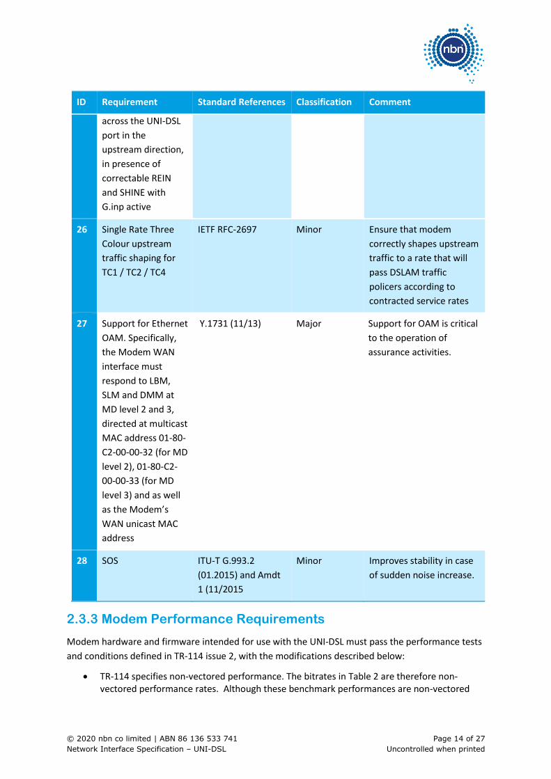
26 Single Rate Three
Colour upstream
traffic shaping for
TC1 / TC2 / TC4
IETF RFC-2697 Minor Ensure that modem
correctly shapes upstream
traffic to a rate that will
pass DSLAM traffic
policers according to
contracted service rates
27 Support for Ethernet
OAM. Specifically,
the Modem WAN
interface must
respond to LBM,
SLM and DMM at
MD level 2 and 3,
directed at multicast
MAC address 01-80-
C2-00-00-32 (for MD
level 2), 01-80-C2-
00-00-33 (for MD
level 3) and as well
as the Modem’s
WAN unicast MAC
address
Y.1731 (11/13) Major Support for OAM is critical
to the operation of
assurance activities.
28 SOS ITU-T G.993.2
(01.2015) and Amdt
1 (11/2015
Minor Improves stability in case
of sudden noise increase.
2.3.3 Modem Performance Requirements
Modem hardware and firmware intended for use with the UNI-DSL must pass the performance tests
and conditions defined in TR-114 issue 2, with the modifications described below:
• TR-114 specifies non-vectored performance. The bitrates in Table 2 are therefore non-vectored performance rates. Although these benchmark performances are non-vectored

© 2020 nbn co limited | ABN 86 136 533 741 Page 15 of 27
Network Interface Specification – UNI-DSL Uncontrolled when printed
rates, nbn’s network requires all Modem hardware to support and interoperate correctly with nbn’s vectoring implementation.
• TR-114 does not cover the band plan and TxPSD masks that nbn is deploying in its FTTB Network and FTTN Network footprints. When performing TR-114 tests, DSLAMs and modems should be configured in Fast Path mode, with the 998ADE17-M2x-A masks and band plan (also known as B8-11). The benchmark results below assume this band plan and Fast Path mode. Testing should otherwise be conducted in accordance with TR-114 998ADE17-M2x-B (B8-12) masks and band plan, and relevant G993.2 Annex B configurations and requirements.
Table 2: Modem VDSL Performance Requirements0F0F0F0F
2
Distance Minimum Net Data Rate Achieved
DS (B8-11 Fast mode)
Minimum Net Data Rate Achieved
US (B8-11 Fast mode)
150m 56,841 20,327
450m 36,382 14,346
1050m 16,449 1,956
1500 m 8,789 540
2.3.4 Minimum Modem Quality Standards
Important: All Modems must at a minimum comply with sections 2.3.1, 2.3.2 and 2.3.3 above.
To comply with the Minimum Modem Quality Standards the following test criteria in this section
2.3.4 must be met or exceeded.
Table 3: Summary of minimum modem quality standard tests
Broadband
Forum
Issue Amendment Standard Name Tests
TR-114 3 4 VDSL2 Performance Test Plan 15.1, 15.2
TR-249 1 1 Testing of G.993.2 Self-FEXT
Cancellation (vectoring)
8.1, 8.5, 8.7
2.3.4.1 TR-114 Pass Criteria
Tests conducted using BA17ade profile and nbn line card.
2 Performance requirements as per TR114 Issue 2, November 2012.

© 2020 nbn co limited | ABN 86 136 533 741 Page 16 of 27
Network Interface Specification – UNI-DSL Uncontrolled when printed
Table 4: 15.1 Rate adaptive performance tests for BA17ade with DPBO and UPBO, retransmission
disabled.
Loop Length (metres) Downstream
(kbps)
Upstream
(kbps)
150 46,600 15,400
450 39,800 11,400
1,050 25,100 3,900
1,200 21,400 3,800
1,500 14,500 1,500
Table 5: 15.2 Rate adaptive performance tests for BA17ade with DPBO and UPBO, retransmission
enabled
Loop Length (metres) Downstream
(kbps)
Upstream
(kbps)
150 56,403 20,080
450 41,437 14,726
1,050 24,178 4,992
1,200 21,004 4,271
1,500 14,167 1,845
2.3.4.2 TR-249 Pass Criteria
Test conducted using BA17ade profile, nbn line and vectoring card and nbn cable.

© 2020 nbn co limited | ABN 86 136 533 741 Page 17 of 27
Network Interface Specification – UNI-DSL Uncontrolled when printed
Table 6: TR-249 Pass Criteria
Test Pass criteria
8.1 Collocated Vectoring CPEs Test Case Expected Results listed in TR-249(i1) 8.1.4
8.5 Non-Collocated Vectoring CPE Test
Case (3 loop lengths – referenced in
Table 17 - Loops used for Testing)
Expected Results listed in TR-249(i1) 8.5.4
8.7 Long Term Stability Test Case Expected Results listed in TR-249(i1) 8.7.4
2.4 Central Splitter / Filter
Important: Central Splitters (or Filters)1F1F1F1F
3 used in the Premises in conjunction with nbn™ Ethernet
(FTTB) and nbn™ Ethernet (FTTN) must comply with Australian Standard AS/CA S041.3:2015
“Requirements for DSL Customer Equipment for connection to the Public Switched Telephone
Network – Part 3: Filters for use in connection with all DSL services".
2.5 Ethernet frame support
Important: For UNI-DSL services Ethernet frames are supported using the Packet Transfer Mode and
64/65 Octet framing in accordance with ITU-T G.993.2 “L.3 Packet transmission convergence
function (PTM-TC)”
3 Also referred to as “Centralised Filter (Master Splitters)” within AS/CA S041.3:2015.

© 2020 nbn co limited | ABN 86 136 533 741 Page 18 of 27
Network Interface Specification – UNI-DSL Uncontrolled when printed
3 UNI-DSL Ethernet Frame
3.1 Frame Format
The nbn™ Ethernet implements untagged or single-tagged (C-Tag) Ethernet frames at the UNI-DSL as
defined in IEEE802.1ad and illustrated by the following figure.
Figure 1: Untagged and Single-Tagged Ethernet Frames
Important: The tag option implemented is selectable by Customer. For tagged traffic at ingress to
the UNI-DSL, any data following the first tag (C-Tag) will be assumed to be payload and will not be
used by the nbn™ Network to determine any action. This section of the frame may be used to
capture any type of additional tagging, and allow Customer to deliver a Customer Edge Virtual Local
Area Network (CE-VLAN) transparent service.4
3.2 MAC Address Limitations
Each UNI-DSL is capable of supporting up to eight simultaneous MAC source addresses.
Important: This imposes a limit on the number of Layer 2 devices that Customer may allow to
connect directly to each UNI-DSL. Any attempt to connect a number of devices directly to a UNI-DSL
that exceeds this limit will result in traffic from the newly-attached devices being discarded.
The nbn™ Network will learn the first eight MAC source addresses detected at ingress to the UNI-
DSL, based upon ingress service frames. A MAC address ageing function ensures that any obsolete
MAC addresses are removed from the active list, after a period of 300 seconds.
Note that this limitation applies for the UNI-DSL irrespective of the service type and does not imply
MAC address-based forwarding for unicast services based on 1:1 VLANs.
Customer should use a device that performs Layer 3 routing to interconnect to the UNI-DSL. If
Customer does not do so, Customer accepts the consequences of any issues arising from MAC
address restrictions.
4 Access Loop Identification functionality is not supported where Customer uses the relevant section of the frame to deliver a CE-VLAN
transparent service.

© 2020 nbn co limited | ABN 86 136 533 741 Page 19 of 27
Network Interface Specification – UNI-DSL Uncontrolled when printed
3.3 UNI-DSL Addressing Modes
The UNI-DSL supports four addressing modes for accessing AVCs, and indicating the priority of
service frames across the UNI-DSL:
• Default-Mapped
• DSCP-Mapped
• Priority-Tagged
• Tagged
These options for addressing services at the UNI-DSL are shown in Table 7.
Table 7: AVC Addressing Modes at the UNI-DSL
UNI-DSL Mode Maximum Number of AVCs addressable at UNI-DSL
Ability to communicate priority information across UNI-DSL?
Comments
Classification Minor Major
Default-Mapped 1 N
Untagged service frames that carry no Layer 2 priority information, as per IEEE802.3.
DSCP-Mapped 1 Y
Untagged service frames that carry no Layer 2 priority information, as per IEEE802.3, where priority information is encoded into the DSCP field, as per RFC2474 for both IPv4 and IPv6.
Priority-Tagged 1
Y
Service frames at the UNI-DSL that carry Layer 2 Priority Information in the VLAN tag, as per IEEE 802.1p, where priority information is encoded into the VLAN Priority-Code-Point (PCP) field.
Tagged 1 Y
The addressing mode must be specified at time of solution definition, and determines how Customer
interfaces to the AVC and UNI-DSL.5 These modes have no impact on the operation or allocation of
AVC C-TAGs at the NNI.
5 Note the limitations on addressing mode and AVC traffic class combinations tabled in Appendix A and Appendix B of the nbn™ Ethernet
Product Technical Specification.

© 2020 nbn co limited | ABN 86 136 533 741 Page 20 of 27
Network Interface Specification – UNI-DSL Uncontrolled when printed
3.4 Frame Tagging – VLAN Structure
Priority-Tagged and Tagged UNI-DSL Addressing Modes require the following single-tagged field.
Figure 2: C-Tag Structure (4 Bytes)
• C-TPID – Tag Protocol Identifier, used to identify the tag type
• C-PCP – Priority Code Point Identifier, used for priority marking
• S/C-CFI – Canonical Format Identifier, not used
• S/C-VID – VLAN Identifier, used for service identification
Priority-Tagged and Tagged UNI-DSL modes require Customer to specify a C-VID value. The valid
range of C-VID values is shown below in Table 8.
Table 8: C-Tag C-VID Requirement at the UNI-DSL
Interface Mode
nbn™ Network
Comment Classification
Default-Mapped
FTTB, FTTN
C-VID is not supported at the UNI for this mode. Major
DSCP-Mapped
FTTB, FTTN
C-VID is not supported at the UNI for this mode. Major
Priority-Tagged
FTTB, FTTN
In Priority-Tagged mode, a C-VID allocation of anything other than 0 or Null (unpopulated) may result in unsupported behaviours
Major
Tagged FTTB, FTTN
In Tagged mode C-VID allocations must match the C-VID specified by Customer at the time Customer orders the associated AVC.
C-VID allocations outside of the allowed range (2 – 4004) will result in frames being discarded.
Major
© 2020 nbn co limited | ABN 86 136 533 741 Page 21 of 27
Network Interface Specification – UNI-DSL Uncontrolled when printed
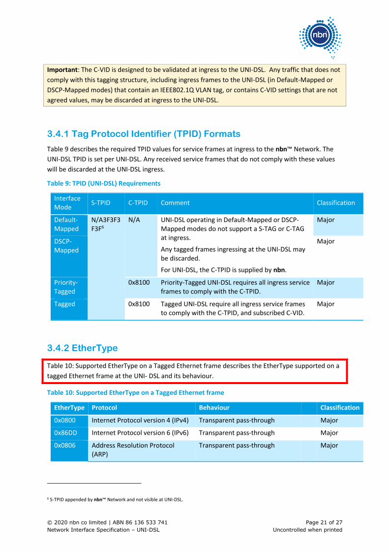
Important: The C-VID is designed to be validated at ingress to the UNI-DSL. Any traffic that does not
comply with this tagging structure, including ingress frames to the UNI-DSL (in Default-Mapped or
DSCP-Mapped modes) that contain an IEEE802.1Q VLAN tag, or contains C-VID settings that are not
agreed values, may be discarded at ingress to the UNI-DSL.
3.4.1 Tag Protocol Identifier (TPID) Formats
Table 9 describes the required TPID values for service frames at ingress to the nbn™ Network. The
UNI-DSL TPID is set per UNI-DSL. Any received service frames that do not comply with these values
will be discarded at the UNI-DSL ingress.
Table 9: TPID (UNI-DSL) Requirements
Interface Mode
S-TPID C-TPID Comment Classification
Default-Mapped
N/A3F3F3F3F6
N/A UNI-DSL operating in Default-Mapped or DSCP-Mapped modes do not support a S-TAG or C-TAG at ingress.
Any tagged frames ingressing at the UNI-DSL may
be discarded.
For UNI-DSL, the C-TPID is supplied by nbn.
Major
DSCP-Mapped
Major
Priority-Tagged
0x8100 Priority-Tagged UNI-DSL requires all ingress service frames to comply with the C-TPID.
Major
Tagged 0x8100 Tagged UNI-DSL require all ingress service frames to comply with the C-TPID, and subscribed C-VID.
Major
3.4.2 EtherType
Table 10: Supported EtherType on a Tagged Ethernet frame describes the EtherType supported on a
tagged Ethernet frame at the UNI- DSL and its behaviour.
Table 10: Supported EtherType on a Tagged Ethernet frame
EtherType Protocol Behaviour Classification
0x0800 Internet Protocol version 4 (IPv4) Transparent pass-through Major
0x86DD Internet Protocol version 6 (IPv6) Transparent pass-through Major
0x0806 Address Resolution Protocol (ARP)
Transparent pass-through Major
6 S-TPID appended by nbn™ Network and not visible at UNI-DSL.

© 2020 nbn co limited | ABN 86 136 533 741 Page 22 of 27
Network Interface Specification – UNI-DSL Uncontrolled when printed
EtherType Protocol Behaviour Classification
0x8863 PPPoE Discovery Stage Refer to Section 4.4 of Access Virtual Circuit
Network Interface Specification
Major
0x8864 PPPoE Session Stage Refer to Section 4.4 of Access Virtual Circuit
Network Interface Specification
Major
0x88A8 DHCPv4 Relay Agent Option 82 Refer to Section 4.3 of Access Virtual Circuit
Network Interface Specification
Major
0x88A8 DHCPv6 Relay Agent Option 18 Refer to Section 4.3 of Access Virtual Circuit
Network Interface Specification
Major
0x8847 Multi- Protocol Label Switching (MPLS) unicast
Transparent pass-through Major
0x8848 Multi- Protocol Label Switching (MPLS) multicast
Transparent pass-through Major
Important: Transparency of other EtherTypes has not been tested by nbn and are unsupported.
3.5 Frame Addressing – Frame Forwarding
The UNI-DSL implements forwarding of service frames as per IEEE802.1ad, section 8.6.
Table 11: UNI-DSL Frame Forwarding Details
Destination
MAC Address Application
Default Behaviour
Optional Configurable Behaviour
Classification
01-80-C2-00-00-00 Bridge Group Address Discard None Major
01-80-C2-00-00-01 IEEE Std 802.3 PAUSE Discard None Major
01-80-C2-00-00-02 LACP/LAMP Discard None Major
Link OAM Discard None Major
01-80-C2-00-00-03 IEEE Std. 802.1X PAE address
Discard None Major
01-80-C2-00-00-04 - 01-80-C2-00-00-0F
Reserved Discard None Major
01-80-C2-00-00-10 All LANs Bridge Management Group Address
Discard None Major
01-80-C2-00-00-20 GMRP Discard None Major

© 2020 nbn co limited | ABN 86 136 533 741 Page 23 of 27
Network Interface Specification – UNI-DSL Uncontrolled when printed
Destination
MAC Address Application
Default Behaviour
Optional Configurable Behaviour
Classification
01-80-C2-00-00-21 GVRP Discard None Major
01-80-C2-00-00-22 -
01-80-C2-00-00-2F
Reserved GARP
Application
addresses
Discard None Major
01-80-C2-00-00-30 -
01-80-C2-00-00-3F
CFM Tunnel4F4F4F4F7 None Major
Note the following definitions for the purposes of the above table:
• Discard – the service frame will be discarded at ingress to the nbn™ Network
• Tunnel – the service frame is passed to the AVC/CVC and carried through the nbn™ Network
3.6 Frames Size – Maximum Layer 2 Frame Size5F5F5F5F
8
Figure 3 depicts the definition of the maximum Layer 2 frame size at the UNI-DSL, highlighting the
exclusion of the S-TAG and C-TAG. Note that this example shows a UNI-DSL service frame using
either Default-Mapped or DSCP-Mapped modes.
Figure 3: Definition of Maximum Layer 2 Frame Size (UNI-DSL, Default-Mapped and DSCP-Mapped
Mode)
Figure 4 depicts the definition of the maximum Layer 2 frame size at the UNI-DSL, highlighting the
inclusion of the C-Tag as provided by Customer. Note that this example shows a UNI-DSL service
frame using either Priority-Tagged or Tagged modes.
Figure 4: Definition of Maximum Layer 2 Frame Size (UNI-DSL, Priority-Tagged and Tagged Mode)
7 Tunnelling supported for Maintenance Domains (MD) 4, 5, 6, 7.
8 This is also known as the Maximum Transmission Unit (MTU).

© 2020 nbn co limited | ABN 86 136 533 741 Page 24 of 27
Network Interface Specification – UNI-DSL Uncontrolled when printed
Table 12 describes the maximum and minimum Layer 2 frames sizes that will be accepted by the
nbn™ Network, taking into consideration the UNI-DSL Addressing Mode and type of nbn™ Network.
Table 12: Layer 2 Maximum Frame Size for nbn™ Ethernet (FTTB) and nbn™ Ethernet (FTTN)
Parameter FTTB/FTTN Classification
Maximum Layer 2 Frame Size at UNI-DSL (Default-Mapped or DSCP-Mapped)
1,592 Bytes Minor
Maximum Layer 2 Frame Size at UNI-DSL (Tagged or Priority-Tagged Mode)
1,596 Bytes Minor
Minimum Layer 2 Frame Size at the UNI-DSL (Default-Mapped or DSCP-Mapped Model)
64 Bytes Minor
Minimum Layer 2 Frame Size at UNI-DSL (Priority-Tagged or Tagged Mode)
68 Bytes Minor
Important: Frames that exceed frame size limits may be silently discarded. It is the responsibility of
the Customer to manage the frame size of their traffic before it enters the nbn™ Network.

© 2020 nbn co limited | ABN 86 136 533 741 Page 25 of 27
Network Interface Specification – UNI-DSL Uncontrolled when printed
4 Class of Service (CoS)
4.1 Priority Identification
The UNI-DSL supports the following marking scheme for the purpose of priority identification.
• Priority Code Point (PCP) as per IEEE802.1p is Supported as a Major
DiffServ Code Point (DSCP) as per RFC2474 is Unsupported
The marking scheme utilised depends on the UNI-DSL Addressing Mode selected as follows.
Table 13: UNI-DSL Addressing Mode Marking Scheme
UNI-DSL Address Mode Marking Scheme Classification
Default-Mapped Unmarked Major
DSCP-Mapped DSCP Major
Priority-Tagged PCP Major
Tagged PCP Major
Note that the DSCP priority marking for ingress traffic at the UNI-DSL is supported only for traffic
encapsulated as IP over Ethernet.
4.2 Priority Encoding (Ingress) and Decoding (Egress)
Important: Priority encoding and decoding interworking between the Customer Equipment and the
nbn™ Network at the UNI-DSL is dependent on the UNI-DSL Addressing Mode selected.
Customer will be required to specify all required UNI-DSL and NNI assignments during the on-
boarding phase for nbn™ Ethernet (FTTB) and nbn™ Ethernet (FTTN).
4.2.1 Unmarked (Default-Mapped)
In the case of Default-Mapped, Customer Equipment is not required to encode and decode priority
information at ingress to and egress from the UNI-DSL as the traffic is directly mapped to a
nominated traffic class within the nbn™ Network as specified by the relevant AVC Bandwidth Profile
tables in Appendix B to the nbn™ Ethernet Product Technical Specification.

© 2020 nbn co limited | ABN 86 136 533 741 Page 26 of 27
Network Interface Specification – UNI-DSL Uncontrolled when printed
Important: Note, all ingress traffic will be mapped to the Default-Mapped traffic class, irrespective of
DSCP markings.
4.2.2 DSCP (DSCP-Mapped)
Important: In the case of DSCP-Mapped, Customer Equipment must encode and decode priority
information using DSCP settings at ingress to and egress from the UNI-DSL in order to ensure frames
are mapped to the correct AVC traffic classes.
Table 14: DSCP Setting for UNI-DSL DSCP-Mapped Addressing Mode
AVC Traffic Class DSCP DSCP Decimal Classification
TC-1 CS5, EF 40 – 47 Major
TC-2 CS4, AF41 – 43 32 – 39 Major
TC-4 CS1, AF11 – 13
CS0, Default
0 – 7 Major
CS2, AF21 – 23
CS3, AF31 – 33
CS7, CS6
8 – 15
16 – 316F6F6F6F
9
48 – 63
Minor
Notes:
• Ingress assignments are valid for ordered AVC traffic classes only
• Any ingress traffic with DSCP markings that do not map to a provisioned AVC traffic class will be
mapped to the TC-4 traffic class
• DSCP marking is available at the UNI-DSL only. PCP is required at the NNI
4.2.3 PCP (Priority-Tagged and Tagged)
Important: In the case of Priority-Tagged or Tagged, Customer Equipment must encode and decode
priority information using PCP settings at ingress to and egress from the UNI-DSL in order to ensure
frames are mapped to the correct AVC traffic classes.
9 This range may be re-allocated to a separate traffic class in the future.

© 2020 nbn co limited | ABN 86 136 533 741 Page 27 of 27
Network Interface Specification – UNI-DSL Uncontrolled when printed
Table 15: PCP Setting for UNI-DSL DSCP-Mapped Addressing Mode
AVC Traffic Class PCP Setting Classification
TC-1 5 Major
TC-2 4 Major
TC-4 0 Major
Notes:
• Ingress assignments are valid for ordered traffic classes only
• Ingress traffic with PCP markings that do not map to a provisioned AVC traffic class will be
discarded