user’s manual - abt electronics€¦ · r r r p.o. box 245040 milwaukee, wi 53224-9540 phone...
TRANSCRIPT

R
R R
P.O. Box 245040Milwaukee, WI 53224-9540Phone 414.354.0300FAX 414.354.7905www.U-Line.com
ICE-MAKERS, COMBOS ANDREFRIGERATORS
Printed in U.S.A.P/N 41923 (Rev. 08/03) U
ser’
Use
r’s
Man
ual
s M
anua
l Cover 41923 9/2/03 3:45 PM Page 1

U-LINE CORPORATION LIMITED WARRANTY
U-Line Corporation warrants each U-Line product to be free from defects in materials andworkmanship for a period of one year from the date of purchase; and warrants the sealedsystem (consisting of the compressor, the condenser, the evaporator, the hot gas bypassvalve, the dryer and the connecting tubing) in each U-Line product to be free from defectsin materials and workmanship for a period of five years from the date of purchase. Duringthe initial one-year warranty period for all U-Line products U-Line shall: (1) at U-Line’soption, repair any product or replace any part of a product that breaches this warranty; and(2) for all Marine, RV and Domestic U-Line products sold and serviced in the United States(including Alaska and Hawaii)and Canada, U-Line shall cover the labor costs incurred inconnection with the replacement of any defective part. During years two through five of thewarranty period for the sealed system, U-Line shall:. (1) repair or replace any part of thesealed system that breaches this warranty; and (2) for all Marine, RV and Domestic U-Lineproducts sold and serviced in the United States (including Alaska and Hawaii)and Canada,U-Line shall cover the labor costs incurred in connection with the replacement of any defec-tive part of the sealed system. All other charges, including transportation charges forreplacements under this warranty and labor costs not specifically covered by this warran-ty, shall be borne by you. This warranty is extended only to the original purchaser of the U-Line product. The Registration Card included with the product should be promptly completed by you and mailed back to U-Line or you can register on-line at www.U-LineService.com.
The following are excluded from this limited warranty: installation charges; damagescaused by disasters or acts of God, such as fire, floods, wind and lightening; damagesincurred or resulting from shipping, improper installation, unauthorized modification, or mis-use/abuse of the product; customer education calls; food loss/spoilage; door and waterlevel adjustments (except during the first 90 days from the date of purchase); defrosting theproduct; adjusting the controls; door reversal; or cleaning the condenser.
If a product defect is discovered during the applicable warranty period, you must promptlynotify either the dealer from whom you purchased the product or U-Line at P.O. Box 23220,Milwaukee, Wisconsin 53223 or at 414-354-0300. In no event shall such notification bereceived later than 30 days after the expiration of the applicable warranty period. U-Linemay require that defective parts be returned, at your expense, to U-Line’s factory inMilwaukee, Wisconsin, for inspection. Any action by you for breach of warranty must becommenced within one year after the expiration of the applicable warranty period.
This limited warranty is in lieu of any other warranty, express or implied, including,but not limited to any implied warranty of merchantability or fitness for a particularpurpose; provided however, that to the extent required by law, implied warranties areincluded but do not extend beyond the duration of the express warranty first setforth above. U-Line’s sole liability and your exclusive remedy under this warranty isset forth in the initial paragraph above. U-Line shall have no liability whatsoever forany incidental, consequential or special damages arising from the sale, use or instal-lation of the product or from any other cause whatsoever, whether based on war-ranty (express or implied) or otherwise based on contract, tort or any other theoryof liability.
Some states do not allow limitations on how long an implied warranty lasts or the exclusionor limitation of incidental or consequential damages, so the above limitations may not applyto you. This warranty gives you specific legal rights, and you may also have other rightswhich vary from state to state.
Inside Front Cover 41923 9/2/03 3:45 PM Page 1

INTRODUCTIONCongratulations on your purchase of U-Line ice making or refrigerationproducts. A pioneer in the field for more than 30 years, U-Line is theworld’s number one manufacturer of built-in, under-counter ice makingand specialty refrigeration products. U-Line dedicates 100% of itsresearch and development to these products. The result: U-Line tech-nology leads the market with new ideas and superior craftsmanship.U-Line also backs customers with a strong dealer network. U-Line’scommitment to quality even extends to environmentally safe packaging.U-Line products are making life more convenient in homes, business,and hotels around the world.
PLEASE READ all instructions completely before attemptingto install or operate the unit. All models of Ice Makers andCombos require a connection to the water supply andimproper hook-up can result in substantial property dam-age! If you are unsure of your ability to safely connect thewater supply to the unit, consult a licensed plumber forassistance.
Once you have your unit installed, we suggest that you keep this man-ual in a safe place for future reference. Should any problems occur,refer to the TROUBLESHOOTING section of this manual. This informa-tion will help you to quickly identify a problem and get it remedied. In theevent you require assistance, please contact the dealer where you pur-chased your unit.
PLEASE RECORD YOUR MODEL’S INFORMATIONWhenever you call to request information or service, you will need toknow your model number and serial number. You can find this infor-mation on the serial plate located on the inside wall of your unit.
Please also record the purchase date of your U-Line unit and your deal-er’s name, address and telephone number.
Model Number: ________________________________________
Serial Number: ________________________________________
Puchase Date: ________________________________________
Dealer Name: ________________________________________
Dealer Address: ________________________________________
Dealer Telephone: ________________________________________
Keep this manual and the sales slip together in a safe place for further reference.
1
Users Manual 41923 9/2/03 3:44 PM Page 1

TABLE OF CONTENTSINTRODUCTION..........................................................................1SAFETY PRECAUTIONS ...............................................................3INSTALLATION ...........................................................................5CONNECTING THE WATER SUPPLY..............................................7LEVELING THE UNIT ...................................................................9GRILLE INSTALLATION ................................................................9GLASS SHELF INSTALLATION.....................................................12REVERSING THE DOOR .............................................................13REVERSING A STAINLESS STEEL DOOR.......................................18ALIGNING THE DOOR................................................................18CUSTOM DOOR PANEL INSERT INSTALLATION ............................19BUILT-IN INSTALLATION.............................................................21INITIAL START-UP.....................................................................23NORMAL OPERATION ...............................................................24MARINE USE ...........................................................................26ADJUSTING THE TEMPERATURE CONTROL.................................26ADJUSTING ICE CUBE SIZE .......................................................27CARE AND CLEANING ..............................................................28DEFROSTING ...........................................................................30STORAGE ................................................................................30TROUBLESHOOTING .................................................................31IF SERVICE IS REQUIRED...........................................................33SPECIFICATIONS.......................................................................33
2
User’s Manual
Users Manual 41923 9/2/03 3:44 PM Page 2

3
SAFETY PRECAUTIONSDo not attempt to install or operate your unit until you have read thesafety precautions in this manual. Safety items throughout this manualare labeled with a Danger, Warning or Caution based on the risk type.
DEFINITIONS
This is the safety alert symbol. It is used to alert you topotential personal injury hazards. Obey all safety messagesthat follow this symbol to avoid possible injury or death.
DANGER indicates an imminently hazardous situationwhich, if not avoided, will result in death or serious injury.
WARNING indicates a potentially hazardous situationwhich, if not avoided, could result in death or serious injury.
CAUTION indicates a potentially hazardous situation which,if not avoided, may result in minor or moderate injury.
CAUTIONCAUTION used without the safety alert symbol indicates apotentially hazardous situation which, if not avoided, mayresult in property damage.
Indicates installation, operation or maintenance informationwhich is important but not hazard-related.
!
!
DANGER! !
!
Users Manual 41923 9/2/03 3:44 PM Page 3
4
User’s Manual
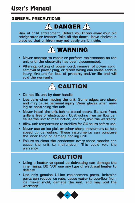
GENERAL PRECAUTIONS
Risk of child entrapment. Before you throw away your oldrefrigerator or freezer: Take off the doors, leave shelves inplace so that children may not easily climb inside.
• Never attempt to repair or perform maintenance on theunit until the electricity has been disconnected.
• Altering, cutting of power cord, removal of power cord,removal of power plug, or direct wiring can cause seriousinjury, fire and/or loss of property and/or life and willvoid the warranty.
• Do not lift unit by door handle.• Use care when moving the unit. Some edges are sharp
and may cause personal injury. Wear gloves when mov-ing or positioning the unit.
• Never install the unit behind closed doors. Be sure frontgrille is free of obstruction. Obstructing free air flow cancause the unit to malfunction, and may void the warranty.
• Allow unit temperature to stabilize for 24 hours before use.• Never use an ice pick or other sharp instrument to help
speed up defrosting. These instruments can puncturethe inner lining or damage cooling unit.
• Failure to clean the condenser every three months cancause the unit to malfunction. This could void the warranty.
CAUTION • Using a heater to speed up defrosting can damage the
inner lining. DO NOT use any type of electrical heater todefrost.
• Use only genuine U-Line replacement parts. Imitationparts can reduce ice rate, cause water to overflow fromice maker mold, damage the unit, and may void the warranty.
!
!
DANGER! !
Users Manual 41923 9/2/03 3:44 PM Page 4

5
INSTALLATIONSITE PREPARATION1. Position the unit on a flat, level surface, capable of supporting the
entire weight of the unit. Remember that the unit will be signifi-cantly heavier once it is fully loaded.
2. Connect the unit to a grounded and polarized 115 VAC, 60Hz,15A circuit (normal household current).
ELECTROCUTION HAZARD!Electrical Grounding Required. This applianceis equipped with a three prong (grounding)polarized plug for your protection againstpossible shock hazards.
• NEVER remove the round grounding prong from the plug.• NEVER use a two-prong grounding adapter.• NEVER use an extension cord to connect power to the
unit.Where a two-prong wall receptacle is encountered or alonger power cord is required, contact a qualified electricianto have it replaced in accordance with applicable electricalcodes.
DANGER! !
Users Manual 41923 9/2/03 3:44 PM Page 5

6
User’s Manual
NOTE Keep in mind that the door ofthe unit may be mounted oneither side of the cabinet (seeREVERSING THE DOOR). AllU-Line units have a zero clear-ance for the door to openwhen the handle is on theright (see Figure 1). Additional clearance is need-ed for Combo Models 29A,29FF, and 75A only, when thedoor handle is on the left. SeeBUILT-IN INSTALLATION foradditional clearance require-ments for these models.
3. On Ice Maker models SP18, BI-95, BI-98 and Combo Series 29and 75, install a 1/4 inch copper water line (not supplied with unit)from the nearest COLD water pipe. When connecting the watersupply, follow these guidelines:• Review the local plumbing codes before you install the unit.• In most instances, the cold water supply will come from the
basement through a hole in the floor.• The water pressure should be between 15 and 150 psi.• Install a SHUT-OFF VALVE in the 1/4 inch supply line.• Connect sufficient tubing to the unit to allow the unit to be
moved for cleaning and servicing. However, make certain thatthe tubing is not pinched or damaged during installation.
• U-Line recommends the use of copper tubing for installation.
4. Position the unit to allow freeair flow through the front grille(see Figure 2).
5. Wipe out inside of unit and icebucket with a damp cloth.
UL005A
UL124
DOORSWING
CABINETOR WALL
0"CLEARANCE
NEEDED
Figure 1
Figure 2
Users Manual 41923 9/2/03 3:44 PM Page 6

7
CONNECTING THE WATER SUPPLY
UL101
POWERCORD
WATER LINE
3. Carefully bend the water sup-ply line into position and con-nect the line to the solenoidvalve (see Figures 5 and 6).Avoid kinking the water sup-ply line.
Figure 3
Figure 5
Figure 6Figure 4
1. Install the 1/4 inch copperwater line from the mainwater source. On ice makermodels BI-95 and BI-98, thewater line is insertedthrough the hole in the rearof the unit to connect to thesolenoid valve in the front(see Figure 3).
UL134
2. Locate the compression fit-ting and ferrule packed in theunit. Slide the compressionfitting and ferrule over the1/4 inch water supply line.Do not use thread sealingcompound or tape. Usingtwo wrenches, tighten thecompression fitting on thesupply line (see Figure 4).
UL103
WATERCONNECTION
UL104WATER LINE
Users Manual 41923 9/2/03 3:44 PM Page 7

8
User’s Manual4. For recessed installations,
allow extra water supply linelength to provide slack for easyremoval from the recessedarea (see Figure 7). This willalso safeguard against kinkingthe line.
NOTE After completing the installation, turn on the water andrecheck water connection for leaks. Apply additional tight-ening if needed. Do not use thread sealing compound ortape.
UL100
NOTEIf you are not intendingto use the ice maker anddo not connect the watersupply (or turn the supplyvalve off), it is imperativeto raise the bin arm ofthe ice maker (see Figure8).
NOTEOn Models BI-95 and BI-98, route the water supply linethrough the unit in such a way as to prevent the line fromcoming in contact with any internal components other thanthe solenoid valve (see Figure 6). Normal operation createssome vibration. A water supply line contacting an internalcomponent or cabinet wall may cause excessive noise dur-ing operation or damage to the line.
5. Install the grille. See GRILLE INSTALLATION.
6. Plug in the power cord.
7. Gently push the unit into position. If desired the unit may be recessedinto cabinet or wall.
UL002A
Figure 8
Figure 7
Users Manual 41923 9/2/03 3:44 PM Page 8

9
8. Allow at least 1-1/2 inches clearance behind the unit for electri-cal and water supply connections.
LEVELING THE UNITIt is important that the unit, primarily the ice maker assembly, is level.All 75 and 15 Series units are equipped with adjustable feet for level-ing and height adjustment (see Figure 9). All other units have rubberfeet.
Figure 9
GRILLE INSTALLATIONNOTE
Model SP18 Icemakers come with the grille alreadyinstalled.
29 AND 75 MODELS
1. With a standard blade screwdriver (or 1/4” nutdriver), removethe screw needed to attach the grille (see Figure 10).
2. Remove the control knob by pulling it toward you.
3. Carefully remove the grille from inside the unit. A small screw holeis located toward the top of the middle recessed section of thegrille.
UL105TURN FOOT TO ADJUST
Users Manual 41923 9/2/03 3:44 PM Page 9

10
User’s Manual
Figure 10
4. Place the two hook-hinges (located on the rear bottom side of thegrille) on the front lip of the unit base. Swing the grille up into posi-tion, aligning the grille and cabinet screw holes (see Figure 11).
Figure 11
5. Insert the screw, being careful not to over tighten.
6. Reinstall control knob.
UL107
UL106
GRILLE SCREW
Users Manual 41923 9/2/03 3:44 PM Page 10

95 AND 98 MODELS
1. With a standard blade screwdriver (or 1/4" nutdriver), removethe screw needed to attach the grille (see Figure 12).
2. Carefully remove the grille from inside the unit. Locate the screw hole at the top, middle recessed section of the grille.
3. Place the two hook-hinges (located on therear bottom side of the grille) on the frontlip of the unit base. Swing the grille up intoposition, aligning the grille and cabinetscrew holes (see Figure 13).
Figure 13
4. Insert the screw, being careful not to over tighten.
UL502
GRILLE SCREW
UL501
11
Figure 12
Users Manual 41923 9/2/03 3:44 PM Page 11

12
User’s Manual
GLASS SHELF INSTALLATION (FOR MODELS WITH GLASS SHELVES)
1. Carefully remove the shelves from inside the unit and remove thepackaging.
2. Slide the shelves onto desired ribs, making sure that the silveredge strip is toward the front of the unit and the decorative graph-ics are on the underside of the shelves. Make sure the shelves areinserted fully into the unit (see Figure 14). The white edge striptowards the rear (Models 15R, 29R and 75R only) prevents cansand bottles from freezing against the cold evaporator.
Figure 14
NOTEBe sure to place shelves with the silver edge to the frontand decorative graphics on the underside.
UL108
Users Manual 41923 9/2/03 3:44 PM Page 12

13
REVERSING THE DOORDepending upon the location of the unit, it may be desirable to changethe side on which the door is mounted.
NOTEOn Combo Models 29A and 29FF (built-in installations only),changing the door mounting to the left side may interferewith ice bucket removal. See BUILT-IN INSTALLATION sec-tion for clearance requirements.
To reverse the door mounting on Models SP18, BI-95, BI-98, 15R,29R, Combo 29A, and Combo 29FF (except Stainless Steel models),perform the following:
1. Remove grille (1 screw). SeeFigure 15.
2. Remove top hinge from cabinet(3 screws). See Figure 16.Hold door to keep it fromfalling.
UL116
REMOVE SCREW
UL109
3. Lift the door off the bottom hinge.
4. Remove bottom hinge from cabinet (2 screws) (see Figure 17).Remove screws on opposite side of cabinet (see Figure 18). Notethat there may be a nut behind one or both screws on either side.
5. Install hinge on opposite side, bottom of cabinet (see Figure 19).Replace nut on back side where installed. Align hinge outer edgewith cabinet before tightening screws.
Figure 15 Figure 16
Users Manual 41923 9/2/03 3:44 PM Page 13

14
User’s Manual
6. Relocate plastic spacer/bushing on bottom of door to oppositeside, and place door on bottom hinge pin (see Figure 20). Cleanout bushing hole in door bottom with a screwdriver if needed.
7. Remove plastic hole plug from door handle and relocate on oppo-site side. See Figure 21.
UL110
UL113
BUSHING
UL112
UL111
Figure 17
Figure 18
Figure 19
Figure 20
Users Manual 41923 9/2/03 3:44 PM Page 14

15
11. Fasten upper hinge to unit (3screws). Partially tightenscrews until door is aligned.See Figure 23.
9. Remove three plastic screwplugs in hinge holes, top ofcabinet, opposite side. Becareful not to scratch cabi-net (see Figure 22).
10. Place door on lower hingepin. Invert and install upperhinge on door.
8. Remove pivot screw from top hinge, invert screw and reinstallpivot screw in top hinge. See Figure 19.
Figure 21
HINGE
RIGHT SIDEDOOR SWING
LEFT SIDEDOOR SWING
RIGHT SIDEHINGE
INVERTSCREW
INVERTHINGE
SCREW
UL115
PLASTICPLUGHOLE
PLASTICPLUGHOLE
UL114A
UL119
Figure 22
Figure 23
Users Manual 41923 9/2/03 3:44 PM Page 15

16
User’s Manual12. Adjust door to assure proper seal. Tighten upper hinge screws
securely.
13. Replace three plastic plugs removed in step 8 into holes on top ofunit. Replace screws in holes in bottom of unit, opposite side.
14. Reinspect door seal and alignment. Adjust if needed.
15. Reinstall grille (1 screw).
NOTEOn Combo Model 75A (built-in installations only), changingthe door mounting to the left side may interfere with icebucket removal. See BUILT-IN INSTALLATION section forclearance requirements.
To reverse the door mounting on Models Combo 75A and 75R(except Stainless Steel models) perform the following:
1. Remove grille (1 screw). See Figure 15.
2. Remove top hinge from cabinet (4 screws). See Figure 16. Holddoor to keep it from falling.
3. Lift the door off the bottom hinge.
4. Remove four plastic plugs in hinge holes, top of cabinet, oppositeside (see Figure 22). Be careful not to scratch cabinet.
5. Remove pivot screw from tophinge, invert screw and rein-stall pivot screw in top hinge.See Figure 21. Do not installhinge on cabinet at this time.
6. Remove bottom hinge fromcabinet (4 screws) andscrews on opposite side ofcabinet (see Figure 24).
7. Remove pivot screw frombottom hinge, invert screwand reinstall pivot screw inhinge (see Figure 21).
UL128
Figure 24
Users Manual 41923 9/2/03 3:44 PM Page 16
17
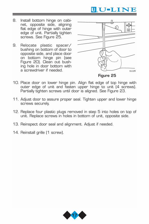
8. Install bottom hinge on cabi-net, opposite side, aligningflat edge of hinge with outeredge of unit. Partially tightenscrews. See Figure 25.
9. Relocate plastic spacer/bushing on bottom of door toopposite side, and place dooron bottom hinge pin (seeFigure 20). Clean out bush-ing hole in door bottom witha screwdriver if needed.
10. Place door on lower hinge pin. Align flat edge of top hinge withouter edge of unit and fasten upper hinge to unit (4 screws).Partially tighten screws until door is aligned. See Figure 23.
11. Adjust door to assure proper seal. Tighten upper and lower hingescrews securely.
12. Replace four plastic plugs removed in step 5 into holes on top ofunit. Replace screws in holes in bottom of unit, opposite side.
13. Reinspect door seal and alignment. Adjust if needed.
14. Reinstall grille (1 screw).
UL129
Figure 25
Users Manual 41923 9/2/03 3:44 PM Page 17

18
User’s Manual
REVERSING A STAINLESS STEEL DOORStainless Steel models are fieldreversible for left or right hand opening. The door opening is easilyreversed by moving the hinge hard-ware to the opposite side (see Figure26) as follows:
1. Remove the bottom hinge (2screws) from door.
2. Remove top hinge (2 screws)from door.
3. Remove door.
4. Remove top hinge (4 screws)from cabinet. Invert and install onbottom, opposite side of cabinet.
5. Remove bottom hinge (4 screws)from cabinet. Invert and install ontop, opposite side of cabinet.
6. Attach top hinge to door.
7. Attach bottom hinge to door.
8. Align as required to assure proper door seal.
ALIGNING THE DOORFor proper door alignment:
1. Loosen top and bottom hinge screws (see Figure 16).
2. Align door squarely with cabinet.
3. Assure gasket is firmly in contact with cabinet all the way aroundthe door (no gaps).
4. Tighten bottom hinge screws.
5. Tighten top hinge screws.
UL318C
Figure 26
Users Manual 41923 9/2/03 3:44 PM Page 18

19
Figure 27
B
A
NOTEWhen inspecting door align-ment, make sure that thelight switch bracket (whereequipped) makes contactwith the light switch plunger(see Figure 27). Also, makesure that the door gasket isnot pinched too tightly onthe hinge side of the door.
CUSTOM DOOR PANEL INSERTINSTALLATION
A custom door panel insert can be installed in most U-Line units. Thedoor will accept a flat or raised panel. The maximum panel thicknesswhere inserted into the door reveal (channel) is 1/4” thick. For raisedpanels, the depth of the reveal is 1/4” on the sides and bottom, and1/2” on the top. The size of the door panel insert is shown below:
The door panel insert must not weigh more than 20 lbs.
Custom Door Panel Dimensions
Model A B
BI-95 13–15/32” 12–15/16”BI-98 15–15/16” 13–15/16”75 Series 28–5/32” 22–15/16”75 SS 29–13/32” 22–15/16”29 Series 21–13/32” 19–13/16”15 Series 28–5/32” 13–15/16”15 SS 29–13/32” 13–15/16”
SS - Stainless steel units
NOTEModel SP18 does not accept customdoor panels.
UL130
Users Manual 41923 9/2/03 3:44 PM Page 19
20
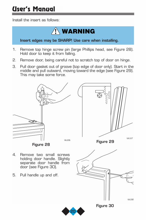
User’s ManualInstall the insert as follows:
Insert edges may be SHARP! Use care when installing.
1. Remove top hinge screw pin (large Phillips head, see Figure 28).Hold door to keep it from falling.
2. Remove door, being careful not to scratch top of door on hinge.
3. Pull door gasket out of groove (top edge of door only). Start in themiddle and pull outward, moving toward the edge (see Figure 29).This may take some force.
!
4. Remove two small screwsholding door handle. Slightlyseparate door handle fromdoor (see Figure 30).
5. Pull handle up and off.
UL131
UL132
Figure 28
UL117
Figure 30
Figure 29
Users Manual 41923 9/2/03 3:44 PM Page 20

21
NOTEUse care not to bend light switch bracket (where installed),located on door bottom when installing door insert. Do notset door on bottom edge when pushing insert into place.
6. Slide custom door panel insert into 1/4 inch channel in door front.
7. Holding door gasket out of the way, replace handle on door mak-ing sure it is seated properly on insert and that screw holes lineup.
8. Install two small screws removed in step 4.
9 Starting at the center and working outward, push door gasket intoplace on door.
10. Place door on bottom hinge pin and install upper hinge screw (seeFigure 28).
11. Reinspect door seal and alignment. Adjust if needed.
BUILT-IN INSTALLATIONYour U-Line product has been designed for either free-standing or built-in installation. When built-in, your U-Line product does not require addi-tional air space for top, sides, or rear. However, the front grille mustNOT be obstructed.
NOTECombo Models 29A, 29FF, and 75A require additionalclearance when the door opens from the right (see Figures32 and 33). This additional clearance allows for the icebucket to be removed from the unit.
Unit Dimensions
Model Width Height DepthSP18 13-15/16" 18-1/2" 25-1/4"95 13-13/16" 24-3/4" 17"98 14-13/16" 27-3/8" 20"
15 Series 14-15/16" 34 - 35" 23-3/4"29 Series 20-13/16" 28-1/2" 24"75 Series 23-7/8" 34 - 35" 24"
Users Manual 41923 9/2/03 3:44 PM Page 21

NOTETo ease unit installationand removal, increase theUnit Dimension measure-ments. It is recommendedthat the cabinet roughopening dimensions beincreased by at least1/4" over the dimensionsgiven for your unit.
22
User’s Manual
HD
W
UL118
CABINET OR WALL UL126
AT LEAST 1" CLEARANCE REQUIRED IFUNIT IS INSTALLED FLUSH WITH
CABINET OR WALL.1.000
CABINETOR WALL UL125
AT LEAST 9" REQUIRED IF UNIT ISINSTALLED ADJACENT TO
CABINET OR WALL.9.000
Figure 32 Figure 33
Figure 31
Users Manual 41923 9/2/03 3:44 PM Page 22

23
INITIAL START-UPOnce installation is complete, the unit is ready for initial start-up andoperation.
NOTEModels BI-95 and BI-98have the ON-OFF switchbehind the front grille. Asmall opening in the topof the grille is providedto access the switch(see Figure 34).
Some models may also turnoff when the temperature con-trol is turned all the waytowards warmer until it stops(clicks).
1. Plug the appliance cord into a 115V polarized and grounded electrical outlet.
2. Check that the ON-OFF switch in the ON position.
3. Open the water supply valve in the main water source. As soon asthe ice maker mold reaches the proper temperature, the icemaker mechanism will fill the mold with water. The first cubes maybe small because of air in the water line. Subsequent cubes will beof standard size. Approximate time for the first cycle is 45 minutes. Allow 2 hours for any Frostfree models.
It is possible that dirt or scale will dislodge in the water line.Always throw away all ice cubes made during the first twoto three hours of operation.
Allow unit temperature to stabilize for 24 hours before use.
UL503
Figure 34
Users Manual 41923 9/2/03 3:44 PM Page 23

24
User’s Manual
NORMAL OPERATIONOn units with refrigerator sections, the unit has been designed toachieve a fresh food temperature of approximately 38°F (temperaturemay vary due to ambient temperature).
On units with ice makers, when the ice bucket is full, the ice makingmechanism will shut off. However, the refrigeration system will contin-ue to cool and maintain the cube supply. On frost free icemaker units,ice production will be lower than on manual defrost units.
Ice production may be interrupted by raisingthe bin arm into an upright and locked posi-tion (the unit will maintain temperature forice storage, see Figure 36).
On Combo units, the refrigerator fresh foodtemperature may vary during the initial man-ufacture of ice. It is recommended that theice bucket be allowed to fill before placingfood in the refrigerator section. The tem-perature control may then be adjusted asneeded (allow 24 hours for temperaturestabilization).
Certain sounds are normal during the unit’s operation. You may hearthe compressor or fan motor, the water valve, sounds of defrost, orice dropping into the ice bucket.
CAUTIONNEVER use an ice pick, knife, or other sharp instrument toseparate cubes. Shake the bucket instead.
The ice bucket MUST be in place to avoid freezing products in therefrigerator section of the Combo Series 29 and 75.
During periods of limited usage or high ambient temperatures, it iscommon for cubes to fuse together. Break apart cubes as necessaryby shaking bucket.
If ice maker is not used regularly, the ice bucket should be emptied peri-odically to ensure fresh cubes.
UL002A
Figure 36
Users Manual 41923 9/2/03 3:44 PM Page 24

25
It is normal for cubes to appear cloudy. This is caused by air beingtrapped in the water due to fast freezing. It has nothing to do with thehealth, taste or chemical make-up of the water. It is the same air thatis in every glass of water you drink.
To provide for higher ice rate (production of more cubes), adjust thetemperature control to a warmer setting. If hollow cubes result, adjusttemperature somewhat colder. For less cube production, adjust to acolder setting.
The ice bucket must be fully inserted in the freezer section.
The ice bin door must be fully closed.
For frost free models: Do not place any objects over air inlet or outletin freezer section.
For frost free models: Light frosting may occur in high humidity condi-tions or if the ice bucket is not pushed in completely.
CHECKING TEMPERATURETo accurately check the tempera-ture, insert an accurate ther-mometer into a plastic (non-break-able) bottle, partially filled withwater. Tighten the bottle capsecurely (see Figure 37).
Place the bottle in the desired areafor 24 hours. Refrain from openingthe unit during the testing period.After 24 hours, check the tempera-ture of the water. Adjust the controlknob if necessary and retest.
Make adjustments in small increments and allow unit tostabilize for 24 hours before making further adjustments.
UL320
Figure 37
Users Manual 41923 9/2/03 3:44 PM Page 25

26
User’s Manual
MARINE USEMany U-Line models are designed to operate in a harsh marine environment. Special considerations include the following:
• For best performance, keep the unit out of direct sunlight.
• On Ice Maker models, turn the unit OFF and dispose of any ice cubesif the unit will not be used for 5 days or more. Prop door open toallow for air circulation and prevent mold and mildew. Do not use anti-freeze in your icemaker.
• If the ambient temperature is expected to drop below 45°F, drain allwater from the unit to prevent freezing damage not covered by thewarranty.
• High ambient temperatures (110°F or higher) may reduce the unit’sability to reach low temperatures and may also reduce the ice pro-duction rate.
ADJUSTING THE TEMPERATURE CONTROL
Models BI-95 and BI-98: Use a flat tip screwdriver to turn adjustingscrew, located behind front grille, clockwise for colder (slower ice pro-duction) or counterclockwise for warmer (faster ice production).
Series 15, 29 and 75: Adjustcontrol setting by turning thenumbered dial (see Figure 38).
Model SP18 temperature control has been preset at thefactory for optimum ice production. Do not attempt tomake adjustments. UL504
12
3
4 5
67
CONTROL
Figure 38
Users Manual 41923 9/2/03 3:44 PM Page 26

27
ADJUSTING ICE CUBE SIZEOn models equipped with an ice maker, the cube size may be adjustedby changing the amount of water injected into the ice maker assembly.
1. Remove the ice maker assembly cover (see Figure 39).
2. Locate the adjusting screw on the ice maker assembly control box.The adjusting screw is just below the minus (–) and plus (+) signson the control box (see Figure 40).
3. Turn the adjusting screw toward the minus (–) sign (clockwise) forsmaller cubes or toward the plus (+) sign (counterclockwise) forlarger cubes.
4. Install the ice maker assembly cover.
Some units are not frost free and must be defrosted periodically. Referto CARE AND CLEANING.
CAUTIONUse only genuine U-Line replacement parts. U-Line icemaker parts are not the same as standard FSP Whirlpoolparts. Using non U-Line parts can reduce ice rate, causewater to overflow from ice maker mold, damage the unit,and may void the warranty.
UL133 UL122
+–
Figure 40Figure 39
Users Manual 41923 9/2/03 3:44 PM Page 27

28
User’s Manual
CARE AND CLEANINGPeriodic cleaning and proper maintenance will ensure efficiency, top performance, and long life. We suggest the following:
• The interior may be cleaned with a mild detergent and warm water.
• Avoid the use of solvent cleaning agents or abrasives on the interior. These cleansers may transmit taste to the ice cubes and food, ordamage or discolor the interior.
• The exterior may be cleaned with a mild detergent and warm water.
• The front grille should be kept free of dust and lint to permit freeair flow to the condenser (seeFigure 41). The condenser coil,located behind the front grille,should be cleaned three to fourtimes each year. Use a brush orvacuum cleaner to remove dirt,lint and other accumulationsfrom the condenser coil.
!
UL005A
Figure 41
The condenser fins are SHARP. DO NOT run hands overcondenser fins.
The solenoid valve inlet screen must be cleaned at least once each yearas follows:
1. Shut off the water at the water supply valve.
2. Remove the entire hose con-nector from the solenoid valve.
3. Use a tooth brush to cleansediment from the inlet screen(see Figure 42). DO NOTremove the screen.
4. Attach the hose connector tothe solenoid valve. Tighten con-nector securely with a pliers.Open the water supply valveand check for leakage at thehose connector.
UL123
Figure 42
Users Manual 41923 9/2/03 3:44 PM Page 28

29
LIGHT BULB REPLACEMENT
Light bulb replacement is simple.
1. Remove the light housing coverby sliding the cover toward thetab, swinging the end oppositethe tab down and pulling downand away (see Figure 43).
2. Replace bulb with genuine U-Linereplacement.
3. Replace the light housing coverby inserting the tab FIRST, slidingthe cover toward the tab andpushing up the other end. Youshould hear a snap/click.
TAB
23
1
UL305
Figure 43
Users Manual 41923 9/2/03 3:44 PM Page 29

30
User’s Manual
DEFROSTINGCAUTION
DO NOT use any type of electrical heating device, ice pick,knife, or other sharp instrument to defrost, as this coulddamage the inner lining or refrigeration system and void thewarranty.
Manual defrost models should be defrosted approximately every 8weeks. However, this interval may not be adequate in periods of highhumidity or heavy usage. Defrost your unit whenever the frost thicknessis 1/4” or greater. To defrost, turn the unit OFF, remove cubes andprop door open at least two inches.
NOTEFrost free units will never need defrosting. Automaticdefrost models do not normally require manual defrosting.However, in extremely high humidity or during periods ofunusually high usage, minimal manual defrosting may berequired.
STORAGEIf the unit is to be stored or not used for extended periods, it will benecessary to drain the system of water.
1. Shut off water supply at the main water source.
2. Disconnect the water supply line from the solenoid valve.
3. Disconnect the water line from the solenoid valve outlet.
4. Allow the unit to run for an hour or more until all remaining icecubes have been ejected from the ice maker assembly.
5. Dry out excess water from the ice maker assembly.
6. Prop the door open at least two inches.
7. Disconnect unit from main electrical power source.
8. Leave water supply line and power cord disconnected until readyto reuse.
NOTEThe use of anti-freeze or other products of this nature is notnecessary and is not recommended.
Users Manual 41923 9/2/03 3:44 PM Page 30

31
TROUBLESHOOTINGBEFORE CALLING FOR SERVICEIf the unit appears to be malfunctioning, read through NORMAL OPER-ATION first. If the problem persists, check the TROUBLESHOOTINGGUIDE. Locate the problem in the guide and refer to the cause and itsremedy before calling for service. The problem could be something verysimple which can be solved without a service call.
TROUBLESHOOTING GUIDE
ELECTROCUTION HAZARDNEVER attempt to repair or perform mainte-nance on the unit until the main electricalpower has been disconnected.
Troubleshooting — What to check when problems occurProblem Possible Cause Remedy
No interior light Loose or burned out Tighten or replace bulb.bulb See LIGHT BULB
REPLACEMENTThe unit is not Light staying on Adjust door so light switchcold enough bracket contacts switch
plunger. See ALIGNINGTHE DOOR
Door gasket not Adjust door. See sealing properly ALIGNING THE DOORDirty condenser coils Clean condenser. See
CARE AND CLEANINGAirflow to front grille Airflow must not be blocked obstructed to front grille.
See INSTALLATIONTemperature not set Turn control knob cold enough CLOCKWISE to set
temperature colder. Allow 24 hours for temperature to stabilize
The unit is not cold The door was left open Turn off the unit to manuallyenough (Frost free causing the evaporator defrost the evaporator.units only) behind the back wall to See DEFROSTING.
fill with frost preventingproper air flow and cooling.
DANGER! !
Users Manual 41923 9/2/03 3:44 PM Page 31
32
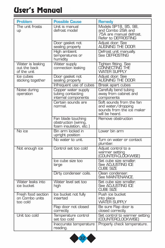
User’s ManualProblem Possible Cause RemedyThe unit frosts Unit is manual Models SP18, 95, 98,up defrost model and Combo 29A and
75A are manual defrost. Refer to DEFROSTING
Door gasket not Adjust door. See sealing properly ALIGNING THE DOORHigh ambient Defrost unit manually. temperatures or See DEFROSTINGhumidity
Water is leaking Water supply Tighten fitting. See out the back connection leaking CONNECTING THE of the unit WATER SUPPLYIce cubes Door gasket not Adjust door. See sticking together sealing properly ALIGNING THE DOOR
Infrequent use of cubes Break apart cubesNoise during Copper water supply Carefully bend tubingoperation tubing contacting away from cabinet and
internal components componentsCertain sounds are Soft sounds from the fannormal. and water/dropping
sounds from the ice makerwill be heard.
Fan blade touching Remove obstructionobstruction (wiring, foam insulation, etc.)
No ice Bin arm locked in Lower bin armupright positionNo water to unit. Turn on water or contact
plumber.Not enough ice Control set too cold Adjust control to a
warmer setting (COUNTER-CLOCKWISE)
Ice cube size too Set cube size smaller. large See ADJUSTING ICE
CUBE SIZEDirty condenser coils. Clean condenser.
See MAINTENANCE.Water leaks into Water level set too Set cube size smaller. ice bucket high See ADJUSTING ICE
CUBE SIZEFresh food section Ice bucket not fully Push ice bucket on Combo units inserted into placetoo cold WATER SUPPLY
Flap door not closed Be sure Flap door iscorrectly closed correctly.
Unit too cold Temperature control Set control to warmer settingset too cold (COUNTERCLOCKWISE)Inaccurate temperature Properly check temperature.reading.
Users Manual 41923 9/2/03 3:44 PM Page 32

33
IF SERVICE IS REQUIREDIf the need for service arises, contact the dealer from whom the unitwas purchased. State the Model Number and Serial Number andexplain the problem. The Model and Serial Number plate is locatedinside unit at upper right hand corner.
If you do not know the name of the selling dealer or local service com-pany, you can check online at www.U-LineService.com.
SPECIFICATIONSIce Production Cube Fresh Food
Unit Type Model Capacity Storage (refrigerator) Freezer DefrostNumber
(per day) Capacity CapacityCapacity Technology
SP18 18 lbs. (8 kg) 12 lbs. (5 kg) Manual
Ice BI-95 23 lbs. (10 kg) 12 lbs. (5 kg) ManualMakers
BI-98 25 lbs. (11 kg) 25 lbs. (11 kg) Manual
75A 22.5 lbs. (10 kg) 13 lbs. (6 kg) 4.2 cu. ft. ManualCombos
(119 L)
29FF 8 lbs. (4 kg) 13 lbs. (6 kg) 2.1 cu. ft. Frost Free(60 L)
29A 22 lbs. (10 kg) 13 lbs. (6 kg) 2.1 cu. ft. Manual(60 L)
75R 6 cu. ft. Automatic(170 L) Defrost
Refrigerators 29R 3.5 cu. ft. Automatic(99 L) Defrost
15R 3.5 cu. ft. Automatic(99 L) Defrost
Users Manual 41923 9/2/03 3:44 PM Page 33

34
User’s Manual
Users Manual 41923 9/2/03 3:44 PM Page 34


R
R R
P.O. Box 245040Milwaukee, WI 53224-9540Phone 414.354.0300FAX 414.354.7905www.U-Line.com
ICE-MAKERS, COMBOS ANDREFRIGERATORS
Printed in U.S.A.P/N 41923 (Rev. 08/03) U
ser’
Use
r’s
Man
ual
s M
anua
l
Cover 41923 9/2/03 3:45 PM Page 1