users guide - infoplc · 6 parts of the packml implementation users guide ... that satisfy the omac...
TRANSCRIPT
Custom Solutions Center
Users Guide
L02 Release
Low Cost OEM PackML Templates
Version LC-1.0

Custom Solutions Center
Users Guide
L02 Release: Part 1 - Overview
Low Cost OEM PackML Templates
Version LC-1.0
Content
1 .........................................................................................................................................................................1 Introduction
2 ...............................................................................................................1 Low Cost PackML Template System Architecture
3 ...................................................................................................................2 Mitsubishi PackML Template Key Components
4 ................................................................................................................2 Mitsubishi PackML Template Program Structure
5 ...............................................................................................................................3 High Level OEM Implementation Steps
6 ..............................................................................................................3 Parts of the PackML Implementation Users Guide
Part 1 – i Custom Solutions Center
Part 1 – ii Custom Solutions Center
Revision History
Version Revision Date Description
L02 Release V1.0 March 31, 2011 Initial release of PackML OEM Implementation Templates for L02 PLC
Mitsubishi PackML Implementation Templates – L02 Release Part 1: Overview
1 Introduction This set of Users Guide documents describes the implementation of Mitsubishi OEM PackML Implementation Templates for L02 PLC1 and steps on how to use the Templates to implement packaging machine control programs by OEM users. Using this Mitsubishi PackML template package enables OEMs to implement a very low cost packaging machine control programs that satisfy the OMAC PackML standard and align with the OMAC PackML Implementation Guide with much reduced effort.
The main functions of this Mitsubishi PackML template package are to (1) handle PackML state and mode transitions, and (2) accumulate machine execution time in each valid mode and state. However, the Mitsubishi PackML templates are NOT intended to be used without modifications or enhancements with machine control PLC, motion and HMI programs. For example, different PLC, motion controller, and GOT types that are used in an actual OEM machine will require PLC, motion controllers, and GOT setup parameters to be adjusted accordingly.
These templates depend on PackML commands and status from PLC, motion and HMI programs to properly perform machine mode and state transitions at the unit machine level per ISA‐88 definition. Thus it is OEM’s responsibility to supply the proper commands and state status from their machine control programs to the Mitsubishi PackML templates in order for the PackML machine modes and states to function properly.
The details on how the machine control programs should be integrated in the Mitsubishi PackML templates are described in this document.
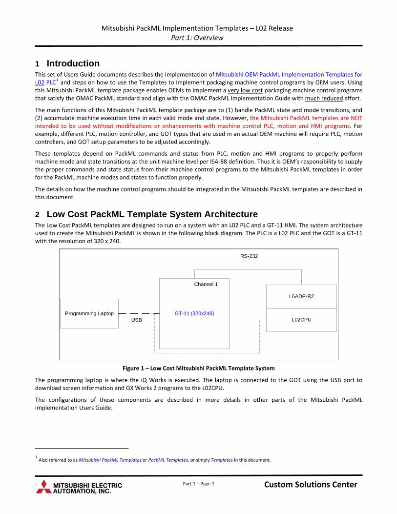
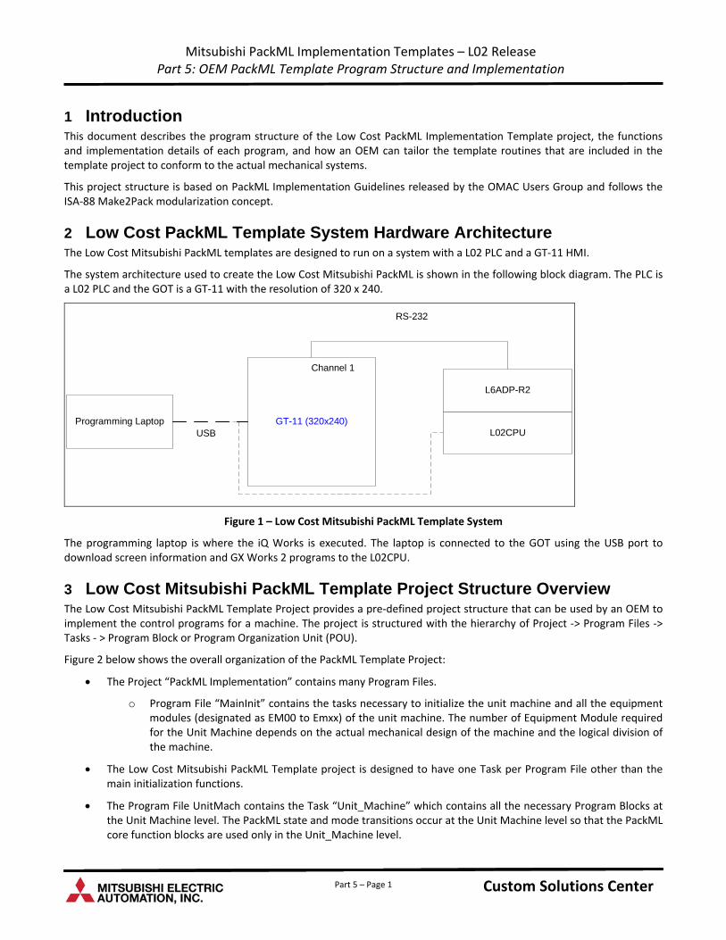
2 Low Cost PackML Template System Architecture The Low Cost PackML templates are designed to run on a system with an L02 PLC and a GT‐11 HMI. The system architecture used to create the Mitsubishi PackML is shown in the following block diagram. The PLC is a L02 PLC and the GOT is a GT‐11 with the resolution of 320 x 240.
Programming Laptop GT-11 (320x240)L02CPUUSB
L6ADP-R2
Channel 1
RS-232
Figure 1 – Low Cost Mitsubishi PackML Template System
The programming laptop is where the iQ Works is executed. The laptop is connected to the GOT using the USB port to download screen information and GX Works 2 programs to the L02CPU.
The configurations of these components are described in more details in other parts of the Mitsubishi PackML Implementation Users Guide.
1 Also referred to as Mitsubishi PackML Templates or PackML Templates, or simply Templates in this document.
Custom Solutions Center Part 1 – Page 1
Mitsubishi PackML Implementation Templates – L02 Release Part 1: Overview
3 Mitsubishi PackML Template Key Components The Mitsubishi PackML Template consists of the following key components that an OEM can use directly without modifications:
1. All PackTags defined and allocated to specific PLC registers
2. PackML_ModeStateManager Function Block
3. PackML_ModeStateTimes Function Block
The PackTags and PackML Core function blocks are developed in GX Works 2 and provided as integral parts of the PackML Template GX Works 2 program in the iQ Works Workspace.
The description and implementation of PackTags are described in Mitsubishi PackML Implementation Users Guide – Part 3 PackTags Design Document. The core PackML function blocks are described in Mitsubishi PackML Implementation Users Guide – Part 4 PackML Core Function Block document.
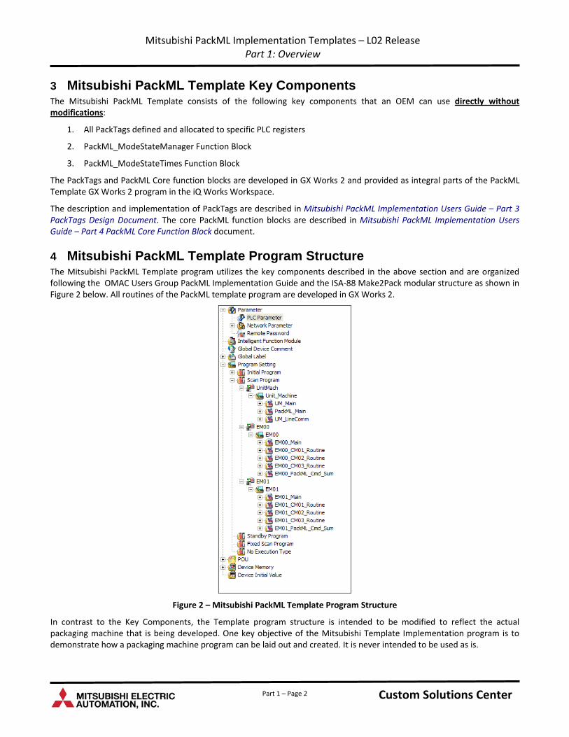
4 Mitsubishi PackML Template Program Structure The Mitsubishi PackML Template program utilizes the key components described in the above section and are organized following the OMAC Users Group PackML Implementation Guide and the ISA‐88 Make2Pack modular structure as shown in Figure 2 below. All routines of the PackML template program are developed in GX Works 2.
Figure 2 – Mitsubishi PackML Template Program Structure
In contrast to the Key Components, the Template program structure is intended to be modified to reflect the actual packaging machine that is being developed. One key objective of the Mitsubishi Template Implementation program is to demonstrate how a packaging machine program can be laid out and created. It is never intended to be used as is.
Custom Solutions Center Part 1 – Page 2
Mitsubishi PackML Implementation Templates – L02 Release Part 1: Overview
Part 1 – Page 3 Custom Solutions Center
As shown Figure 2, the Mitsubishi PackML Template program is designed to represent a packaging machine (Referred to as Unit_Machine) consists of two equipment modules (EM00 and EM01). Each equipment module consists of four Control Modules (CM01 to CM03) for machine operations and a Control Module to integrate appropriate PackML commands and status for each Equipment Module from its control modules CM01 to CM03. An OEM has the flexibility to add or delete equipment modules and control modules to match the actual machine that is being built.
5 High Level OEM Implementation Steps High level steps of tailoring the Mitsubishi PackML Templates to an actual packaging machine are described in this section:
1. Install the latest version of the Mitsubishi iQ Works on the programming computer.
2. Establish the RS232 communication among the L02 PLC and the GOT.
3. Analyze the Unit Machine design and divide the machine into proper equipment modules.
4. Define and allocate control functions into proper modular code and assign them to various control modules.
5. Follow the Mitsubishi PackML Template program structure and add or subtract equipment and control modules as appropriate. For example, one may add additional Equipment Modules EM02 and EM03 (by cutting, pasting, and modifying the labels and names using one of the existing module in the template) or delete control modules EM00_CM03 if it is not needed.
a. The routine names such as “EM00_CM01_Routines” can be modified to “Load_HMI” for example to better reflect the actual purpose of the module which performs “Load Station Operator interface” functions.
6. Develop machine PLC code and assign them in proper modules using iQ Works and GX Works 2.
7. Develop the GOT programs using iQ Works and GT Designer 3.
8. Load programs in PLC and the GOT.
6 Parts of the PackML Implementation Users Guide The Mitsubishi PackML Implementation Users Guide consists of 6 documents:
Documents Descriptions
Part 1 ‐ Overview Overview of the Mitsubishi PackML Template package and program structure
Part 2 – MELSOFT Navigator Descriptions of configuring the PackML Template System using iQ Works MELSOFT Navigator
Part 3 – PackTags Design details of implementing PackTags in the PackML Templates
Part 4 – PackML Function Blocks Design details and PLC code of the core PackML function blocks
Part 5 – Program Structure
Design details on the structure of the OEM Machine program following the OMAC Implementation guide and the Make2Pack modularization. Description on the initialization of PackML states, aggregation of PackML status and commands through various equipment and control modules, and steps to modify the aggregation of PackML status and commands when equipment modules and control modules are added or removed.
Part 6 – GOT Screens Description of GOT sample screens to display PackML current mode and state and also the accumulated time for each mode and state.

Custom Solutions Center
Users Guide
Low Cost OEM PackML Templates L02 Release: Part 2 - MELSOFT Navigator Configuration
Version LC-1.0
Content
1 .........................................................................................................................................................................1 Introduction
2 ......................................................................................................................................1 MELSOFT Navigator Configuration
2.1 ...................................................................................................................................................1 Module Configuration
2.2 ..................................................................................................................................................3 Network Configuration
2.3 .................................................................................................................................3 Adding Programs to PLC and GOT
2.3.1. ..................................................................................................................................4 Creating New PLC Program
2.3.2. ....................................................................................................................................4 Adding Existing Programs
2.3.3. .............................................................................................................................................5 Allocating Programs
3 ................................................................................................................6 Registering Labels in the System Label Database
4 ......................................................................................................................8 Using the System Labels in the GOT Program
4.1 ..........................................................................................................................................8 Establish Route Information
4.2 ..........................................................................................................................9 Setting Up System Labels for GOT Use
4.3 ..................................................................................................................................11 Using the System Labels in GOT
5 ............................................................................................................................................................................16 Summary
Part 2 – i Custom Solutions Center

Part 2 – ii Custom Solutions Center
Revision History
Version Revision Date Description
L02 Release V1.0 March 31, 2011 Initial release of PackML OEM Implementation Templates for L02 PLC
Mitsubishi PackML Implementation Templates – L02 Release Part 2: MELSOFT Navigator Configuration
1 Introduction This document describes the steps of configuring MELSOFT Navigator within the iQ Works software to establish the Low Cost PackML Template System.
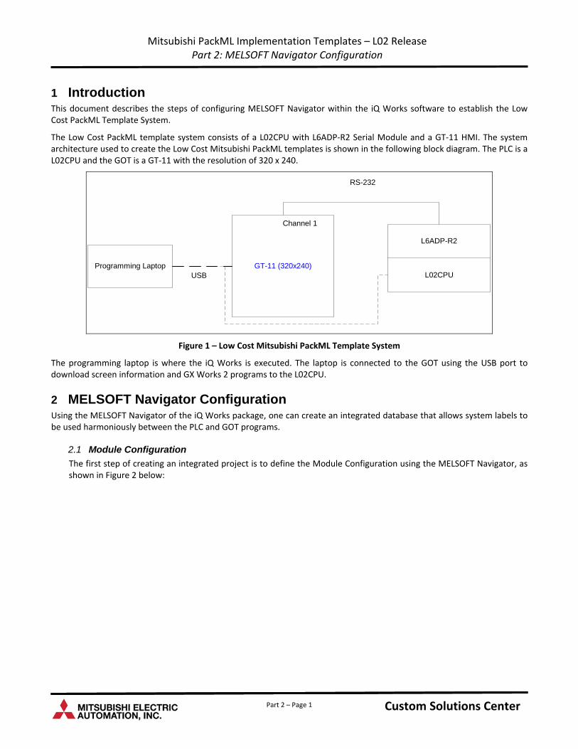
The Low Cost PackML template system consists of a L02CPU with L6ADP‐R2 Serial Module and a GT‐11 HMI. The system architecture used to create the Low Cost Mitsubishi PackML templates is shown in the following block diagram. The PLC is a L02CPU and the GOT is a GT‐11 with the resolution of 320 x 240.
Programming Laptop GT-11 (320x240)L02CPUUSB
L6ADP-R2
Channel 1
RS-232
Figure 1 – Low Cost Mitsubishi PackML Template System
The programming laptop is where the iQ Works is executed. The laptop is connected to the GOT using the USB port to download screen information and GX Works 2 programs to the L02CPU.
2 MELSOFT Navigator Configuration Using the MELSOFT Navigator of the iQ Works package, one can create an integrated database that allows system labels to be used harmoniously between the PLC and GOT programs.
2.1 Module Configuration
The first step of creating an integrated project is to define the Module Configuration using the MELSOFT Navigator, as shown in Figure 2 below:
Custom Solutions Center Custom Solutions Center Part 2 – Page 1
Mitsubishi PackML Implementation Templates – L02 Release Part 2: MELSOFT Navigator Configuration
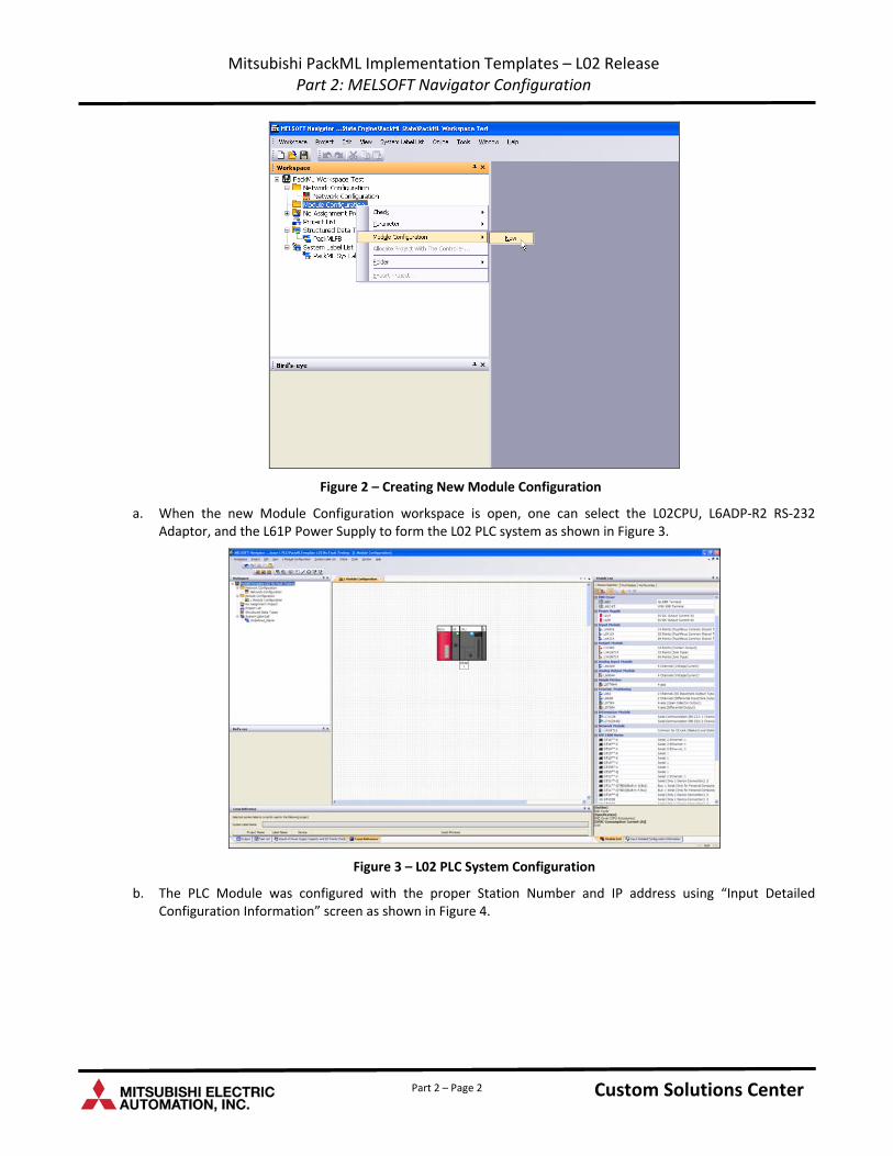
Figure 2 – Creating New Module Configuration
a. When the new Module Configuration workspace is open, one can select the L02CPU, L6ADP‐R2 RS‐232 Adaptor, and the L61P Power Supply to form the L02 PLC system as shown in Figure 3.
Figure 3 – L02 PLC System Configuration
b. The PLC Module was configured with the proper Station Number and IP address using “Input Detailed Configuration Information” screen as shown in Figure 4.
Custom Solutions Center Custom Solutions Center Part 2 – Page 2
Mitsubishi PackML Implementation Templates – L02 Release Part 2: MELSOFT Navigator Configuration
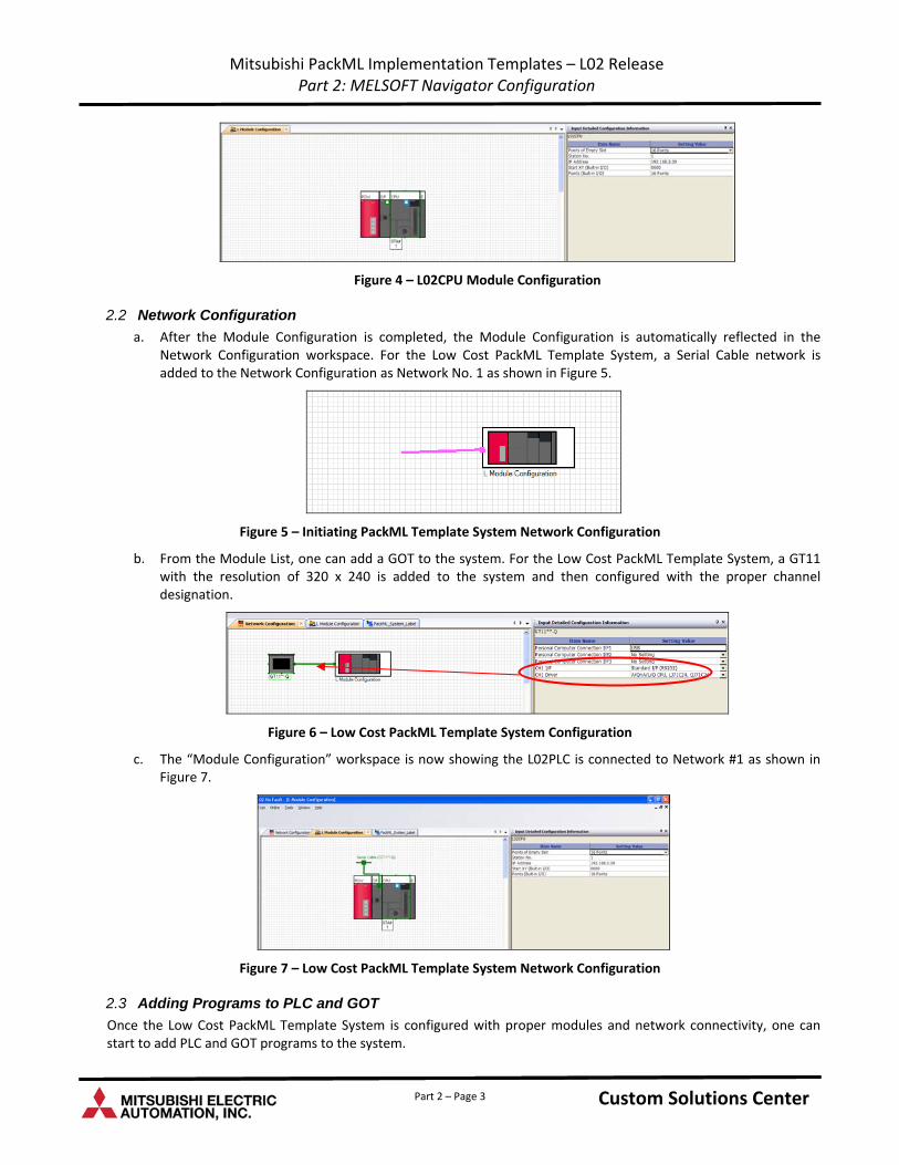
Figure 4 – L02CPU Module Configuration
2.2 Network Configuration
a. After the Module Configuration is completed, the Module Configuration is automatically reflected in the Network Configuration workspace. For the Low Cost PackML Template System, a Serial Cable network is added to the Network Configuration as Network No. 1 as shown in Figure 5.
Figure 5 – Initiating PackML Template System Network Configuration
b. From the Module List, one can add a GOT to the system. For the Low Cost PackML Template System, a GT11 with the resolution of 320 x 240 is added to the system and then configured with the proper channel designation.
Figure 6 – Low Cost PackML Template System Configuration
c. The “Module Configuration” workspace is now showing the L02PLC is connected to Network #1 as shown in Figure 7.
Figure 7 – Low Cost PackML Template System Network Configuration
2.3 Adding Programs to PLC and GOT
Once the Low Cost PackML Template System is configured with proper modules and network connectivity, one can start to add PLC and GOT programs to the system.
Custom Solutions Center Custom Solutions Center Part 2 – Page 3
Mitsubishi PackML Implementation Templates – L02 Release Part 2: MELSOFT Navigator Configuration
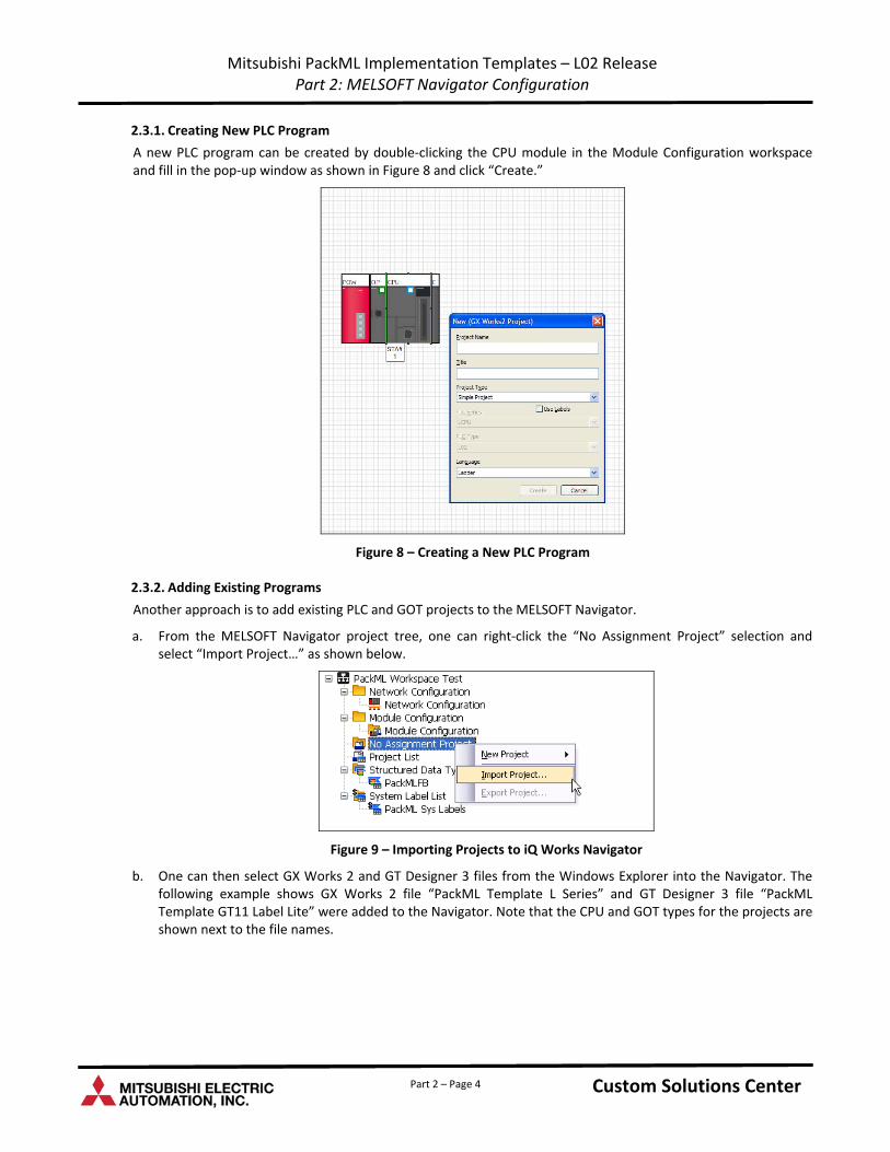
2.3.1. Creating New PLC Program
A new PLC program can be created by double‐clicking the CPU module in the Module Configuration workspace and fill in the pop‐up window as shown in Figure 8 and click “Create.”
Figure 8 – Creating a New PLC Program
2.3.2. Adding Existing Programs
Another approach is to add existing PLC and GOT projects to the MELSOFT Navigator.
a. From the MELSOFT Navigator project tree, one can right‐click the “No Assignment Project” selection and select “Import Project…” as shown below.
Figure 9 – Importing Projects to iQ Works Navigator
b. One can then select GX Works 2 and GT Designer 3 files from the Windows Explorer into the Navigator. The following example shows GX Works 2 file “PackML Template L Series” and GT Designer 3 file “PackML Template GT11 Label Lite” were added to the Navigator. Note that the CPU and GOT types for the projects are shown next to the file names.
Custom Solutions Center Custom Solutions Center Part 2 – Page 4
Mitsubishi PackML Implementation Templates – L02 Release Part 2: MELSOFT Navigator Configuration
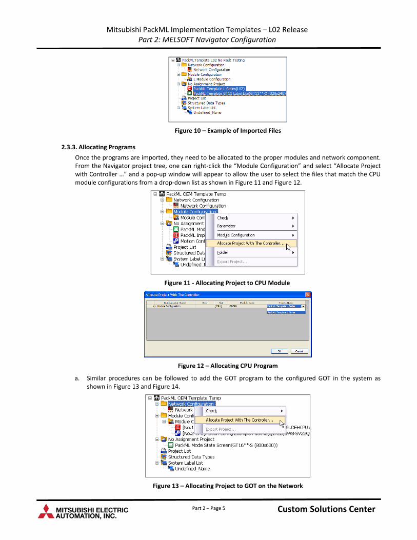
Figure 10 – Example of Imported Files
2.3.3. Allocating Programs
Once the programs are imported, they need to be allocated to the proper modules and network component. From the Navigator project tree, one can right‐click the “Module Configuration” and select “Allocate Project with Controller …” and a pop‐up window will appear to allow the user to select the files that match the CPU module configurations from a drop‐down list as shown in Figure 11 and Figure 12.
Figure 11 ‐ Allocating Project to CPU Module
Figure 12 – Allocating CPU Program
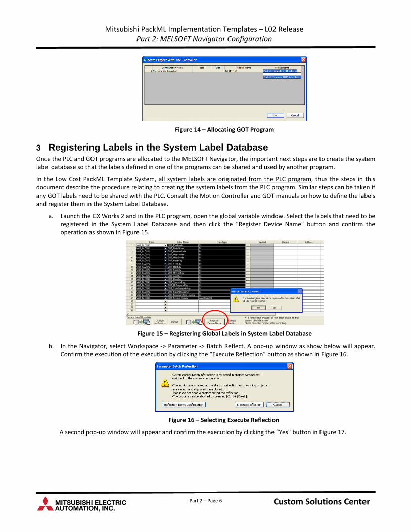
a. Similar procedures can be followed to add the GOT program to the configured GOT in the system as shown in Figure 13 and Figure 14.
Figure 13 – Allocating Project to GOT on the Network
Custom Solutions Center Custom Solutions Center Part 2 – Page 5
Mitsubishi PackML Implementation Templates – L02 Release Part 2: MELSOFT Navigator Configuration
Figure 14 – Allocating GOT Program
3 Registering Labels in the System Label Database Once the PLC and GOT programs are allocated to the MELSOFT Navigator, the important next steps are to create the system label database so that the labels defined in one of the programs can be shared and used by another program.
In the Low Cost PackML Template System, all system labels are originated from the PLC program, thus the steps in this document describe the procedure relating to creating the system labels from the PLC program. Similar steps can be taken if any GOT labels need to be shared with the PLC. Consult the Motion Controller and GOT manuals on how to define the labels and register them in the System Label Database.
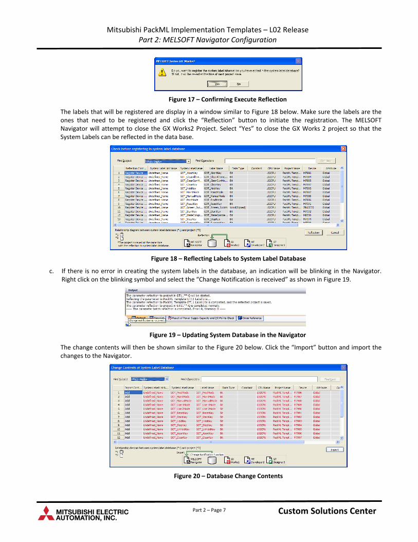
a. Launch the GX Works 2 and in the PLC program, open the global variable window. Select the labels that need to be registered in the System Label Database and then click the “Register Device Name” button and confirm the operation as shown in Figure 15.
Figure 15 – Registering Global Labels in System Label Database
b. In the Navigator, select Workspace ‐> Parameter ‐> Batch Reflect. A pop‐up window as show below will appear. Confirm the execution of the execution by clicking the “Execute Reflection” button as shown in Figure 16.
Figure 16 – Selecting Execute Reflection
A second pop‐up window will appear and confirm the execution by clicking the “Yes” button in Figure 17.
Custom Solutions Center Custom Solutions Center Part 2 – Page 6
Mitsubishi PackML Implementation Templates – L02 Release Part 2: MELSOFT Navigator Configuration
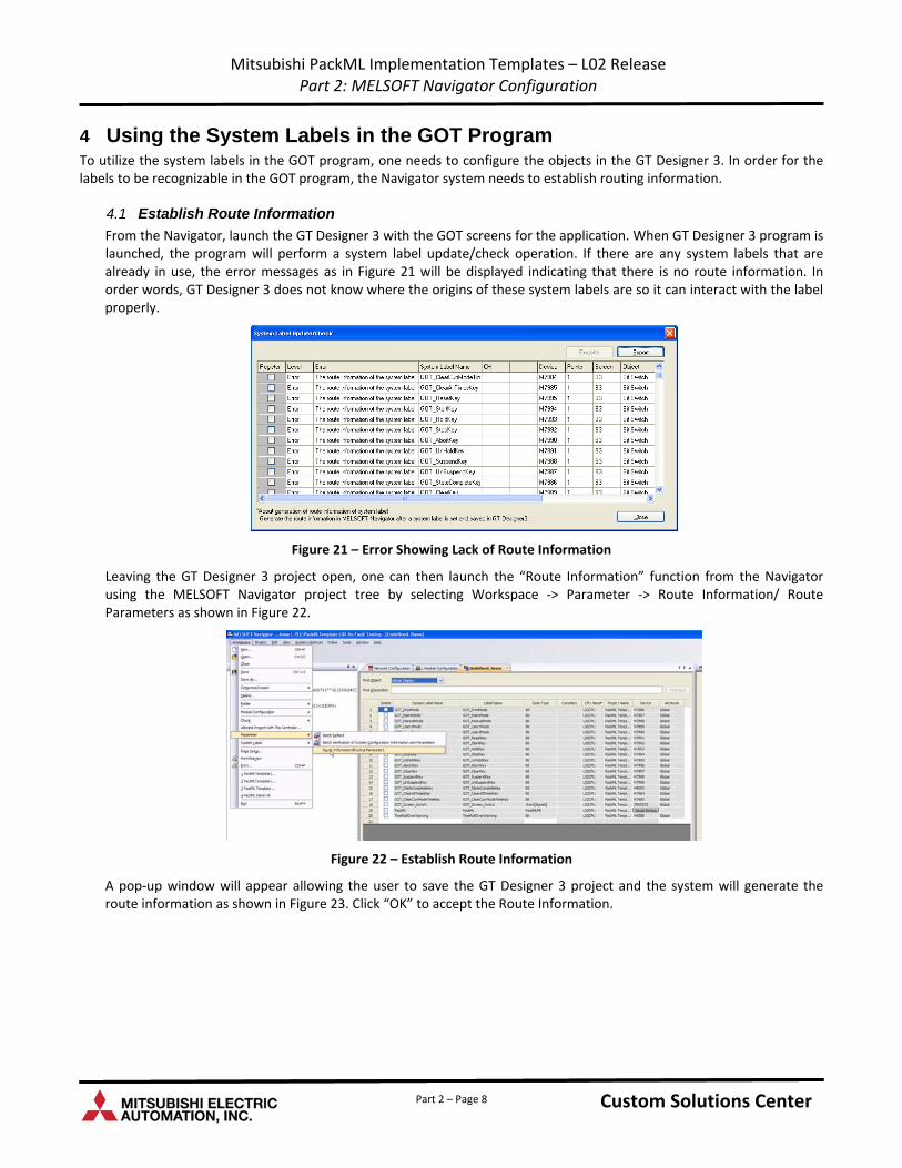
Figure 17 – Confirming Execute Reflection
The labels that will be registered are display in a window similar to Figure 18 below. Make sure the labels are the ones that need to be registered and click the “Reflection” button to initiate the registration. The MELSOFT Navigator will attempt to close the GX Works2 Project. Select “Yes” to close the GX Works 2 project so that the System Labels can be reflected in the data base.
Figure 18 – Reflecting Labels to System Label Database
c. If there is no error in creating the system labels in the database, an indication will be blinking in the Navigator. Right click on the blinking symbol and select the “Change Notification is received” as shown in Figure 19.
Figure 19 – Updating System Database in the Navigator
The change contents will then be shown similar to the Figure 20 below. Click the “Import” button and import the changes to the Navigator.
Figure 20 – Database Change Contents
Custom Solutions Center Custom Solutions Center Part 2 – Page 7
Mitsubishi PackML Implementation Templates – L02 Release Part 2: MELSOFT Navigator Configuration
4 Using the System Labels in the GOT Program To utilize the system labels in the GOT program, one needs to configure the objects in the GT Designer 3. In order for the labels to be recognizable in the GOT program, the Navigator system needs to establish routing information.
4.1 Establish Route Information
From the Navigator, launch the GT Designer 3 with the GOT screens for the application. When GT Designer 3 program is launched, the program will perform a system label update/check operation. If there are any system labels that are already in use, the error messages as in Figure 21 will be displayed indicating that there is no route information. In order words, GT Designer 3 does not know where the origins of these system labels are so it can interact with the label properly.
Figure 21 – Error Showing Lack of Route Information
Leaving the GT Designer 3 project open, one can then launch the “Route Information” function from the Navigator using the MELSOFT Navigator project tree by selecting Workspace ‐> Parameter ‐> Route Information/ Route Parameters as shown in Figure 22.
Figure 22 – Establish Route Information
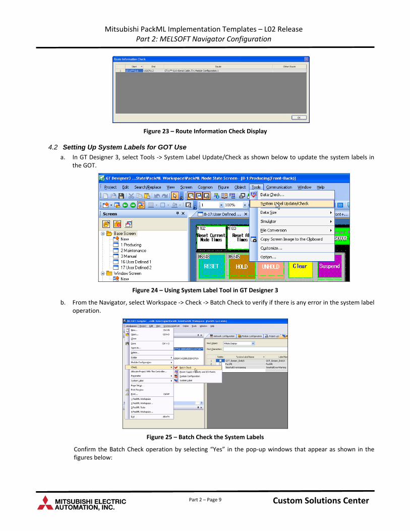
A pop‐up window will appear allowing the user to save the GT Designer 3 project and the system will generate the route information as shown in Figure 23. Click “OK” to accept the Route Information.
Custom Solutions Center Custom Solutions Center Part 2 – Page 8
Mitsubishi PackML Implementation Templates – L02 Release Part 2: MELSOFT Navigator Configuration
Figure 23 – Route Information Check Display
4.2 Setting Up System Labels for GOT Use
a. In GT Designer 3, select Tools ‐> System Label Update/Check as shown below to update the system labels in the GOT.
Figure 24 – Using System Label Tool in GT Designer 3
b. From the Navigator, select Workspace ‐> Check ‐> Batch Check to verify if there is any error in the system label operation.
Figure 25 – Batch Check the System Labels
Confirm the Batch Check operation by selecting “Yes” in the pop‐up windows that appear as shown in the figures below:
Custom Solutions Center Custom Solutions Center Part 2 – Page 9
Mitsubishi PackML Implementation Templates – L02 Release Part 2: MELSOFT Navigator Configuration
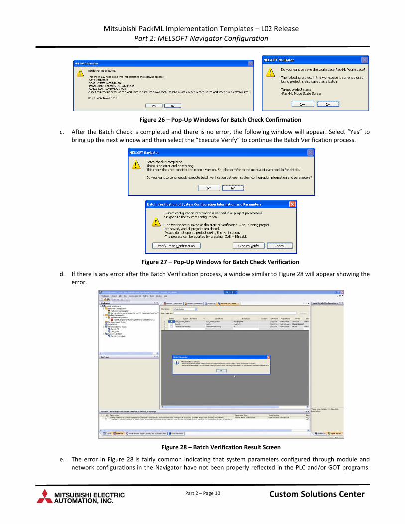
Figure 26 – Pop‐Up Windows for Batch Check Confirmation
c. After the Batch Check is completed and there is no error, the following window will appear. Select “Yes” to bring up the next window and then select the “Execute Verify” to continue the Batch Verification process.
Figure 27 – Pop‐Up Windows for Batch Check Verification
d. If there is any error after the Batch Verification process, a window similar to Figure 28 will appear showing the error.
Figure 28 – Batch Verification Result Screen
e. The error in Figure 28 is fairly common indicating that system parameters configured through module and network configurations in the Navigator have not been properly reflected in the PLC and/or GOT programs.
Custom Solutions Center Custom Solutions Center Part 2 – Page 10
Mitsubishi PackML Implementation Templates – L02 Release Part 2: MELSOFT Navigator Configuration
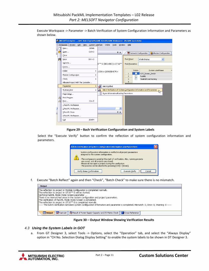
Execute Workspace ‐> Parameter ‐> Batch Verification of System Configuration Information and Parameters as shown below.
Figure 29 – Bach Verification Configuration and System Labels
Select the “Execute Verify” button to confirm the reflection of system configuration information and parameters.
f. Execute “Batch Reflect” again and then “Check”, “Batch Check” to make sure there is no mismatch.
Figure 30 – Output Window Showing Verification Results
4.3 Using the System Labels in GOT
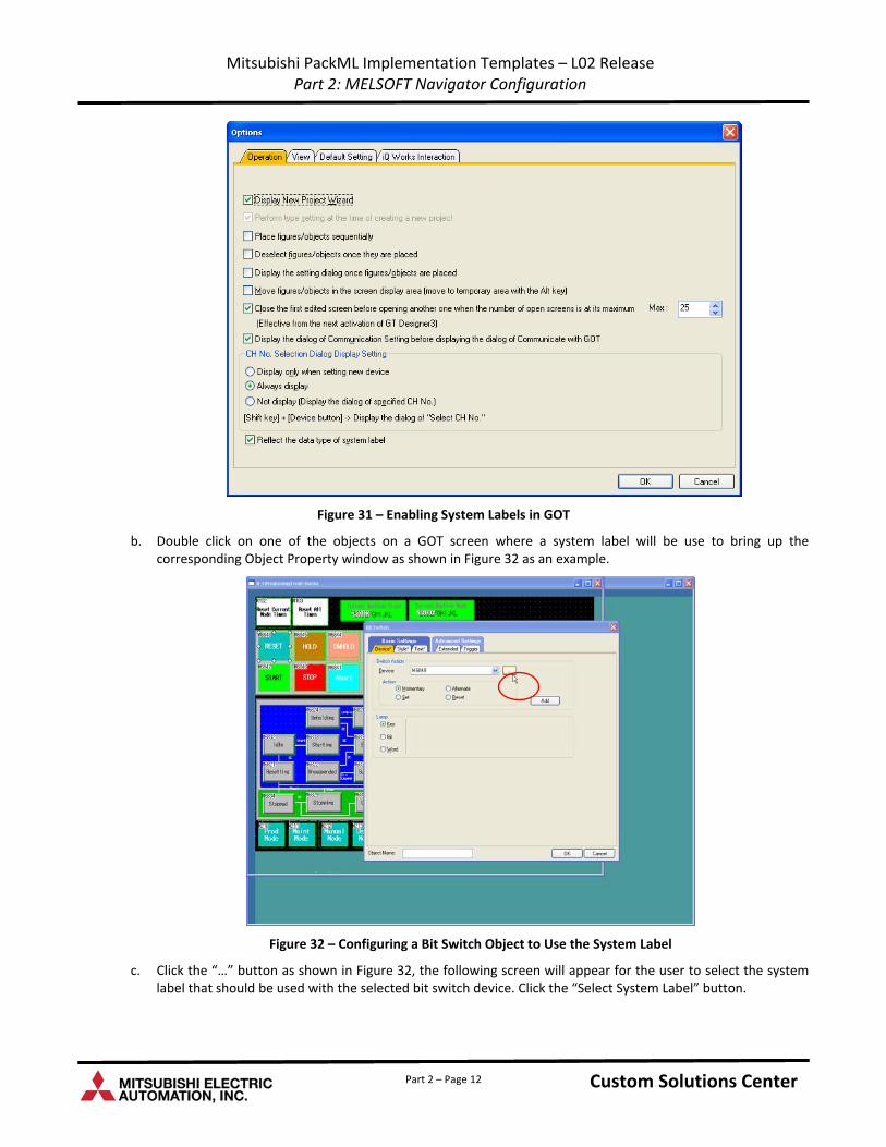
a. From GT Designer 3, select Tools ‐> Options, select the “Operation” tab, and select the “Always Display” option in “CH No. Selection Dialog Display Setting” to enable the system labels to be shown in DT Designer 3.
Custom Solutions Center Custom Solutions Center Part 2 – Page 11
Mitsubishi PackML Implementation Templates – L02 Release Part 2: MELSOFT Navigator Configuration
Figure 31 – Enabling System Labels in GOT
b. Double click on one of the objects on a GOT screen where a system label will be use to bring up the corresponding Object Property window as shown in Figure 32 as an example.
Figure 32 – Configuring a Bit Switch Object to Use the System Label
c. Click the “…” button as shown in Figure 32, the following screen will appear for the user to select the system label that should be used with the selected bit switch device. Click the “Select System Label” button.
Custom Solutions Center Custom Solutions Center Part 2 – Page 12
Mitsubishi PackML Implementation Templates – L02 Release Part 2: MELSOFT Navigator Configuration
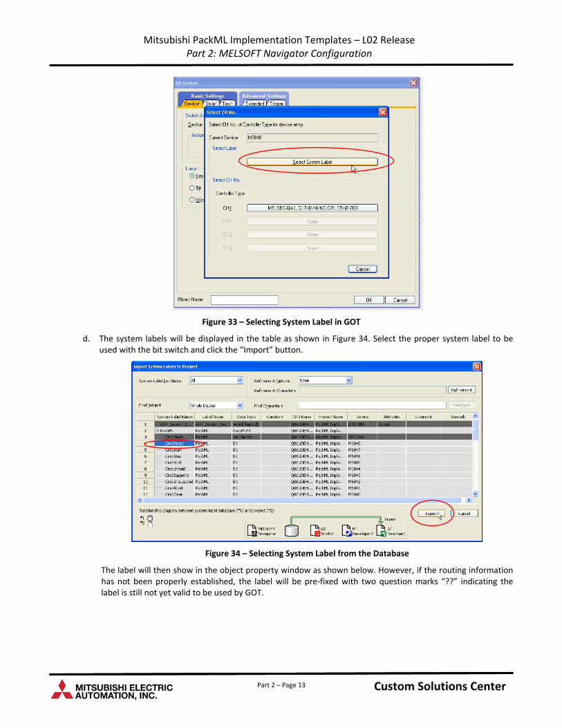
Figure 33 – Selecting System Label in GOT
d. The system labels will be displayed in the table as shown in Figure 34. Select the proper system label to be used with the bit switch and click the “Import” button.
Figure 34 – Selecting System Label from the Database
The label will then show in the object property window as shown below. However, if the routing information has not been properly established, the label will be pre‐fixed with two question marks “??” indicating the label is still not yet valid to be used by GOT.
Custom Solutions Center Custom Solutions Center Part 2 – Page 13
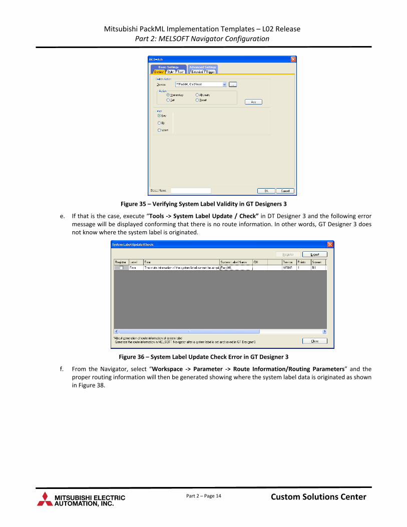
Mitsubishi PackML Implementation Templates – L02 Release Part 2: MELSOFT Navigator Configuration
Figure 35 – Verifying System Label Validity in GT Designers 3
e. If that is the case, execute “Tools ‐> System Label Update / Check” in DT Designer 3 and the following error message will be displayed conforming that there is no route information. In other words, GT Designer 3 does not know where the system label is originated.
Figure 36 – System Label Update Check Error in GT Designer 3
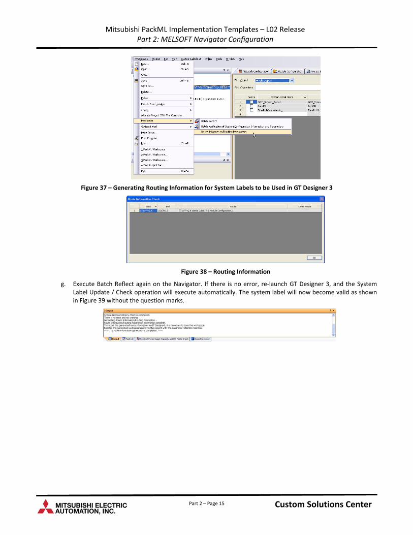
f. From the Navigator, select “Workspace ‐> Parameter ‐> Route Information/Routing Parameters” and the proper routing information will then be generated showing where the system label data is originated as shown in Figure 38.
Custom Solutions Center Custom Solutions Center Part 2 – Page 14
Mitsubishi PackML Implementation Templates – L02 Release Part 2: MELSOFT Navigator Configuration
Figure 37 – Generating Routing Information for System Labels to be Used in GT Designer 3
Figure 38 – Routing Information
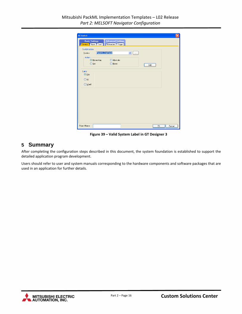
g. Execute Batch Reflect again on the Navigator. If there is no error, re‐launch GT Designer 3, and the System Label Update / Check operation will execute automatically. The system label will now become valid as shown in Figure 39 without the question marks.
Custom Solutions Center Custom Solutions Center Part 2 – Page 15
Mitsubishi PackML Implementation Templates – L02 Release Part 2: MELSOFT Navigator Configuration
Part 2 – Page 16
Figure 39 – Valid System Label in GT Designer 3
5 Summary After completing the configuration steps described in this document, the system foundation is established to support the detailed application program development.
Users should refer to user and system manuals corresponding to the hardware components and software packages that are used in an application for further details.
Custom Solutions Center Custom Solutions Center
Custom Solutions Center
Users Guide
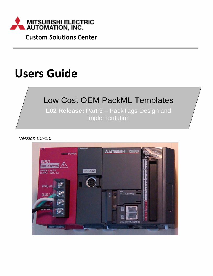
Low Cost OEM PackML Templates L02 Release: Part 3 – PackTags Design and
Implementation
Version LC-1.0
Content
1 .........................................................................................................................................................................1 Introduction
2 ...................................................................................................................................1 Key PackTags Design Considerations
3 ...........................................................................................................................1 PackTags Implementation Considerations
4 ......................................................................................................................................................2 iQ System Configuration
4.1 ..........................................................................................................................................................................3 PLC File
4.2 ............................................................................................................................................................................3 Device
4.3 ........................................................................................................................................4 Built‐in Ethernet Port Setting
5 .......................................................................................................................................6 GX Works2 Label Implementation
5.1 ......................................................................................................................6 Command Labels – PackTags_Command
5.2 ...................................................................................................................................7 Status Labels – PackTags_Status
5.3 ....................................................................................................................................................7 Administrative Labels
6 .............................................................................................................................................9 Kepware Server Configuration
6.1 ............................................................................................................................9 Adding a Channel of Communication
6.2 ............................................................................................................................................................12 Adding Devices
7 ..........................................................................................................................................17 Kepware Tags Implementation
7.1 .........................................................................................................................................................17 Creating the Tags
Part 3 – i Custom Solutions Center Custom Solutions Center

Part 3 – ii Custom Solutions Center Custom Solutions Center
Revision History
Version Revision Date Description
L02 Release V1.0 March 31, 2011 Initial release of PackML OEM Implementation Templates for L02 PLC
Mitsubishi PackML Template Implementations – L02 Release Part 3: PackTags Design and Implementation
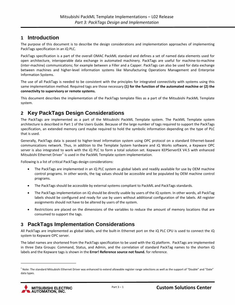
1 Introduction The purpose of this document is to describe the design considerations and implementation approaches of implementing PackTags specification in an iQ PLC.
PackTags specification is a part of the overall OMAC PackML standard and defines a set of named data elements used for open architecture, interoperable data exchange in automated machinery. PackTags are useful for machine‐to‐machine (inter‐machine) communications; for example between a Filler and a Capper. PackTags can also be used for data exchange between machines and higher‐level information systems like Manufacturing Operations Management and Enterprise Information Systems.
The use of all PackTags is needed to be consistent with the principles for integrated connectivity with systems using this same implementation method. Required tags are those necessary (1) for the function of the automated machine or (2) the connectivity to supervisory or remote systems.
This document describes the implementation of the PackTags template files as a part of the Mitsubishi PackML Template system.
2 Key PackTags Design Considerations The PackTags are implemented as a part of the Mitsubishi PackML Template system. The PackML Template system architecture is described in Part 1 of the Users Guide. Because of the large number of tags required to support the PackTags specification, an extended memory card maybe required to hold the symbolic information depending on the type of PLC that is used.
Generally, PackTags data is passed to higher‐level information system using OPC protocol on a standard Ethernet‐based communications network. Thus, in addition to the Template System hardware and iQ Works software, a Kepware OPC server is also integrated to work with the iQ PLC to form a total solution set. Kepware KEPServerEX V4.5 with enhanced Mitsubishi Ethernet Driver1 is used in the PackML Template system implementation.
Following is a list of critical PackTags design considerations:
The PackTags are implemented in an iQ PLC system as global labels and readily available for use by OEM machine control programs. In other words, the tag values should be accessible and be populated by OEM machine control programs.
The PackTags should be accessible by external systems compliant to PackML and PackTags standards.
The PackTags implementation on iQ should be directly usable by users of the iQ system. In other words, all PackTag labels should be configured and ready for use by users without additional configuration of the labels. All register assignments should not have to be altered by users of the system.
Restrictions are placed on the dimensions of the variables to reduce the amount of memory locations that are consumed to support the tags.
3 PackTags Implementation Considerations All PackTags are implemented as global labels, and the built‐in Ethernet port on the iQ PLC CPU is used to connect the iQ system to Kepware OPC server.
The label names are shortened from the PackTags specification to be used with the iQ platform. PackTags are implemented in three Data Groups: Command, Status, and Admin, and the correlation of standard PackTag names to the shorten iQ labels and the Kepware tags is shown in the Error! Reference source not found. for reference.
Custom Solutions Center Custom Solutions Center
1 Note: The standard Mitsubishi Ethernet Driver was enhanced to extend allowable register range selections as well as the support of “Double” and “Date” data types.
Part 3 – 1
Mitsubishi PackML Template Implementations – L02 Release Part 3: PackTags Design and Implementation
Following restrictions are placed on the dimensions of the labels:
There is no remote interface (i.e. the total number of upstream and downstream machines) allowed.
The number of parameters that are given to the unit machine locally is limited to 3.
The number of product types that can be produced on a machine is limited to 2.
The number of process variables needed by a unit machine for processing a specific product is limited to 3.
The number of raw materials (ingredients) that are used by a unit machine in the processing of a particular product is limited to 3.
The number of parameter tags associated to the local interface (e.g. parameters that are displayed or used on a unit locally such as an HMI) is limited to 5.
The number of alarms of a machine is limited to 96.
The number of alarm history is limited to 96.
The number of Modes of a machine is limited to 5
The number of states in each mode of a machine is limited to 17.
The number of material used or consumed in a production machine is limited to 3.
The number of product types that can be processed by a production machine is limited to 3.
The number of product types that can be marked as defective by a production machine is limited to 3.
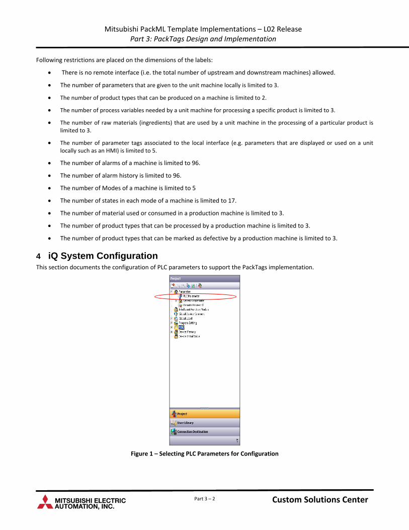
4 iQ System Configuration This section documents the configuration of PLC parameters to support the PackTags implementation.
Figure 1 – Selecting PLC Parameters for Configuration
Custom Solutions Center Custom Solutions Center Part 3 – 2
Mitsubishi PackML Template Implementations – L02 Release Part 3: PackTags Design and Implementation
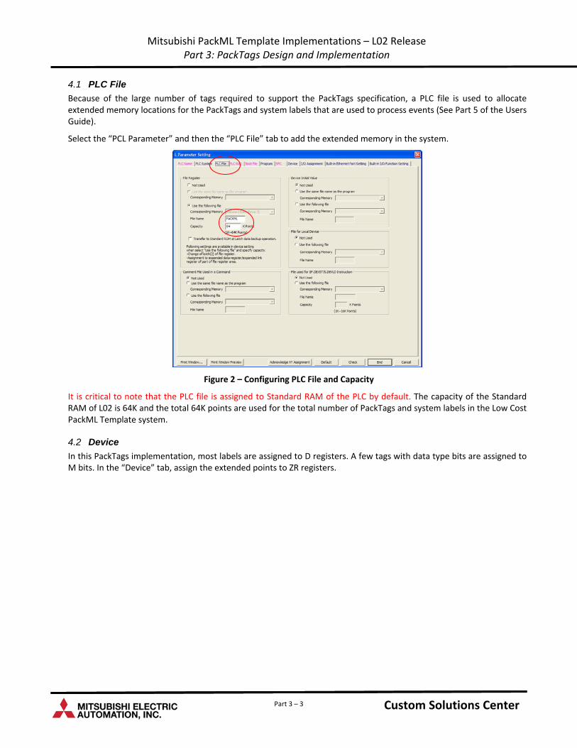
4.1 PLC File
Because of the large number of tags required to support the PackTags specification, a PLC file is used to allocate extended memory locations for the PackTags and system labels that are used to process events (See Part 5 of the Users Guide).
Select the “PCL Parameter” and then the “PLC File” tab to add the extended memory in the system.
Figure 2 – Configuring PLC File and Capacity
It is critical to note that the PLC file is assigned to Standard RAM of the PLC by default. The capacity of the Standard RAM of L02 is 64K and the total 64K points are used for the total number of PackTags and system labels in the Low Cost PackML Template system.
4.2 Device
In this PackTags implementation, most labels are assigned to D registers. A few tags with data type bits are assigned to M bits. In the “Device” tab, assign the extended points to ZR registers.
Custom Solutions Center Custom Solutions Center Part 3 – 3
Mitsubishi PackML Template Implementations – L02 Release Part 3: PackTags Design and Implementation
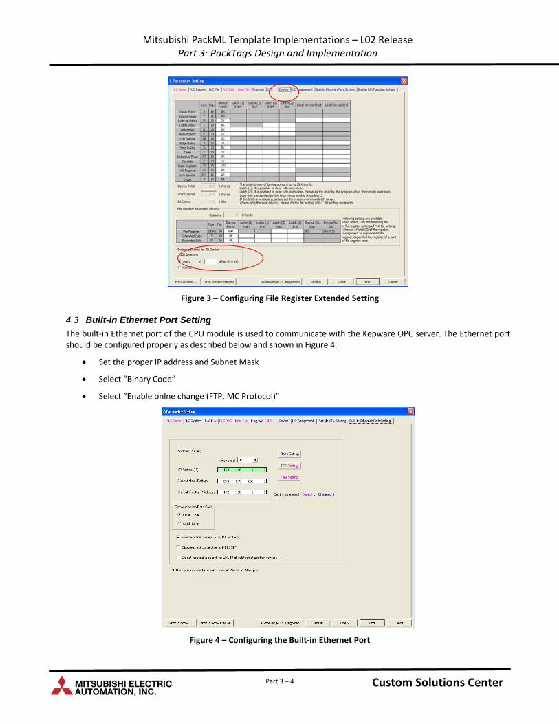
Figure 3 – Configuring File Register Extended Setting
4.3 Built-in Ethernet Port Setting
The built‐in Ethernet port of the CPU module is used to communicate with the Kepware OPC server. The Ethernet port should be configured properly as described below and shown in Figure 4:
Set the proper IP address and Subnet Mask
Select “Binary Code”
Select “Enable onlne change (FTP, MC Protocol)”
Figure 4 – Configuring the Built‐in Ethernet Port
Custom Solutions Center Custom Solutions Center Part 3 – 4
Mitsubishi PackML Template Implementations – L02 Release Part 3: PackTags Design and Implementation
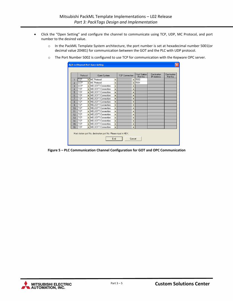
Click the “Open Setting” and configure the channel to communicate using TCP, UDP, MC Protocol, and port number to the desired value.
o In the PackML Template System architecture, the port number is set at hexadecimal number 5001(or decimal value 20481) for communication between the GOT and the PLC with UDP protocol.
o The Port Number 5002 is configured to use TCP for communication with the Kepware OPC server.
Figure 5 – PLC Communication Channel Configuration for GOT and OPC Communication
Custom Solutions Center Custom Solutions Center Part 3 – 5
Mitsubishi PackML Template Implementations – L02 Release Part 3: PackTags Design and Implementation
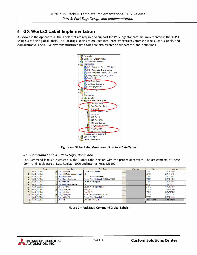
5 GX Works2 Label Implementation As shown in the Appendix, all the labels that are required to support the PackTags standard are implemented in the iQ PLC using GX Works2 global labels. The PackTags labels are grouped into three categories: Command labels, Status labels, and Administrative labels. Five different structured data types are also created to support the label definitions.
Figure 6 – Global Label Groups and Structure Data Types
5.1 Command Labels – PackTags_Command
The Command labels are created in the Global Label section with the proper data types. The assignments of these Command labels start at Data Register 1000 and Internal Relay M8100.
Figure 7 – PackTags_Command Global Labels
Custom Solutions Center Custom Solutions Center Part 3 – 6
Mitsubishi PackML Template Implementations – L02 Release Part 3: PackTags Design and Implementation
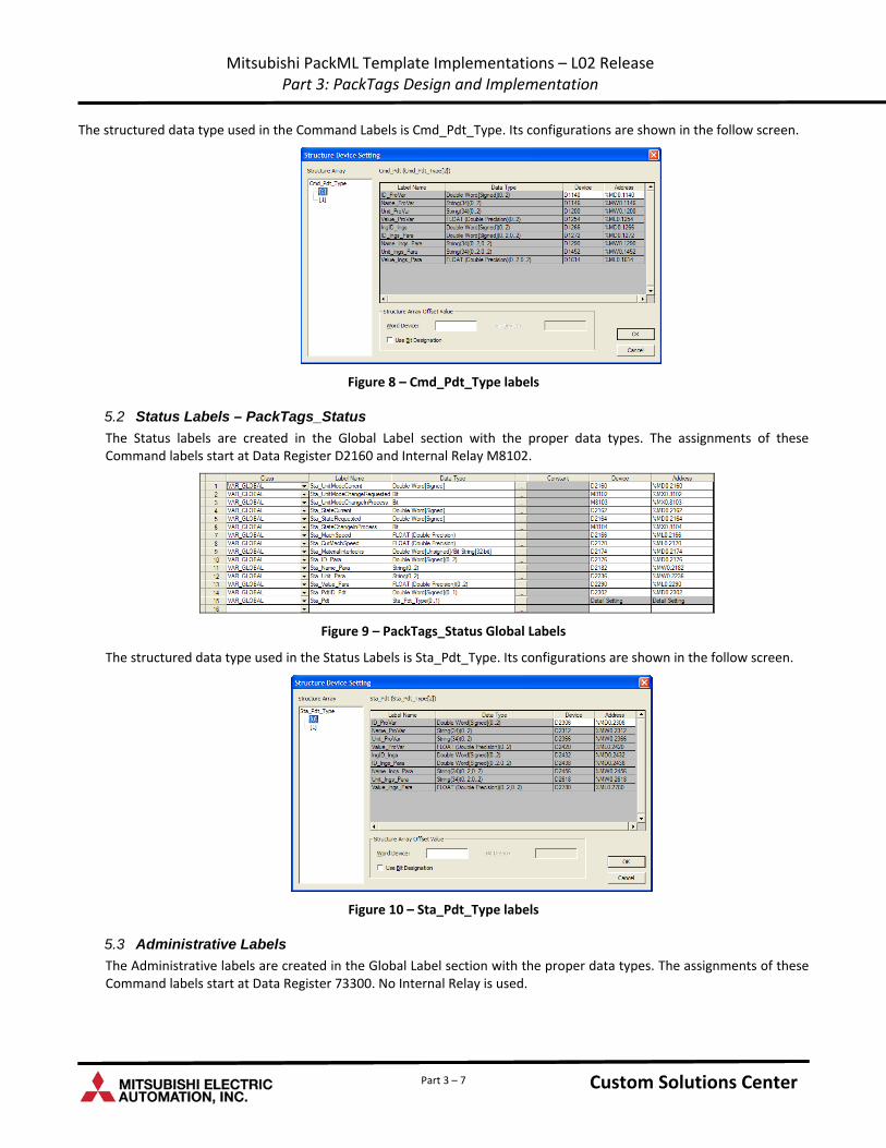
The structured data type used in the Command Labels is Cmd_Pdt_Type. Its configurations are shown in the follow screen.
Figure 8 – Cmd_Pdt_Type labels
5.2 Status Labels – PackTags_Status
The Status labels are created in the Global Label section with the proper data types. The assignments of these Command labels start at Data Register D2160 and Internal Relay M8102.
Figure 9 – PackTags_Status Global Labels
The structured data type used in the Status Labels is Sta_Pdt_Type. Its configurations are shown in the follow screen.
Figure 10 – Sta_Pdt_Type labels
5.3 Administrative Labels
The Administrative labels are created in the Global Label section with the proper data types. The assignments of these Command labels start at Data Register 73300. No Internal Relay is used.
Custom Solutions Center Custom Solutions Center Part 3 – 7
Mitsubishi PackML Template Implementations – L02 Release Part 3: PackTags Design and Implementation
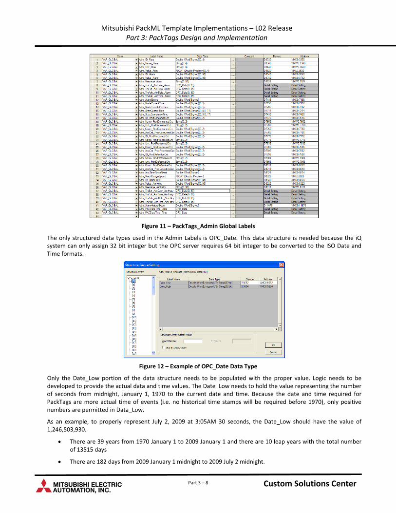
Figure 11 – PackTags_Admin Global Labels
The only structured data types used in the Admin Labels is OPC_Date. This data structure is needed because the iQ system can only assign 32 bit integer but the OPC server requires 64 bit integer to be converted to the ISO Date and Time formats.
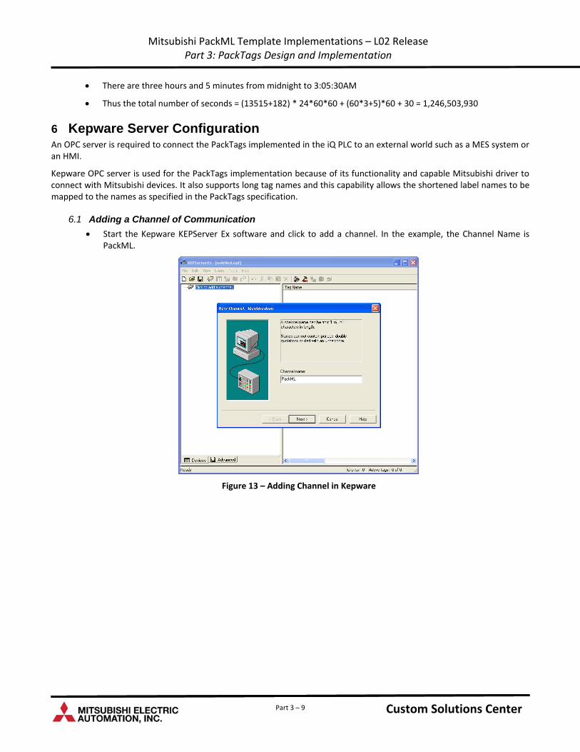
Figure 12 – Example of OPC_Date Data Type
Only the Date_Low portion of the data structure needs to be populated with the proper value. Logic needs to be developed to provide the actual data and time values. The Date_Low needs to hold the value representing the number of seconds from midnight, January 1, 1970 to the current date and time. Because the date and time required for PackTags are more actual time of events (i.e. no historical time stamps will be required before 1970), only positive numbers are permitted in Data_Low.
As an example, to properly represent July 2, 2009 at 3:05AM 30 seconds, the Date_Low should have the value of 1,246,503,930.
There are 39 years from 1970 January 1 to 2009 January 1 and there are 10 leap years with the total number of 13515 days
There are 182 days from 2009 January 1 midnight to 2009 July 2 midnight.
Custom Solutions Center Custom Solutions Center Part 3 – 8
Mitsubishi PackML Template Implementations – L02 Release Part 3: PackTags Design and Implementation
There are three hours and 5 minutes from midnight to 3:05:30AM
Thus the total number of seconds = (13515+182) * 24*60*60 + (60*3+5)*60 + 30 = 1,246,503,930
6 Kepware Server Configuration An OPC server is required to connect the PackTags implemented in the iQ PLC to an external world such as a MES system or an HMI.
Kepware OPC server is used for the PackTags implementation because of its functionality and capable Mitsubishi driver to connect with Mitsubishi devices. It also supports long tag names and this capability allows the shortened label names to be mapped to the names as specified in the PackTags specification.
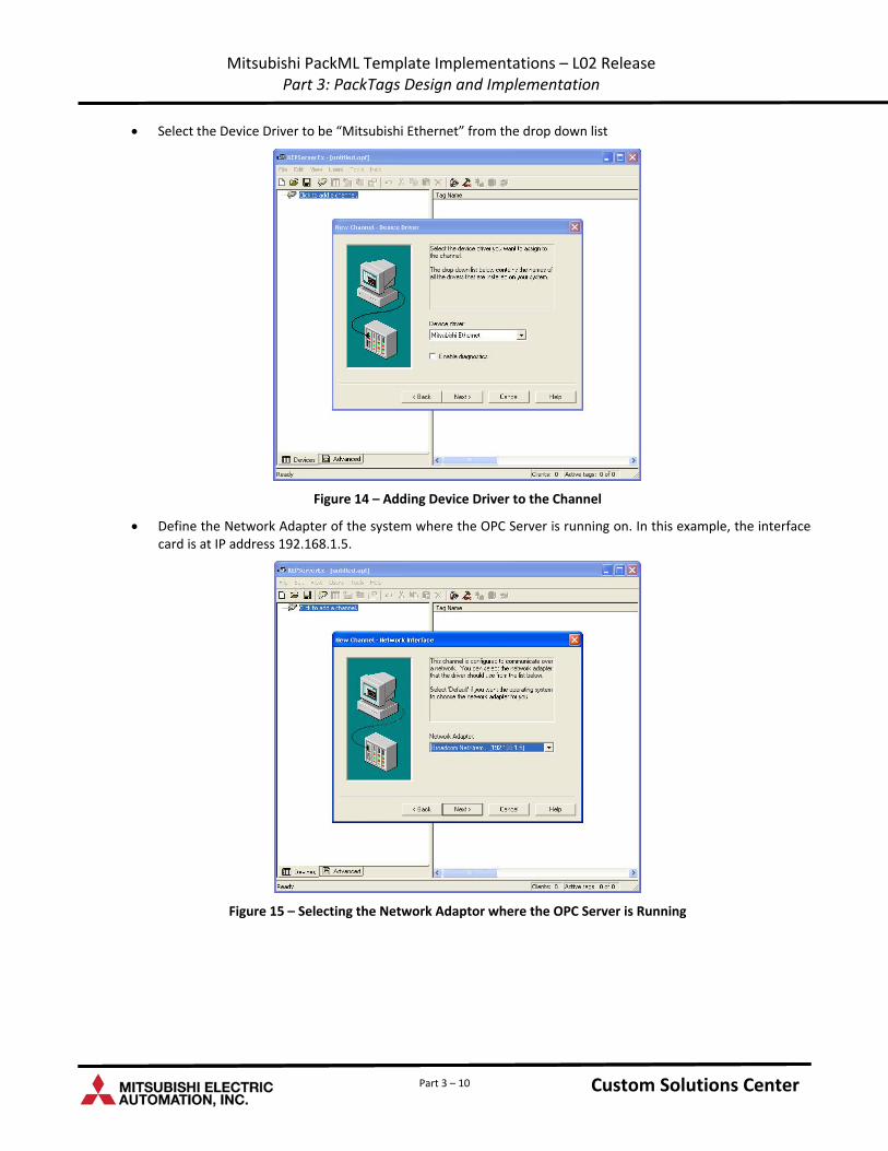
6.1 Adding a Channel of Communication
Start the Kepware KEPServer Ex software and click to add a channel. In the example, the Channel Name is PackML.
Figure 13 – Adding Channel in Kepware
Custom Solutions Center Custom Solutions Center Part 3 – 9
Mitsubishi PackML Template Implementations – L02 Release Part 3: PackTags Design and Implementation
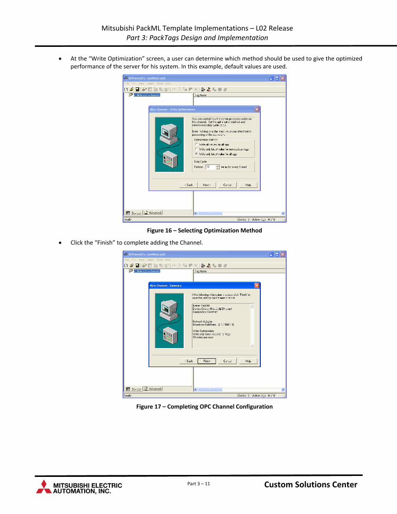
Select the Device Driver to be “Mitsubishi Ethernet” from the drop down list
Figure 14 – Adding Device Driver to the Channel
Define the Network Adapter of the system where the OPC Server is running on. In this example, the interface card is at IP address 192.168.1.5.
Figure 15 – Selecting the Network Adaptor where the OPC Server is Running
Custom Solutions Center Custom Solutions Center Part 3 – 10
Mitsubishi PackML Template Implementations – L02 Release Part 3: PackTags Design and Implementation
At the “Write Optimization” screen, a user can determine which method should be used to give the optimized performance of the server for his system. In this example, default values are used.
Figure 16 – Selecting Optimization Method
Click the “Finish” to complete adding the Channel.
Figure 17 – Completing OPC Channel Configuration
Custom Solutions Center Custom Solutions Center Part 3 – 11
Mitsubishi PackML Template Implementations – L02 Release Part 3: PackTags Design and Implementation
6.2 Adding Devices
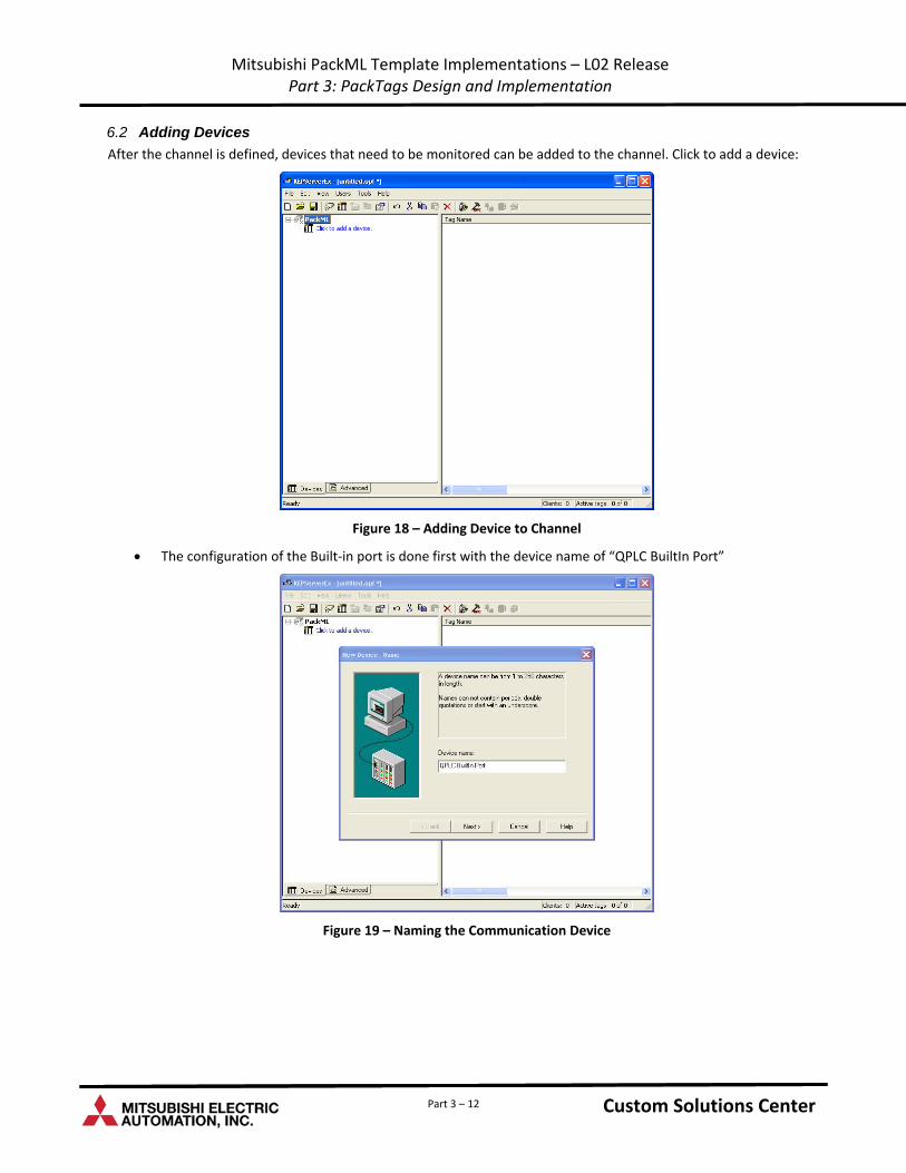
After the channel is defined, devices that need to be monitored can be added to the channel. Click to add a device:
Figure 18 – Adding Device to Channel
The configuration of the Built‐in port is done first with the device name of “QPLC BuiltIn Port”
Figure 19 – Naming the Communication Device
Custom Solutions Center Custom Solutions Center Part 3 – 12
Mitsubishi PackML Template Implementations – L02 Release Part 3: PackTags Design and Implementation
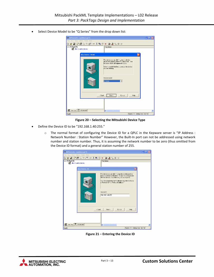
Select Device Model to be “Q Series” from the drop down list:
Figure 20 – Selecting the Mitsubishi Device Type
Define the Device ID to be “192.168.1.40:255.”
o The normal format of configuring the Device ID for a QPLC in the Kepware server is “IP Address : Network Number : Station Number” However, the Built‐In port can not be addressed using network number and station number. Thus, it is assuming the network number to be zero (thus omitted from the Device ID format) and a general station number of 255.
Figure 21 – Entering the Device ID
Custom Solutions Center Custom Solutions Center Part 3 – 13
Mitsubishi PackML Template Implementations – L02 Release Part 3: PackTags Design and Implementation
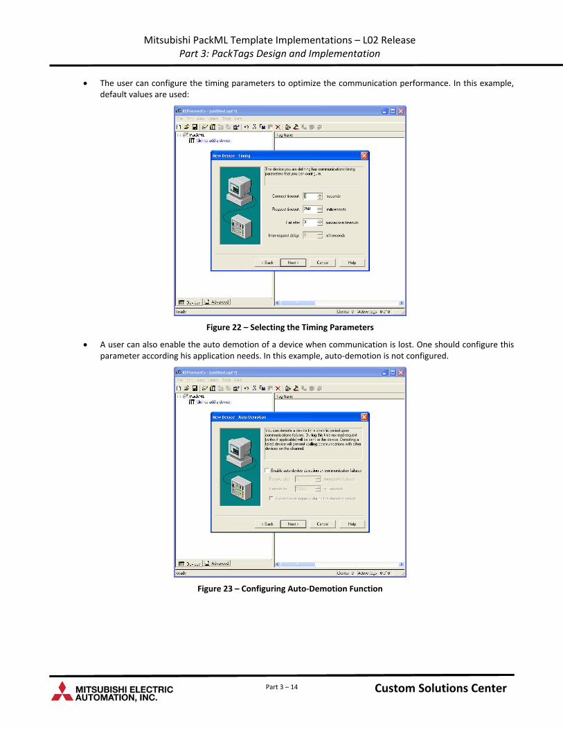
The user can configure the timing parameters to optimize the communication performance. In this example, default values are used:
Figure 22 – Selecting the Timing Parameters
A user can also enable the auto demotion of a device when communication is lost. One should configure this parameter according his application needs. In this example, auto‐demotion is not configured.
Figure 23 – Configuring Auto‐Demotion Function
Custom Solutions Center Custom Solutions Center Part 3 – 14
Mitsubishi PackML Template Implementations – L02 Release Part 3: PackTags Design and Implementation
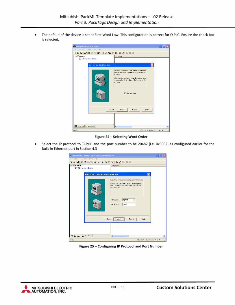
The default of the device is set at First Word Low. This configuration is correct for Q PLC. Ensure the check box is selected.
Figure 24 – Selecting Word Order
Select the IP protocol to TCP/IP and the port number to be 20482 (i.e. 0x5002) as configured earlier for the Built‐in Ethernet port in Section 4.3
Figure 25 – Configuring IP Protocol and Port Number
Custom Solutions Center Custom Solutions Center Part 3 – 15
Mitsubishi PackML Template Implementations – L02 Release Part 3: PackTags Design and Implementation
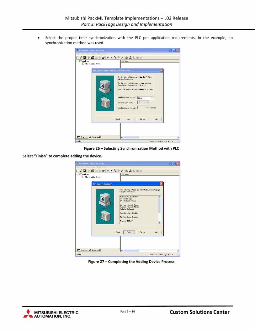
Select the proper time synchronization with the PLC per application requirements. In the example, no synchronization method was used.
Figure 26 – Selecting Synchronization Method with PLC
Select “Finish” to complete adding the device.
Figure 27 – Completing the Adding Device Process
Custom Solutions Center Custom Solutions Center Part 3 – 16
Mitsubishi PackML Template Implementations – L02 Release Part 3: PackTags Design and Implementation
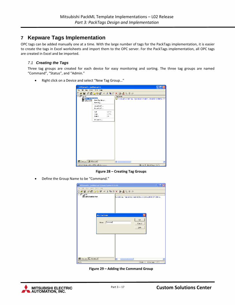
7 Kepware Tags Implementation OPC tags can be added manually one at a time. With the large number of tags for the PackTags implementation, it is easier to create the tags in Excel worksheets and import them to the OPC server. For the PackTags implementation, all OPC tags are created in Excel and be imported.
7.1 Creating the Tags
Three tag groups are created for each device for easy monitoring and sorting. The three tag groups are named “Command”, “Status”, and “Admin.”
Right click on a Device and select “New Tag Group…”
Figure 28 – Creating Tag Groups
Define the Group Name to be “Command.”
Figure 29 – Adding the Command Group
Custom Solutions Center Custom Solutions Center Part 3 – 17
Mitsubishi PackML Template Implementations – L02 Release Part 3: PackTags Design and Implementation
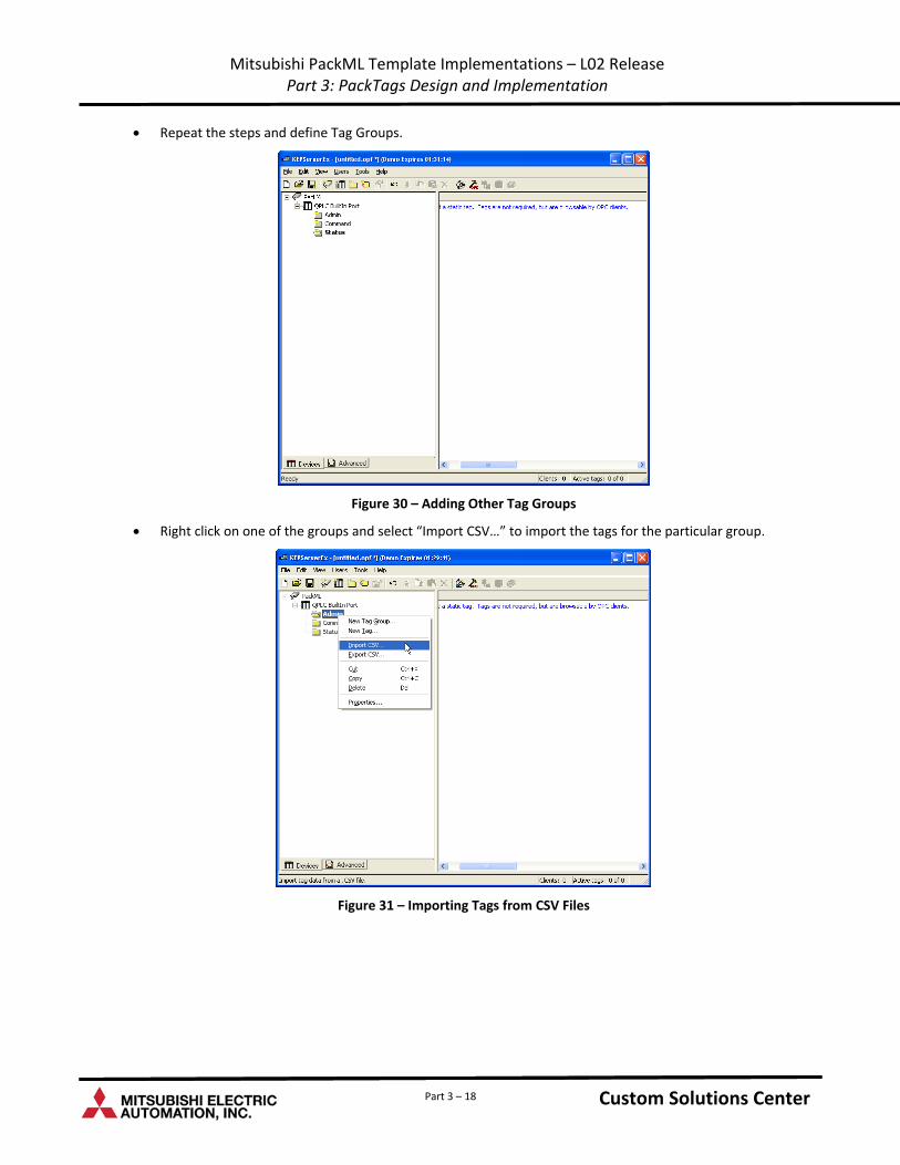
Repeat the steps and define Tag Groups.
Figure 30 – Adding Other Tag Groups
Right click on one of the groups and select “Import CSV…” to import the tags for the particular group.
Figure 31 – Importing Tags from CSV Files
Custom Solutions Center Custom Solutions Center Part 3 – 18
Mitsubishi PackML Template Implementations – L02 Release Part 3: PackTags Design and Implementation
Part 3 – 19
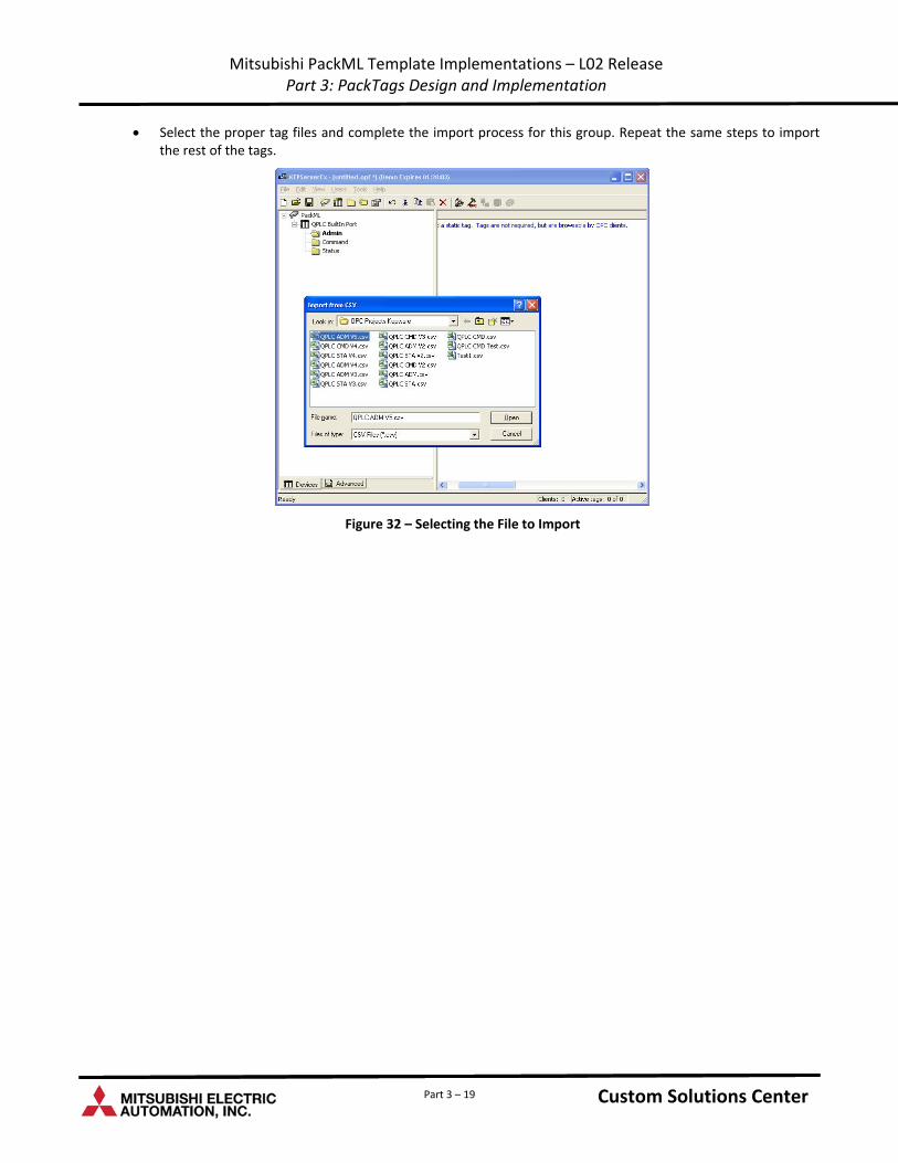
Select the proper tag files and complete the import process for this group. Repeat the same steps to import the rest of the tags.
Figure 32 – Selecting the File to Import
Custom Solutions Center Custom Solutions Center

Custom Solutions Center
Users Guide
L02 Release: Part 4 – PackML Core Function Blocks
Low Cost OEM PackML Templates
Version LC-1.0
Content
1 .........................................................................................................................................................................1 Introduction
2 ...............................................................................................1 Overview of PackML State and Mode Core Function Blocks
3 .....................................................................................................................1 Function Block: PackML_ModeStateManager
3.1 ....................................................................................................................................................................1 Description
3.2 ............................................................................................................................................2 Function Block Operations
3.3 ......................................................................................................................................2 Function Block Local Variables
4 ..........................................................................................................................5 Function Block: PackML_ModeStateTimes
4.1 ....................................................................................................................................................................5 Description
4.2 ...................................................................................................................................5 Timer_32Bit_Sec Function Block
4.3 ............................................................................................................................................6 Function Block Operations
4.4 ......................................................................................................................................6 Function Block Local Variables
5 .......................................................................................................................6 Example Use of the PackML Function Blocks
5.1 ....................................................................................................................................................6 Initialization Example
5.2 ...............................................................................................................................9 Example of Calling Function Blocks
Part 4 – i Custom Solutions Center Custom Solutions Center

Part 4 – ii Custom Solutions Center Custom Solutions Center
Revision History
Version Revision Date Description
L02 Release V1.0 March 31, 2011 Initial release of PackML OEM Implementation Templates for L02 PLC
Mitsubishi PackML Implementation Templates – L02 Release Part 4: PackML Core Function Blocks
1 Introduction The purpose of this document is to describe the design considerations and implementation approaches of implementing PackML specification in an iQ PLC.
PackML specification is a part of the overall OMAC PackML standard and consists of PackTags and PacKML State Engine definitions. PackTags defines a set of named data elements used for open architecture, interoperable data exchange in automated machinery. PackTags are useful for machine‐to‐machine (inter‐machine) communications; for example between a Filler and a Capper. PackTags can also be used for data exchange between machines and higher‐level information systems like Manufacturing Operations Management and Enterprise Information Systems. PackML State Engine defines common procedural programming structures, consistent mode and state definitions that drive a common look and feel between equipment.
The Mitsubishi design of PackTags is documented in Part 3 of this Users Guide. This document describes the implementation of two Mitsubishi PackML core function blocks that handle the PackML Machine State Transitions, Mode Manager, and State and Mode Timers.
The function blocks are implemented using Mitsubishi GX Works2 Structured Ladder Programming language and label programming methods.
2 Overview of PackML State and Mode Core Function Blocks There are two Mitsubishi PackML State and Mode core function blocks:
PackML_ModeStateManager
PackML_ModeStateTimes
The two key functions of the PackML_ModeStateManger are: (1) transitioning the machine from current state to the proper next state based on external commands and state completion status, and (2) handling the transitions of machine modes. The PackML_ModeStateTimes (1) accumulates the current and accumulated time of the machine in each mode and state, and (2) provides the timer values and stores them in appropriate PackTags.
These function blocks, together with their associated global and local labels, are packaged in the overall Mitsubishi PackML OEM Implementation template project.
3 Function Block: PackML_ModeStateManager
3.1 Description
The PackML_ModeStateManager handles the state and mode transitions of a unit machine according to the State and Mode Models defined in the OMAC PackML specification.
To use this Function Block properly in an OEM program, one should ensure the following requirements are satisfied:
1. When an OEM programs a machine to use the PackML Function Blocks, it should initialize the machine to start up with the machine mode set to 3, the Manual Mode condition, and the state to be at the “Stopped” stage during the first scan of the PLC.
2. When an OEM designs the machine, he should determine how many modes the machine will have and how many and what states each mode should have. The selection of modes and states should follow the OMAC PackML Standard when appropriate. Each mode, when defined, should have at least three states: Stopped, Execute, Aborted.
3. Since not all states are configured for all modes, the OEM is responsible for setting up which states are not configured for each mode. He is also responsible for setting up at which states the machine is allowed to change mode. Refer to Part 5 Section 5.1.1 3.3 of the Users Guide for more details.
Custom Solutions Center Custom Solutions Center Part 4 – Page 1
Mitsubishi PackML Implementation Templates – L02 Release Part 4: PackML Core Function Blocks
4. The OEM is also responsible for configuring the names of all modes and states. Refer to Part 5 Section 5.1.1 of the Users Guide for more details.
5. When this FB is used in an OEM program, it is preferable that the FB is always enabled.
6. The label “PackML” is a structured data type and its members should be properly defined before the FB is called.
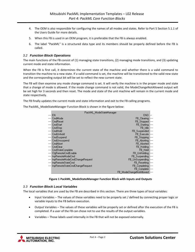
3.2 Function Block Operations
The main functions of the FB consist of (1) managing state transitions, (2) managing mode transitions, and (3) updating current mode and state information.
When the FB is first call, it determines the current state of the machine and whether there is a valid command to transition the machine to a new state. If a valid command is set, the machine will be transitioned to the valid new state and the corresponding output bit will be set to reflect the new current state.
The FB will then examine any mode change command is set. It will verify the machine is in the proper mode and state that a change of mode is allowed. If the mode change command is not valid, the ModeChangeNotAllowed output will be set high for 3 seconds and then reset. The mode and state of the unit machine will remain in the current mode and state respectively.
The FB finally updates the current mode and state information and exit to the FB calling programs.
The PackML_ModeStateManager Function Block is shown in the figure below:
Figure 1 PackML_ModeStateManager Function Block with Inputs and Outputs
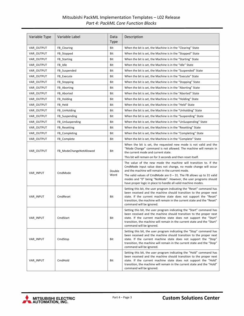
3.3 Function Block Local Variables
The local variables that are used by the FB are described in this section. There are three types of local variables:
Input Variables – The values of these variables need to be properly set / defined by connecting proper logic or variable inputs to the FB before execution.
Output Variables – The values of these variables will be properly set or defined after the execution of the FB is completed. If a user of the FB can chose not to use the results of the output variables.
Variables – Those labels used internally in the FB that will not be exposed externally.
Custom Solutions Center Custom Solutions Center Part 4 – Page 2
Mitsubishi PackML Implementation Templates – L02 Release Part 4: PackML Core Function Blocks
Variable Type Variable Label Data Type
Description
VAR_OUTPUT FB_Clearing Bit When the bit is set, the Machine is in the “Clearing” State
VAR_OUTPUT FB_Stopped Bit When the bit is set, the Machine is in the “Stopped” State
VAR_OUTPUT FB_Starting Bit When the bit is set, the Machine is in the “Starting” State
VAR_OUTPUT FB_Idle Bit When the bit is set, the Machine is in the “Idle” State
VAR_OUTPUT FB_Suspended Bit When the bit is set, the Machine is in the “Suspended” State
VAR_OUTPUT FB_Execute Bit When the bit is set, the Machine is in the “Execute” State
VAR_OUTPUT FB_Stopping Bit When the bit is set, the Machine is in the “Stopping” State
VAR_OUTPUT FB_Aborting Bit When the bit is set, the Machine is in the “Aborting” State
VAR_OUTPUT FB_Aborted Bit When the bit is set, the Machine is in the “Aborted” State
VAR_OUTPUT FB_Holding Bit When the bit is set, the Machine is in the “Holding” State
VAR_OUTPUT FB_Held Bit When the bit is set, the Machine is in the “Held” State
VAR_OUTPUT FB_UnHolding Bit When the bit is set, the Machine is in the “Unholding” State
VAR_OUTPUT FB_Suspending Bit When the bit is set, the Machine is in the “Suspending” State
VAR_OUTPUT FB_UnSuspending Bit When the bit is set, the Machine is in the “UnSuspending” State
VAR_OUTPUT FB_Resetting Bit When the bit is set, the Machine is in the “Resetting” State
VAR_OUTPUT FB_Completing Bit When the bit is set, the Machine is in the “Completing” State
VAR_OUTPUT FB_Complete Bit When the bit is set, the Machine is in the “Complete” State
VAR_OUTPUT FB_ModeChangeNotAllowed Bit
When the bit is set, the requested new mode is not valid and the “Mode Change” command is not allowed. The machine will remain in the current mode and current state.
This bit will remain on for 3 seconds and then reset itself.
VAR_INPUT CmdMode Double Word
The value of the new mode the machine will transition to. If the CmdMode input value does not change, no mode change will occur and the machine will remain in the current mode.
The valid values of CmdMode are 0 – 31. The FB allows up to 31 valid modes and “0” being “NoMode”. However, the user programs should have proper logic in place to handle all valid machine modes.
VAR_INPUT CmdReset Bit
Setting this bit, the user program indicating the “Reset” command has been received and the machine should transition to the proper next state. If the current machine state does not support the “Reset” transition, the machine will remain in the current state and the “Reset” command will be ignored.
VAR_INPUT CmdStart Bit
Setting this bit, the user program indicating the “Start” command has been received and the machine should transition to the proper next state. If the current machine state does not support the “Start” transition, the machine will remain in the current state and the “Start” command will be ignored.
VAR_INPUT CmdStop Bit
Setting this bit, the user program indicating the “Stop” command has been received and the machine should transition to the proper next state. If the current machine state does not support the “Stop” transition, the machine will remain in the current state and the “Stop” command will be ignored.
VAR_INPUT CmdHold Bit
Setting this bit, the user program indicating the “Hold” command has been received and the machine should transition to the proper next state. If the current machine state does not support the “Hold” transition, the machine will remain in the current state and the “Hold” command will be ignored.
Custom Solutions Center Custom Solutions Center Part 4 – Page 3
Mitsubishi PackML Implementation Templates – L02 Release Part 4: PackML Core Function Blocks
Data Variable Type Variable Label Description Type
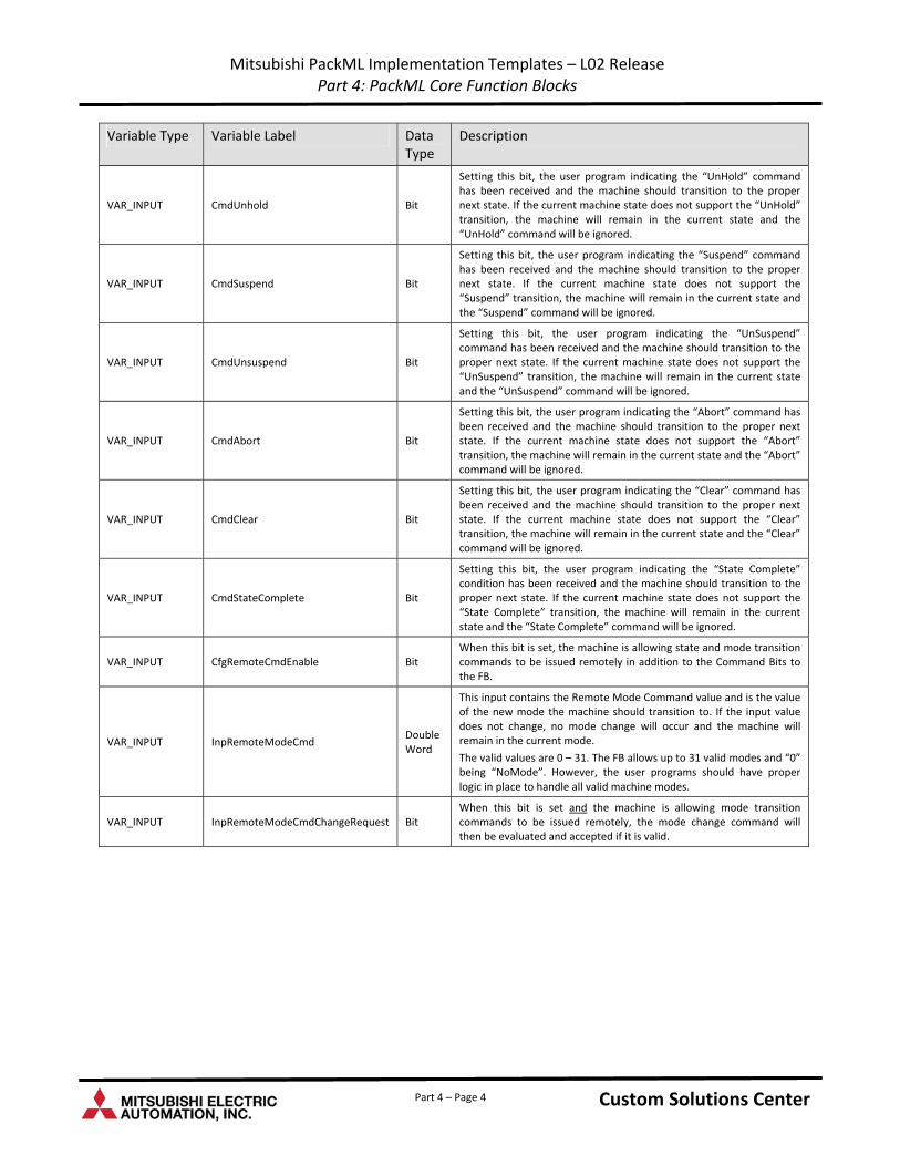
VAR_INPUT CmdUnhold Bit
Setting this bit, the user program indicating the “UnHold” command has been received and the machine should transition to the proper next state. If the current machine state does not support the “UnHold” transition, the machine will remain in the current state and the “UnHold” command will be ignored.
VAR_INPUT CmdSuspend Bit
Setting this bit, the user program indicating the “Suspend” command has been received and the machine should transition to the proper next state. If the current machine state does not support the “Suspend” transition, the machine will remain in the current state and the “Suspend” command will be ignored.
VAR_INPUT CmdUnsuspend Bit
Setting this bit, the user program indicating the “UnSuspend” command has been received and the machine should transition to the proper next state. If the current machine state does not support the “UnSuspend” transition, the machine will remain in the current state and the “UnSuspend” command will be ignored.
VAR_INPUT CmdAbort Bit
Setting this bit, the user program indicating the “Abort” command has been received and the machine should transition to the proper next state. If the current machine state does not support the “Abort” transition, the machine will remain in the current state and the “Abort” command will be ignored.
VAR_INPUT CmdClear Bit
Setting this bit, the user program indicating the “Clear” command has been received and the machine should transition to the proper next state. If the current machine state does not support the “Clear” transition, the machine will remain in the current state and the “Clear” command will be ignored.
VAR_INPUT CmdStateComplete Bit
Setting this bit, the user program indicating the “State Complete” condition has been received and the machine should transition to the proper next state. If the current machine state does not support the “State Complete” transition, the machine will remain in the current state and the “State Complete” command will be ignored.
VAR_INPUT CfgRemoteCmdEnable Bit When this bit is set, the machine is allowing state and mode transition commands to be issued remotely in addition to the Command Bits to the FB.
VAR_INPUT InpRemoteModeCmd Double Word
This input contains the Remote Mode Command value and is the value of the new mode the machine should transition to. If the input value does not change, no mode change will occur and the machine will remain in the current mode.
The valid values are 0 – 31. The FB allows up to 31 valid modes and “0” being “NoMode”. However, the user programs should have proper logic in place to handle all valid machine modes.
VAR_INPUT InpRemoteModeCmdChangeRequest Bit When this bit is set and the machine is allowing mode transition commands to be issued remotely, the mode change command will then be evaluated and accepted if it is valid.
Custom Solutions Center Custom Solutions Center Part 4 – Page 4
Mitsubishi PackML Implementation Templates – L02 Release Part 4: PackML Core Function Blocks
Data Variable Type Variable Label Description Type
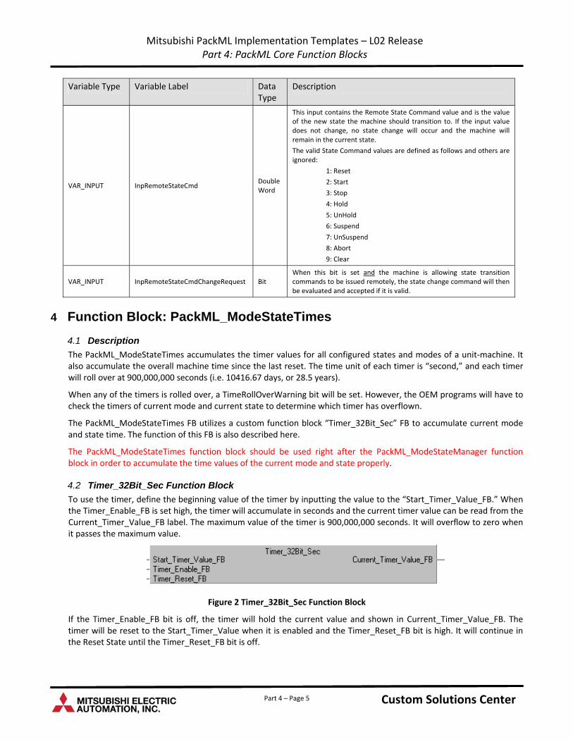
VAR_INPUT InpRemoteStateCmd Double Word
This input contains the Remote State Command value and is the value of the new state the machine should transition to. If the input value does not change, no state change will occur and the machine will remain in the current state.
The valid State Command values are defined as follows and others are ignored:
1: Reset
2: Start
3: Stop
4: Hold
5: UnHold
6: Suspend
7: UnSuspend
8: Abort
9: Clear
VAR_INPUT InpRemoteStateCmdChangeRequest Bit When this bit is set and the machine is allowing state transition commands to be issued remotely, the state change command will then be evaluated and accepted if it is valid.
4 Function Block: PackML_ModeStateTimes
4.1 Description
The PackML_ModeStateTimes accumulates the timer values for all configured states and modes of a unit‐machine. It also accumulate the overall machine time since the last reset. The time unit of each timer is “second,” and each timer will roll over at 900,000,000 seconds (i.e. 10416.67 days, or 28.5 years).
When any of the timers is rolled over, a TimeRollOverWarning bit will be set. However, the OEM programs will have to check the timers of current mode and current state to determine which timer has overflown.
The PackML_ModeStateTimes FB utilizes a custom function block “Timer_32Bit_Sec” FB to accumulate current mode and state time. The function of this FB is also described here.
The PackML_ModeStateTimes function block should be used right after the PackML_ModeStateManager function block in order to accumulate the time values of the current mode and state properly.
4.2 Timer_32Bit_Sec Function Block
To use the timer, define the beginning value of the timer by inputting the value to the “Start_Timer_Value_FB.” When the Timer_Enable_FB is set high, the timer will accumulate in seconds and the current timer value can be read from the Current_Timer_Value_FB label. The maximum value of the timer is 900,000,000 seconds. It will overflow to zero when it passes the maximum value.
Figure 2 Timer_32Bit_Sec Function Block
If the Timer_Enable_FB bit is off, the timer will hold the current value and shown in Current_Timer_Value_FB. The timer will be reset to the Start_Timer_Value when it is enabled and the Timer_Reset_FB bit is high. It will continue in the Reset State until the Timer_Reset_FB bit is off.
Custom Solutions Center Custom Solutions Center Part 4 – Page 5
Mitsubishi PackML Implementation Templates – L02 Release Part 4: PackML Core Function Blocks
Variable Type Variable Label Data Type
Description
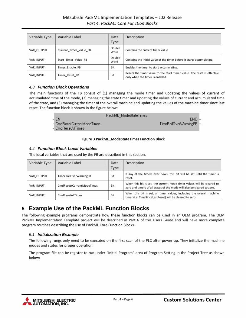
VAR_OUTPUT Current_Timer_Value_FB Double Word
Contains the current timer value.
VAR_INPUT Start_Timer_Value_FB Double Word
Contains the initial value of the timer before it starts accumulating.
VAR_INPUT Timer_Enable_FB Bit Enables the timer to start accumulating.
VAR_INPUT Timer_Reset_FB Bit Resets the timer value to the Start Timer Value. The reset is effective only when the timer is enabled.
4.3 Function Block Operations
The main functions of the FB consist of (1) managing the mode timer and updating the values of current of accumulated time of the mode, (2) managing the state timer and updating the values of current and accumulated time of the state, and (3) managing the timer of the overall machine and updating the values of the machine timer since last reset. The function block is shown in the figure below:
Figure 3 PackML_ModeStateTimes Function Block
4.4 Function Block Local Variables
The local variables that are used by the FB are described in this section.
Variable Type Variable Label Data Type
Description
VAR_OUTPUT TimerRollOverWarningFB Bit If any of the timers over flows, this bit will be set until the timer is reset.
VAR_INPUT CmdResetrCurrentModeTimes Bit When this bit is set, the current mode timer values will be cleared to zero and timers of all states of the mode will also be cleared to zero.
VAR_INPUT CmdResetAllTimes Bit When this bit is set, all timer values, including the overall machine timer (i.e. TimeSinceLastReset) will be cleared to zero.
5 Example Use of the PackML Function Blocks The following example programs demonstrate how these function blocks can be used in an OEM program. The OEM PackML Implementation Template project will be described in Part 6 of this Users Guide and will have more complete program routines describing the use of PackML Core Function Blocks.
5.1 Initialization Example
The following rungs only need to be executed on the first scan of the PLC after power‐up. They initialize the machine modes and states for proper operation.
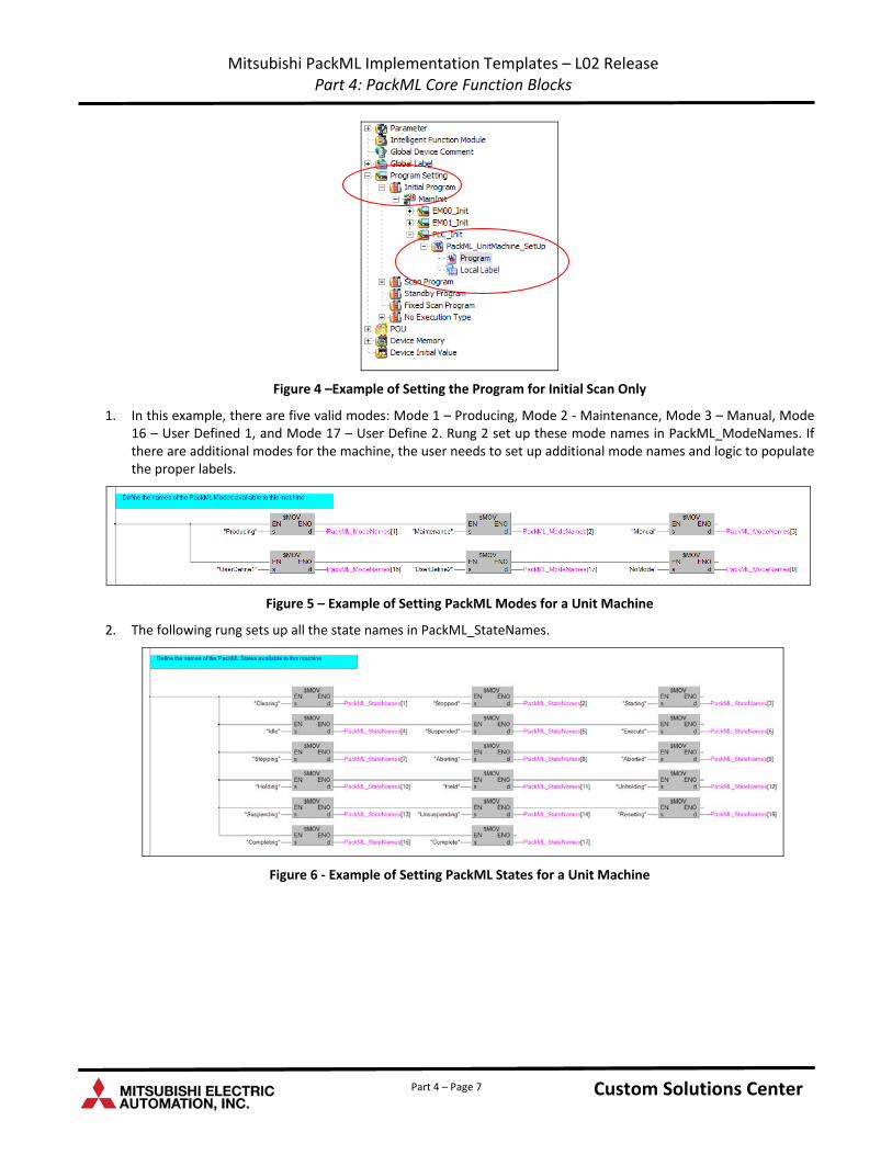
The program file can be register to run under “Initial Program” area of Program Setting in the Project Tree as shown below:
Custom Solutions Center Custom Solutions Center Part 4 – Page 6
Mitsubishi PackML Implementation Templates – L02 Release Part 4: PackML Core Function Blocks
Figure 4 –Example of Setting the Program for Initial Scan Only
1. In this example, there are five valid modes: Mode 1 – Producing, Mode 2 ‐ Maintenance, Mode 3 – Manual, Mode 16 – User Defined 1, and Mode 17 – User Define 2. Rung 2 set up these mode names in PackML_ModeNames. If there are additional modes for the machine, the user needs to set up additional mode names and logic to populate the proper labels.
Figure 5 – Example of Setting PackML Modes for a Unit Machine
2. The following rung sets up all the state names in PackML_StateNames.
Figure 6 ‐ Example of Setting PackML States for a Unit Machine
Custom Solutions Center Custom Solutions Center Part 4 – Page 7
Mitsubishi PackML Implementation Templates – L02 Release Part 4: PackML Core Function Blocks
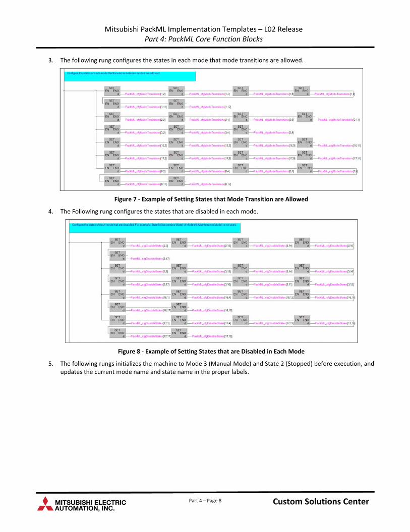
3. The following rung configures the states in each mode that mode transitions are allowed.
Figure 7 ‐ Example of Setting States that Mode Transition are Allowed
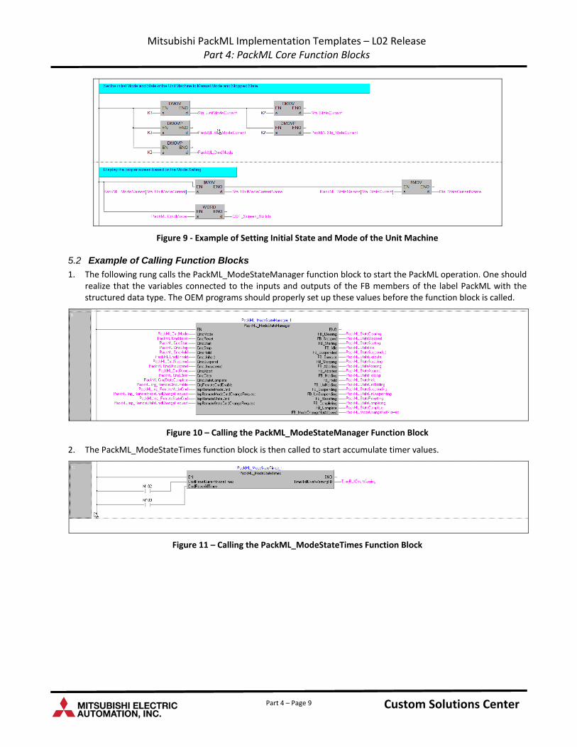
4. The Following rung configures the states that are disabled in each mode.
Figure 8 ‐ Example of Setting States that are Disabled in Each Mode
5. The following rungs initializes the machine to Mode 3 (Manual Mode) and State 2 (Stopped) before execution, and updates the current mode name and state name in the proper labels.
Custom Solutions Center Custom Solutions Center Part 4 – Page 8
Mitsubishi PackML Implementation Templates – L02 Release Part 4: PackML Core Function Blocks
Part 4 – Page 9
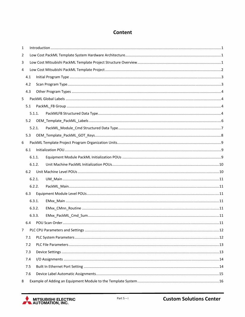
Figure 9 ‐ Example of Setting Initial State and Mode of the Unit Machine
5.2 Example of Calling Function Blocks
1. The following rung calls the PackML_ModeStateManager function block to start the PackML operation. One should realize that the variables connected to the inputs and outputs of the FB members of the label PackML with the structured data type. The OEM programs should properly set up these values before the function block is called.
Figure 10 – Calling the PackML_ModeStateManager Function Block
2. The PackML_ModeStateTimes function block is then called to start accumulate timer values.
Figure 11 – Calling the PackML_ModeStateTimes Function Block
Custom Solutions Center Custom Solutions Center

Custom Solutions Center
Users Guide
Low Cost OEM PackML Templates L02 Release: Part 5 – OEM PackML Template Project
and Implementation
Version LC-1.0
Content
1 .........................................................................................................................................................................1 Introduction
2 ...............................................................................................1 Low Cost PackML Template System Hardware Architecture
3 ...................................................................................1 Low Cost Mitsubishi PackML Template Project Structure Overview
4 ...................................................................................................................2 Low Cost Mitsubishi PackML Template Project
4.1 ......................................................................................................................................................3 Initial Program Type
4.2 ........................................................................................................................................................3 Scan Program Type
4.3 ....................................................................................................................................................4 Other Program Types
5 ..........................................................................................................................................................4 PackML Global Labels
5.1 .........................................................................................................................................................4 PackML_FB Group
5.1.1. ..........................................................................................................................4 PackMLFB Structured Data Type
5.2 ...................................................................................................................................6 OEM_Template_PackML_Labels
5.2.1. ......................................................................................................7 PackML_Module_Cmd Structured Data Type
5.3 .............................................................................................................................8 OEM_Template_PackML_GOT_Keys
6 .......................................................................................................9 PackML Template Project Program Organization Units
6.1 ...........................................................................................................................................................9 Initialization POU
6.1.1. ..................................................................................................9 Equipment Module PackML Initialization POUs
6.1.2. ..........................................................................................................10 Unit Machine PackML Initialization POUs
6.2 ............................................................................................................................................10 Unit Machine Level POUs
6.2.1. ...........................................................................................................................................................11 UM_Main
6.2.2. .....................................................................................................................................................11 PackML_Main
6.3 ...................................................................................................................................11 Equipment Module Level POUs
6.3.1. ........................................................................................................................................................11 EMxx_Main
6.3.2. ........................................................................................................................................11 EMxx_CMnn_Routine
6.3.3. ..................................................................................................................................11 EMxx_PackML_Cmd_Sum
6.4 ...........................................................................................................................................................11 POU Scan Order
7 .....................................................................................................................................12 PLC CPU Parameters and Settings
7.1 ...............................................................................................................................................12 PLC System Parameters
7.2 .....................................................................................................................................................13 PLC File Parameters
7.3 ............................................................................................................................................................13 Device Settings
7.4 ..........................................................................................................................................................14 I/O Assignments
7.5 ......................................................................................................................................14 Built In Ethernet Port Setting
7.6 ..........................................................................................................................15 Device Label Automatic Assignments
8 .................................................................................16 Example of Adding an Equipment Module to the Template System
Part 5 – i Custom Solutions Center Custom Solutions Center Custom Solutions Center
8.1 ................................................................................................................................................16 Adding EM02_Init POU
8.2 ..........................................................................................................................................20 Adding EM02 Program File
8.3 ...............................................................................................................................27 Modifying PackML_Main Routine
9 .........................................................................................28 Example of Adding a Control Module to the Template System
10 .....................................................................................................31 Issuing PackML Commands in a Machine Program
10.1 .......................................................31 Example 1: Transition from Producing Mode Starting State to Execute State
10.2 .........................................................32 Example 2: Transition from Manual Mode Execute State to Stopping State
Part 5 – ii Custom Solutions Center Custom Solutions Center Custom Solutions Center
Part 5 – iii Custom Solutions Center Custom Solutions Center Custom Solutions Center
Revision History
Version Revision Date Description
L02 Release V1.0 March 31, 2011 Initial release of PackML OEM Implementation Templates for L02 PLC
Mitsubishi PackML Implementation Templates – L02 Release Part 5: OEM PackML Template Program Structure and Implementation
1 Introduction This document describes the program structure of the Low Cost PackML Implementation Template project, the functions and implementation details of each program, and how an OEM can tailor the template routines that are included in the template project to conform to the actual mechanical systems.
This project structure is based on PackML Implementation Guidelines released by the OMAC Users Group and follows the ISA‐88 Make2Pack modularization concept.
2 Low Cost PackML Template System Hardware Architecture The Low Cost Mitsubishi PackML templates are designed to run on a system with a L02 PLC and a GT‐11 HMI.
The system architecture used to create the Low Cost Mitsubishi PackML is shown in the following block diagram. The PLC is a L02 PLC and the GOT is a GT‐11 with the resolution of 320 x 240.
Programming Laptop GT-11 (320x240)L02CPUUSB
L6ADP-R2
Channel 1
RS-232
Figure 1 – Low Cost Mitsubishi PackML Template System
The programming laptop is where the iQ Works is executed. The laptop is connected to the GOT using the USB port to download screen information and GX Works 2 programs to the L02CPU.
3 Low Cost Mitsubishi PackML Template Project Structure Overview The Low Cost Mitsubishi PackML Template Project provides a pre‐defined project structure that can be used by an OEM to implement the control programs for a machine. The project is structured with the hierarchy of Project ‐> Program Files ‐> Tasks ‐ > Program Block or Program Organization Unit (POU).
Figure 2 below shows the overall organization of the PackML Template Project:
The Project “PackML Implementation” contains many Program Files.
o Program File “MainInit” contains the tasks necessary to initialize the unit machine and all the equipment modules (designated as EM00 to Emxx) of the unit machine. The number of Equipment Module required for the Unit Machine depends on the actual mechanical design of the machine and the logical division of the machine.
The Low Cost Mitsubishi PackML Template project is designed to have one Task per Program File other than the main initialization functions.
The Program File UnitMach contains the Task “Unit_Machine” which contains all the necessary Program Blocks at the Unit Machine level. The PackML state and mode transitions occur at the Unit Machine level so that the PackML core function blocks are used only in the Unit_Machine level.
Custom Solutions Center Custom Solutions Center Custom Solutions Center Part 5 – Page 1
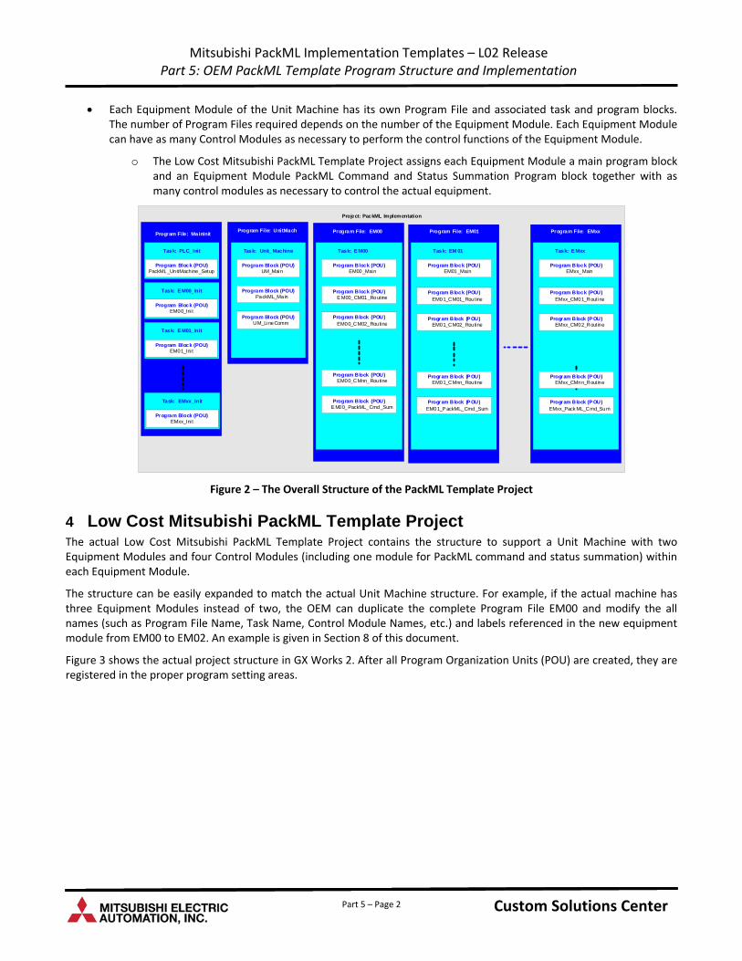
Mitsubishi PackML Implementation Templates – L02 Release Part 5: OEM PackML Template Program Structure and Implementation
Each Equipment Module of the Unit Machine has its own Program File and associated task and program blocks. The number of Program Files required depends on the number of the Equipment Module. Each Equipment Module can have as many Control Modules as necessary to perform the control functions of the Equipment Module.
o The Low Cost Mitsubishi PackML Template Project assigns each Equipment Module a main program block and an Equipment Module PackML Command and Status Summation Program block together with as many control modules as necessary to control the actual equipment.
Project: PackML Implementation
Program File: MainInit
Task: PLC_Init
Program Block (POU)PackML_UnitMach ine_Setup
Program File: UnitMach
Task: Unit_Machine
Program Block (POU) UM_LineComm
Program Block (POU) PackML_Main
Program Block (POU) UM_Main
Task: E M00
Program Block (POU) EM00_CMnn_Routine
Program Block (POU) E M00_CM01_Routine
Program Block (POU) EM00_Main
Program Block (POU) EM00_CM02_Routine
Program Block (POU) E M00_PackML_Cmd_Sum
Program File: EM00
Task: EM 01
Program Block (P OU) EM01_CMnn_Routine
Program Block (POU) EM01_CM01_Routine
Program Block (POU) EM01_Main
Program Block (P OU) EM01_CM02_Routine
Program Block (P OU) EM01_P ackML_Cmd_Sum
Program File: EM01
Task: E Mxx
Program Block (P OU) EMxx_CMnn_Routine
Program Block (POU) EMxx_CM01_Routine
Program Block (POU) EMxx_Main
Program Block (P OU) EMxx_CM02_Routine
Program Block (P OU) EMxx_Pack ML_Cmd_Sum
Program File: EMxx
Task: E M00_Init
Program Block (POU)EM00_Ini t
Task: E M01_Init
Program Block (POU)EM01_Ini t
Task: EMxx_Init
Program Block (POU)EMxx_Ini t
Figure 2 – The Overall Structure of the PackML Template Project
4 Low Cost Mitsubishi PackML Template Project The actual Low Cost Mitsubishi PackML Template Project contains the structure to support a Unit Machine with two Equipment Modules and four Control Modules (including one module for PackML command and status summation) within each Equipment Module.
The structure can be easily expanded to match the actual Unit Machine structure. For example, if the actual machine has three Equipment Modules instead of two, the OEM can duplicate the complete Program File EM00 and modify the all names (such as Program File Name, Task Name, Control Module Names, etc.) and labels referenced in the new equipment module from EM00 to EM02. An example is given in Section 8 of this document.
Figure 3 shows the actual project structure in GX Works 2. After all Program Organization Units (POU) are created, they are registered in the proper program setting areas.
Custom Solutions Center Custom Solutions Center Custom Solutions Center Part 5 – Page 2
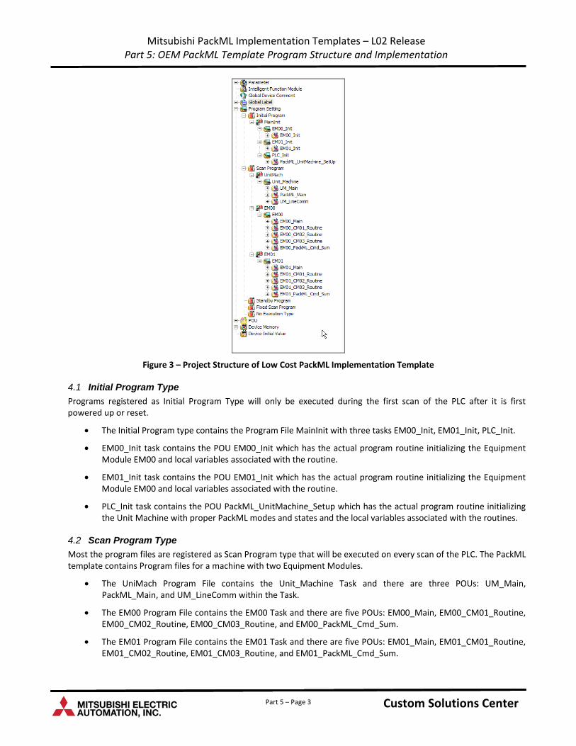
Mitsubishi PackML Implementation Templates – L02 Release Part 5: OEM PackML Template Program Structure and Implementation
Figure 3 – Project Structure of Low Cost PackML Implementation Template
4.1 Initial Program Type
Programs registered as Initial Program Type will only be executed during the first scan of the PLC after it is first powered up or reset.
The Initial Program type contains the Program File MainInit with three tasks EM00_Init, EM01_Init, PLC_Init.
EM00_Init task contains the POU EM00_Init which has the actual program routine initializing the Equipment Module EM00 and local variables associated with the routine.
EM01_Init task contains the POU EM01_Init which has the actual program routine initializing the Equipment Module EM00 and local variables associated with the routine.
PLC_Init task contains the POU PackML_UnitMachine_Setup which has the actual program routine initializing the Unit Machine with proper PackML modes and states and the local variables associated with the routines.
4.2 Scan Program Type
Most the program files are registered as Scan Program type that will be executed on every scan of the PLC. The PackML template contains Program files for a machine with two Equipment Modules.
The UniMach Program File contains the Unit_Machine Task and there are three POUs: UM_Main, PackML_Main, and UM_LineComm within the Task.
The EM00 Program File contains the EM00 Task and there are five POUs: EM00_Main, EM00_CM01_Routine, EM00_CM02_Routine, EM00_CM03_Routine, and EM00_PackML_Cmd_Sum.
The EM01 Program File contains the EM01 Task and there are five POUs: EM01_Main, EM01_CM01_Routine, EM01_CM02_Routine, EM01_CM03_Routine, and EM01_PackML_Cmd_Sum.
Custom Solutions Center Custom Solutions Center Custom Solutions Center Part 5 – Page 3
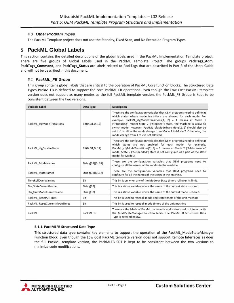
Mitsubishi PackML Implementation Templates – L02 Release Part 5: OEM PackML Template Program Structure and Implementation
4.3 Other Program Types
The PackML Template project does not use the Standby, Fixed Scan, and No Execution Program Types.
5 PackML Global Labels This section contains the detailed descriptions of the global labels used in the PackML Implementation Template project. There are five groups of Global Labels used in the PackML Template Project. The groups PackTags_Adm, PackTags_Command, and PackTags_Status are labels related to PackTags that are described in Part 3 of the Users Guide and will not be described in this document.
5.1 PackML_FB Group
This group contains global labels that are critical to the operation of PackML Core function blocks. The Structured Data Types PackMLFB is defined to support the core PackML FB operations. Even though the Low Cost PackML template version does not support as many modes as the full PackML template version, the PackML_FB Group is kept to be consistent between the two versions.
Variable Label Data Type Description
PackML_cfgModeTransitions Bit(0..31,0..17)
These are the configuration variables that OEM programs need to define at which states where mode transitions are allowed for each mode. For example, PackML_cfgModeTransitions[1, 2] = 1 means at Mode 1 (“Producing” mode) State 2 (“Stopped”) state, the machine is allow to switch mode. However, PackML_cfgModeTransitions[2, 2] should also be set to 1 to allow the mode change from Mode 1 to Mode 2. Otherwise, the mode change from 1 to 2 is not allowed.
PackML_cfgDisableStates Bit(0..31,0..17)
These are the configuration variables that OEM programs need to define at which states are not enabled for each mode. For example, PackML_cfgModeTransitions[2, 5] = 1 means at Mode 2 (“Maintenance” mode) State 5 (“Suspended”) state is not configured as a part of the state model for Mode 2.
PackML_ModeNames String(32)(0..31) These are the configuration variables that OEM programs need to configure all the names of the modes in the machine.
PackML_StateNames String(32)(0..17) These are the configuration variables that OEM programs need to configure for all the names of the states in the machine.
TimeRollOverWarning Bit This bit is on when any of the Mode or State timers roll over its limit.
Sta_StateCurrentName String(32) This is a status variable where the name of the current state is stored.
Sta_UnitModeCurrentName String(32) This is a status variable where the name of the current mode is stored.
PackML_ResetAllTimes Bit This bit is used to reset all mode and state timers of the unit machine
PackML_ResetCurrentModeTimes Bit This bit is used to reset all mode timers of the unit machine
PackML PackMLFB These are the labels of PackML commands and status used to interact with the ModeStateManager function block. The PackMLFB Structured Data Type is detailed below.
5.1.1. PackMLFB Structured Data Type
This structured data type contains key elements to support the operation of the PackML_ModeStateManager Function Block. Even though the Low Cost PackML template version does not support Remote Interfaces as does the full PackML template version, the PackMLFB SDT is kept to be consistent between the two versions to minimize code modifications.
Custom Solutions Center Custom Solutions Center Custom Solutions Center Part 5 – Page 4
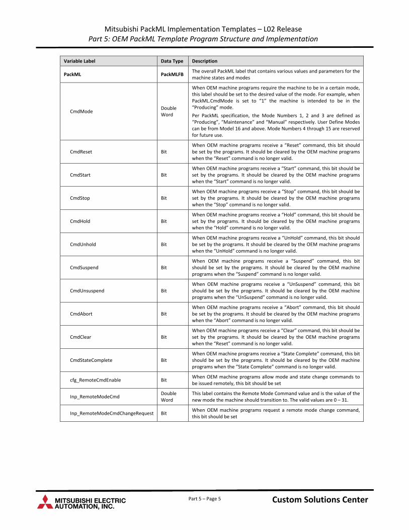
Mitsubishi PackML Implementation Templates – L02 Release Part 5: OEM PackML Template Program Structure and Implementation
Variable Label Data Type Description
PackML PackMLFB The overall PackML label that contains various values and parameters for the machine states and modes
CmdMode Double Word
When OEM machine programs require the machine to be in a certain mode, this label should be set to the desired value of the mode. For example, when PackML.CmdMode is set to “1” the machine is intended to be in the “Producing” mode.
Per PackML specification, the Mode Numbers 1, 2 and 3 are defined as “Producing”, “Maintenance” and “Manual” respectively. User Define Modes can be from Model 16 and above. Mode Numbers 4 through 15 are reserved for future use.
CmdReset Bit When OEM machine programs receive a “Reset” command, this bit should be set by the programs. It should be cleared by the OEM machine programs when the “Reset” command is no longer valid.
CmdStart Bit When OEM machine programs receive a “Start” command, this bit should be set by the programs. It should be cleared by the OEM machine programs when the “Start” command is no longer valid.
CmdStop Bit When OEM machine programs receive a “Stop” command, this bit should be set by the programs. It should be cleared by the OEM machine programs when the “Stop” command is no longer valid.
CmdHold Bit When OEM machine programs receive a “Hold” command, this bit should be set by the programs. It should be cleared by the OEM machine programs when the “Hold” command is no longer valid.
CmdUnhold Bit When OEM machine programs receive a “UnHold” command, this bit should be set by the programs. It should be cleared by the OEM machine programs when the “UnHold” command is no longer valid.
CmdSuspend Bit When OEM machine programs receive a “Suspend” command, this bit should be set by the programs. It should be cleared by the OEM machine programs when the “Suspend” command is no longer valid.
CmdUnsuspend Bit When OEM machine programs receive a “UnSuspend” command, this bit should be set by the programs. It should be cleared by the OEM machine programs when the “UnSuspend” command is no longer valid.
CmdAbort Bit When OEM machine programs receive a “Abort” command, this bit should be set by the programs. It should be cleared by the OEM machine programs when the “Abort” command is no longer valid.
CmdClear Bit When OEM machine programs receive a “Clear” command, this bit should be set by the programs. It should be cleared by the OEM machine programs when the “Reset” command is no longer valid.
CmdStateComplete Bit When OEM machine programs receive a “State Complete” command, this bit should be set by the programs. It should be cleared by the OEM machine programs when the “State Complete” command is no longer valid.
cfg_RemoteCmdEnable Bit When OEM machine programs allow mode and state change commands to be issued remotely, this bit should be set
Inp_RemoteModeCmd Double Word
This label contains the Remote Mode Command value and is the value of the new mode the machine should transition to. The valid values are 0 – 31.
Inp_RemoteModeCmdChangeRequest Bit When OEM machine programs request a remote mode change command, this bit should be set
Custom Solutions Center Custom Solutions Center Custom Solutions Center Part 5 – Page 5
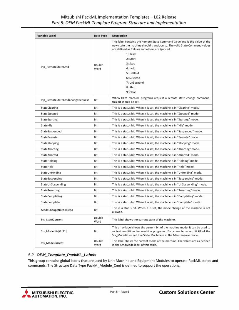
Mitsubishi PackML Implementation Templates – L02 Release Part 5: OEM PackML Template Program Structure and Implementation
Variable Label Data Type Description
Inp_RemoteStateCmd Double Word
This label contains the Remote State Command value and is the value of the new state the machine should transition to. The valid State Command values are defined as follows and others are ignored:
1: Reset
2: Start
3: Stop
4: Hold
5: UnHold
6: Suspend
7: UnSuspend
8: Abort
9: Clear
Inp_RemoteStateCmdChangeRequest Bit When OEM machine programs request a remote state change command, this bit should be set.
StateClearing Bit This is a status bit. When it is set, the machine is in “Clearing” mode.
StateStopped Bit This is a status bit. When it is set, the machine is in “Stopped” mode.
StateStarting Bit This is a status bit. When it is set, the machine is in “Starting” mode.
StateIdle Bit This is a status bit. When it is set, the machine is in “Idle” mode.
StateSuspended Bit This is a status bit. When it is set, the machine is in “Suspended” mode.
StateExecute Bit This is a status bit. When it is set, the machine is in “Execute” mode.
StateStopping Bit This is a status bit. When it is set, the machine is in “Stopping” mode.
StateAborting Bit This is a status bit. When it is set, the machine is in “Aborting” mode.
StateAborted Bit This is a status bit. When it is set, the machine is in “Aborted” mode.
StateHolding Bit This is a status bit. When it is set, the machine is in “Holding” mode.
StateHeld Bit This is a status bit. When it is set, the machine is in “Held” mode.
StateUnHolding Bit This is a status bit. When it is set, the machine is in “UnHolding” mode.
StateSuspending Bit This is a status bit. When it is set, the machine is in “Suspending” mode.
StateUnSuspending Bit This is a status bit. When it is set, the machine is in “UnSuspending” mode.
StateResetting Bit This is a status bit. When it is set, the machine is in “Resetting” mode.
StateCompleting Bit This is a status bit. When it is set, the machine is in “Completing” mode.
StateComplete Bit This is a status bit. When it is set, the machine is in “Complete” mode.
ModeChangeNotAllowed Bit This is a status bit. When it is set, the mode change of the machine is not allowed.
Sts_StateCurrent Double Word
This label shows the current state of the machine.
Sts_Modebits[0..31] Bit This array label shows the current bit of the machine mode. It can be used to as test conditions for machine programs. For example, when bit #2 of the Sts_ModeBits is set, the State Machine is in the Maintenance mode.
Sts_ModeCurrent Double Word
This label shows the current mode of the machine. The values are as defined in the CmdMode label of this table.
5.2 OEM_Template_PackML_Labels
This group contains global labels that are used by Unit Machine and Equipment Modules to operate PackML states and commands. The Structure Data Type PackM_Module_Cmd is defined to support the operations.
Custom Solutions Center Custom Solutions Center Custom Solutions Center Part 5 – Page 6
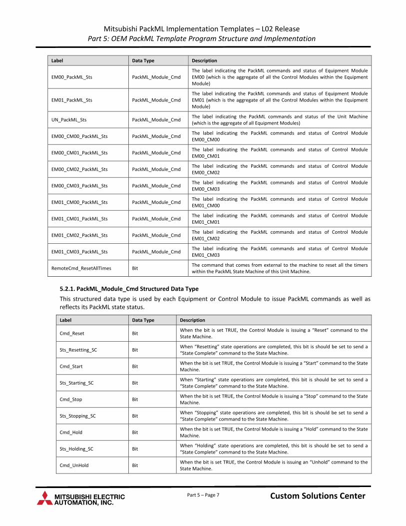
Mitsubishi PackML Implementation Templates – L02 Release Part 5: OEM PackML Template Program Structure and Implementation
Label Data Type Description
EM00_PackML_Sts PackML_Module_Cmd The label indicating the PackML commands and status of Equipment Module EM00 (which is the aggregate of all the Control Modules within the Equipment Module)
EM01_PackML_Sts PackML_Module_Cmd The label indicating the PackML commands and status of Equipment Module EM01 (which is the aggregate of all the Control Modules within the Equipment Module)
UN_PackML_Sts PackML_Module_Cmd The label indicating the PackML commands and status of the Unit Machine (which is the aggregate of all Equipment Modules)
EM00_CM00_PackML_Sts PackML_Module_Cmd The label indicating the PackML commands and status of Control Module EM00_CM00
EM00_CM01_PackML_Sts PackML_Module_Cmd The label indicating the PackML commands and status of Control Module EM00_CM01
EM00_CM02_PackML_Sts PackML_Module_Cmd The label indicating the PackML commands and status of Control Module EM00_CM02
EM00_CM03_PackML_Sts PackML_Module_Cmd The label indicating the PackML commands and status of Control Module EM00_CM03
EM01_CM00_PackML_Sts PackML_Module_Cmd The label indicating the PackML commands and status of Control Module EM01_CM00
EM01_CM01_PackML_Sts PackML_Module_Cmd The label indicating the PackML commands and status of Control Module EM01_CM01
EM01_CM02_PackML_Sts PackML_Module_Cmd The label indicating the PackML commands and status of Control Module EM01_CM02
EM01_CM03_PackML_Sts PackML_Module_Cmd The label indicating the PackML commands and status of Control Module EM01_CM03
RemoteCmd_ResetAllTimes Bit The command that comes from external to the machine to reset all the timers within the PackML State Machine of this Unit Machine.
5.2.1. PackML_Module_Cmd Structured Data Type
This structured data type is used by each Equipment or Control Module to issue PackML commands as well as reflects its PackML state status.
Label Data Type Description
Cmd_Reset Bit When the bit is set TRUE, the Control Module is issuing a “Reset” command to the State Machine.
Sts_Resetting_SC Bit When “Resetting” state operations are completed, this bit is should be set to send a “State Complete” command to the State Machine.
Cmd_Start Bit When the bit is set TRUE, the Control Module is issuing a “Start” command to the State Machine.
Sts_Starting_SC Bit When “Starting” state operations are completed, this bit is should be set to send a “State Complete” command to the State Machine.
Cmd_Stop Bit When the bit is set TRUE, the Control Module is issuing a “Stop” command to the State Machine.
Sts_Stopping_SC Bit When “Stopping” state operations are completed, this bit is should be set to send a “State Complete” command to the State Machine.
Cmd_Hold Bit When the bit is set TRUE, the Control Module is issuing a “Hold” command to the State Machine.
Sts_Holding_SC Bit When “Holding” state operations are completed, this bit is should be set to send a “State Complete” command to the State Machine.
Cmd_UnHold Bit When the bit is set TRUE, the Control Module is issuing an “Unhold” command to the State Machine.
Custom Solutions Center Custom Solutions Center Custom Solutions Center Part 5 – Page 7
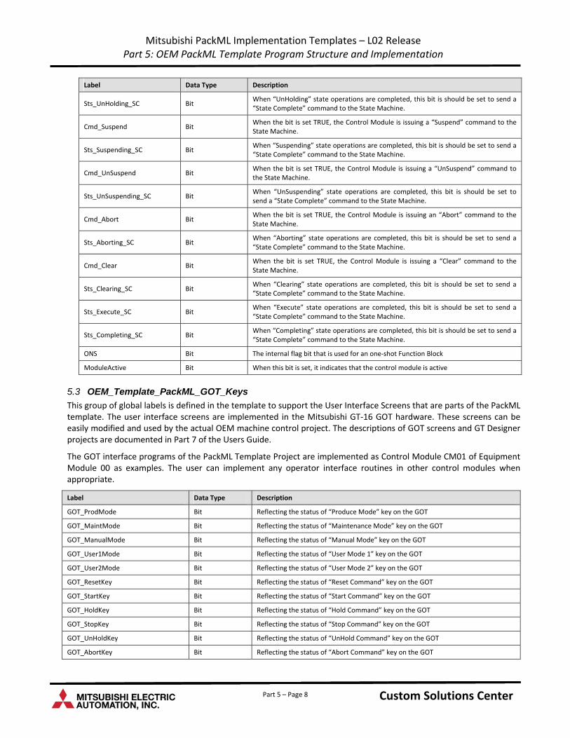
Mitsubishi PackML Implementation Templates – L02 Release Part 5: OEM PackML Template Program Structure and Implementation
Label Data Type Description
Sts_UnHolding_SC Bit When “UnHolding” state operations are completed, this bit is should be set to send a “State Complete” command to the State Machine.
Cmd_Suspend Bit When the bit is set TRUE, the Control Module is issuing a “Suspend” command to the State Machine.
Sts_Suspending_SC Bit When “Suspending” state operations are completed, this bit is should be set to send a “State Complete” command to the State Machine.
Cmd_UnSuspend Bit When the bit is set TRUE, the Control Module is issuing a “UnSuspend” command to the State Machine.
Sts_UnSuspending_SC Bit When “UnSuspending” state operations are completed, this bit is should be set to send a “State Complete” command to the State Machine.
Cmd_Abort Bit When the bit is set TRUE, the Control Module is issuing an “Abort” command to the State Machine.
Sts_Aborting_SC Bit When “Aborting” state operations are completed, this bit is should be set to send a “State Complete” command to the State Machine.
Cmd_Clear Bit When the bit is set TRUE, the Control Module is issuing a “Clear” command to the State Machine.
Sts_Clearing_SC Bit When “Clearing” state operations are completed, this bit is should be set to send a “State Complete” command to the State Machine.
Sts_Execute_SC Bit When “Execute” state operations are completed, this bit is should be set to send a “State Complete” command to the State Machine.
Sts_Completing_SC Bit When “Completing” state operations are completed, this bit is should be set to send a “State Complete” command to the State Machine.
ONS Bit The internal flag bit that is used for an one‐shot Function Block
ModuleActive Bit When this bit is set, it indicates that the control module is active
5.3 OEM_Template_PackML_GOT_Keys
This group of global labels is defined in the template to support the User Interface Screens that are parts of the PackML template. The user interface screens are implemented in the Mitsubishi GT‐16 GOT hardware. These screens can be easily modified and used by the actual OEM machine control project. The descriptions of GOT screens and GT Designer projects are documented in Part 7 of the Users Guide.
The GOT interface programs of the PackML Template Project are implemented as Control Module CM01 of Equipment Module 00 as examples. The user can implement any operator interface routines in other control modules when appropriate.
Label Data Type Description
GOT_ProdMode Bit Reflecting the status of “Produce Mode” key on the GOT
GOT_MaintMode Bit Reflecting the status of “Maintenance Mode” key on the GOT
GOT_ManualMode Bit Reflecting the status of “Manual Mode” key on the GOT
GOT_User1Mode Bit Reflecting the status of “User Mode 1” key on the GOT
GOT_User2Mode Bit Reflecting the status of “User Mode 2” key on the GOT
GOT_ResetKey Bit Reflecting the status of “Reset Command” key on the GOT
GOT_StartKey Bit Reflecting the status of “Start Command” key on the GOT
GOT_HoldKey Bit Reflecting the status of “Hold Command” key on the GOT
GOT_StopKey Bit Reflecting the status of “Stop Command” key on the GOT
GOT_UnHoldKey Bit Reflecting the status of “UnHold Command” key on the GOT
GOT_AbortKey Bit Reflecting the status of “Abort Command” key on the GOT
Custom Solutions Center Custom Solutions Center Custom Solutions Center Part 5 – Page 8
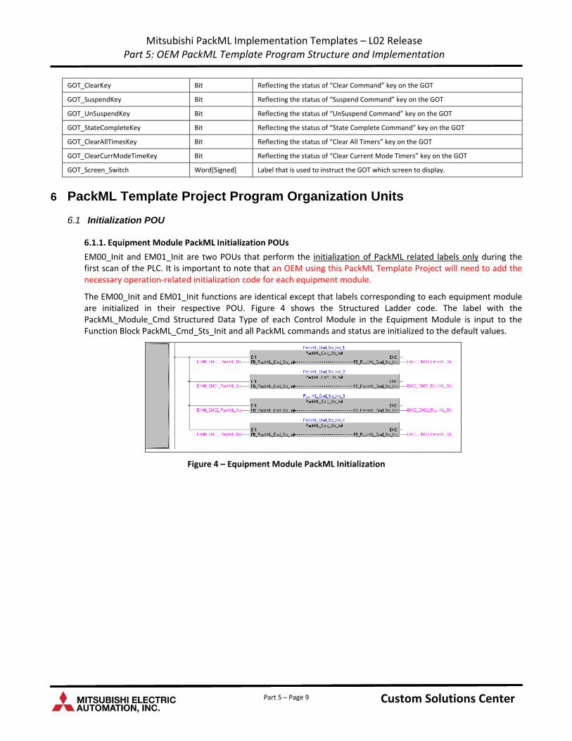
Mitsubishi PackML Implementation Templates – L02 Release Part 5: OEM PackML Template Program Structure and Implementation
GOT_ClearKey Bit Reflecting the status of “Clear Command” key on the GOT
GOT_SuspendKey Bit Reflecting the status of “Suspend Command” key on the GOT
GOT_UnSuspendKey Bit Reflecting the status of “UnSuspend Command” key on the GOT
GOT_StateCompleteKey Bit Reflecting the status of “State Complete Command” key on the GOT
GOT_ClearAllTimesKey Bit Reflecting the status of “Clear All Timers” key on the GOT
GOT_ClearCurrModeTimeKey Bit Reflecting the status of “Clear Current Mode Timers” key on the GOT
GOT_Screen_Switch Word[Signed] Label that is used to instruct the GOT which screen to display.
6 PackML Template Project Program Organization Units
6.1 Initialization POU
6.1.1. Equipment Module PackML Initialization POUs
EM00_Init and EM01_Init are two POUs that perform the initialization of PackML related labels only during the first scan of the PLC. It is important to note that an OEM using this PackML Template Project will need to add the necessary operation‐related initialization code for each equipment module.
The EM00_Init and EM01_Init functions are identical except that labels corresponding to each equipment module are initialized in their respective POU. Figure 4 shows the Structured Ladder code. The label with the PackML_Module_Cmd Structured Data Type of each Control Module in the Equipment Module is input to the Function Block PackML_Cmd_Sts_Init and all PackML commands and status are initialized to the default values.
Figure 4 – Equipment Module PackML Initialization
Custom Solutions Center Custom Solutions Center Custom Solutions Center Part 5 – Page 9
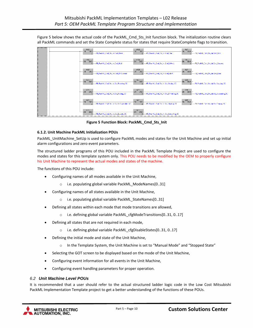
Mitsubishi PackML Implementation Templates – L02 Release Part 5: OEM PackML Template Program Structure and Implementation
Figure 5 below shows the actual code of the PackML_Cmd_Sts_Init function block. The initialization routine clears all PackML commands and set the State Complete status for states that require StateComplete flags to transition.
Figure 5 Function Block: PackML_Cmd_Sts_Init
6.1.2. Unit Machine PackML Initialization POUs
PackML_UnitMachine_SetUp is used to configure PackML modes and states for the Unit Machine and set up initial alarm configurations and zero event parameters.
The structured ladder programs of this POU included in the PackML Template Project are used to configure the modes and states for this template system only. This POU needs to be modified by the OEM to properly configure his Unit Machine to represent the actual modes and states of the machine.
The functions of this POU include:
Configuring names of all modes available in the Unit Machine,
o i.e. populating global variable PackML_ModeNames[0..31]
Configuring names of all states available in the Unit Machine,
o i.e. populating global variable PackML_StateNames[0..31]
Defining all states within each mode that mode transitions are allowed,
o i.e. defining global variable PackML_cfgModeTransitions[0..31, 0..17]
Defining all states that are not required in each mode,
o i.e. defining global variable PackML_cfgDisableStates[0..31, 0..17]
Defining the initial mode and state of the Unit Machine,
o In the Template System, the Unit Machine is set to “Manual Mode” and “Stopped State”
Selecting the GOT screen to be displayed based on the mode of the Unit Machine,
Configuring event information for all events in the Unit Machine,
Configuring event handling parameters for proper operation.
6.2 Unit Machine Level POUs
It is recommended that a user should refer to the actual structured ladder logic code in the Low Cost Mitsubishi PackML Implementation Template project to get a better understanding of the functions of these POUs.
Custom Solutions Center Custom Solutions Center Custom Solutions Center Part 5 – Page 10
Mitsubishi PackML Implementation Templates – L02 Release Part 5: OEM PackML Template Program Structure and Implementation
6.2.1. UM_Main
The purpose of this POU is to control the flow of the other routines at the Unit Machine level. It contains all the calls to all other unit machine level POUs.
6.2.2. PackML_Main
This POU operates the PackML state machine and its functions include:
Aggregating PackML commands and status of all equipment modules,
o If there are more than two equipment modules in the Unit Machine, this part of the template routine needs to be modified to include commands and status from the additional equipment modules
Setting proper PackML command or status based on the aggregated results,
Calling the PackML_ModeStateManager function block to set the PackML state machine in the correct mode and state and then clearing the command and status
Calling the PackML_ModeStateTimes function block to accumulate the time in the current mode and state.
6.3 Equipment Module Level POUs
Programs of each Equipment Module are grouped in the Program File EMxx and Task EMxx. In the Template Project, each equipment module contains the main POU, an event control POU, three control module POU’s, and a PackML Command Summation POU. For an actual implementation, the OEM can add or subtract the control module POU’s as appropriate.
6.3.1. EMxx_Main
The purpose of this POU is to control the flow of the other routines at the Equipment Module level. It contains all the calls to all other equipment module level POUs.
6.3.2. EMxx_CMnn_Routine
This POU contains the logic for Control Module nn of this particular equipment module xx. The OEM should incorporate the appropriate control logic in this POU to perform the actual control functions. For an actual implementation, the OEM can add or subtract control module POU’s as appropriate. The names of these POU’s can also be modified to better reflect the actual control module functions, for example, instead of EM00_CM01_Routine, the POU can be named as Filling_Station_HMI_Interface.
In the Mitsubishi PackML Implementation Template project, EM00_CM01_Routine contains the GOT interface routine for PackML state and mode transitions. It takes the key pressed on the GOT and set or reset the proper flags to drive the PackML state machine operations. EM00_CM02_Routine and EM01_CM02_Routine contain the GOT interface routine for simulating events in the Unit Machine through GOT key presses.
6.3.3. EMxx_PackML_Cmd_Sum
The purpose of this POU is to aggregate all PackML related commands and status from all control modules of this particular equipment module.
The consolidated command or status will then be used in the PackML_Main POU to set the command and status at the Unit Machine level.
6.4 POU Scan Order
The scan order of all the POU’s is shown in Figure 6 below:
Custom Solutions Center Custom Solutions Center Custom Solutions Center Part 5 – Page 11
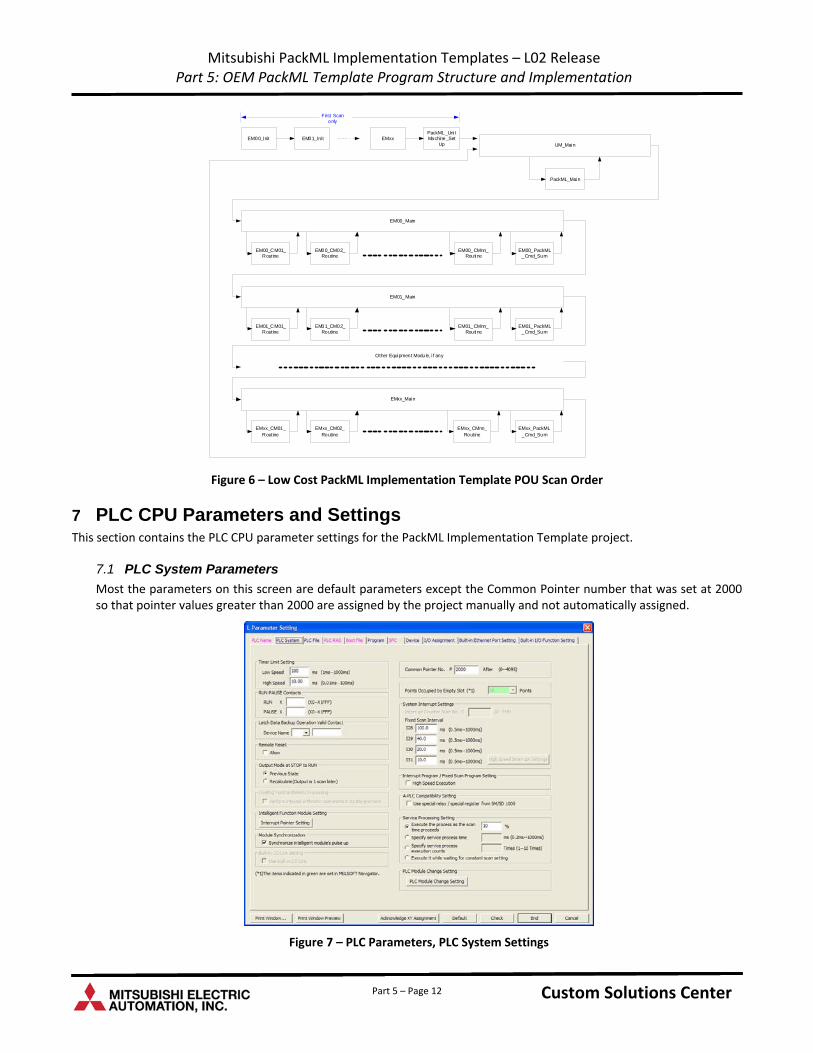
Mitsubishi PackML Implementation Templates – L02 Release Part 5: OEM PackML Template Program Structure and Implementation
First Scanonly
EM00_Init EM01_Ini t EMxxPackML_Uni tMachine_Set
Up
PackML_Main
EM00_CM01_Routine
EM00_CM02_Routine
EM00_CMnn_Routine
EM00_PackML_Cmd_Sum
EM00_Main
UM_Main
EM01_CM01_Routine
EM01_CM02_Routine
EM01_CMnn_Routine
EM01_PackML_Cmd_Sum
EM01_Main
EMxx_CM01_Routine
EMxx_CM02_Routine
EMxx_CMnn_Routine
EMxx_PackML_Cmd_Sum
EMxx_Main
Other Equipment Module, i f any
Figure 6 – Low Cost PackML Implementation Template POU Scan Order
7 PLC CPU Parameters and Settings This section contains the PLC CPU parameter settings for the PackML Implementation Template project.
7.1 PLC System Parameters
Most the parameters on this screen are default parameters except the Common Pointer number that was set at 2000 so that pointer values greater than 2000 are assigned by the project manually and not automatically assigned.
Figure 7 – PLC Parameters, PLC System Settings
Custom Solutions Center Custom Solutions Center Custom Solutions Center Part 5 – Page 12
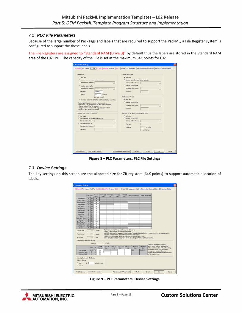
Mitsubishi PackML Implementation Templates – L02 Release Part 5: OEM PackML Template Program Structure and Implementation
7.2 PLC File Parameters
Because of the large number of PackTags and labels that are required to support the PackML, a File Register system is configured to support the these labels.
The File Registers are assigned to “Standard RAM (Drive 3)” by default thus the labels are stored in the Standard RAM area of the L02CPU. The capacity of the File is set at the maximum 64K points for L02.
Figure 8 – PLC Parameters, PLC File Settings
7.3 Device Settings
The key settings on this screen are the allocated size for ZR registers (64K points) to support automatic allocation of labels.
Figure 9 – PLC Parameters, Device Settings
Custom Solutions Center Custom Solutions Center Custom Solutions Center Part 5 – Page 13
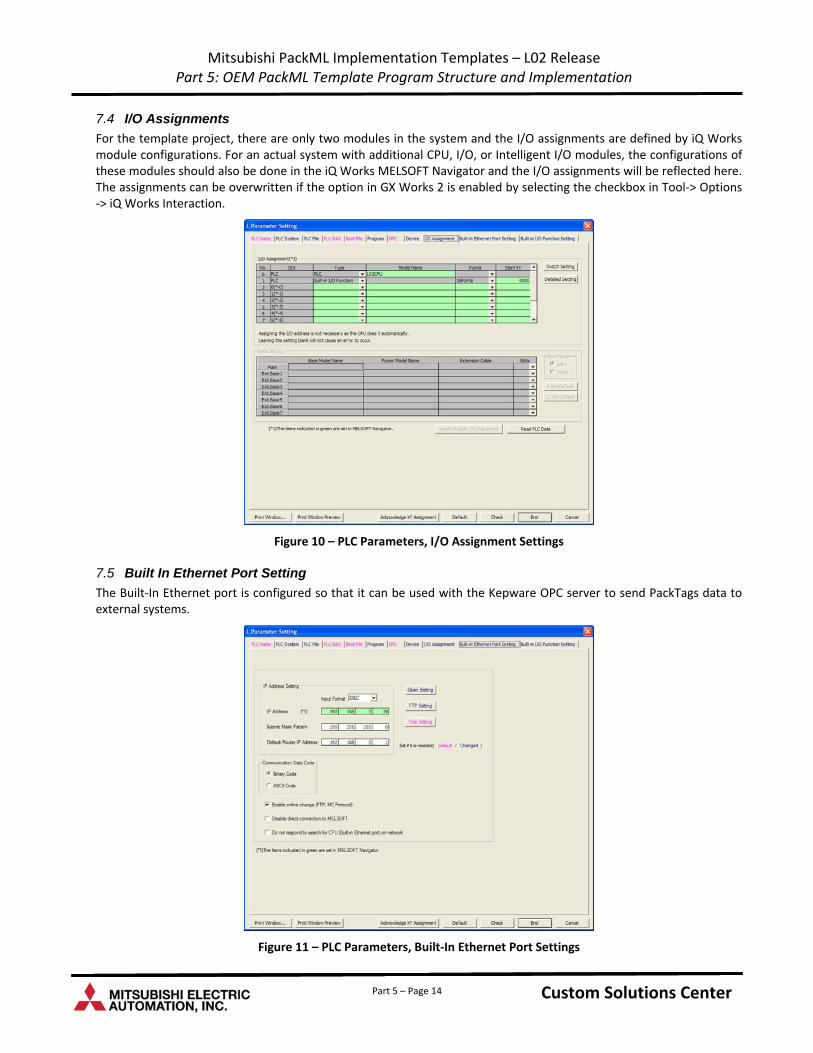
Mitsubishi PackML Implementation Templates – L02 Release Part 5: OEM PackML Template Program Structure and Implementation
7.4 I/O Assignments
For the template project, there are only two modules in the system and the I/O assignments are defined by iQ Works module configurations. For an actual system with additional CPU, I/O, or Intelligent I/O modules, the configurations of these modules should also be done in the iQ Works MELSOFT Navigator and the I/O assignments will be reflected here. The assignments can be overwritten if the option in GX Works 2 is enabled by selecting the checkbox in Tool‐> Options ‐> iQ Works Interaction.
Figure 10 – PLC Parameters, I/O Assignment Settings
7.5 Built In Ethernet Port Setting
The Built‐In Ethernet port is configured so that it can be used with the Kepware OPC server to send PackTags data to external systems.
Figure 11 – PLC Parameters, Built‐In Ethernet Port Settings
Custom Solutions Center Custom Solutions Center Custom Solutions Center Part 5 – Page 14
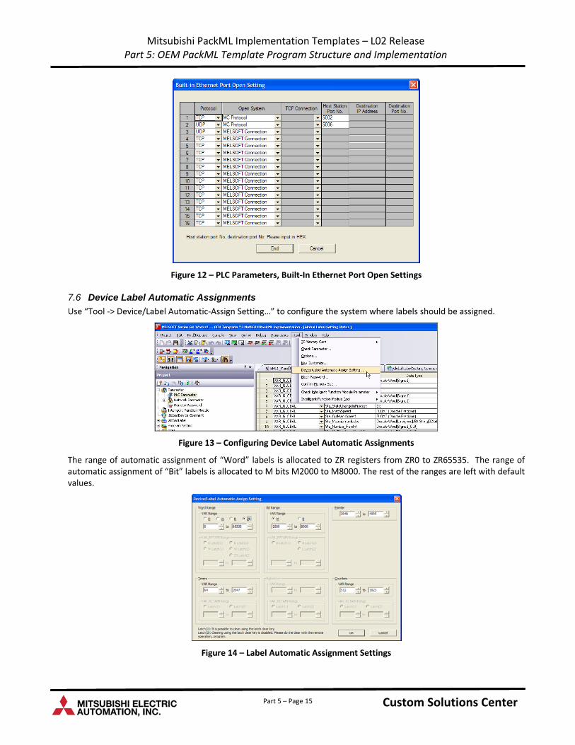
Mitsubishi PackML Implementation Templates – L02 Release Part 5: OEM PackML Template Program Structure and Implementation
Figure 12 – PLC Parameters, Built‐In Ethernet Port Open Settings
7.6 Device Label Automatic Assignments
Use “Tool ‐> Device/Label Automatic‐Assign Setting…” to configure the system where labels should be assigned.
Figure 13 – Configuring Device Label Automatic Assignments
The range of automatic assignment of “Word” labels is allocated to ZR registers from ZR0 to ZR65535. The range of automatic assignment of “Bit” labels is allocated to M bits M2000 to M8000. The rest of the ranges are left with default values.
Figure 14 – Label Automatic Assignment Settings
Custom Solutions Center Custom Solutions Center Custom Solutions Center Part 5 – Page 15
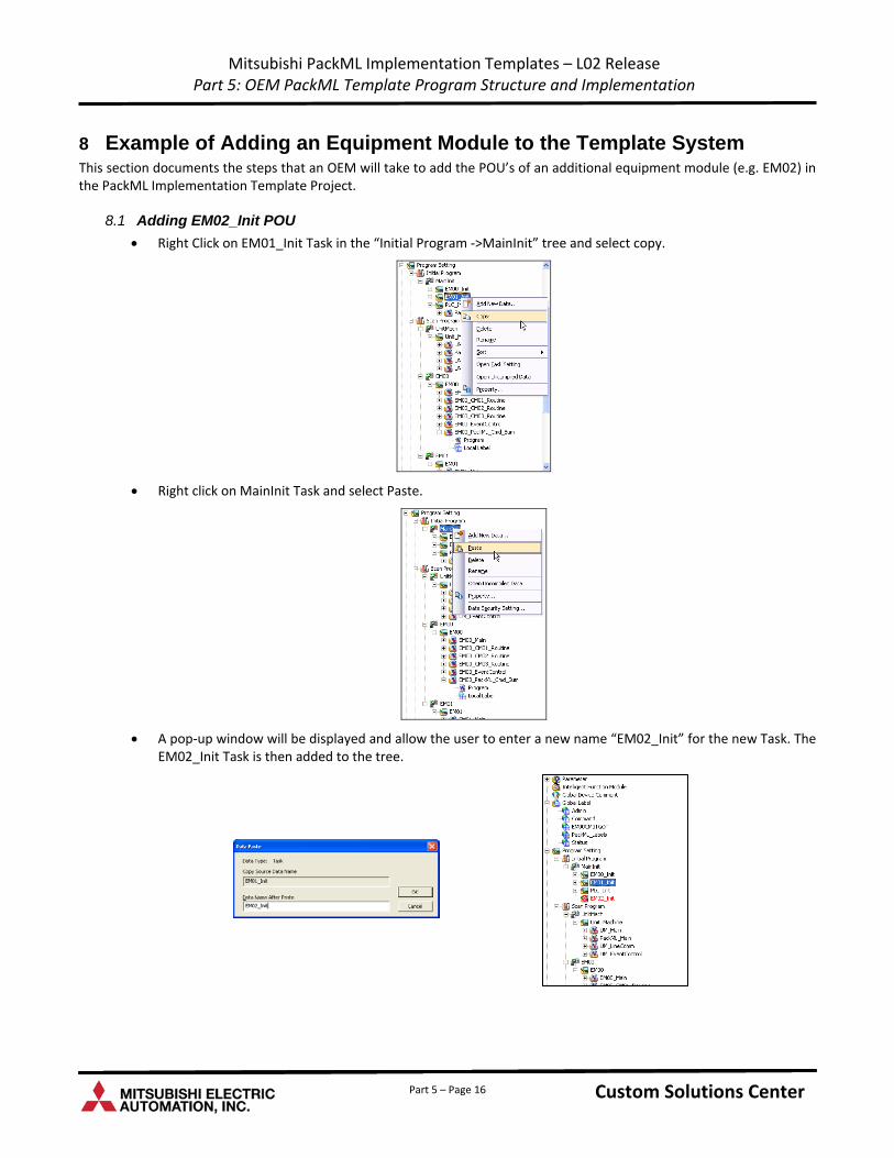
Mitsubishi PackML Implementation Templates – L02 Release Part 5: OEM PackML Template Program Structure and Implementation
8 Example of Adding an Equipment Module to the Template System This section documents the steps that an OEM will take to add the POU’s of an additional equipment module (e.g. EM02) in the PackML Implementation Template Project.
8.1 Adding EM02_Init POU
Right Click on EM01_Init Task in the “Initial Program ‐>MainInit” tree and select copy.
Right click on MainInit Task and select Paste.
A pop‐up window will be displayed and allow the user to enter a new name “EM02_Init” for the new Task. The EM02_Init Task is then added to the tree.
Custom Solutions Center Custom Solutions Center Custom Solutions Center Part 5 – Page 16
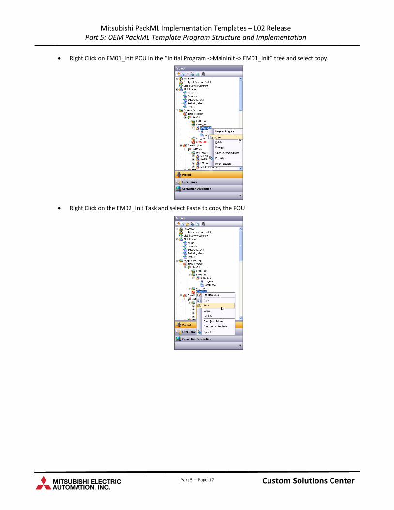
Mitsubishi PackML Implementation Templates – L02 Release Part 5: OEM PackML Template Program Structure and Implementation
Right Click on EM01_Init POU in the “Initial Program ‐>MainInit ‐> EM01_Init” tree and select copy.
Right Click on the EM02_Init Task and select Paste to copy the POU
Custom Solutions Center Custom Solutions Center Custom Solutions Center Part 5 – Page 17
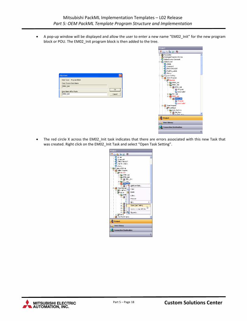
Mitsubishi PackML Implementation Templates – L02 Release Part 5: OEM PackML Template Program Structure and Implementation
A pop‐up window will be displayed and allow the user to enter a new name “EM02_Init” for the new program block or POU. The EM02_Init program block is then added to the tree.
The red circle X across the EM02_Init task indicates that there are errors associated with this new Task that was created. Right click on the EM02_Init Task and select “Open Task Setting”.
Custom Solutions Center Custom Solutions Center Custom Solutions Center Part 5 – Page 18
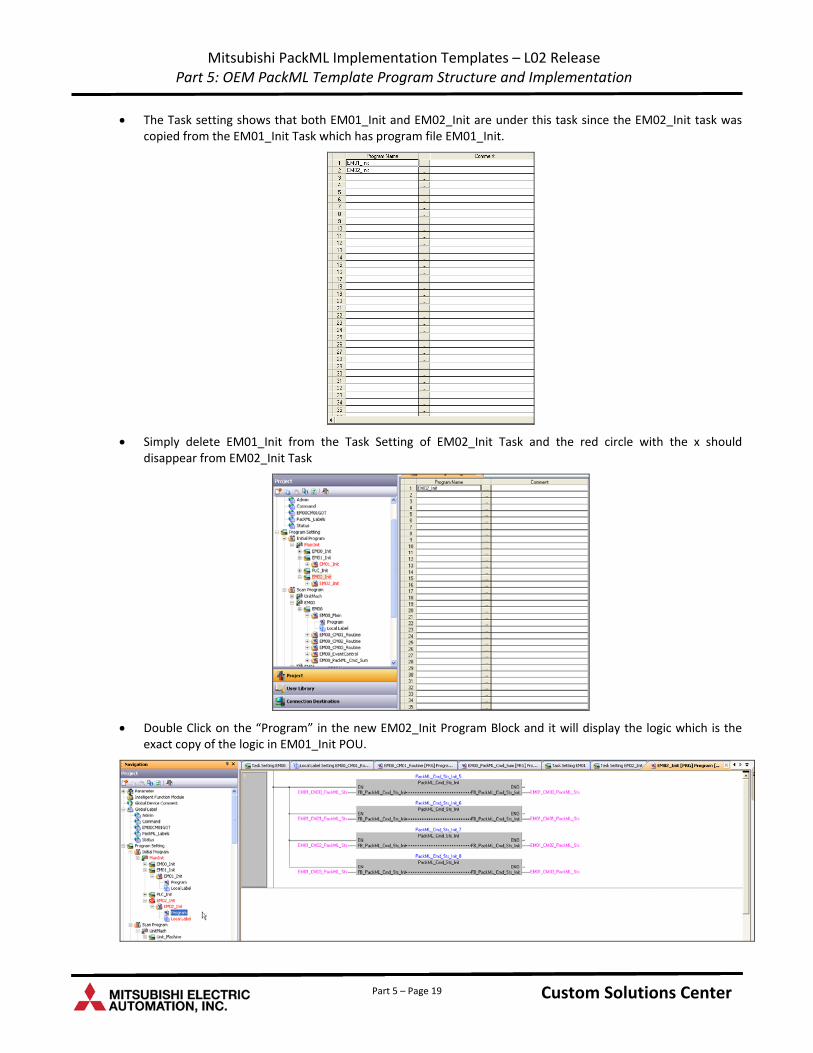
Mitsubishi PackML Implementation Templates – L02 Release Part 5: OEM PackML Template Program Structure and Implementation
The Task setting shows that both EM01_Init and EM02_Init are under this task since the EM02_Init task was copied from the EM01_Init Task which has program file EM01_Init.
Simply delete EM01_Init from the Task Setting of EM02_Init Task and the red circle with the x should disappear from EM02_Init Task
Double Click on the “Program” in the new EM02_Init Program Block and it will display the logic which is the exact copy of the logic in EM01_Init POU.
Custom Solutions Center Custom Solutions Center Custom Solutions Center Part 5 – Page 19
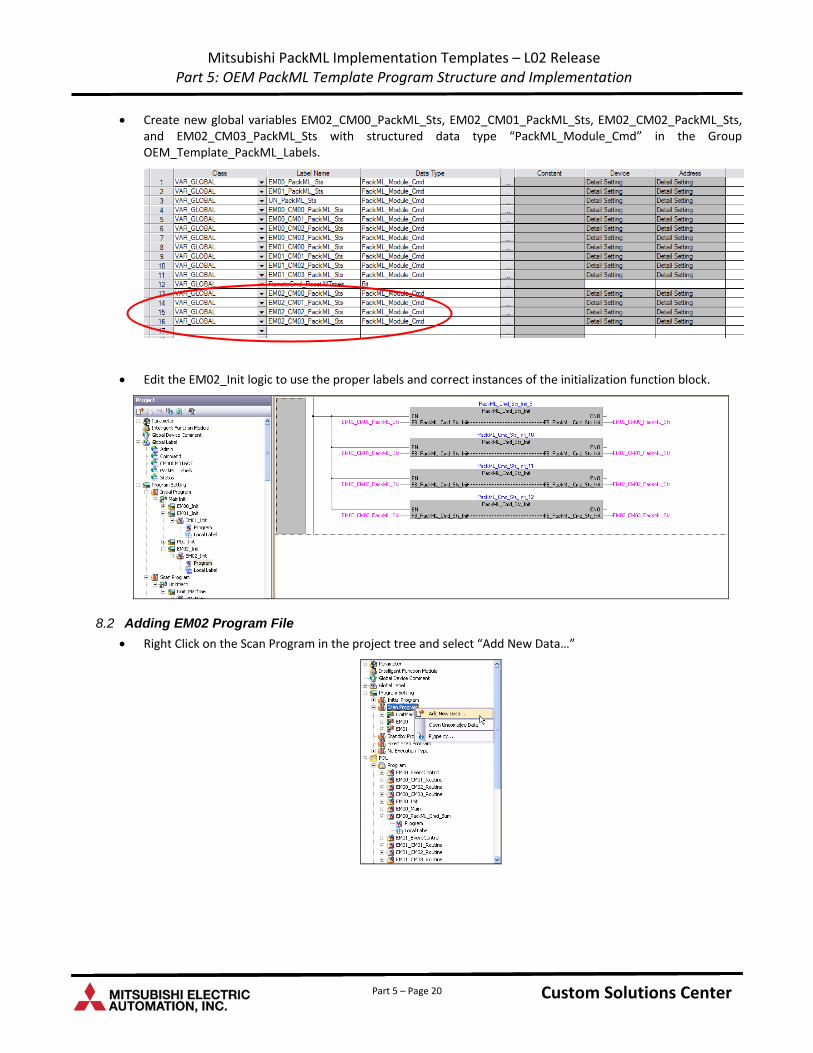
Mitsubishi PackML Implementation Templates – L02 Release Part 5: OEM PackML Template Program Structure and Implementation
Create new global variables EM02_CM00_PackML_Sts, EM02_CM01_PackML_Sts, EM02_CM02_PackML_Sts, and EM02_CM03_PackML_Sts with structured data type “PackML_Module_Cmd” in the Group OEM_Template_PackML_Labels.
Edit the EM02_Init logic to use the proper labels and correct instances of the initialization function block.
8.2 Adding EM02 Program File
Right Click on the Scan Program in the project tree and select “Add New Data…”
Custom Solutions Center Custom Solutions Center Custom Solutions Center Part 5 – Page 20
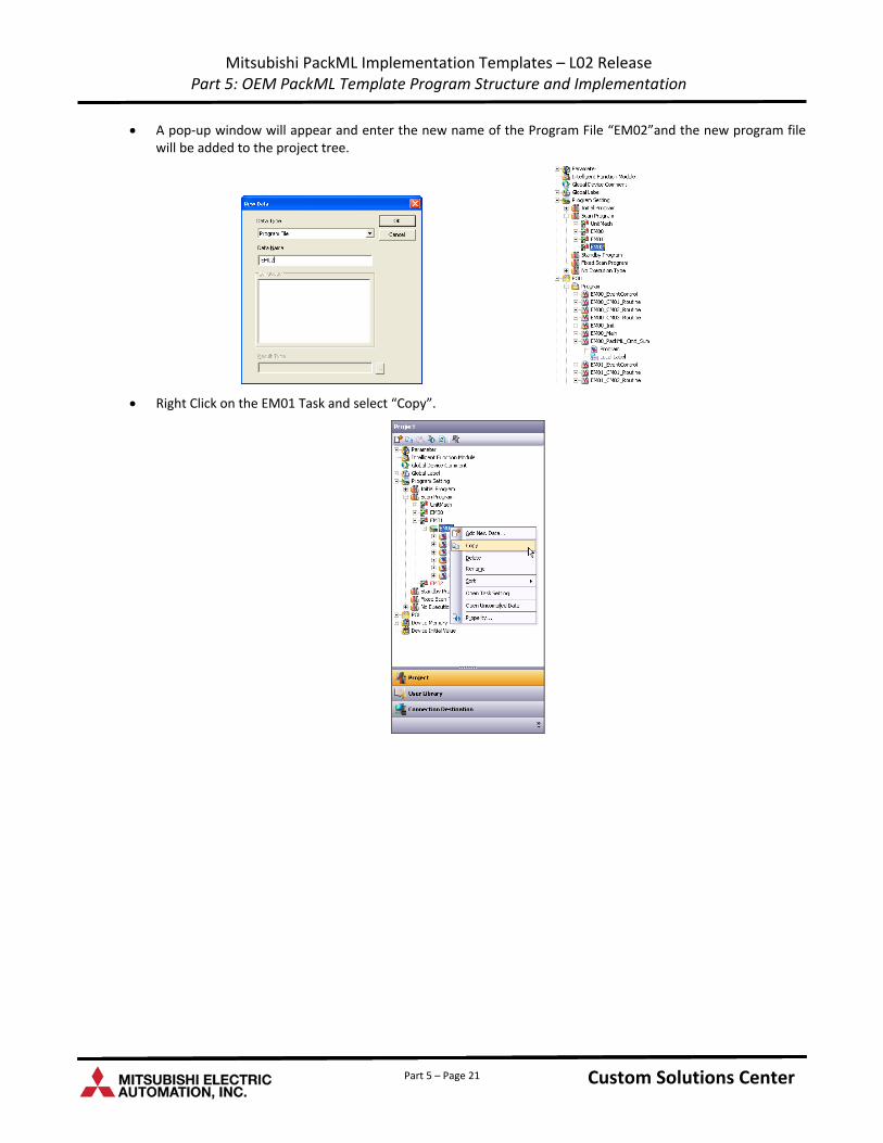
Mitsubishi PackML Implementation Templates – L02 Release Part 5: OEM PackML Template Program Structure and Implementation
A pop‐up window will appear and enter the new name of the Program File “EM02”and the new program file will be added to the project tree.
Right Click on the EM01 Task and select “Copy”.
Custom Solutions Center Custom Solutions Center Custom Solutions Center Part 5 – Page 21
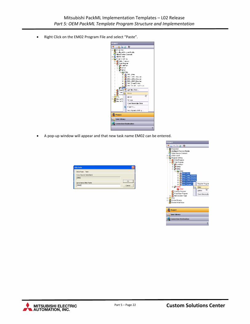
Mitsubishi PackML Implementation Templates – L02 Release Part 5: OEM PackML Template Program Structure and Implementation
Right Click on the EM02 Program File and select “Paste”.
A pop‐up window will appear and that new task name EM02 can be entered.
Custom Solutions Center Custom Solutions Center Custom Solutions Center Part 5 – Page 22
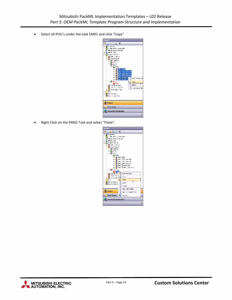
Mitsubishi PackML Implementation Templates – L02 Release Part 5: OEM PackML Template Program Structure and Implementation
Select all POU’s under the task EM01 and click “Copy”
Right Click on the EM02 Task and select “Paste”.
Custom Solutions Center Custom Solutions Center Custom Solutions Center Part 5 – Page 23
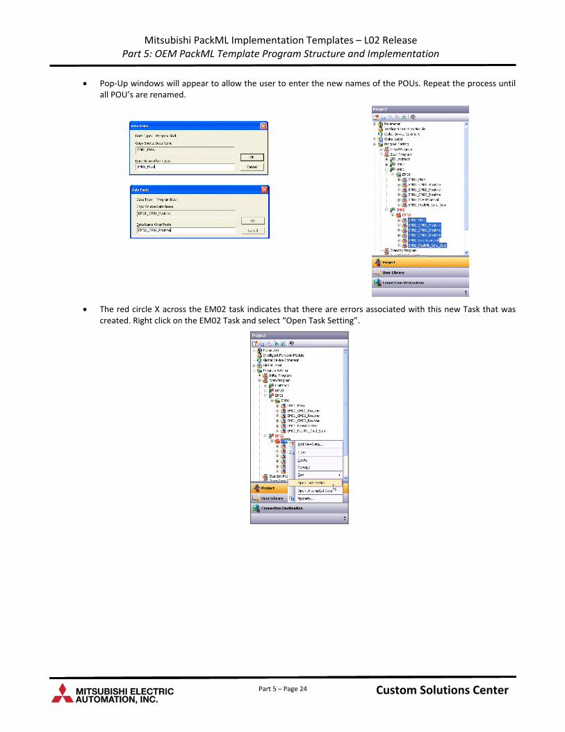
Mitsubishi PackML Implementation Templates – L02 Release Part 5: OEM PackML Template Program Structure and Implementation
Pop‐Up windows will appear to allow the user to enter the new names of the POUs. Repeat the process until all POU’s are renamed.
The red circle X across the EM02 task indicates that there are errors associated with this new Task that was created. Right click on the EM02 Task and select “Open Task Setting”.
Custom Solutions Center Custom Solutions Center Custom Solutions Center Part 5 – Page 24
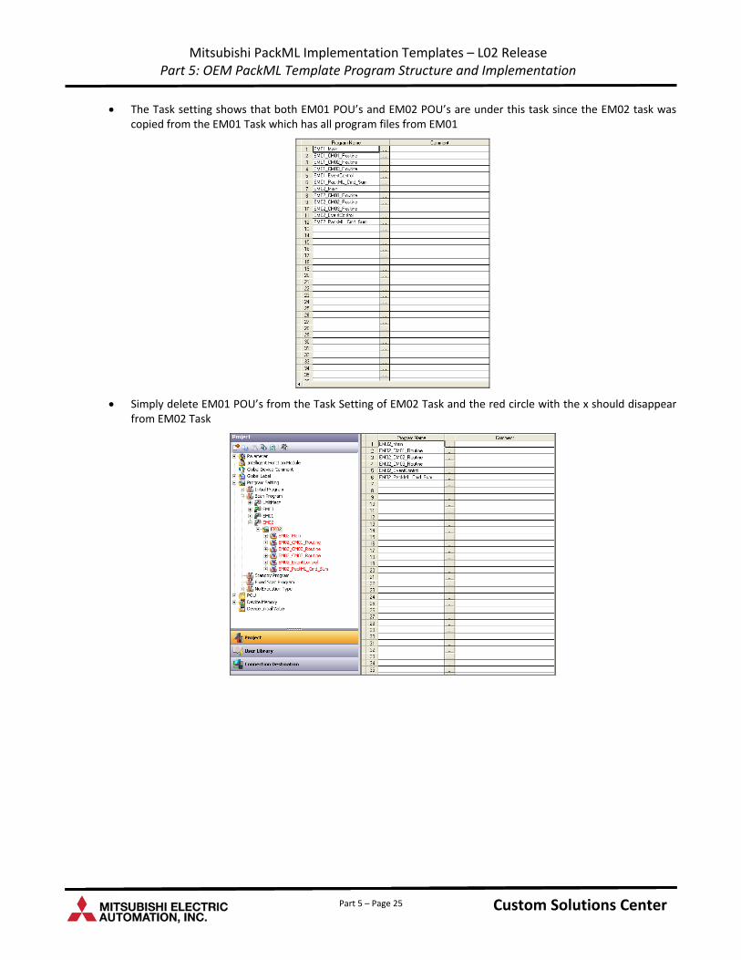
Mitsubishi PackML Implementation Templates – L02 Release Part 5: OEM PackML Template Program Structure and Implementation
The Task setting shows that both EM01 POU’s and EM02 POU’s are under this task since the EM02 task was copied from the EM01 Task which has all program files from EM01
Simply delete EM01 POU’s from the Task Setting of EM02 Task and the red circle with the x should disappear from EM02 Task
Custom Solutions Center Custom Solutions Center Custom Solutions Center Part 5 – Page 25
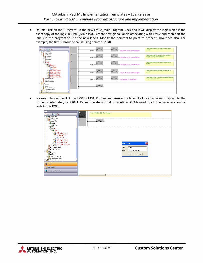
Mitsubishi PackML Implementation Templates – L02 Release Part 5: OEM PackML Template Program Structure and Implementation
Double Click on the “Program” in the new EM02_Main Program Block and it will display the logic which is the exact copy of the logic in EM01_Main POU. Create new global labels associating with EM02 and then edit the labels in the program to use the new labels. Modify the pointers to point to proper subroutines also. For example, the first subroutine call is using pointer P2040.
For example, double click the EM02_CM01_Routine and ensure the label block pointer value is revised to the proper pointer label, i.e. P2041. Repeat the steps for all subroutines. OEMs need to add the necessary control code in this POU.
Custom Solutions Center Custom Solutions Center Custom Solutions Center Part 5 – Page 26
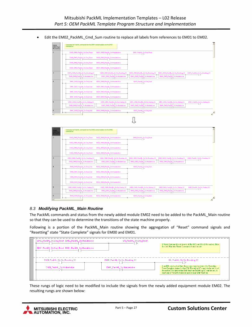
Mitsubishi PackML Implementation Templates – L02 Release Part 5: OEM PackML Template Program Structure and Implementation
Edit the EM02_PackML_Cmd_Sum routine to replace all labels from references to EM01 to EM02.
8.3 Modifying PackML_Main Routine
The PackML commands and status from the newly added module EM02 need to be added to the PackML_Main routine so that they can be used to determine the transitions of the state machine properly.
Following is a portion of the PackML_Main routine showing the aggregation of “Reset” command signals and “Resetting” state “State Complete” signals for EM00 and EM01.
These rungs of logic need to be modified to include the signals from the newly added equipment module EM02. The resulting rungs are shown below:
Custom Solutions Center Custom Solutions Center Custom Solutions Center Part 5 – Page 27
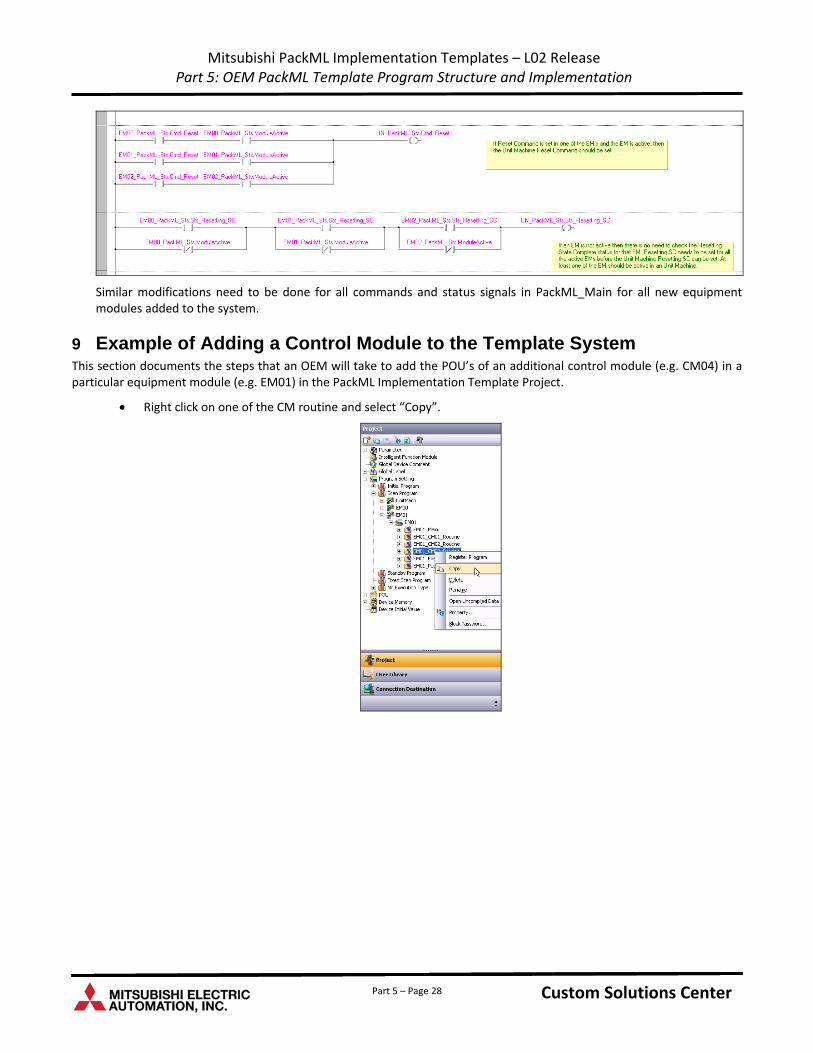
Mitsubishi PackML Implementation Templates – L02 Release Part 5: OEM PackML Template Program Structure and Implementation
Similar modifications need to be done for all commands and status signals in PackML_Main for all new equipment modules added to the system.
9 Example of Adding a Control Module to the Template System This section documents the steps that an OEM will take to add the POU’s of an additional control module (e.g. CM04) in a particular equipment module (e.g. EM01) in the PackML Implementation Template Project.
Right click on one of the CM routine and select “Copy”.
Custom Solutions Center Custom Solutions Center Custom Solutions Center Part 5 – Page 28
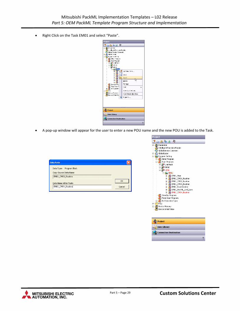
Mitsubishi PackML Implementation Templates – L02 Release Part 5: OEM PackML Template Program Structure and Implementation
Right Click on the Task EM01 and select “Paste”.
A pop‐up window will appear for the user to enter a new POU name and the new POU is added to the Task.
Custom Solutions Center Custom Solutions Center Custom Solutions Center Part 5 – Page 29
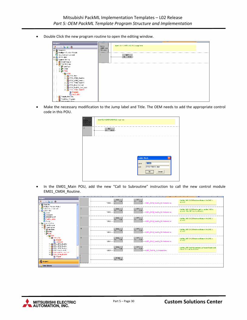
Mitsubishi PackML Implementation Templates – L02 Release Part 5: OEM PackML Template Program Structure and Implementation
Double Click the new program routine to open the editing window.
Make the necessary modification to the Jump label and Title. The OEM needs to add the appropriate control code in this POU.
In the EM01_Main POU, add the new “Call to Subroutine” instruction to call the new control module EM01_CM04_Routine.
Custom Solutions Center Custom Solutions Center Custom Solutions Center Part 5 – Page 30
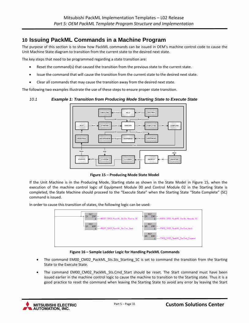
Mitsubishi PackML Implementation Templates – L02 Release Part 5: OEM PackML Template Program Structure and Implementation
10 Issuing PackML Commands in a Machine Program The purpose of this section is to show how PackML commands can be issued in OEM’s machine control code to cause the Unit Machine State diagram to transition from the current state to the desired next state.
The key steps that need to be programmed regarding a state transition are:
Reset the command(s) that caused the transition from the previous state to the current state.
Issue the command that will cause the transition from the current state to the desired next state.
Clear all commands that may cause the transition away from the desired next state.
The following two examples illustrate the use of these steps to ensure proper state transition.
10.1 Example 1: Transition from Producing Mode Starting State to Execute State
Figure 15 – Producing Mode State Model
If the Unit Machine is in the Producing Mode, Starting state as shown in the State Model in Figure 15, when the execution of the machine control logic of Equipment Module 00 and Control Module 02 in the Starting State is completed, the State Machine should proceed to the “Execute State” when the Starting State “State Complete” (SC) command is issued.
In order to cause this transition of states, the following logic can be used:
Figure 16 – Sample Ladder Logic for Handling PackML Commands
The command EM00_CM02_PackML_Sts.Sts_Starting_SC is set to command the transition from the Starting State to the Execute State.
The command EM00_CM02_PackML_Sts.Cmd_Start should be reset. The Start command must have been issued earlier in the machine control logic to cause the machine to transition to the Starting state. Thus it is a good practice to reset the command when leaving the Starting State to avoid any error by leaving the Start
Custom Solutions Center Custom Solutions Center Custom Solutions Center Part 5 – Page 31
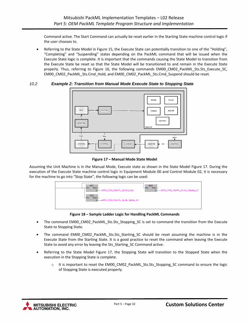
Mitsubishi PackML Implementation Templates – L02 Release Part 5: OEM PackML Template Program Structure and Implementation
Part 5 – Page 32
Command active. The Start Command can actually be reset earlier in the Starting State machine control logic if the user chooses to.
Referring to the State Model in Figure 15, the Execute State can potentially transition to one of the “Holding”, “Completing” and “Suspending” states depending on the PackML command that will be issued when the Execute State logic is complete. It is important that the commands causing the State Model to transition from the Execute State be reset so that the State Model will be transitioned to and remain in the Execute State properly. Thus, referring to Figure 16, the following commands EM00_CM02_PackML_Sts.Sts_Execute_SC, EM00_CM02_PackML_Sts.Cmd_Hold, and EM00_CM02_PackML_Sts.Cmd_Suspend should be reset.
10.2 Example 2: Transition from Manual Mode Execute State to Stopping State
Figure 17 – Manual Mode State Model
Assuming the Unit Machine is in the Manual Mode, Execute state as shown in the State Model Figure 17. During the execution of the Execute State machine control logic in Equipment Module 00 and Control Module 02, it is necessary for the machine to go into “Stop State”, the following logic can be used:
Figure 18 – Sample Ladder Logic for Handling PackML Commands
The command EM00_CM02_PackML_Sts.Sts_Stopping_SC is set to command the transition from the Execute State to Stopping State.
The command EM00_CM02_PackML_Sts.Sts_Starting_SC should be reset assuming the machine is in the Execute State from the Starting State. It is a good practice to reset the command when leaving the Execute State to avoid any error by leaving the Sts_Starting_SC Command active.
Referring to the State Model Figure 17, the Stopping State will transition to the Stopped State when the execution in the Stopping State is complete.
o It is important to reset the EM00_CM02_PackML_Sts.Sts_Stopping_SC command to ensure the logic of Stopping State is executed properly.
Custom Solutions Center Custom Solutions Center Custom Solutions Center
Custom Solutions Center
Users Guide
Low Cost OEM PackML Templates L02 Release: Part 6 – GOT Screens
Version LC-1.0
Content
1 .........................................................................................................................................................................1 Introduction
2 ...............................................................................................................1 Low Cost PackML Template System Architecture
3 .......................................................................................................................1 GOT Communication Channel Configuration
4 ....................................................................................................................................................................3 Sample Screens
4.1 ..................................................................................................................................................3 PackML Mode Screens
4.1.1. .......................................................................................................................................3 Producing Mode Screen
4.1.2. ..................................................................................................................................4 Maintenance Mode Screen
4.1.3. ...........................................................................................................................................4 Manual Mode Screen
4.2 ......................................................................................................................................................5 Timer Value Screens
4.2.1. ..................................................................................................................5 Producing Mode Timer Value Screen
4.2.2. .............................................................................................................5 Maintenance Mode Timer Value Screen
4.2.3. ......................................................................................................................6 Manual Mode Timer Value Screen
Part 6 – i Custom Solutions Center Custom Solutions Center Custom Solutions Center

Part 6 – ii Custom Solutions Center Custom Solutions Center Custom Solutions Center
Revision History
Version Revision Date Description
L02 Release V1.0 March 31, 2011 Initial release of PackML OEM Implementation Templates for L02 PLC
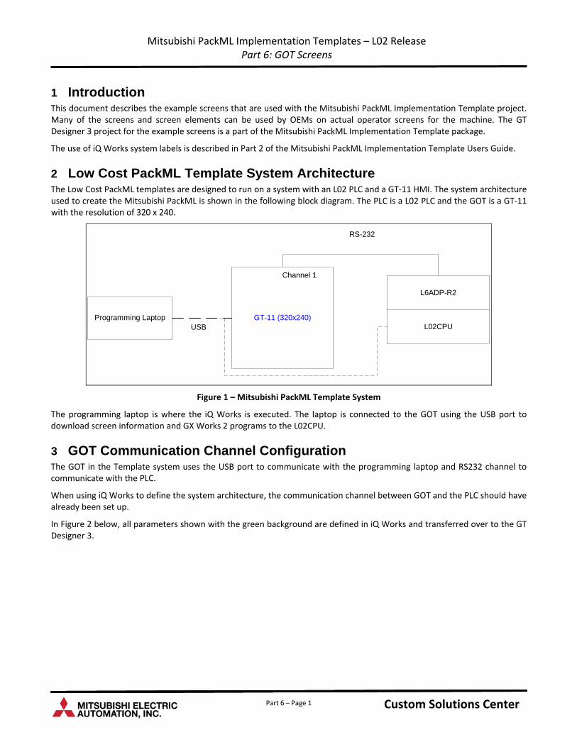
Mitsubishi PackML Implementation Templates – L02 Release Part 6: GOT Screens
1 Introduction This document describes the example screens that are used with the Mitsubishi PackML Implementation Template project. Many of the screens and screen elements can be used by OEMs on actual operator screens for the machine. The GT Designer 3 project for the example screens is a part of the Mitsubishi PackML Implementation Template package.
The use of iQ Works system labels is described in Part 2 of the Mitsubishi PackML Implementation Template Users Guide.
2 Low Cost PackML Template System Architecture The Low Cost PackML templates are designed to run on a system with an L02 PLC and a GT‐11 HMI. The system architecture used to create the Mitsubishi PackML is shown in the following block diagram. The PLC is a L02 PLC and the GOT is a GT‐11 with the resolution of 320 x 240.
Programming Laptop GT-11 (320x240)L02CPUUSB
L6ADP-R2
Channel 1
RS-232
Figure 1 – Mitsubishi PackML Template System
The programming laptop is where the iQ Works is executed. The laptop is connected to the GOT using the USB port to download screen information and GX Works 2 programs to the L02CPU.
3 GOT Communication Channel Configuration The GOT in the Template system uses the USB port to communicate with the programming laptop and RS232 channel to communicate with the PLC.
When using iQ Works to define the system architecture, the communication channel between GOT and the PLC should have already been set up.
In Figure 2 below, all parameters shown with the green background are defined in iQ Works and transferred over to the GT Designer 3.
Custom Solutions Center Custom Solutions Center Custom Solutions Center Part 6 – Page 1
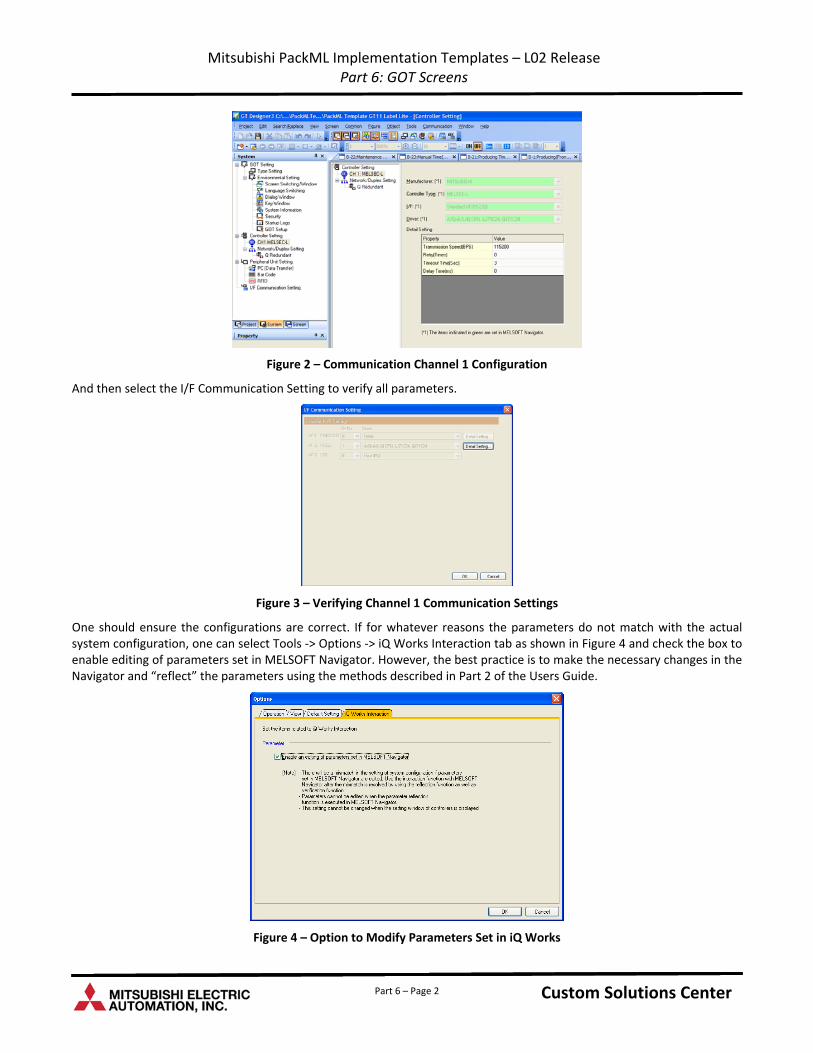
Mitsubishi PackML Implementation Templates – L02 Release Part 6: GOT Screens
Figure 2 – Communication Channel 1 Configuration
And then select the I/F Communication Setting to verify all parameters.
Figure 3 – Verifying Channel 1 Communication Settings
One should ensure the configurations are correct. If for whatever reasons the parameters do not match with the actual system configuration, one can select Tools ‐> Options ‐> iQ Works Interaction tab as shown in Figure 4 and check the box to enable editing of parameters set in MELSOFT Navigator. However, the best practice is to make the necessary changes in the Navigator and “reflect” the parameters using the methods described in Part 2 of the Users Guide.
Figure 4 – Option to Modify Parameters Set in iQ Works
Custom Solutions Center Custom Solutions Center Custom Solutions Center Part 6 – Page 2
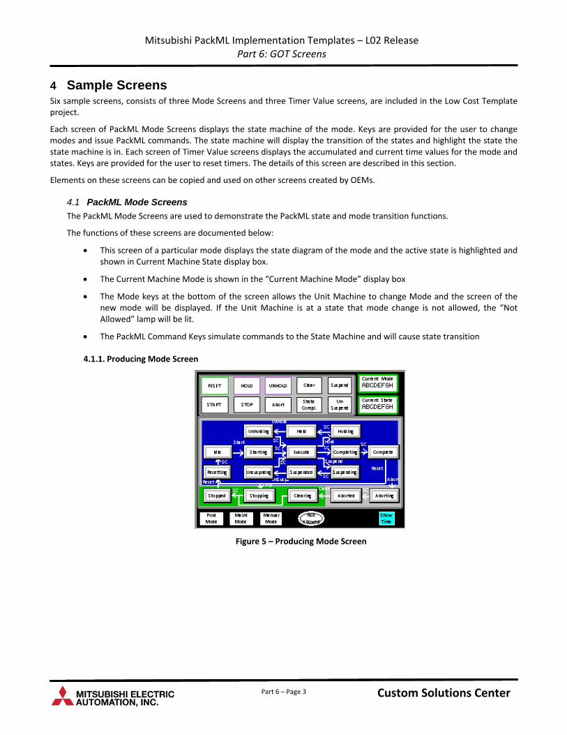
Mitsubishi PackML Implementation Templates – L02 Release Part 6: GOT Screens
4 Sample Screens Six sample screens, consists of three Mode Screens and three Timer Value screens, are included in the Low Cost Template project.
Each screen of PackML Mode Screens displays the state machine of the mode. Keys are provided for the user to change modes and issue PackML commands. The state machine will display the transition of the states and highlight the state the state machine is in. Each screen of Timer Value screens displays the accumulated and current time values for the mode and states. Keys are provided for the user to reset timers. The details of this screen are described in this section.
Elements on these screens can be copied and used on other screens created by OEMs.
4.1 PackML Mode Screens
The PackML Mode Screens are used to demonstrate the PackML state and mode transition functions.
The functions of these screens are documented below:
This screen of a particular mode displays the state diagram of the mode and the active state is highlighted and shown in Current Machine State display box.
The Current Machine Mode is shown in the “Current Machine Mode” display box
The Mode keys at the bottom of the screen allows the Unit Machine to change Mode and the screen of the new mode will be displayed. If the Unit Machine is at a state that mode change is not allowed, the “Not Allowed” lamp will be lit.
The PackML Command Keys simulate commands to the State Machine and will cause state transition
4.1.1. Producing Mode Screen
Figure 5 – Producing Mode Screen
Custom Solutions Center Custom Solutions Center Custom Solutions Center Part 6 – Page 3
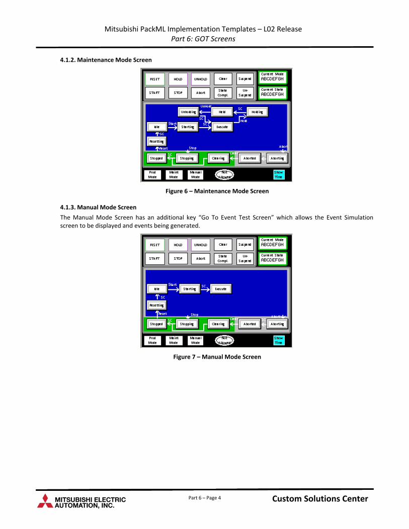
Mitsubishi PackML Implementation Templates – L02 Release Part 6: GOT Screens
4.1.2. Maintenance Mode Screen
Figure 6 – Maintenance Mode Screen
4.1.3. Manual Mode Screen
The Manual Mode Screen has an additional key “Go To Event Test Screen” which allows the Event Simulation screen to be displayed and events being generated.
Figure 7 – Manual Mode Screen
Custom Solutions Center Custom Solutions Center Custom Solutions Center Part 6 – Page 4
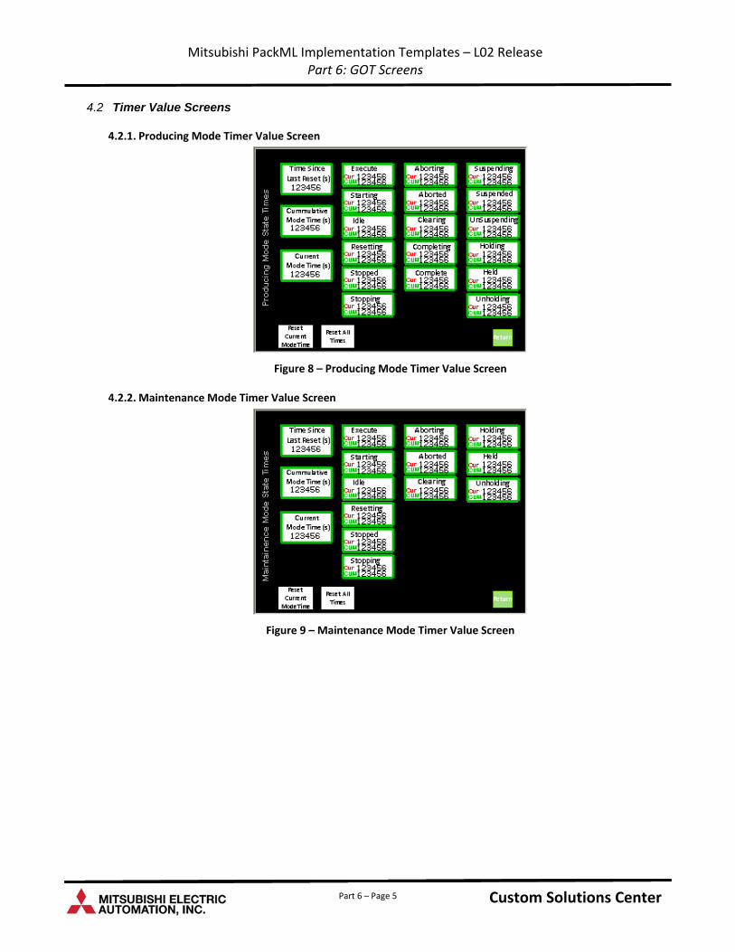
Mitsubishi PackML Implementation Templates – L02 Release Part 6: GOT Screens
4.2 Timer Value Screens
4.2.1. Producing Mode Timer Value Screen
Figure 8 – Producing Mode Timer Value Screen
4.2.2. Maintenance Mode Timer Value Screen
Figure 9 – Maintenance Mode Timer Value Screen
Custom Solutions Center Custom Solutions Center Custom Solutions Center Part 6 – Page 5
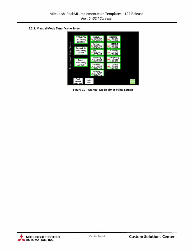
Mitsubishi PackML Implementation Templates – L02 Release Part 6: GOT Screens
Part 6 – Page 6
4.2.3. Manual Mode Timer Value Screen
Figure 10 – Manual Mode Timer Value Screen
Custom Solutions Center Custom Solutions Center Custom Solutions Center