user's guide dstar node v1 - on8jl · let's make some configuration example, assuming...
TRANSCRIPT

ON8JL DStar Node User GuideVersion 1,37
Installation:
Connector description:
1) J3 - DC power:
! 7 Vdc to 15 Vdc, 2 W maximum, positive to the center pin
2) J1 - Transmitter (for duplex mode only):
! pin1 : signal out! pin2 : ground! pin3 : PTT
3) J2 - Transceiver (simplex mode) or Receiver (duplex mode):
! pin1 : signal out! pin2 : ground! pin3 : PTT!! pin4 : signal in! pin6 : Squelch

! note: ! - if DV squelch mode is used, pin6 can be left unconnected
- node can also be used duplex mode using J2 only by connecting J1 pin 3 with J2 pin 3 together.
4) J4 - Ethernet RJ45:!! 10BaseT or 100BaseT
Setting contrast and backlight:
Apply DC power to the node.
First turn the backlight pot to set the backlight to desired level. Some level of backlight is needed for the contrast to work, so don't set backlight totally off.
Next set the contrast pot for maximum screen readability.

Setting up RX gain:
Set the RX gain pot to get 350mV rms signal on TP4 when receiving a DStar signal. It's important to perform this setting while receiving proper DStar signal, for instance transmitted by a portable transceiver nearby. Don't set it on background noise.
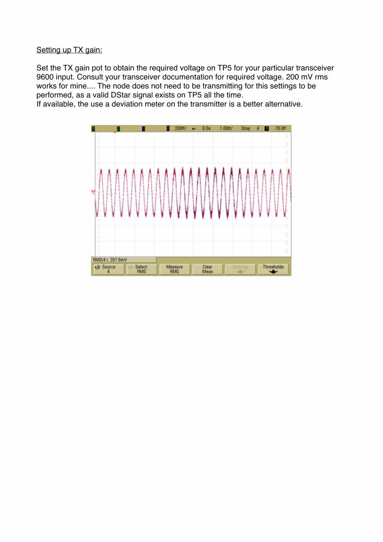
Setting up TX gain:
Set the TX gain pot to obtain the required voltage on TP5 for your particular transceiver 9600 input. Consult your transceiver documentation for required voltage. 200 mV rms works for mine.... The node does not need to be transmitting for this settings to be performed, as a valid DStar signal exists on TP5 all the time.If available, the use a deviation meter on the transmitter is a better alternative.

Connecting to ethernet network:
Cycle node DC power. By default the DHCP client is enabled and the node will initiate a negotiation with the DHCP server of your network/router to obtain a valid IP address.
During the negotiation process, the screen display following message:
Once IP address obtained, the node will display it for 5 seconds.
And go to regular operation status screen.

Setting up the internet router firewall.
The following table describe port that should be open to node's IP. In addition, if operating behind a NAT operating router, some incoming port should be redirected to the node.
For web remote monitoring/configuration:TCP 80: ! outgoing ! : open! incoming ! : open and redirected on the node
For DPlus & DExtra operation connecting as a dongle :UDP 20001:! outgoing ! : open! incoming ! : open
For DExtra operation, connecting as a repeater:UDP 30001:! outgoing ! : open! incoming ! : open and redirected on the node
For DCS operation :UDP 30051:! outgoing ! : open! incoming ! : open
For ircDDB operation:TCP 9007:! outgoing ! : open! incoming ! : openUDP 40000:! outgoing ! : open! incoming ! : open and redirected on the node
For DPRS operation:TCP 14580:! outgoing ! : open! incoming ! : open
Note: On most firewall/router with the "permit on established" option enabled as it is often the case by default, you will just have to open and redirect to the node the following ports: TCP80, UDP30001 and UDP40000.

Configuring the node:
Once connected to the network, the node adapter can be accessed from any computer running a web browser connected to the network. Point your web browser to the IP address displayed on the node startup screen.
Setting up user & password:
The very first time your log on the node adapter, the login screen is displayed to let you configure the system administrator user name and password.

Once logged on, proceed with system configuration.
Setting up the clock:
Click on the "Clock" tab and set time, date and time zone.
Enter the local time and date (not the UTC) and select your time zone. The above example is 10H22 on 28 September 2013, at a GMT +1H time zone.
You can also enter a NTP server address (IP or URL) and the node will automatically check and adjust it's clock every 10 minutes. It's important to get time, date and time zone right for ircDDB to work properly.

System configuration screen:
Next, click on the "configuration" tag and enter the relevant configuration information.Remember that most settings (at the exception of DV squelch threshold) need a "reboot" to take effect.
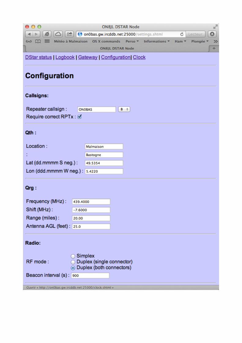


Callsigns:
Repeater callsign: The callsign of the repeater as it will be broadcasted on the air and on the DStar network. Don't use ON0BAS, but your own repeater callsign!Also select the module letter, normally A,B or C. Note that the gateway callsign will be automatically set to the repeater callsign with letter G at 8th position.
Require correct RPTx:If enabled, the node will only relay/repeat the incoming RF stream if the RPT1 settings in the radio is set to repeater's callsign. It is recommended to enable it for duplex repeater operation. This may be left uncheck if node is used as a simplex home hotspot with limited range.
Qth:
Location: The location details of the repeater. This is used by ircDDB servers to locate your repeater on the maps.
Lat & Long: The map coordinates of the repeater in decimal degrees (as they appears on aprs.fi). Those coordinates are used by both ircDDB servers and DPRS system.
Radio:
RF Mode:Choose between simplex (simple node) or duplex (repeater) operation. With "Duplex single connector" selected, you can connect the TX/RX via a single mini din cable (on J2).
Beacon interval:The time interval in seconds between node automatic self-broadcast.
Receive:
Squelch mode:In FM mode, the node will enter receive mode when J2 pin 6 is pulled down to ground, regardless of presence of proper DStar signal at the input.In DV mode, the node constantly monitor input signal for DStar signal, and if signal with a better quality than the defined threshold is detected, the node enters receive mode. This is the recommended settings.
DV Squelch level:Used only when squelch mode is set to DV. The possible value are signal quality in a scale of 0 to 1000. Set the threshold so that in absence of signal, the squelch is just closed, with the COS led just about to flicker. It's ok if the led blink randomly from time to time, every few seconds or so.
Invert Rx signal:Check if polarity of the incoming signal need polarity reversal.

Transmit:
PTT on delays:Delays in milli-seconds controlling transmitter Push To Talk operation. Default generally works. You may try to increase the value (1000 max!) when operating the node on a high latency internet connection and experimenting a lot of R2D2 on incoming gateway streams.
Invert Tx signal:Check if polarity of the outgoing signal need polarity reversal.
DPlus:
DPlus Enable:Enable the DPlus client. If disabled, no linking to DPlus reflectors/gateways will be possible.
DPlus name server IP:Enter URL or numerical IP of the DPlus name server to use. For example:ve3tnk.homelinux.net (Canada based freestar)ordstarns.dstargateway.org (US based)or188.203.83.181 (Dutch*Star NLRoot)
Authentication callsign:The callsign as registered in the DStar authentication system, typically as displayed on the personal information page of the registration system you registered with.
DExtra:
Please refer to http://xreflector.net for information on DExtra.
DExtra enable:Enable the DExtra client. If disabled, no linking to DExtra reflectors will be possible.
Connect as:Connect to DExtra reflector as a dongle or a repeater. To connect as a repeater, the node callsign should be in the xreflector local database. This is generally automatic for most xreflector is the node callsign is registered in the ircDDB system. Otherwise contact directly the xreflector sysop. On another hand, most xreflector will not accept connection as a dongle from a callsign that is known as repeater.
DCS:
Please refer to http://xreflector.net for information on DCS reflectors.
DCS enable:Enable the DCS client. If disabled, no linking to DCS reflectors will be possible.
Gateway:

Connect at power-up:If set, the node will try to link automatically at power up to the reflector/gateway listed in the below setting
Repeater callsign:The callsign of the reflector/gateway to connect at start up.
IRCDDB:
IMPORTANT: To become an ircDDB gateway, your repeater call sign need to be registered on the ircDDB system. Currently, only registered automatic station (for instance ON0xxx in Belgium) are allowed to do so. Hotspots using a OM callsign cannot act as ircDDB gateways. Please refer to http:// db0fhn.efi.fh-nuernberg.de/doku.php?id=projects:dstar:ircddb#network_policy for further information.
Enable ircDDB:When enabled, the node will operate as a full ircDDB gateway. It will also permit repeater to repeater calling and Starnet operation.Once enabled, click on update to access the next ircDDB settings.
ircDDB server IP:The URL or numerical IP of the ircDDB server to use. For europe use : group1-irc.ircddb.netFor US use : group2-irc.ircddb.net
The use of numerical IP is discouraged, as it bypass the DNS based server redundancy and workload sharing system.
ircDDB login & password:As distributed by ircDDB admin when registering your gateway.
Ethernet:
The details of the node ethernet settings. If use DHCP is set, the remaining fields are disabled, so to enter fixed IP settings, first disable DHCP, click on update and set the remaining settings.
The MAC address can also be changed manually if needed.
DPRS Interface:
enable DPRS:When enabled, the node will operate as a dprs i-gate.
DPRS server IP:The URL or numerical IP of the APRS server the node shild connect to.
Server validation code:You callsign dependent validation code. This is the same code that you use for other aprs application like ui-view for example. If you don't have one already, contact me to get it.

Posit comment:The comment text as broadcasted every 20 minutes
Remote reboot:
enable reboot via RF:When enabled, the node can be rebooted remotely with a radio. Configure the UR field of your radio to match the password.
enable daily reboot:When enabled, the node will be rebooted every day, at specified hour of the day.
Once configuration screen completed, click on "update" button for writing new settings into node non volatile memory. Alternatively, click on "reboot" button to save new settings and reboot the system. The reboot process is equivalent to cycling node power.
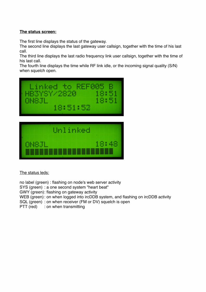
The status screen:
The first line displays the status of the gateway.The second line displays the last gateway user callsign, together with the time of his last call.The third line displays the last radio frequency link user callsign, together with the time of his last call.The fourth line displays the time while RF link idle, or the incoming signal quality (S/N) when squelch open.
The status leds:
no label (green) : flashing on node's web server activitySYS (green)! : a one second system "heart beat"GWY (green)!: flashing on gateway activityWEB (green)!: on when logged into ircDDB system, and flashing on ircDDB activitySQL (green)! : on when receiver (FM or DV) squelch is openPTT (red)! : on when transmitting

On the air!
IMPORTANT: If "Require correct RPTx" setting is enabled, the R1 field of your DStar radio MUST be properly configured with the node callsign. Otherwise the node will not relay, repeat or reply to any of the incoming RF transmission.
Let's make some configuration example, assuming the node callsign is "ON0BAS B" and that the node is linked to "REF001 C" and operating in duplex mode (repeater):
Calling CQ:
ur! : CQCQCQr1! : ON0BAS Br2! :
Local RF users and all DStar users connected directly or indirectly to REF001 C will ear your call. To call CQ locally only, first disconnect (unlink) the node from REF001 C
Calling ON3LX locally:
ur! : ON3LXr1! : ON0BAS Br2! :
Only local RF users will ear your call to ON3LX. The call is not relayed to REF001 C
Calling ON4BK on the gateway:
ur! : ON4BKr1! : ON0BAS Br2! : ON0BAS G
Local RF users and all DStar users connected directly or indirectly to REF001 C will ear your call to ON4BK

Querying the node:
If you place a short (less than 2 seconds) transmit, the node will reply with a beacon message containing the node callsign, the received signal quality (from S0 to S9) and the status of the gateway. For example:
ON0BAS B/S8 LINKED TO REF001 C
Beacon:
While idle, the node will transmit a beacon message every 5 minutes. The message contains the node call sign and the status of the gateway. For example:
ON0BAS B UNLINKED
Controlling the gateway:
You can control the gateway operation by transmitting specific commands in the UR section of your DStar radio. Remember to set R1 to the node callsign, otherwise the node will ignore your commands. All following examples assume that the node callsign is "ON0BAS B". Note that the node is not relaying your commands to the gateway so you are not disturbing the DStar user community with your local commands. However, if in duplex mode, your commands are repeated on the air so other RF listening users are aware of changes. All command are acknowledged by a beacon message describing gateway status.
Linking the gateway to a DPLus/DExtra repeater/reflector:Enter the repeater or reflector callsign you want to link to terminated by letter L (lima) in 8th position. If the callsign already have a letter in 8th position, shift this letter in 7th position. The command will fail if the gateway is already linked to another repeater/reflector. Unlink first!For example to link to "ON0CPS B":ur! : ON0CPSBLr1! : ON0BAS Br2! :
Unlinking the gateway:Enter the letter U (uniform) in the 8th position. Example:ur! : U (in the 8th position!)r1! : ON0BAS Br2! :
Querying the gateway status:Enter the letter I (india) in the 8th position. This has same effect than a short transmit (see above), at the difference that the transmit is not relayed to the gateway. Example:ur! : I (in the 8th position!)r1! : ON0BAS Br2! :

ircDDB extra features:
When enabled and configured for ircDDB operation, the following mode of operation are also available, independently and concurrently to the fact that the gateway is linked or not:
Repeater to repeater operation:You can call CQ directly on another repeater via the native ICOM G2 protocol. For example, to call a CQCQCQ on remote "ON0CPS B" repeater:ur! : /ON0CPSBr1! : ON0BAS Br2! : ON0BAS G
Callsign routing:You can call a specific OM using his callsign in UR. The ircDDB system will find instantly the last repeater he transmitted on and will relay your call on that repeater (call sign routing). The reverse is also true so you can be found the same way. Use rx>cs button on your radio to allows you to configure instantly your UR to reply back to any specific call easily. Refer to ICOM's radio documentation for details.
Starnet operation:You can join, participate to and leave any starnet group. see http://k7ve.org/blog/2011/04/starnet- digital/ for more information

Monitoring the node status via the web:
You can monitor the node operation from any computer connected to the network running a web browser. The status page refresh every two seconds.
The logbook page list all callsign heard on the RF input of the node, with date and time of the last transmission.

In addition, when ircDDB is enabled, the node ircDDB real time status and live operation can be monitored onhttp://status.ircddb.net/cgi-bin/ircddb-gw
andhttp://www.ircddb.net/live.htm

Controlling the gateway via the web:
You can also control the gateway linking/unlinking via the web by clicking on the "gateway" page.
To link the gateway to a DPlus or DExtra reflector or repeater, you can either select the reflector/repeater in the "Reflectors" drop down control, or type it directly in the "Other gateway" text field. Only type uppercase callsigns, no URL or numerical IP.The node will then find the IP of the system you typed the callsign by using DPlus name server or ircDDB, or DNS depending of what protocol is enabled and on the callsign you entered.Once IP resolved, it is stored in internal cache memory. At power up, if DPlus enabled, the cache is pre-filled with DPlus reflector list obtained from the DPlus name server.Note that the "Reflectors" drop down list reflects the cache content.
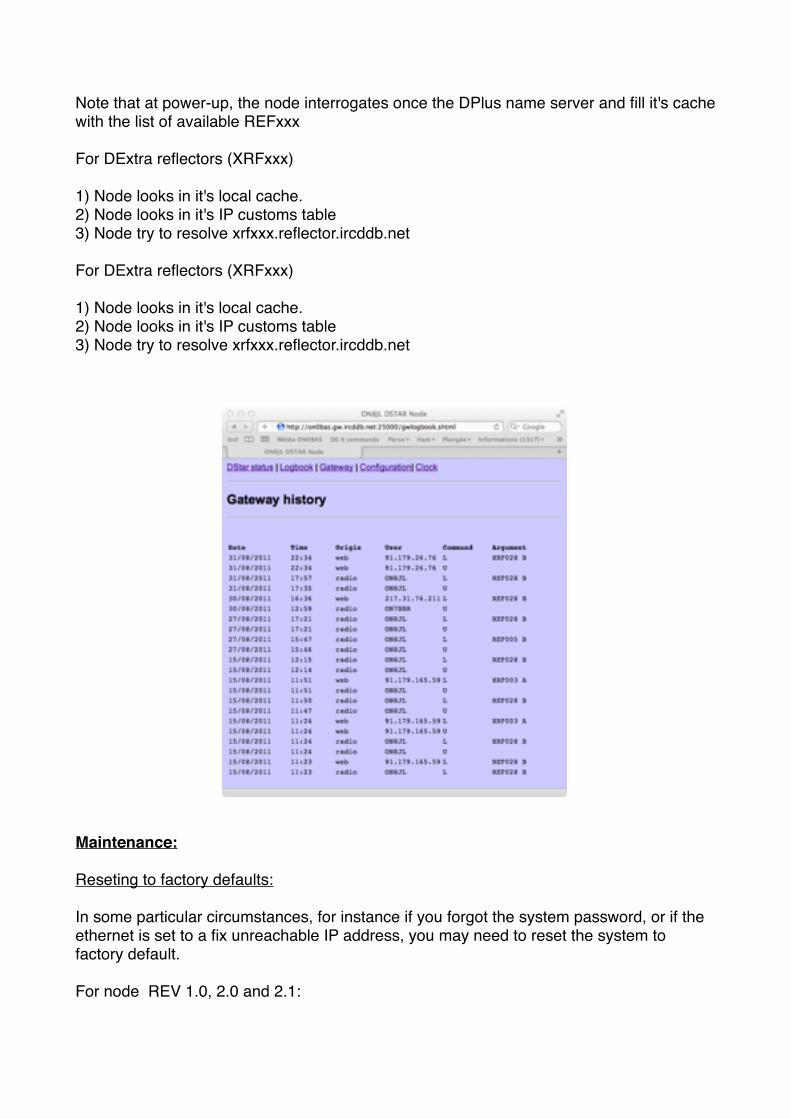
In addition, the "history" page display a chronological list all linking/unlinking operations, together with their source (RF user or Web operator)
The node keep a local copy of the IP it uses in a cache. This cache helps speeding up successive connection to the same reflector, as the IP does not need to be resolved anymore. The cache is cleared every time the node is rebooted.
The "Customs IP table" options lets you specify directly IP addresses of some reflectors.It's normally not needed, as the reflectors IP are locatable via DPlus name servers and / or DNS. The node uses the following strategies to resolve reflectors IP addresses:
For DPlus reflectors (REFxxx)
1) Node looks in it's local cache.2) Node looks in it's IP customs table3) Node interrogates the configured DPlus name server4) Node try to resolve refxxx.dstargateway.org
Note that at power-up, the node interrogates once the DPlus name server and fill it's cache with the list of available REFxxx
For DExtra reflectors (XRFxxx)
1) Node looks in it's local cache.2) Node looks in it's IP customs table3) Node try to resolve xrfxxx.reflector.ircddb.net
For DExtra reflectors (XRFxxx)
1) Node looks in it's local cache.2) Node looks in it's IP customs table3) Node try to resolve xrfxxx.reflector.ircddb.net
Maintenance:
Reseting to factory defaults:
In some particular circumstances, for instance if you forgot the system password, or if the ethernet is set to a fix unreachable IP address, you may need to reset the system to factory default.
For node REV 1.0, 2.0 and 2.1:

Power on the node with a jumper installed between pin 1 and pin 2 of the extension connector (P2).
For node REV 3.0:
Replacing the internal battery:
The CR2032 lithium battery provides power to the real time clock when system is disconnected from DC power. It should last at least one year. To replace the battery, make sure the power dc connector is removed and gently slide out the old battery. Slide in the new one. Don't use plier to grab the battery as it may short circuit the battery.

Upgrading firmware on hardware REV1.0 to 2.1:
The firmware can be upgraded via node extension connector (P2) and the provided USBto Serial cable.
Procedure:
1) connect the USB cable to the PC and the node
For the version 2.1 and lower only three wires are used for connecting the node to the terminal . The extension connector is located inside the box on the top of the PCB near the LCD . The box will be opened by removing the 4 screws .
2) if not already installed, install the FTDI drivers
3) start hyper terminal or another terminal emulator and use following settings:
baudrate: 115200 data bits: 8 stop bits: 1 parity: none handshake : none
4) power up the node
5) the node displays "FIRMWARE UPGRADE MODE" on LCD

6) the following menu appears on terminal emulator window
7) type 1
8) upload the firmware using Ymodem
9) once completed, remove cable and cycle node power

Upgrading firmware on hardware REV3.0 and above :
The firmware can be upgraded via node extension connector (P2) and the provided USBto Serial cable.
Procedure:
1) connect the USB cable to the PC and the node
For the version 3.0 the extension connector is located of the bottom of the pcb and accessed by removing the small cover on the back of the boxThe connector alignment is described on the small cover ( wiring colour, …)
2) if not already installed, install the FTDI drivers
3) start hyper terminal or another terminal emulator and use following settings:

baudrate: 115200 data bits: 8 stop bits: 1 parity: none handshake : none
4) power up the node
5) the node displays "FIRMWARE UPGRADE MODE" on LCD
6) the following menu appears on terminal emulator window
7) type 1

8) upload the firmware using Ymodem
9) once completed, remove cable and cycle node power