users guide flydat rev.1 10/1997 - rotax-owner.com · manual is not understood completely you may...
TRANSCRIPT

Modification-No. Reference OM Date Page- 0 - FLYdat 1997 10 01 - 1 -
WARNINGBefore starting the engine, read the Operator`s Manual. Failure to do so may resultin personal injuries including death .Consult the original equipment manufacturer`s handbook for additional instructions!
The manual must remain with the engine / original equipment in case of sale.
Recommended price: ATS 100,--Part no.: 897 730 DM 14,--
Flydat
U S E R ´ S G U I D EU S E R ´ S G U I D Ef o rf o r
FLYdatFLYdatFLYdatFLYdatFLYdat
Ausgabe: 0 vom 1997 10 01
These technical data and the information contained therein are property ofBOMBARDIER-ROTAX GmbH and must not be reproduced, neither in entirety norpartially, and passed on to third parties without previous consent in writing byBOMBARDIER-ROTAX GmbH. This text must be written on every complete orpartial reproduction.
Copyright - BOMBARDIER-ROTAX GmbHApproval of translation has been done by best knowledge and judgement - in any case the original text in
German language is authoritative.

Page Date OM Reference Modification-No.- 2 - 1997 10 01 FLYdat - 0 -
Blank Page

Modification-No. Reference OM Date Page- 0 - FLYdat 1997 10 01 - 3 -
1) Inhaltsverzeichnis1) Table of contents ..........................................................................3
2) Preface ...........................................................................................4
3) Warning..........................................................................................5
4) Description of design ...................................................................64.1) General data .................................................................................... 64.2) Possible configurations ................................................................. 74.3) Display allocation ........................................................................... 8
5) Technical data ............................................................................. 115.1) Warn- and alarm limits ................................................................. 13
6) Installation .................................................................................. 156.1) General information ...................................................................... 156.2) Outline dimensions of the Flydat ................................................ 156.3) Electric Connections .................................................................... 166.4) Sensor kits ..................................................................................... 166.5) Installation of the sensors ........................................................... 176.6) Installation plan for the individual sensor kits .......................... 196.7) Signalling device ........................................................................... 226.8) Wiring diagram for different engine types: ................................ 23
7) Operation .................................................................................... 277.1) Initial start-up ................................................................................ 277.2) Reaction at start ............................................................................ 277.3) Possible display ............................................................................ 297.4) Control of readings ....................................................................... 317.5) Data recording in operation ......................................................... 327.6) Report of errors ............................................................................. 337.7) Fuse of unit .................................................................................... 35
8) Service and Distribution Partners ............................................36
9) Conditions of warranty. ............................................................. 439.1) Period of warranty ........................................................................ 439.2) Tasks performed by an authorized BOMBARDIER-
ROTAX distributor ......................................................................... 439.3) Condition to have warranty work performed ............................. 439.4) Exclusion - not covered by warranty: ........................................ 449.5) Expressed or implied warranties: ............................................... 459.6) Consumer assistance procedure: ............................................... 459.7) Warranty claims ............................................................................ 469.9) Caution ........................................................................................... 46
7) Warranty registration card ........................................................ 49

Page Date OM Reference Modification-No.- 4 - 1997 10 01 FLYdat - 0 -
2) Preface
Congratulations to your decision to use the FLYdat , speciallydeveloped for ROTAX Aircraft Engines for indicating and storingof engine operation data. Prior to taking the FLYdat into service,please, read the Guide carefully, as it will aquaint you with thebasic knowledge of technical data, installation and the safehandling of the FLYdat.
If you don't understand everything in this manual or in case ofany questions arising, please, contact the nearest authorizedROTAX Distributor or Service Partner.
This manual is protected by copyright, with all rights reserved.It may not, in whole or part, be copied, reproduced, translated orconverted to any electronic medium or machine-readable formwithout prior consent in writing from ROTAX.
We wish you fun and satisfaction when flying the Rotax powered
aircraft, supplemented by the FLYdat.

Modification-No. Reference OM Date Page- 0 - FLYdat 1997 10 01 - 5 -
3) WarningThe FLYdat has not undergone any safety and durability examination to theStandards of Civil Aviation but it does incorporate the latest technicaldevelopment and has been thoroughly tested.
Despite of FLYdat being a precision instrument, false indication ormisinterpretation of data could occur. By utilizing the FLYdat the useracknowledges the possible danger and responsibility for all risks.
To minimize the risks, study the Guide carefully. Before the content of theManual is not understood completely you may not take the FLYdat intoService.
Please, pay attention to the following symbols throughout the manual empha-sizing particular information.
▲ WARNING: Identifies an instruction, which if not followed, may causeserious injury or even death.
■ ATTENTION: Denotes an instruction which if not followed, may severelydamage the engine or other components.
◆ NOTE: Information useful for better handling of the FLYdat.
P.T.O. stands for power take off side and M.S. for magneto side throughoutTechnical Documentation of Rotax, for precise destination of location.
00334 00996MS
AS
Cyl
. 4 Cyl
. 3
Cyl
. 2 Cyl
. 1

Page Date OM Reference Modification-No.- 6 - 1997 10 01 FLYdat - 0 -
4) Description of design
4.1) General data
TheFLYdat represents an instrument especially developed for Rotaxaircraft engines for indication and acquisition of engine operating datareadily accessible for the pilot.
The FLYdat is furnished with 8 sensor input ports, which can beoccupied variably according to engine type.
The operating data is permanently compared with the engine specificoperating limit. If the signalled operating data exceeds the storedoperating limit, the FLYdat will warn the pilot.
In addition all the input ports are equipped with a maximum alarm,responding when picked-up value is equal or above the stored limit.
Two or more readings will never be indicated simultaneously but insuccession updated on the display. The updating of all the readingstakes less than one second.
The FLYdat keeps the pilot informed on the following actual readings:
➪ Engine speed
➪ Cylinder head temperature (CHT)
➪ Exhaust gas temperature (EGT)
➪ Ambient air temperature (not on engines 912 / 914)
➪ Temperature of cooling water (only on engines 582 UL, 618 UL)
➪ Oil temperature and oil pressure (only on engines 912 / 914)
Besides the topical data, the FLYdat shows also the hours of operation.
The seperately picked up readings are issued in accordance to displayallocation.
For maintenance and analyses of engine shortcomings the FLYdatpicks up and stores the essential operating data. For safety's sake theprogrammed service date reminds you of the scheduled maintenanceof engine.
The handy unit offers a number of appreciable assets compared toconventional dial gauge indication. Besides easy installation, the lowweight and compact size are essential advantages of the FLYdat .

Modification-No. Reference OM Date Page- 0 - FLYdat 1997 10 01 - 7 -
4.2) Possible configurations
The FLYdat is supplied by Rotax with a standard configuration.
With the standard configuration all trigger levels for warning- and alarmsystem are set to the maximum of the measuring range , i.e. nochecks for exceeding of warning limits.
The FLYdat can be coordinated by the authorized Rotax Distributor withthe respective engine type. With this configuration warn- and alarmlimits are set for specific channels.
Configuration is available for the following engine types:
➪ 447 UL SCDI
➪ 503 UL DCDI
➪ 582 UL DCDI
➪ 618 UL DCDI
➪ 912 DCDI series
➪ 914 DCDI series
➪ STANDARD
By configuration of the FLYdat , the engine type, engine number, hoursof operation, temperature unit and the respective engine limits areprogrammed.
◆ NOTE: If the FLYdat is utilized on a used engine, the existingtime of operation can be taken into account.
▲ WARNING: If using the FLYdat with the standard configurationthe indication will work flawless, but because warning-and alarm limits are set to a high level, therefore nowarning at danger .
Page Date OM Reference Modification-No.- 8 - 1997 10 01 FLYdat - 0 -
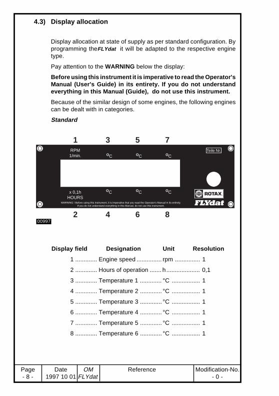
4.3) Display allocation
Display allocation at state of supply as per standard configuration. Byprogramming theFLYdat it will be adapted to the respective enginetype.
Pay attention to the WARNING below the display:
Before using this instrument it is imperative to read the Operator'sManual (User's Guide) in its entirety. If you do not understandeverything in this Manual (Guide), do not use this instrument.
Because of the similar design of some engines, the following enginescan be dealt with in categories.
Standard
RPM1/min. OC OC OC
x 0,1hHOURS
OC OC OC
WARNING ! Before using this instrument, it is imperative that you read the Operator's Manual in its entirely.If you do not understand everything in this Manual, do not use this instrument.
Teile Nr.
FLYdat
1 3 5 7
2 4 6 800997
Display field Designation Unit Resolution
1 ............. Engine speed ............... rpm ............... 1
2 ............. Hours of operation ....... h .................... 0,1
3 ............. Temperature 1 ............. °C ................. 1
4 ............. Temperature 2 ............. °C ................. 1
5 ............. Temperature 3 ............. °C ................. 1
6 ............. Temperature 4 ............. °C ................. 1
7 ............. Temperature 5 ............. °C ................. 1
8 ............. Temperature 6 ............. °C ................. 1

Modification-No. Reference OM Date Page- 0 - FLYdat 1997 10 01 - 9 -
Liquid cooled 2-stroke-engines
➪ 582 UL
➪ 618 UL
Display field Designation Unit Resolution
1 ............. Engine speed ............... rpm ............... 1
2 ............. Hours of operation ....... h .................... 0,1
3 ............. Exhaust gas temp. PTO°C or °F ........ 1 or 10
4 ............. Exhaust gas temp. MS °C or °F ........ 1 or 10
5 ............. Cylinder head temp. PTO°C or °F ...... 1
6 ............. Cylinder head temp. MS°C or °F ........ 1
7 ............. Coolant temperature .... °C or °F ........ 1
8 ............. Ambient air temperature°C or °F ........ 1
Aircooled 2-stroke-engines
➪ 447 UL
➪ 503 UL
Display coverage as above, but display 7 not occupied.
RPM1/min.
EGT/PTOOC
CHT/PTOOC
COOLANTOC
x 0,1hHOURS
OCEGT/MAG
OCCHT/MAG
OCAIR
WARNING ! Before using this instrument, it is imperative that you read the Operator's Manual in its entirely.If you do not understand everything in this Manual, do not use this instrument.
Teile Nr.
FLYdat
1 3 5 7
2 4 6 800998
RPM1/min.
EGT/PTOOC
CHT/PTOOC
x 0,1hHOURS
OCEGT/MAG
OCCHT/MAG
OCAIR
WARNING ! Before using this instrument, it is imperative that you read the Operator's Manual in its entirely.If you do not understand everything in this Manual, do not use this instrument.
Teile Nr.
FLYdat
1 3 5 7
2 4 6 800999

Page Date OM Reference Modification-No.- 10 - 1997 10 01 FLYdat - 0 -
Liquid cooled 4-stroke-engines
➪ 912 DCDI series
➪ 914 DCDI series
Display field Designation Unit Resolution
1 ............. Engine speed ............... rpm ............... 1
2 ............. Hours of operation ....... h .................... 0,1
3 ............. Exhaust gas temp. AS . °C or °F ........ 1 or 10
4 ............. Exhaust gas temp. MS °C or °F ........ 1 or 10
5 ............. Cylinder head temp. .... °C or °F ........ 1
6 ............. x)
7 ............. Oil temperature ............ °C or °F ........ 1
8 ............. Oil pressure ................. bar ................ 0,1
x) indicating the line of cylinders from which the exhaust gas temp.is picked up
◆ NOTE: Arrow ← denotes left line of cylinders
Arrow → denotes right line of cylinders
The change over of the readings of exhaust gastemperature is every 6 to 8 seconds.
RPM1/min.
EGT/PTO OC
CHTOC
OIL TEMPOC
x 0,1hHOURS
OCEGT/MAG
EGT DisplayLEFT-RIGHT
x 0,1 barOIL PRESS
WARNING ! Before using this instrument, it is imperative that you read the Operator's Manual in its entirely.If you do not understand everything in this Manual, do not use this instrument.
Teile Nr.
FLYdat
1 3 5 7
2 4 6 801000
Modification-No. Reference OM Date Page- 0 - FLYdat 1997 10 01 - 11 -
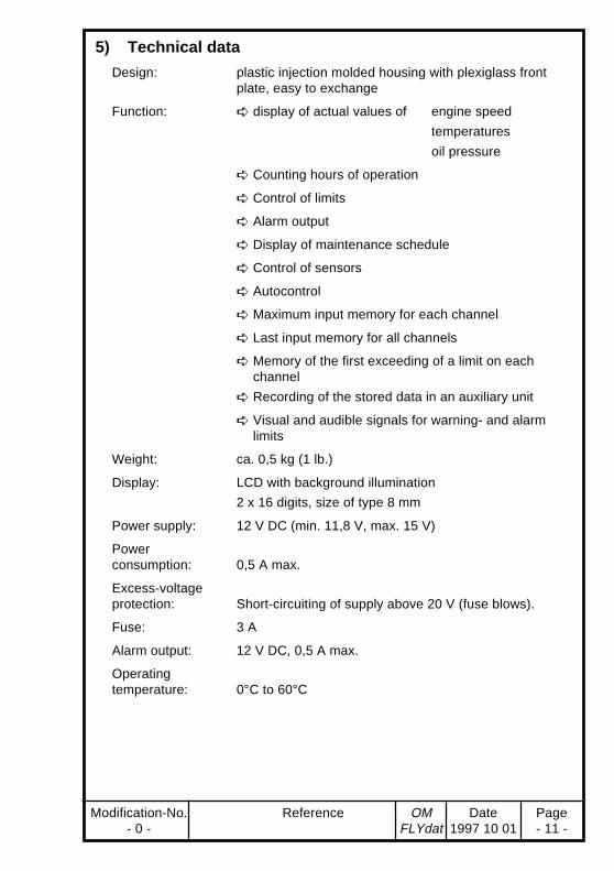
5) Technical data
Design: plastic injection molded housing with plexiglass frontplate, easy to exchange
Function: ➪ display of actual values of engine speed
temperatures
oil pressure
➪ Counting hours of operation
➪ Control of limits
➪ Alarm output
➪ Display of maintenance schedule
➪ Control of sensors
➪ Autocontrol
➪ Maximum input memory for each channel
➪ Last input memory for all channels
➪ Memory of the first exceeding of a limit on eachchannel
➪ Recording of the stored data in an auxiliary unit
➪ Visual and audible signals for warning- and alarmlimits
Weight: ca. 0,5 kg (1 lb.)
Display: LCD with background illumination
2 x 16 digits, size of type 8 mm
Power supply: 12 V DC (min. 11,8 V, max. 15 V)
Powerconsumption: 0,5 A max.
Excess-voltageprotection: Short-circuiting of supply above 20 V (fuse blows).
Fuse: 3 A
Alarm output: 12 V DC, 0,5 A max.
Operatingtemperature: 0°C to 60°C

Page Date OM Reference Modification-No.- 12 - 1997 10 01 FLYdat - 0 -
Storage temp.: -20°C to +60°C
Vibration limits: amplitude: max. 0,36 mm
acceleration: max. 5 g
frequency: 10 to 500 Hz
Shock limits: acceleration: max. 50 g
duration of shock: 11 ms
Permanent shocklimit: acceleration: max. 10 g
duration of shock: 6 ms
Sensor inputs :
4 x input for thermo couple NiCrNi (type K):
measuring range: -20°C to +999°C at 25°C terminal temperature
accuracy: ± 5°C
application: cylinder head temperature (CHT), exhaust gas tempera-ture (EGT)
2 x input resistance thermometer (PT 100):
measuring range: -20°C to +203°C
accuracy: ± 2°C
application: air-, coolant temperature (2-stroke),
oil-, cylinder head temperature (912 / 914)
1 x input oil pressure pick-up:
measuring range: 0 to 10 bar
accuracy: ± 0,2 bar
application: oil pressure (912 / 914)
1 x rpm input:
measuring range: 1030 to 9990 rpm
accuracy: ± 10 rpm
■ NOTE: For configuration on 912 / 914 one impulse per revolution,but for all other configurations 6 impulses per revolution arerequired for correct rev-counting.
hour meter:
measuring range: 0,0 to 3200 h
indicating range: 0,0 to 999,9 h (after 999,9 h change to Zero)
accuracy: ± 2 sec/h at operation without interruption

Modification-No. Reference OM Date Page- 0 - FLYdat 1997 10 01 - 13 -
5.1) Warn- and alarm limits
If the FLYdat has been configurated by a distributor, the following limitsare stored.
◆ NOTE: Please, pay attention to limits as specified in theOperator's Manual for engine.
Don't run engine above these limits.
Engine type 447 and 503 UL
Display Unit Warn limit Alarm limit
Engine speed .... (rpm) .................... 6800 .................... 7000
Exh. gas temp. .. (°C) ........................ 650 ...................... 680
Cyl. head temp. . (°C) ........................ 250 ...................... 275
Ambient air temp.(°C) ........................ 40 ........................ 50
Engine type 582 UL DCDI
Display Unit Warn limit Alarm limit
Engine speed .... (rpm) .................... 6800 .................... 7000
Exh. gas temp. .. (°C) ........................ 650 ...................... 680
Cyl. head temp. . (°C) ........................ 165 ...................... 180
Coolant temp. .... (°C) ......................... 85 ........................ 95
Ambient air temp.(°C) ........................ 40 ........................ 50
Engine type 618 UL
Display Unit Warn limit Alarm limit
Engine speed .... (rpm) .................... 7000 .................... 7300
Exh. gas temp. .. (°C) ........................ 650 ...................... 680
Cyl. head temp. . (°C) ........................ 165 ...................... 180
Coolant temp. .... (°C) ......................... 85 ........................ 95
Ambient air temp.(°C) ........................ 40 ........................ 50

Page Date OM Reference Modification-No.- 14 - 1997 10 01 FLYdat - 0 -
Engine type 912
Display Unit Warn limit Alarm limit
Engine speed .... (rpm) .................... 5800 .................... 6000
Exh. gas temp. .. (°C) ........................ 880 ...................... 900
Cyl. head temp. . (°C) ........................ 150 ...................... 160
Oil temperature. (°C) ........................ 140 ...................... 150
Oil pressure max.(°C) ....................... 6,0 ....................... 8,0
Oil pressure min. (bar) .................... 2,0 ....................... 1,0
Engine type 914
Display Unit Warn limit Alarm limit
Engine speed ..... (rpm) ................... 5800 .................... 6000
Exh. gas temp. ... (°C) ...................... 950 ..................... 1000
Cyl. head temp. .. (°C) ...................... 135 ...................... 150
Oil temperature .. (°C) ...................... 130 ...................... 145
Oil pressure max.(bar) ...................... 6,0 ....................... 8,0
Oil pressure min. (bar) ..................... 2,0 ....................... 1,0

Modification-No. Reference OM Date Page- 0 - FLYdat 1997 10 01 - 15 -
6) Installation
6.1) General information
Prior to the installation of the FLYdat look for a suitable location in thecockpit, taking into consideration the following:
➪ protection against too high temperatures
◆ NOTE: The unit operates flawless up to the max. operatingtemperature of 60°C.
➪ protection against excessive vibrations and shock loads (seeTechnical Data for permissible values). For certain conditions itmight be necessary for keeping within specifications, to installthe unit vibration damped.
➪ Protection against dampness and any kind of gasoline and oilwetting.
➪ Ensure clear and distinct visibility, direct and without glare
➪ Easy maintenance
In consideration of reliability and durability try to meet all theseconditions.
6.2) Outline dimensions of the Flydat
Flydat
01001
1
◆ NOTE: Attachment screws for the FLYdat are not in thesupply scope.

Page Date OM Reference Modification-No.- 16 - 1997 10 01 FLYdat - 0 -
6.3) Electric Connections
The plug receptacles with interlocking, for connection of the sensorsand power supply are located on the backside. For the wiring of sensorsand terminals consult the wiring diagram.
The fitted socket ➊ is used to program (datatransfer) the FLYdat for thedifferent engine types.
This programming is performed exclusively by the Bombardier-Rotaxdistributor. Therefore, the socket ➊ is of no significance for the user.
■ ATTENTION: Manipulation on this terminal ➊ or to plug-in anyconnection whatsoever, is not allowed.
6.4) Sensor kits
3 different sensor kits, especially assembled for each engine type areoffered from Bombardier-Rotax.
Version LC (liquid cooled 2-stroke engines)
Version AC (aircooled 2-stroke engines)
➪ 2 sensors for exhaust gas temperature (EGT)
➪ 2 spark plug seat sensors for cylinder head temperature (CHT)
➪ 2 temperature pick-ups for air and coolant temperature
(version AC with 1 air temperature sensor only)
➪ 2 sealing rings for EGT sensors
➪ 2 support angles for CHT sensors
➪ 2 cable straps
➪ 1 front plate alternatively with temperature display in °C of °F
➪ 1 sticker with wiring diagram
Version 912 / 914
➪ 4 sensors for exhaust gas temperature (EGT)
➪ 2 temperature pick-ups, for cylinder head and oil temperature
➪ 1 pick-up for oil pressure
➪ 4 sealing rings for EGT sensors
➪ 4 welding collars M8x1 for EGT sensors
➪ 1 front plate, alternatively with temperature display in °C or °F
➪ 1 sticker with wiring diagram

Modification-No. Reference OM Date Page- 0 - FLYdat 1997 10 01 - 17 -
6.5) Installation of the sensors
At installation of the sensors take into consideration the following:
➪ Route sensor lines to be protected against excessive temperatures.
➪ Route sensor lines free of vibrations, but with some flexibility.
➪ Sensor lines to be without kinks and must not chafe.
➪ The threads of the EGT sensors and pick-up of coolant have to begreased with Loctite ANTI-SEIZE, to ensure troublefree removal.
(see tightenig torque chart).
Shortcomings in these points can result in false readings, interruptionof lines or the ruin of pick-up lines and sensors.
◆ NOTE: The sensors are furnished by the supplier with pick-up lines of 2 m (6' - 6") length, but can be extendedto a max. length of 4 m (13').
Thermocouples NiCrNi (type K) to be extended with NiCrNi resistorcables only. Connections have to be soldered and insulated, preferablyby shrink tube.
Never establish connections by clamping, danger of false reading dueto higher contact resistance. NiCrNi resistor cables are available in aspecialist store or from your local Bombardier-Rotax dealer.
All other sensors can be extended by suitable stranded copper wire.
■ ATTENTION: Always bear in mind, you are dealing with measuringdevices when you install sensors, and handle thesesensitive components carefully.For any question, please contact your localBombardier-Rotax distributor.

Page Date OM Reference Modification-No.- 18 - 1997 10 01 FLYdat - 0 -
Tightening torques:
EGT- sensor ............................. 20Nm 177in.lb. + LOCTITE Anti Seize
oil pressure pick-up .................. 15Nm 133in.lb. + LOCTITE 603
CHT- sensor (912 / 914) .......... 15Nm 133in.lb. + LOCTITE 221
oil temp.- sensor (912 / 914) .... 15Nm 133in.lb. + LOCTITE 603
coolant temp.- sensor .............. 6Nm 53in.lb. + LOCTITE Anti Seize
air temp.- sensor ...................... 6Nm 53in.lb. + LOCTITE 221
■ ATTENTION: All components, liable to come off during operation,have to be secured against loss !
01004
0100701005
01002
EGT Sensor
CHT Sensor
air-,coolant-Sensor
CHT- Sensor (912 / 914)
oil temp.-Sensor (912 / 914)
oil pressure pick-up

Modification-No. Reference OM Date Page- 0 - FLYdat 1997 10 01 - 19 -
6.6) Installation plan for the individual sensor kits
liquid cooled 2-stroke engines
(Illustration shows engine type 582 UL)
01008
1) Sensor at spark plug seat (CHT)
2) Air- and liquid temperature sensor
3) EGT-sensor
4) Sealing ring

Page Date OM Reference Modification-No.- 20 - 1997 10 01 FLYdat - 0 -
Aircooled 2-stroke engines
(Illustration shows engine type 503 UL)
01009
1) Sensor at spark plug seat (CHT)
2) Air temperature sensor
3) EGT sensor
4) Sealing ring
◆ NOTE: For engine type 447 UL, 503 UL, 582 UL and 618 UL,exhaust manifolds specially prepared for installationof EGT sensors, are readily available.

Modification-No. Reference OM Date Page- 0 - FLYdat 1997 10 01 - 21 -
912 / 914
01010
01011
01012
Cylinder 3
1) oil pressure pick-up
2) oil temperature sensor
3) CHT sensor
Location of the EGT sensors:
The sensors have to be installed in the exhaust manifold ata distance of 100 mm (4") from the exhaust valve.
Welding collars are included in the sensor kit.
321

Page Date OM Reference Modification-No.- 22 - 1997 10 01 FLYdat - 0 -
6.7) Signalling device
TheFLYdat is furnished with an alarm output, which acts as the positive(+) terminal of 12V output.
◆ NOTE: A short-circuit on this output will blow the fuse of theunit.
If need be, a lamp and/or some signalling device, acoustic or visual,may be connected.
■ ATTENTION: The maximum load must not exceed 0,5 A.
At installation, the same considerations as for the Flydat unit should betaken!
Modification-No. Reference OM Date Page- 0 - FLYdat 1997 10 01 - 23 -
+-
+-
+-
+-
white
green
white
green
white
green
white
green
white
red
white
red
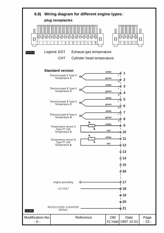
Thermocouple 1 Type KTemperature 1
Temperature sensor 2Type PT 100
Temperature 6
Thermocouple 2 Type KTemperature 2
Thermocouple 3 Type KTemperature 3
Thermocouple 4 Type KTemperature 4
Temperature sensor 1Type PT 100
Temperature 5
engine grounding
+12 VOLT
REVOLUTION- COUNTERSIGNAL
1
2
3
4
5
6
7
8
9
10
11
12
13
14
15
116
17
18
19
20
21
01014
01081
6.8) Wiring diagram for different engine types:
plug receptacles
Legend: EGT Exhaust gas temperature
CHT Cylinder head temperature
Standard version

Page Date OM Reference Modification-No.- 24 - 1997 10 01 FLYdat - 0 -
+-
+-
+-
+-
white
green
white
green
white
green
white
green
white
red
white
red
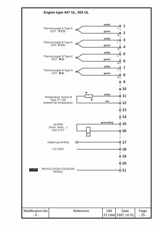
Thermocouple 1 Type KEGT P.T.O.
Temperature sensor 2Type PT 100
ambient air temperature
Thermocouple 2 Type KCHT P.T.O.
Thermocouple 3 Type KEGT M.S.
Thermocouple 4 Type KCHT M.S.
Temperature sensor 1Type PT 100
coolant temperature
groundingALARM
(Horn,lamp....)max 0,5 A
engine grounding
+12 VOLT
REVOLUTION-COUNTERSIGNAL
1
2
3
4
5
6
7
8
9
10
11
12
13
14
15
116
17
18
19
20
21
01082
Engine type 582 UL, 618 UL
Modification-No. Reference OM Date Page- 0 - FLYdat 1997 10 01 - 25 -
+-
+-
+-
+-
ALARM(Horn, lamp....)
max 0,5 A
engine grounding
+12 VOLT
REVOLUTION-COUNTERSIGNAL
white
green
white
green
white
green
white
green
white
red
grounding
Thermocouple 1 Type KEGT P.T.O.
Temperature sensor 2Type PT 100
ambient air temperature
Thermocouple 2 Type KCHT P.T.O.
Thermocouple 3 Type KEGT M.S.
Thermocouple 4 Type KCHT M.S.
1
2
3
4
5
6
7
8
9
10
11
12
13
14
15
116
17
18
19
20
2101083
Engine type 447 UL, 503 UL

Page Date OM Reference Modification-No.- 26 - 1997 10 01 FLYdat - 0 -
Engine type 912 / 914
green
white
green
white
green
white
red
white
red
white
red
grounding
white
green
ALARM(Horn, lamp....)
max 0,5 A
engine grounding
+12 VOLT
rev-counter pick-up
+-
+-
+-
+-
white
Thermocouple 3 Type KEGT
M.S. - right
Thermocouple 4 Type KEGT
M.S. - left
Temperature sensor 1Type PT 100
oil temperature
Temperature sensor 2Type PT 100
CHT
sensoroil pressure
Thermocouple 1 Type KEGT
P.T.O. - right
Thermocouple 2 Type KEGT
P.T.O. - left
1
2
3
4
5
6
7
8
9
10
11
12
13
14
15
116
17
18
19
20
21
01084
◆ NOTE: Included in the sensor kit are stickers with therelevant wiring diagram. The sticker may be glued tothe Flydat case, to facilitate the connecting of theparticular sensors.

Modification-No. Reference OM Date Page- 0 - FLYdat 1997 10 01 - 27 -
7) Operation
7.1) Initial start-up
Prior of putting the FLYdat into operation make sure that all the sensorlines and the supply cable are connected correctly.
Consult wiring diagram and the chapter electric connections for theparticular engines.
Not until all the connections are checked, supply the FLYdat withvoltage.
■ ATTENTION: The wrong polarity of the supply will blow the fuse.
With adequate voltage and correctly connected supply, the
➪ background illumination must glow, and
➪ readings are indicated on the FLYdat .
If the particular sensor lines are not connected properly the FLYdat willshow false or blinking readings.
If the FLYdat won't operate flawless, follow up tips regarding supply,faulty sensor lines and various error indications.
7.2) Reaction at start
After connecting the unit on power it will perform an autotest. With noerrors detected, the version of software applied and the programmedtemperature unit (°C or °F) will be indicated.
The display might read as follows:
„V1.22 °C“ or V1.22 °F“
NOTE: This message will remain for 6 sec. on the display.
Afterwards call for a maintenance, possibly due, might appear for 30sec., triggered by exceeding the period of operation or a limit. Withother words, if one or more limits have been exceeded or the TBOspecified is shorter than operation time since the last TBO service, thenthe maintenance request will appear.

Page Date OM Reference Modification-No.- 28 - 1997 10 01 FLYdat - 0 -
The call for maintenance appears as follows:
„Service!“
◆ NOTE: But no indication for which engine type the FLYdatwas programmed will appear on the display.
All the messages appear in 8 digits on the top line and are in Englishonly.
After the various messages, the alarm output will be activated for 1 sec.And finally, theFLYdat starts the reading operation with the actualvalues appearing on the display.

Modification-No. Reference OM Date Page- 0 - FLYdat 1997 10 01 - 29 -
■ ATTENTION: If the call for "Service " appears after switching on theunit, contact the next Bombardier-Rotax dealer with-out delay. He will find out the reason for the mainte-nance request.
7.3) Possible display
Indication of engine speed
The r.p.m. reading is in 4 digits and appears from 1030 r.p.m. onwardson the display. Recording of the speed down to 768 r.p.m. ending withlast input memory.
◆ NOTE: I.e. even with 0000 on the display (actual speed1030÷ 768 r.p.m.) a storage allocation is feasiblewith 0000 in the last input memory.
Indication of operating time
The number of operating hours is 4 digits with the resolution of 0,1 houron the display.
As only 4 digits are at disposal, time of operation is indicated up to 999,9hours followed by starting at 0,0 hours again.
The recording of the time of operation is at engine speed down to 768r.p.m. on the condition of a previous engine speed above 1030 r.p.m.
◆ NOTE: The FLYdat is capable to pick-up operating periodsup to 3276,7 h at correct overflow registration andcan record a total running time of up to 9999,9 hours.
Time between overhaul must not be longer than 3000h, leaving a safety margin of 276,7 hours.

Page Date OM Reference Modification-No.- 30 - 1997 10 01 FLYdat - 0 -
Temperature indication (Exhaust gas-, cylinder head-, oil- and airtemperature)
The temperature display is in 3 digits with a resolution to 1°C or 1°F or10°F.
◆ NOTE: As stated previously at configuration, the temperatureindication is either in °C or in °F. As only 3 digits areat disposal, the indication of the exhaust gas tem-perature in °F shows only 1/10 of its actual value onthe display, i.e. indication °F x 10 = actual exhaustgas temperature in °F.
On engine type 912/914 the indication of the exhaust gas temperatureis alternatively from one line of cylinders to the other cylinder line (seedisplay allocation). But the control of the limits is for all 4 EGT'ssimultaniously.
Indication of oil pressure (on engine 912 / 914 only)
Display of the oil pressure in 3 digits with a resolution of 0,1 bar. Theoil pressure gauge is furnished besides the generally fitted max. limitcontrol, additionally with a minimum pressure control.
The control of the minimum oil pressure is linked to the circuit 5 sec.after (for physical reasons) reaching an engine speed of at least 1030r.p.m.
Control of the max. oil pressure without time-delay.
◆ NOTE: If during the period of storing, the limits of both, themax. and min. oil pressure are exceeded, only thevalue of the oil pressure minimum is stored in thememory of 1st exceeding of limit, as only one memorycell is at disposal.

Modification-No. Reference OM Date Page- 0 - FLYdat 1997 10 01 - 31 -
7.4) Control of readings
The FLYdat can be programmed by the authorized dealer for differentwarn- and alarm limits, depending on engine type.
Distinguish between three ranges of readings control:
➪ green range (standard operation).
All readings are below or above (min. oil pressure) the warn limitsprogrammed.
➪ yellow range (exceeding of warn limits)
If one or more readings exceed the programmed warn limit, then thereading appears flashing on the display, and simultaniously thealarm output is periodically (0,25 sec.) switched on and off, until noreading exceeds warn limit.
➪ red range (exceeding of alarm limits)
If one or more readings exceed the programmed alarm limit, thenthe readings appear flashing on the display and simultaniously thealarm output is permanently activated until no reading exceeds thewarn limit.
■ WARNING: Disregard of the warn- and alarm signals might resultin injuries or endanger the life of operator or thirdparty.
◆ NOTE: The reading operation of the FLYdat remains active,even when exceeding limits, as long as it is suppliedwith the required voltage.
The control of limits responds if picked-up readingsare on or above or below (oil pressure) the pro-grammed limits.

Page Date OM Reference Modification-No.- 32 - 1997 10 01 FLYdat - 0 -
7.5) Data recording in operation
Maximum input memory
The FLYdat stores the highest reading of each channel.
Last input memory
TheFLYdat forms from each sort of readings (from max. 8 channels)the maximum, and with each 0,1 h (6 min) step of the hour-counter themaximum is stored in a ring-type puffer. At an engine stop the maximumvalues are stored too and marked for identification.
With this identification mark you can distinguish between regular 6minutes intervals and engine stop.
Criteria for identification of an engine stop:
➪ Engine speed below 768 r.p.m.
➪ Breakdown of voltage supply
The size of the ring-type puffer caters for the storage of 20 maximuminput records on 8 channel each, plus time of operation.
Memory of the first exceeding of a limit
In case of exceeding an alarm limit, the reading and time of operationto go with, is stored of each channel, but at the first time of exceedingonly.
◆ NOTE: The sorting and printing of memory contents is pos-sibly only by RDAT and CADAT.

Modification-No. Reference OM Date Page- 0 - FLYdat 1997 10 01 - 33 -
7.6) Report of errors
EEProm Test
At start of operation of the FLYdat , the data composition of theintegrated EE-Prom is checked first. If the check proves negative, theerror will be indicated on the display for c. 30 sec.
"E2 Error "
Then the FLYdat is not in working order and has to be newly programmedat a service place. The successive display of temperature unit (°C of °F)is of no significance in this case.
◆ NOTE: With the EE-Prom faulty, a service request mightfollow.
Call for Service
In the following cases a call for engine maintenance will appear on thedisplay:
➪ one or more alarm limits have been exceeded,
➪ the reading on the meter of the operating hours has surpassed theprogrammed TBO.
The maintenance message reads as follows:
"Service!"
This message will be on the display for c. 30 sec.. An engine mainte-nance has to be carried out at a service place.
Page Date OM Reference Modification-No.- 34 - 1997 10 01 FLYdat - 0 -
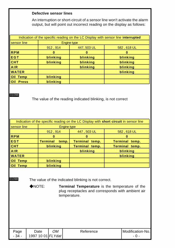
The value of the indicated blinking is not correct.
◆ NOTE: Terminal Temperature is the temperature of theplug receptacles and corresponds with ambient airtemperature.
Defective sensor lines
An interruption or short-circuit of a sensor line won't activate the alarmoutput, but will point out incorrect reading on the display as follows:
01098
01098
The value of the reading indicated blinking, is not correct
Indication of the specific reading on the LC Display with sensor line interrupted
sensor line Engine type912 , 914 447, 503 UL 582 , 618 UL
RPM 0 0 0E G T blinking blinking blinkingCHT blinking blinking blinkingA I R blinking blinkingWATER blinkingOil Temp blinkingOil Press blinking
Indication of the specific reading on the LC Display with short circuit in sensor line
sensor line Engine type912 , 914 447 , 503 UL 582 , 618 UL
RPM 0 0 0E G T Terminal temp. Terminal temp. Terminal t emp.CHT blinking Terminal temp. Terminal t emp.A I R blinking blinkingWATER blinkingOil Temp blinkingOil Temp blinking

Modification-No. Reference OM Date Page- 0 - FLYdat 1997 10 01 - 35 -
◆ NOTE: Definite defects of sensors won't activate mainte-nance request.
An intermittent sensor defect can lead to falsifiedreadings, exceeding of warn- and alarm limits, acti-vating of alarm output and triggering of maintenancerequest.
7.7) Fuse of unit
Type of fuse : Automotive, 3 A current rating (violet identificationcolour). The fuse is located on the backside of FLYdat .
The fuse fitted can blow with the:
➪ Supply voltage too high
➪ Wrong polarity of supply voltage
➪ Current at alarm output in excess of 500 mA
Easy renewal of a blown fuse by withdrawal and exchange.
■ WARNING: At exchange, use only fuse of same size and currentrating.

Page Date OM Reference Modification-No.- 36 - 1997 10 01 FLYdat - 0 -
8) Service and Distribution Partners➤Authorized DISTRIBUTORS and SERVICE CENTERS
for ROTAX Aircraft engines Edition: 1997 01 01
1 ) E U R O P E1 ) E U R O P E1 ) E U R O P EAUSTRIA:
➤ HB - FLUGTECHNIK GES.M.B.H.Dr. Adolf Schärf Str. 44A-4053 HAIDTel.: 07229 / 79104/79117, Fax: 07229 / 7910415Contact person: Ing. Heino Brditschka
BULGARIA:➤ GERGANOV - AIRCRAFT EINGINES
LTD.25B-Post 20, 23 peh. Shlp. polk Blvd.BG-6100 KAZANLAKTel.: 431 / 27 247, Fax: 431 / 23 777Contact person: Radosslav D. Gerganov
CROATIA / former YUGOSLAVIA(except SLOVENIA):
➤ SHAFT D.O.O.B.L. Mandica 161 aHR-54000 OSIJEKTel. + Fax: 054 / 760 - 046Contact person: Ing. Ivan Vdovjak
CZECHIA:➤ I.F.M. GRAMPELHUBER
Skroupova 9CS-50197 HRADEC KRALOVETel.: 049 / 56 30 127, Fax: 049 / 56 30 226Contact persons: Ing. Samal / Ing. Halek
DENMARK / THE NETHER-LANDS:
➤ FLIGHT-CENTERFlugplatzD-27777 GANDERKESEE, GERMANYTel.: 04222 / 3789, Fax: 04222 / 6042Contact person: Robert Heilig
SERVICE-CENTER of FLIGHT-CENTER in the NETHERLANDS:
DRIESSEN SCHOOL OFSKYRIDERSArendvej 13, Luchthaven LelystadNL-8218 PE LELYSTADTel.: 3202 / 88 601, Fax: 3202 / 88 714Contact person: Eddy Driessen
SERVICE-CENTER OF FLIGHT-CENTER IN DENMARK:
DANSK MICROFLY SERVICESozzivaenget 8DK-2680 SOLRODTel. + Fax: 53 14 30 60Contact person: Hans P. B. Larsen
FINLAND / NORWAY/ SWEDEN/ESTONIA/ LATVIA / LITHUANIA
BOMBARDIER NORTRAC LTD.Box 8039, FIN-96101 ROVANIEMITel.: 16 320 8111; FAX: 16 320 8200E-mail: [email protected] person: Kari Sorjonen
FRANCE / BELGIUM / MONACO /LUXEMBURG:
➤ AVIREXAérodrome de DreuxF-28500 VERNOUILLETTel.: 02 37 42 30 09, Fax: 02 37 46 26 86Contact person: Philippe Gueguen
SERVICE-CENTERS of AVIREX inFRANCE:for zone 01-02-03-04:
AVIREX SHOPAerodrome de DreuxF-28500 VERNOUILLETTel.: 02 37 42 30 09, Fax: 02 37 46 26 86Contact person: Thierry Fontaine
for zone 05:
DELTA AQUITAINE DIFFUSIONBase Saint ExupéryF-47360 MONPEZAT D’AGENAISTel.: 05 53 08 81, Fax: 05 53 95 01 02Contact person: Philippe Bouchera
SERVICE-CENTER of AVIREX forBELGIUM and LUXEMBURG:
AVIREXAérodrome de DreuxF-28500 VERNOUILLETTel.: 02 37 42 30 09, Fax: 02 37 46 26 86Contact person: Philippe Gueguen

Modification-No. Reference OM Date Page- 0 - FLYdat 1997 10 01 - 37 -
GERMANY:for postcodes 0-5-6-7-8-9:
➤ FRANZ AIRCRAFT ENGINESVERTRIEB GMBHAm Eckfeld 6e, D-83543 ROTT AM INNTel.: 08039 / 9035-0, Fax: 08039 / 9035-35Contact person: Eduard Franz
for postcodes 1-2-3-4:
➤ FLIGHT-CENTERFlugplatzD-27777 GANDERKESEETel.: 04222 / 3789, Fax: 04222 / 6042Contact person: Robert Heilig
GREAT BRITAIN / IRELAND /ICELAND:
➤ SKYDRIVE LTD.Burnside, Deppers BridgeLEAMINGTON Spa. CV 33 OSUTel.: 1926 / 612 188, Fax: 1926 / 613 781E-mail: [email protected] person: Nigel Beale
GREECE / CYPRUS:➤ KINISI
Ellis 1 str. , GR-14563 KIFISSIATel.: 01 / 620 8611; Fax: 01/ 625 0026Contact person: Michael Poulikakos
Nick Siganos
HUNGARY:➤ HALLEY
Baktai út 45, P.O. Box 425H-3300 EGERTel.: 36 / 313-830, Fax: 36 / 320-208
ITALY / MALTA:➤ ICARO MOTORI S.R.L.
Via Emilia, 61/BI-27050 REDAVALLE (PV)Tel.: 0385 / 74 591, Fax: 0385 / 74 592Contact person: Corrado Gavazzoni
SERVICE-CENTERS of ICARO :
CALVI FRANCESCOVia Trieste No. 35I-27010 SAN GENESIO (PV)Tel.: 0330 / 519894
SERGIO CHIAVEGATOVia S. Gabriele No. 30I-37063 ISOLA DELLA SCALA (VR)Tel.: + Fax: 045 / 6649013
C.U.P. CENTRO ULTRALEGGERIPARTENOPEODI FABRIZIO PISANIVia Duca d’Aosta No. 65, I-80026 CASORIA(NA)Tel. 081 / 540 3184 - 0330 / 876096Fax: 081 / 425 125
EUROFLY SRLVia Ca’ Onorai No. 50I-35015 GALLIERA VENETA (PD)Tel. + Fax: 049 / 5965464
FERRARI ULM DI FERRARI GIANNIVia Garibaldi No. 110I-35040 CASTELBALDO (PD)Tel.: 0425 / 57316, Fax: 0425 / 546422
MICROFLIGHTVia Santi No. 8I-43031 BAGANZOLA (PR)Tel. + Fax: 0521 / 601414
MOTODELTAVia Abruzzi No. 13/BI-27029 VIGEVANO (PV)Tel. + Fax: 0381 / 345465
PIANO FEDERICOCampo di Volo Località San GiacomoI-09010 SILIQUA (CA)Tel.: 0781 / 781000
POLARIS MOTOR SRLFr. ValdichiascioI-06024 GUBBIO (PG)Tel.: 075 / 920034, Fax: 075 / 920029
TRI FLY DI TRICERRI FRANCESCOVia F. Bena No. 14I-13044 CRESCENTINO (VC)Tel.: 0161 / 841 057, Fax: 0161 / 920 029
POLAND:➤ FASTON LTD.
ul. Szeroka 2PL-05-860 PLOCHOCINTel.: + Fax: 22 / 40 01 96Contact person: Wojtek Madry,Manager
ROMANIA:➤ S.C. BERIMPEX S.R.L.
Str. Dr. Taranu Grigore No. 8, Ap. 1, Sector 5R-76241 BUCHARESTTel.: 1-210 49 83; Fax: 1-312 56 48Contact person: Dr. Christian Berar
SLOVAKIA:➤ I.F.M. GRAMPELHUBER
Skroupova 9CS-50197 HRADEC KRALOVETel.: 049 / 56 30 127, Fax: 049 / 56 30 226Contact persons: Ing. Samal / Ing. Halek
SLOVENIA:➤ PIPISTREL d.o.o.
Strancarjeva Ul. 115270 AJDOVSCINATel. 065 63 873, Fax: 065 61 263E-mail: [email protected] person: Ivo Boscarol

Page Date OM Reference Modification-No.- 38 - 1997 10 01 FLYdat - 0 -
SPAIN / PORTUGAL:➤ AVIASPORT S.A.
Almazara 11E-28760 TRES CANTOS (MADRID)Tel.: (1) 803 77 11, Fax: (1) 803 55 22E-mail: [email protected] person: Mariano de Castro
SWITZERLAND / LIECHTEN-STEIN:
➤ FRANZ AIRCRAFT ENGINESVERTRIEB GMBHAm Eckfeld 6e, D-83543 Rott am Inn, GER-MANYTel.: 08039 / 9035-0, Fax: 08039 / 9035-35Contact person: Eduard Franz
SERVICE-CENTER OF FRANZ AIR-CRAFT ENGINES VERTRIEB GMBHFOR SWITZERLAND ANDLIECHTENSTEIN:
FLIEGERSCHULE BIRRFELD AGFlugplatz, CH-5242 BIRR-LUPFIGTel.+ Fax: 056/4448847
TURKEY:➤ KLASIK HALI A.S.
Cumhuriyet Mey. 9/B35210 Heykel, IZMIRTel.: (232) 376 87 70, Fax: (232) 328 02 54Contact person: Tahir Önder, President
2 ) A M E R I C A2 ) A M E R I C A2 ) A M E R I C ACANADA:
➤ ROTECH RESEARCH CANADA, LTD.S 22 C39 RR6 STN MAIN6235 Okanagan Landing Rd.VERNON, B.C., V1T 6Y5Tel.: 604 / 260-6299, Fax: 604 / 260-6269E-mail: [email protected]
SERVICE-CENTERS of KODIAK inCANADA:
ROTECH RESEARCH CANADA, LTD.S 22 C39 RR6 STN MAIN6235 Okanagan Landing Rd.VERNON, B.C., V1T 6Y5Tel.: 604 / 260-6299, Fax: 604 / 260-6269E-mail: [email protected]
USA / CARRIBEAN / CENTRALAMERICA / COLOMBIA /ECUADOR:
➤ KODIAK RESEARCH LTD.P.O. Box N 7113Marlborough House Cumberland StreetNASSAU, BAHAMASTel.: 242 / 356 5377, Fax: 242 322 6784E-mail: [email protected]
SERVICE-CENTERS of KODIAK in USA:
- ALASKA:
ARCTIC SPARROW AIRCRAFT, INC.1801 E 5th AvenueANCHORAGE, AK 99501Tel.: 907 / 272 - 7001, Fax: 907 /279 - 6157
- CALIFORNIA:
CALIFORNIA POWER SYSTEMS, INC.790 - 139th Avenue, #4,SAN LEANDRO, CA 94578Tel.: 510 / 357-2403, Fax: 510 / 357 - 4429
- COLORADO:
LEADING EDGE AIR FOILS, INC.8242 Cessna DrivePEYTON COLORADO, 80831Tel.: 719/683-5323, Fax: 719/683-5333
- FLORIDA:
LOCKWOOD AVIATION, INC.280 Hendricks WaySEBRING, FL 33870Tel.: 813/655-5100, Fax: 813/655-6225
- MISSISSIPPI:
SOUTH MISSISSIPPI LIGHT AIR-CRAFT, INC.Route 7, Box 337BLUCEDALE, MS 39452Tel.: 601/947-4953, Fax: 601/947-4959
- OHIO:
GREEN SKY ADVENTURES, INC.2377 Cream Ridge RoadORWELL, OH 44076Tel.: 216/293-6624, Fax: 216/293-6321
- WISCONSIN:
JET AIR CORPORATION1921 Airport Road, Austin Straubel FieldGREEN BAY, WI 54313Tel.: 414 / 497 - 4900, Fax: 414 / 497 - 2678
SERVICE-CENTER of KODIAK inCOSTA RICA:
SAUMACalle 20, Avenida 7, Edificio HerreroSAN JOSÉ DE COSTA RICATel.: 506 / 223 - 9538, Fax: 506 / 221 - 6330Contact person: Rodrigo Sauma
SERVICE-CENTER of KODIAK inECUADOR:
AUGUSTO JOUVINP.O.Box 09-06-2434GUAYAQUILTel.: 593 / 4 - 322 965, Fax: 593 / 4 - 314126Contact person: Augusto Jouvin
Modification-No. Reference OM Date Page- 0 - FLYdat 1997 10 01 - 39 -
SERVICE-CENTER of KODIAK in ELSALVADOR:
AEROTECAvda. Las Magnolias 142, Colonia San BenitoSAN SALVADORTel.: 503 / 23 - 2375, Fax: 503 / 24 - 4338Contact person: Larry Zedan
SERVICE-CENTER of KODIAK inGUATEMALA:
FARRERA EXPORT & IMPORT18 Avda. A 0-27 Zona 15, Vista Hermosa 2CIUDAD GUATEMALATel.: 502 / 269 - 2544Contact person: Jose Ferrera
SERVICE-CENTERS of KODIAK inCOLOMBIA:
BERNARDO A. GOMEZ /AGROCOPTEROSCalle 11A #50-45, A.A. 1789CALITel.: 57 / 23 - 306 868, Fax: 57 / 23 - 842 002Contact persons: Bernardo Gomez (Spanish)
Maximo Tedesco (English)
L.A.G. ULTRALIGHTApartado Aereo 60399MEDELLINTel. + Fax: 574 / 243 - 5411Contact person: Luis A. Gallo
SERVICE-CENTER of KODIAK inMEXICO:
REFACCIONARIA VERGAS, S.A.Apdo. Postal #66, Avda. Alvaro Obregon #242CD. CHETUMAL, Q. ROO, YUCATANTel.: 52 / 983 - 20007, Fax 52 / 983 - 20006Contact person: Sergio Vargas
SERVICE-CENTER of KODIAK inNICARAGUA:
JENARO LUNA CASTILLOFrente a ImplagsaLEONTel.: 505 / 0311 - 6454, Fax: 505 / 0311 - 3242Contact person: Jenaro Luna
SERVICE-CENTER of KODIAK inPANAMA:
ULTRALIGHTS DE PANAMAApdo. #3405PANAMA 4Tel.: 507 / 36 - 0326, Fax: 507 / 36 - 3008Contact person: Ismael E. Champsaur
ARGENTINA / BOLIVIA / BRAZIL /CHILE / GUYANA / PARAGUAY /PERU / SURINAM / URUGUAY:
➤ MOTAX-COMERCIAL IMPORTADORALTDAEstrada de Jacarepaguá No. 6793 - FreguesiaC.E.P. 22753 - RIO DE JANEIRO (RJ)Tel.: (21) 447 7376 / 7376, Fax: (21) 447 6098E-mail: [email protected] person: J.M. Carneiro de Rezende
SERVICE-CENTERS of MOTAX inBRAZIL:
- NORTH:
ULTRASPORT- AERONAVES EMOTORES LTDA.Rua Vicente Leite 960/302C.E.P. 60170, FORTALEZA - CEARATel. + Fax: 085 / 272 - 5158Contact person: Eduardo Campos
- CENTRAL:
ULTRA PLANNA - TAXI AERO LTDA.Av. Airton Senna, Nr. 2541 - Hangar 20C.E.P. 22775, Jacarepagua - RIO DEJANEIROTel.: 021 / 325 - 5889, Fax: 021 / 325 - 8197Contact person: Elio Antonio F. Santos
- SOUTH:
ULTRAMOTORES COMERCIO EMAN. DE MOTORES LTDA.Rod. Virginia Viel, KM 08 - SUMARE - SPC.E.P. 13170 SAO PAOLOTel.: 019 / 873 - 3753, Fax: 019 / 873 - 3510Repair: Rodovia Virginia Viel KM 1,SUMARE-SPContact person: L.C. Goncalves
SERVICE-CENTER of MOTAX inARGENTINA/CHILE/PERU/BOLIVIA/URUGUAY:
ULTRALIGHT S.R.L.Aeropuerto Internacional1611 - DON TORCUATOTel. + Fax: 01 / 748 - 6611Contact person: Carlos A. Müller, President
3 ) A U S T R A L I A3 ) A U S T R A L I A3 ) A U S T R A L I A➤ AIRCRAFT ENGINE DISTRIBUTORS
PTY. LTD.P.O. Box 84, Boonah, QLD. 4310Tel.: (074) 63 2755, Fax: (074) 63 2987E-mail: [email protected] person: Jim Fenton
SERVICE-CENTER of AIRCRAFTENGINE DIST.:
DENIS BEAHAN & CO.P.O. Box 406, ROMA, QLD. 4455Tel.: (076) 22 2742, Fax: (076) 22 2291
➤ BERT FLOOD IMPORTS PTY. LTD.P.O. Box 61, LILYDALE, VICTORIA 3140Tel.: 03 / 9735 5655, Fax: 03 / 9735 5699Contact person: Bert Flood
NEW ZEALAND:➤ TIPPINS INTERNATIONAL
P.O. Box 192, TuakauSOUTH AUCKLANDTel.: 09 / 233 - 4898, Fax: 09 / 233 - 4798Contact person: Murray Tippins

Page Date OM Reference Modification-No.- 40 - 1997 10 01 FLYdat - 0 -
4 ) A F R I C A4 ) A F R I C A4 ) A F R I C A EGYPT:
➤ SALEM BALLOONS40 Talaat Harb St., CAIROTel.: (2) 2991 946 / (2) 3038 214, Fax: (2) 3038214Contact person: Weaam Salem, General Manager
ANGOLA / BOTSWANA / LESOTHO/ MADAGASCAR / MALAWI /MOZAMBIQUE / NAMIBIA /SOUTH AFRICA / SWAZILAND /ZAMBIA / ZIMBABWE:
➤ AVIATION ENGINES AND ACCESSO-RIES (PTY) LTDPrivate Bag X10021, Edenvale 1610, South AfricaTel.: 011 / 455 4203/4/5/6/9, Fax: 011 / 455 4499Contact person: Mike Blyth
SERVICE-CENTER of AVIATION inBOTSWANA:
POWERSERVPrivate Bag 62, Maun, BotswanaTel.: 660 201, Fax: 660 536Contact person: Mike Bullock
SERVICE-CENTER of AVIATION inNAMIBIA:
WILLEM VAN ZYLP.O. Box 9622, Eros, Windhoek, NamibiaTel.: (09264) 811242156, Fax: (09264)81217615Contact person: Willem Van Zyl
SERVICE-CENTER of AVIATION inSOUTH AFRICA:
ATREXP.O. Box 15258, Vlaeberg, CAPE TOWN, 8018Tel.: (021) 47 - 9410, Fax: (021) 47 - 9773Contact person: Cecil Link
LINK ENGINEERINGP.O. Box 75134, Lynwood Ridge0040, South AfricaTel.: (012) 347 0021, Fax: (012) 347 0153Contact person: Louis Butler
SOLO WINGSP.O. Box 214, Gillits, DURBAN, 3603Tel.: (031) 700 - 2806, Fax: (031) 700 - 5502Contact person: David Miller
TREVOR DAVIES ENGINEERING(PTY) LTDT/A Davis Aircraft CorporationP.O. Box 2474, Cresta, 2118Tel.: (011) 318 - 2346, Fax: (011) 318 - 1821Contact person: Trevor Davies
SERVICE-CENTER of AVIATION inZIMBABWE:
ULTRALIGHT AVIATIONP.O. Box 187, Norton, ZimbabweTel.: (09263) 622 036, Fax: (09263) 622 411Contact person: Mike Moroney
5 ) A S I A5 ) A S I A5 ) A S I ACHINA / HONG KONG / MACAO:
➤ DUEN MU CO.Unit 10, 10/F, Metro Centro II21 Lam Hing Street, Kowloon BayKowloon, HONG KONGTel.: 2756 5725, Fax: 2754 4774E-mail: [email protected] person: W. C. Choi
CIS:➤ AVIAGAMMA JSCo.
P.O. Box 51, 125 057 MOSCOWTel.: 095 / 158 31 23, Fax: 095 / 158 65 73Contact person: Vladimir Andriytschuk
General Director
SERVICE-CENTERS of AVIAGAMMA:
“Aviakecht” JSCo.443022 Zavodskoe shosse 18SAMARA, RussiaTel.: 846 2 51-89-53, Fax: 846 2 34-76-55Contact person: Ewgony Shistorow
for REPUBLIC BELARUS:
MINIAVIAMinskaja ATB MVL PANH220065 Aerodromnaja 4, MINSK/BELARUSTel./Fax: 0172/255-937Contact person: Liach Alexander
INDIA:➤ GREAVES LIMITED
22-A, JanpathNEW DELHI - 110 001Tel.: 11/338 50 61/338 26 53 (Dir.), Fax:11/37 82553 Tlx.: 031-62663Contact person: Wg Cdr S.N. Chhabra
Divisional Manager
SERVICE-CENTERS of GREAVES LTD.,New Delhi:
GREAVES LTD16/3 Ali Asker Road, P.B. No. 113BANGALORE 560 052Tel.: 080/22 65 873/22 68 773, Fax: 080/2253472, Tlx.: 0845-2365Contact person: Wg Cdr B. Chandran
Dy. Gen. Manager
GREAVES LTD10-B Madan Mohan, Malviya MargLUCKNOW 226 001Tel.: 0522/283 410/283 406, Fax: 0522/283 067,Tlx.: 0535-321Contact person: R.N. Singh
Deputy General Manager
GREAVES LTD1, Dr V.B. Gandhi Marg, P.B. No. 91BOMBAY 400 023Tel.: 022/267 44 07/267 15 24, Fax: 022/2677850,Tlx.: 011-82517Contact person: H.L. Shah
Marketing ManagerMarine Systems Grp.

Modification-No. Reference OM Date Page- 0 - FLYdat 1997 10 01 - 41 -
GREAVES LTDThapar House, 25 Brabourne Road, P.B. No. 702CALCUTTA 700 001Tel.: 033/24 21 459/24 23 805, Fax: 033/24 24325, Tlx.: 021-5055/5130Contact person: K. K. BARKAR
INDONESIA / MALAYSIA / SINGA-PORE:
➤ P.T. ESACON TRADAJl. Wolter Monginsidi 91JAKARTA 12180Tel.: (021) 724 5906 / 739 8109Fax: (021) 725 1301, E-mail:[email protected]
IRAN:➤ TASHAR CO. LTD.
54 Khaled Eslamboli Ave., TEHERAN 15117Tel.: 21 / 871 4787 / 872 3222, Fax: 21 / 872 2260Contact persons: Morthesar Sadjat
Jusufi Nejadan
ISRAEL:➤ CONDOR-AVIATION INDUSTRIES LTD.
34 Arlozorov St., IL-52481 RAMAT - GANTel.: 03 / 672 484 / 050-290 189Fax: 03 / 6 723 753E-mail: [email protected] person: David Viernik
J A P A N :➤ JUA, LTD.
1793 Fukazawa, Gotemba CitySHIZUOKA PREF 412Tel.: 550 / 83 8860, Fax: 550 / 83 8224Contact person: Yoshihiko Tajika, President
KOREA:➤ HWA YOUNG MEDICAL & SCIENCE
CO.401 KeumKang Building1439-1, Seocho 1 dong, seocho-ku, SEOUL 137-071Tel.: 02 / 3472-0271-5,Fax: 02 / 3472-0276 (02/3471-4753)Contact person: John Lee, President
PAPUA NEW GUINEA:➤ BERT FLOOD IMPORTS PTY. LTD.
P.O. Box 61, LILYDALE, VICTORIA 3140AUSTRALIATel.: 03 / 9735 5655, Fax: 03 / 9735 5699,Contact person: Bert Flood
PHILIPPINES:➤ WESTERN PACIFIC AVIATION COM-
PANYRPMCI Hangar Manila Domestic AirportP.O. Box 7633 Airport AirmailExchange Office, Domestic Road Pasay CityMetro ManilaTel.: 2/832-3375, Fax: 2/833-0605Contact person: Rolando P. Moscardon
TAIWAN:➤ TAIWAN MAXIEM INDUSTRIES
7/1 Tung Feng Street, TAIPEI, 10 651Tel.: 2 / 704 6163, Fax: 2 / 702 84 85Contact person: Lester Lin
THAILAND:➤ JONES COMPANY LIMITED
942/20-21 Rama 4th RoadP.O. Box 686BANGKOKTel.: 2 / 233 9088 / 233 3628, Fax: 2 / 238 5079Contact person: Kit Chong
UNITED ARAB. EMIRATES:➤ AL MOALLA
P.O. Box 7787ABU DHABITel.: 2 / 723 248, Fax: 2 / 788 073Contact person: Hussain Al Moalla

Page Date OM Reference Modification-No.- 42 - 1997 10 01 FLYdat - 0 -
Blank page

Modification-No. Reference OM Date Page- 0 - FLYdat 1997 10 01 - 43 -
9) Conditions of warranty valid for the FLYdat at use on non-certified Rotax aircraft engines.
9.1) Period of warranty
BOMBARDIER-ROTAX as manufacturer, warrants through their au-thorized BOMBARDIER-ROTAXdistributors FROM THE DATE OFSALE TO THE FIRST CONSUMER, every FLYdat , sold as NEW ANDUNUSED, and delivered by an authorized BOMBARDIER-ROTAXdistributor for a period of not more than:
✍ 9 consecutive months for private use owners
✍ or 12 consecutive month from date of shipment of the manufacturer
✍ or the first 150 operation hours.
9.2) Tasks performed by an authorized BOMBARDIER-ROTAXdistributor
The authorized BOMBARDIER-ROTAX distributor will, at its option,repair and/or replace components defective in material and/orworkmanship under normal use and service, with a genuineBOMBARDIER-ROTAX component without charge for parts or labour,during said warranty period. All parts replaced under warranty becomethe property of BOMBARDIER-ROTAX.
9.3) Condition to have warranty work performed
You must present to an authorized BOMBARDIER-ROTAX service-center, the hard copy of the BOMBARDIER-ROTAX warranty registra-tion card and/or proof of purchase delivered to the customer from theselling dealer at time of purchase.

Page Date OM Reference Modification-No.- 44 - 1997 10 01 FLYdat - 0 -
9.4) Exclusion - not covered by warranty:
✍ Normal wear on all items
✍ Replacement parts and/or accessories which are not genuineBOMBARDIER-ROTAX parts and/or accessories.
✍ Damage resulting from the installation of parts other than genuineBOMBARDIER-ROTAX parts
✍ Damage caused by failure to provide proper maintenance asdetailed in the User's Guide. The labour, parts costs of allmaintenances services and adjustment will be charged to theowner.
✍ If FLYdat used in aircraft designed and/or used for racing orcommercial purposes.
✍ All optional accessories installed on the aircraft engine and FLYdat ..(The normal warranty policy for parts and accessories, if any,applies).
✍ Damage to the FLYdat resulting from running the aircraft enginewithout propeller.
✍ Damage to the FLYdat resulting from modification to the aircraftengine not approved in writing by BOMBARDIER-ROTAX.
✍ Damage caused by electrolysis.
✍ Use of a gear reduction not designed by BOMBARDIER-ROTAX.
✍ Use of propellers which exceed the inertia and balance limits asspecified by BOMBARDIER-ROTAX.
✍ If sensors recommended by BOMBARDIER-ROTAX have not beeninstalled.
✍ Losses incurred by the FLYdat owner other than the parts andlabour, such as, but not limited to, mounting and dismounting of theFLYdat from the aircraft, loss of use, transportation, towing, telephonecalls, taxis, or any other incidental or consequential damage.
✍ Damage resulting from accident, fire or other casualty, misuse,abuse or neglect.
✍ Damage/rust/corrosion/premature wear to the FLYdat caused bywater ingestion.
✍ Damage resulting from sand/stones infiltration.
✍ Damage resulting from any foreign material ingestion.
✍ Damage resulting from service by an unqualified mechanic.

Modification-No. Reference OM Date Page- 0 - FLYdat 1997 10 01 - 45 -
9.5) Expressed or implied warranties:
This warranty gives you specific rights, and you may also have otherlegal rights which may vary from state to state, or province to province.Where applicable this warranty is expressly in lieu of all other ex-pressed or implied warranties of BOMBARDIER-ROTAX, its distribu-tors and the selling distributor, including any warranty of merchantabilityor fitness for any particular purpose; otherwise the implied warranty islimited to the duration of this warranty. However, some states orprovinces do not allow limitations on how long an implied warrantylasts, so the above limitation may not apply.
Neither the distributor, nor any other person has been authorized tomake any affirmation, representation or warranty other than thosecontained in this warranty, and if made, such affirmation, representationor warranty shall not be enforceable against BOMBARDIER-ROTAX orany other person.
BOMBARDIER-ROTAX reserves the right to modify its warranty policyat any time, being understood that such modification will not alter thewarranty conditions applicable to FLYdat sold while the above warrantyis in effect.
9.6) Consumer assistance procedure:
If a servicing problem or other difficulty occurs, please, contact:
✍ authorized BOMBARDIER-ROTAX service-center or
✍ authorized BOMBARDIER-ROTAX distributor.

Page Date OM Reference Modification-No.- 46 - 1997 10 01 FLYdat - 0 -
DANGER!Prior to taking FLY dat into operation, read the User´s Guide in its entirely,
as it contains important safety information.
Before the content of the manual is not understood completely you may nottake the Fly dat into service.
9.7) Warranty claims
Warranty will only be valid if the end user completes this registrationcard as soon as the FLYdat goes into service, and returns it to thenational authorized BOMBARDIER-ROTAX distributor (marked with“➤“ in section 5) of the area in which the FLYdat is firstly operated.
This warranty will be effective for all FLYdat delivered by BOMBAR-DIER-ROTAX as of Jan. 1st, 1994.
9.9) Caution

Modification-No. Reference OM Date Page- 0 - FLYdat 1997 10 01 - 47 -
Blank page

Page Date OM Reference Modification-No.- 48 - 1997 10 01 FLYdat - 0 -
Blank Page

Modification-No. Reference OM Date Page- 0 - FLYdat 1997 10 01 - 49 -
○
○
○
○
○
○
○
○
○
○
○
○
○
○
○
○
○
○
○
○
○
○
○
○
○
○
○
○
○
○
○
○
○
○
○
○
○
○
○
○
○
○
○
○
○
○
○
○
○
○
○
○
○
○○ ○ ○ ○ ○ ○ ○ ○ ○ ○ ○ ○ ○ ○ ○ ○ ○ ○ ○ ○ ○ ○ ○ ○ ○ ○ ○ ○ ○ ○ ○ ○ ○ ○ ○ ○ ○ ○
○ ○ ○ ○ ○ ○ ○ ○ ○ ○ ○ ○ ○ ○ ○ ○ ○ ○ ○ ○ ○ ○ ○ ○ ○ ○ ○ ○ ○ ○ ○ ○ ○ ○ ○ ○ ○ ○
Warranty registration card Issue 94 10 01 1. To be eligible for warranty, this registration card must be
returned completed and signed by the end user to theauthorized ROTAX distribution partner (marked with “➤“in section 8) of the area of the permanent residence of theend user and/or in which theFLYdat is firstly operated,within 30 days as of date of purchase.
2. No other warranties and/or guarantees than defined inthe actual warranty conditions are made.
3. FLYdat -type: ❑ AC ❑ LC❑ 912 ❑ Standard❑ 914
FLYdat -no.:
Engine type.: ................. Engine no.: ...............................
Gearbox: ....................... Reduction i = ............................
Invoice-no.: ................... date of purchase: .....................
Warranty expires: ............................................................
Buyer: ..............................................................................
Seller: ...............................................................................
I have read and understood the User's Guide in its entirety andcarefully follow all given advices.
Date: .................... Signature: ..........................................
✄
✄
7) Warranty registration card

Page Date OM Reference Modification-No.- 50 - 1997 10 01 FLYdat - 0 -
Pos
tkar
teC
arte
pos
tale
Post
leitz
ahl -
Cod
e po
stal
Bes
timm
ungs
ort -
Lie
u de
des
tinat
ion
Bes
timm
ungs
land
- P
ays
de d
estin
atio
n
Abse
nder
:Ex
pédi
teur
:
Post
leitz
ahl -
Cod
e po
stal
Ma
rk
eT
im
br
e
WARNUNG!
Fliegen Sie das mit diesem Motor ausgestatteteFluggerät nie in Gebieten, mit Geschwindig-keiten, in Höhen, etc., die eine sichere Landungohne Motorantrieb aufgrund eines plötzlichen Motorausfalles nicht ermöglichen. Fluggerätemit diesem Motor ausgerüstet, dürfen unterVFR (Sichtflug) - Bedingungen geflogenwerden.
Sämtliche Lufttüchtigkeitsanforderungenwie JAR, FAR in ihrer jeweils letztgültigen
Ausgabe sind einzuhalten.
00455
▲D
AN
GE
R!
Prio
r to
tak
ing
FLY
dat
into
ope
ratio
n,re
ad th
e U
ser's
Gui
de in
its
entir
ety,
as
it co
ntai
ns i
mpo
rtan
t sa
fety
inf
orm
a-tio
n.
Bef
ore
the
cont
ent o
f the
Man
ual i
s no
tun
ders
tood
com
plet
ely
you
may
not
take
the
FLY
dat i
nto
Ser
vice
.

Modification-No. Reference OM Date Page- 0 - FLYdat 1997 10 01 - 51 -
Warranty registration card Issue 97 01 01
1. To be eligible for warranty, this registration card must bereturned completed and signed by the end user to the authorizedROTAX distribution partner (marked with “➤“ in section 8) of thearea of the permanent residence of the end user and/or in whichthe FLYdat is firstly operated, within 30 days as of date ofpurchase.
2. No other warranties and/or guarantees than defined inthe actual warranty conditions are made.
3. FLYdat -type: ❑ AC ❑ LC❑ 912 ❑ Standard❑ 914
FLYdat -no.: ...............................................................
Engine type.: ................. Engine no.: ...............................
Gearbox: ....................... Reduction i = ............................
Invoice-no.: ................... date of purchase: .....................
Warranty expires: ............................................................
Buyer: ..............................................................................
Seller: ...............................................................................
I have read and understood the User's Guide in its entirety andcarefully follow all given advices .
Date: .................... Signature: .......................................Cus
tomer
's co
py, k
eep
for y
our r
ecor
d
