user’s handbook - dutton · n40469 title perkins m300c, m250c, m216c & m190c user’s...
TRANSCRIPT

®
User’s Handbook
1106 Series Marine Propulsion Engines
GBPart No N40469


N40469 Title
Perkins M300C, M250C, M216C & M190CUser’s handbook
6 cylinder, turbocharged, intercooled, diesel engines for marine propulsion applications
Publication N40469, Issue 3© Proprietary information of Wimborne Marine Power Centre, all rights reserved.
The information is correct at the time of print.Published in July 2013 by Wimborne Marine Power Centre,
Wimborne Marine Power Centre, Wimborne, Dorset, England BH21 7PWTel:+44(0)1202 796000 Fax: +44(0)1202 796001 E-mail: [email protected]
www.perkins.com/marine

Title N40469
ForewordThank you for purchasing the Perkins M300C, M250C, M216 & M190 marine diesel engine. This manual
contains information for the correct operation and maintenance of your Perkins engine.
Information contained in this manual is correct at the time of printing. Wimborne Marine Power Centre reserves the right to make changes at any time. If there are any differences between this manual and your
engine, please contact the Wimborne Marine Power Centre.
N40469 Title
General safety precautionsThese safety precautions are important. You must refer also to the local regulations in the country of use. Some items only refer to specific applications.
• Only use these engines in the type of application for which they have been designed.
• Do not run the engine with the top cover removed.
• Do not change the specification of the engine.
• It is important to maintain extreme cleanliness when working on the fuel system, since even tiny particles can cause engine or fuel system problems.
• Do not smoke when you put fuel in the tank.
• Clean away fuel which has been spilt. Material which has been contaminated by fuel must be moved to a safe place.
• Do not put fuel in the tank while the engine runs (unless it is absolutely necessary).
• Do not clean, add lubricating oil, or adjust the engine while it runs (unless you have had the correct training; even then extreme care must be used to prevent injury).
• Do not make adjustments that you do not understand.
• Ensure that the engine does not run in a location where it can cause a concentration of toxic emissions.
• Other persons must be kept at a safe distance while the engine, auxiliary equipment or boat is in operation.
• Do not permit loose clothing or long hair near moving parts.
• Keep away from moving parts during engine operation.
Warning! Some moving parts cannot be seen clearly while the engine runs.
• Do not operate the engine if a safety guard has been removed.
• Do not remove the filler cap or any component of the cooling system while the engine is hot and while the coolant is under pressure, because dangerous hot coolant can be discharged.
• Do not use salt water or any other coolant which
can cause corrosion in the closed circuit of the cooling system.
• Do not allow sparks or fire near the batteries (especially when the batteries are on charge) because the gases from the electrolyte are highly flammable. The battery fluid is dangerous to the skin and especially to the eyes.
• Disconnect the battery terminals before a repair is made to the electrical system.
• Only one person must control the engine.
• Ensure that the engine is operated only from the control panel or from the operators position.
• If your skin comes into contact with high-pressure fuel, obtain medical assistance immediately.
• Diesel fuel and lubricating oil (especially used lubricating oil) can damage the skin of certain persons. Protect your hands with gloves or a special solution to protect the skin.
• Do not wear clothing which is contaminated by lubricating oil. Do not put material which is contaminated with oil into the pockets of clothing.
• Discard used lubricating oil in accordance with local regulations to prevent contamination.
• Use extreme care if emergency repairs must be made at sea or in adverse conditions.
• The combustible material of some components of the engine (for example certain seals) can become extremely dangerous if it is burned. Never allow this burnt material to come into contact with the skin or with the eyes.
• Always close the seacock before the removal of any component of the auxiliary water circuit.
• Wear a face mask if the glass fibre cover of the turbocharger is to be removed or fitted.
• Always use a safety cage to protect the operator when a component is to be pressure tested in a container of water. Fit safety wires to secure the plugs which seal the hose connections of a component which is to be pressure tested.
• Do not allow compressed air to contact your skin. If compressed air enters your skin, obtain medical help immediately.

Title N40469

N40469 Table of Contents
Chapter ........................................................................................................................................ Page
1 Engine views .................................................................................. 1Introduction ............................................................................................................1Location of engine parts ........................................................................................2
Front and right side view ..............................................................................2Rear and left side view .................................................................................4
2 General information ...................................................................... 5Introduction ............................................................................................................5
Safety notices ...............................................................................................5How to care for your engine ..................................................................................6Engine guarantee ..................................................................................................7Engine identification ..............................................................................................7Contact details .......................................................................................................8
3 Operation instructions .................................................................. 9Running-in .............................................................................................................9Control panel overview ........................................................................................10Auxiliary control panel overview .......................................................................... 11Digital control panel overview ..............................................................................12Keyswitch panel overview ...................................................................................13Throttle synchronization and slow vessel mode panel ........................................13
Slow vessel mode operation ......................................................................13Preparations for an engine start ..........................................................................14How to start the engine........................................................................................15How to stop the engine ........................................................................................16Adjustment of the engine speed range ................................................................16Operational angles ..............................................................................................16
Nose down capability .................................................................................16Circuit breakers ...................................................................................................17
4 Engine fluids ................................................................................ 19Fuel specification .................................................................................................19
Low temperature fuels ................................................................................19Lubricating oil specification..................................................................................20Coolant specification ...........................................................................................21
5 Regular maintenance .................................................................. 23Maintenance periods ...........................................................................................23
Schedules ..................................................................................................24

Table of Contents N40469
When required ............................................................................................24Daily ...........................................................................................................24Every week .................................................................................................24Initial 500 service hours .............................................................................24Every 500 service hours or 1 year .............................................................24Every 1000 service hours ...........................................................................25Every 2000 service hours ...........................................................................25Every 3000 service hours or 2 years ..........................................................25Every 3000 service hours or 3 years ..........................................................25Every 4000 service hours ...........................................................................25Every 6000 service hours or 3 years ..........................................................25
How to fill the coolant circuit ................................................................................26How to drain the coolant circuit ...........................................................................27
Engines fitted with keel coolers ..................................................................27How to check the specific gravity of the coolant ..................................................28How to drain the auxiliary water system ..............................................................29How to check the impeller of the auxiliary water pump .......................................30How to check the drive belt of the alternator .......................................................31How to adjust the belt tension .............................................................................32How to check the condition of the heat exchanger ..............................................33Cleaning the Heat Exchanger..............................................................................33
If tubestack is greasy .................................................................................34Tubestack is not greasy. .............................................................................34
How to renew the element on the primary fuel filter ............................................35How to renew the element on the secondary fuel filter........................................37How to renew the lubricating oil of the engine .....................................................38How to renew the canister of the lubricating oil filter ...........................................39How to renew the engine breather ......................................................................40How to clean the air filter .....................................................................................41How to check the condition of the vibration damper ............................................42How to check the valve tip clearances ................................................................43
TC Compression Stroke .............................................................................43TC Exhaust Stroke .....................................................................................44
Corrosion .............................................................................................................45Supplementary tools ............................................................................................45
6 Engine preservation .................................................................... 47Introduction ..........................................................................................................47Procedure ............................................................................................................47
How to add antifreeze to the auxiliary water system for engine preservation purposes ...................................................................48
7 Parts and service ......................................................................... 49Introduction ..........................................................................................................49Service literature..................................................................................................49Training ................................................................................................................49

N40469 Table of Contents
On-board repair kit...............................................................................................49
General data .................................................................................... 51Engine .................................................................................................................51


N40469 Chapter 1
Page 1
Engine views
IntroductionPerkins engines are built for specific applications and the views which follow may not necessarily match your engine specification.

Chapter 1 N40469
Page 2
Location of engine parts
Front and right side view
1. Coolant filler cap
2. Secondary fuel filter
3. Dipstick
4. Top cover
5. Aftercooler
6. Gearbox oil cooler
7. Heat exchanger
8. Sump
9. Auxiliary water pump
10. Fuel return
11. Belt guard
12. Primary fuel filter
13. Fuel feed
14. Fuel primer


Chapter 1 N40469
Page 4
Rear and left side view
15. Rear lifting bracket
16. Oil filler cap
17. Exhaust manifold / header tank
18. Front lifting bracket
19. Alternator
20. Oil filter
21. Starter
22. Turbocharger
23. Air cleaner
24. Oil breather

N40469 Chapter 2
Page 5
IntroductionThe Perkins range of marine engines are the latest developments from the Perkins Group of Companies together with Wimborne Marine Power Centre. These engines are designed for use in pleasure craft and for commercial craft.
Over sixty years of diesel production experience, together with the latest technology, have been applied to the manufacture of your engine to give you reliable and economic power.
Safety notices
Safety advice is indicated in the text by the following methods:
Warning! This indicates that there is a possible danger to the person.
Caution: This indicates that there is a possible danger to the engine.
Note: Is used where the information is important, but there is no danger.
General information

Chapter 2 N40469
Page 6
How to care for your engineWarning! Read the “Safety precautions” and remember them. They are given for your protection and must be applied at all times.
Caution: Do not clean an engine whilst it is running. If cold cleaning fluids are applied to a hot engine, certain components on the engine may be damaged.
This handbook has been written to assist you to maintain and operate your engine correctly.
To obtain the best performance and the longest life from your engine, you must ensure that the maintenance operations are done at the correct intervals. If the engine works in a very dusty environment or other adverse conditions, certain maintenance intervals will have to be reduced. Renew the filter canisters and lubricating oil regularly in order to ensure that the inside of your engine remains clean.
Ensure that all adjustments and repairs are done by personnel who have had the correct training. Personnel with this training are available at your Perkins distributor. You can also obtain parts and service from your Perkins distributor. If you do not know the address of your nearest distributor, enquire at Wimborne Marine Power Centre.
When reference is made to the “left” or “right” side of the engine, this is as seen from the crankshaft damper end of the engine.

N40469 Chapter 2
Page 7
Engine guaranteeIf a claim under guarantee is necessary, the boat owner should make a guarantee claim on the nearest Perkins marine distributor or an approved dealer.
If it is difficult to find a Perkins distributor or an approved dealer, consult the Sales and Customer Support of Wimborne Marine Power Centre.
Engine identificationIdentification of the engine model is by a label fitted on top of the rocker cover.
If you need parts, service or information for your engine, you must give the complete engine number to your Perkins distributor.
The correct identification of the engine is by the full engine number.
The engine number and marine build number are stamped on a label which is fastened to the right side of the cylinder block (1) just above the sump. An example of the engine number is:
PJ51490U123456T

Chapter 2 N40469
Page 8
Contact detailsWimborne Marine Power Centre
Ferndown Industrial EstateWimborneDorsetBH21 7PWEnglandTelephone: +44 (0)1202 796000Fax: +44 (0)1202 796001www.Perkins.com/marine

N40469 Chapter 3
Page 9
Operation instructions
Running-inA gradual running-in of a new engine is not necessary. Prolonged operation at light loads during the early life of the engine can cause lubricating oil to enter the exhaust system. Maximum load can be applied to a new engine as soon as the engine is put into service and the coolant temperature has reached a minimum of 60OC (140OF).
Cautions:• The engine will benefit if the load is applied as soon as possible after the engine is put into service.
• Do not operate the engine at high speeds without a load.
• Do not overload the engine.

Chapter 3 N40469
Page 10
Control panel overviewThe main control panel for single and twin engine installations is shown in figure 1. The switches are protected from the entry of water, but if the control panel is in an exposed location, it should be protected by a cover when not in use.
Below is a description of the instruments and switches on the main panel.
1. Tachometer - indicates the engine speed.
2. Engine hours/fault code display - displays accumulated hours and fault codes.
3. Warning light
4. Oil pressure gauge - indicates the lubricating oil pressure of the engine.
5. Warning light - low oil pressure.
6. Water temperature gauge - indicate high coolant temperature.
7. Warning light - high water temperature.
8. Warning lamp - indicates a fault signal.
9. Diagnostic lamp - indicates active diagnostics codes.
10. Engine crank - turns the engine over.
11. Voltage gauge - indicates the condition of the batteries and the alternator.
12. Warning light - high voltage.
13. Keyswitch on/off - energises the panel.
14. Engine stop switch - stops the engine.
15. Panel illumination - ten positions of brightness.
16. Warning lamp - overspeed.
Caution: If the audible warning device operates, the warning light(s) on the relevant main panel will indicate the engine affected. Reduce the speed of the engine affected to idle and, if necessary, stop the engine.
Figure 1

N40469 Chapter 3
Page 11
Auxiliary control panel overviewThe auxiliary control panel shown in figure 2 is used on craft which have an extra control point. The switches are protected from the entry of water, but if the control panel is in an exposed location, it should be protected by a cover when not in use.
Below is a description of the instrument and switches on the auxiliary panel.
1. Tachometer - indicates the engine speed.
2. Engine hours/fault code display - displays accumulated hours and fault codes.
3. Warning light
4. Warning lamp - indicates a fault signal.
5. Engine crank - turns the engine over.
6. Keyswitch on/off - energises the panel.
7. Diagnostic lamp - indicates active diagnostics codes.
8. Engine stop switch - stops the engine.
9. Panel illumination - ten positions of brightness.
10. Warning lamp - overspeed.
Caution: If the audible warning device operates, the warning light(s) on the relevant main panel will indicate the engine affected. Reduce the speed of the engine affected to idle and, if necessary, stop the engine.
Figure 2

Chapter 3 N40469
Page 12
Figure 3
Digital control panel overviewThe digital control panel shown in figure 3 is used with the keyswitch panel. The switches are protected from the entry of water, but if the control panel is in an exposed location, it should be protected by a cover when not in use.
Below is a description of the instrument and switches on the digital panel.
1. Display - this screen shows the following information.
- Engine speed - Percent load - Inlet manifold air temperature - Engine hours - Battery voltage - Fuel rate - Engine totals - current & trip - Transmission oil pressure - Oil pressure - Boost pressure - Coolant temperature - Engine Diagnostic & Events
2. Screen illumination - varying degrees of brightness.
3. Alarm mute - turns off the siren.
4. Scroll forward button - moves forward through the screen options.
5. Scroll back button - moves backwards through the screen options.
Caution: If the audible warning device operates, the panel will indicate the engine affected. Reduce the speed of the engine affected to idle and, if necessary, stop the engine.

N40469 Chapter 3
Page 13
Figure 4
Keyswitch panel overviewThe keyswitch panel shown in figure 4 is used in conjunction with the digital panel. The switches are protected from the entry of water, but if the control panel is in an exposed location, it should be protected by a cover when not in use.
Below is a description of the lamps and switches on the keyswitch panel.
1. Engine crank - turns the engine over.
2. Warning lamp - indicates a problem.
3. Diagnostic lamp - indicates active diagnostics codes.
4. Engine stop switch - stops the engine.
5. Panel on/off switch - energises the panel.
Caution: If the audible warning device operates, the warning light(s) on the panel will indicate the engine affected. Reduce the speed of the engine affected to idle and, if necessary, stop the engine.
Throttle synchronization and slow vessel mode panelThe function of this switch in figure 5 is to have one of the throttles designated as the master throttle.
1. Engine selection switch.
2. Slow vessel mode switch.
3. Spare switch location.
When the switch is not activated, each engine will respond to the appropriate throttle. When activated, all the engines will respond to the master throttle.
Slow vessel mode operationThis reduces the low idle of the engine to 600rpm. This allows the operation of the vessel at slow speeds with engines in gear for manoeuvring.
Figure 5

Chapter 3 N40469
Page 14
Preparations for an engine start1. Ensure that there is more than enough fuel in the
tank for the voyage.
2. Ensure that the fuel supply control (if fitted) is in the open position.
3. Check that the seacock strainer is clean.
4. Open the seacock.
5. Check the amount of coolant in the header tank.
6. Check the amount of lubricating oil in the sump, and in the gearbox.
7. Ensure that the control lever for the gearbox is in the neutral position.
Several factors affect engine start, for example:
• The power of the batteries
• The performance of the starter motor
• The viscosity of the lubricating oil
• The installation of a cold start system

N40469 Chapter 3
Page 15
How to start the engine1. Switch on the electrical system (1).
2. Adjust the engine speed control to the minimum speed position.
3. Press and hold the start switch (2) to engage the starter motor, there may be a short delay if the cold start aid is required (this is an automatic process when the temperature is below 5OC. If the digital control panel is used, a message will flash up with ‘Wait to Start’). When the engine starts, adjust the engine speed control to give an even idle speed. Check that water comes out of the end of the exhaust pipe or out of the separate discharge outlet.
Always ensure that the engine and starter motor are stationary before the starter motor is engaged again.
Figure 6

Chapter 3 N40469
Page 16
How to stop the engine1. Adjust the engine speed control to the minimum
speed position. Ensure that the control lever for the reverse gearbox is in the neutral position. If the engine has operated at high load for a long period of time, allow the engine to cool for one to two minutes.
2. Hold the stop switch in until the engine stops. Release the stop switch.
Adjustment of the engine speed rangeThe idle or maximum speed settings cannot be changed by the engine operator, because this can damage the engine or the transmission and is set at the factory.
Caution: Any speed adjustments must be carried out by an authorised dealer.
Operational anglesThese engines are intended to be mounted so that the cylinders are vertical, when viewed from ahead or astern. The operational angles that are permissible in service are 20O nose up, heel 25O constant and 35O
intermittent.
Nose down capabilityDetails are not available at time of print.
Figure 7

N40469 Chapter 3
Page 17
Circuit breakersCautions:• Always fit the correct breaker. Damage to the wiring loom
may occur if a higher rated breaker is fitted.• Always find the cause of a breaker failure and correct the
fault. If in doubt, consult an electrician at your nearest Perkins distributor.
A wiring loom, which includes a breaker panel to protect the wiring from damage by a short circuit, has been fitted to your engine.
The breaker panel is below the exhaust manifold and above the oil filter and has the following breakers:
• 10Amp - start
• 105Amp - glow plugs
Should a breaker trip, it will stand proud of the panel and it can be reset by pushing it in.
Warning! Ensure the electrical system is isolated before performing any electrical work on the engine.
If a breaker needs to be replaced, realease the two retaining screws and remove the wires.
Insert the new breaker by attaching the wires and re-attaching with the retaining screws.
Figure 8

Chapter 3 N40469
Page 18

N40469 Chapter 4
Page 19
Engine fluids
Fuel specificationTo get the correct power and performance from your engine, use good quality fuel. The recommended fuel specification for Perkins engines is indicated below: Cetane number .........................................45 minimum
Viscosity ...........................2.0/4.5 centistokes at 40OC
Density.......................................... 0,835/0,855 kg/litre
Sulphur .................................0.2% of mass, maximum
Distillation ..............................................85% at 350OC
Cetane number indicates ignition performance. A fuel with a low cetane number can cause cold start problems and affect combustion.
Viscosity is the resistance to flow and engine performance can be affected if it is outside the limits.
Density: A lower density reduces engine power, a higher density increases engine power and exhaust smoke.
Sulphur: A high amount of sulphur (not normally found in Europe, North America or Australasia) can cause engine wear. Where only high sulphur fuels are available, it is necessary to use a highly alkaline lubricating oil in the engine or to renew the lubricating oil more frequently, see the table below.
Percentage of sulphur in the fuel (%) Oil change interval
<0.5 Normal0.5 to 1.0 0,75 of normal
> 1.0 0,50 of normal
Distillation: This is an indication of the mixture of different hydrocarbons in the fuel. A high ratio of light-weight hydrocarbons can affect the combustion characteristics.
Low temperature fuelsSpecial winter fuels may be available for engine operation at temperatures below 0OC. These fuels have a lower viscosity and also limit the wax formation in the fuel at low temperatures. If wax formation occurs, this could stop the fuel flow through the filter.
If you need advice on adjustments to an engine setting or to the lubricating oil change periods which may be necessary because of the standard of the available fuel, consult your nearest Perkins distributor.

Chapter 4 N40469
Page 20
Lubricating oil specificationUse only good quality lubricating oil which is equivalent to or above the minimum specification shown in the table below.
Target oil specifications are:
Engine type Specification1106D-E66TA API/CH4/CI4
Oil change period is 500 hrs. on CH4 oils and higher specifications
Caution: The type of lubricating oil to be used may be affected by the quality of the fuel which is available.
Always ensure that the correct viscosity grade of lubricating oil is used for the ambient temperature range in which the engine will run as shown in the chart.

N40469 Chapter 4
Page 21
Coolant specificationThe quality of the coolant which is used can have a great effect on the efficiency and life of the cooling system. The recommendations indicated below can help to maintain a good cooling system and to protect it against frost and/or corrosion.
If the correct procedures are not used, Wimborne Marine Power Centre cannot be held responsible for damage caused by frost or corrosion, or for loss of cooling efficiency.
The correct coolant/anti-freeze to use is Extended Life Coolant.
Extended Life CoolantQty: 5 litres Part No 60061
Qty: 25 litres Part No 60062
The coolant mixture must be a 50/50 mix with clean water.
‘Extended Life Coolant’ has a service life of 6000 service hours or 3 years which ever is sooner.
‘Extended Life Coolant’ should not be mixed with other products.
Unlike many protective coolants, ‘Extended Life Coolant’ does not coat components with a protective layer to prevent corrosion. Instead it uses virtually non-depleting corrosion inhibitors.
An alternative to ‘Extend Life Coolant’ is Havoline (XLC) Extended Life Coolant/Anti-freeze.
Caution: Using a coolant/anti-freeze which coats components with a protective layer to prevent corrosion may impair the efficiency of the cooling system and lead to the engine overheating.
An anti-freeze which contains the correct inhibitor must be used at all times to prevent damage to the engine by corrosion, because of the use of aluminium in the coolant circuit.
If frost protection is not necessary, it is still extremely important to use an approved anti-freeze mixture because this gives a protection against corrosion and also raises the boiling point of the coolant.
Note: If combustion gases are released into the coolant circuit, the coolant must be renewed.

Chapter 4 N40469
Page 22

N40469 Chapter 5
Page 23
Regular maintenance
Maintenance periodsThese preventive maintenance periods apply to average conditions of operation. Check the periods given by the manufacturer of the boat in which the engine is installed. If necessary, use the shorter periods. When the operation of the engine must conform to the local regulations these periods and procedures may need to be adapted to ensure correct operation of the engine.
It is good preventive maintenance to check for leakage and loose fasteners at each service.
These maintenance periods apply only to engines that are operated with fuel and lubricating oil which conform to the specifications given in this handbook.
Use the procedures in this chapter to maintain your engine in accordance with the regular maintenance schedule.

Chapter 5 N40469
Page 24
SchedulesThe schedules which follow must be applied at the interval (hours or months) which occur first.
When required• Battery - replace
• Battery or battery cable - disconnect
• Engine - clean
• Fuel system - prime
• Sea water strainer - clean/inspect
Daily• Cooling system coolant level - check
• Electrical connections - check
• Engine oil level - check
• Fuel system primary filter/water separator - drain
• Fuel tank water and sediment - drain
• Walk-around inspection
• Oil leaks - check
Every week• Hoses and clamps - inspect/replace/retorque
• Instrument panel - inspect
• Jacket water heater - check
• Engine mounts - check
Initial 500 service hours• Engine valve lash - inspect/adjust
• Belts - inspect/adjust/replace
• Engine crankcase breather - replace
• Engine oil and filter - change
• Fuel system primary filter (water separator) element - replace
• Fuel system secondary filter - replace
Every 500 service hours or 1 year• Auxiliary water impeller - replace (heat exchanger model only)
• Battery electrolyte level - check
• Engine air cleaner element - clean/replace
• Sea water strainer - clean/inspect
• Engine breather system - clean
• Engine breather element - replace
• Gearbox oil - refer to manufacturers manual
• Audible warning devices - check
• Crankshaft damper - check
• External fastenings - check

N40469 Chapter 5
Page 25
• Auxiliary water strainer (if fitted) - check
• Heat exchanger seals - check
• Heat exchanger tubestack - check
Every 1000 service hours• Aftercooler condensate drain valve - inspect/clean
• Engine valve lash - inspect/adjust
• Water pump - inspect
Every 2000 service hours• Engine mounts - inspect
• Heat exchanger - inspect
• Starting motor - inspect
• Turbocharger - inspect
• Coolant gravity - check
Every 3000 service hours or 2 years• Cooling system water temperature regulator - replace
Every 3000 service hours or 3 years• Engine protective devices - check
Every 4000 service hours• Aftercooler core - clean/test
Every 6000 service hours or 3 years• Cooling system coolant (ELC) - change

Chapter 5 N40469
Page 26
How to fill the coolant circuitWarning! If coolant is to be added to the circuit during service, allow the engine to cool before the coolant is added. Remove the filler cap slowly as dangerous coolant could be discharged if the coolant is still hot and the system under pressure.
Do not put too much coolant in the coolant circuit. There is a relief valve in the filler cap which will open and release hot coolant if too much coolant is added.
Caution: If coolant is added to the circuit during service, it must consist of the same original mixture as used to fill the system.
1. Remove the filler cap (1) of the header tank and slowly fill the coolant system until the coolant level is just below the pipes inside the header tank.
2. Wait for five to ten minutes and check the coolant level, add coolant if necessary. Fit the filler cap.
3. Start the engine. When it has reached its normal temperature of operation, stop it and let it cool.
4. Remove the filler cap of the header tank and add coolant until the level of the coolant is between 25 mm (1.00in) and 40mm (1.50in) below the bottom of the pipes. Fit the filler cap.
Figure 1

N40469 Chapter 5
Page 27
How to drain the coolant circuitWarnings!
• Discard the used coolant in a safe place and in accordance with local regulations.
• Do not drain the coolant while the engine is still hot and the system is under pressure because dangerous hot coolant can be discharged.
1. Remove the coolant filler cap (figure 2 item 1).
2. Remove the drain plug (figure 3 item 1) from the heat exchanger.
3. After the system has been drained, fit the filler cap and the drain plug.
4. Fasten a label in a suitable place to indicate that the coolant system has been drained.
Caution: The closed circuit system cannot be drained completely. If the coolant is drained for engine preservation purposes or for protection from frost, the coolant system must be filled again with an approved antifreeze mixture.
Engines fitted with keel coolersThe coolant capacity and the method used to drain the coolant circuit of an engine connected to a keel cooler will vary in different applications.
Use the instructions given by the keel cooler manufacturer to drain and renew the engine coolant if a keel cooler is fitted.
Figure 2
Figure 3

Chapter 5 N40469
Page 28
How to check the specific gravity of the coolantFor mixtures which contain inhibited ethylene glycol:
1. Operate the engine until it is warm enough to open the thermostat. Continue to run the engine until the coolant has circulated the cooling system.
2. Stop the engine.
3. Allow the engine to cool until the temperature of the coolant is below 60OC (140OF).
Warning! Do not drain the coolant while the engine is still hot and the system is under pressure because dangerous hot coolant can be discharged.
4. Remove the filler cap of the cooling system.
4. Drain some coolant from the cooling system into a suitable container.
4. Use a special coolant hydrometer that will check the temperature and the specific gravity of the coolant, follow the manufacturer’s instructions.
Note: If a special coolant hydrometer is not available, put a hydrometer and a separate thermometer into the antifreeze mixture and check the readings on both instruments. Compare the readings with the chart.
7. Adjust the strength of the mixture as necessary.
Note: If it is necessary to fill or replenish the coolant system in service, mix the coolant to the correct strength before it is added to the coolant system.
Perkins antifreeze with a concentration of 50% will give protection against frost to a temperature of -35OC (-31OF). It will also give protection against corrosion. This is especially important when there are aluminium components in the coolant circuit.
Specific gravity chart
A = Percentage antifreeze by volumeB = Mixture temperature in OFC = Specific gravityD = Mixture temperature in OC

N40469 Chapter 5
Page 29
How to drain the auxiliary water systemCaution: The auxiliary water system cannot be drained completely. If the system is drained for engine preservation purposes or for protection from frost, the system must be filled again with an approved antifreeze mixture.
1. Ensure that the seacock is closed (figure 4 item 1).
2. Remove the drain plug (figure 5 item 1), from the gearbox oil cooler. Ensure that the drain hole is not restricted.
3. Turn the crankshaft to ensure that the auxiliary water pump is empty.
4. Fit the drain plug to the gearbox oil cooler.
Caution: When the auxiliary water system is to used again, ensure that the seacock is open.
Figure 4
Figure 5

Chapter 5 N40469
Page 30
How to check the impeller of the auxiliary water pumpCaution: When the impeller is checked, the strainer in the outlet hose of the auxiliary water pump must also be checked.
1. Ensure that the seacock is closed.
2. Release the four bolts (items 1 figure 6) which fasten the end plate of the auxiliary water pump and remove the plate. When the end plate of the auxiliary water pump is removed, some auxiliary water will flow from the pump.
3. Care should be taken with the sealing ‘O’ ring (item 1 figure 7).
4. Remove the rubber end cap (item 2 figure 7) and then pull the impeller from the shaft (figure 8).
5. Clean the contact surfaces of the pump body and the end plate.
6. Inspect the rubber impeller for excessive wear or for damage and renew it, if necessary.
7. Apply Spheerol SX2 grease to the blades of the new impeller and fit the impeller into the housing with the blades bent clockwise. Refit the rubber end cap and sealing ‘O’ ring.
8. Fit the end plate and tighten the end plate bolts.
9. Open the seacock.
Figure 6
Figure 7
Figure 8
N40469 Chapter 5
Page 31
How to check the drive belt of the alternatorWarning! The engines have a guard fitted to give protection from the alternator fan and the drive belt. Ensure that this guard is fitted before the engine is started.
Note: The engine may have the ability to auto start.Ensure that the power supply is isolated before any service or repair is performed.
To maximize the engine performance, inspect the belt for wear and for cracking. Replace a belt that is worn or damaged.
If the belt is too loose, vibration causes unnecessary wear on the belt and the pulley.
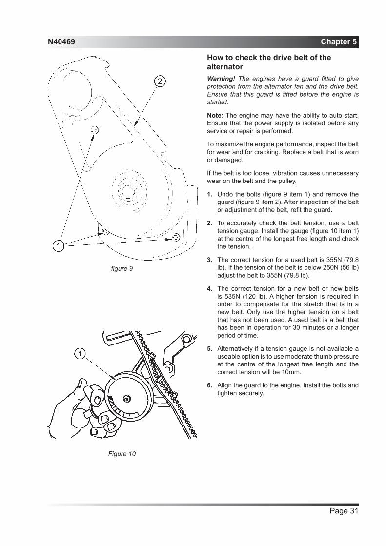
1. Undo the bolts (figure 9 item 1) and remove the guard (figure 9 item 2). After inspection of the belt or adjustment of the belt, refit the guard.
2. To accurately check the belt tension, use a belt tension gauge. Install the gauge (figure 10 item 1) at the centre of the longest free length and check the tension.
3. The correct tension for a used belt is 355N (79.8 lb). If the tension of the belt is below 250N (56 lb) adjust the belt to 355N (79.8 lb).
4. The correct tension for a new belt or new belts is 535N (120 lb). A higher tension is required in order to compensate for the stretch that is in a new belt. Only use the higher tension on a belt that has not been used. A used belt is a belt that has been in operation for 30 minutes or a longer period of time.
5. Alternatively if a tension gauge is not available a useable option is to use moderate thumb pressure at the centre of the longest free length and the correct tension will be 10mm.
6. Align the guard to the engine. Install the bolts and tighten securely.
Figure 10
figure 9

Chapter 5 N40469
Page 32
How to adjust the belt tension1. Loosen the nut and bolt (figure 11 item 1). Then
loosen the nut and bolt (figure 11 item 2).
2. Loosen bolt (figure 12 item 1) and adjust the alternator in order to alter the belt tension. Tighten all bolts for the adjustment of the alternator to 22 Nm (16 lb ft).
3. Refit the belt guard.
Figure 11
Figure 12

N40469 Chapter 5
Page 33
How to check the condition of the heat exchangerThe interval for the maintenance of the tube type heat exchanger (figure 13 item 1) depends on the operating environment of the vessel and on the operating time. The sea water that is circulated through the heat exchanger and the amount of operating time of the vessel affects the following items:
• Cleanliness of the tubes for the heat exchanger
• Effectiveness of the heat exchanger system
Operating in water that contains silt, sediment, salt, algae, etc will adversely affect the heat exchanger system. In addition, intermittent use of the vessel will adversely affect the heat exchanger system.
The following items indicate that the heat exchanger may require cleaning:
• Increased coolant temperature
• Engine overheating
• Excessive pressure drop between the water inlet and the water outlet
An operator that is familiar with the normal operating temperature of the coolant can determine when the coolant temperature is out of the normal range. Inspection and maintenance of the heat exchanger are required if the engine is overheating.
Cleaning the Heat Exchanger1. Drain the fresh water and auxiliary water circuits.
2. Undo the hose clips (figure 14 item 1).
3. Remove bolts (figure 14 item 2).
4. Remove the heat exchanger.
5. Remove the endcap by undoing the bolts (figure 15 item 1).
6. Turn the heat exchanger core upside-down in order to remove debris.
Note: Do not use a high concentration of caustic cleaner to clean the core. A high concentration of caustic cleaner can attack the internal metals of the core and cause leakage. Only use the recommended concentration of cleaner.
Figure 13
Figure 14
Figure 15

Chapter 5 N40469
Page 34
If tubestack is greasy1. Degrease using solvent or by washing with
warm alkaline detergent that is compatible with aluminium.
2. Rinse with water and air dry.
Tubestack is not greasy.1. Wash with warm alkaline detergent that is
compatible with aluminium.
Note: Do not use Acids on aluminium.
2. Rinse with water and air dry.
3. Inspect the core in order to ensure cleanliness. Pressure test the core. Many shops that service radiators are equipped to perform pressure tests. If necessary, repair the core.
4. Reassemble and refit the heat exchanger. For more information on cleaning the core, consult your dealer.

N40469 Chapter 5
Page 35
How to renew the element on the primary fuel filterWarning! Fuel leaked or spilled onto hot surfaces or electrical components can cause a fire. To help prevent possible injury, turn the start switch off when changing fuel filters or water separator elements. Clean up fuel spills immediately.
Note: Refer to, “Cleanliness of Fuel System Components” in the Installation Manual for detailed information on the standards of cleanliness that must be observed during ALL work on the fuel system. It is important to maintain extreme cleanliness when working on the fuel system, since even tiny particles can cause engine or fuel system problems.
It is important to maintain extreme cleanliness when working on the fuel system, since even tiny particles can cause engine or fuel system problems.
Note: Ensure that the engine is stopped before any servicing or repair is performed.
After the engine has stopped, you must wait for 60 seconds in order to allow the fuel pressure to be purged from the high pressure fuel lines before any service or repair is performed on the engine fuel lines. If necessary, perform minor adjustments. Repair any leaks from the low pressure fuel system and from the cooling, lubrication or air systems. Replace any high pressure fuel line that has leaked.
Caution: Do not open high pressure fuel lines to bleed the fuel system as it is self bleeding
Ensure that all adjustments, maintenance and repairs are performed by authorized personnel that have the correct training.
Typical example
1. The engine can have the ability to auto start. Ensure that the power supply is isolated before any service or repair is performed.
2. Turn the fuel supply valve to the OFF position before performing this maintenance.
3. Place a suitable container under the water separator in order to catch any fuel that might spill. Clean up any spilled fuel. Clean the outside of the water separator.
4. Disconnect the wiring harness (5) from the sensor on the bottom of the bowl (4).
5. Open the drain valve (6). Allow the fluid to drain into the container. Tighten the drain valve by hand pressure only.
Figure 16

Chapter 5 N40469
Page 36
6. Rotate the bowl counter clockwise in order to remove the bowl. Remove ‘O’ ring seal (3). Clean the bowl.
7. Use a chain wrench in order to remove old canister (2).
8. Lubricate the ‘O’ ring seal (1) with clean engine oil on the new canister. Install a new canister.
Caution: Do not prefill.
9. Spin on the canister until the ‘O’ ring seal contacts the sealing surface. Then rotate the canister 3/4 of a full turn. Do not use a tool in order to install the canister.
9. Install a new ‘O’ ring seal into the bowl. Lubricate ‘O’ ring seal (3) with clean engine oil. Install the bowl onto the new canister. Tighten the bowl securely. Install the wiring harness to the sensor.
9. Open the fuel supply valve. Remove the container and dispose of the fluid in a safe place..

N40469 Chapter 5
Page 37
How to renew the element on the secondary fuel filterWarning! Fuel leaked or spilled onto hot surfaces or electrical components can cause a fire. To help prevent possible injury, turn the start switch off when changing fuel filters or water separator elements. Clean up fuel spills immediately.
Note: Refer to, “Cleanliness of Fuel System Components” in the Installation Manual for detailed information on the standards of cleanliness that must be observed during ALL work on the fuel system. It is important to maintain extreme cleanliness when working on the fuel system, since even tiny particles can cause engine or fuel system problems.
It is important to maintain extreme cleanliness when working on the fuel system, since even tiny particles can cause engine or fuel system problems.
Note: Ensure that the engine is stopped before any servicing or repair is performed.
After the engine has stopped, you must wait for 60 seconds in order to allow the fuel pressure to be purged from the high pressure fuel lines before any service or repair is performed on the engine fuel lines. If necessary, perform minor adjustments. Repair any leaks from the low pressure fuel system and from the cooling, lubrication or air systems. Replace any high pressure fuel line that has leaked.
Ensure that all adjustments, maintenance and repairs are performed by authorized personnel that have the correct training.
Typical example
1. The engine can have the ability to auto start. Ensure that the power supply is isolated before any service or repair is performed.
2. Turn the fuel supply valve to the OFF position before performing this maintenance.
3. Use a chain wrench in order to remove old canister (2).
4. Lubricate the ‘O’ ring seal (1) with clean engine oil on the new canister. Install the new canister.
Caution: Do not use filter where the wrapping is damaged. Do not prefill.
5. Spin on the canister until the ‘O’ ring seal contacts the sealing surface. Then rotate the canister 3/4 of a full turn. Do not use a tool in order to install the canister.
5. Open the fuel supply valve. Remove the container and dispose of the fluid in a safe place.
Figure 17
Chapter 5 N40469
Page 38
How to renew the lubricating oil of the engineWarning! Discard the used lubricating oil in a safe place and in accordance with local regulations.
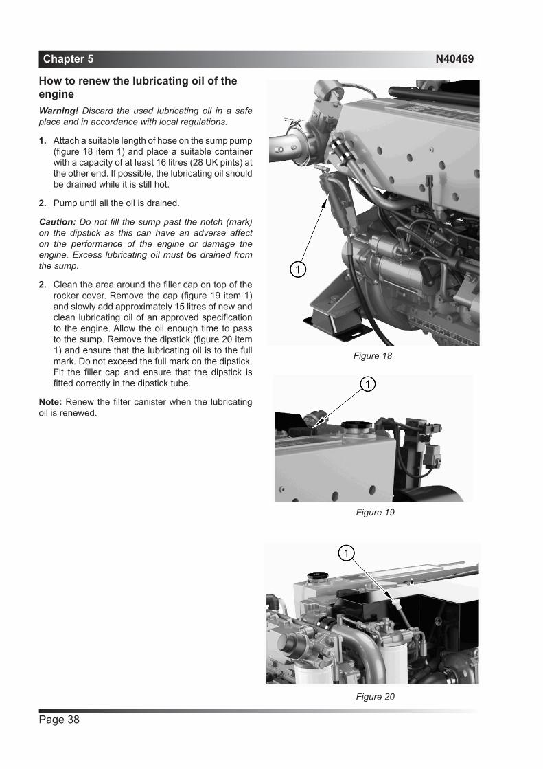
1. Attach a suitable length of hose on the sump pump (figure 18 item 1) and place a suitable container with a capacity of at least 16 litres (28 UK pints) at the other end. If possible, the lubricating oil should be drained while it is still hot.
2. Pump until all the oil is drained.
Caution: Do not fill the sump past the notch (mark) on the dipstick as this can have an adverse affect on the performance of the engine or damage the engine. Excess lubricating oil must be drained from the sump.
2. Clean the area around the filler cap on top of the rocker cover. Remove the cap (figure 19 item 1) and slowly add approximately 15 litres of new and clean lubricating oil of an approved specification to the engine. Allow the oil enough time to pass to the sump. Remove the dipstick (figure 20 item 1) and ensure that the lubricating oil is to the full mark. Do not exceed the full mark on the dipstick. Fit the filler cap and ensure that the dipstick is fitted correctly in the dipstick tube.
Note: Renew the filter canister when the lubricating oil is renewed.
Figure 19
Figure 20
Figure 18

N40469 Chapter 5
Page 39
How to renew the canister of the lubricating oil filterWarning! Discard the used canister and lubricating oil in a safe place and in accordance with local regulations.
1. Put a tray or plastic bag under or around the filter to retain spilt lubricating oil.
2. Remove the filter canister (figure 21 item 1) with a strap wrench or similar tool. Ensure that the adaptor (figure 22 item 1) is secure in the filter head. Then discard the canister.
3. Clean the filter head.
4. Lubricate the top of the new canister seal (figure 22 item 2) with clean engine lubricating oil.
Caution: Do not prefill with oil.
1. Fit the new canister until the surfaces make contact, then tighten it by hand an extra 3/4’s of a turn only. Do not use a strap wrench.
2. Ensure that there is lubricating oil in the sump. Operate the starter motor until the oil pressure warning light is extinguished or there is a reading on the gauge.
3. Operate the engine and check for leakage from the filter. When the engine has cooled, check the oil level on the dipstick and put more oil into the sump, if necessary.
Caution: The canister contains a valve and special tube to ensure that lubricating oil does not drain from the filter. Therefore, ensure that the correct canister is used.
Figure 21
Figure 22

Chapter 5 N40469
Page 40
How to renew the engine breatherCaution: Do not use excessive force to remove the hose (figure 23 item 1) from the breather outlet pipe.
1. Remove the hose (figure 23 item 1) from the engine breather body (figure 23 item 2).
2. Unscrew the breather cap (figure 24 item 1) and pull away from the main body
3. Remove the filter canister (figure 24 item 2) and discard.
4. Insert new filter canister.
4. Replace breather cap and re attach hose
Figure 23
Figure 24

N40469 Chapter 5
Page 41
How to clean the air filter1. Remove nut (1) and washer (2 ).
2. Loosen setscrew (3) and rotate bracket (4) away from the cowl (7).
3. Relax the two hose clips (5) and remove the cleaner assembly.
4. Remove the support tube (9) and filter element (8).
5. Renew the foam element.
6. Refit the element (8) ensuring that the support tube (9) is expanded for correct location within (6) & (7) .
7. Refit mounting hardware.
Figure 25

Chapter 5 N40469
Page 42
How to check the condition of the vibration damperCaution: A vibration damper (figure 27 items 1) should be renewed if there is impact damage to the outer casing or if there is leakage of the viscous fluid from the cover plate.
Check the area around the holes for the damper bolts for cracks and general wear if the damper has become loose in service.
Check that the six bolts (figure 27 item 2) for the viscous damper are tightened correctly:
Tighten the six M12 bolts to 115 Nm (85 lb ft).
If it is necessary to renew the vibration damper refer to the workshop manual.
Figure 27
Figure 26

N40469 Chapter 5
Page 43
How to check the valve tip clearancesCheck the valve lash while the engine is stopped. The temperature of the engine does not change the valve lash setting.
Warning! Accidental engine starting can cause injury or death to personnel. To prevent accidental engine starting, turn the ignition switch to the OFF position and place a ‘DO NOT OPERATE’ tag at the ignition switch location.
Note: Number one cylinder is at the front of the engine or where the vibration damper is. Cylinder number six is at the flywheel end.
TC Compression Stroke1. Remove the valve mechanism cover.
2. Rotate the crankshaft in the direction of engine rotation until the inlet valve of the No. 6 cylinder has opened and the exhaust valve of the No. 6 cylinder has not completely closed. The engine is now at TC compression stroke.
3. Measure the valve lash for the valve when the engine is at TC compression stroke according to the table below. If necessary, make an adjustment to the valves accordingly.
TC Compression
Stroke
Inlet Valves Exhaust Valves
Valve Lash 0.35 mm (0.0138 inch)
0.35 mm (0.0138 inch)
Cylinders 1-2-4 1-3-5
4. Loosen the valve adjustment screw locknut (3) that is on the adjustment screw (2).
4. Place an angled feeler gauge (1) between the rocker arm and the valve. Turn the adjustment screw (2) while the valve adjustment screw locknut (3) is being held from turning. Adjust the valve lash until the correct specification is achieved.
4. After each adjustment, tighten the valve adjustment screw locknut (3) while you hold the valve adjustment screw (2) from turning.
4. Rotate the crankshaft in the direction of engine rotation to TC exhaust stroke (360° from TC compression stroke).
Figure 28

Chapter 5 N40469
Page 44
TC Exhaust Stroke1. Measure the valve lash for the valves when the
engine is at TC exhaust stroke according to the table below. If necessary, make an adjustment to the valves accordingly.
TC Exhaust Stroke
Inlet Valves Exhaust Valves
Valve Lash 0.35 mm (0.0138 inch)
0.35 mm (0.0138 inch)
Cylinders 3-5-6 2-4-6
2. Loosen the valve adjustment screw locknut (3) that is on the adjustment screw (2).
3. Place an angled feeler gauge (1) between the rocker arm and the valve. Turn the adjustment screw (2) while the valve adjustment screw locknut (3) is being held from turning. Adjust the valve lash until the correct specification is achieved.
4. After each adjustment, tighten the valve adjustment screw locknut while you hold the valve adjustment screw (2) from turning.
5. Install the valve mechanism cover.
If the valve lash requires adjustment several times in a short period of time, excessive wear exists in a different part of the engine. Find the problem and make necessary repairs in order to prevent more damage to the engine.
• Not enough valve lash can be the cause of rapid wear of the camshaft and valve lifters.
• Not enough valve lash can indicate that the seats for the valves are worn.
Valves become worn due to the following causes:
• Fuel injection nozzles that operate incorrectly
• Excessive dirt and oil are present on the filters for the inlet air.
• Incorrect fuel settings on the fuel injection pump.
• The load capacity of the engine is frequently exceeded.
• Too much valve lash can cause broken valve stems, springs, and spring retainers.
• Too much valve lash can be an indication of the following problems:
• Worn camshaft and valve lifters
• Worn rocker arms

N40469 Chapter 5
Page 45
• Bent pushrods
• Broken socket on the upper end of a pushrod
• Loose adjustment screw for the valve lash
If the camshaft and valve lifters show rapid wear, look for fuel in the lubrication oil or dirty lubrication oil as a possible cause.
• Valve Lash Check
CorrosionThis can occur when two different metals are in contact near to, or in, sea water. For example, a brass or bronze pipe fitted into aluminium can cause rapid corrosion. For this reason, special precautions are necessary when an engine is installed. In this situation, some components will be connected to a sacrificial anode fitted to the hull. Specialist manufacturers will advise on the maintenance of these anodes.
Supplementary toolsA general tool kit and an on-board repair kit are available from your Perkins Distributor. It is recommended that the tools and other parts, listed below, are also retained on-board:
Wire, 20 SWG (1mm in diameter)
Insulation tape
Jointing compound
Magnet (keep this away from the compass)
Mechanical fingers
Self-gripping wrench
Suitable lagging material
Rubber olives for the low-pressure fuel system
Extra blades for a small hacksaw

Chapter 5 N40469
Page 46

N40469 Chapter 6
Page 47
Engine preservation
IntroductionThe recommendations indicated below are designed to prevent damage to the engine when it is withdrawn from service for a prolonged period. Use these procedures if the engine is to be withdrawn from service. The instructions for the use of POWERPART products are given on the outside of each container.
Procedure1. Completely clean the outside of the engine.
2. When a preservative fuel is to be used, drain the fuel system and fill it with the preservative fuel. POWERPART Lay-Up 1 can be added to the normal fuel to change it to a preservative fuel. If preservative fuel is not used, the system can be completely filled with normal fuel but the fuel must be drained and discarded at the end of the storage period together with the fuel filter canister.
3. Operate the engine until it is warm. Then correct leakages of fuel, lubricating oil or air. Stop the engine and drain the lubricating oil from the sump.
4. Renew the canister of the lubricating oil filter.
5. Fill the sump to the full mark with new and clean lubricating oil and add POWERPART Lay-up 2 to the oil to protect the engine against corrosion. If POWERPART Lay-Up 2 is not available, use a correct preservative fluid instead of the lubricating oil. If a preservative fluid is used, this must be drained and the lubricating oil sump must be filled to the correct level with normal lubricating oil at the end of the storage period.
6. Drain the coolant circuit. In order to protect the cooling system against corrosion, fill it with an approved antifreeze mixture because this gives protection against corrosion.
Caution: If protection against frost is not necessary and a corrosion inhibitor is to be used, it is recommended that you consult the Service Department, Wimborne Marine Power Centre.
7. Operate the engine for a short period in order to circulate the lubricating oil and the coolant in the engine.
8. Close the seacock and drain the auxiliary water cooling system.
Caution: The auxiliary water system cannot be drained completely. If the system is drained for engine preservation purposes or for protection from frost, the system must be filled again with an approved antifreeze mixture.
9. Remove the impeller from the auxiliary water pump and put the impeller in a dark place for storage. Before the impeller is fitted at the end of the storage period, lubricate lightly the blades and each end of the impeller and the inside of the pump with Spheerol SX2 grease or glycerine.
Caution: The auxiliary water pump must never run in a dry condition because this can damage the impeller blades.
10. Spray POWERPART Lay-Up 2 into the induction manifold. Seal the manifold and breather outlet with waterproof tape.
11. Remove the exhaust pipe. Spray POWERPART Lay-Up 2 into the exhaust manifold. Seal the manifold with waterproof tape.
12. Disconnect the battery. Then put the battery into safe storage in a fully charged condition. Before the battery is put into storage, protect its terminals against corrosion. POWERPART Lay-Up 3 can be used on the terminals.
13. Seal the vent pipe of the fuel tank or the fuel filler cap with waterproof tape.

Chapter 6 N40469
Page 48
14. Remove the alternator drive belt and put it into storage.
15. In order to prevent corrosion, spray the engine with POWERPART Lay-Up 3. Do not spray the area inside the alternator cooling fan.
16. If the transmission is not to be used for at least a year, fill the gearbox completely with its normal lubricating oil. This will have to be drained and the normal amount of new lubricating oil added when the engine is returned to service.
Caution: After a period in storage, but before the engine is started, operate the starter motor with the stop switch held in the “STOP” position until oil pressure is indicated. Oil pressure is indicated when the low pressure warning light is extinguished. If a solenoid stop control is used on the fuel injection pump, it must be disconnected for this operation.
If the engine protection is done correctly according to the above recommendations, no corrosion damage will normally occur. Wimborne Marine Power Centre are not responsible for damage which may occur when an engine is in storage after a period in service.
How to add antifreeze to the auxiliary water system for engine preservation purposesBefore antifreeze is added to the auxiliary water system the system should be flushed out with fresh water. To do this operate the engine for one to two minutes with the seacock closed and with a supply of fresh water through the open top of the auxiliary water strainer.
1. Obtain two empty, clean containers each with a capacity of approximately 9,0 litres (2 UK gallons) 9.6 US quarts. Also obtain 4,5 litre (1 UK gallon) 5 US quarts of POWERPART antifreeze.
2. Remove the hose from the connection on the exhaust elbow and put the end of the hose into one of the containers.
3. Remove the cover from the top of the auxiliary water strainer, and with the seacock closed, add some antifreeze through the open top of the auxiliary water strainer. Start the engine and run the engine at idle speed, then continue to add the remainder of the antifreeze through the open top of the strainer.
4. Operate the engine for several minutes. During this period, change the containers around, pour the antifreeze/water solution from the container at the outlet (hose end) into the strainer.
5. When the antifreeze is mixed thoroughly and has been circulated through the auxiliary water system, stop the engine. Fit the top of the auxiliary water strainer.

N40469 Chapter 7
Page 49
Parts and service
IntroductionIf problems occur with your engine or with the components fitted onto it, your Perkins distributor can make the necessary repairs and will ensure that only the correct parts are fitted and that the work is done correctly.
Service literatureWorkshop manuals, Installation drawings and other service publications are available from your Perkins distributor at a nominal cost.
TrainingLocal training for the correct operation, service and overhaul of engines is available at Perkins distributor. If special training is necessary, your Perkins distributor can advise you how to obtain it at Wimborne Marine Power Centre or the Perkins Customer Training Department, Peterborough, or other main centres.
On-board repair kitThe contents of this kit has been carefully prepared to ensure that it is correct for the original engine specification and the owner’s/operator’s needs.

Chapter 7 N40469
Page 50
POWERPART recommended consumable productsPerkins have made available the products recommended below in order to assist in the correct operation, service and maintenance of your engine and your machine. The instructions for the use of each product are given on the outside of each container. These products are available from your Perkins distributor or Wimborne Marine Power Centre.
POWERPART AntifreezeProtects the cooling system against frost and corrosion.
POWERPART Easy FlushCleans the cooling system.
POWERPART Gasket and flange sealantTo seal flat faces of components where no joint is used. Especially suitable for aluminium components.
POWERPART Gasket removerAn aerosol for the removal of sealants and adhesives.
POWERPART GriptiteTo improve the grip of worn tools and fasteners.
POWERPART Hydraulic threadsealTo retain and seal pipe connections with fine threads. Especially suitable for hydraulic and pneumatic systems.
POWERPART Industrial grade super glueInstant adhesive designed for metals, plastics and rubbers.
POWERPART Lay-Up 1A diesel fuel additive for protection against corrosion.
POWERPART Lay-Up 2Protects the inside of the engine and of other closed systems.
POWERPART Lay-Up 3Protects outside metal parts.
POWERPART Metal repair puttyDesigned for external repair of metal and plastic.
POWERPART Pipe sealant and sealant primerTo retain and seal pipe connections with coarse threads. Pressure systems can be used immediately.
POWERPART Retainer (high strength)To retain components which have an interference fit. Currently Loctite 638.
POWERPART Safety cleanerGeneral cleaner in an aerosol container
POWERPART Silicone adhesiveAn RTV silicone adhesive for application where low pressure tests occur before the adhesive sets. Used for sealing flange where oil resistance is needed and movement of the joint occurs.
POWERPART Silicone RTV sealing and jointing compoundSilicone rubber sealant which prevents leakage through gaps. Currently Hylosil.
POWERPART Stud and bearing lockTo provide a heavy duty seal to components that have a light interference fit.
POWERPART Threadlock and nutlockTo retain small fasteners where easy removal is necessary.
POWERPART Universal jointing compoundUniversal jointing compound which seals joints. Currently Hylomar.

N40469 Chapter 8
Page 51
General data
EngineNumber of cylinders.........................................................................................................................................6
Cylinder arrangement ..............................................................................................................................In line
Cycle............................................................................................................................................... Four stroke
Induction system:.....................................................................................................Turbocharged aftercooling
Combustion system ...................................................................................................................Direct injection
Nominal bore ......................................................................................................................... 105 mm (4.13 in)
Stroke .................................................................................................................................... 127 mm (5.00 in)
Compression ratio: ................................................................................................................................. 16.2:1
Cubic capacity .......................................................................................................................6.6 litres (365 in3)
Firing order ................................................................................................................................. 1, 5, 3, 6, 4, 2
Valve tip clearances (hot or cold):
- Inlet................................................................................................................................. 0.35 mm (0.0138 in)
- Exhaust .......................................................................................................................... 0.35 mm (0.0138 in)
Lubricating oil pressure (minimum atmaximum engine speed and normalengine temperature) .............................................................................................................................. 3.6 bar
Capacity of lubricating oil sump:- Maximum .................................................................................................................... 15.0 litres (3.3 gallons)
Coolant capacity (closed circuit) ....................................................26.3 litres (46.26 UK pints) 27.7 US quarts
Direction of rotation ....................................................................................................Clockwise from the front
Batteries ....................................Two 12 volt 510 amperes (BS3911) or two 12 volt 790 amperes (SAE J537)
Weight of the engine with coolant and engine lubricating oil, M300C, M250C .......................738 kg (1627lbs)
Weight of the engine with coolant and engine lubricating oil, M216C, M190C .......................736 kg (1623lbs)

Chapter 8 N40469
Page 52

California
Proposition 65 Warning
Diesel engine exhaust and some of its constituents are known to the State of California to cause cancer, birth
defects, and other reproductive harm.

All information in this document is substantially correct at time of printing and may be altered subsequently. Part No. N40469 issue 3Produced in England ©2013 by Wimborne Marine Power Centre
Wimborne Marine Power Centre22 Cobham Road, Ferndown Industrial Estate, Wimborne, Dorset, BH21 7PW, England.Tel: +44 (0)1202 796000, Fax: +44 (0)1202 796001E-mail: [email protected]
Web: www.perkins.com/Marine