user's information manual - lennoxpros.com · high altitude derate page 9 ... take care when...
TRANSCRIPT

USER'S INFORMATIONMANUAL
LGH/LCH036, 048, 060, 072(3, 4, 5 & 6 Tons)
This book includes the following manuals:
UNIT INSTALLATION INSTRUCTIONS 507410-02
OWNER'S MANUAL 507246-02
AGENCY MANUAL 506373-02
IMC MANUAL 507241-02
ECONOMIZER INSTRUCTIONS 507225-01
IMC MODULE INSTRUCTIONS (LONTALK GATEWAY) 506217-01
IMC MODULE INSTRUCTIONS (LONTALK PRODIGY) 506693-01
WARRANTY W-022-L3


2014Litho U.S.A.
WARNINGImproper installation, adjustment, alteration, service or maintenance can cause property damage,personal injury or loss of life. Installation and service must be performed by a licensed professionalHVAC installer or equivalent, service agency, or thegas supplier
Table Of Contents
Dimensions Page 2. . . . . . . . . . . . . . . . . . . . . . . . . . . . . . . . .
Parts Arrangements Page 3. . . . . . . . . . . . . . . . . . . . . . . . .
Shipping and Packing List Page 4. . . . . . . . . . . . . . . . . . . .
General Page 4. . . . . . . . . . . . . . . . . . . . . . . . . . . . . . . . . . . .
Requirements Page 4. . . . . . . . . . . . . . . . . . . . . . . . . . . . . . .
Unit Support Page 5. . . . . . . . . . . . . . . . . . . . . . . . . . . . . . . .
Duct Connection Page 5. . . . . . . . . . . . . . . . . . . . . . . . . . . .
Rigging Unit For Lifting Page 5. . . . . . . . . . . . . . . . . . . . . . .
Horizontal Air Discharge Page 6. . . . . . . . . . . . . . . . . . . . . .
Condensate Drains Page 6. . . . . . . . . . . . . . . . . . . . . . . . . .
Gas Piping Page 8. . . . . . . . . . . . . . . . . . . . . . . . . . . . . . . . .
Pressure Test Gas Piping Page 9. . . . . . . . . . . . . . . . . . . . .
INSTALLATIONINSTRUCTIONS
LGH/LCH036, 048,060 & 0723, 4, 5 and 6 Ton
GAS AND COOLING PACKAGED UNITS507410-0212/2014Supersedes 8/2014
High Altitude Derate Page 9. . . . . . . . . . . . . . . . . . . . . . . . .
Electrical Connections Page 9. . . . . . . . . . . . . . . . . . . . . . .
Blower Operation and Adjustments Page 12. . . . . . . . . . . .
Cooling Start-Up Page 28. . . . . . . . . . . . . . . . . . . . . . . . . . . .
Cooling Operation Page 38. . . . . . . . . . . . . . . . . . . . . . . . . . .
Gas Heat Start-Up Page 39. . . . . . . . . . . . . . . . . . . . . . . . . . .
Heating Operation and Adjustments Page 40. . . . . . . . . . . .
Electric Heat Start-Up Page 40. . . . . . . . . . . . . . . . . . . . . . . .
Advanced Air Flow Control Start-Up Page 41. . . . . . . . . . . .
Hot Gas Reheat Startup Page 43. . . . . . . . . . . . . . . . . . . . . .
Service Page 44. . . . . . . . . . . . . . . . . . . . . . . . . . . . . . . . . . . .
Factory Unit Controller Settings Page 48. . . . . . . . . . . . . . .
CAUTIONDanger of sharp metallic edges. Can cause injury.Take care when servicing unit to avoid accidentalcontact with sharp edges.
RETAIN THESE INSTRUCTIONS FOR FUTURE REFERENCE
LG SHOWN

Page 2
LGH/LCH036, 048, 060, 072
LGH/LCH036, 048, 060, & 072 DIMENSIONS in. - Gas heat section shown
45(1143)
END VIEW
1 (25)
47 (1194)BASE
38−
7/8
(987
) 03
6 th
ru 0
4846−7
/8 (
1191
) 06
0 th
ru 0
72
DD CC
BBAA
FF
EE
11(279)
16−1/4(413)
18(457)
20(508)
5 (127)
47 (1194)BASE
BOTTOMSUPPLY
AIROPENING
TOP VIEW (Base)
CENTEROF
GRAVITY
9−1/2(241)6−5/8
(168)
26−1/2(673)
5−5/8(143)
29(737)
7 (178) BOTTOMRETURN
AIROPENING
BOTTOMCONDENSATE OUTLET
25−3/4(654)
BOTTOM POWER ENTRY3 X 8 (76 X 203)
18−3/8(467)
19−1/2(495)
5−1/2(140)
FORKLIFT SLOTS(Front, Back and
Blower End)
HORIZONTALRETURN AIR
OPENING(Without Economizer)
HORIZONTALSUPPLY AIR
OPENING
2 (51)11
(279)
29(737)
20(508)
5−1/2(140)
BACK VIEW
CONDENSATEOUTLET
(EITHER SIDE)
3−1/2 (89)
83−1/4(2115)
85−1/4 (2165)BASE
26−1/2(673)
5−1/2(140)
GASINLET
FLUE/VENTOUTLET
LIFTING HOLES(For rigging)
SIDE VIEW
27(686)
15 (381)
ELECTRICALINLET
1 (25)35−
3/8
(899
) 03
6 th
ru 0
4843−3
/8 (
1102
) 06
0 th
ru 0
72
85-1/4 (2165)BASE
38-7
/8 (
987)
036 thru
048
46-7
/8 (
1191)
060 thru
072

Page 3
LGH/LCH036, 048, 060, 072
LGH036, 048, 060, & 072 PARTS ARRANGEMENT
EVAPORATORCOIL
CONDENSERFAN
CONDENSERCOIL
COMPRESSOR
CONDENSATEDRAIN
FILTERS (4)
036, 048:16 X 20 X 2”060, 072: 20 X 20 X 2”
ECONOMIZER(OPTIONAL)
GAS VALVEBURNERS
COMBUSTIONAIR INDUCER
BLOWERMOTOR
(BELT DRIVE SHOWN)
TXV
UNITCONTROLLER
REHEAD COIL(OPTIONAL)
BLOWER
COILGUARDS
(OPTIONAL)
LCH036, 048, 060, & 072 PARTS ARRANGEMENT
ELECTRIC HEAT(Optional)
EVAPORATORCOIL
CONDENSERFAN
CONDENSERCOIL
COMPRESSOR
CONDENSATEDRAIN
ECONOMIZER(OPTIONAL)
BLOWER
BLOWERMOTOR
(BELT DRIVE SHOWN)
FILTERS (4)
036, 048:16 X 20 X 2”060, 072: 20 X 20 X 2”
TXV
UNITCONTROLLER
REHEAT COIL(OPTIONAL)

Page 4
LGH/LCH036, 048, 060, 072
Shipping and Packing List
Package 1 of 1 contains:
1- Assembled unit
Check unit for shipping damage. Receiving party should
contact last carrier immediately if shipping damage is found.
General
These instructions are intended as a general guide
and do not supersede local codes in any way.
Authorities having jurisdiction should be consulted
before installation.
The LGH units are available in three heating inputs. The
LCH cooling packaged rooftop unit is the same basic
design as the LGH unit except for the heating section.
Optional electric heat is available for LCH units. LGH and
LCH units have identical refrigerant circuits with
respective 3, 4, 5, and 6 ton cooling capacities.
Units come standard with a lightweight, all-aluminum
condenser coil. Units are also available with an optional
fin/tube condenser coil.
In addition to standard heating and cooling, hot gas
reheat units provide a dehumidifying mode of operation.
Refer to Reheat Operation section.
Units may be equipped with a Unit Controller that is
factory-configured for “Advanced Air Flow Control”. This
option allows the installer to enter both the
design-specified supply air CFM and outdoor air CFM.
See the Advanced Air Flow Control Start-Up section.
These units are equipped with a variable speed, direct
drive blower and an economizer.
Availability of units and options varies by brand.
Requirements
See figure 1 for unit clearances.
WARNINGElectric shock hazard and danger ofexplosion. Can cause injury, death orproduct or property damage. Turn offgas and electrical power to unit beforeperforming any maintenance orservicing operations on the unit. Followlighting instructions attached to unitwhen putting unit back into operationand after service or maintenance.
IMPORTANTThe Clean Air Act of 1990 bans the intentional venting of refrigerant (CFC's and HCFC's) as of July 1,1992. Approved methods of recovery, recycling orreclaiming must be followed. Fines and/or incarceration may be levied for non-compliance.
NOTICERoof Damage!This system contains both refrigerant and oil.Some rubber roofing material may absorb oil,causing the rubber to swell. Bubbles in the rubberroofing material can cause leaks. Protect the roofsurface to avoid exposure to refrigerant and oilduring service and installation. Failure to followthis notice could result in damage to roof surface.
UNIT CLEARANCES
C
D
B
A
FIGURE 1
1UnitClearance
Ain.(mm)
Bin.(mm)
Cin.(mm)
Din.(mm)
TopClearance
ServiceClearance
48(1219)
36(914)
36(914)
36(914)
Unobstructed
Clearance toCombustibles
36(914)
1(25)
1(25)
1(25)
Unobstructed
Minimum Operation Clearance
36(914)
36(914)
36(914)
36(914)
Unobstructed
Note - Entire perimeter of unit base requires support when elevated above
mounting surface.
1 Service Clearance - Required for removal of serviceable parts.
Clearance to Combustibles - Required clearance to combustible material
(gas units).
Minimum Operation Clearance - Required clearance for proper unit operation.
Use of this unit as a construction heater or air conditioner
is not recommended during any phase of construction.
Very low return air temperatures, harmful vapors and
operation of the unit with clogged or misplaced filters will
damage the unit.
If this unit has been used for heating or cooling of
buildings or structures under construction, the following
conditions must be met or the warranty will be void:
� A room thermostat must control the unit. The use of
fixed jumpers that will provide continuous heating or
cooling is not allowed.
� A pre-filter must be installed at the entry to the return
air duct.
� The return air duct must be provided and sealed to
the unit.
� Return air temperature range between 55°F (13°C)
and 80°F (27°C) must be maintained.
Page 5
LGH/LCH036, 048, 060, 072
� Air filters must be replaced and pre-filters must be
removed upon construction completion.
� The input rate and temperature rise must be set per
the unit rating plate.
� The heat exchanger, components, duct system, air
filters and evaporator coil must be thoroughly
cleaned following final construction clean-up.
� The unit operating conditions (including airflow,
cooling operation, ignition, input rate, temperature
rise and venting) must be verified according to these
installation instructions.
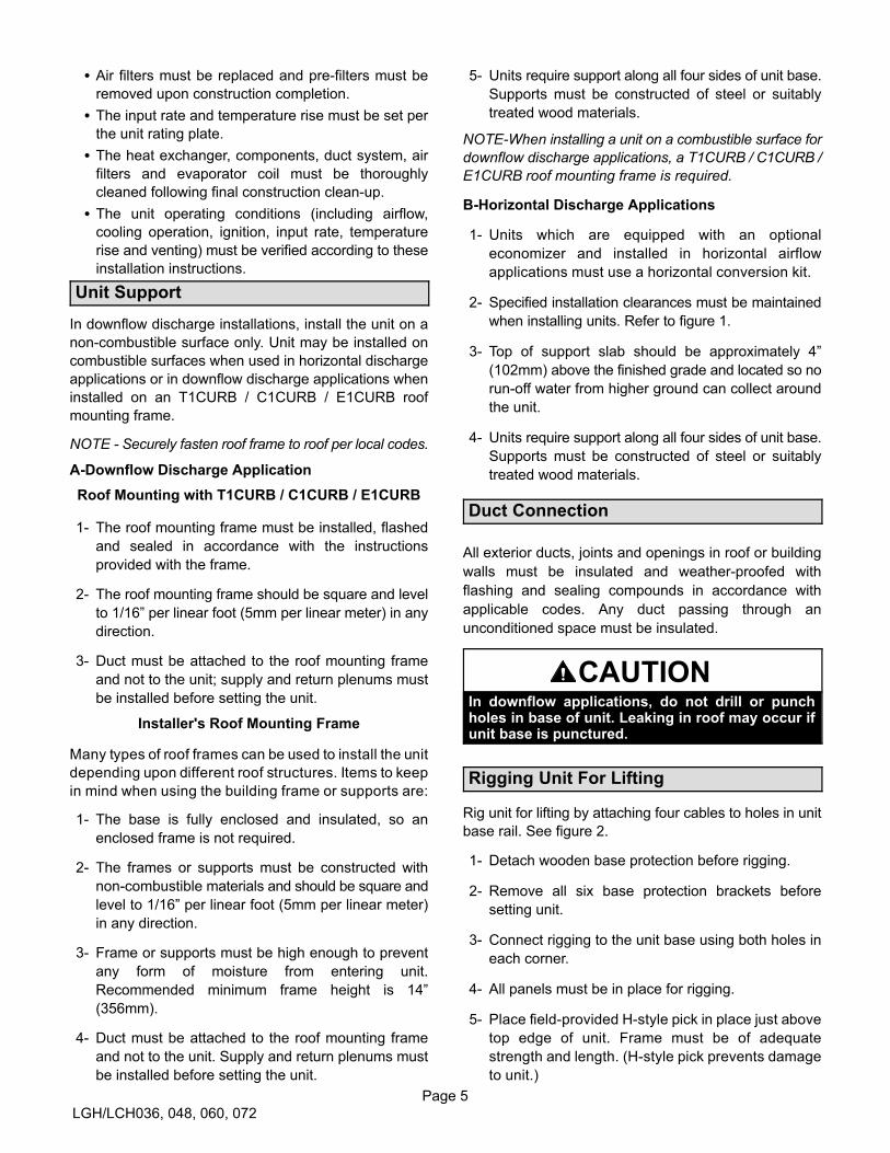
Unit Support
In downflow discharge installations, install the unit on a
non-combustible surface only. Unit may be installed on
combustible surfaces when used in horizontal discharge
applications or in downflow discharge applications when
installed on an T1CURB / C1CURB / E1CURB roof
mounting frame.
NOTE - Securely fasten roof frame to roof per local codes.
A-Downflow Discharge Application
Roof Mounting with T1CURB / C1CURB / E1CURB
1- The roof mounting frame must be installed, flashed
and sealed in accordance with the instructions
provided with the frame.
2- The roof mounting frame should be square and level
to 1/16” per linear foot (5mm per linear meter) in any
direction.
3- Duct must be attached to the roof mounting frame
and not to the unit; supply and return plenums must
be installed before setting the unit.
Installer's Roof Mounting Frame
Many types of roof frames can be used to install the unit
depending upon different roof structures. Items to keep
in mind when using the building frame or supports are:
1- The base is fully enclosed and insulated, so an
enclosed frame is not required.
2- The frames or supports must be constructed with
non-combustible materials and should be square and
level to 1/16” per linear foot (5mm per linear meter)
in any direction.
3- Frame or supports must be high enough to prevent
any form of moisture from entering unit.
Recommended minimum frame height is 14”
(356mm).
4- Duct must be attached to the roof mounting frame
and not to the unit. Supply and return plenums must
be installed before setting the unit.
5- Units require support along all four sides of unit base.
Supports must be constructed of steel or suitably
treated wood materials.
NOTE-When installing a unit on a combustible surface for
downflow discharge applications, a T1CURB / C1CURB /
E1CURB roof mounting frame is required.
B-Horizontal Discharge Applications
1- Units which are equipped with an optional
economizer and installed in horizontal airflow
applications must use a horizontal conversion kit.
2- Specified installation clearances must be maintained
when installing units. Refer to figure 1.
3- Top of support slab should be approximately 4”
(102mm) above the finished grade and located so no
run-off water from higher ground can collect around
the unit.
4- Units require support along all four sides of unit base.
Supports must be constructed of steel or suitably
treated wood materials.
Duct Connection
All exterior ducts, joints and openings in roof or building
walls must be insulated and weather-proofed with
flashing and sealing compounds in accordance with
applicable codes. Any duct passing through an
unconditioned space must be insulated.
CAUTIONIn downflow applications, do not drill or punchholes in base of unit. Leaking in roof may occur ifunit base is punctured.
Rigging Unit For Lifting
Rig unit for lifting by attaching four cables to holes in unit
base rail. See figure 2.
1- Detach wooden base protection before rigging.
2- Remove all six base protection brackets before
setting unit.
3- Connect rigging to the unit base using both holes in
each corner.
4- All panels must be in place for rigging.
5- Place field‐provided H‐style pick in place just above
top edge of unit. Frame must be of adequate
strength and length. (H-style pick prevents damage
to unit.)

Page 6
LGH/LCH036, 048, 060, 072
LG
LC
FIGURE 2
IMPORTANT - ALLPANELS MUSTBE IN PLACE
FOR RIGGING.
LIFTING POINT SHOULDBE DIRECTLY ABOVECENTER OF GRAVITY
*Maximum weight with all availablefactory-installed accessories.
435
423
Unit*Weight
Lbs. Kg.
CAUTION - Donot walk on unit.
960
933
Horizontal Air Discharge
Unit is shipped with panels covering the horizontal supply
and return air openings. Remove horizontal covers and
place over downflow openings for horizontal air discharge.
See figure 3. Secure in place with sheet metal screws.
Units Equipped With An Optional Economizer
1- Remove the horizontal supply air cover and position
over the downflow supply air opening. Secure with
sheet metal screws.
2- Leave the horizontal return air cover in place.
3- Locate the separately ordered horizontal air
discharge kit. Place the kit panel over the downflow
return air opening.
4- Remove and retain the barometric relief dampers and
lower hood.
FIGURE 3
DOWNFLOWRETURN AIR
OPENING
UNIT SUPPLY AND RETURN AIR OPENINGS
DOWNFLOWSUPPLY AIR
OPENING
HORIZONTALRETURN AIR
OPENING
HORIZONTALSUPPLY AIR
OPENING
5- Install return air duct beneath outdoor air intake. See
figure 4. Install barometric relief damper in lower
hood and install in ductwork as shown in figure 4.
FIGURE 4
HORIZONTAL RETURN AIR DUCTWORKWITH ECONOMIZER
HORIZONTALRETURN AIR
DUCT
INSTALL BAROMETRIC RELIEF DAMPERSAND HOOD IN RETURN AIR DUCT
UNITUNIT
Condensate Drains
Make drain connection to the drain coupling provided on
unit. Older model units have a 3/4” N.P.T. coupling and
newer model units have a 1” N.P.T. coupling.
Note - The drain pan is made with a glass reinforced
engineered plastic capable of withstanding typical joint
torque but can be damaged with excessive force. Tighten
pipe nipple hand tight and turn an additional quarter turn.
A trap must be installed between drain connection and an
open vent for proper condensate removal. See figure 5 or
6. It is sometimes acceptable to drain condensate onto
the roof or grade; however, a tee should be fitted to the
trap to direct condensate downward. The condensate line
must be vented. Check local codes concerning
condensate disposal. Refer to pages 1 and 2 for
condensate drain location.
FIGURE 5
ÁÁÁÁÁÁÁÁÁÁÁÁÁ
UNIT
Minimum Pitch
1” (25 mm) per
10' (3 m) of line
MOUNTINGFRAME
OPEN VENT
CONDENSATE SIDE DRAIN CONNECTION
NOTE - Allow clearance toopen doors when installingcondensate piping.
CAULK AROUND CONDENSATE COUPLING
Page 7
LGH/LCH036, 048, 060, 072
FIGURE 6
UNIT
Minimum Pitch1” (25 mm) per 10'
(3 m) of line
MOUNTINGFRAME
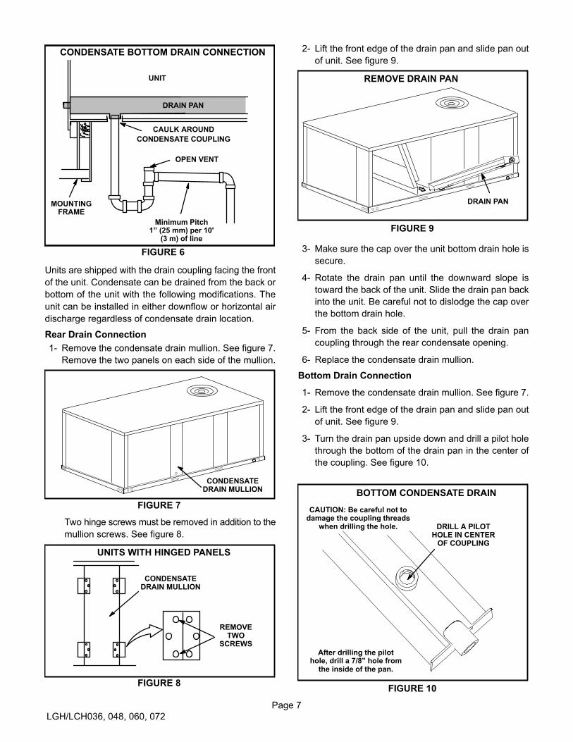
CONDENSATE BOTTOM DRAIN CONNECTION
OPEN VENT
CAULK AROUND
CONDENSATE COUPLING
DRAIN PAN
Units are shipped with the drain coupling facing the front
of the unit. Condensate can be drained from the back or
bottom of the unit with the following modifications. The
unit can be installed in either downflow or horizontal air
discharge regardless of condensate drain location.
Rear Drain Connection
1- Remove the condensate drain mullion. See figure 7.
Remove the two panels on each side of the mullion.
FIGURE 7
CONDENSATEDRAIN MULLION
Two hinge screws must be removed in addition to the
mullion screws. See figure 8.
FIGURE 8
CONDENSATEDRAIN MULLION
REMOVETWO
SCREWS
UNITS WITH HINGED PANELS
2- Lift the front edge of the drain pan and slide pan out
of unit. See figure 9.
FIGURE 9
REMOVE DRAIN PAN
DRAIN PAN
3- Make sure the cap over the unit bottom drain hole is
secure.
4- Rotate the drain pan until the downward slope is
toward the back of the unit. Slide the drain pan back
into the unit. Be careful not to dislodge the cap over
the bottom drain hole.
5- From the back side of the unit, pull the drain pan
coupling through the rear condensate opening.
6- Replace the condensate drain mullion.
Bottom Drain Connection
1- Remove the condensate drain mullion. See figure 7.
2- Lift the front edge of the drain pan and slide pan out
of unit. See figure 9.
3- Turn the drain pan upside down and drill a pilot hole
through the bottom of the drain pan in the center of
the coupling. See figure 10.
FIGURE 10
BOTTOM CONDENSATE DRAIN
DRILL A PILOTHOLE IN CENTER
OF COUPLING
After drilling the pilothole, drill a 7/8” hole from
the inside of the pan.
CAUTION: Be careful not todamage the coupling threads
when drilling the hole.

Page 8
LGH/LCH036, 048, 060, 072
4- From the inside of the pan, use a Vari-Bit® bit to
enlarge the hole to 7/8”. Do not damage coupling
threads.
5- Remove the cap over the unit bottom drain hole.
6- Slide the drain pan back into the unit.
7- From the back side of the unit, pull the drain pan
coupling through the rear condensate opening.
8- From the front side of the unit, move the drain pan
until the bottom coupling settles into the unit bottom
drain opening. Once in place, check to make sure the
coupling is still positioned through the rear
condensate drain hole.
9- Use a field-provided 3/4” plug to seal side drain
connection.
10- Replace the condensate drain mullion.
Connect Gas Piping (Gas Units)
Before connecting field-provided piping, check with gas
company or authorities having jurisdiction for local code
requirements. When installing gas supply piping, length
of run from gas meter must be considered in determining
pipe size for 0.5” w.c. (.12kPa) maximum pressure drop.
Do not use supply pipe smaller than unit gas connection.
Operating pressures at the unit gas connection must be
as shown in table 1.
TABLE 1OPERATING PRESSURE AT GAS CONNECTION “w.c.
Natural Gas LP / Propane Gas
Min. Max. Min. Max.
036-072 4.5 10.5 11 13
When making piping connections a drip leg should be
installed on vertical pipe runs to serve as a trap for
sediment or condensate. A 1/8” N.P.T. plugged tap is
located on gas valve for test gauge connection. Refer to
Heating Start-Up section for tap location. Install a ground
joint union between the gas control manifold and the
main manual shut-off valve. See figure 11 for gas supply
piping entering outside the unit. Figure 12 shows
complete bottom gas entry piping.
Compounds used on threaded joints of gas piping shall be
resistant to the action of liquified petroleum gases.
Do not use Teflon® tape to seal gas piping. Use a
moderate amount of pipe compound on the gas pipe only.
Make sure the two end threads are bare.
CAUTION
If a flexible gas connector is required or allowed bythe authority that has jurisdiction, black iron pipeshall be installed at the gas valve and extend outside the furnace cabinet.
WARNING
Do not exceed 600 in-lbs (50 ft.-lbs) torque when attaching the gas piping to the gas valve.
IMPORTANT
Compounds used on threaded joints of gas pipingmust be resistant to the actions of liquified petroleum gases.
FIGURE 11
TO GASSUPPLY
MANUAL MAIN
SHUT-OFF VALVE
GAS PIPING
SUPPORT
GROUND
JOINT UNION
(REFER TO
LOCAL CODES)
DRIP LEG
OUTSIDE OF UNIT GAS PIPE CONNECTION
TO GASVALVE
Page 9
LGH/LCH036, 048, 060, 072
DRIP LEG
MANUAL MAIN
SHUT-OFF VALVE
GROUND
JOINT UNION
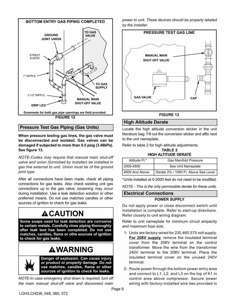
FIGURE 12
BOTTOM ENTRY GAS PIPING COMPLETED
7” NIPPLE
STREETELBOW
TO GASSUPPLY
TO GASVALVE
Grommets for both gas pipe openings are field provided.
2-1/2” NIPPLE
Pressure Test Gas Piping (Gas Units)
When pressure testing gas lines, the gas valve must
be disconnected and isolated. Gas valves can be
damaged if subjected to more than 0.5 psig (3.48kPa).
See figure 13.
NOTE-Codes may require that manual main shut-off
valve and union (furnished by installer) be installed in
gas line external to unit. Union must be of the ground
joint type.
After all connections have been made, check all piping
connections for gas leaks. Also check existing unit gas
connections up to the gas valve; loosening may occur
during installation. Use a leak detection solution or other
preferred means. Do not use matches candles or other
sources of ignition to check for gas leaks.
CAUTIONSome soaps used for leak detection are corrosiveto certain metals. Carefully rinse piping thoroughlyafter leak test has been completed. Do not usematches, candles, flame or othe sources of ignitionto check for gas leaks.
WARNINGDanger of explosion. Can cause injuryor product or property damage. Do notuse matches, candles, flame or othersources of ignition to check for leaks.
NOTE-In case emergency shut down is required, turn off
the main manual shut-off valve and disconnect main
power to unit. These devices should be properly labeled
by the installer.
GAS VALVE CAP
MANUAL MAIN
SHUT-OFF VALVE
FIGURE 13
PRESSURE TEST GAS LINE
High Altitude Derate
Locate the high altitude conversion sticker in the unit
literature bag. Fill out the conversion sticker and affix next
to the unit nameplate.
Refer to table 2 for high altitude adjustments.
TABLE 2HIGH ALTITUDE DERATE
Altitude Ft.* Gas Manifold Pressure
2000-4500 See Unit Nameplate
4500 And Above Derate 2% / 1000 Ft. Above Sea Level
*Units installed at 0-2000 feet do not need to be modified.
NOTE ‐ This is the only permissible derate for these units.
Electrical Connections
POWER SUPPLY
Do not apply power or close disconnect switch until
installation is complete. Refer to start-up directions.
Refer closely to unit wiring diagram.
Refer to unit nameplate for minimum circuit ampacity
and maximum fuse size.
1- Units are factory-wired for 230,460,575 volt supply.
For 208V supply, remove the insulated terminal
cover from the 208V terminal on the control
transformer. Move the wire from the transformer
240V terminal to the 208V terminal. Place the
insulated terminal cover on the unused 240V
terminal.
2- Route power through the bottom power entry area
and connect to L1, L2, and L3 on the top of K1 in
control area above compressor. Secure power
wiring with factory-installed wire ties provided in

Page 10
LGH/LCH036, 048, 060, 072
control box. Route power to TB2 on units equipped
with electric heat. Route power to S48 or CB10 If
unit is equipped with the optional disconnect
switch or circuit breaker. See unit wiring diagram.
3- Solar-Ready Units Only -
All solar-ready units are equipped with an S48 circuit
breaker and F54 solar fuse block. Connect power
wiring to the top of S48. Connect solar module wiring
to the pigtails provided on the bottom of F54. Solar
equipment must be specified for use with this unit.
CONTROL WIRING
CAUTIONElectrostatic discharge can affect electronic components. Take precautions during unit installationand service to protect the electronic controls. Precautions will help to avoid control exposure to electrostatic discharge by putting the unit, the controland the technician at the same electrostatic potential. Neutralize electrostatic charge by touchinghands and all tools on an unpainted unit surface,such as the gas valve or blower deck, before performing any service procedure.
A-Thermostat Location
Room thermostat mounts vertically on a standard 2” X 4”
handy box or on any non-conductive flat surface.
Locate thermostat approximately 5 feet (1524mm)
above the floor in an area with good air circulation at
average temperature. Avoid locating the room
thermostat where it might be affected by:
-drafts or dead spots behind doors and in corners
-hot or cold air from ducts
-radiant heat from sun or appliances
-concealed pipes and chimneys
B-Control Wiring
The Unit Controller will operate the unit from a
thermostat or zone sensor based on the System Mode.
The default System Mode is the thermostat mode. Refer
to the Unit Controller Installation and Setup Guide to
change the System Mode. Use the menu navigation
arrows and select button; see Settings - Install.
Thermostat Mode
1- Route thermostat cable or wires from subbase to
control area above compressor (refer to unit
dimensions to locate bottom and side power entry).
IMPORTANT - Unless field thermostat wires are rated
for maximum unit voltage, they must be routed away
from line voltage wiring. Use wire ties located near the
lower left corner of the controls hat section to secure
thermostat cable.
Use18 AWG wire for all applications using remotely
installed electro-mechanical and electronic
thermostats.
2- Install thermostat assembly in accordance with
instructions provided with thermostat.
3- Connect thermostat wiring to Unit Controller on the
lower side of the controls hat section.
4- Wire as shown in figure 14 for electro-mechanical
and electronic thermostats. If using other
temperature control devices or energy management
systems see instructions and wiring diagram
provided by manufacturer.
IMPORTANT-Terminal connections at the wall plate or
subbase must be made securely. Loose control wire
connections may allow unit to operate but not with proper
response to room demand.
Zone Sensor Mode
The Unit Controller will operate heating and cooling
based on the Unit Controller internal setpoints and the
temperature from the A2 zone sensor. An optional
Network Control Panel (NCP) can also be used to provide
setpoints. A thermostat or return air sensor can be used
as a back-up mode. Make zone sensor wiring
connections as shown in figure 15.
Page 11
LGH/LCH036, 048, 060, 072
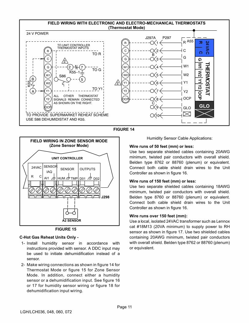
FIGURE 14
FIELD WIRING WITH ELECTRONIC AND ELECTRO-MECHANICAL THERMOSTATS(Thermostat Mode)
J262
C
10
11
12
P297J297A1
2B
3
4
5
6
7
8C
9
10
24 V POWER
W1
W2
P26
2
A55R
OCP
C
G
W1
W2
Y1
Y2
2
K55
B
A
K55−17
5
2
S86
R
OCP
C
G
W1
W2
Y1
Y2
TO R
TO G
TO Y1
TO PROVIDE SUPERMARKET REHEAT SCHEMEUSE S86 DEHUMIDISTAT AND K55.
ALL OTHER THERMOSTATSIGNALS REMAIN CONNECTEDAS SHOWN ON THE RIGHT.
TO UNIT CONTROLLER
2
THERMOSTAT INPUTS
FIGURE 15
FIELD WIRING IN ZONE SENSOR MODE(Zone Sensor Mode)
A2 SENSOR
OUTPUTSSENSOR
SENSOR24VAC
R C
IAQ
HUMAI1 D01TMP D02
UNIT CONTROLLER
J298
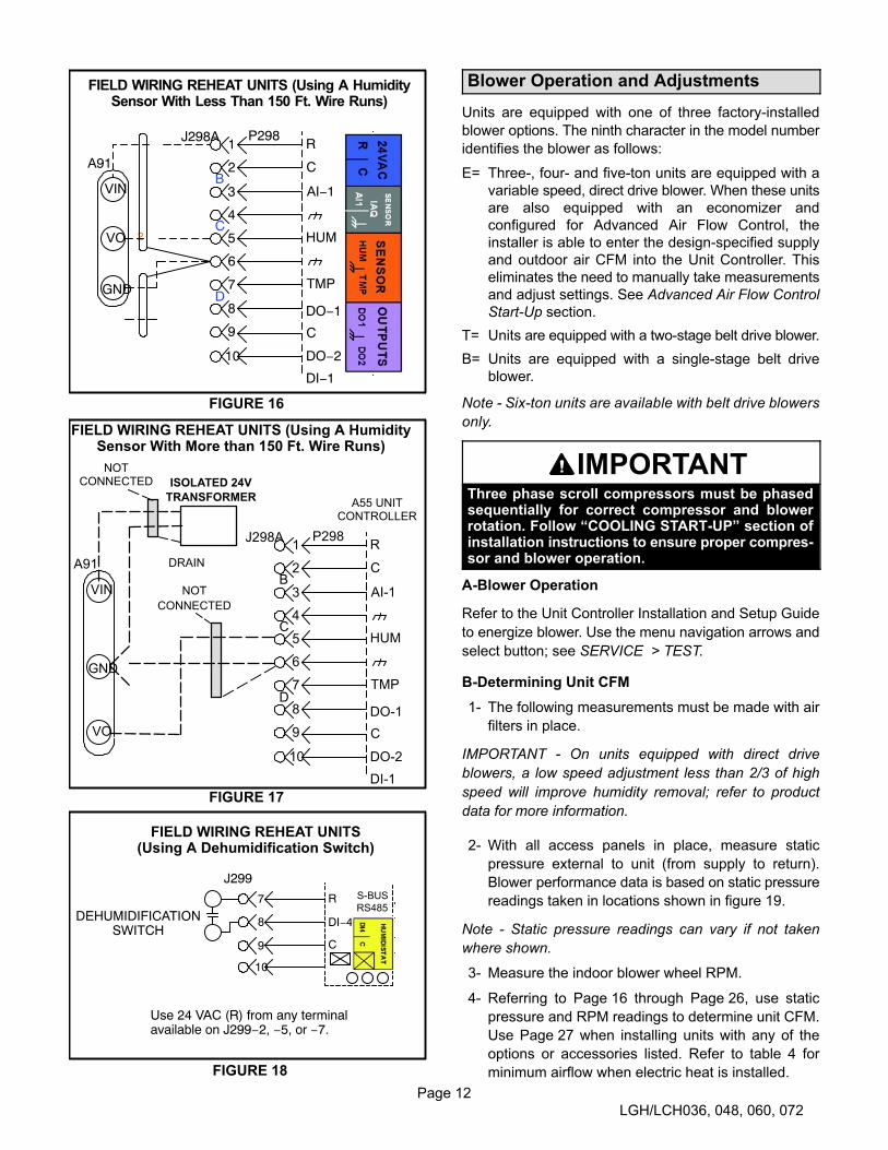
C-Hot Gas Reheat Units Only -
1- Install humidity sensor in accordance with
instructions provided with sensor. A DDC input may
be used to initiate dehumidification instead of a
sensor.
2- Make wiring connections as shown in figure 14 for
Thermostat Mode or figure 15 for Zone Sensor
Mode. In addition, connect either a humidity
sensor or a dehumidification input. See figure 16
or 17 for humidity sensor wiring or figure 18 for
dehumidification input wiring.
Humidity Sensor Cable Applications:
Wire runs of 50 feet (mm) or less:
Use two separate shielded cables containing 20AWG
minimum, twisted pair conductors with overall shield.
Belden type 8762 or 88760 (plenum) or equivalent.
Connect both cable shield drain wires to the Unit
Controller as shown in figure 16.
Wire runs of 150 feet (mm) or less:
Use two separate shielded cables containing 18AWG
minimum, twisted pair conductors with overall shield.
Belden type 8760 or 88760 (plenum) or equivalent.
Connect both cable shield drain wires to the Unit
Controller as shown in figure 16.
Wire runs over 150 feet (mm):
Use a local, isolated 24VAC transformer such as Lennox
cat #18M13 (20VA minimum) to supply power to RH
sensor as shown in figure 17. Use two shielded cables
containing 20AWG minimum, twisted pair conductors
with overall shield. Belden type 8762 or 88760 (plenum)
or equivalent.
Page 12
LGH/LCH036, 048, 060, 072
FIGURE 16
FIELD WIRING REHEAT UNITS (Using A HumiditySensor With Less Than 150 Ft. Wire Runs)
9
8
10
11
122
J262
B
5
P298J298A
6
1
2B
3
4C
5
6
7D
10
A91
VIN
VO
GND
P26
2
R
C
AI−1
HUM
TMP
DO−1
C
DI−1
DO−2
FIGURE 17
FIELD WIRING REHEAT UNITS (Using A HumiditySensor With More than 150 Ft. Wire Runs)
ISOLATED 24V
TRANSFORMER
9
8
P298J298A1
2B
3
4C
5
6
7D
10
A91
VIN
VO
GND
R
C
AI-1
HUM
TMP
DO-1
C
DI-1
DO-2
NOT
CONNECTED
NOTCONNECTED
DRAIN
A55 UNITCONTROLLER
FIGURE 18
FIELD WIRING REHEAT UNITS(Using A Dehumidification Switch)
7
10
8
9
R
DI−4
C
Use 24 VAC (R) from any terminalavailable on J299−2, −5, or −7.
J299
DEHUMIDIFICATIONSWITCH
Blower Operation and Adjustments
Units are equipped with one of three factory-installed
blower options. The ninth character in the model number
identifies the blower as follows:
E= Three-, four- and five-ton units are equipped with a
variable speed, direct drive blower. When these units
are also equipped with an economizer and
configured for Advanced Air Flow Control, the
installer is able to enter the design-specified supply
and outdoor air CFM into the Unit Controller. This
eliminates the need to manually take measurements
and adjust settings. See Advanced Air Flow Control
Start-Up section.
T= Units are equipped with a two-stage belt drive blower.
B= Units are equipped with a single-stage belt drive
blower.
Note - Six-ton units are available with belt drive blowers
only.
IMPORTANTThree phase scroll compressors must be phasedsequentially for correct compressor and blowerrotation. Follow “COOLING START-UP” section ofinstallation instructions to ensure proper compressor and blower operation.
A-Blower Operation
Refer to the Unit Controller Installation and Setup Guide
to energize blower. Use the menu navigation arrows and
select button; see SERVICE > TEST.
B-Determining Unit CFM
1- The following measurements must be made with air
filters in place.
IMPORTANT - On units equipped with direct drive
blowers, a low speed adjustment less than 2/3 of high
speed will improve humidity removal; refer to product
data for more information.
2- With all access panels in place, measure static
pressure external to unit (from supply to return).
Blower performance data is based on static pressure
readings taken in locations shown in figure 19.
Note - Static pressure readings can vary if not taken
where shown.
3- Measure the indoor blower wheel RPM.
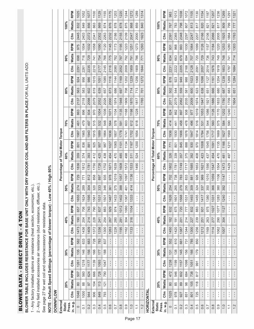
4- Referring to Page 16 through Page 26, use static
pressure and RPM readings to determine unit CFM.
Use Page 27 when installing units with any of the
options or accessories listed. Refer to table 4 for
minimum airflow when electric heat is installed.

Page 13
LGH/LCH036, 048, 060, 072
FIGURE 19
LOCATION OF STATIC PRESSURE READINGS
SUPPLY AIRREADINGLOCATION
SUPPLYRE
TURN
INSTALLATIONS WITH DUCTWORK
SUPPLY RETURN
INSTALLATIONS WITH CEILING DIFFUSERS
MAINDUCT RUN
FIRST BRANCHOFF OF MAIN RUN
DIFFUSER
ROOFTOP UNIT ROOFTOP UNIT
SUPPLY AIRREADINGLOCATION
RETURN AIRREADING LOCATION
RETURN AIRREADINGLOCATION
TABLE 3036, 048, 060 DIRECT DRIVE PARAMETER SETTINGS
ParameterLGH/LCH Unit Factory Default Settings
Field Setting Description036 H4E 048 H4E 060 H4E 036-060 S4T
SETUP > TEST & BALANCE > BLOWER
HIGH SPEED 55% 30% 59% Not ApplicablePercentage torque forindoor blower high speed.
LOW SPEED 28% 40% 36% Not ApplicablePercentage torque forindoor blower low speed.
SETUP > TEST & BALANCE > DAMPER
BLOWER ON HIGH 10% 10 % 10 % 10 %Minimum damper positionduring high speed bloweroperation.
BLOWER ON LOW 15 % 15 % 15 % Not ApplicableMinimum damper positionduring low speed blower operation.
SETTINGS > RTU OPTIONS > EDIT PARAMETER = 6
BLOWER SMOKE OUTPUT
55% 80% 59% Not ApplicablePercentage torque forindoor blower smokespeed.
Installer: Circle applicable unit model number and record any parameter changes under “Field Setting” column. Settings need to be recorded by
installer for use when Unit Controller is replaced or reprogrammed.
TABLE 4MINIMUM AIRFLOW-LC UNITS WITH ELECTRIC HEAT
(BELT DRIVE)
KwCFM
Downflow & Horizontal Airflow
LCH036HE 1080
LCH048HE 1280
LCH060HE 1600
C-Adjusting Unit CFM - Direct Drive Blowers
The supply CFM can be adjusted by changing Unit
Controller settings. Refer to table 3. Adjustments can also
be made by using optional software. Record any CFM
changes on the parameter settings label located on the
inside of the compressor access panel.
Note - To adjust CFM on units configured for optional
“Advanced Air Flow Control”, refer to Advanced Air Flow
Control Start-Up section.
D-Adjusting Unit CFM - Belt Drive Blowers
The blower RPM can be adjusted at the motor pulley.
Loosen Allen screw and turn adjustable pulley clockwise
to increase CFM. Turn counterclockwise to decrease
CFM. See figure 20. Do not exceed minimum and
maximum number of pulley turns as shown in table 5.
TABLE 5MINIMUM AND MAXIMUM PULLEY ADJUSTMENT
Belt Min. Turns Open Maxi. Turns Open
A Section No minimum 5

Page 14
LGH/LCH036, 048, 060, 072
BLOWER ASSEMBLY
TO INCREASE BELT TENSION
1-Loosen four bolts securing motor base to mountingframe.
2-Slide the motor downward to tighten the belt.
3-Tighten four bolts on motor base.
TO INCREASE CFMLOOSEN ALLEN SCREW &
TURN PULLEY CLOCKWISE
TO DECREASE CFMTURN PULLEY
COUNTERCLOCKWISE
FIGURE 20
PULLEY
MOTOR
SIDE VIEW
ALLENSCREW
LOOSEN FOUR BOLTS ANDSLIDE BLOWER MOTOR
DOWNWARD TO TIGHTEN BELT
LOOSEN ALLENSCREW TO
ADJUST CFM
E-Blower Belt Adjustment - Belt Drive
Maximum life and wear can be obtained from belts only
if proper pulley alignment and belt tension are
maintained. Tension new belts after a 24-48 hour
period of operation. This will allow belt to stretch and
seat grooves. Make sure blower and motor pulley are
aligned as shown in figure 21.
FIGURE 21
PULLEY ALIGNMENT
BELT BLOWERPULLEY
MOTORPULLEY
NOT ALIGNED
ALIGNED
1- Loosen four bolts securing motor base to mounting
frame. See figure 20.
2- To increase belt tension -
Slide blower motor downward to tighten the belt. This
increases the distance between the blower motor and
the blower housing.
3- To loosen belt tension -
Slide blower motor upward to loosen the belt. This
decreases the distance between the blower motor
and the blower housing.
4- Tighten four bolts securing motor base to the
mounting frame.
F-Blower Belt Adjustment - Units Equipped With An
Optional Belt Tensioner
1- Remove blower belt.
2- Remove bracket from blower housing. See figure 23.
3- Remove the screw from the back side of the bracket.
4- Move the tensioner to the appropriate adjustment
hole and reinstall screw.
5- Replace bracket.
6- Replace blower belt. See figure 24.
G-Check Belt Tension
Overtensioning belts shortens belt and bearing life.
Check belt tension as follows:
1- Measure span length X. See figure 22.
MEASURE BELT TENSION
FIGURE 22
DEFLECTION 1/64” PER INCH OF SPANOR 1.5mm PER 100mm OF SPAN
FORCE
2- Apply perpendicular force to center of span (X) with
enough pressure to deflect belt 1/64” for every inch
of span length or 1.5mm per 100mm of span length.

Page 15
LGH/LCH036, 048, 060, 072
Example: Deflection distance of a 40” span would be
40/64” or 5/8”.
Example: Deflection distance of a 400mm span
would be 6mm.
3- Measure belt deflection force. For a used belt, the
deflection force should be 5 lbs. (35kPa). A new belt
deflection force should be 7 lbs. (48kPa).
A force below these values indicates an
undertensioned belt. A force above these values
indicates an overtensioned belt.
H-Field-Furnished Blower Drives
For field-furnished blower drives, use page 19 through 26
to determine BHP and RPM required. Reference Page 27
to determine the drive kit number. Reference table 6 for
manufacturer's drive numbers.
FIGURE 23
ADJUST BELT TENSIONER
MAXIMUM
TENSION
MINIMUM
TENSION
INDICATOR SHOULD BE
BETWEEN MINIMUM AND
MAXIMUM TENSION LINES
FACTORY-SET
POSITION
TIGHTER
BELT
POSITION
TENSIONER
TIGHTEST
BELT
POSITION
BRACKET
TIGHTEN MOUNTING
BOLT TO 22 LB./FT.
USING 9/16” WRENCH
INSTALL BELT
FIGURE 24
1
2
3
4
TENSIONERDRIVER
PULLEY
DRIVEN
PULLEY
ROTATE DRIVEN
PULLEY TO SEAT BELT

Page 16
BLO
WE
R D
ATA
- D
IRE
CT
DR
IVE
- 3
TO
NB
LOW
ER T
AB
LE IN
CLU
DES
RES
ISTA
NC
E FO
R B
ASE
UN
IT O
NLY
WIT
H D
RY IN
DO
OR
CO
IL A
ND
AIR
FIL
TER
S IN
PLA
CE.
FOR
ALL
UN
ITS
AD
D:
1 - A
ny fa
ctor
y in
stal
led
optio
ns a
ir re
sist
ance
(hea
t sec
tion,
eco
nom
izer
, etc
.).2
- Any
fiel
d in
stal
led
acce
ssor
ies
air r
esis
tanc
e (d
uct r
esis
tanc
e, d
iffus
er, e
tc.).
See
pag
e 27
for w
et c
oil a
nd o
ptio
ns/a
cces
sory
air
resi
stan
ce d
ata.
NO
TE -
Def
ault
Spee
d Se
tting
s (p
erce
ntag
e of
blo
wer
torq
ue) -
Low
28%
/ H
igh
55%
DO
WN
FLO
WEx
tern
al
Stat
ic
Pres
s.
in. w
.g.
Perc
enta
ge o
f Tot
al M
otor
Tor
que
20%
30%
40%
50%
60%
70%
80%
90%
100%
Cfm
Wat
tsR
PMC
fmW
atts
RPM
Cfm
Wat
tsR
PMC
fmW
atts
RPM
Cfm
Wat
tsR
PMC
fmW
atts
RPM
Cfm
Wat
tsR
PMC
fmW
atts
RPM
Cfm
Wat
tsR
PM0
796
3940
797
569
451
1154
9849
412
9814
056
714
4218
163
915
7023
669
216
9729
274
418
0735
778
519
1742
282
50.
171
944
482
915
7652
311
1010
856
412
5715
162
614
0419
368
715
3724
873
316
7030
477
917
8436
981
518
9843
385
00.
266
349
538
864
8358
510
6411
763
312
2016
067
913
7520
372
515
0825
977
016
4131
681
517
5438
485
318
6645
289
10.
359
355
607
806
9165
110
1812
669
511
7417
173
713
3021
678
014
7127
281
516
1232
885
017
2439
889
018
3546
993
00.
452
760
665
749
9770
897
113
575
111
3618
078
313
0022
581
514
3528
585
815
6934
490
016
8941
393
018
0948
195
90.
546
065
722
692
104
761
924
143
801
1090
190
833
1256
238
866
1398
296
899
1540
355
932
1662
424
960
1784
493
988
0.6
- - -
- - -
- - -
- - -
- - -
- - -
855
154
864
1033
202
889
1211
250
914
1361
308
939
1511
365
963
1629
437
995
1746
508
1028
0.7
- - -
- - -
- - -
- - -
- - -
- - -
808
161
898
995
209
922
1181
258
946
1325
319
976
1468
379
1007
1588
450
1036
1708
522
1065
0.8
- - -
- - -
- - -
- - -
- - -
- - -
743
170
942
940
220
966
1137
269
991
1281
331
1020
1425
392
1049
1548
463
1074
1670
533
1100
0.9
- - -
- - -
- - -
- - -
- - -
- - -
676
178
979
884
229
1006
1092
280
1033
1237
342
1061
1381
404
1088
1513
472
1105
1645
539
1121
1.0
- - -
- - -
- - -
- - -
- - -
- - -
605
187
1011
819
240
1049
1032
294
1087
1192
353
1100
1352
411
1112
1474
480
1137
1595
549
1161
1.1
- - -
- - -
- - -
- - -
- - -
- - -
- - -
- - -
- - -
- - -
- - -
- - -
988
304
1124
1142
364
1141
1295
424
1158
1420
490
1177
1544
555
1195
1.2
- - -
- - -
- - -
- - -
- - -
- - -
- - -
- - -
- - -
- - -
- - -
- - -
- - -
- - -
- - -
- - -
- - -
- - -
1251
433
1189
1373
495
1207
1494
558
1225
HO
RIZ
ON
TAL
Exte
rnal
St
atic
Pr
ess.
in
. w.g
.
Perc
enta
ge o
f Tot
al M
otor
Tor
que
20%
30%
40%
50%
60%
70%
80%
90%
100%
Cfm
Wat
tsR
PMC
fmW
atts
RPM
Cfm
Wat
tsR
PMC
fmW
atts
RPM
Cfm
Wat
tsR
PMC
fmW
atts
RPM
Cfm
Wat
tsR
PMC
fmW
atts
RPM
Cfm
Wat
tsR
PM0
807
4437
298
265
431
1157
8649
012
9912
654
614
4116
760
215
6521
464
716
8826
269
217
9532
873
419
0139
377
60.
170
850
468
906
7751
311
0310
455
912
4714
361
213
9118
366
615
2223
170
416
5228
074
217
6634
677
918
7941
381
50.
263
456
541
841
8858
310
4812
062
512
0615
666
313
6319
270
114
9124
374
216
1929
478
317
3136
182
018
4342
985
70.
352
363
648
759
9866
999
413
469
011
5017
172
913
0620
976
914
4625
879
615
8530
782
316
9637
686
018
0744
489
60.
443
769
732
688
107
742
939
146
752
1101
183
785
1263
221
818
1399
273
849
1535
326
881
1653
392
908
1771
458
935
0.5
344
7582
361
511
681
788
515
681
210
5319
483
812
2023
286
513
6128
589
215
0233
991
816
1440
694
917
2547
398
00.
6- -
-- -
-- -
-- -
-- -
-- -
-81
716
788
399
020
790
511
6224
692
713
0730
194
914
5135
697
115
7042
099
316
8948
410
140.
7- -
-- -
-- -
-- -
-- -
-- -
-76
217
493
894
121
595
411
1925
697
112
6931
298
814
1836
710
0515
3643
010
2616
5349
410
470.
8- -
-- -
-- -
-- -
-- -
-- -
-70
817
899
189
222
210
0210
7626
610
1312
2232
410
3413
6838
310
5414
8444
410
7315
9950
610
920.
9- -
-- -
-- -
-- -
-- -
-- -
-64
518
210
5083
223
010
5910
1927
710
6811
6833
710
8413
1739
711
0014
3145
611
1715
4551
611
341.
0- -
-- -
-- -
-- -
-- -
-- -
-58
418
411
0578
023
511
0697
628
511
0711
2234
811
2512
6741
111
4413
7946
711
5814
9152
211
721.
1- -
-- -
-- -
-- -
-- -
-- -
-- -
-- -
-- -
-- -
-- -
-- -
-92
329
511
5510
7035
911
6912
1742
311
8413
2747
511
9514
3652
612
071.
2- -
-- -
-- -
-- -
-- -
-- -
-- -
-- -
-- -
-- -
-- -
-- -
-- -
-- -
-- -
-- -
-- -
-- -
-11
6643
412
2212
6548
112
3413
6452
712
46
Page 17
BLO
WE
R D
ATA
- D
IRE
CT
DR
IVE
- 4
TO
NB
LOW
ER T
AB
LE IN
CLU
DES
RES
ISTA
NC
E FO
R B
ASE
UN
IT O
NLY
WIT
H D
RY IN
DO
OR
CO
IL A
ND
AIR
FIL
TER
S IN
PLA
CE.
FOR
ALL
UN
ITS
AD
D:
1 - A
ny fa
ctor
y in
stal
led
optio
ns a
ir re
sist
ance
(hea
t sec
tion,
eco
nom
izer
, etc
.).2
- Any
fiel
d in
stal
led
acce
ssor
ies
air r
esis
tanc
e (d
uct r
esis
tanc
e, d
iffus
er, e
tc.).
See
pag
e 27
for w
et c
oil a
nd o
ptio
ns/a
cces
sory
air
resi
stan
ce d
ata.
NO
TE -
Def
ault
Spee
d Se
tting
s (p
erce
ntag
e of
blo
wer
torq
ue) -
Low
40%
/ H
igh
80%
DO
WN
FLO
WEx
tern
al
Stat
ic
Pres
s.
in. w
.g.
Perc
enta
ge o
f Tot
al M
otor
Tor
que
20%
30%
40%
50%
60%
70%
80%
90%
100%
Cfm
Wat
tsR
PMC
fmW
atts
RPM
Cfm
Wat
tsR
PMC
fmW
atts
RPM
Cfm
Wat
tsR
PMC
fmW
atts
RPM
Cfm
Wat
tsR
PMC
fmW
atts
RPM
Cfm
Wat
tsR
PM
010
4880
507
1261
135
582
1473
190
657
1655
274
729
1836
359
801
1987
461
863
2137
563
924
2291
698
975
2445
832
1025
0.1
1000
8856
012
1814
663
314
3620
470
616
2428
977
118
1237
483
619
6547
989
621
1858
395
622
6171
610
0424
0384
910
520.
294
497
624
1177
156
683
1409
214
743
1595
304
812
1781
393
881
1940
497
934
2098
602
986
2235
729
1032
2372
856
1077
0.3
906
104
666
1139
166
728
1372
228
790
1561
320
858
1750
412
925
1915
515
970
2079
619
1015
2210
741
1058
2341
863
1100
0.4
849
113
728
1093
177
783
1336
241
837
1531
333
897
1726
425
957
1889
532
1004
2052
639
1051
2177
754
1090
2302
869
1129
0.5
793
121
790
1047
188
837
1300
254
883
1501
346
935
1702
438
987
1864
548
1036
2026
657
1085
2145
766
1120
2263
874
1155
0.6
- - -
- - -
- - -
- - -
- - -
- - -
1263
267
929
1467
361
978
1671
454
1027
1836
564
1071
2000
673
1116
2116
775
1145
2232
876
1175
0.7
- - -
- - -
- - -
- - -
- - -
- - -
1226
280
974
1433
375
1019
1639
470
1065
1807
578
1104
1974
686
1144
2080
782
1173
2186
878
1203
0.8
- - -
- - -
- - -
- - -
- - -
- - -
1195
291
1012
1402
388
1057
1608
485
1101
1778
591
1135
1948
697
1169
2052
787
1195
2155
878
1220
0.9
- - -
- - -
- - -
- - -
- - -
- - -
1162
304
1060
1367
401
1097
1572
498
1134
1741
603
1168
1909
708
1202
2009
792
1223
2109
875
1244
1.0
- - -
- - -
- - -
- - -
- - -
- - -
1133
316
1104
1333
414
1136
1533
511
1167
1702
612
1198
1870
714
1229
1959
791
1251
2047
868
1272
1.1
- - -
- - -
- - -
- - -
- - -
- - -
- - -
- - -
- - -
- - -
- - -
- - -
1490
524
1200
1654
618
1228
1817
713
1256
1909
786
1273
2000
859
1289
1.2
- - -
- - -
- - -
- - -
- - -
- - -
- - -
- - -
- - -
- - -
- - -
- - -
- - -
- - -
- - -
- - -
- - -
- - -
1765
701
1272
1844
771
1293
1923
840
1314
HO
RIZ
ON
TAL
Exte
rnal
St
atic
Pr
ess.
in
. w.g
.
Perc
enta
ge o
f Tot
al M
otor
Tor
que
20%
30%
40%
50%
60%
70%
80%
90%
100%
Cfm
Wat
tsR
PMC
fmW
atts
RPM
Cfm
Wat
tsR
PMC
fmW
atts
RPM
Cfm
Wat
tsR
PMC
fmW
atts
RPM
Cfm
Wat
tsR
PMC
fmW
atts
RPM
Cfm
Wat
tsR
PM
010
2580
472
1238
131
552
1450
182
632
1626
254
702
1802
326
771
1936
414
824
2071
502
878
2231
634
931
2391
767
983
0.1
978
8554
611
9913
861
014
2019
167
516
0126
573
817
8133
980
119
3044
186
220
7954
492
322
2266
396
823
6578
310
130.
292
789
602
1157
145
661
1387
201
720
1568
279
783
1749
357
845
1906
458
897
2062
559
949
2205
679
993
2348
798
1038
0.3
851
9868
410
9815
673
113
4421
477
715
3129
583
317
1737
588
818
7647
893
820
3558
198
821
6669
410
3022
9780
710
720.
480
110
573
810
5116
678
513
0022
783
214
9330
988
116
8539
293
018
4749
697
720
0960
010
2321
2870
710
6422
4781
311
050.
572
511
881
799
117
985
012
5623
988
314
5532
492
616
5340
897
018
1451
610
1919
7462
310
6820
9172
010
9922
0781
711
300.
6- -
-- -
-- -
-- -
-- -
-- -
-12
1225
193
114
1733
796
916
2142
310
0817
8453
110
5319
4763
810
9820
5772
911
2621
6682
011
540.
7- -
-- -
-- -
-- -
-- -
-- -
-11
6926
397
513
8035
010
1015
9043
710
4517
5654
410
8619
2165
111
2720
1473
611
5721
0682
111
870.
8- -
-- -
-- -
-- -
-- -
-- -
-11
1427
710
2713
3136
610
5915
4745
410
9117
1756
011
2618
8666
611
6119
7674
311
8420
6682
112
070.
9- -
-- -
-- -
-- -
-- -
-- -
-10
6229
010
7712
8338
011
0615
0447
011
3516
6957
511
7018
3368
012
0419
1974
912
2020
0581
712
361.
0- -
-- -
-- -
-- -
-- -
-- -
-10
0730
411
2712
4039
211
4714
7348
111
6616
2758
412
0217
8068
712
3818
5374
812
5319
2580
912
691.
1- -
-- -
-- -
-- -
-- -
-- -
-- -
-- -
-- -
-- -
-- -
-- -
-14
2949
712
1115
6959
012
4017
0968
312
6917
8774
112
8018
6479
912
911.
2- -
-- -
-- -
-- -
-- -
-- -
-- -
-- -
-- -
-- -
-- -
-- -
-- -
-- -
-- -
-- -
-- -
-- -
-16
0465
112
8416
8471
413
0317
6377
713
21

Page 18
BLO
WE
R D
ATA
- D
IRE
CT
DR
IVE
- 5
TO
NB
LOW
ER T
AB
LE IN
CLU
DES
RES
ISTA
NC
E FO
R B
ASE
UN
IT O
NLY
WIT
H D
RY IN
DO
OR
CO
IL A
ND
AIR
FIL
TER
S IN
PLA
CE.
FOR
ALL
UN
ITS
AD
D:
1 - A
ny fa
ctor
y in
stal
led
optio
ns a
ir re
sist
ance
(hea
t sec
tion,
eco
nom
izer
, etc
.).2
- Any
fiel
d in
stal
led
acce
ssor
ies
air r
esis
tanc
e (d
uct r
esis
tanc
e, d
iffus
er, e
tc.).
See
pag
e 27
for w
et c
oil a
nd o
ptio
ns/a
cces
sory
air
resi
stan
ce d
ata.
NO
TE -
Def
ault
Spee
d Se
tting
s (p
erce
ntag
e of
blo
wer
torq
ue) -
Low
36%
/ H
igh
59%
DO
WN
FLO
WEx
tern
al
Stat
ic
Pres
s.
in. w
.g.
Perc
enta
ge o
f Tot
al M
otor
Tor
que
20%
30%
40%
50%
60%
70%
80%
90%
100%
Cfm
Wat
tsR
PMC
fmW
atts
RPM
Cfm
Wat
tsR
PMC
fmW
atts
RPM
Cfm
Wat
tsR
PMC
fmW
atts
RPM
Cfm
Wat
tsR
PMC
fmW
atts
RPM
Cfm
Wat
tsR
PM
011
3279
438
1353
146
524
1575
212
610
1765
300
670
1954
388
730
2126
513
796
2298
638
861
2445
792
913
2591
946
965
0.1
1061
8649
413
0515
556
815
4822
364
117
4331
570
219
3740
776
421
1053
182
322
8265
488
324
2680
893
525
7096
398
70.
299
094
550
1253
165
614
1516
236
678
1716
330
735
1916
423
793
2088
549
851
2260
675
910
2405
827
959
2549
979
1009
0.3
920
102
606
1202
175
659
1484
248
713
1687
345
770
1890
442
828
2065
568
882
2239
694
937
2384
844
983
2528
994
1030
0.4
849
111
662
1151
185
705
1452
260
747
1658
360
804
1863
460
861
2041
586
911
2218
713
962
2363
861
1006
2508
1009
1050
0.5
779
121
718
1094
198
754
1410
275
790
1626
374
838
1842
473
886
2020
601
936
2197
730
987
2342
876
1028
2487
1023
1070
0.6
- - -
- - -
- - -
- - -
- - -
- - -
1368
289
830
1589
390
876
1810
492
921
1993
619
966
2176
746
1010
2316
895
1054
2456
1043
1099
0.7
- - -
- - -
- - -
- - -
- - -
- - -
1325
303
868
1552
406
911
1778
509
954
1966
635
993
2154
761
1033
2295
908
1075
2435
1055
1117
0.8
- - -
- - -
- - -
- - -
- - -
- - -
1261
321
920
1504
423
952
1746
524
984
1934
653
1024
2122
782
1064
2268
925
1100
2414
1067
1135
0.9
- - -
- - -
- - -
- - -
- - -
- - -
1211
337
964
1462
437
988
1714
538
1012
1902
669
1053
2090
801
1094
2237
942
1127
2383
1084
1161
1.0
- - -
- - -
- - -
- - -
- - -
- - -
1151
354
1013
1412
454
1029
1672
553
1045
1871
682
1078
2069
811
1112
2211
955
1149
2352
1099
1185
1.1
- - -
- - -
- - -
- - -
- - -
- - -
- - -
- - -
- - -
- - -
- - -
- - -
1629
566
1073
1828
698
1109
2027
830
1146
2174
971
1177
2321
1112
1208
1.2
- - -
- - -
- - -
- - -
- - -
- - -
- - -
- - -
- - -
- - -
- - -
- - -
- - -
- - -
- - -
- - -
- - -
- - -
1984
844
1175
2137
984
1202
2290
1124
1230
HO
RIZ
ON
TAL
Exte
rnal
St
atic
Pr
ess.
in
. w.g
.
Perc
enta
ge o
f Tot
al M
otor
Tor
que
20%
30%
40%
50%
60%
70%
80%
90%
100%
Cfm
Wat
tsR
PMC
fmW
atts
RPM
Cfm
Wat
tsR
PMC
fmW
atts
RPM
Cfm
Wat
tsR
PMC
fmW
atts
RPM
Cfm
Wat
tsR
PMC
fmW
atts
RPM
Cfm
Wat
tsR
PM
011
2782
426
1367
141
504
1607
200
582
1806
296
644
2005
391
706
2167
495
764
2328
599
822
2463
749
872
2598
899
922
0.1
1071
8647
613
2614
854
315
8021
061
017
8131
167
519
8141
174
021
4551
679
523
0962
084
924
5677
589
826
0293
194
70.
210
1091
529
1268
160
598
1525
229
668
1735
332
724
1945
434
781
2117
537
828
2289
640
875
2438
795
921
2587
949
967
0.3
930
100
597
1214
169
647
1497
239
696
1707
345
755
1917
452
814
2093
556
857
2269
660
900
2417
817
948
2565
975
995
0.4
869
109
646
1156
184
699
1442
258
751
1665
364
798
1888
469
845
2066
577
889
2243
685
933
2393
842
978
2543
998
1022
0.5
813
119
689
1114
193
734
1414
267
778
1637
376
827
1860
485
876
2039
597
920
2217
709
963
2373
861
1002
2528
1013
1040
0.6
- - -
- - -
- - -
- - -
- - -
- - -
1358
286
831
1595
394
868
1832
501
905
2012
616
949
2191
731
993
2349
882
1028
2506
1033
1064
0.7
- - -
- - -
- - -
- - -
- - -
- - -
1330
296
857
1560
409
903
1789
523
949
1977
638
985
2164
753
1020
2324
902
1054
2484
1052
1088
0.8
- - -
- - -
- - -
- - -
- - -
- - -
1275
315
908
1518
426
942
1761
536
977
1950
655
1011
2138
773
1046
2296
923
1081
2454
1073
1116
0.9
- - -
- - -
- - -
- - -
- - -
- - -
1233
329
946
1483
439
975
1732
549
1004
1922
670
1037
2112
792
1071
2272
939
1104
2432
1087
1136
1.0
- - -
- - -
- - -
- - -
- - -
- - -
1192
343
982
1441
455
1012
1690
567
1043
1881
692
1074
2072
818
1105
2237
960
1133
2402
1102
1161
1.1
- - -
- - -
- - -
- - -
- - -
- - -
- - -
- - -
- - -
- - -
- - -
- - -
1662
578
1068
1854
706
1097
2046
833
1126
2206
975
1157
2365
1117
1188
1.2
- - -
- - -
- - -
- - -
- - -
- - -
- - -
- - -
- - -
- - -
- - -
- - -
- - -
- - -
- - -
- - -
- - -
- - -
1994
861
1163
2165
993
1185
2336
1125
1206

Page 19
BLOWER DATA - BELT DRIVE - 3 TONBLOWER TABLE INCLUDES RESISTANCE FOR BASE UNIT ONLY WITH DRY INDOOR COIL AND AIR FILTERS IN PLACE. FOR ALL UNITS ADD: 1 - Any factory installed options air resistance (heat section, economizer, etc.). 2 - Any field installed accessories air resistance (duct resistance, diffuser, etc.).See page 27 for blower motors and drives and wet coil and options/accessory air resistance data.
DOWNFLOW
Air Volume (cfm)
External Static (in.w.g.)
0.10 0.20 0.30 0.40 0.50 0.60 0.70 0.80 0.9 1.0
RPM BHP RPM BHP RPM BHP RPM BHP RPM BHP RPM BHP RPM BHP RPM BHP RPM BHP RPM BHP
700 453 0.07 523 0.11 596 0.14 679 0.17 762 0.18 828 0.21 878 0.24 927 0.26 979 0.29 1029 0.31
800 471 0.09 542 0.13 614 0.16 696 0.19 777 0.21 841 0.23 889 0.26 938 0.29 990 0.31 1042 0.34
900 493 0.11 563 0.15 634 0.19 715 0.21 793 0.23 854 0.26 902 0.29 950 0.32 1002 0.34 1054 0.36
1000 517 0.14 587 0.18 657 0.21 736 0.24 811 0.26 869 0.29 916 0.32 964 0.35 1015 0.37 1067 0.4
1100 544 0.17 613 0.21 683 0.24 759 0.27 831 0.3 886 0.32 931 0.36 978 0.38 1028 0.41 1078 0.43
1200 574 0.2 643 0.24 711 0.27 784 0.3 852 0.33 904 0.36 947 0.39 993 0.42 1042 0.45 1091 0.47
1300 608 0.24 676 0.28 743 0.31 812 0.34 875 0.37 923 0.4 964 0.44 1010 0.46 1057 0.49 1104 0.51
1400 645 0.28 711 0.31 776 0.35 842 0.38 898 0.41 942 0.44 983 0.48 1028 0.51 1074 0.53 1120 0.56
Air Volume (cfm)
External Static (in.w.g.)
1.1 1.2 1.3 1.4 1.5 1.6 1.7 1.8 1.9 2.0
RPM BHP RPM BHP RPM BHP RPM BHP RPM BHP RPM BHP RPM BHP RPM BHP RPM BHP RPM BHP
700 1078 0.33 1124 0.36 - - - - - - - - - - - - - - - - - - - - - - - - - - - - - - - - - - - - - - - - - - - - - - - -
800 1091 0.36 1137 0.39 1180 0.41 1221 0.44 1260 0.47 - - - - - - - - - - - - - - - - - - - - - - - - - - - - - -
900 1105 0.39 1150 0.42 1192 0.45 1232 0.47 1270 0.5 1307 0.53 1345 0.56 1382 0.59 1420 0.62 - - - - - -
1000 1117 0.42 1162 0.45 1203 0.48 1242 0.51 1279 0.54 1316 0.57 1353 0.6 1390 0.63 1427 0.66 1465 0.7
1100 1126 0.46 1171 0.49 1212 0.52 1251 0.56 1288 0.59 1325 0.62 1361 0.65 1397 0.68 1433 0.71 1470 0.75
1200 1137 0.5 1180 0.54 1222 0.57 1260 0.6 1298 0.64 1334 0.67 1369 0.7 1404 0.73 1440 0.77 1477 0.8
1300 1149 0.55 1191 0.58 1232 0.62 1270 0.65 1307 0.69 1343 0.72 1378 0.76 1413 0.79 1449 0.82 1486 0.86
1400 1163 0.6 1204 0.63 1243 0.67 1281 0.71 1317 0.74 1353 0.78 1388 0.82 1423 0.85 1459 0.89 1496 0.92

Page 20
BLOWER DATA - BELT DRIVE - 3 TONBLOWER TABLE INCLUDES RESISTANCE FOR BASE UNIT ONLY WITH DRY INDOOR COIL AND AIR FILTERS IN PLACE. FOR ALL UNITS ADD: 1 - Any factory installed options air resistance (heat section, economizer, etc.). 2 - Any field installed accessories air resistance (duct resistance, diffuser, etc.).See page 27 for blower motors and drives and wet coil and options/accessory air resistance data.
HORIZONTAL
Air Volume (cfm)
External Static (in.w.g.)
0.10 0.20 0.30 0.40 0.50 0.60 0.70 0.80 0.9 1.0
RPM BHP RPM BHP RPM BHP RPM BHP RPM BHP RPM BHP RPM BHP RPM BHP RPM BHP RPM BHP
700 440 0.07 510 0.1 585 0.12 657 0.14 726 0.17 793 0.2 856 0.23 915 0.25 967 0.28 1016 0.31
800 456 0.08 526 0.11 600 0.14 672 0.16 739 0.19 804 0.22 866 0.25 923 0.28 975 0.31 1025 0.34
900 474 0.1 544 0.13 617 0.16 688 0.18 754 0.21 818 0.24 877 0.27 932 0.3 984 0.33 1034 0.36
1000 495 0.12 565 0.15 637 0.18 707 0.21 771 0.23 832 0.27 889 0.3 943 0.33 993 0.36 1043 0.39
1100 518 0.14 588 0.18 659 0.21 727 0.23 789 0.26 848 0.3 903 0.33 954 0.37 1003 0.4 1052 0.43
1200 544 0.17 613 0.21 682 0.24 748 0.27 809 0.29 866 0.33 918 0.37 967 0.4 1014 0.43 1062 0.46
1300 572 0.21 640 0.24 707 0.27 771 0.3 830 0.33 884 0.37 934 0.41 981 0.44 1027 0.47 1073 0.5
1400 602 0.24 669 0.28 733 0.31 795 0.34 851 0.37 903 0.41 950 0.45 995 0.49 1040 0.52 1086 0.55
Air Volume (cfm)
External Static (in.w.g.)
1.1 1.2 1.3 1.4 1.5 1.6 1.7 1.8 1.9 2.0
RPM BHP RPM BHP RPM BHP RPM BHP RPM BHP RPM BHP RPM BHP RPM BHP RPM BHP RPM BHP
700 1065 0.33 - - - - - - - - - - - - - - - - - - - - - - - - - - - - - - - - - - - - - - - - - - - - - - - - - - - - - -
800 1075 0.36 1122 0.39 1164 0.42 1203 0.45 1241 0.47 - - - - - - - - - - - - - - - - - - - - - - - - - - - - - -
900 1086 0.39 1133 0.42 1174 0.45 1213 0.48 1250 0.51 1286 0.54 1322 0.57 1357 0.6 1392 0.64 - - - - - -
1000 1094 0.43 1142 0.46 1183 0.49 1222 0.52 1259 0.55 1295 0.58 1330 0.62 1365 0.65 1400 0.68 1435 0.71
1100 1102 0.46 1148 0.49 1191 0.53 1230 0.56 1267 0.6 1303 0.63 1338 0.66 1373 0.69 1408 0.73 1444 0.76
1200 1110 0.5 1156 0.53 1198 0.57 1238 0.61 1275 0.64 1311 0.68 1346 0.71 1381 0.74 1416 0.78 1452 0.81
1300 1120 0.54 1164 0.58 1207 0.62 1246 0.65 1283 0.69 1319 0.73 1354 0.76 1389 0.79 1424 0.83 1460 0.86
1400 1131 0.59 1175 0.63 1216 0.67 1255 0.7 1292 0.74 1327 0.78 1362 0.81 1397 0.84 1432 0.88 1468 0.91
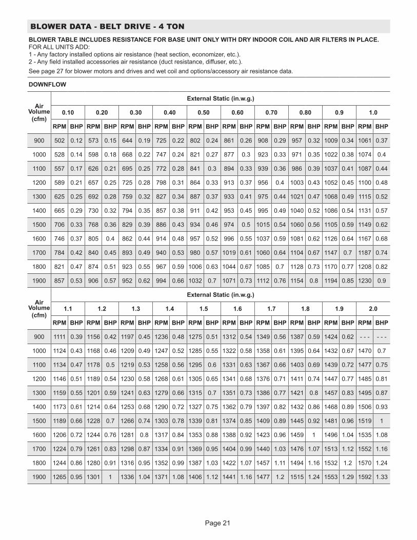
Page 21
BLOWER DATA - BELT DRIVE - 4 TONBLOWER TABLE INCLUDES RESISTANCE FOR BASE UNIT ONLY WITH DRY INDOOR COIL AND AIR FILTERS IN PLACE. FOR ALL UNITS ADD: 1 - Any factory installed options air resistance (heat section, economizer, etc.). 2 - Any field installed accessories air resistance (duct resistance, diffuser, etc.).See page 27 for blower motors and drives and wet coil and options/accessory air resistance data.
DOWNFLOW
Air Volume (cfm)
External Static (in.w.g.)
0.10 0.20 0.30 0.40 0.50 0.60 0.70 0.80 0.9 1.0
RPM BHP RPM BHP RPM BHP RPM BHP RPM BHP RPM BHP RPM BHP RPM BHP RPM BHP RPM BHP
900 502 0.12 573 0.15 644 0.19 725 0.22 802 0.24 861 0.26 908 0.29 957 0.32 1009 0.34 1061 0.37
1000 528 0.14 598 0.18 668 0.22 747 0.24 821 0.27 877 0.3 923 0.33 971 0.35 1022 0.38 1074 0.4
1100 557 0.17 626 0.21 695 0.25 772 0.28 841 0.3 894 0.33 939 0.36 986 0.39 1037 0.41 1087 0.44
1200 589 0.21 657 0.25 725 0.28 798 0.31 864 0.33 913 0.37 956 0.4 1003 0.43 1052 0.45 1100 0.48
1300 625 0.25 692 0.28 759 0.32 827 0.34 887 0.37 933 0.41 975 0.44 1021 0.47 1068 0.49 1115 0.52
1400 665 0.29 730 0.32 794 0.35 857 0.38 911 0.42 953 0.45 995 0.49 1040 0.52 1086 0.54 1131 0.57
1500 706 0.33 768 0.36 829 0.39 886 0.43 934 0.46 974 0.5 1015 0.54 1060 0.56 1105 0.59 1149 0.62
1600 746 0.37 805 0.4 862 0.44 914 0.48 957 0.52 996 0.55 1037 0.59 1081 0.62 1126 0.64 1167 0.68
1700 784 0.42 840 0.45 893 0.49 940 0.53 980 0.57 1019 0.61 1060 0.64 1104 0.67 1147 0.7 1187 0.74
1800 821 0.47 874 0.51 923 0.55 967 0.59 1006 0.63 1044 0.67 1085 0.7 1128 0.73 1170 0.77 1208 0.82
1900 857 0.53 906 0.57 952 0.62 994 0.66 1032 0.7 1071 0.73 1112 0.76 1154 0.8 1194 0.85 1230 0.9
Air Volume (cfm)
External Static (in.w.g.)
1.1 1.2 1.3 1.4 1.5 1.6 1.7 1.8 1.9 2.0
RPM BHP RPM BHP RPM BHP RPM BHP RPM BHP RPM BHP RPM BHP RPM BHP RPM BHP RPM BHP
900 1111 0.39 1156 0.42 1197 0.45 1236 0.48 1275 0.51 1312 0.54 1349 0.56 1387 0.59 1424 0.62 - - - - - -
1000 1124 0.43 1168 0.46 1209 0.49 1247 0.52 1285 0.55 1322 0.58 1358 0.61 1395 0.64 1432 0.67 1470 0.7
1100 1134 0.47 1178 0.5 1219 0.53 1258 0.56 1295 0.6 1331 0.63 1367 0.66 1403 0.69 1439 0.72 1477 0.75
1200 1146 0.51 1189 0.54 1230 0.58 1268 0.61 1305 0.65 1341 0.68 1376 0.71 1411 0.74 1447 0.77 1485 0.81
1300 1159 0.55 1201 0.59 1241 0.63 1279 0.66 1315 0.7 1351 0.73 1386 0.77 1421 0.8 1457 0.83 1495 0.87
1400 1173 0.61 1214 0.64 1253 0.68 1290 0.72 1327 0.75 1362 0.79 1397 0.82 1432 0.86 1468 0.89 1506 0.93
1500 1189 0.66 1228 0.7 1266 0.74 1303 0.78 1339 0.81 1374 0.85 1409 0.89 1445 0.92 1481 0.96 1519 1
1600 1206 0.72 1244 0.76 1281 0.8 1317 0.84 1353 0.88 1388 0.92 1423 0.96 1459 1 1496 1.04 1535 1.08
1700 1224 0.79 1261 0.83 1298 0.87 1334 0.91 1369 0.95 1404 0.99 1440 1.03 1476 1.07 1513 1.12 1552 1.16
1800 1244 0.86 1280 0.91 1316 0.95 1352 0.99 1387 1.03 1422 1.07 1457 1.11 1494 1.16 1532 1.2 1570 1.24
1900 1265 0.95 1301 1 1336 1.04 1371 1.08 1406 1.12 1441 1.16 1477 1.2 1515 1.24 1553 1.29 1592 1.33
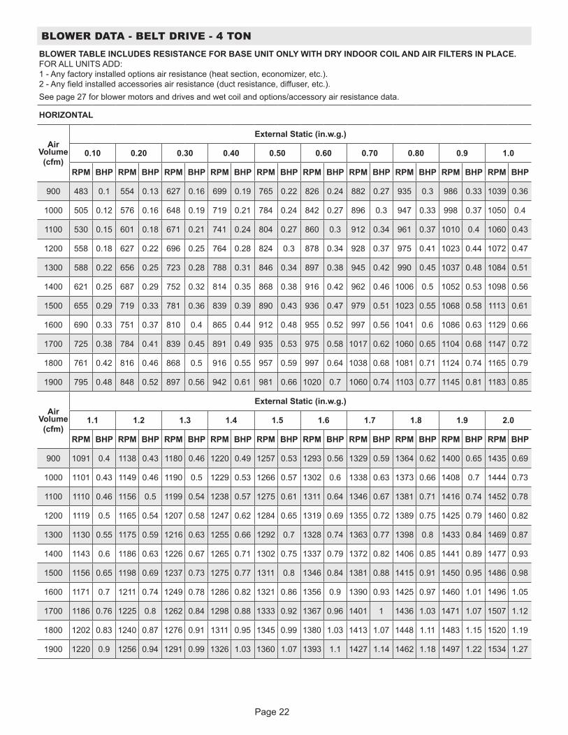
Page 22
BLOWER DATA - BELT DRIVE - 4 TONBLOWER TABLE INCLUDES RESISTANCE FOR BASE UNIT ONLY WITH DRY INDOOR COIL AND AIR FILTERS IN PLACE. FOR ALL UNITS ADD: 1 - Any factory installed options air resistance (heat section, economizer, etc.). 2 - Any field installed accessories air resistance (duct resistance, diffuser, etc.).See page 27 for blower motors and drives and wet coil and options/accessory air resistance data.
HORIZONTAL
Air Volume (cfm)
External Static (in.w.g.)
0.10 0.20 0.30 0.40 0.50 0.60 0.70 0.80 0.9 1.0
RPM BHP RPM BHP RPM BHP RPM BHP RPM BHP RPM BHP RPM BHP RPM BHP RPM BHP RPM BHP
900 483 0.1 554 0.13 627 0.16 699 0.19 765 0.22 826 0.24 882 0.27 935 0.3 986 0.33 1039 0.36
1000 505 0.12 576 0.16 648 0.19 719 0.21 784 0.24 842 0.27 896 0.3 947 0.33 998 0.37 1050 0.4
1100 530 0.15 601 0.18 671 0.21 741 0.24 804 0.27 860 0.3 912 0.34 961 0.37 1010 0.4 1060 0.43
1200 558 0.18 627 0.22 696 0.25 764 0.28 824 0.3 878 0.34 928 0.37 975 0.41 1023 0.44 1072 0.47
1300 588 0.22 656 0.25 723 0.28 788 0.31 846 0.34 897 0.38 945 0.42 990 0.45 1037 0.48 1084 0.51
1400 621 0.25 687 0.29 752 0.32 814 0.35 868 0.38 916 0.42 962 0.46 1006 0.5 1052 0.53 1098 0.56
1500 655 0.29 719 0.33 781 0.36 839 0.39 890 0.43 936 0.47 979 0.51 1023 0.55 1068 0.58 1113 0.61
1600 690 0.33 751 0.37 810 0.4 865 0.44 912 0.48 955 0.52 997 0.56 1041 0.6 1086 0.63 1129 0.66
1700 725 0.38 784 0.41 839 0.45 891 0.49 935 0.53 975 0.58 1017 0.62 1060 0.65 1104 0.68 1147 0.72
1800 761 0.42 816 0.46 868 0.5 916 0.55 957 0.59 997 0.64 1038 0.68 1081 0.71 1124 0.74 1165 0.79
1900 795 0.48 848 0.52 897 0.56 942 0.61 981 0.66 1020 0.7 1060 0.74 1103 0.77 1145 0.81 1183 0.85
Air Volume (cfm)
External Static (in.w.g.)
1.1 1.2 1.3 1.4 1.5 1.6 1.7 1.8 1.9 2.0
RPM BHP RPM BHP RPM BHP RPM BHP RPM BHP RPM BHP RPM BHP RPM BHP RPM BHP RPM BHP
900 1091 0.4 1138 0.43 1180 0.46 1220 0.49 1257 0.53 1293 0.56 1329 0.59 1364 0.62 1400 0.65 1435 0.69
1000 1101 0.43 1149 0.46 1190 0.5 1229 0.53 1266 0.57 1302 0.6 1338 0.63 1373 0.66 1408 0.7 1444 0.73
1100 1110 0.46 1156 0.5 1199 0.54 1238 0.57 1275 0.61 1311 0.64 1346 0.67 1381 0.71 1416 0.74 1452 0.78
1200 1119 0.5 1165 0.54 1207 0.58 1247 0.62 1284 0.65 1319 0.69 1355 0.72 1389 0.75 1425 0.79 1460 0.82
1300 1130 0.55 1175 0.59 1216 0.63 1255 0.66 1292 0.7 1328 0.74 1363 0.77 1398 0.8 1433 0.84 1469 0.87
1400 1143 0.6 1186 0.63 1226 0.67 1265 0.71 1302 0.75 1337 0.79 1372 0.82 1406 0.85 1441 0.89 1477 0.93
1500 1156 0.65 1198 0.69 1237 0.73 1275 0.77 1311 0.8 1346 0.84 1381 0.88 1415 0.91 1450 0.95 1486 0.98
1600 1171 0.7 1211 0.74 1249 0.78 1286 0.82 1321 0.86 1356 0.9 1390 0.93 1425 0.97 1460 1.01 1496 1.05
1700 1186 0.76 1225 0.8 1262 0.84 1298 0.88 1333 0.92 1367 0.96 1401 1 1436 1.03 1471 1.07 1507 1.12
1800 1202 0.83 1240 0.87 1276 0.91 1311 0.95 1345 0.99 1380 1.03 1413 1.07 1448 1.11 1483 1.15 1520 1.19
1900 1220 0.9 1256 0.94 1291 0.99 1326 1.03 1360 1.07 1393 1.1 1427 1.14 1462 1.18 1497 1.22 1534 1.27
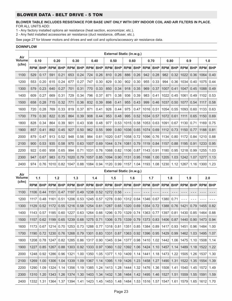
Page 23
BLOWER DATA - BELT DRIVE - 5 TONBLOWER TABLE INCLUDES RESISTANCE FOR BASE UNIT ONLY WITH DRY INDOOR COIL AND AIR FILTERS IN PLACE. FOR ALL UNITS ADD: 1 - Any factory installed options air resistance (heat section, economizer, etc.). 2 - Any field installed accessories air resistance (duct resistance, diffuser, etc.).See page 27 for blower motors and drives and wet coil and options/accessory air resistance data.
DOWNFLOW
Air Volume (cfm)
External Static (in.w.g.)
0.10 0.20 0.30 0.40 0.50 0.60 0.70 0.80 0.9 1.0
RPM BHP RPM BHP RPM BHP RPM BHP RPM BHP RPM BHP RPM BHP RPM BHP RPM BHP RPM BHP
1100 529 0.17 591 0.21 653 0.24 724 0.26 810 0.26 886 0.26 942 0.28 982 0.32 1022 0.36 1064 0.40
1200 553 0.20 615 0.24 677 0.27 747 0.30 829 0.30 902 0.30 955 0.33 994 0.36 1034 0.40 1075 0.44
1300 579 0.23 640 0.27 701 0.31 770 0.33 850 0.34 918 0.35 969 0.37 1007 0.41 1047 0.45 1088 0.49
1400 609 0.27 669 0.31 729 0.34 796 0.37 871 0.38 936 0.39 983 0.41 1022 0.45 1061 0.49 1102 0.53
1500 658 0.28 715 0.32 771 0.36 832 0.39 898 0.41 955 0.43 999 0.46 1037 0.50 1077 0.54 1117 0.58
1600 720 0.28 769 0.33 819 0.37 871 0.41 926 0.44 975 0.47 1016 0.51 1054 0.55 1093 0.60 1133 0.63
1700 779 0.30 822 0.35 864 0.39 908 0.44 953 0.48 995 0.52 1034 0.57 1072 0.61 1111 0.65 1150 0.69
1800 828 0.34 864 0.39 901 0.43 938 0.48 977 0.53 1015 0.58 1053 0.63 1091 0.67 1130 0.71 1169 0.75
1900 857 0.41 892 0.45 927 0.50 962 0.55 999 0.60 1036 0.65 1074 0.69 1112 0.73 1150 0.77 1188 0.81
2000 879 0.47 913 0.52 948 0.56 984 0.61 1020 0.67 1058 0.72 1096 0.76 1134 0.80 1172 0.84 1210 0.88
2100 900 0.53 935 0.58 970 0.63 1007 0.69 1044 0.74 1081 0.79 1119 0.84 1157 0.88 1195 0.91 1233 0.95
2200 922 0.60 958 0.65 994 0.71 1031 0.76 1068 0.82 1106 0.87 1143 0.91 1180 0.95 1218 0.99 1255 1.03
2300 947 0.67 983 0.73 1020 0.79 1057 0.85 1094 0.90 1131 0.95 1168 1.00 1205 1.03 1242 1.07 1277 1.13
2400 974 0.76 1010 0.82 1047 0.88 1084 0.94 1120 0.99 1157 1.04 1193 1.08 1230 1.12 1267 1.16 1300 1.23
Air Volume (cfm)
External Static (in.w.g.)
1.1 1.2 1.3 1.4 1.5 1.6 1.7 1.8 1.9 2.0
RPM BHP RPM BHP RPM BHP RPM BHP RPM BHP RPM BHP RPM BHP RPM BHP RPM BHP RPM BHP
1100 1106 0.44 1151 0.47 1197 0.49 1238 0.52 1272 0.56 - - - - - - - - - - - - - - - - - - - - - - - - - - - - - -
1200 1117 0.48 1161 0.51 1206 0.53 1245 0.57 1278 0.60 1312 0.64 1346 0.67 1380 0.71 - - - - - - - - - - - -
1300 1129 0.52 1172 0.55 1216 0.58 1254 0.61 1287 0.65 1320 0.69 1354 0.72 1388 0.76 1421 0.79 1455 0.82
1400 1143 0.57 1185 0.60 1227 0.63 1264 0.66 1296 0.70 1329 0.74 1363 0.77 1397 0.81 1430 0.85 1464 0.88
1500 1157 0.62 1199 0.65 1239 0.68 1275 0.71 1306 0.75 1339 0.79 1373 0.83 1406 0.87 1440 0.90 1473 0.94
1600 1173 0.67 1214 0.70 1253 0.73 1288 0.77 1318 0.81 1351 0.85 1384 0.89 1417 0.93 1451 0.96 1484 1.00
1700 1190 0.72 1230 0.76 1268 0.79 1301 0.83 1331 0.87 1363 0.92 1396 0.95 1429 0.99 1462 1.03 1495 1.07
1800 1208 0.78 1247 0.82 1285 0.86 1317 0.90 1345 0.94 1377 0.98 1410 1.02 1442 1.06 1475 1.10 1508 1.14
1900 1227 0.85 1267 0.88 1303 0.92 1333 0.97 1360 1.02 1392 1.06 1424 1.10 1457 1.14 1489 1.18 1522 1.22
2000 1248 0.92 1286 0.96 1321 1.00 1350 1.05 1377 1.10 1409 1.14 1441 1.18 1473 1.22 1505 1.26 1537 1.30
2100 1269 1.00 1306 1.04 1339 1.09 1367 1.14 1395 1.19 1426 1.23 1458 1.27 1490 1.31 1522 1.35 1554 1.39
2200 1290 1.09 1324 1.14 1356 1.19 1385 1.24 1413 1.28 1444 1.32 1476 1.36 1508 1.41 1540 1.45 1572 1.49
2300 1310 1.20 1343 1.26 1374 1.30 1403 1.34 1432 1.38 1464 1.42 1495 1.46 1527 1.51 1559 1.55 1591 1.59
2400 1332 1.31 1364 1.37 1394 1.41 1423 1.45 1453 1.48 1484 1.53 1516 1.57 1547 1.61 1579 1.65 1612 1.70
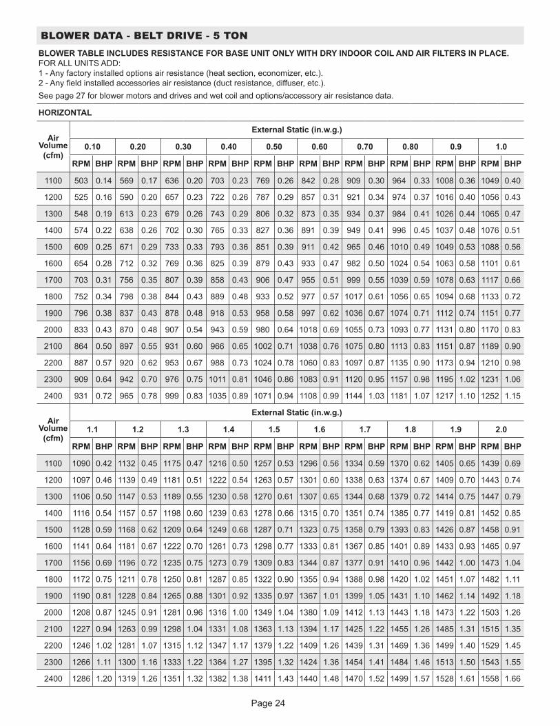
Page 24
BLOWER DATA - BELT DRIVE - 5 TONBLOWER TABLE INCLUDES RESISTANCE FOR BASE UNIT ONLY WITH DRY INDOOR COIL AND AIR FILTERS IN PLACE. FOR ALL UNITS ADD: 1 - Any factory installed options air resistance (heat section, economizer, etc.). 2 - Any field installed accessories air resistance (duct resistance, diffuser, etc.).See page 27 for blower motors and drives and wet coil and options/accessory air resistance data.
HORIZONTAL
Air Volume (cfm)
External Static (in.w.g.)
0.10 0.20 0.30 0.40 0.50 0.60 0.70 0.80 0.9 1.0
RPM BHP RPM BHP RPM BHP RPM BHP RPM BHP RPM BHP RPM BHP RPM BHP RPM BHP RPM BHP
1100 503 0.14 569 0.17 636 0.20 703 0.23 769 0.26 842 0.28 909 0.30 964 0.33 1008 0.36 1049 0.40
1200 525 0.16 590 0.20 657 0.23 722 0.26 787 0.29 857 0.31 921 0.34 974 0.37 1016 0.40 1056 0.43
1300 548 0.19 613 0.23 679 0.26 743 0.29 806 0.32 873 0.35 934 0.37 984 0.41 1026 0.44 1065 0.47
1400 574 0.22 638 0.26 702 0.30 765 0.33 827 0.36 891 0.39 949 0.41 996 0.45 1037 0.48 1076 0.51
1500 609 0.25 671 0.29 733 0.33 793 0.36 851 0.39 911 0.42 965 0.46 1010 0.49 1049 0.53 1088 0.56
1600 654 0.28 712 0.32 769 0.36 825 0.39 879 0.43 933 0.47 982 0.50 1024 0.54 1063 0.58 1101 0.61
1700 703 0.31 756 0.35 807 0.39 858 0.43 906 0.47 955 0.51 999 0.55 1039 0.59 1078 0.63 1117 0.66
1800 752 0.34 798 0.38 844 0.43 889 0.48 933 0.52 977 0.57 1017 0.61 1056 0.65 1094 0.68 1133 0.72
1900 796 0.38 837 0.43 878 0.48 918 0.53 958 0.58 997 0.62 1036 0.67 1074 0.71 1112 0.74 1151 0.77
2000 833 0.43 870 0.48 907 0.54 943 0.59 980 0.64 1018 0.69 1055 0.73 1093 0.77 1131 0.80 1170 0.83
2100 864 0.50 897 0.55 931 0.60 966 0.65 1002 0.71 1038 0.76 1075 0.80 1113 0.83 1151 0.87 1189 0.90
2200 887 0.57 920 0.62 953 0.67 988 0.73 1024 0.78 1060 0.83 1097 0.87 1135 0.90 1173 0.94 1210 0.98
2300 909 0.64 942 0.70 976 0.75 1011 0.81 1046 0.86 1083 0.91 1120 0.95 1157 0.98 1195 1.02 1231 1.06
2400 931 0.72 965 0.78 999 0.83 1035 0.89 1071 0.94 1108 0.99 1144 1.03 1181 1.07 1217 1.10 1252 1.15
Air Volume (cfm)
External Static (in.w.g.)
1.1 1.2 1.3 1.4 1.5 1.6 1.7 1.8 1.9 2.0
RPM BHP RPM BHP RPM BHP RPM BHP RPM BHP RPM BHP RPM BHP RPM BHP RPM BHP RPM BHP
1100 1090 0.42 1132 0.45 1175 0.47 1216 0.50 1257 0.53 1296 0.56 1334 0.59 1370 0.62 1405 0.65 1439 0.69
1200 1097 0.46 1139 0.49 1181 0.51 1222 0.54 1263 0.57 1301 0.60 1338 0.63 1374 0.67 1409 0.70 1443 0.74
1300 1106 0.50 1147 0.53 1189 0.55 1230 0.58 1270 0.61 1307 0.65 1344 0.68 1379 0.72 1414 0.75 1447 0.79
1400 1116 0.54 1157 0.57 1198 0.60 1239 0.63 1278 0.66 1315 0.70 1351 0.74 1385 0.77 1419 0.81 1452 0.85
1500 1128 0.59 1168 0.62 1209 0.64 1249 0.68 1287 0.71 1323 0.75 1358 0.79 1393 0.83 1426 0.87 1458 0.91
1600 1141 0.64 1181 0.67 1222 0.70 1261 0.73 1298 0.77 1333 0.81 1367 0.85 1401 0.89 1433 0.93 1465 0.97
1700 1156 0.69 1196 0.72 1235 0.75 1273 0.79 1309 0.83 1344 0.87 1377 0.91 1410 0.96 1442 1.00 1473 1.04
1800 1172 0.75 1211 0.78 1250 0.81 1287 0.85 1322 0.90 1355 0.94 1388 0.98 1420 1.02 1451 1.07 1482 1.11
1900 1190 0.81 1228 0.84 1265 0.88 1301 0.92 1335 0.97 1367 1.01 1399 1.05 1431 1.10 1462 1.14 1492 1.18
2000 1208 0.87 1245 0.91 1281 0.96 1316 1.00 1349 1.04 1380 1.09 1412 1.13 1443 1.18 1473 1.22 1503 1.26
2100 1227 0.94 1263 0.99 1298 1.04 1331 1.08 1363 1.13 1394 1.17 1425 1.22 1455 1.26 1485 1.31 1515 1.35
2200 1246 1.02 1281 1.07 1315 1.12 1347 1.17 1379 1.22 1409 1.26 1439 1.31 1469 1.36 1499 1.40 1529 1.45
2300 1266 1.11 1300 1.16 1333 1.22 1364 1.27 1395 1.32 1424 1.36 1454 1.41 1484 1.46 1513 1.50 1543 1.55
2400 1286 1.20 1319 1.26 1351 1.32 1382 1.38 1411 1.43 1440 1.48 1470 1.52 1499 1.57 1528 1.61 1558 1.66

Page 25
BLOWER DATA - BELT DRIVE - 6 TONBLOWER TABLE INCLUDES RESISTANCE FOR BASE UNIT ONLY WITH DRY INDOOR COIL AND AIR FILTERS IN PLACE. FOR ALL UNITS ADD: 1 - Any factory installed options air resistance (heat section, economizer, etc.). 2 - Any field installed accessories air resistance (duct resistance, diffuser, etc.).See page 27 for blower motors and drives and wet coil and options/accessory air resistance data.
DOWNFLOW
Air Volume (cfm)
External Static (in.w.g.)
0.10 0.20 0.30 0.40 0.50 0.60 0.70 0.80 0.9 1.0
RPM BHP RPM BHP RPM BHP RPM BHP RPM BHP RPM BHP RPM BHP RPM BHP RPM BHP RPM BHP
1900 510 0.45 544 0.5 579 0.55 614 0.6 649 0.65 684 0.7 718 0.74 752 0.79 784 0.83 812 0.88
2000 526 0.49 560 0.55 595 0.6 629 0.65 663 0.7 697 0.75 730 0.79 763 0.84 794 0.88 820 0.93
2100 542 0.54 576 0.59 610 0.65 644 0.7 678 0.75 711 0.8 743 0.84 775 0.89 804 0.94 830 0.98
2200 560 0.59 593 0.64 627 0.7 660 0.75 693 0.8 725 0.85 757 0.9 787 0.94 814 0.99 840 1.03
2300 578 0.64 610 0.7 644 0.75 676 0.81 709 0.86 740 0.91 770 0.95 799 1 826 1.05 851 1.09
2400 597 0.7 629 0.75 661 0.81 693 0.86 725 0.91 755 0.96 784 1.01 812 1.06 838 1.11 862 1.15
2500 617 0.76 648 0.81 679 0.87 710 0.92 741 0.97 770 1.03 799 1.08 825 1.13 850 1.17 875 1.22
2600 637 0.82 667 0.87 698 0.93 728 0.98 758 1.04 786 1.09 814 1.15 839 1.2 864 1.24 887 1.28
2700 658 0.88 687 0.94 717 1 746 1.05 775 1.11 802 1.16 829 1.22 853 1.27 877 1.31 901 1.36
2800 679 0.95 708 1.01 736 1.07 764 1.12 792 1.18 819 1.24 844 1.3 868 1.35 892 1.39 915 1.43
2900 701 1.02 728 1.08 756 1.14 783 1.2 809 1.26 835 1.32 860 1.38 884 1.43 907 1.47 930 1.52
Air Volume (cfm)
External Static (in.w.g.)
1.1 1.2 1.3 1.4 1.5 1.6 1.7 1.8 1.9 2.0
RPM BHP RPM BHP RPM BHP RPM BHP RPM BHP RPM BHP RPM BHP RPM BHP RPM BHP RPM BHP
1900 837 0.92 861 0.96 886 1 913 1.04 939 1.07 966 1.11 992 1.16 1017 1.21 1041 1.27 1065 1.33
2000 845 0.97 870 1.01 895 1.05 921 1.09 948 1.12 974 1.17 999 1.22 1023 1.27 1047 1.33 1070 1.39
2100 855 1.02 879 1.06 904 1.1 930 1.14 956 1.18 982 1.22 1006 1.28 1030 1.34 1053 1.4 1075 1.46
2200 865 1.08 889 1.12 914 1.15 940 1.19 966 1.24 990 1.29 1014 1.34 1037 1.41 1059 1.47 1081 1.54
2300 875 1.13 900 1.17 925 1.21 951 1.25 976 1.3 999 1.35 1022 1.41 1044 1.48 1066 1.55 1087 1.62
2400 887 1.19 912 1.23 936 1.27 961 1.32 986 1.37 1009 1.43 1031 1.49 1052 1.57 1073 1.64 1094 1.71
2500 899 1.25 923 1.29 948 1.34 973 1.39 996 1.44 1018 1.51 1039 1.58 1060 1.65 1080 1.73 1101 1.8
2600 912 1.32 936 1.36 960 1.41 984 1.46 1007 1.52 1028 1.59 1049 1.67 1069 1.75 1089 1.82 1109 1.89
2700 925 1.4 949 1.44 973 1.49 996 1.55 1018 1.61 1038 1.69 1058 1.76 1078 1.84 1098 1.92 1118 1.99
2800 939 1.47 962 1.52 985 1.57 1008 1.64 1029 1.71 1049 1.79 1069 1.87 1088 1.94 1107 2.02 1127 2.09
2900 953 1.56 976 1.61 998 1.67 1020 1.73 1041 1.81 1060 1.89 1079 1.98 1098 2.06 1117 2.13 1137 2.21
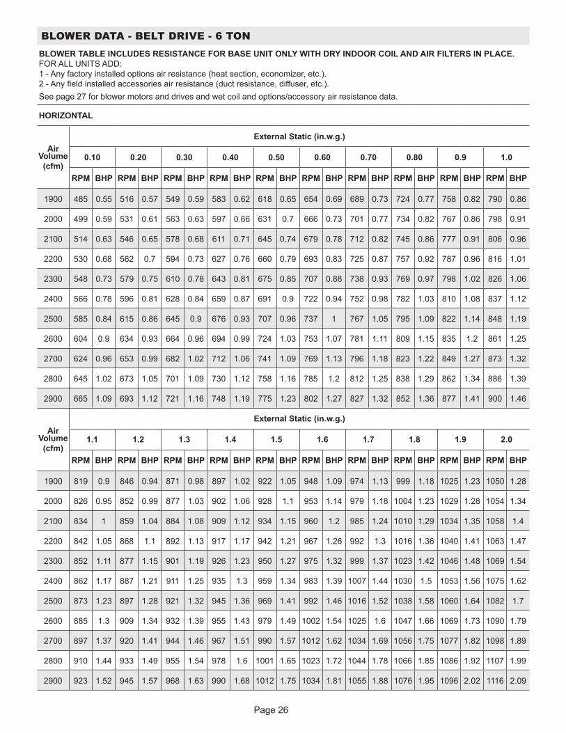
Page 26
BLOWER DATA - BELT DRIVE - 6 TONBLOWER TABLE INCLUDES RESISTANCE FOR BASE UNIT ONLY WITH DRY INDOOR COIL AND AIR FILTERS IN PLACE. FOR ALL UNITS ADD: 1 - Any factory installed options air resistance (heat section, economizer, etc.). 2 - Any field installed accessories air resistance (duct resistance, diffuser, etc.).See page 27 for blower motors and drives and wet coil and options/accessory air resistance data.
HORIZONTAL
Air Volume (cfm)
External Static (in.w.g.)
0.10 0.20 0.30 0.40 0.50 0.60 0.70 0.80 0.9 1.0
RPM BHP RPM BHP RPM BHP RPM BHP RPM BHP RPM BHP RPM BHP RPM BHP RPM BHP RPM BHP
1900 485 0.55 516 0.57 549 0.59 583 0.62 618 0.65 654 0.69 689 0.73 724 0.77 758 0.82 790 0.86
2000 499 0.59 531 0.61 563 0.63 597 0.66 631 0.7 666 0.73 701 0.77 734 0.82 767 0.86 798 0.91
2100 514 0.63 546 0.65 578 0.68 611 0.71 645 0.74 679 0.78 712 0.82 745 0.86 777 0.91 806 0.96
2200 530 0.68 562 0.7 594 0.73 627 0.76 660 0.79 693 0.83 725 0.87 757 0.92 787 0.96 816 1.01
2300 548 0.73 579 0.75 610 0.78 643 0.81 675 0.85 707 0.88 738 0.93 769 0.97 798 1.02 826 1.06
2400 566 0.78 596 0.81 628 0.84 659 0.87 691 0.9 722 0.94 752 0.98 782 1.03 810 1.08 837 1.12
2500 585 0.84 615 0.86 645 0.9 676 0.93 707 0.96 737 1 767 1.05 795 1.09 822 1.14 848 1.19
2600 604 0.9 634 0.93 664 0.96 694 0.99 724 1.03 753 1.07 781 1.11 809 1.15 835 1.2 861 1.25
2700 624 0.96 653 0.99 682 1.02 712 1.06 741 1.09 769 1.13 796 1.18 823 1.22 849 1.27 873 1.32
2800 645 1.02 673 1.05 701 1.09 730 1.12 758 1.16 785 1.2 812 1.25 838 1.29 862 1.34 886 1.39
2900 665 1.09 693 1.12 721 1.16 748 1.19 775 1.23 802 1.27 827 1.32 852 1.36 877 1.41 900 1.46
Air Volume (cfm)
External Static (in.w.g.)
1.1 1.2 1.3 1.4 1.5 1.6 1.7 1.8 1.9 2.0
RPM BHP RPM BHP RPM BHP RPM BHP RPM BHP RPM BHP RPM BHP RPM BHP RPM BHP RPM BHP
1900 819 0.9 846 0.94 871 0.98 897 1.02 922 1.05 948 1.09 974 1.13 999 1.18 1025 1.23 1050 1.28
2000 826 0.95 852 0.99 877 1.03 902 1.06 928 1.1 953 1.14 979 1.18 1004 1.23 1029 1.28 1054 1.34
2100 834 1 859 1.04 884 1.08 909 1.12 934 1.15 960 1.2 985 1.24 1010 1.29 1034 1.35 1058 1.4
2200 842 1.05 868 1.1 892 1.13 917 1.17 942 1.21 967 1.26 992 1.3 1016 1.36 1040 1.41 1063 1.47
2300 852 1.11 877 1.15 901 1.19 926 1.23 950 1.27 975 1.32 999 1.37 1023 1.42 1046 1.48 1069 1.54
2400 862 1.17 887 1.21 911 1.25 935 1.3 959 1.34 983 1.39 1007 1.44 1030 1.5 1053 1.56 1075 1.62
2500 873 1.23 897 1.28 921 1.32 945 1.36 969 1.41 992 1.46 1016 1.52 1038 1.58 1060 1.64 1082 1.7
2600 885 1.3 909 1.34 932 1.39 955 1.43 979 1.49 1002 1.54 1025 1.6 1047 1.66 1069 1.73 1090 1.79
2700 897 1.37 920 1.41 944 1.46 967 1.51 990 1.57 1012 1.62 1034 1.69 1056 1.75 1077 1.82 1098 1.89
2800 910 1.44 933 1.49 955 1.54 978 1.6 1001 1.65 1023 1.72 1044 1.78 1066 1.85 1086 1.92 1107 1.99
2900 923 1.52 945 1.57 968 1.63 990 1.68 1012 1.75 1034 1.81 1055 1.88 1076 1.95 1096 2.02 1116 2.09
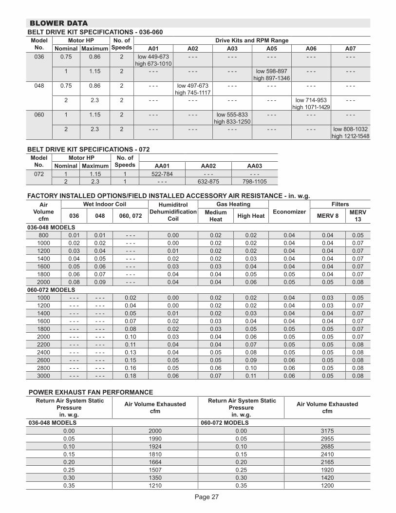
Page 27
BLOWER DATABELT DRIVE KIT SPECIFICATIONS - 036-060
Model No.
Motor HP No. of Speeds
Drive Kits and RPM RangeNominal Maximum A01 A02 A03 A05 A06 A07
036 0.75 0.86 2 low 449-673 high 673-1010
- - - - - - - - - - - - - - -
1 1.15 2 - - - - - - - - - low 598-897 high 897-1346
- - - - - -
048 0.75 0.86 2 - - - low 497-673 high 745-1117
- - - - - - - - - - - -
2 2.3 2 - - - - - - - - - - - - low 714-953 high 1071-1429
- - -
060 1 1.15 2 - - - - - - low 555-833 high 833-1250
- - - - - - - - -
2 2.3 2 - - - - - - - - - - - - - - - low 808-1032 high 1212-1548
BELT DRIVE KIT SPECIFICATIONS - 072Model
No.Motor HP No. of
SpeedsNominal Maximum AA01 AA02 AA03072 1 1.15 1 522-784 - - - - - -
2 2.3 1 - - - 632-875 798-1105
FACTORY INSTALLED OPTIONS/FIELD INSTALLED ACCESSORY AIR RESISTANCE - in. w.g.Air
Volume cfm
Wet Indoor Coil Humiditrol Dehumidification
Coil
Gas HeatingEconomizer
Filters
036 048 060, 072 Medium Heat High Heat MERV 8 MERV
13036-048 MODELS
800 0.01 0.01 - - - 0.00 0.02 0.02 0.04 0.04 0.051000 0.02 0.02 - - - 0.00 0.02 0.02 0.04 0.04 0.071200 0.03 0.04 - - - 0.01 0.02 0.02 0.04 0.04 0.071400 0.04 0.05 - - - 0.02 0.02 0.03 0.04 0.04 0.071600 0.05 0.06 - - - 0.03 0.03 0.04 0.04 0.04 0.071800 0.06 0.07 - - - 0.04 0.04 0.05 0.05 0.04 0.072000 0.08 0.09 - - - 0.04 0.04 0.06 0.05 0.05 0.08
060-072 MODELS1000 - - - - - - 0.02 0.00 0.02 0.02 0.04 0.03 0.051200 - - - - - - 0.04 0.00 0.02 0.02 0.04 0.03 0.071400 - - - - - - 0.05 0.01 0.02 0.03 0.04 0.04 0.071600 - - - - - - 0.07 0.02 0.03 0.04 0.04 0.04 0.071800 - - - - - - 0.08 0.02 0.03 0.05 0.05 0.05 0.072000 - - - - - - 0.10 0.03 0.04 0.06 0.05 0.05 0.072200 - - - - - - 0.11 0.04 0.04 0.07 0.05 0.05 0.082400 - - - - - - 0.13 0.04 0.05 0.08 0.05 0.05 0.082600 - - - - - - 0.15 0.05 0.05 0.09 0.06 0.05 0.082800 - - - - - - 0.16 0.05 0.06 0.10 0.06 0.05 0.083000 - - - - - - 0.18 0.06 0.07 0.11 0.06 0.05 0.08
POWER EXHAUST FAN PERFORMANCE Return Air System Static
Pressure in. w.g.
Air Volume Exhausted cfm
Return Air System Static Pressure in. w.g.
Air Volume Exhausted cfm
036-048 MODELS 060-072 MODELS0.00 2000 0.00 31750.05 1990 0.05 29550.10 1924 0.10 26850.15 1810 0.15 24100.20 1664 0.20 21650.25 1507 0.25 19200.30 1350 0.30 14200.35 1210 0.35 1200
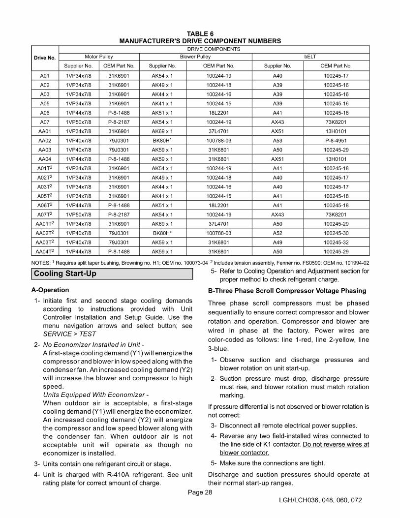
Page 28
LGH/LCH036, 048, 060, 072
TABLE 6MANUFACTURER'S DRIVE COMPONENT NUMBERS
Drive No.
DRIVE COMPONENTS
Motor Pulley Blower Pulley bELT
Supplier No. OEM Part No. Supplier No. OEM Part No. Supplier No. OEM Part No.
A01 1VP34x7/8 31K6901 AK54 x 1 100244-19 A40 100245-17
A02 1VP34x7/8 31K6901 AK49 x 1 100244-18 A39 100245-16
A03 1VP34x7/8 31K6901 AK44 x 1 100244-16 A39 100245-16
A05 1VP34x7/8 31K6901 AK41 x 1 100244-15 A39 100245-16
A06 1VP44x7/8 P-8-1488 AK51 x 1 18L2201 A41 100245-18
A07 1VP50x7/8 P-8-2187 AK54 x 1 100244-19 AX43 73K8201
AA01 1VP34x7/8 31K6901 AK69 x 1 37L4701 AX51 13H0101
AA02 1VP40x7/8 79J0301 BK80H1 100788-03 A53 P-8-4951
AA03 1VP40x7/8 79J0301 AK59 x 1 31K6801 A50 100245-29
AA04 1VP44x7/8 P-8-1488 AK59 x 1 31K6801 AX51 13H0101
A01T2 1VP34x7/8 31K6901 AK54 x 1 100244-19 A41 100245-18
A02T2 1VP34x7/8 31K6901 AK49 x 1 100244-18 A40 100245-17
A03T2 1VP34x7/8 31K6901 AK44 x 1 100244-16 A40 100245-17
A05T2 1VP34x7/8 31K6901 AK41 x 1 100244-15 A41 100245-18
A06T2 1VP44x7/8 P-8-1488 AK51 x 1 18L2201 A41 100245-18
A07T2 1VP50x7/8 P-8-2187 AK54 x 1 100244-19 AX43 73K8201
AA01T2 1VP34x7/8 31K6901 AK69 x 1 37L4701 A50 100245-29
AA02T2 1VP40x7/8 79J0301 BK80H* 100788-03 A52 100245-30
AA03T2 1VP40x7/8 79J0301 AK59 x 1 31K6801 A49 100245-32
AA04T2 1VP44x7/8 P-8-1488 AK59 x 1 31K6801 A50 100245-29
NOTES: 1 Requires split taper bushing, Browning no. H1; OEM no. 100073-04 2 Includes tension assembly, Fenner no. FS0590; OEM no. 101994-02
Cooling Start-Up
A-Operation
1- Initiate first and second stage cooling demands
according to instructions provided with Unit
Controller Installation and Setup Guide. Use the
menu navigation arrows and select button; see
SERVICE > TEST
2- No Economizer Installed in Unit -
A first-stage cooling demand (Y1) will energize the
compressor and blower in low speed along with the
condenser fan. An increased cooling demand (Y2)
will increase the blower and compressor to high
speed.
Units Equipped With Economizer -
When outdoor air is acceptable, a first-stage
cooling demand (Y1) will energize the economizer.
An increased cooling demand (Y2) will energize
the compressor and low speed blower along with
the condenser fan. When outdoor air is not
acceptable unit will operate as though no
economizer is installed.
3- Units contain one refrigerant circuit or stage.
4- Unit is charged with R-410A refrigerant. See unit
rating plate for correct amount of charge.
5- Refer to Cooling Operation and Adjustment section for
proper method to check refrigerant charge.
B-Three Phase Scroll Compressor Voltage Phasing
Three phase scroll compressors must be phased
sequentially to ensure correct compressor and blower
rotation and operation. Compressor and blower are
wired in phase at the factory. Power wires are
color-coded as follows: line 1-red, line 2-yellow, line
3-blue.
1- Observe suction and discharge pressures and
blower rotation on unit start-up.
2- Suction pressure must drop, discharge pressure
must rise, and blower rotation must match rotation
marking.
If pressure differential is not observed or blower rotation is
not correct:
3- Disconnect all remote electrical power supplies.
4- Reverse any two field-installed wires connected to
the line side of K1 contactor. Do not reverse wires at
blower contactor.
5- Make sure the connections are tight.
Discharge and suction pressures should operate at
their normal start‐up ranges.

Page 29
LGH/LCH036, 048, 060, 072
C-Refrigerant Charge and Check - All-Aluminum Coil
WARNING-Do not exceed nameplate charge under
any condition.
This unit is factory charged and should require no further
adjustment. If the system requires additional refrigerant,
reclaim the charge, evacuate the system, and add
required nameplate charge.
NOTE - System charging is not recommended below
60�F (15�C). In temperatures below 60�F (15�C), the
charge must be weighed into the system.
If weighing facilities are not available, or to check the
charge, use the following procedure:
IMPORTANT - Charge unit in standard cooling mode
high stage only.
1- Make sure outdoor coil is clean. Attach gauge
manifolds and operate unit at full CFM in cooling mode
with economizer disabled until system stabilizes
(approximately five minutes). Make sure all outdoor air
dampers are closed.
2- Compare the normal operating pressures (see tables
7 - 13) to the pressures obtained from the gauges.
Check unit components if there are significant
differences.
3- Measure the outdoor ambient temperature and the
suction pressure. Refer to the appropriate circuit
charging curve to determine a target liquid
temperature.
Note - Pressures are listed for sea level applications.
4- Use the same thermometer to accurately measure the
liquid temperature (in the outdoor section).
� If measured liquid temperature is higher than
the target liquid temperature, add refrigerant to
the system.
� If measured liquid temperature is lower than
the target liquid temperature, recover some
refrigerant from the system.
5- Add or remove charge in increments. Allow the
system to stabilize each time refrigerant is added or
removed.
6- Continue the process until measured liquid
temperature agrees with the target liquid
temperature. Do not go below the target liquid
temperature when adjusting charge. Note that
suction pressure can change as charge is adjusted.
7- Example LGH/LCH036H: At 95°F outdoor ambient
and a measured suction pressure of 130psig, the
target liquid temperature is 98°F. For a measured
liquid temperature of 106°F, add charge in
increments until measured liquid temperature agrees
with the target liquid temperature.
TABLE 7LGH/LCH036S NORMAL OPERATING PRESSURES - ALL-ALUMINUM COIL
Outdoor Coil Entering Air Temperature
65 F 75 F 85 F 95 F 105 F 115 F
Suct(psig)
Disc(psig)
Suct(psig)
Disc(psig)
Suct(psig)
Disc(psig)
Suct(psig)
Disc(psig)
Suct(psig)
Disc(psig)
Suct(psig)
Disc(psig)
113 235 117 274 116 329 118 379 121 438 124 497
121 239 122 284 125 327 127 378 129 437 132 506
138 248 141 288 144 329 147 375 151 427 151 497
157 264 160 297 163 339 167 387 172 437 175 492
TABLE 8LGH/LCH036H NORMAL OPERATING PRESSURES - ALL-ALUMINUM COIL
Outdoor Coil Entering Air Temperature
65 F 75 F 85 F 95 F 105 F 115 F
Suct(psig)
Disc(psig)
Suct(psig)
Disc(psig)
Suct(psig)
Disc(psig)
Suct(psig)
Disc(psig)
Suct(psig)
Disc(psig)
Suct(psig)
Disc(psig)
115 242 116 283 119 328 120 382 122 444 124 535
121 245 124 284 126 329 128 379 129 447 131 528
138 255 143 294 146 340 148 389 151 441 152 515
155 267 160 305 165 349 168 399 171 454 175 514
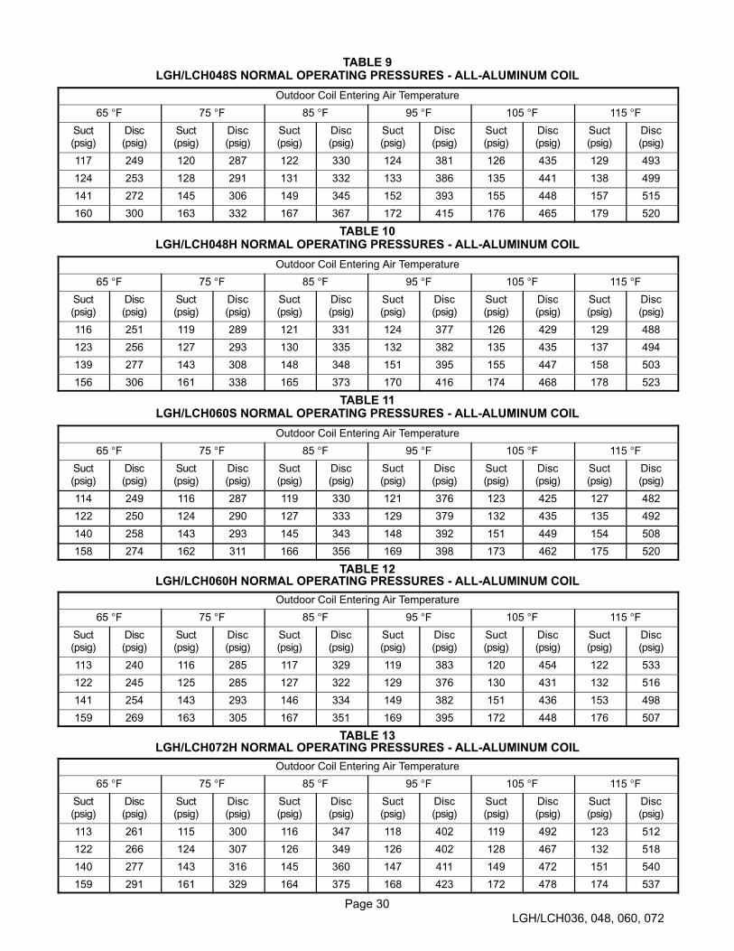
Page 30
LGH/LCH036, 048, 060, 072
TABLE 9LGH/LCH048S NORMAL OPERATING PRESSURES - ALL-ALUMINUM COIL
Outdoor Coil Entering Air Temperature
65 F 75 F 85 F 95 F 105 F 115 F
Suct(psig)
Disc(psig)
Suct(psig)
Disc(psig)
Suct(psig)
Disc(psig)
Suct(psig)
Disc(psig)
Suct(psig)
Disc(psig)
Suct(psig)
Disc(psig)
117 249 120 287 122 330 124 381 126 435 129 493
124 253 128 291 131 332 133 386 135 441 138 499
141 272 145 306 149 345 152 393 155 448 157 515
160 300 163 332 167 367 172 415 176 465 179 520
TABLE 10LGH/LCH048H NORMAL OPERATING PRESSURES - ALL-ALUMINUM COIL
Outdoor Coil Entering Air Temperature
65 F 75 F 85 F 95 F 105 F 115 F
Suct(psig)
Disc(psig)
Suct(psig)
Disc(psig)
Suct(psig)
Disc(psig)
Suct(psig)
Disc(psig)
Suct(psig)
Disc(psig)
Suct(psig)
Disc(psig)
116 251 119 289 121 331 124 377 126 429 129 488
123 256 127 293 130 335 132 382 135 435 137 494
139 277 143 308 148 348 151 395 155 447 158 503
156 306 161 338 165 373 170 416 174 468 178 523
TABLE 11LGH/LCH060S NORMAL OPERATING PRESSURES - ALL-ALUMINUM COIL
Outdoor Coil Entering Air Temperature
65 F 75 F 85 F 95 F 105 F 115 F
Suct(psig)
Disc(psig)
Suct(psig)
Disc(psig)
Suct(psig)
Disc(psig)
Suct(psig)
Disc(psig)
Suct(psig)
Disc(psig)
Suct(psig)
Disc(psig)
114 249 116 287 119 330 121 376 123 425 127 482
122 250 124 290 127 333 129 379 132 435 135 492
140 258 143 293 145 343 148 392 151 449 154 508
158 274 162 311 166 356 169 398 173 462 175 520
TABLE 12LGH/LCH060H NORMAL OPERATING PRESSURES - ALL-ALUMINUM COIL
Outdoor Coil Entering Air Temperature
65 F 75 F 85 F 95 F 105 F 115 F
Suct(psig)
Disc(psig)
Suct(psig)
Disc(psig)
Suct(psig)
Disc(psig)
Suct(psig)
Disc(psig)
Suct(psig)
Disc(psig)
Suct(psig)
Disc(psig)
113 240 116 285 117 329 119 383 120 454 122 533
122 245 125 285 127 322 129 376 130 431 132 516
141 254 143 293 146 334 149 382 151 436 153 498
159 269 163 305 167 351 169 395 172 448 176 507
TABLE 13LGH/LCH072H NORMAL OPERATING PRESSURES - ALL-ALUMINUM COIL
Outdoor Coil Entering Air Temperature
65 F 75 F 85 F 95 F 105 F 115 F
Suct(psig)
Disc(psig)
Suct(psig)
Disc(psig)
Suct(psig)
Disc(psig)
Suct(psig)
Disc(psig)
Suct(psig)
Disc(psig)
Suct(psig)
Disc(psig)
113 261 115 300 116 347 118 402 119 492 123 512
122 266 124 307 126 349 126 402 128 467 132 518
140 277 143 316 145 360 147 411 149 472 151 540
159 291 161 329 164 375 168 423 172 478 174 537

Page 31
LGH/LCH036, 048, 060, 072
LGH/LCH036S CHARGING CURVE - ALL-ALUMINUM COIL
60
70
80
90
100
110
120
130
110 120 130 140 150 160 170 180
Outdoor Temperature (°F)
Suction Pressure (psig)
105°
95°
115°
85°
75°
65°
60
70
80
90
100
110
120
130
110 120 130 140 150 160
Outdoor Temperature (°F)
170 180Suction Pressure (psig)
105°
95°
115°
85°
75°
65°
LGH/LCH036H CHARGING CURVE - ALL-ALUMINUM COIL

Page 32
LGH/LCH036, 048, 060, 072
LGH/LCH048S CHARGING CURVE - ALL-ALUMINUM COIL
Suction Pressure (psig)
60
70
80
90
100
110
120
130
110 120 130 140 150 160
Outdoor Temperature (°F)
170 180
105°
95°
115°
85°
75°
65°
LGH/LCH048H CHARGING CURVE - ALL-ALUMINUM COIL
Suction Pressure (psig)
60
70
80
90
100
110
120
130
110 120 130 140 150 160
Outdoor Temperature (°F)
170 180
105°
95°
115°
85°
75°
65°
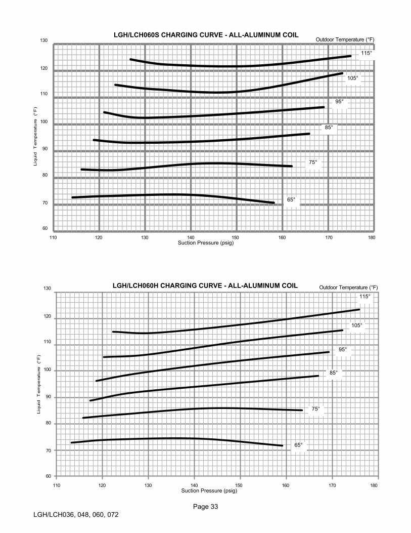
Page 33
LGH/LCH036, 048, 060, 072
LGH/LCH060S CHARGING CURVE - ALL-ALUMINUM COIL
60
70
80
90
100
110
120
130
110 120 130 140 150 160
Outdoor Temperature (°F)
170 180Suction Pressure (psig)
105°
95°
115°
85°
75°
65°
60
70
80
90
100
110
120
130
110 120 130 140 150 160
Outdoor Temperature (°F)
170 180Suction Pressure (psig)
105°
95°
115°
85°
75°
65°
LGH/LCH060H CHARGING CURVE - ALL-ALUMINUM COIL

Page 34
LGH/LCH036, 048, 060, 072
LGH/LCH072H CHARGING CURVE - ALL-ALUMINUM COIL
Suction Pressure (psig)
60
70
80
90
100
110
120
130
110 120 130 140 150 160
Outdoor Temperature (°F)
170 180
105°
95°
115°
85°
75°
65°
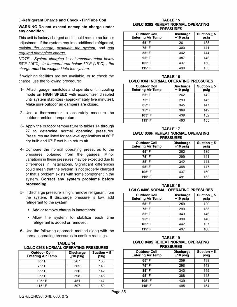
Page 35
LGH/LCH036, 048, 060, 072
D-Refrigerant Charge and Check - Fin/Tube Coil
WARNING-Do not exceed nameplate charge underany condition.
This unit is factory charged and should require no further
adjustment. If the system requires additional refrigerant,
reclaim the charge, evacuate the system, and add
required nameplate charge.
NOTE - System charging is not recommended below
60°F (15°C). In temperatures below 60°F (15°C) , the
charge must be weighed into the system.
If weighing facilities are not available, or to check the
charge, use the following procedure:
1- Attach gauge manifolds and operate unit in cooling
mode on HIGH SPEED with economizer disabled
until system stabilizes (approximately five minutes).
Make sure outdoor air dampers are closed.
2- Use a thermometer to accurately measure the
outdoor ambient temperature.
3- Apply the outdoor temperature to tables 14 through
27 to determine normal operating pressures.
Pressures are listed for sea level applications at 80°F
dry bulb and 67°F wet bulb return air.
4- Compare the normal operating pressures to the
pressures obtained from the gauges. Minor
variations in these pressures may be expected due to
differences in installations. Significant differences
could mean that the system is not properly charged
or that a problem exists with some component in the
system. Correct any system problems before
proceeding.
5- If discharge pressure is high, remove refrigerant from
the system. If discharge pressure is low, add
refrigerant to the system.
� Add or remove charge in increments.
� Allow the system to stabilize each time
refrigerant is added or removed.
6- Use the following approach method along with the
normal operating pressures to confirm readings.
TABLE 14LG/LC 036S NORMAL OPERATING PRESSURES
Outdoor CoilEntering Air Temp
Discharge+10 psig
Suction + 5psig
65� F 267 138
75� F 305 140
85� F 350 142
95� F 398 146
105� F 451 147
115� F 507 150
TABLE 15LG/LC 036S REHEAT NORMAL OPERATING
PRESSURES
Outdoor CoilEntering Air Temp
Discharge+10 psig
Suction + 5psig
65� F 261 138
75� F 300 141
85� F 342 144
95� F 387 148
105� F 437 150
115� F 490 153
TABLE 16LG/LC 036H NORMAL OPERATING PRESSURES
Outdoor CoilEntering Air Temp
Discharge+10 psig
Suction + 5psig
65� F 262 142
75� F 293 145
85� F 345 147
95� F 389 149
105� F 439 152
115� F 493 155
TABLE 17LG/LC 036H REHEAT NORMAL OPERATING
PRESSURES
Outdoor CoilEntering Air Temp
Discharge+10 psig
Suction + 5psig
65� F 262 139
75� F 299 141
85� F 342 144
95� F 388 147
105� F 437 150
115� F 491 153
TABLE 18LG/LC 048S NORMAL OPERATING PRESSURES
Outdoor CoilEntering Air Temp
Discharge+10 psig
Suction + 5psig
65� F 259 129
75� F 299 138
85� F 343 146
95� F 390 148
105� F 442 157
115� F 497 160
TABLE 19LG/LC 048S REHEAT NORMAL OPERATING
PRESSURES
Outdoor CoilEntering Air Temp
Discharge+10 psig
Suction + 5psig
65� F 259 139
75� F 298 143
85� F 340 145
95� F 388 148
105� F 439 151
115� F 495 154
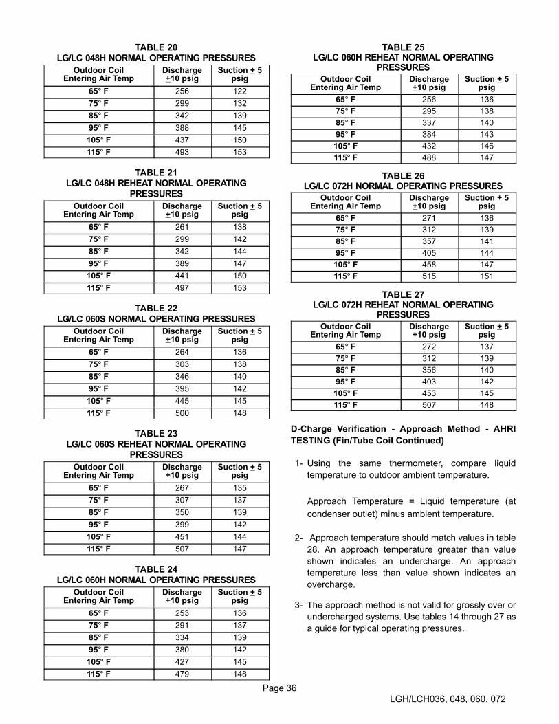
Page 36
LGH/LCH036, 048, 060, 072
TABLE 20LG/LC 048H NORMAL OPERATING PRESSURES
Outdoor CoilEntering Air Temp
Discharge+10 psig
Suction + 5psig
65� F 256 122
75� F 299 132
85� F 342 139
95� F 388 145
105� F 437 150
115� F 493 153
TABLE 21LG/LC 048H REHEAT NORMAL OPERATING
PRESSURES
Outdoor CoilEntering Air Temp
Discharge+10 psig
Suction + 5psig
65� F 261 138
75� F 299 142
85� F 342 144
95� F 389 147
105� F 441 150
115� F 497 153
TABLE 22LG/LC 060S NORMAL OPERATING PRESSURES
Outdoor CoilEntering Air Temp
Discharge+10 psig
Suction + 5psig
65� F 264 136
75� F 303 138
85� F 346 140
95� F 395 142
105� F 445 145
115� F 500 148
TABLE 23LG/LC 060S REHEAT NORMAL OPERATING
PRESSURES
Outdoor CoilEntering Air Temp
Discharge+10 psig
Suction + 5psig
65� F 267 135
75� F 307 137
85� F 350 139
95� F 399 142
105� F 451 144
115� F 507 147
TABLE 24LG/LC 060H NORMAL OPERATING PRESSURES
Outdoor CoilEntering Air Temp
Discharge+10 psig
Suction + 5psig
65� F 253 136
75� F 291 137
85� F 334 139
95� F 380 142
105� F 427 145
115� F 479 148
TABLE 25LG/LC 060H REHEAT NORMAL OPERATING
PRESSURES
Outdoor CoilEntering Air Temp
Discharge+10 psig
Suction + 5psig
65� F 256 136
75� F 295 138
85� F 337 140
95� F 384 143
105� F 432 146
115� F 488 147
TABLE 26LG/LC 072H NORMAL OPERATING PRESSURES
Outdoor CoilEntering Air Temp
Discharge+10 psig
Suction + 5psig
65� F 271 136
75� F 312 139
85� F 357 141
95� F 405 144
105� F 458 147
115� F 515 151
TABLE 27LG/LC 072H REHEAT NORMAL OPERATING
PRESSURES
Outdoor CoilEntering Air Temp
Discharge+10 psig
Suction + 5psig
65� F 272 137
75� F 312 139
85� F 356 140
95� F 403 142
105� F 453 145
115� F 507 148
D-Charge Verification - Approach Method - AHRI
TESTING (Fin/Tube Coil Continued)
1- Using the same thermometer, compare liquid
temperature to outdoor ambient temperature.
Approach Temperature = Liquid temperature (at
condenser outlet) minus ambient temperature.
2- Approach temperature should match values in table
28. An approach temperature greater than value
shown indicates an undercharge. An approach
temperature less than value shown indicates an
overcharge.
3- The approach method is not valid for grossly over or
undercharged systems. Use tables 14 through 27 as
a guide for typical operating pressures.

Page 37
LGH/LCH036, 048, 060, 072
TABLE 28APPROACH TEMPERATURE
LGH/LCH Unit Liquid Temp. Minus Ambient Temp.
036S & H Std.036S & H Reheat048H Std.060S & H Reheat060H Std.072H Std.
6°F + 1 (3.3°C + 0.5)
048H Reheat072H Reheat
7°F + 1 (3.9°C + 0.5)
048S Std.060S Std.
8°F + 1 (4.4°C + 0.5)
048S Reheat 9°F + 1 (5.0°C + 0.5)
E-Compressor Controls
See unit wiring diagram to determine which controls are
used on each unit. Optional controls are identified on
wiring diagrams by arrows at junction points.
1- High Pressure Switch (S4)
The compressor circuit is protected by a high
pressure switch which opens at 640 psig + 10 psig
(4413 kPa + 70 kPa) and automatically resets at 475
psig + 20 psig (3275kPa + 138 kPa).
2- Low Pressure Switch (S87)
The compressor circuit is protected by a loss of
charge switch. Switch opens at 40 psig + 5 psig (276
+ 34 kPa) and automatically resets at 90 psig + 5
psig (621 kPa + 34 kPa).
3- Freezestat (S49)
The compressor is protected by a freezestat located
on the indoor coil. The freezestat opens at 29�F+3
(-2�C+2) and closes at 58�F+4 (14�C+2).
4- Compressor Crankcase Heater (HR1)
Crankcase heater must be energized at all times to
prevent compressor damage due to refrigerant
migration. Energize crankcase heater 24 hours before
unit start-up by setting thermostat so that there is no
cooling demand (to prevent compressor from cycling)
and apply power to unit.
5- Low Ambient Pressure Switch (S11)
Switch maintains adequate discharge pressure by
de-energizing condenser fan when liquid pressure
falls below 240 psig +10 (1655 kPa+69). S11 is
installed in the liquid line. Switch closes to energize
condenser fan when pressure rises to 450 psig +10
(3103kPa + 69).
6- Discharge Line Thermostat (S40)
3 through 5 Ton Units Only
Switch opens when discharge line temperature
reaches 94�F+5 (34�C+3) and closes when
temperature falls below 74�F+5 (23�C+3). Prevents
crankcase heater operation in warm weather.
7- High Ambient Pressure Switch (S16)
Switch improves high ambient operation by
activating the TXV assist circuit. Switch closes at
550psig + 10 (3792kPa + 70kPa) and automatically
resets at 400 PSIG (2758kPa + 70kPa).
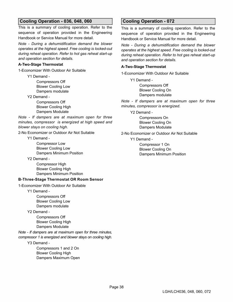
Page 38
LGH/LCH036, 048, 060, 072
Cooling Operation - 036, 048, 060
This is a summary of cooling operation. Refer to the
sequence of operation provided in the Engineering
Handbook or Service Manual for more detail.
Note - During a dehumidification demand the blower
operates at the highest speed. Free cooling is locked-out
during reheat operation. Refer to hot gas reheat start-up
and operation section for details.
A-Two-Stage Thermostat
1-Economizer With Outdoor Air Suitable
Y1 Demand -
Compressors Off
Blower Cooling Low
Dampers modulate
Y2 Demand -
Compressors Off
Blower Cooling High
Dampers Modulate
Note - If dampers are at maximum open for three
minutes, compressor is energized at high speed and
blower stays on cooling high.
2-No Economizer or Outdoor Air Not Suitable
Y1 Demand -
Compressor Low
Blower Cooling Low
Dampers Minimum Position
Y2 Demand -
Compressor High
Blower Cooling High
Dampers Minimum Position
B-Three-Stage Thermostat OR Room Sensor
1-Economizer With Outdoor Air Suitable
Y1 Demand -
Compressors Off
Blower Cooling Low
Dampers modulate
Y2 Demand -
Compressors Off
Blower Cooling High
Dampers Modulate
Note - If dampers are at maximum open for three minutes,
compressor 1 is energized and blower stays on cooling high.
Y3 Demand -
Compressors 1 and 2 On
Blower Cooling High
Dampers Maximum Open
Cooling Operation - 072
This is a summary of cooling operation. Refer to the
sequence of operation provided in the Engineering
Handbook or Service Manual for more detail.
Note - During a dehumidification demand the blower
operates at the highest speed. Free cooling is locked-out
during reheat operation. Refer to hot gas reheat start-up
and operation section for details.
A-Two-Stage Thermostat
1-Economizer With Outdoor Air Suitable
Y1 Demand -
Compressors Off
Blower Cooling On
Dampers modulate
Note - If dampers are at maximum open for three
minutes, compressor is energized.
Y2 Demand -
Compressors On
Blower Cooling On
Dampers Modulate
2-No Economizer or Outdoor Air Not Suitable
Y1 Demand -
Compressor 1 On
Blower Cooling On
Dampers Minimum Position

Page 39
LGH/LCH036, 048, 060, 072
Gas Heat Start-Up (Gas Units)
FOR YOUR SAFETY READ BEFORE LIGHTING
WARNINGElectric shock hazard. Can cause injuryor death. Do not use this unit if any parthas been under water. Immediately calla qualified service technician to inspectthe unit and to replace any part of thecontrol system and any gas controlwhich has been under water.
WARNINGDanger of explosion. Can cause injuryor product or property damage. If overheating occurs or if gas supply fails toshut off, shut off the manual gas valveto the appliance before shutting offelectrical supply.
WARNINGElectric shock hazard. Can causeinjury or death. Before attempting toperform any service or maintenance,turn the electrical power to unit OFF atdisconnect switch(es). Unit may havemultiple power supplies.
WARNINGSMOKE POTENTIAL
The heat exchanger in this unit could be a source ofsmoke on initial firing. Take precautions with respect to building occupants and property. Vent initial supply air outside when possible.
BEFORE LIGHTING smell all around the appliance area
for gas. Be sure to smell next to the floor because some
gas is heavier than air and will settle on the floor.
The gas valve may be equipped with either a gas control
lever or gas control knob. Use only your hand to push
the lever or turn the gas control knob. Never use tools. If
the the lever will not move or the knob will not push in or
turn by hand, do not try to repair it. Call a qualified
service technician. Force or attempted repair may
result in a fire or explosion.
WARNINGDanger of explosion. Can cause injury ordeath. Do not attempt to light manually.Unit has a direct spark ignition system.
This unit is equipped with an automatic spark ignition
system. There is no pilot. In case of a safety shutdown,
move thermostat switch to OFF and return the thermostat
switch to HEAT to reset ignition control.
A-Placing Unit In Operation
WARNINGDanger of explosion and fire. Can causeinjury or product or property damage.You must follow these instructionsexactly.
Gas Valve Operation (figure 25 and 26)
1- Set thermostat to lowest setting.
2- Turn off all electrical power to appliance.
3- This appliance is equipped with an ignition device
which automatically lights the burner. Do not try to
light the burner by hand.
4- Open or remove the control access panel.
MANIFOLDPRESSURE
OUTLET
Gas valve switch shown in ON position.
INLETPRESSURE
PORT
MANIFOLDPRESSURE
ADJUSTMENTSCREW
FIGURE 25
HONEYWELL VR8215S GAS VALVE
Single-Stage
WHITE RODGERS 36J54 GAS VALVE
Two-Stage
Gas valve switch is shown in OFF position.
FIGURE 26
LOW FIREADJUSTMENT
HIGH FIREADJUSTMENT
INLETPRESSURE
TAP
MANIFOLDPRESSURE TAP
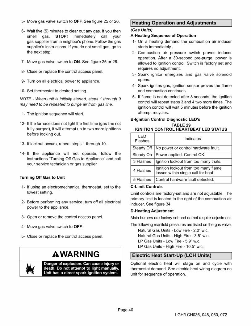
Page 40
LGH/LCH036, 048, 060, 072
5- Move gas valve switch to OFF. See figure 25 or 26.
6- Wait five (5) minutes to clear out any gas. If you then
smell gas, STOP! Immediately call your
gas supplier from a neighbor's phone. Follow the gas
supplier's instructions. If you do not smell gas, go to
the next step.
7- Move gas valve switch to ON. See figure 25 or 26.
8- Close or replace the control access panel.
9- Turn on all electrical power to appliance.
10- Set thermostat to desired setting.
NOTE - When unit is initially started, steps 1 through 9
may need to be repeated to purge air from gas line.
11- The ignition sequence will start.
12- If the furnace does not light the first time (gas line not
fully purged), it will attempt up to two more ignitions
before locking out.
13- If lockout occurs, repeat steps 1 through 10.
14- If the appliance will not operate, follow the
instructions “Turning Off Gas to Appliance” and call
your service technician or gas supplier.
Turning Off Gas to Unit
1- If using an electromechanical thermostat, set to the
lowest setting.
2- Before performing any service, turn off all electrical
power to the appliance.
3- Open or remove the control access panel.
4- Move gas valve switch to OFF.
5- Close or replace the control access panel.
WARNINGDanger of explosion. Can cause injury ordeath. Do not attempt to light manually.Unit has a direct spark ignition system.
Heating Operation and Adjustments
(Gas Units)
A-Heating Sequence of Operation
1- On a heating demand the combustion air inducer
starts immediately.
2- Combustion air pressure switch proves inducer
operation. After a 30-second pre-purge, power is
allowed to ignition control. Switch is factory set and
requires no adjustment.
3- Spark ignitor energizes and gas valve solenoid
opens.
4- Spark ignites gas, ignition sensor proves the flame
and combustion continues.
5- If flame is not detected after 8 seconds, the ignition
control will repeat steps 3 and 4 two more times. The
ignition control will wait 5 minutes before the ignition
attempt recycles.
B-Ignition Control Diagnostic LED's
TABLE 29IGNITION CONTROL HEARTBEAT LED STATUS
LEDFlashes
Indicates
Steady Off No power or control hardware fault.
Steady On Power applied. Control OK.
3 Flashes Ignition lockout from too many trials.
4 FlashesIgnition lockout from too many flamelosses within single call for heat.
5 Flashes Control hardware fault detected.
C-Limit Controls
Limit controls are factory-set and are not adjustable. The
primary limit is located to the right of the combustion air
inducer. See figure 34.
D-Heating Adjustment
Main burners are factory-set and do not require adjustment.
The following manifold pressures are listed on the gas valve.
Natural Gas Units - Low Fire - 2.0” w.c.
Natural Gas Units - High Fire - 3.5” w.c.
LP Gas Units - Low Fire - 5.9” w.c.
LP Gas Units - High Fire - 10.5” w.c.
Electric Heat Start-Up (LCH Units)
Optional electric heat will stage on and cycle with
thermostat demand. See electric heat wiring diagram on
unit for sequence of operation.

Page 41
LGH/LCH036, 048, 060, 072
Advanced Air Flow Control Start-Up
Three-, four- and five-ton units equipped with a direct
drive blower and optional economizer allows the installer
to directly enter the design specified supply air (blower)
and outdoor air volume (economizer minimum position)
parameters without the need to manually take
measurements and adjust settings. The system monitors
supply air volume and outside air volume and also has
customizable diagnostics.
Note - Unit Controller configuration I.D. 1 character 7 is
factory-set to either S or L for the unit to operate in
Advanced Air Flow Control mode. When character 7 is set
to N or U, the Unit Controller will stage the indoor blower
speed but it won't control the damper minimum position.
The economizer is equipped with a PT5 pressure
transducer which provides feedback for damper
minimum position. See figure 27 for PT5 location. Refer to
the economizer installation instructions and Unit
Controller manual for additional economizer set-up.
Note - Modulation of dampers for free cooling does not
change.
ADesign Specifications
Use table 30 to fill in the field-provided,
design-specified supply air CFM and minimum required
outdoor/fresh air CFM.
TABLE 30
FIELD-PROVIDED DESIGN SPECIFICATIONS
Supply Air CFM
Heating CFM
Cooling High CFM
Cooling Low CFM
Ventilation CFM
Economizer Minimum Position
Outdoor Airflow CFM
BEnter Supply Air CFM Into Unit Controller
Use the following menu path to enter each supply air CFM
into the Unit Controller. Make sure supply air CFM is
within limitations shown in table 31. Refer to the Unit
Controller manual provided with unit.
SETTING > RTU OPTIONS > BLOWER > SPEEDS
In the SPEEDS submenu, enter CFM values for HEAT,
COOLING HIGH, COOLING LOW and VENTILATION.
Use the down, up and save push buttons below the
display to enter each value.
After the speed CFM are saved, the Unit Controller will
cycle to BLOWER CALIBRATION.
PT5 PRESSURE TRANSDUCER
PRESSURETRANSDUCER
FIGURE 27
ECONOMIZER
CAUTIONThe BLOWER CALIBRATION process starts the in
door blower at operational speeds and moves the
economizer damper blades. Before starting this pro
cess, replace any access panels and close all unit
doors except compressor compartment door.
Blower calibration is required only on units that are newly
installed or if there is a change in the duct work or air filters
after installation. After the new CFM values are entered,
use the down and up arrow buttons to select START
CALIBRATION. Push SAVE to start calibration. The
blower calibration status is displayed as a % complete.
Upon successful completion, the Unit Controller will
display CALIBRATION SUCCESS and go back to the
blower calibration screen. Press the MAIN MENU button
to go to the main menu and press the BACK button to go
to the status screen.
If only the CFM values are updated, use the down and up
arrow buttons to select “CALIBRATION DONE”. Push
SAVE to enter the updated values. This selection will not
initiate calibration, resulting in less setup time. Press the
MAIN MENU button to go to the main menu and press the
BACK button to go to the status screen.

Page 42
LGH/LCH036, 048, 060, 072
CEnter Outdoor Airflow Design Specifications Into
Unit Controller
Use the following menu path to enter the outdoor airflow
CFM (replaces minimum damper position set point) into
the Unit Controller. Make sure outdoor airflow CFM is
within limitations shown in table 31. Refer to the Unit
Controller manual provided with unit.
SETTINGS > RTU OPTIONS > DAMPER
Press the SAVE button to cycle through the sub-menu
until the OUTDOOR AIRFLOW input screen is displayed.
Enter the value and press SAVE.
Press the MAIN MENU button to go to the main menu and
press the BACK button to go to the status screen.
DOperation
1- After calibration, the indoor blower will supply the
CFM specified based on the thermostat demand
signal received by the Unit Controller:
G – Ventilation CFM
W – Heating CFM
Y1 – Cooling Low CFM
Y2 – Cooling High CFM
2- The Unit Controller, using input from PT5 and the
entered outdoor air flow CFM, will open the fresh
air dampers to minimum position. In addition, the
Unit Controller must have an occupied (OCP)
thermostat demand.
TABLE 31
MINIMUM / MAXIMUM CFM
LGH/LCH036-060 Unit Parameter Settings
Parameter NameLCH/LGH Default Factory Settings
036H4E 048H4E 060H4E
SETUP > TEST & BALANCE > BLOWER
COOLING HI SPEED / HEATING MAXIMUM (480 CFM/TON) 1440 1920 2400
COOLING HI SPEED MINIMUM (280 CFM/TON) 840 1120 1400
COOLING LOW SPEED MINIMUM (220 CFM/TON) 660 880 1100
GAS HEAT - STANDARD - MINIMUM CFM 970 970 970
GAS HEAT - MEDIUM - MINIMUM CFM 1120 1120 1120
GAS HEAT - HIGH - MINIMUM CFM 1310 1310 1310
ELECTRIC HEAT - MINIMUM CFM 1080 1280 1600
VENTILATION MINIMUM (150 CFM/TON) 450 600 750
SETUP > TEST & BALANCE > DAMPER
OUTDOOR AIRFLOW CFM MAXIMUM CFM 450 600 750
SETTINGS > RTU OPTIONS > EDIT PARAMETER = 12In order for the SMOKE CFM change to take effect, go to SETUP > TEST & BALANCE > BLOWER and run the the wizard. Performing thistask will recalculate the output to the desired CFM. No adjustments are required during this procedure.
MSAV SMOKE CFM MAXIMUM 1440 1920 2400
Installer: Configuration ID 1, position 7 needs to be set to either S or L. Circle applicable unit model number and record any CFM changes under
“Field Set CFM Value” column. Settings need to be recorded by installer for use when Unit Controller is replaced or reprogrammed.
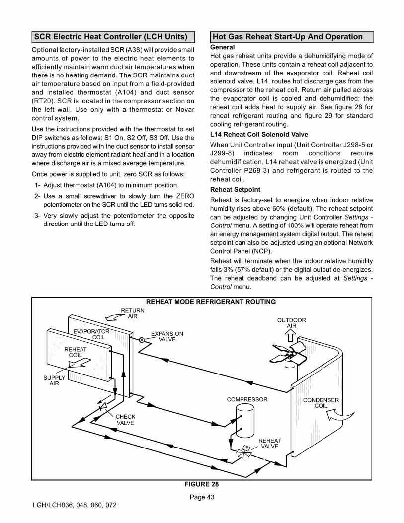
Page 43
LGH/LCH036, 048, 060, 072
SCR Electric Heat Controller (LCH Units)
Optional factory-installed SCR (A38) will provide small
amounts of power to the electric heat elements to
efficiently maintain warm duct air temperatures when
there is no heating demand. The SCR maintains duct
air temperature based on input from a field-provided
and installed thermostat (A104) and duct sensor
(RT20). SCR is located in the compressor section on
the left wall. Use only with a thermostat or Novar
control system.
Use the instructions provided with the thermostat to set
DIP switches as follows: S1 On, S2 Off, S3 Off. Use the
instructions provided with the duct sensor to install sensor
away from electric element radiant heat and in a location
where discharge air is a mixed average temperature.
Once power is supplied to unit, zero SCR as follows:
1- Adjust thermostat (A104) to minimum position.
2- Use a small screwdriver to slowly turn the ZERO
potentiometer on the SCR until the LED turns solid red.
3- Very slowly adjust the potentiometer the opposite
direction until the LED turns off.
Hot Gas Reheat Start-Up And Operation
General
Hot gas reheat units provide a dehumidifying mode of
operation. These units contain a reheat coil adjacent to
and downstream of the evaporator coil. Reheat coil
solenoid valve, L14, routes hot discharge gas from the
compressor to the reheat coil. Return air pulled across
the evaporator coil is cooled and dehumidified; the
reheat coil adds heat to supply air. See figure 28 for
reheat refrigerant routing and figure 29 for standard
cooling refrigerant routing.
L14 Reheat Coil Solenoid Valve
When Unit Controller input (Unit Controller J298-5 or
J299-8) indicates room conditions require
dehumidification, L14 reheat valve is energized (Unit
Controller P269-3) and refrigerant is routed to the
reheat coil.
Reheat Setpoint
Reheat is factory-set to energize when indoor relative
humidity rises above 60% (default). The reheat setpoint
can be adjusted by changing Unit Controller Settings -
Control menu. A setting of 100% will operate reheat from
an energy management system digital output. The reheat
setpoint can also be adjusted using an optional Network
Control Panel (NCP).
Reheat will terminate when the indoor relative humidity
falls 3% (57% default) or the digital output de-energizes.
The reheat deadband can be adjusted at Settings -
Control menu.
REHEAT MODE REFRIGERANT ROUTING
REHEATCOIL
EVAPORATOR
REHEATVALVE
RETURNAIR
CONDENSERCOIL
OUTDOORAIR
COMPRESSOR
SUPPLYAIR
CHECKVALVE
EXPANSIONVALVE
FIGURE 28
COIL
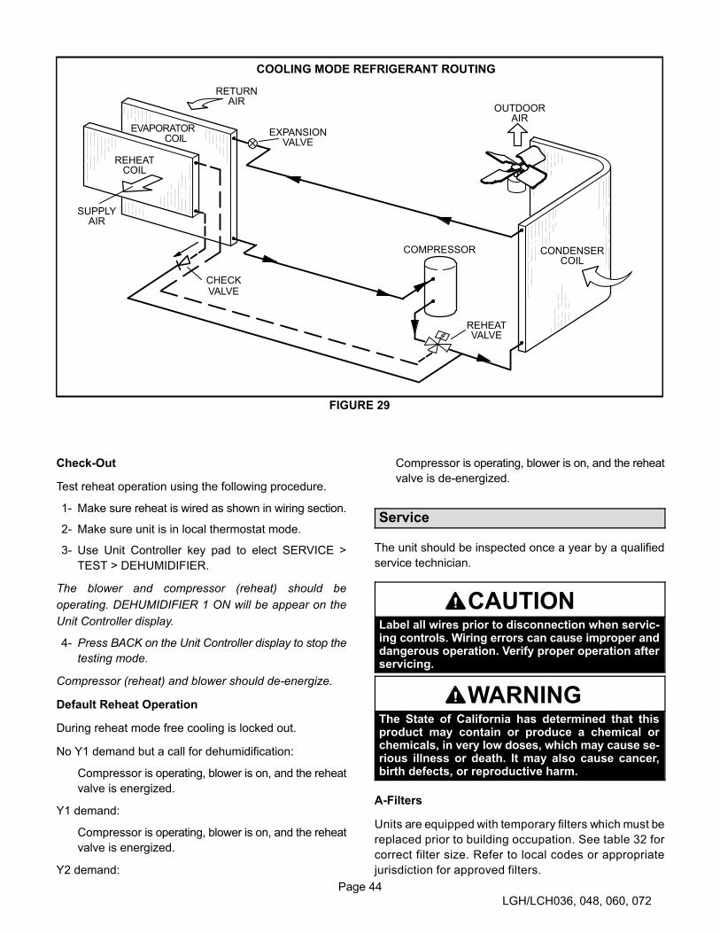
Page 44
LGH/LCH036, 048, 060, 072
COOLING MODE REFRIGERANT ROUTING
REHEATCOIL
EVAPORATOR
REHEATVALVE
RETURNAIR
CONDENSERCOIL
OUTDOORAIR
COMPRESSOR
SUPPLYAIR
CHECKVALVE
EXPANSIONVALVE
FIGURE 29
COIL
Check-Out
Test reheat operation using the following procedure.
1- Make sure reheat is wired as shown in wiring section.
2- Make sure unit is in local thermostat mode.
3- Use Unit Controller key pad to elect SERVICE >
TEST > DEHUMIDIFIER.
The blower and compressor (reheat) should be
operating. DEHUMIDIFIER 1 ON will be appear on the
Unit Controller display.
4- Press BACK on the Unit Controller display to stop the
testing mode.
Compressor (reheat) and blower should de-energize.
Default Reheat Operation
During reheat mode free cooling is locked out.
No Y1 demand but a call for dehumidification:
Compressor is operating, blower is on, and the reheat
valve is energized.
Y1 demand:
Compressor is operating, blower is on, and the reheat
valve is energized.
Y2 demand:
Compressor is operating, blower is on, and the reheat
valve is de-energized.
Service
The unit should be inspected once a year by a qualified
service technician.
CAUTIONLabel all wires prior to disconnection when servicing controls. Wiring errors can cause improper anddangerous operation. Verify proper operation afterservicing.
WARNINGThe State of California has determined that thisproduct may contain or produce a chemical orchemicals, in very low doses, which may cause serious illness or death. It may also cause cancer,birth defects, or reproductive harm.
A-Filters
Units are equipped with temporary filters which must be
replaced prior to building occupation. See table 32 for
correct filter size. Refer to local codes or appropriate
jurisdiction for approved filters.
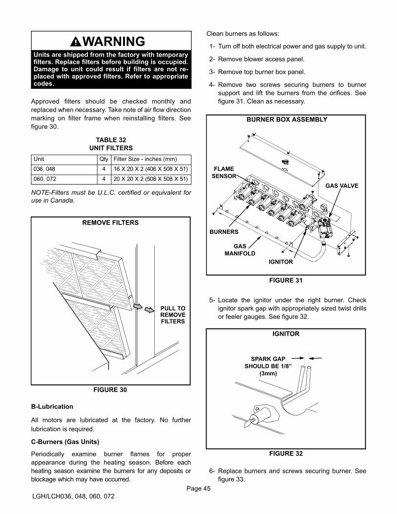
Page 45
LGH/LCH036, 048, 060, 072
WARNINGUnits are shipped from the factory with temporaryfilters. Replace filters before building is occupied.Damage to unit could result if filters are not replaced with approved filters. Refer to appropriatecodes.
Approved filters should be checked monthly and
replaced when necessary. Take note of air flow direction
marking on filter frame when reinstalling filters. See
figure 30.
TABLE 32
UNIT FILTERS
Unit Qty Filter Size - inches (mm)
036, 048 4 16 X 20 X 2 (406 X 508 X 51)
060, 072 4 20 X 20 X 2 (508 X 508 X 51)
NOTE-Filters must be U.L.C. certified or equivalent for
use in Canada.
FIGURE 30
REMOVE FILTERS
PULL TOREMOVEFILTERS
B-Lubrication
All motors are lubricated at the factory. No further
lubrication is required.
C-Burners (Gas Units)
Periodically examine burner flames for proper
appearance during the heating season. Before each
heating season examine the burners for any deposits or
blockage which may have occurred.
Clean burners as follows:
1- Turn off both electrical power and gas supply to unit.
2- Remove blower access panel.
3- Remove top burner box panel.
4- Remove two screws securing burners to burner
support and lift the burners from the orifices. See
figure 31. Clean as necessary.
FIGURE 31
BURNER BOX ASSEMBLY
GAS VALVE
GAS
MANIFOLD
FLAME
SENSOR
BURNERS
IGNITOR
5- Locate the ignitor under the right burner. Check
ignitor spark gap with appropriately sized twist drills
or feeler gauges. See figure 32.
FIGURE 32
IGNITOR
SPARK GAP
SHOULD BE 1/8”
(3mm)
6- Replace burners and screws securing burner. See
figure 33.
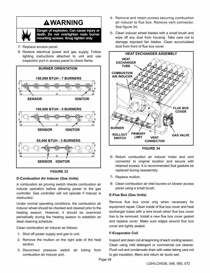
Page 46
LGH/LCH036, 048, 060, 072
WARNINGDanger of explosion. Can cause injury ordeath. Do not overtighten main burnermounting screws. Snug tighten only.
7- Replace access panel.
8- Restore electrical power and gas supply. Follow
lighting instructions attached to unit and use
inspection port in access panel to check flame.
FIGURE 33
BURNER ORIENTATION
150,000 BTUH - 7 BURNERS
108,000 BTUH - 5 BURNERS
65,000 BTUH - 3 BURNERS
SENSOR IGNITOR
SENSOR IGNITOR
SENSOR IGNITOR
D-Combustion Air Inducer (Gas Units)
A combustion air proving switch checks combustion air
inducer operation before allowing power to the gas
controller. Gas controller will not operate if inducer is
obstructed.
Under normal operating conditions, the combustion air
inducer wheel should be checked and cleaned prior to the
heating season. However, it should be examined
periodically during the heating season to establish an
ideal cleaning schedule.
Clean combustion air inducer as follows:
1- Shut off power supply and gas to unit.
2- Remove the mullion on the right side of the heat
section.
3- Disconnect pressure switch air tubing from
combustion air inducer port.
4- Remove and retain screws securing combustion
air inducer to flue box. Remove vent connector.
See figure 34.
5- Clean inducer wheel blades with a small brush and
wipe off any dust from housing. Take care not to
damage exposed fan blades. Clean accumulated
dust from front of flue box cover.
HEAT EXCHANGER ASSEMBLY
FIGURE 34
BURNER
COMBUSTIONAIR INDUCER
VENTCONNECTOR
GAS VALVE
HEATEXCHANGER
TUBE
PRIMARYLIMIT
ROLLOUTSWITCH
FLUE BOXCOVER
6- Return combustion air inducer motor and vent
connector to original location and secure with
retained screws. It is recommended that gaskets be
replaced during reassembly.
7- Replace mullion.
8- Clean combustion air inlet louvers on blower access
panel using a small brush.
E-Flue Box (Gas Units)
Remove flue box cover only when necessary for
equipment repair. Clean inside of flue box cover and heat
exchanger tubes with a wire brush when flue box cover
has to be removed. Install a new flue box cover gasket
and replace cover. Make sure edges around flue box
cover are tightly sealed.
F-Evaporator Coil
Inspect and clean coil at beginning of each cooling season.
Clean using mild detergent or commercial coil cleaner.
Flush coil and condensate drain with water taking care not
to get insulation, filters and return air ducts wet.
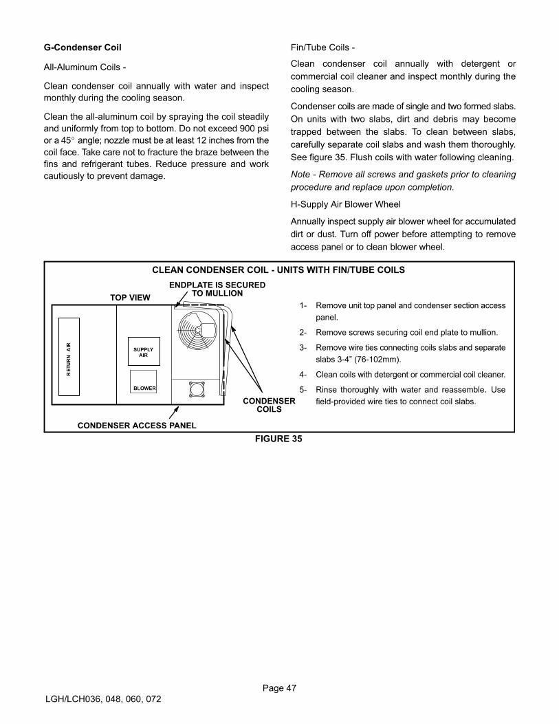
Page 47
LGH/LCH036, 048, 060, 072
G-Condenser Coil
All-Aluminum Coils -
Clean condenser coil annually with water and inspect
monthly during the cooling season.
Clean the all-aluminum coil by spraying the coil steadily
and uniformly from top to bottom. Do not exceed 900 psi
or a 45� angle; nozzle must be at least 12 inches from the
coil face. Take care not to fracture the braze between the
fins and refrigerant tubes. Reduce pressure and work
cautiously to prevent damage.
Fin/Tube Coils -
Clean condenser coil annually with detergent or
commercial coil cleaner and inspect monthly during the
cooling season.
Condenser coils are made of single and two formed slabs.
On units with two slabs, dirt and debris may become
trapped between the slabs. To clean between slabs,
carefully separate coil slabs and wash them thoroughly.
See figure 35. Flush coils with water following cleaning.
Note - Remove all screws and gaskets prior to cleaning
procedure and replace upon completion.
H-Supply Air Blower Wheel
Annually inspect supply air blower wheel for accumulated
dirt or dust. Turn off power before attempting to remove
access panel or to clean blower wheel.
TOP VIEW
CONDENSERCOILS
BLOWER
CONDENSER ACCESS PANEL
FIGURE 35
ENDPLATE IS SECUREDTO MULLION
1- Remove unit top panel and condenser section access
panel.
2- Remove screws securing coil end plate to mullion.
3- Remove wire ties connecting coils slabs and separate
slabs 3-4” (76-102mm).
4- Clean coils with detergent or commercial coil cleaner.
5- Rinse thoroughly with water and reassemble. Use
field-provided wire ties to connect coil slabs.
CLEAN CONDENSER COIL - UNITS WITH FIN/TUBE COILS
SUPPLYAIR
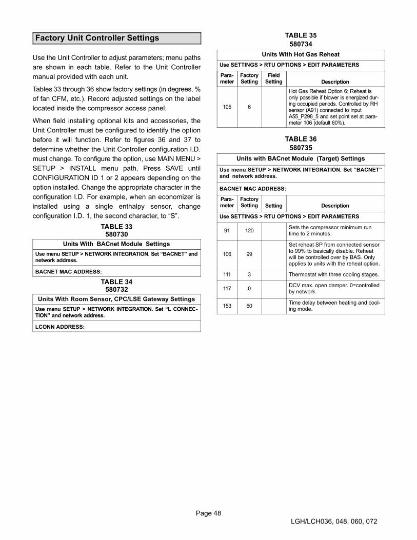
Page 48
LGH/LCH036, 048, 060, 072
Factory Unit Controller Settings
Use the Unit Controller to adjust parameters; menu paths
are shown in each table. Refer to the Unit Controller
manual provided with each unit.
Tables 33 through 36 show factory settings (in degrees, %
of fan CFM, etc.). Record adjusted settings on the label
located inside the compressor access panel.
When field installing optional kits and accessories, the
Unit Controller must be configured to identify the option
before it will function. Refer to figures 36 and 37 to
determine whether the Unit Controller configuration I.D.
must change. To configure the option, use MAIN MENU >
SETUP > INSTALL menu path. Press SAVE until
CONFIGURATION ID 1 or 2 appears depending on the
option installed. Change the appropriate character in the
configuration I.D. For example, when an economizer is
installed using a single enthalpy sensor, change
configuration I.D. 1, the second character, to “S”.
TABLE 33580730
Units With BACnet Module Settings
Use menu SETUP > NETWORK INTEGRATION. Set “BACNET” andnetwork address.
BACNET MAC ADDRESS:
TABLE 34580732
Units With Room Sensor, CPC/LSE Gateway Settings
Use menu SETUP > NETWORK INTEGRATION. Set “L CONNECTION” and network address.
LCONN ADDRESS:
TABLE 35
580734
Units With Hot Gas Reheat
Use SETTINGS > RTU OPTIONS > EDIT PARAMETERS
Parameter
FactorySetting
FieldSetting Description
105 6
Hot Gas Reheat Option 6: Reheat isonly possible if blower is energized during occupied periods. Controlled by RHsensor (A91) connected to inputA55_P298_5 and set point set at parameter 106 (default 60%).
TABLE 36
580735
Units with BACnet Module (Target) Settings
Use menu SETUP > NETWORK INTEGRATION. Set “BACNET”and network address.
BACNET MAC ADDRESS:
Parameter
FactorySetting Setting Description
Use SETTINGS > RTU OPTIONS > EDIT PARAMETERS
91 120Sets the compressor minimum runtime to 2 minutes.
106 99
Set reheat SP from connected sensorto 99% to basically disable. Reheatwill be controlled over by BAS. Onlyapplies to units with the reheat option.
111 3 Thermostat with three cooling stages.
117 0DCV max. open damper. 0=controlledby network.
153 60Time delay between heating and cooling mode.
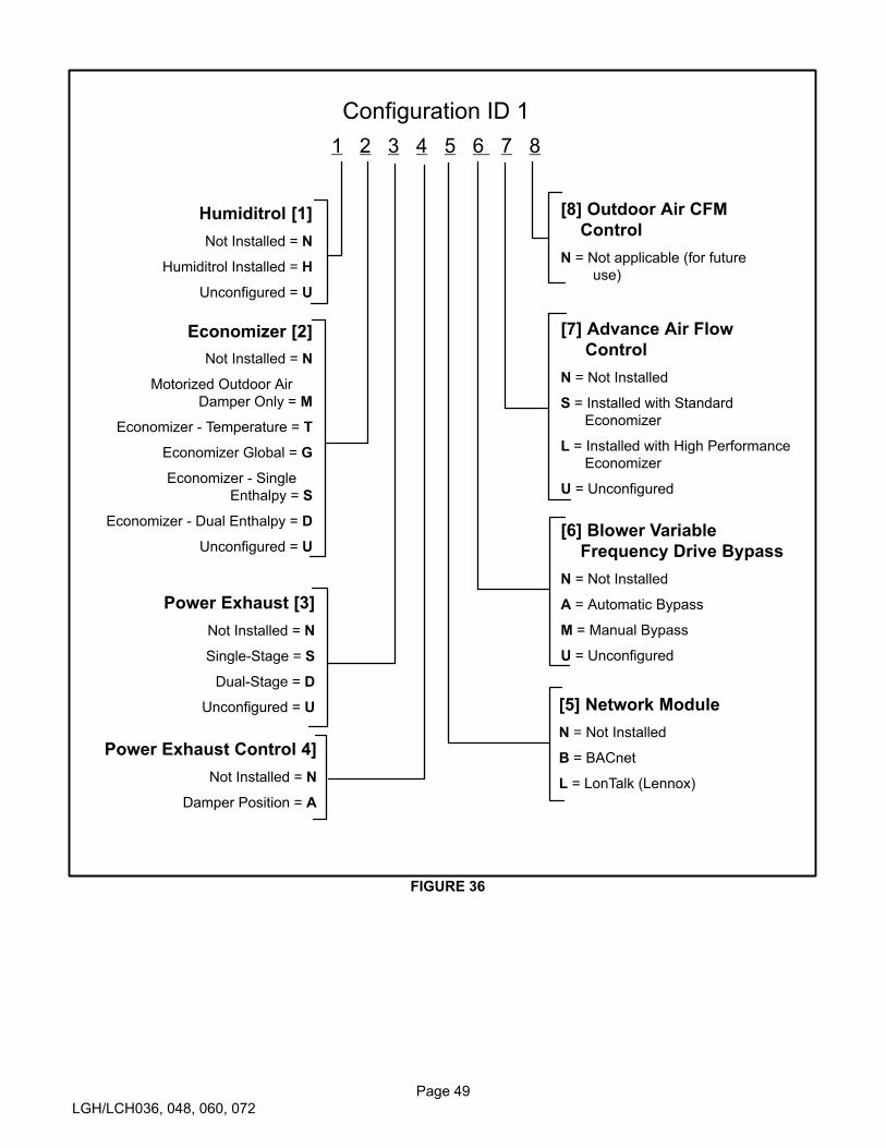
Page 49
LGH/LCH036, 048, 060, 072
Configuration ID 1
1 2 3 4 5 6 7 8
Humiditrol [1]
Not Installed = N
Humiditrol Installed = H
Unconfigured = U
Economizer [2]
Not Installed = N
Motorized Outdoor Air
Damper Only = M
Economizer - Temperature = T
Economizer Global = G
Economizer - Single
Enthalpy = S
Economizer - Dual Enthalpy = D
Unconfigured = U
Power Exhaust [3]
Not Installed = N
Single-Stage = S
Dual-Stage = D
Unconfigured = U
Power Exhaust Control 4]
Not Installed = N
Damper Position = A
[5] Network Module
N = Not Installed
B = BACnet
L = LonTalk (Lennox)
[6] Blower Variable
Frequency Drive Bypass
N = Not Installed
A = Automatic Bypass
M = Manual Bypass
U = Unconfigured
[7] Advance Air Flow
Control
N = Not Installed
S = Installed with Standard
Economizer
L = Installed with High Performance
Economizer
U = Unconfigured
[8] Outdoor Air CFM
Control
N = Not applicable (for future
use)
FIGURE 36

Page 50
LGH/LCH036, 048, 060, 072
Configuration ID 2
1 2 3 4 5 6 7 8 9
Not Installed = N
Installed on M3 = C
Installed on DDC
Controller = D
Dirty Filter Switch (S27) [2]
Not Installed = N
Installed on M3 = C
Not Installed = N
Installed on DI-2 = 2
Installed on DI-3 = 3
[5] Phase / Voltage Detection *
N = Not Installed
1 = Enabled Internal (Lennox)
2 = External (A42) Phase Detection
on DI-2
3 = External (A42) Phase Detection
on DI-3
N = Not Installed
Y = Installed
[8] Load Shedding
N = Not Installed
G = Global (P297 - pin 9)
L = Installed on DI-2
U = Installed on DI-3
[9] Electric Heat
(Field-Installed)
[1]Air Flow Proving Switch (S52)
[3]Overflow Switch
(S149 / S179)
[4]Motor Overload
Switch (S42)
Not Installed = N
Installed on DI-2 = 2
Installed on DI-3 = 3
[7] Zone Bypass Damper
N = Not Installed
Y = Installed
[6] Ultra Violet Lamp
N = Not Installed
Y = Installed
* When Phase / Voltage detection monitoring is enabled on a three-phase
system and configured incorrectly will result in the system going into de
mand hold status and then restart after three minutes.
FIGURE 37
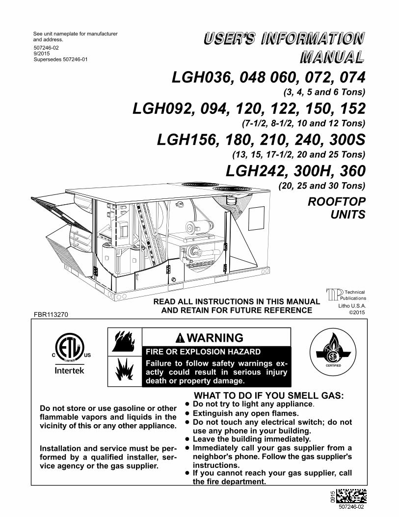
LGH036, 048 060, 072, 074
LGH092, 094, 120, 122, 150, 152
LGH156, 180, 210, 240, 300S
LGH242, 300H, 360
(3, 4, 5 and 6 Tons)
(7-1/2, 8‐1/2, 10 and 12 Tons)
(13, 15, 17-1/2, 20 and 25 Tons)
(20, 25 and 30 Tons)
2015
Litho U.S.A.
507246-029/2015Supersedes 507246-01
WHAT TO DO IF YOU SMELL GAS:
FIRE OR EXPLOSION HAZARD
Failure to follow safety warnings exactly could result in serious injurydeath or property damage.
WARNING
Do not store or use gasoline or otherflammable vapors and liquids in thevicinity of this or any other appliance.
Installation and service must be performed by a qualified installer, service agency or the gas supplier.
� Do not try to light any appliance.
� Do not touch any electrical switch; do notuse any phone in your building.
� Immediately call your gas supplier from aneighbor's phone. Follow the gas supplier'sinstructions.
� If you cannot reach your gas supplier, callthe fire department.
� Extinguish any open flames.
ROOFTOPUNITS
READ ALL INSTRUCTIONS IN THIS MANUALAND RETAIN FOR FUTURE REFERENCE
See unit nameplate for manufacturerand address.
FBR113270
� Leave the building immediately.
33
33
LLEENNOOXXNNLLEENNOOXXNN
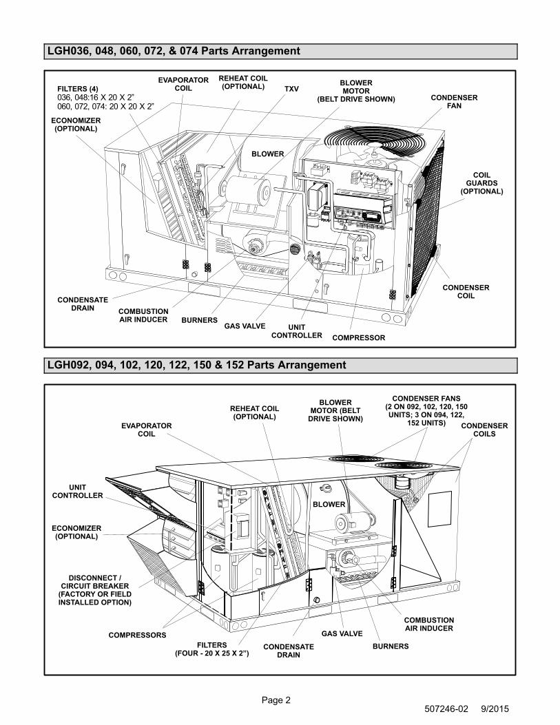
Page 2507246-02 9/2015
LGH036, 048, 060, 072, & 074 Parts Arrangement
EVAPORATORCOIL
CONDENSERFAN
CONDENSERCOIL
COMPRESSOR
CONDENSATEDRAIN
FILTERS (4)
036, 048:16 X 20 X 2”060, 072, 074: 20 X 20 X 2”
ECONOMIZER(OPTIONAL)
GAS VALVEBURNERS
COMBUSTIONAIR INDUCER
BLOWERMOTOR
(BELT DRIVE SHOWN)
TXV
UNITCONTROLLER
REHEAT COIL(OPTIONAL)
BLOWER
COILGUARDS
(OPTIONAL)
LGH092, 094, 102, 120, 122, 150 & 152 Parts Arrangement
UNITCONTROLLER
EVAPORATORCOIL
CONDENSER FANS(2 ON 092, 102, 120, 150UNITS; 3 ON 094, 122,
152 UNITS) CONDENSERCOILS
COMPRESSORS
CONDENSATEDRAIN
FILTERS(FOUR - 20 X 25 X 2”)
ECONOMIZER(OPTIONAL)
BLOWER
BLOWERMOTOR (BELT
DRIVE SHOWN)
GAS VALVE
BURNERS
COMBUSTIONAIR INDUCER
REHEAT COIL(OPTIONAL)
DISCONNECT /CIRCUIT BREAKER
(FACTORY OR FIELDINSTALLED OPTION)
33
33
LLEENNOOXXNNLLEENNOOXXNN
BLOWER
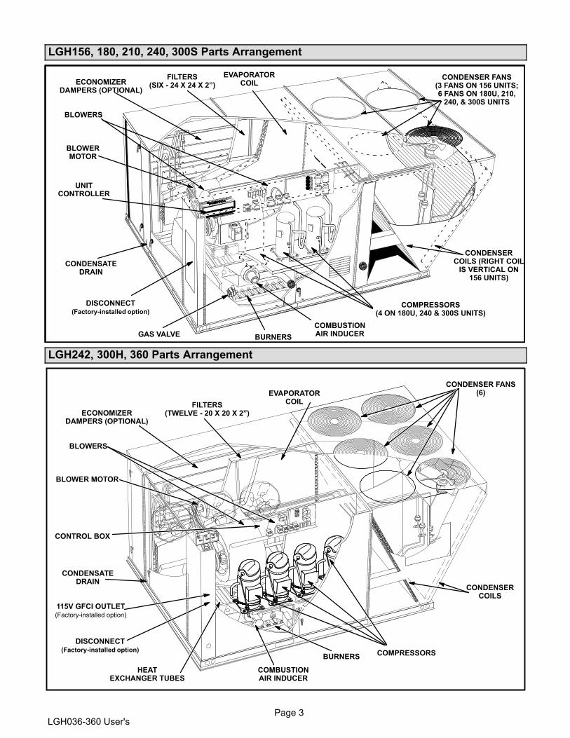
Page 3LGH036-360 User's
LGH156, 180, 210, 240, 300S Parts Arrangement
BLOWERS
EVAPORATORCOIL
COMBUSTIONAIR INDUCER
CONDENSER FANS(3 FANS ON 156 UNITS;6 FANS ON 180U, 210,
240, & 300S UNITS
CONDENSERCOILS (RIGHT COIL
IS VERTICAL ON156 UNITS)
COMPRESSORS(4 ON 180U, 240 & 300S UNITS)
GAS VALVE BURNERS
BLOWERMOTOR
CONDENSATEDRAIN
FILTERS(SIX - 24 X 24 X 2”)ECONOMIZER
DAMPERS (OPTIONAL)
UNITCONTROLLER
DISCONNECT(Factory-installed option)
LGH242, 300H, 360 Parts Arrangement
BURNERSCOMPRESSORS
COMBUSTIONAIR INDUCER
EVAPORATORCOIL
BLOWER MOTOR
CONDENSER FANS(6)
CONDENSERCOILS
HEATEXCHANGER TUBES
BLOWERS
CONDENSATEDRAIN
FILTERS(TWELVE - 20 X 20 X 2”)ECONOMIZER
DAMPERS (OPTIONAL)
CONTROL BOX
115V GFCI OUTLET(Factory-installed option)
DISCONNECT(Factory-installed option)

Page 4507246-02 9/2015
Safety
1 - Keep unit area clear and free of combustible
materials, gasoline and other flammable vapors and
liquids.
2 - Do not obstruct air flow to unit. Unit must receive
an unobstructed flow of combustion and
ventilating air.
WARNINGDanger of explosion and fire. Failure tofollow safety warnings exactly couldresult in dangerous operation, seriousinjury, death or property damage.
WARNINGImproper installation, adjustment, alteration, service or maintenance can cause property damage,personal injury or loss of life. Installation and service must be performed by a licensed professionalHVAC installer or equivalent, service agency, or thegas supplier
WARNINGElectric shock hazard. Can cause injuryor death. Before attempting to performany service or maintenance, turn theelectrical power to unit OFF at disconnect switch(es). Unit may have multiplepower supplies.
WARNINGThe State of California has determined that thisproduct may contain or produce a chemical orchemicals, in very low doses, which may cause serious illness or death. It may also cause cancer,birth defects, or reproductive harm.
CAUTIONLabel all wires prior to disconnection when servicing controls. Wiring errors can cause improper anddangerous operation. Verify proper operation afterservicing.
WARNINGDanger of electrical shock, explosionand fire. Improper servicing couldresult in dangerous operation, seriousinujry, death or property damage.
WARNINGDo not use this furnace if any part has been underwater. A flood-damaged furnace is extremely dangerous. Attempts to use the furnace can result infire or explosion. A qualified service agencyshould be contacted to inspect the furnace and toreplace all gas controls, control system parts,electrical parts that have been wet or the furnaceif deemed necessary.
WARNINGDanger of explosion. Can cause injuryor product or property damage. Shouldthe gas supply fail to shut off or ifoverheating occurs, shut off the gasvalve to the furnace before shutting offthe electrical supply.
Unit Operation
FOR YOUR SAFETY READ BEFORE LIGHTING
BEFORE LIGHTING smell all around the furnace area for
gas. Be sure to smell next to the roof because some gas is
heavier than air and will settle on the roof.
The gas valve may be equipped with either a gas control
lever or gas control knob. Use only your hand to push
the lever or turn the gas control knob. Never use tools. If
the lever will not move or the knob will not push in or turn
by hand, do not try to repair it. Call a qualified service
technician. Force or attempted repair may result in a fire
or explosion.
The unit is equipped with an automatic spark ignition
system. There is no pilot. In case of a safety shutdown,
move thermostat switch to OFF and return the thermostat
switch to HEAT. For logic units and units with electronic
temperature controls, shut off the main disconnect and
then turn it on to reset the ignition control.
Placing Unit Into Operation
WARNINGDanger of explosion and fire. Can causeinjury or product or property damage.You must follow these instructions exactly.

Page 5LGH036-360 User's
Gas Valve Operation (figures 1, 2, 3 and 4)
1- Set thermostat to lowest setting.
2- Turn off all electrical power to appliance.
MANIFOLDPRESSURE
OUTLET
GAS VALVE SWITCH SHOWN IN ON POSITION.
INLETPRESSURE
PORT
MANIFOLDPRESSURE
ADJUSTMENTSCREW
FIGURE 1
Honeywell VR8215S Gas ValveSingle-Stage
White Rodgers 36J54 Gas ValveTwo-Stage
GAS VALVE SWITCH SHOWN IN OFF POSITION.
FIGURE 2
LOW FIREADJUSTMENT
HIGH FIREADJUSTMENT
INLETPRESSURE
TAP
MANIFOLDPRESSURE TAP
White Rodgers 36H54 Gas ValveTwo-Stage
GAS VALVE SWITCH SHOWN IN ON POSITION.
FIGURE 3
LOW FIREADJUSTMENT
HIGH FIREADJUSTMENT
INLETPRESSURE
TAPMANIFOLDPRESSURE
TAP
Honeywell VR8305Q Gas Valve with Knob
Two-Stage
GAS VALVE KNOB IS SHOWN IN OFF POSITION.
FIGURE 4
LOW FIREADJUSTMENT
HIGH FIREADJUSTMENT
INLETPRESSURE
TAP
MANIFOLDPRESSURE
TAP
3- This appliance is equipped with an ignition device
which automatically lights the burner. Do not try to
light the burner by hand.
4- Open or remove the heat section access panel.
5- Turn gas valve switch to OFF. See figure 1, 2 or 3.
On Honeywell VR8305Q gas valves, turn knob on
gas valve clockwise to OFF. Do not force. See
figure 4.
6- Wait five (5) minutes to clear out any gas. If you then
smell gas, STOP! Immediately call your
gas supplier from a neighbor's phone. Follow the gas
supplier's instructions. If you do not smell gas, go to
the next step.
7- Turn gas valve switch to ON. See figure 1, 2 or 3. On
Honeywell VR8305Q gas valves, turn knob on gas
valve counterclockwise to ON. Do not force. See
figure 4.
8- Close or replace the heat section access panel.
9- Turn on all electrical power to appliance.
10- Set thermostat to desired setting.
NOTE - When unit is initially started, steps 1 through 9
may need to be repeated to purge air from gas line.
11- The ignition sequence will start.
12- If the appliance does not light the first time (gas line
not fully purged), it will attempt up to two more
ignitions before locking out.
13- If lockout occurs, repeat steps 1 through 10.
14- If the appliance will not operate, follow the
instructions “Turning Off Gas to Appliance” and call
your service technician or gas supplier.
Turning Off Gas to Unit
1- If using an electromechanical thermostat, set to the
lowest setting.
2- Before performing any service, turn off all electrical
power to the appliance.
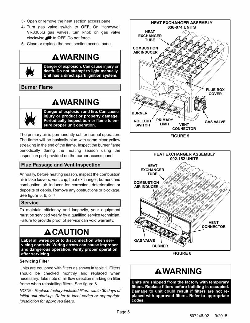
Page 6507246-02 9/2015
3- Open or remove the heat section access panel.
4- Turn gas valve switch to OFF. On Honeywell
VR8305Q gas valves, turn knob on gas valve
clockwise to OFF. Do not force.
5- Close or replace the heat section access panel.
WARNINGDanger of explosion. Can cause injury ordeath. Do not attempt to light manually.Unit has a direct spark ignition system.
Burner Flame
WARNINGDanger of explosion and fire. Can causeinjury or product or property damage.Periodically inspect burner flame to ensure proper unit operation.
The primary air is permanently set for normal operation.
The flame will be basically blue with some clear yellow
streaking in the end of the flame. Inspect the burner flame
periodically during the heating season using the
inspection port provided on the burner access panel.
Flue Passage and Vent Inspection
Annually, before heating season, inspect the combustion
air intake louvers, vent cap, heat exchanger, burners and
combustion air inducer for corrosion, deterioration or
deposits of debris. Remove any obstructions or blockage.
See figure 5, 6, or 7.
Service
To maintain efficiency and longevity, your equipment
must be serviced yearly by a qualified service technician.
Failure to provide proof of service can void warranty.
CAUTIONLabel all wires prior to disconnection when servicing controls. Wiring errors can cause improperand dangerous operation. Verify proper operationafter servicing.
Servicing Filter
Units are equipped with filters as shown in table 1. Filters
should be checked monthly and replaced when
necessary. Take note of air flow direction marking on filter
frame when reinstalling filters. See figure 8.
NOTE - Replace factory-installed filters within 30 days of
initial unit start-up. Refer to local codes or appropriate
jurisdiction for approved filters.
HEAT EXCHANGER ASSEMBLY036-074 UNITS
FIGURE 5
BURNER
COMBUSTIONAIR INDUCER
VENTCONNECTOR
GAS VALVE
HEATEXCHANGER
TUBE
PRIMARYLIMIT
ROLLOUTSWITCH
FLUE BOXCOVER
HEAT EXCHANGER ASSEMBLY092-152 UNITS
FIGURE 6
BURNER
COMBUSTIONAIR INDUCER
VENTCONNECTOR
GAS VALVE
HEATEXCHANGER
TUBE
WARNINGUnits are shipped from the factory with temporaryfilters. Replace filters before building is occupied.Damage to unit could result if filters are not replaced with approved filters. Refer to appropriatecodes.
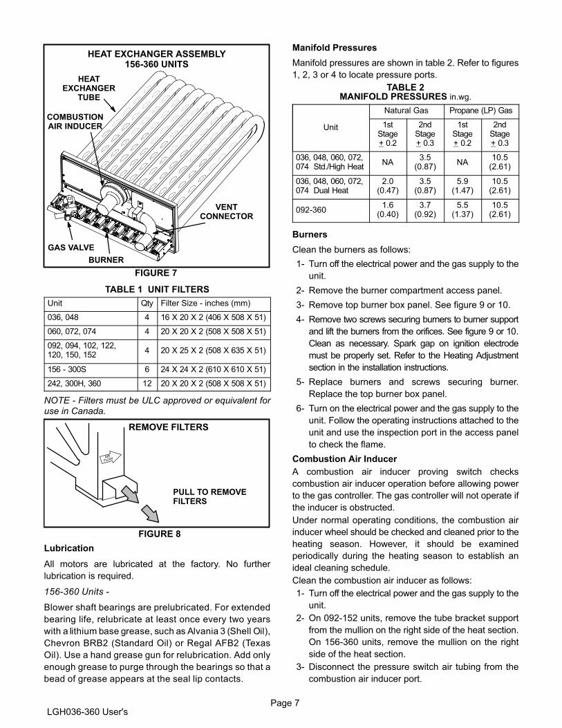
Page 7LGH036-360 User's
HEAT EXCHANGER ASSEMBLY156-360 UNITS
FIGURE 7
BURNER
COMBUSTIONAIR INDUCER
VENTCONNECTOR
GAS VALVE
HEATEXCHANGER
TUBE
TABLE 1 UNIT FILTERS
Unit Qty Filter Size - inches (mm)
036, 048 4 16 X 20 X 2 (406 X 508 X 51)
060, 072, 074 4 20 X 20 X 2 (508 X 508 X 51)
092, 094, 102, 122,120, 150, 152
4 20 X 25 X 2 (508 X 635 X 51)
156 - 300S 6 24 X 24 X 2 (610 X 610 X 51)
242, 300H, 360 12 20 X 20 X 2 (508 X 508 X 51)
NOTE - Filters must be ULC approved or equivalent foruse in Canada.
REMOVE FILTERS
FIGURE 8
PULL TO REMOVEFILTERS
Lubrication
All motors are lubricated at the factory. No further
lubrication is required.
156-360 Units -
Blower shaft bearings are prelubricated. For extended
bearing life, relubricate at least once every two years
with a lithium base grease, such as Alvania 3 (Shell Oil),
Chevron BRB2 (Standard Oil) or Regal AFB2 (Texas
Oil). Use a hand grease gun for relubrication. Add only
enough grease to purge through the bearings so that a
bead of grease appears at the seal lip contacts.
Manifold Pressures
Manifold pressures are shown in table 2. Refer to figures
1, 2, 3 or 4 to locate pressure ports.
TABLE 2MANIFOLD PRESSURES in.wg.
Unit
Natural Gas Propane (LP) Gas
1stStage+ 0.2
2ndStage+ 0.3
1stStage+ 0.2
2ndStage+ 0.3
036, 048, 060, 072,074 Std./High Heat
NA3.5
(0.87)NA
10.5(2.61)
036, 048, 060, 072,074 Dual Heat
2.0(0.47)
3.5(0.87)
5.9(1.47)
10.5(2.61)
092-3601.6
(0.40)3.7
(0.92)5.5
(1.37)10.5
(2.61)
Burners
Clean the burners as follows:
1- Turn off the electrical power and the gas supply to the
unit.
2- Remove the burner compartment access panel.
3- Remove top burner box panel. See figure 9 or 10.
4- Remove two screws securing burners to burner support
and lift the burners from the orifices. See figure 9 or 10.
Clean as necessary. Spark gap on ignition electrode
must be properly set. Refer to the Heating Adjustment
section in the installation instructions.
5- Replace burners and screws securing burner.
Replace the top burner box panel.
6- Turn on the electrical power and the gas supply to the
unit. Follow the operating instructions attached to the
unit and use the inspection port in the access panel
to check the flame.
Combustion Air Inducer
A combustion air inducer proving switch checks
combustion air inducer operation before allowing power
to the gas controller. The gas controller will not operate if
the inducer is obstructed.
Under normal operating conditions, the combustion air
inducer wheel should be checked and cleaned prior to the
heating season. However, it should be examined
periodically during the heating season to establish an
ideal cleaning schedule.
Clean the combustion air inducer as follows:
1- Turn off the electrical power and the gas supply to the
unit.
2- On 092-152 units, remove the tube bracket support
from the mullion on the right side of the heat section.
On 156-360 units, remove the mullion on the right
side of the heat section.
3- Disconnect the pressure switch air tubing from the
combustion air inducer port.
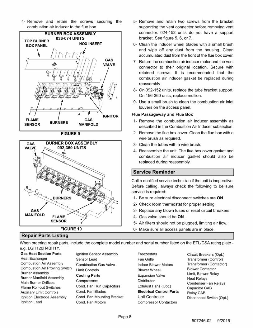
Page 8507246-02 9/2015
4- Remove and retain the screws securing the
combustion air inducer to the flue box.
FIGURE 9
BURNER BOX ASSEMBLY036-074 UNITS
GAS
VALVE
GAS
MANIFOLD
FLAME
SENSORBURNERS
IGNITOR
TOP BURNER
BOX PANELNOX INSERT
BURNER BOX ASSEMBLY092-360 UNITS
FIGURE 10
GASMANIFOLD
FLAMESENSOR
GASVALVE
BURNERS
5- Remove and retain two screws from the bracket
supporting the vent connector before removing vent
connector. 024-152 units do not have a support
bracket. See figure 5, 6, or 7.
6- Clean the inducer wheel blades with a small brush
and wipe off any dust from the housing. Clean
accumulated dust from the front of the flue box cover.
7- Return the combustion air inducer motor and the vent
connector to their original location. Secure with
retained screws. It is recommended that the
combustion air inducer gasket be replaced during
reassembly.
8- On 092-152 units, replace the tube bracket support.
On 156-360 units, replace mullion.
9- Use a small brush to clean the combustion air inlet
louvers on the access panel.
Flue Passageway and Flue Box
1- Remove the combustion air inducer assembly as
described in the Combustion Air Inducer subsection.
2- Remove the flue box cover. Clean the flue box with a
wire brush as required.
3- Clean the tubes with a wire brush.
4- Reassemble the unit. The flue box cover gasket and
combustion air inducer gasket should also be
replaced during reassembly.
Service Reminder
Call a qualified service technician if the unit is inoperative.
Before calling, always check the following to be sure
service is required:
1- Be sure electrical disconnect switches are ON.
2- Check room thermostat for proper setting.
3- Replace any blown fuses or reset circuit breakers.
4- Gas valve should be ON.
5- Air filters should not be plugged, limiting air flow.
6- Make sure all access panels are in place.
Repair Parts Listing
When ordering repair parts, include the complete model number and serial number listed on the ETL/CSA rating plate -
e.g. LGH120H4BH1Y.
Gas Heat Section Parts
Heat Exchanger
Combustion Air Assembly
Combustion Air Proving Switch
Burner Assembly
Burner Manifold Assembly
Main Burner Orifices
Flame Roll-out Switches
Auxiliary Limit Controls
Ignition Electrode Assembly
Ignition Lead
Ignition Sensor Assembly
Sensor Lead
Combination Gas Valve
Limit Controls
Cooling Parts
Compressors
Cond. Fan Run Capacitors
Cond. Fan Blades
Cond. Fan Mounting Bracket
Cond. Fan Motors
Freezestats
Fan Grille
Indoor Blower Motors
Blower Wheel
Expansion Valve
Distributor
Exhaust Fans (Opt.)
Electrical Control Parts
Unit Controller
Compressor Contactors
Circuit Breakers (Opt.)
Transformer (Control)
Transformer (Contactor)
Blower Contactor
Limit, Blower Relay
Heat Relays
Condenser Fan Relays
Capacitor CAB
Relay CAB
Disconnect Switch (Opt.)
Page 1
2015
See unit nameplate for manufacturerand address.
Litho U.S.A.
INSTALLATIONINSTRUCTIONSAGENCY REQUIRED
RETAIN THESE INSTRUCTIONSFOR FUTURE REFERENCE
3 THROUGH 30 TONSLGH036-360 UNITS
PACKAGED GAS AND COOLING UNITS506373-029/2015Supersedes 506373-01
Table of Contents
Safety 1. . . . . . . . . . . . . . . . . . . . . . . . . . . . . . . . . . . . . . . . . . . .
Connect Gas Piping 3. . . . . . . . . . . . . . . . . . . . . . . . . . . . . . .
High Altitude Derate 4. . . . . . . . . . . . . . . . . . . . . . . . . . . . . . .
Pressure Test Gas Piping 4. . . . . . . . . . . . . . . . . . . . . . . . . . .
Two Stage Gas Valve Adjustment 5. . . . . . . . . . . . . . . . . . . .
Gas Heat Operation 5. . . . . . . . . . . . . . . . . . . . . . . . . . . . . . .
Proper Gas Flow 5. . . . . . . . . . . . . . . . . . . . . . . . . . . . . . . . . .
Typical Gas Heat Schematic 6. . . . . . . . . . . . . . . . . . . . . . . .
Typical Unit Schematic 7. . . . . . . . . . . . . . . . . . . . . . . . . . . . .
Repair Parts Listing 8. . . . . . . . . . . . . . . . . . . . . . . . . . . . . . . .
Safety
WARNINGImproper installation, adjustment, alteration, service or maintenance can cause property damage,personal injury or loss of life. Installation and service must be performed by a licensed professionalHVAC installer or equivalent, service agency, or thegas supplier
Use of this unit as a construction heater or air conditioner
is not recommended during any phase of construction.
Very low return air temperatures, harmful vapors and
operation of the unit with clogged or misplaced filters will
damage the unit.
If this unit has been used for heating or cooling of
buildings or structures under construction, the following
conditions must be met or the warranty will be void:
� The vent hood must be installed per these installation
instructions.
� A room thermostat must control the unit. The use of
fixed jumpers that will provide continuous heating or
cooling is not allowed.
� A pre-filter must be installed at the entry to the return
air duct.
� The return air duct must be provided and sealed to
the unit.
� Return air temperature range between 55°F (13°C)
and 80°F (27°C) must be maintained.
� Air filters must be replaced and pre-filter must be
removed upon construction completion.
� The input rate and temperature rise must be set per
the unit rating plate.
� The heat exchanger, components, duct system, air
filters and evaporator coil must be thoroughly
cleaned following final construction clean-up.
� The unit operating conditions (including airflow,
cooling operation, ignition, input rate, temperature
rise and venting) must be verified according to these
installation instructions.
NOTE - The Commonwealth of Massachusetts
stipulates these additional requirements:
� Gas units shall be installed by a licensed plumber
or gas fitter only.
� The gas cock must be “T handle” type.
The unit is certified for installation on noncombustible
floors only. However, it may be installed on wood flooring,
or on class A, class B, or class C material covered floors
when used in horizontal discharge applications or in
downflow discharge applications when mounted on a
C1CURB or E1CURB roof mounting frame.
Adequate clearance shall be provided around air
openings into the vestibule area. Provisions shall be
made for proper operation and for combustion air and
ventilation air supply. Unit must be adjusted for the
temperature rise range and within the allowable external
static pressure on furnaces with a duct system as listed
on unit nameplate.
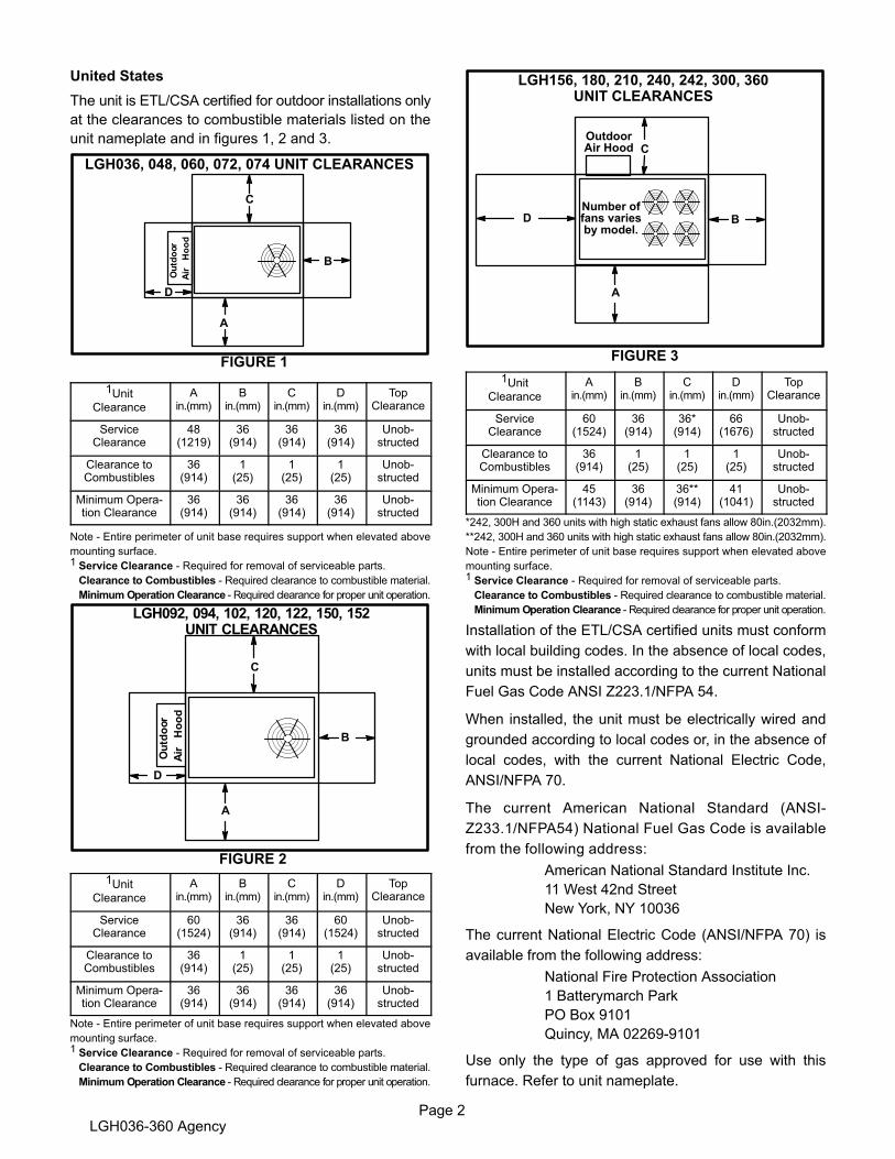
Page 2LGH036-360 Agency
United States
The unit is ETL/CSA certified for outdoor installations only
at the clearances to combustible materials listed on the
unit nameplate and in figures 1, 2 and 3.
LGH036, 048, 060, 072, 074 UNIT CLEARANCES
C
D
B
A
FIGURE 1
1UnitClearance
Ain.(mm)
Bin.(mm)
Cin.(mm)
Din.(mm)
TopClearance
ServiceClearance
48(1219)
36(914)
36(914)
36(914)
Unobstructed
Clearance toCombustibles
36(914)
1(25)
1(25)
1(25)
Unobstructed
Minimum Operation Clearance
36(914)
36(914)
36(914)
36(914)
Unobstructed
Note - Entire perimeter of unit base requires support when elevated above
mounting surface.
1 Service Clearance - Required for removal of serviceable parts.
Clearance to Combustibles - Required clearance to combustible material.
Minimum Operation Clearance - Required clearance for proper unit operation.
LGH092, 094, 102, 120, 122, 150, 152UNIT CLEARANCES
FIGURE 2
C
D
B
A
1UnitClearance
Ain.(mm)
Bin.(mm)
Cin.(mm)
Din.(mm)
TopClearance
ServiceClearance
60(1524)
36(914)
36(914)
60(1524)
Unobstructed
Clearance toCombustibles
36(914)
1(25)
1(25)
1(25)
Unobstructed
Minimum Operation Clearance
36(914)
36(914)
36(914)
36(914)
Unobstructed
Note - Entire perimeter of unit base requires support when elevated above
mounting surface.
1 Service Clearance - Required for removal of serviceable parts.
Clearance to Combustibles - Required clearance to combustible material.
Minimum Operation Clearance - Required clearance for proper unit operation.
LGH156, 180, 210, 240, 242, 300, 360UNIT CLEARANCES
C
D B
A
OutdoorAir Hood
FIGURE 3
Number offans variesby model.
1UnitClearance
Ain.(mm)
Bin.(mm)
Cin.(mm)
Din.(mm)
TopClearance
ServiceClearance
60(1524)
36(914)
36*(914)
66(1676)
Unobstructed
Clearance toCombustibles
36(914)
1(25)
1(25)
1(25)
Unobstructed
Minimum Operation Clearance
45(1143)
36(914)
36**(914)
41(1041)
Unobstructed
*242, 300H and 360 units with high static exhaust fans allow 80in.(2032mm).
**242, 300H and 360 units with high static exhaust fans allow 80in.(2032mm).
Note - Entire perimeter of unit base requires support when elevated above
mounting surface.
1 Service Clearance - Required for removal of serviceable parts.
Clearance to Combustibles - Required clearance to combustible material.
Minimum Operation Clearance - Required clearance for proper unit operation.
Installation of the ETL/CSA certified units must conform
with local building codes. In the absence of local codes,
units must be installed according to the current National
Fuel Gas Code ANSI Z223.1/NFPA 54.
When installed, the unit must be electrically wired and
grounded according to local codes or, in the absence of
local codes, with the current National Electric Code,
ANSI/NFPA 70.
The current American National Standard (ANSI-
Z233.1/NFPA54) National Fuel Gas Code is available
from the following address:
American National Standard Institute Inc.
11 West 42nd Street
New York, NY 10036
The current National Electric Code (ANSI/NFPA 70) is
available from the following address:
National Fire Protection Association
1 Batterymarch Park
PO Box 9101
Quincy, MA 02269-9101
Use only the type of gas approved for use with this
furnace. Refer to unit nameplate.
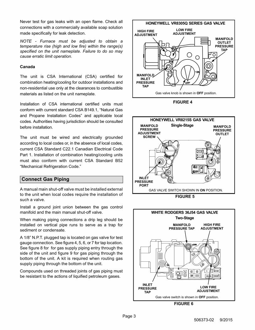
Page 3506373-02 9/2015
Never test for gas leaks with an open flame. Check all
connections with a commercially available soap solution
made specifically for leak detection.
NOTE - Furnace must be adjusted to obtain a
temperature rise (high and low fire) within the range(s)
specified on the unit nameplate. Failure to do so may
cause erratic limit operation.
Canada
The unit is CSA International (CSA) certified for
combination heating/cooling for outdoor installations and
non-residential use only at the clearances to combustible
materials as listed on the unit nameplate.
Installation of CSA international certified units must
conform with current standard CSA B149.1, “Natural Gas
and Propane Installation Codes” and applicable local
codes. Authorities having jurisdiction should be consulted
before installation.
The unit must be wired and electrically grounded
according to local codes or, in the absence of local codes,
current CSA Standard C22.1 Canadian Electrical Code
Part 1. Installation of combination heating/cooling units
must also conform with current CSA Standard B52
“Mechanical Refrigeration Code.”
Connect Gas Piping
A manual main shut-off valve must be installed external
to the unit when local codes require the installation of
such a valve.
Install a ground joint union between the gas control
manifold and the main manual shut-off valve.
When making piping connections a drip leg should be
installed on vertical pipe runs to serve as a trap for
sediment or condensate.
A 1/8” N.P.T. plugged tap is located on gas valve for test
gauge connection. See figure 4, 5, 6, or 7 for tap location.
See figure 8 for for gas supply piping entry through the
side of the unit and figure 9 for gas piping through the
bottom of the unit. A kit is required when routing gas
supply piping through the bottom of the unit.
Compounds used on threaded joints of gas piping must
be resistant to the actions of liquified petroleum gases.
HONEYWELL VR8305Q SERIES GAS VALVE
Gas valve knob is shown in OFF position.
FIGURE 4
LOW FIREADJUSTMENT
HIGH FIREADJUSTMENT
MANIFOLDINLET
PRESSURETAP
MANIFOLDOUTLET
PRESSURETAP
MANIFOLDPRESSURE
OUTLET
GAS VALVE SWITCH SHOWN IN ON POSITION.
INLETPRESSURE
PORT
MANIFOLDPRESSURE
ADJUSTMENTSCREW
FIGURE 5
HONEYWELL VR8215S GAS VALVE
Single-Stage
WHITE RODGERS 36J54 GAS VALVE
Two-Stage
Gas valve switch is shown in OFF position.
FIGURE 6
LOW FIREADJUSTMENT
HIGH FIREADJUSTMENT
INLETPRESSURE
TAP
MANIFOLDPRESSURE TAP
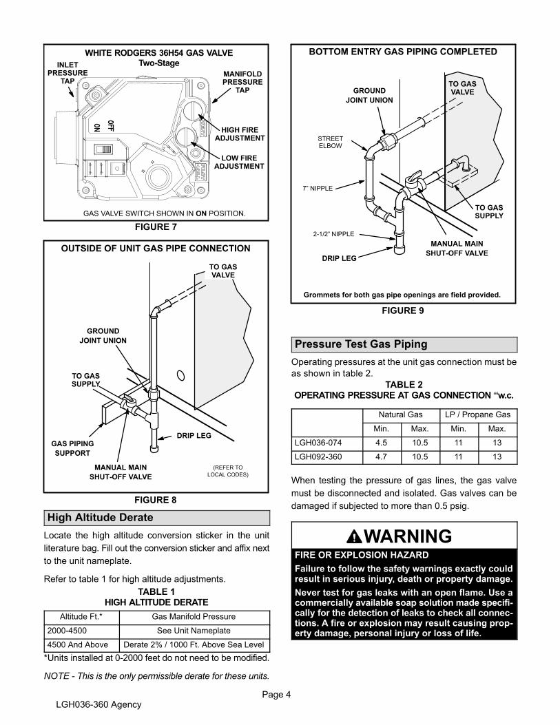
Page 4LGH036-360 Agency
WHITE RODGERS 36H54 GAS VALVETwo-Stage
FIGURE 7
LOW FIREADJUSTMENT
HIGH FIREADJUSTMENT
INLETPRESSURE
TAPMANIFOLDPRESSURE
TAP
GAS VALVE SWITCH SHOWN IN ON POSITION.
FIGURE 8
TO GASSUPPLY
MANUAL MAIN
SHUT-OFF VALVE
GAS PIPING
SUPPORT
GROUND
JOINT UNION
(REFER TO
LOCAL CODES)
DRIP LEG
OUTSIDE OF UNIT GAS PIPE CONNECTION
TO GASVALVE
High Altitude Derate
Locate the high altitude conversion sticker in the unit
literature bag. Fill out the conversion sticker and affix next
to the unit nameplate.
Refer to table 1 for high altitude adjustments.
TABLE 1HIGH ALTITUDE DERATE
Altitude Ft.* Gas Manifold Pressure
2000-4500 See Unit Nameplate
4500 And Above Derate 2% / 1000 Ft. Above Sea Level
*Units installed at 0-2000 feet do not need to be modified.
NOTE ‐ This is the only permissible derate for these units.
DRIP LEG
MANUAL MAIN
SHUT-OFF VALVE
GROUND
JOINT UNION
FIGURE 9
BOTTOM ENTRY GAS PIPING COMPLETED
7” NIPPLE
STREETELBOW
TO GASSUPPLY
TO GASVALVE
Grommets for both gas pipe openings are field provided.
2-1/2” NIPPLE
Pressure Test Gas Piping
Operating pressures at the unit gas connection must be
as shown in table 2.
TABLE 2OPERATING PRESSURE AT GAS CONNECTION “w.c.
Natural Gas LP / Propane Gas
Min. Max. Min. Max.
LGH036-074 4.5 10.5 11 13
LGH092-360 4.7 10.5 11 13
When testing the pressure of gas lines, the gas valve
must be disconnected and isolated. Gas valves can be
damaged if subjected to more than 0.5 psig.
WARNINGFIRE OR EXPLOSION HAZARD
Failure to follow the safety warnings exactly couldresult in serious injury, death or property damage.
Never test for gas leaks with an open flame. Use acommercially available soap solution made specifically for the detection of leaks to check all connections. A fire or explosion may result causing property damage, personal injury or loss of life.

Page 5506373-02 9/2015
Two-Stage Gas Valve Adjustment
Gas manifold pressures should match pressures shown
in table 3. On two stage gas valves, initiate a W2
thermostat demand to check high fire pressure before low
fire pressure. With high fire operating, reduce the
thermostat demand to W1 and check the low fire
pressure. Refer to the Unit Controller manual to initiate a
thermostat demand.
IMPORTANT - Do not set low fire pressure lower than
the certified minimum input rating listed in table 3.
TABLE 3MANIFOLD INPUT PRESSURES in.wg.
Unit
Natural GasPropane (LP)
Gas
1stStage+ 0.2
2ndStage+ 0.3
1stStage+ 0.2
2ndStage+ 0.3
036, 048, 060, 072, 074Std./Med./High Heat
NA 3.5 NA 10.5
036, 048, 060, 072,074 Dual Heat
2.0 3.5 5.9 10.5
092- 360 1.6 3.7 5.5 10.5
Gas Heat Operation
See the operating instruction plate on the unit for details.
Proper Gas Flow (Approximate)
1- Operate unit at least 15 minutes before checking gas
flow. Determine the time in seconds for two
revolutions of gas through the meter. (Two
revolutions assures a more accurate time.) A
portable LP gas meter (17Y44) is available for LP
applications.
2- Divide the number of seconds by two and
compare to the time in table 4. If manifold pressure is
correct and rate is incorrect, check gas orifices for
proper size and restriction.
3- Remove temporary gas meter if installed.
NOTE- To obtain accurate reading, shut off all other
gas appliances connected to meter.
TABLE 4
GAS METER CLOCKING CHART
UnitInputRate
(Btuh)
Seconds for One Revolution
Natural LP
1 cu ftDial
2 cu ftDial
1 cu ftDial
2 cu ftDial
65,000 55 111 138 277
78,000 46 92 115 231
108,000 33 67 83 167
125,000 29 58 72 144
130,000 28 55 69 138
150,000 24 48 60 120
169,000 21 43 53 107
180,000 20 40 50 100
240,000 15 30 38 75
260,000 14 28 35 69
360,000 10 20 30 50
480,000 8 15 19 38
Natural-1000 btu/cu ft LP-2500 btu/cu ft
Note: Table assumes standard temperature (60°F), pressure
(30in.Hg.), and fuel heating values (Btuh/Ft.3). Apply pressure
corrections in altitudes above 2000 ft.

Page 6LGH036-360 Agency
TYPICAL GAS HEAT SCHEMATICThis schematic is typical. See the wiring schematic on the unit for actual unit wiring.

Page 7506373-02 9/2015
TYPICAL UNIT SCHEMATICThis schematic is typical. See the wiringschematic on the unit for actual unit wiring.

Page 8LGH036-360 Agency
Repair Parts Listing
When ordering repair parts, include the complete model number and serial number listed on the ETL/CSA rating plate -
e.g. LGH120H4BH1Y.
Gas Heat Section Parts
Heat Exchanger
Combustion Air Assembly
Combustion Air Proving Switch
Burner Assembly
Burner Manifold Assembly
Main Burner Orifices
Flame Roll-out Switches
Auxiliary Limit Controls
Ignition Electrode Assembly
Ignition Lead
Ignition Sensor Assembly
Sensor Lead
Combination Gas Valve
Limit Controls
Cooling Parts
Compressors
Condenser Fan Motors
Condenser Fan Blades
Condenser Fan Run Capacitors
Freezestats
Condenser Fan Mounting Bracket
Fan Grille
Indoor Blower Motors
Blower Wheel
Expansion Valve
Distributor
Exhaust Fans (Opt.)
Electrical Control Parts
Unit Controller
Compressor Contactors
Circuit Breakers (Opt.)
Transformer (Control)
Transformer (Contactor)
Blower Contactor
Limit, Blower Relay
Heat Relays
Condenser Fan Relays
Capacitor CAB
Relay CAB
Disconnect Switch (Opt.)

Litho U.S.A.©2015
507241-02 4/2015Supersedes 3/2015
PRODIGY® 2.0INSTALLATION AND SETUP GUIDE
Prodigy® 2.0 (M3 Unit Controller) Installation and Setup Guide
Table Of Contents
Description 1. . . . . . . . . . . . . . . . . . . . . . . . . . . . . . . . . . .
M3 Unit Controller - Connections, Input/Outputs, jumpers and LEDs Locations 2. . . . . . . . . . . . . . . . . . . .
System Status Screen 4. . . . . . . . . . . . . . . . . . . . . . . . .
Firmware Update 6. . . . . . . . . . . . . . . . . . . . . . . . . . . . . .
Configuration Identifier Settings 7. . . . . . . . . . . . . . . . .
Level 1 Menu Level Selections 10. . . . . . . . . . . . . . . . . .
Menu Interface Details 11. . . . . . . . . . . . . . . . . . . . . . . . .
Blower Operation with Effective Occupancy 22. . . . . . .
Economizer 24. . . . . . . . . . . . . . . . . . . . . . . . . . . . . . . . . . .
Networking Serial Communications (RS-485) 33. . . . . .
APPENDIX:
Abbreviations 34. . . . . . . . . . . . . . . . . . . . . . . . . . . . .
Parts List 34. . . . . . . . . . . . . . . . . . . . . . . . . . . . . . . . .
USB Service Report Example 35. . . . . . . . . . . . . . .
Alarm Codes 37. . . . . . . . . . . . . . . . . . . . . . . . . . . . . .
Controller Signal References 55. . . . . . . . . . . . . . . .
Wiring Diagrams 50. . . . . . . . . . . . . . . . . . . . . . . . . . .
Quick Start Guide 52. . . . . . . . . . . . . . . . . . . . . . . . . .
Description
The M3 unit controller:
� provides control functions for Energence® RooftopUnits,
� includes a 4 x 20 LCD display, USB port, menu selectionLED, and various navigation tools,
� provides status and diagnostic information fortroubleshooting,
� allows adjustment of time delays and setpoints thatenable advanced features,
� is controlled by a standard room thermostat, direct digitalcontroller (DDC), or a room sensor,
� can be configured as a device on the network whendaisy-chained to the L Connection® Network,
� may be connected to a PC which has been loaded withunit controller software,
� accepts add-on boards to build variations according toapplication or equipment type.
� USB verification and profile sharing.
� For all available M3 unit controller documentation, see
the Lennox Commercial website.
www.lennoxcommercial.com.
Start-Up Procedure
WARNINGImproper installation, adjustment, alteration, service ormaintenance can cause property damage, personal injuryor loss of life. Installation and service must be performedby a qualified installer, service agency or the gas supplier
1. Turn on unit and dismiss alarm messages as necessary.
2. Follow SETUP > INSTALL menu to properly configureunit
3. Be sure unit is in normal operating mode as seen ondisplay (COOLING, HEATING, IDLE, etc).
4. To verify operation use SERVICE > TEST menu.
See Quick Start Guide section at the end of this manual foradditional information.
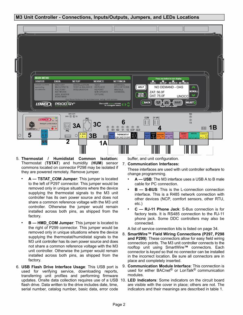
Page 2
M3 Unit Controller - Connections, Inputs/Outputs, Jumpers, and LEDs Locations
4
2
3A
1A
3C
5 3B
61B
NO DEMAND - OAS
ZAT: 56.0FDAT: 75.0F UNOCC
5. Thermostat / Humidistat Common Isolation:Thermostat (TSTAT) and humidity (HUM) sensorcommons located on connector P298 may be isolated ifthey are powered remotely. Remove jumper.
� A — TSTAT_COM Jumper: This jumper is located
to the left of P297 connector. This jumper would beremoved only in unique situations where the device
supplying the thermostat signals to the M3 unitcontroller has its own power source and does not
share a common reference voltage with the M3 unitcontroller. Otherwise the jumper would remaininstalled across both pins, as shipped from the
factory.
� B — HMD_COM Jumper: This jumper is located to
the right of P299 connector. This jumper would beremoved only in unique situations where the device
supplying the thermostat/humidistat signals to theM3 unit controller has its own power source and does
not share a common reference voltage with the M3unit controller. Otherwise the jumper would remaininstalled across both pins, as shipped from the
factory.
6. USB Flash Drive Interface Usage: This USB port isused for verifying service, downloading reports,transferring unit profiles and performing firmwareupdates. Onsite data collection requires use of a USBflash drive. Data written to the drive includes date, time,serial number, catalog number, basic data, error code
buffer, and unit configuration.
7. Communication Interfaces:
These interfaces are used with unit controller software tochange programming.
� A — USB: The M3 interface uses a USB A to B male
cable for PC connection.
� B — S-BUS: This is the L-connection connection
interface. This is a R485 network connection withother devices (NCP, comfort sensors, other RTU,
etc.)
� C — RJ-11 Phone Jack: S-Bus connection is for
factory tests. It is RS485 connection to the RJ-11
phone jack. Some DDC controllers may also beconnected.
A list of service connection kits is listed on page 34.
8. SmartWire™ Field Wiring Connections (P297, P298and P299): These connectors allow for easy field wiringconnection points. The M3 unit controller connects to therooftop unit using SmartWire™ connectors. Eachconnector is keyed so that no connector can be installedin the incorrect location. Be sure all connectors are inplace and completely inserted.
9. Communication Module Interface: This connection isused for either BACnet® or LonTalk® communicationmodules.
10. LED Indicators: Some indicators on the circuit boardare visible with the cover in place; others are not. Theindicators and their meanings are described in table 1.

Page 3
Page 3
Table 1. LED Operation Indications
LED Status Indication Meaning
Heartbeat (HB) (D33)
Green Slow Flash Normal Operation
Green Fast Flash Bootloader / firmware update mode
UNLIT Steady Off No voltage to M3 board or defective board
Green Steady OnUnit in configuration / test mode (not innormal mode)
S-BUS / PCConnection (D70and D71)
BUS (green) Flickering ON Network traffic present
TX (yellow) Flickering ON Unit controller is transmitting
BACnet (option) -LEDs located onmodule
RX (green) Flickering ON Unit controller is receiving
TX (yellow) Flickering ON Unit controller is transmitting
LonTalk (option) -LEDs located onmodule
RX (green) Flickering ON Unit controller is receiving
TX (yellow) Flickering ON Unit controller is transmitting
SERVICE (red)Flashing 1 sec. on; 1sec. off
Node is not configured; application loaded
SERVICE (UNLIT) Steady off Node is completely configured
SERVICE (red) Constant on Node is configured; no application loaded
SERVICE (red)Quick flashes duringinitialization
Messages being passed to M3; normaloperation
Thermostat Input YellowIndicates a thermostatdemand
G - Blower on (D17)W1 - First-Stage Heating (D20)W2 - Second -Stage Heating (D23)Y1 - First-Stage Cooling (D26)Y2 - Second-Stage Cooling (D29)OCP - Occupied (D32)GLO - Global input (D38)
Thermostat LEDs indicate only with incoming thermostat connection via SmartWire� connectors.
Slow Flash = 1 second on; 1 second off.
Fast Flash = ½ second on; ½ second off.
A “flickering” LED flashes significantly faster than a “fast flash“.
NOTE - LEDs are energized by 24VAC thermostat inputs.
CAUTION
ELECTROSTATIC DISCHARGE (ESD)Precautions and Procedures
Electrostatic discharge can affect electronic components. Take precautionsduring unit installation and service to protect the unit's electronic controls.Precautions will help to avoid control exposure to electrostatic discharge byputting the unit, the control and the technician at the same electrostaticpotential. Neutralize electrostatic charge by touching hand and all tools on anunpainted unit surface before performing any service procedure
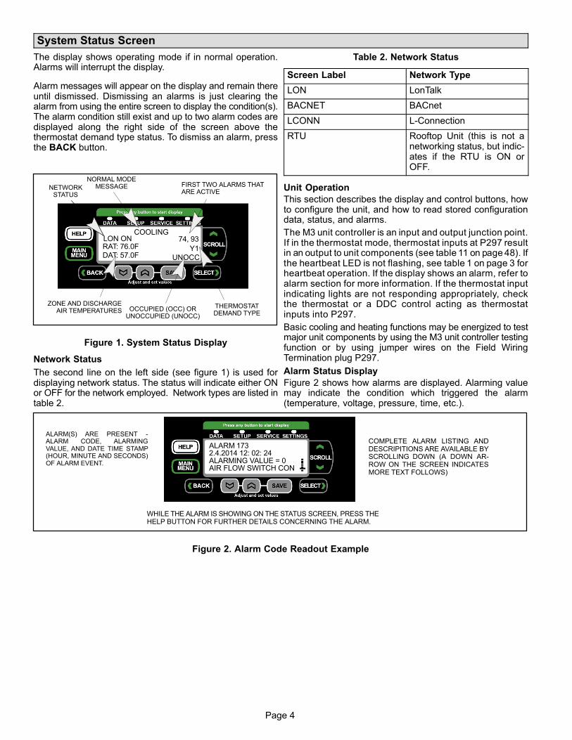
Page 4
System Status Screen
The display shows operating mode if in normal operation.Alarms will interrupt the display.
Alarm messages will appear on the display and remain thereuntil dismissed. Dismissing an alarms is just clearing thealarm from using the entire screen to display the condition(s).The alarm condition still exist and up to two alarm codes aredisplayed along the right side of the screen above thethermostat demand type status. To dismiss an alarm, pressthe BACK button.
COOLING
UNOCC
RAT: 76.0FDAT: 57.0F
ZONE AND DISCHARGEAIR TEMPERATURES OCCUPIED (OCC) OR
UNOCCUPIED (UNOCC)
FIRST TWO ALARMS THATARE ACTIVE
NORMAL MODEMESSAGE
Y1
THERMOSTATDEMAND TYPE
74, 93LON ON
NETWORKSTATUS
Figure 1. System Status Display
Network Status
The second line on the left side (see figure 1) is used fordisplaying network status. The status will indicate either ONor OFF for the network employed. Network types are listed intable 2.
Table 2. Network Status
Screen Label Network Type
LON LonTalk
BACNET BACnet
LCONN L-Connection
RTU Rooftop Unit (this is not anetworking status, but indicates if the RTU is ON orOFF.
Unit Operation
This section describes the display and control buttons, howto configure the unit, and how to read stored configurationdata, status, and alarms.
The M3 unit controller is an input and output junction point.If in the thermostat mode, thermostat inputs at P297 resultin an output to unit components (see table 11 on page 48). Ifthe heartbeat LED is not flashing, see table 1 on page 3 forheartbeat operation. If the display shows an alarm, refer toalarm section for more information. If the thermostat inputindicating lights are not responding appropriately, checkthe thermostat or a DDC control acting as thermostatinputs into P297.
Basic cooling and heating functions may be energized to testmajor unit components by using the M3 unit controller testingfunction or by using jumper wires on the Field WiringTermination plug P297.
Alarm Status Display
Figure 2 shows how alarms are displayed. Alarming valuemay indicate the condition which triggered the alarm(temperature, voltage, pressure, time, etc.).
ALARM 1732.4.2014 12: 02: 24ALARMING VALUE = 0AIR FLOW SWITCH CON
ALARM(S) ARE PRESENT -ALARM CODE, ALARMINGVALUE, AND DATE TIME STAMP(HOUR, MINUTE AND SECONDS)OF ALARM EVENT.
COMPLETE ALARM LISTING ANDDESCRIPITIONS ARE AVAILABLE BYSCROLLING DOWN (A DOWN ARROW ON THE SCREEN INDICATESMORE TEXT FOLLOWS)
WHILE THE ALARM IS SHOWING ON THE STATUS SCREEN, PRESS THEHELP BUTTON FOR FURTHER DETAILS CONCERNING THE ALARM.
Figure 2. Alarm Code Readout Example

Page 5
Page 5
Normal Mode Messages
The format of the message is mode and setpoint (see table 3).
Table 3. Possible MODE messages
COMP LOADSHEDDING
Unit is running at lower power capacity
COOLING Cool demand present; unit is in mechanical cooling.
DEHUMIDIFICATION Unit is dehumidifying
FREE COOLING Cooling demand is present, no compressor cooling.
FRESH AIR COOLING Cool ventilation air to neutral value
FRESH AIR HEATING Heat ventilation air to neutral value
HEATING Heat demand present; unit is heating
CONTROLLERLOCKOUT
User has disabled controller operation.
LOW AMBIENTLOCKOUT
Outdoor air is too cold to allow compressors to run.
MORNING WARMUP Outdoor air damper closed
OFF ON ALARM
Unit is off due presence of alarm(s) that the system has determined will halt system operations. This system status could be present with no active alarms, which usually indicates the alarm condition(s) are no longer present. If the system has cleared the alarmthere is usually a five minute delay before resuming system operations.
NOTE: Not all alarms will halt system operation. The first two active alarms are displayedon the main system status screen (see figure 2).
PRE-COOL
Compressor not allowed—free cooling. (During the first 30 minutes of the first coolingdemand following a change from unoccupied to occupied, calls for mechanical [compressor] cooling are ignored if an economizer is installed and if outdoor air is suitable for freecooling.)
PREINSTALL Unit has not been set up for operation. Must follow installation menus
START UPDefault start up delay before servicing demands. Go to M3 user interface: SETUP > INSTALL
SMOKE ALARM Smoke input detected
TEST Network has unit in test mode
BLOWER ON Indoor blower is on.
BLOWER ON - OAS Indoor blower is on and outdoor air is suitable.
NO DEMAND System not receiving a demand for cooling or heating.
NO DEMAND - OAS System not receiving a demand for cooling or heating and outdoor air is suitable.
COOL + MAX OPENECON
Mechanical cooling is operating with maximum free cooling.
COOL + MODULATEECON
Mechanical cooling is operating with variable free cooling.
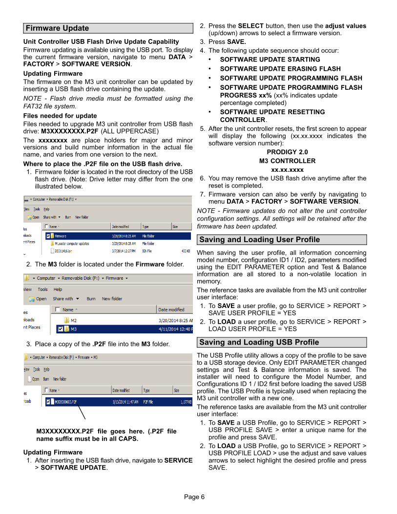
Page 6
Firmware Update
Unit Controller USB Flash Drive Update Capability
Firmware updating is available using the USB port. To displaythe current firmware version, navigate to menu DATA >FACTORY > SOFTWARE VERSION.
Updating Firmware
The firmware on the M3 unit controller can be updated byinserting a USB flash drive containing the update.
NOTE - Flash drive media must be formatted using the
FAT32 file system.
Files needed for update
Files needed to upgrade M3 unit controller from USB flashdrive: M3XXXXXXXX.P2F (ALL UPPERCASE)
The xxxxxxxx are place holders for major and minorversions and build number information in the actual filename, and varies from one version to the next.
Where to place the .P2F file on the USB flash drive.
1. Firmware folder is located in the root directory of the USBflash drive. (Note: Drive letter may differ from the oneillustrated below.
2. The M3 folder is located under the Firmware folder.
3. Place a copy of the .P2F file into the M3 folder.
M3XXXXXXXX.P2F file goes here. (.P2F filename suffix must be in all CAPS.
Updating Firmware
1. After inserting the USB flash drive, navigate to SERVICE> SOFTWARE UPDATE.
2. Press the SELECT button, then use the adjust values(up/down) arrows to select a firmware version.
3. Press SAVE.
4. The following update sequence should occur:
� SOFTWARE UPDATE STARTING
� SOFTWARE UPDATE ERASING FLASH
� SOFTWARE UPDATE PROGRAMMING FLASH
� SOFTWARE UPDATE PROGRAMMING FLASH
PROGRESS xx% (xx% indicates updatepercentage completed)
� SOFTWARE UPDATE RESETTING
CONTROLLER.
5. After the unit controller resets, the first screen to appearwill display the following (xx.xx.xxxx indicates thesoftware version number):
PRODIGY 2.0
M3 CONTROLLER
xx.xx.xxxx
6. You may remove the USB flash drive anytime after thereset is completed.
7. Firmware version can also be verify by navigating tomenu DATA > FACTORY > SOFTWARE VERSION.
NOTE - Firmware updates do not alter the unit controller
configuration settings. All settings will be retained after the
firmware has been updated.
Saving and Loading User Profile
When saving the user profile, all information concerningmodel number, configuration ID1 / ID2, parameters modifiedusing the EDIT PARAMETER option and Test & Balanceinformation are all stored to a non-volatile location inmemory.
The reference tasks are available from the M3 unit controlleruser interface:
1. To SAVE a user profile, go to SERVICE > REPORT >SAVE USER PROFILE = YES
2. To LOAD a user profile, go to SERVICE > REPORT >LOAD USER PROFILE = YES
Saving and Loading USB Profile
The USB Profile utility allows a copy of the profile to be saveto a USB storage device. Only EDIT PARAMETER changedsettings and Test & Balance information is saved. Theinstaller will need to configure the Model Number, andConfigurations ID 1 / ID2 first before loading the saved USBprofile. The USB Profile is typically used when replacing theM3 unit controller with a new one.
The reference tasks are available from the M3 unit controlleruser interface:
1. To SAVE a USB Profile, go to SERVICE > REPORT >USB PROFILE SAVE > enter a unique name for theprofile and press SAVE.
2. To LOAD a USB Profile, go to SERVICE > REPORT >USB PROFILE LOAD > use the adjust and save valuesarrows to select highlight the desired profile and pressSAVE.

Page 7
Page 7
Configuration Identifier Settings (Model Number and Configuration ID 1 / 2)
This section addresses the requirement that specific configuration information must be completed using the SETUP /INSTALL feature if a new unit controller was being installed. Other requirements are the addition of accessories that werenot factory-installed. Model number, configuration ID 1 and 2, catalog number, serial number and RTU description are all keyitems required to be completed for the system to operate correctly. Running the SETUP / INSTALL wizard allows theinstaller to verify that all fields have been completed as required.
Model Number
1 2 3 4 5 6 7 8 9 10 11 12
Type [1, 2, 3]
Electric = LCH
Gas = LGH
Tonnage [4, 5, 6]
Efficiency [7]
High Efficiency = H
Standard Efficiency = S
Ultra Efficiency = U
[10] Factory Electric or Gas
Heat
See unit nameplate for applicable electric
or gas heat designation.
[11] Design Sequence
1 = First revision
[12] Voltage
See unit nameplate for
applicable electric voltage
designation.
Refrigerant [8]
HFC-410A = 4
Blower Type [9]
Belt Drive (1 speed) = B
Direct Drive = D
Direct Drive ECM = E
MSAV Belt Drive = M
Belt Drive (2 speed) = T
IMPORTANT: Always refer to the model
information listed on the unit nameplate when
setting these options.
See unit nameplate for
applicable tonnage
designation.
Figure 3. Model Number
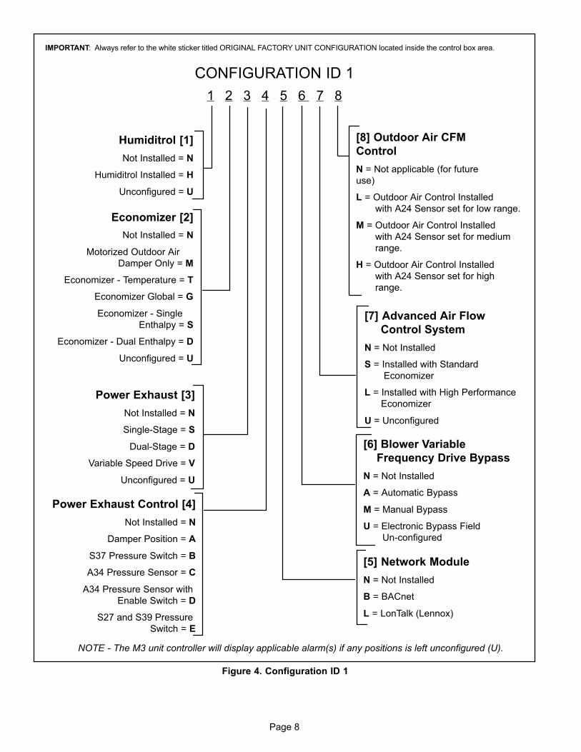
Page 8
CONFIGURATION ID 1
1 2 3 4 5 6 7 8
Humiditrol [1]
Not Installed = N
Humiditrol Installed = H
Unconfigured = U
Economizer [2]
Not Installed = N
Motorized Outdoor Air
Damper Only = M
Economizer - Temperature = T
Economizer Global = G
Economizer - Single
Enthalpy = S
Economizer - Dual Enthalpy = D
Unconfigured = U
Power Exhaust [3]
Not Installed = N
Single-Stage = S
Dual-Stage = D
Variable Speed Drive = V
Unconfigured = U
Power Exhaust Control [4]
Not Installed = N
Damper Position = A
S37 Pressure Switch = B
A34 Pressure Sensor = C
A34 Pressure Sensor with
Enable Switch = D
S27 and S39 Pressure
Switch = E
[5] Network Module
N = Not Installed
B = BACnet
L = LonTalk (Lennox)
[6] Blower Variable
Frequency Drive Bypass
N = Not Installed
A = Automatic Bypass
M = Manual Bypass
U = Electronic Bypass Field
Un-configured
[7] Advanced Air Flow
Control System
N = Not Installed
S = Installed with Standard
Economizer
L = Installed with High Performance
Economizer
U = Unconfigured
[8] Outdoor Air CFM
Control
N = Not applicable (for future
use)
L = Outdoor Air Control Installed
with A24 Sensor set for low range.
M = Outdoor Air Control Installed
with A24 Sensor set for medium
range.
H = Outdoor Air Control Installed
with A24 Sensor set for high
range.
IMPORTANT: Always refer to the white sticker titled ORIGINAL FACTORY UNIT CONFIGURATION located inside the control box area.
NOTE - The M3 unit controller will display applicable alarm(s) if any positions is left unconfigured (U).
Figure 4. Configuration ID 1
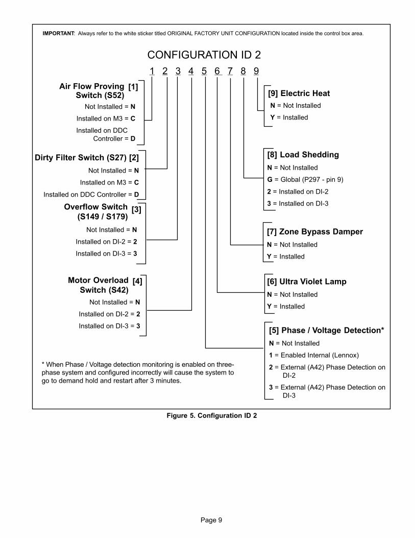
Page 9
Page 9
CONFIGURATION ID 2
1 2 3 4 5 6 7 8 9
Not Installed = N
Installed on M3 = C
Installed on DDC
Controller = D
Dirty Filter Switch (S27) [2]
Not Installed = N
Installed on M3 = C
Installed on DDC Controller = D
Not Installed = N
Installed on DI-2 = 2
Installed on DI-3 = 3
[5] Phase / Voltage Detection*
N = Not Installed
1 = Enabled Internal (Lennox)
2 = External (A42) Phase Detection on
DI-2
3 = External (A42) Phase Detection on
DI-3
N = Not Installed
Y = Installed
[8] Load Shedding
N = Not Installed
G = Global (P297 - pin 9)
2 = Installed on DI-2
3 = Installed on DI-3
[9] Electric Heat[1]Air Flow Proving
Switch (S52)
[3]Overflow Switch
(S149 / S179)
[4]Motor Overload
Switch (S42)
Not Installed = N
Installed on DI-2 = 2
Installed on DI-3 = 3
[7] Zone Bypass Damper
N = Not Installed
Y = Installed
[6] Ultra Violet Lamp
N = Not Installed
Y = Installed
* When Phase / Voltage detection monitoring is enabled on three-
phase system and configured incorrectly will cause the system to
go to demand hold and restart after 3 minutes.
IMPORTANT: Always refer to the white sticker titled ORIGINAL FACTORY UNIT CONFIGURATION located inside the control box area.
Figure 5. Configuration ID 2
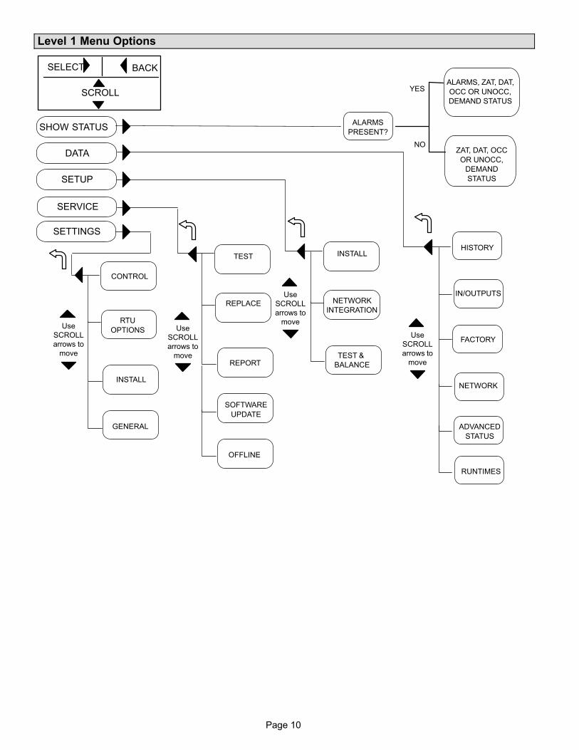
Page 10
Level 1 Menu Options
IN/OUTPUTS
FACTORY
NETWORK
INSTALL
NETWORK
INTEGRATION
TEST &
BALANCE
Use
SCROLL
arrows to
move
SETUP
DATA
SHOW STATUS
SERVICE
SETTINGS
ALARMS
PRESENT?
BACKSELECT
SCROLL
Use
SCROLL
arrows to
move
TEST
REPLACE
Use
SCROLL
arrows to
move
OFFLINE
REPORT
SOFTWARE
UPDATE
INSTALL
CONTROL
RTU
OPTIONS
GENERAL
Use
SCROLL
arrows to
move
ADVANCED
STATUS
RUNTIMES
HISTORY
ALARMS, ZAT, DAT,
OCC OR UNOCC,
DEMAND STATUS
ZAT, DAT, OCC
OR UNOCC,
DEMAND
STATUS
YES
NO
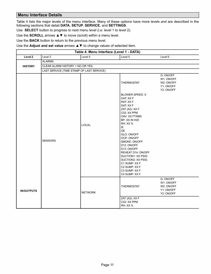
Page 11
Page 11
Menu Interface Details
Table 4 lists the major levels of the menu interface. Many of these options have more levels and are described in thefollowing sections that detail DATA, SETUP, SERVICE, and SETTINGS.
Use SELECT button to progress to next menu level (i.e. level 1 to level 2).
Use the SCROLL arrows ▲▼ to move (scroll) within a menu level.
Use the BACK button to return to the previous menu level.
Use the Adjust and set value arrows ▲▼ to change values of selected item.
Table 4. Menu Interface (Level 1 - DATA)
Level 2 Level 3 Level 4 Level 5 Level 6
HISTORY
ALARMS
CLEAR ALARM HISTORY = NO OR YES
LAST SERVICE (TIME STAMP OF LAST SERVICE)
IN/OUTPUTS
SENSORS
LOCAL
THERMOSTAT
G: ON/OFF
W1: ON/OFF
W2: ON/OFF
Y1: ON/OFF
Y2: ON/OFF
BLOWER SPEED: X
OAT: XX F
RAT: XX F
DAT: XX F
ZAT (A2): XX F
C02: XX PPM
OAV: XX FT/MIN
BP: XX IN H20
RH: XX %
IE
OE
GLO: ON/OFF
OCP: ON/OFF
SMOKE: ON/OFF
D12: ON/OFF
D13: ON/OFF
REHEAT D14: ON/OFF
SUCTION1: XX PSIG
SUCTION2: XX PSIG
C1 SUMP: XX F
C2 SUMP: XX F
C3 SUMP: XX F
C4 SUMP: XX F
NETWORK
THERMOSTAT
G: ON/OFF
W1: ON/OFF
W2: ON/OFF
Y1: ON/OFF
Y2: ON/OFF
ZAT (A2): XX F
C02: XX PPM
RH: XX %
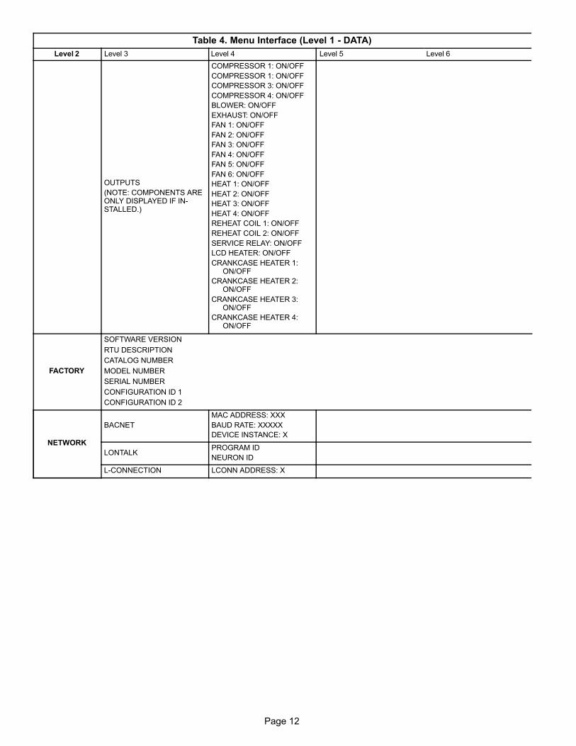
Page 12
Table 4. Menu Interface (Level 1 - DATA)
Level 2 Level 6Level 5Level 4Level 3
OUTPUTS
(NOTE: COMPONENTS AREONLY DISPLAYED IF INSTALLED.)
COMPRESSOR 1: ON/OFF
COMPRESSOR 1: ON/OFF
COMPRESSOR 3: ON/OFF
COMPRESSOR 4: ON/OFF
BLOWER: ON/OFF
EXHAUST: ON/OFF
FAN 1: ON/OFF
FAN 2: ON/OFF
FAN 3: ON/OFF
FAN 4: ON/OFF
FAN 5: ON/OFF
FAN 6: ON/OFF
HEAT 1: ON/OFF
HEAT 2: ON/OFF
HEAT 3: ON/OFF
HEAT 4: ON/OFF
REHEAT COIL 1: ON/OFF
REHEAT COIL 2: ON/OFF
SERVICE RELAY: ON/OFF
LCD HEATER: ON/OFF
CRANKCASE HEATER 1:ON/OFF
CRANKCASE HEATER 2:ON/OFF
CRANKCASE HEATER 3:ON/OFF
CRANKCASE HEATER 4:ON/OFF
FACTORY
SOFTWARE VERSION
RTU DESCRIPTION
CATALOG NUMBER
MODEL NUMBER
SERIAL NUMBER
CONFIGURATION ID 1
CONFIGURATION ID 2
NETWORK
BACNET
MAC ADDRESS: XXX
BAUD RATE: XXXXX
DEVICE INSTANCE: X
LONTALKPROGRAM ID
NEURON ID
L-CONNECTION LCONN ADDRESS: X
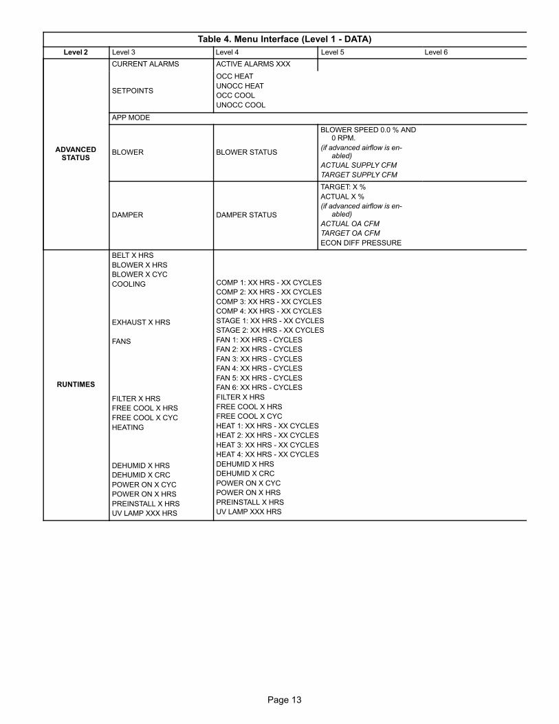
Page 13
Page 13
Table 4. Menu Interface (Level 1 - DATA)
Level 2 Level 6Level 5Level 4Level 3
ADVANCEDSTATUS
CURRENT ALARMS ACTIVE ALARMS XXX
SETPOINTS
OCC HEAT
UNOCC HEAT
OCC COOL
UNOCC COOL
APP MODE
BLOWER BLOWER STATUS
BLOWER SPEED 0.0 % AND0 RPM.
(if advanced airflow is enabled)
ACTUAL SUPPLY CFM
TARGET SUPPLY CFM
DAMPER DAMPER STATUS
TARGET: X %
ACTUAL X %
(if advanced airflow is enabled)
ACTUAL OA CFM
TARGET OA CFM
ECON DIFF PRESSURE
RUNTIMES
BELT X HRS
BLOWER X HRS
BLOWER X CYC
COOLING
EXHAUST X HRS
FANS
FILTER X HRS
FREE COOL X HRS
FREE COOL X CYC
HEATING
DEHUMID X HRS
DEHUMID X CRC
POWER ON X CYC
POWER ON X HRS
PREINSTALL X HRS
UV LAMP XXX HRS
COMP 1: XX HRS - XX CYCLES
COMP 2: XX HRS - XX CYCLES
COMP 3: XX HRS - XX CYCLES
COMP 4: XX HRS - XX CYCLES
STAGE 1: XX HRS - XX CYCLES
STAGE 2: XX HRS - XX CYCLES
FAN 1: XX HRS - CYCLES
FAN 2: XX HRS - CYCLES
FAN 3: XX HRS - CYCLES
FAN 4: XX HRS - CYCLES
FAN 5: XX HRS - CYCLES
FAN 6: XX HRS - CYCLES
FILTER X HRS
FREE COOL X HRS
FREE COOL X CYC
HEAT 1: XX HRS - XX CYCLES
HEAT 2: XX HRS - XX CYCLES
HEAT 3: XX HRS - XX CYCLES
HEAT 4: XX HRS - XX CYCLES
DEHUMID X HRS
DEHUMID X CRC
POWER ON X CYC
POWER ON X HRS
PREINSTALL X HRS
UV LAMP XXX HRS

Page 14
Table 5. Menu Interface (Level 1 - SETUP)
Level 2 Level 3 Level 4 Level 5 Level 6
INSTALL
LANGUAGE = = ENGLISH, ESPANOL, OR FRANCAIS
DATE/TIME = = DAY, MONTH, YEAR, HOURS, MINUTES, SECONDS
DISPLAY UNITS F/C = FAHRENHEIT OR CELSIUS
MODEL NUMBER = LOCATED ON UNIT NAMEPLATE.
CONFIGURATION ID 1SEE WHITE STICKER TITLED “ORIGINAL FACTORY UNIT CONFIGURATION” LOCATED ONTHE RIGHT SIDE OF THE CONTROL BOX NEAR THE M3 CONTROLLER.
CONFIGURATION ID 2WHITE STICKER TITLED “ORIGINAL FACTORY UNIT CONFIGURATION” LOCATED ON THERIGHT SIDE OF THE CONTROL BOX NEAR THE M3 CONTROLLER.
CATALOG NUMBER LOCATED ON UNIT NAMEPLATE
SERIAL NUMBER LOCATED ON UNIT NAMEPLATE
RTU DESCRIPTION = UP TO 18 ALPHA/NUMERIC CHARACTERS
DEHUMIDIFIERSENSOR TYPE
= NONE OR REHEAT DI4
= LOCAL SENSOR ORNETWORK SENSOR
DEHUMIDIFIER DEHUMID SETPOINT = X.XX %
DEHUMIDIFIER DEHUMID DEADBAND = X.X %
NOTE: PARAMETERS AVAILABLE ARE DEPENDENT ON MODEL NUMBER AND CONFIGURATION ID 1 AND 2 SETTINGS
NETWORKINTEGRATION
NETWORK =L-CONNECTION
LCONN ADDRESS = X
CONTROL MODE =ROOM SENSOR, MONITOR ONLY OR NETWORK THERMOSTAT
� NETWORK SENSOR CO2 = YES OR NO
� NETWORK SENSOR RELATIVE HUMIDITY = YES OR NO
� NETWORK SENSOR TEMPEATURE = YES OR NO
� ROOM SENSOR OCC BLOWER MODE= AUTO CYCLES OR ON-
CONTINUOUS 1, 2 OR 3 *
� BACKUP MODE = NONE, ROOM SENSOR, RETURN AIR BACKUP
OR THERMOSTAT
� BACKUP SETPOINTS OCCUPIED HEAT = XX.X F
� BACKUP SETPOINTS UNOCCUPIED HEAT = XX.X F
� BACKUP SETPOINTS OCCUPIED COOL = XX.X F
� BACKUP SETPOINTS UNOCCUPIED COOL = XX.X F
* OCC (OCCUPIED) BLOWER MODE DESCRIPTION:
� AUTO CYCLE: BLOWER CYCLES WITH DEMAND
� ON-CONTINUOUS 1: BLOWER IS ON WITH EITHER THE OCCUPANCY SENSOR OR OCCU
PANCY SCHEDULER INDICATES OCCUPIED.
� ON-CONTINUOUS 2: BLOWER IS ON ONLY WITH BOTH THE OCCUPANCY SENSOR AND
OCCUPANCY SCHEDULER, BOTH INDICATES OCCUPIED.
� ON-CONTINUOUS 3: BLOWER IS ON ONLY WHEN BOTH THE OCCUPANCY SENSOR AND
OCCUPANCY SCHEDULER INDICATES OCCUPIED. IN ADDITION, BLOWER WILL BE ON AMINIMUM OF 25% OF THE TIME WHEN OCCUPANCY SCHEDULER INDICATES OCCUPIEDBUT THE OCCUPANCY SENSOR INDICATES NOT OCCUPIED. THE 25% MINIMUM ISACHIEVED BY TURNING BLOWER ON FOR 30 MINUTES AND OFF FOR 90 MINUTES.
NETWORK = BACNET
BACNET MAC ADDRESS = X
BACNET BAUD RATE = 9.6, 19.2, 38.4 OR 76.8 K
CONTROL MODE =ROOM SENSOR, MONITOR ONLY OR NETWORK THERMOSTAT
� NETWORK SENSOR CO2 = YES OR NO
� NETWORK SENSOR RELATIVE HUMIDITY = YES OR NO
� NETWORK SENSOR TEMPERATURE = YES OR NO
� ROOM SENSOR OCC BLOWER MODE= AUTO CYCLES OR ON-
CONTINUOUS 1, 2 OR 3 (SEE DESCRIPTION ABOVE)
� BACKUP MODE = NONE, ROOM SENSOR, RETURN AIR BACKUP
OR THERMOSTAT
� BACKUP SETPOINTS OCCUPIED HEAT = XX.X F
� BACKUP SETPOINTS UNOCCUPIED HEAT = XX.X F
� BACKUP SETPOINTS OCCUPIED COOL = XX.X F
� BACKUP SETPOINTS UNOCCUPIED COOL = XX.X F

Page 15
Page 15
Table 5. Menu Interface (Level 1 - SETUP)
Level 2 Level 6Level 5Level 4Level 3
NETWORK = LONTALK
CONTROL MODE =ROOM SENSOR, MONITOR ONLY OR NETWORK THERMOSTAT
� NETWORK SENSOR CO2 = YES OR NO
� NETWORK SENSOR RELATIVE HUMIDITY = YES OR NO
� NETWORK SENSOR TEMPERATURE = YES OR NO
� ROOM SENSOR OCC BLOWER MODE= AUTO CYCLES OR ON-
CONTINUOUS 1, 2 OR 3 (SEE DESCRIPTION ABOVE)
� BACKUP MODE = NONE, ROOM SENSOR, RETURN AIR BACKUP
OR THERMOSTAT
� BACKUP SETPOINTS OCCUPIED HEAT = XX.X F
� BACKUP SETPOINTS UNOCCUPIED HEAT = XX.X F
� BACKUP SETPOINTS OCCUPIED COOL = XX.X F
� BACKUP SETPOINTS UNOCCUPIED COOL = XX.X F
NETWORK = RTUSTANDALONE
BACKUP MODE =NONE OR RETURN AIRBACKUP
� SETPOINTS HEAT = XX.X F
� SETPOINTS COOL = XX.X F
NOTE: PARAMETERS AVAILABLE ARE DEPENDENT ON MODEL NUMBER AND CONFIGURATION ID 1 AND 2 SETTINGS.
TEST &BALANCE
BLOWER
BLOWER CALIBRATION HIGH SPEED = CALIBRATION DONE OR TURN BLOWER ON
BLOWER HEAT = XXXX CFM
BLOWER COOLING HIGH = XXXX CFM
BLOWER COOLING LOW = XXXX CFM
BLOWER VENTILATION = XXXX CFM
ON (TARGET XXXX CFM) ADJUST BLOWER RPM = XXXX RPM
DAMPER
ECONOMIZER TEMP ECON TYPE = TEMPERATURE OFFSET OR TEMPERATURE SETPT
NOTE: THIS OPTION IS DEPENDANT ONCONFIGURATION ID 1 SETUP.
ECONOMIZER OAT SETPOINT = XX.X F.
ECONOMIZER ENTHALPY SETPOINT = XXMA NOTE: THESE OPTIONS ARE DEPENDANT ON
CONFIGURATION ID 1 SETUP.ECONOMIZER ENTHALPY OFFSET = XX MA
FREE COOLING SUPPLY AIR SETPOINT = XX.X F
DAMPER OUTDOOR AIRFLOW = XXX CFM
ADVANCED AIRFLOW ALARMS = ENABLED ORDISABLED (ONLY VISIBLE IF CONFIGURATIONID 1, POSITION 2 IS SET CORRECTLY).
ADV AIRFLOW ALARMS LO SPLY AIRFLOWALM = XX%
ADV AIRFLOW ALARMS LO OD AIRFLOW ALM= XX%
ADV AIRFLOW ALARMS HI OD AIFLOW ALM =XX%
ADV AIRFLOW ALARMS ALM TRIGGER PERIOD = XXXX SEC
VENTILATION OPTIONSDEMAND CONTROL VENTILATION
BUILDING PRESSURE CONTROL
IF DCV
DEMAND CONTROL VENT > DAMPER STARTOPEN = XXX PPM
DEMAND CONTROL VENT > DAMPER FULLOPEN = XXXX.X PPM
DEMAND CONTROL VENT > DAMPER MAXOA CFM = X CFM
(ONLY VISIBLE IF CONFIGURATION ID 1, POSITION 2 IS SET CORRECTLY).
DEMAND CONTROL VENT > DAMPER MAXOPENING = XXX.X %.
IF BPCBUILDING PRESS CTROL > PRESSURE SETPOINT = X.X IN H20.
OUTDOOR AIR CONTROL (ONLY VISIBLE IFCONFIGURATION ID 1, POSITION 8 IS SETCORRECTLY)
VELOCITY SETPOINT = XXX FT/MIN
POWER EXHAUST ON BY ECON TRAVEL = XX.X %
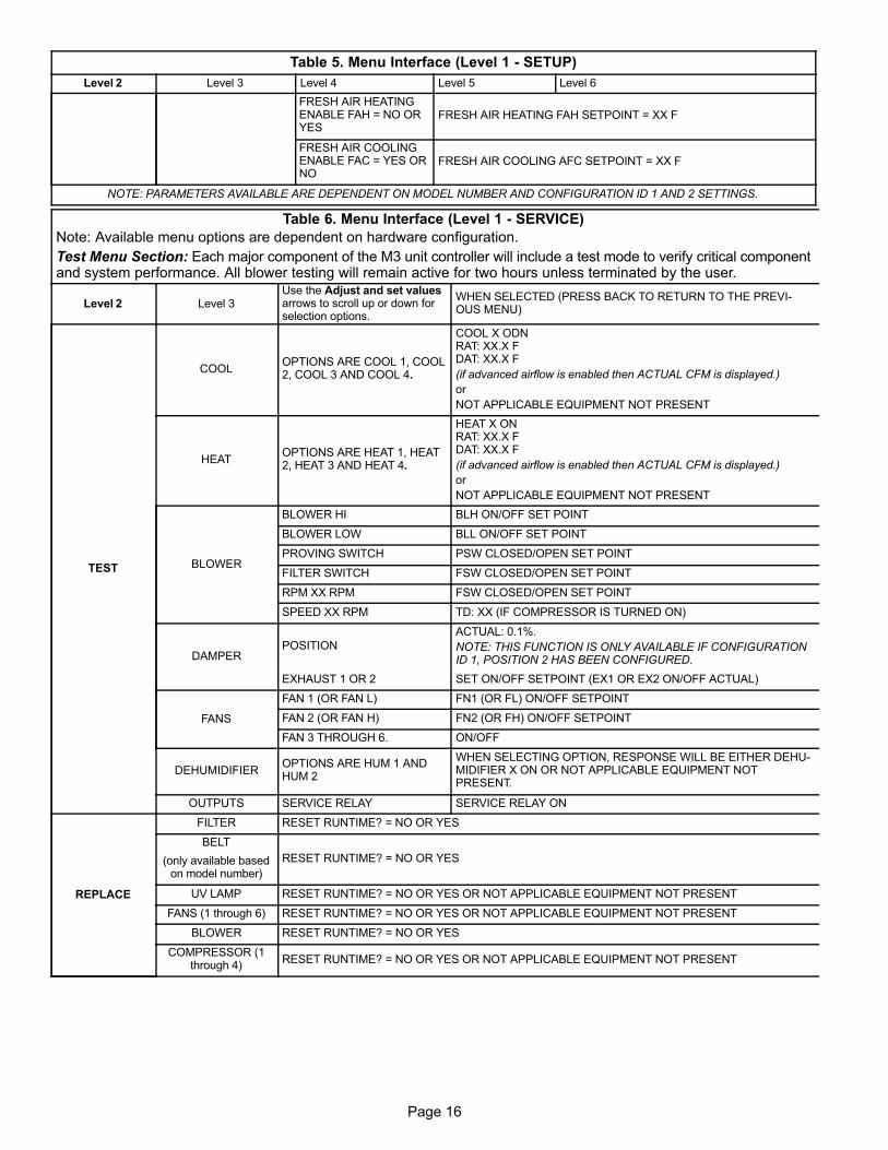
Page 16
Table 5. Menu Interface (Level 1 - SETUP)
Level 2 Level 6Level 5Level 4Level 3
FRESH AIR HEATINGENABLE FAH = NO ORYES
FRESH AIR HEATING FAH SETPOINT = XX F
FRESH AIR COOLINGENABLE FAC = YES ORNO
FRESH AIR COOLING AFC SETPOINT = XX F
NOTE: PARAMETERS AVAILABLE ARE DEPENDENT ON MODEL NUMBER AND CONFIGURATION ID 1 AND 2 SETTINGS.
Table 6. Menu Interface (Level 1 - SERVICE)
Note: Available menu options are dependent on hardware configuration.
Test Menu Section: Each major component of the M3 unit controller will include a test mode to verify critical componentand system performance. All blower testing will remain active for two hours unless terminated by the user.
Level 2 Level 3Use the Adjust and set valuesarrows to scroll up or down forselection options.
WHEN SELECTED (PRESS BACK TO RETURN TO THE PREVIOUS MENU)
TEST
COOLOPTIONS ARE COOL 1, COOL2, COOL 3 AND COOL 4.
COOL X ODNRAT: XX.X FDAT: XX.X F
(if advanced airflow is enabled then ACTUAL CFM is displayed.)
or
NOT APPLICABLE EQUIPMENT NOT PRESENT
HEATOPTIONS ARE HEAT 1, HEAT2, HEAT 3 AND HEAT 4.
HEAT X ONRAT: XX.X FDAT: XX.X F
(if advanced airflow is enabled then ACTUAL CFM is displayed.)
or
NOT APPLICABLE EQUIPMENT NOT PRESENT
BLOWER
BLOWER HI BLH ON/OFF SET POINT
BLOWER LOW BLL ON/OFF SET POINT
PROVING SWITCH PSW CLOSED/OPEN SET POINT
FILTER SWITCH FSW CLOSED/OPEN SET POINT
RPM XX RPM FSW CLOSED/OPEN SET POINT
SPEED XX RPM TD: XX (IF COMPRESSOR IS TURNED ON)
DAMPERPOSITION
ACTUAL: 0.1%.
NOTE: THIS FUNCTION IS ONLY AVAILABLE IF CONFIGURATIONID 1, POSITION 2 HAS BEEN CONFIGURED.
EXHAUST 1 OR 2 SET ON/OFF SETPOINT (EX1 OR EX2 ON/OFF ACTUAL)
FANS
FAN 1 (OR FAN L) FN1 (OR FL) ON/OFF SETPOINT
FAN 2 (OR FAN H) FN2 (OR FH) ON/OFF SETPOINT
FAN 3 THROUGH 6. ON/OFF
DEHUMIDIFIEROPTIONS ARE HUM 1 ANDHUM 2
WHEN SELECTING OPTION, RESPONSE WILL BE EITHER DEHUMIDIFIER X ON OR NOT APPLICABLE EQUIPMENT NOTPRESENT.
OUTPUTS SERVICE RELAY SERVICE RELAY ON
REPLACE
FILTER RESET RUNTIME? = NO OR YES
BELT
(only available basedon model number)
RESET RUNTIME? = NO OR YES
UV LAMP RESET RUNTIME? = NO OR YES OR NOT APPLICABLE EQUIPMENT NOT PRESENT
FANS (1 through 6) RESET RUNTIME? = NO OR YES OR NOT APPLICABLE EQUIPMENT NOT PRESENT
BLOWER RESET RUNTIME? = NO OR YES
COMPRESSOR (1through 4)
RESET RUNTIME? = NO OR YES OR NOT APPLICABLE EQUIPMENT NOT PRESENT

Page 17
Page 17
Table 6. Menu Interface (Level 1 - SERVICE)
Note: Available menu options are dependent on hardware configuration.
Test Menu Section: Each major component of the M3 unit controller will include a test mode to verify critical componentand system performance. All blower testing will remain active for two hours unless terminated by the user.
Level 2 Level 3Use the Adjust and set valuesarrows to scroll up or down forselection options.
WHEN SELECTED (PRESS BACK TO RETURN TO THE PREVIOUS MENU)
REPORT
USB SERVICEREPORT
USB SERVICE REPORT = DEFAULT VALVE IS THE SERIAL NUMBER IF SET. OTHERWISE IT WILLBE 123456789. CAN BE RENAMED BY USER. MAXIMUM 18 CHARACTERS.
USB ADV AIRFLOWRPT
USB ADVANCED AIRFLOWREPORT = START USB REPORT OR USB REPORTDONE.
START USB REPORT = SAF_RPT (DEFAULT) AND CAN BE RENAMED BY USER. MAXIMUM 18 CHARACTERS.
SAVE USERPROFILE
SAVE USER PROFILE = YES OR NO
LOAD USERPROFILE
LOAD USER PROFILE = YES OR NO
USB PROFILE SAVEUSB PROFILE SAVE = 1234 UNLESS CATALOG NUMBER IS SET. DEFAULT IS CATALOG NUMBER.CAN BE RENAMED BY USER. MAXIMUM 18 CHARACTERS.
USB PROFILE LOAD
USB PROFILE LOAD =1234XXXXXXXXXXX (USERASSIGNED NAME AS SPECIFICED. TYPICALLY CATALOG NUMBER.
WILL LOAD PREVIOUSLY SAVED USB PROFILE.
LOAD FACTORYPROF
LOAD FACTORY PROF = YES OR NO
LOG SERVICEEVENT
LOG SERVICE EVENT = YES OR NO
SOFTWAREUPDATE
SOFTWAREUPDATE
SOFTWARE UPDATE (EITHERTHE UPDATE WILL BE SUCCESSFUL OR THE FOLLOWING MESSAGES WILL APPEAR. SW UPDATE FAILEDOR SW UPDATE FILE NOTFOUND.
NOTE: IF USB FLASH DRIVE IS NOT INSTALLED OR THE M3 UNITCONTROLLER CANNOT READ THE FLASH MEDIA, A MESSAGEWILL APPEAR “NOT APPLICABLE EQUIPMENT NOT PRESENT.”
OFFLINE
CLEAR DELAYS CLEAR DELAYS = YES OR NO.
RESETCONTROLLER
RESET CONTROLLER = YESOR NO.
NOTE: THIS REBOOTS THE M3 CONTROLLER. NO CONFIGURATION SETTINGS ARE CHANGED.
CONTROLLERLOCKOUT
CONTROLLER LOCKOUT = YES OR NO.
NOTE: PARAMETERS AVAILABLE ARE DEPENDENT ON MODEL NUMBER AND CONFIGURATION ID 1 AND 2 SETTINGS.
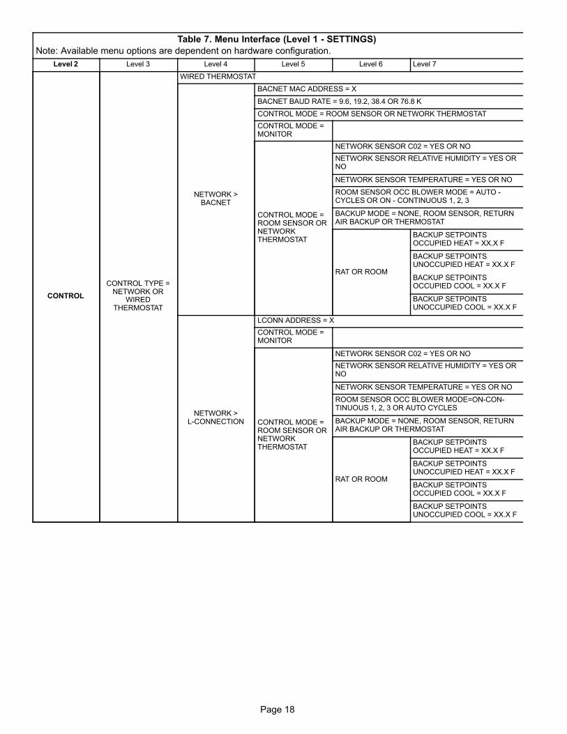
Page 18
Table 7. Menu Interface (Level 1 - SETTINGS)
Note: Available menu options are dependent on hardware configuration.
Level 2 Level 3 Level 4 Level 5 Level 6 Level 7
CONTROL
CONTROL TYPE =NETWORK OR
WIREDTHERMOSTAT
WIRED THERMOSTAT
NETWORK >BACNET
BACNET MAC ADDRESS = X
BACNET BAUD RATE = 9.6, 19.2, 38.4 OR 76.8 K
CONTROL MODE = ROOM SENSOR OR NETWORK THERMOSTAT
CONTROL MODE =MONITOR
CONTROL MODE =ROOM SENSOR ORNETWORKTHERMOSTAT
NETWORK SENSOR C02 = YES OR NO
NETWORK SENSOR RELATIVE HUMIDITY = YES ORNO
NETWORK SENSOR TEMPERATURE = YES OR NO
ROOM SENSOR OCC BLOWER MODE = AUTO -CYCLES OR ON - CONTINUOUS 1, 2, 3
BACKUP MODE = NONE, ROOM SENSOR, RETURNAIR BACKUP OR THERMOSTAT
RAT OR ROOM
BACKUP SETPOINTSOCCUPIED HEAT = XX.X F
BACKUP SETPOINTSUNOCCUPIED HEAT = XX.X F
BACKUP SETPOINTSOCCUPIED COOL = XX.X F
BACKUP SETPOINTSUNOCCUPIED COOL = XX.X F
NETWORK >L-CONNECTION
LCONN ADDRESS = X
CONTROL MODE =MONITOR
CONTROL MODE =ROOM SENSOR ORNETWORKTHERMOSTAT
NETWORK SENSOR C02 = YES OR NO
NETWORK SENSOR RELATIVE HUMIDITY = YES ORNO
NETWORK SENSOR TEMPERATURE = YES OR NO
ROOM SENSOR OCC BLOWER MODE=ON-CONTINUOUS 1, 2, 3 OR AUTO CYCLES
BACKUP MODE = NONE, ROOM SENSOR, RETURNAIR BACKUP OR THERMOSTAT
RAT OR ROOM
BACKUP SETPOINTSOCCUPIED HEAT = XX.X F
BACKUP SETPOINTSUNOCCUPIED HEAT = XX.X F
BACKUP SETPOINTSOCCUPIED COOL = XX.X F
BACKUP SETPOINTSUNOCCUPIED COOL = XX.X F
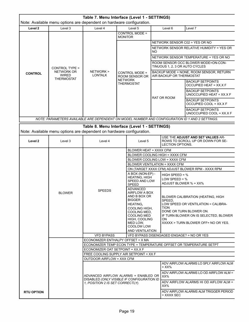
Page 19
Page 19
Table 7. Menu Interface (Level 1 - SETTINGS)
Note: Available menu options are dependent on hardware configuration.
Level 2 Level 7Level 6Level 5Level 4Level 3
CONTROL
CONTROL TYPE =NETWORK OR
WIREDTHERMOSTAT
NETWORK >LONTALK
CONTROL MODE =MONITOR
CONTROL MODE =ROOM SENSOR ORNETWORKTHERMOSTAT
NETWORK SENSOR C02 = YES OR NO
NETWORK SENSOR RELATIVE HUMIDITY = YES ORNO
NETWORK SENSOR TEMPERATURE = YES OR NO
ROOM SENSOR OCC BLOWER MODE=ON-CONTINUOUS 1, 2, 3 OR AUTO CYCLES
BACKUP MODE = NONE, ROOM SENSOR, RETURNAIR BACKUP OR THERMOSTAT
RAT OR ROOM
BACKUP SETPOINTSOCCUPIED HEAT = XX.X F
BACKUP SETPOINTSUNOCCUPIED HEAT = XX.X F
BACKUP SETPOINTSOCCUPIED COOL = XX.X F
BACKUP SETPOINTSUNOCCUPIED COOL = XX.X F
NOTE: PARAMETERS AVAILABLE ARE DEPENDENT ON MODEL NUMBER AND CONFIGURATION ID 1 AND 2 SETTINGS.
Table 8. Menu Interface (Level 1 - SETTINGS)
Note: Available menu options are dependent on hardware configuration.
Level 2 Level 3 Level 4 Level 5USE THE ADJUST AND SET VALUES ARROWS TO SCROLL UP OR DOWN FOR SELECTION OPTIONS.
RTU OPTION
BLOWERSPEEDS
BLOWER HEAT = XXXX CFM
BLOWER COOLING HIGH = XXXX CFM
BLOWER COOLING LOW = XXXX CFM
BLOWER VENTILATION = XXXX CFM
ON (TARGET XXXX CFM) ADJUST BLOWER RPM - XXXX RPM
A BOX (NON-EP) -HEATING, HIGHSPEED AND LOWSPEED
HIGH SPEED = %
LOW SPEED = %
ADJUST BLOWER % = XX%
ADVANCEDAIRFLOW A BOXAND B BOX ORBIGGER
HEATING,
COOLING HIGH,COOLING MED,COOLING MEDHIGH, COOLINGMED LOW,COOLOW LOW
AND VENTILATION
BLOWER CALIBRATION (HEATING, HIGHSPEED,LOW SPEED OR VENTILATION = CALIBRATIONDONE OR TURN BLOWER ON.
IF TURN BLOWER ON IS SELECTED, BLOWERONXXXXX > TURN BLOWER OFF= NO OR YES.
VFD BYPASS VFD BYPASS DISENGAGED ENGAGE? = NO OR YES
ECONOMIZER ENTHALPY OFFSET = X MA
ECONOMIZER TEMP ECON TYPE = TEMPERATURE OFFSET OR TEMPERATURE SETPT
ECONOMIZER OAT SETPOINT = XX.X F
FREE COOLING SUPPLY AIR SETPOINT = XX F
OUTDOOR AIRFLOW = XXX CFM
ADVANCED AIRFLOW ALARMS = ENABLED ORDISABLED (ONLY VISIBLE IF CONFIGURATION ID1, POSITION 2 IS SET CORRECTLY).
ADV AIRFLOW ALARMS LO SPLY AIRFLOW ALM= XX%
ADV AIRFLOW ALARMS LO OD AIRFLOW ALM =XX%
ADV AIRFLOW ALARMS HI OD AIFLOW ALM =XX%
ADV AIRFLOW ALARMS ALM TRIGGER PERIOD= XXXX SEC
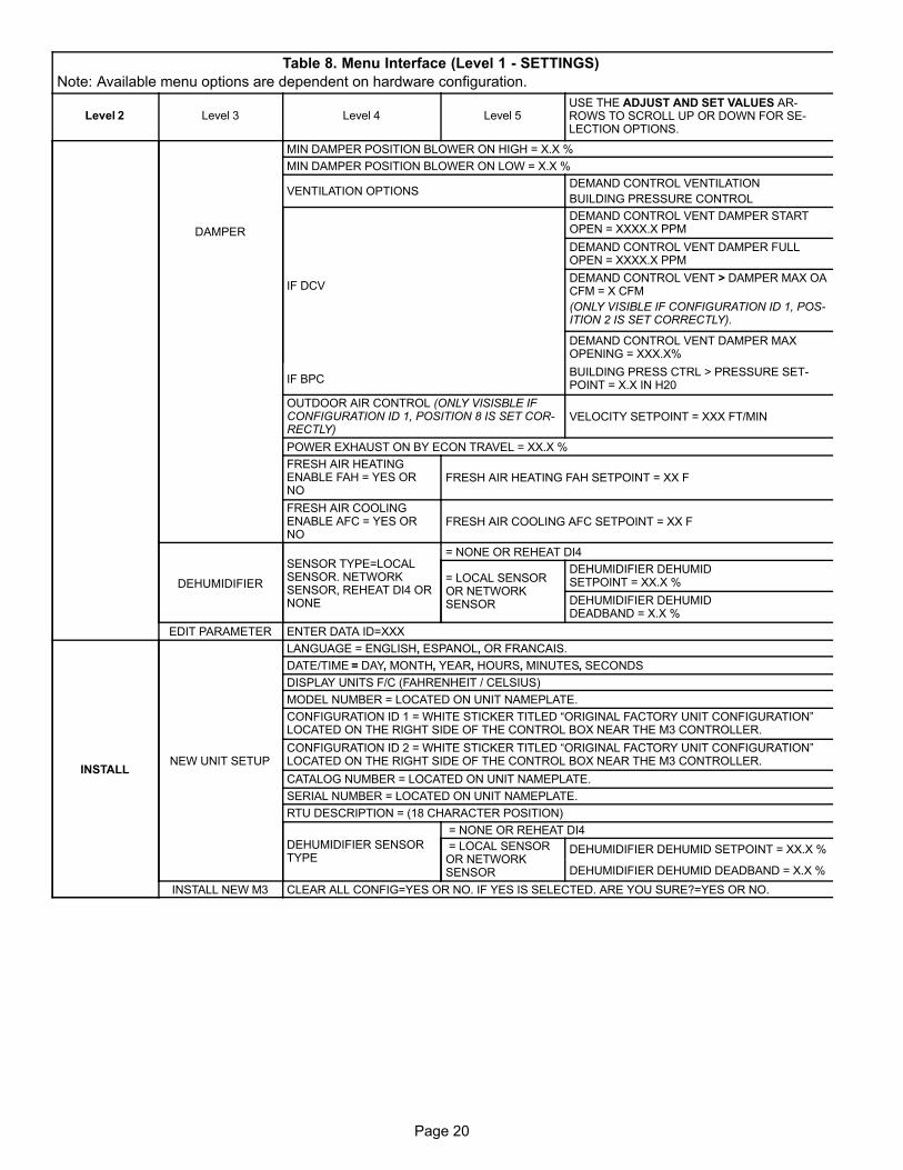
Page 20
Table 8. Menu Interface (Level 1 - SETTINGS)
Note: Available menu options are dependent on hardware configuration.
Level 2USE THE ADJUST AND SET VALUES ARROWS TO SCROLL UP OR DOWN FOR SELECTION OPTIONS.
Level 5Level 4Level 3
DAMPER
MIN DAMPER POSITION BLOWER ON HIGH = X.X %
MIN DAMPER POSITION BLOWER ON LOW = X.X %
VENTILATION OPTIONSDEMAND CONTROL VENTILATION
BUILDING PRESSURE CONTROL
IF DCV
DEMAND CONTROL VENT DAMPER STARTOPEN = XXXX.X PPM
DEMAND CONTROL VENT DAMPER FULLOPEN = XXXX.X PPM
DEMAND CONTROL VENT > DAMPER MAX OACFM = X CFM
(ONLY VISIBLE IF CONFIGURATION ID 1, POSITION 2 IS SET CORRECTLY).
DEMAND CONTROL VENT DAMPER MAXOPENING = XXX.X%
IF BPCBUILDING PRESS CTRL > PRESSURE SETPOINT = X.X IN H20
OUTDOOR AIR CONTROL (ONLY VISISBLE IFCONFIGURATION ID 1, POSITION 8 IS SET CORRECTLY)
VELOCITY SETPOINT = XXX FT/MIN
POWER EXHAUST ON BY ECON TRAVEL = XX.X %
FRESH AIR HEATINGENABLE FAH = YES ORNO
FRESH AIR HEATING FAH SETPOINT = XX F
FRESH AIR COOLINGENABLE AFC = YES ORNO
FRESH AIR COOLING AFC SETPOINT = XX F
DEHUMIDIFIER
SENSOR TYPE=LOCALSENSOR. NETWORKSENSOR, REHEAT DI4 ORNONE
= NONE OR REHEAT DI4
= LOCAL SENSOROR NETWORKSENSOR
DEHUMIDIFIER DEHUMID SETPOINT = XX.X %
DEHUMIDIFIER DEHUMID DEADBAND = X.X %
EDIT PARAMETER ENTER DATA ID=XXX
INSTALLNEW UNIT SETUP
LANGUAGE = ENGLISH, ESPANOL, OR FRANCAIS.
DATE/TIME = DAY, MONTH, YEAR, HOURS, MINUTES, SECONDS
DISPLAY UNITS F/C (FAHRENHEIT / CELSIUS)
MODEL NUMBER = LOCATED ON UNIT NAMEPLATE.
CONFIGURATION ID 1 = WHITE STICKER TITLED “ORIGINAL FACTORY UNIT CONFIGURATION”LOCATED ON THE RIGHT SIDE OF THE CONTROL BOX NEAR THE M3 CONTROLLER.
CONFIGURATION ID 2 = WHITE STICKER TITLED “ORIGINAL FACTORY UNIT CONFIGURATION”LOCATED ON THE RIGHT SIDE OF THE CONTROL BOX NEAR THE M3 CONTROLLER.
CATALOG NUMBER = LOCATED ON UNIT NAMEPLATE.
SERIAL NUMBER = LOCATED ON UNIT NAMEPLATE.
RTU DESCRIPTION = (18 CHARACTER POSITION)
DEHUMIDIFIER SENSORTYPE
= NONE OR REHEAT DI4
= LOCAL SENSOROR NETWORKSENSOR
DEHUMIDIFIER DEHUMID SETPOINT = XX.X %
DEHUMIDIFIER DEHUMID DEADBAND = X.X %
INSTALL NEW M3 CLEAR ALL CONFIG=YES OR NO. IF YES IS SELECTED. ARE YOU SURE?=YES OR NO.
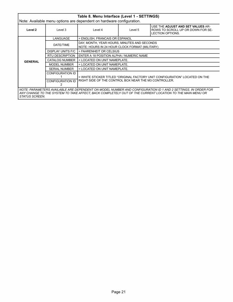
Page 21
Page 21
Table 8. Menu Interface (Level 1 - SETTINGS)
Note: Available menu options are dependent on hardware configuration.
Level 2USE THE ADJUST AND SET VALUES ARROWS TO SCROLL UP OR DOWN FOR SELECTION OPTIONS.
Level 5Level 4Level 3
GENERAL
LANGUAGE = ENGLISH, FRANCAIS OR ESPANOL
DATE/TIMEDAY, MONTH, YEAR HOURS, MINUTES AND SECONDS
NOTE: HOURS IN 24 HOUR CLOCK FORMAT (MILITARY)
DISPLAY UNITS F/C = FAHRENHEIT OR CELSIUS
RTU DESCRIPTION ENTER A 18 POSITION ALPHA / NUMERIC NAME
CATALOG NUMBER = LOCATED ON UNIT NAMEPLATE.
MODEL NUMBER = LOCATED ON UNIT NAMEPLATE.
SERIAL NUMBER = LOCATED ON UNIT NAMEPLATE.
CONFIGURATION ID1 = WHITE STICKER TITLED “ORIGINAL FACTORY UNIT CONFIGURATION” LOCATED ON THE
RIGHT SIDE OF THE CONTROL BOX NEAR THE M3 CONTROLLER.CONFIGURATION ID2
NOTE: PARAMETERS AVAILABLE ARE DEPENDENT ON MODEL NUMBER AND CONFIGURATION ID 1 AND 2 SETTINGS. IN ORDER FORANY CHANGE TO THE SYSTEM TO TAKE AFFECT, BACK COMPLETELY OUT OF THE CURRENT LOCATION TO THE MAIN MENU ORSTATUS SCREEN.

Page 22
Blower Operation with Effective Occupancy
This section describes how network occupancy signals arecombined to produce effective occupancy.
The blower runs to service heat and cool demands,regardless of the space occupancy. However when there isno heating or cooling demand there are options for how theblower should operate in conjunction with occupancy signalsto keep the space ventilated, or the air stirred.
1. California Energy Commission Title 24
The legacy option settings for OCC Blower Mode are
AUTO CYCLES or ON-CONTINUOUS 1. These
settings govern whether the blower runs continuously
when the space is considered occupied, or cycles on/off
with the heating and cooling demand.
To comply with the California Energy Commission Title
24 standard there are two additional values for OCC
Blower Mode which are ON-CONTINUOUS 2 and
ON-CONTINUOUS 3. See table 9 for their descriptions.
Table 9. Blower Operation Description
OCC BlowerMode
Description
AUTOCYCLES
Blower cycles on/off with demand. (Legacy usage.)
ON-CONTINUOUS
1
Blower runs when either the occupancy sensor orschedule, or both, indicates occupied. (Legacy usage.)
ON-CONTINUOUS
2
Blower runs when both the occupancy sensor andschedule indicate occupied.
ON-CONTINUOUS
3
The same as option 2, but blower runs for 30 minutesand is off for 90 minutes when schedule is occupiedbut the occupancy sensor isnot occupied.
A. LonTalk, BACnet and L Connection: These twonew options are available when using these networkstypes that supplies a room occupancy signal (inaddition to the scheduled occupancy).
NOTE: For L Connection the same two options are
also available when using an optional room
occupancy sensor. If a room occupancy sensor is not
physically installed and configured for the network,
then the only options available for OCC Blower
Mode are AUTO CYCLES or ON-CONTINUOUS 1.
B. RTU Standalone: Since a room occupancy sensorcannot be used in this configuration, then the onlyoptions for OCC Blower Mode are AUTO CYCLESor ON-CONTINUOUS 1.
2. Enabling Network Type
To enable the network module, go to SETUP > INSTALL
and run the setup wizard. When Configuration ID 1
appears on the screen, configure position 5 to one of the
applicable network types. N = Not Installed, B = BACnet
and L = LonTalk.
3. Menu Setup Procedure Method for OCC BlowerMode
These blower control options are handled by the OCC
Blower Mode. These setting and be changed using the
following menu path:
Go to SETUP > NETWORK INTEGRATION >
NETWORK = “BACNET, LONTALK or L
CONNECTION” > (additional prompts concerning
network configuration and sensor types will be
asked) CONTROL MODE = ROOM SENSOR > ROOM
SENSOR OCC BLOWER MODE = (see table 9)
Table 10. BACnet Occupancy Points
BACnet Value
ManualOccupancy Override Control
AO 103
0: space occupied
1: space unoccupied
2: refresh space occupied override timer
3255: auto; clear timer and return to scheduler
ScheduleOccupancy Scheduler Control
AO 104
0: space occupied
1255: space unoccupied
SensorOccupancy Sensor Input
AO 107
0: space occupied
1: space unoccupied
2255: auto; return to occupancy scheduler state
EffectiveOccupancy
Effective OccupancyAI 241
0: space occupied
1: space unoccupied
2: space occupied (timed override)
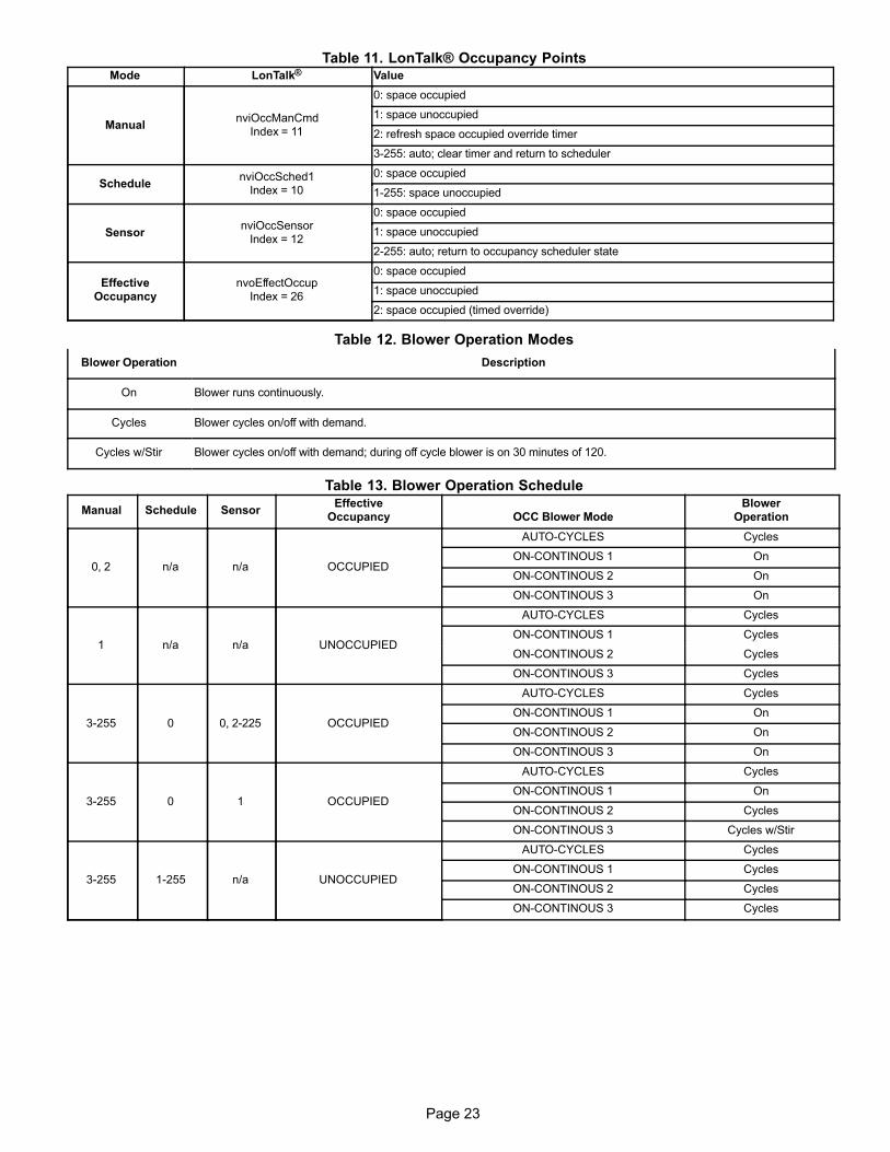
Page 23
Page 23
Table 11. LonTalk® Occupancy PointsMode LonTalk® Value
ManualnviOccManCmd
Index = 11
0: space occupied
1: space unoccupied
2: refresh space occupied override timer
3255: auto; clear timer and return to scheduler
SchedulenviOccSched1
Index = 10
0: space occupied
1255: space unoccupied
SensornviOccSensor
Index = 12
0: space occupied
1: space unoccupied
2255: auto; return to occupancy scheduler state
EffectiveOccupancy
nvoEffectOccupIndex = 26
0: space occupied
1: space unoccupied
2: space occupied (timed override)
Table 12. Blower Operation Modes
Blower Operation Description
On Blower runs continuously.
Cycles Blower cycles on/off with demand.
Cycles w/Stir Blower cycles on/off with demand; during off cycle blower is on 30 minutes of 120.
Table 13. Blower Operation Schedule
Manual Schedule SensorEffective
Occupancy OCC Blower ModeBlower
Operation
0, 2 n/a n/a OCCUPIED
AUTO-CYCLES Cycles
ON-CONTINOUS 1 On
ON-CONTINOUS 2 On
ON-CONTINOUS 3 On
1 n/a n/a UNOCCUPIED
AUTO-CYCLES Cycles
ON-CONTINOUS 1 Cycles
ON-CONTINOUS 2 Cycles
ON-CONTINOUS 3 Cycles
3255 0 0, 2-225 OCCUPIED
AUTO-CYCLES Cycles
ON-CONTINOUS 1 On
ON-CONTINOUS 2 On
ON-CONTINOUS 3 On
3255 0 1 OCCUPIED
AUTO-CYCLES Cycles
ON-CONTINOUS 1 On
ON-CONTINOUS 2 Cycles
ON-CONTINOUS 3 Cycles w/Stir
3255 1255 n/a UNOCCUPIED
AUTO-CYCLES Cycles
ON-CONTINOUS 1 Cycles
ON-CONTINOUS 2 Cycles
ON-CONTINOUS 3 Cycles
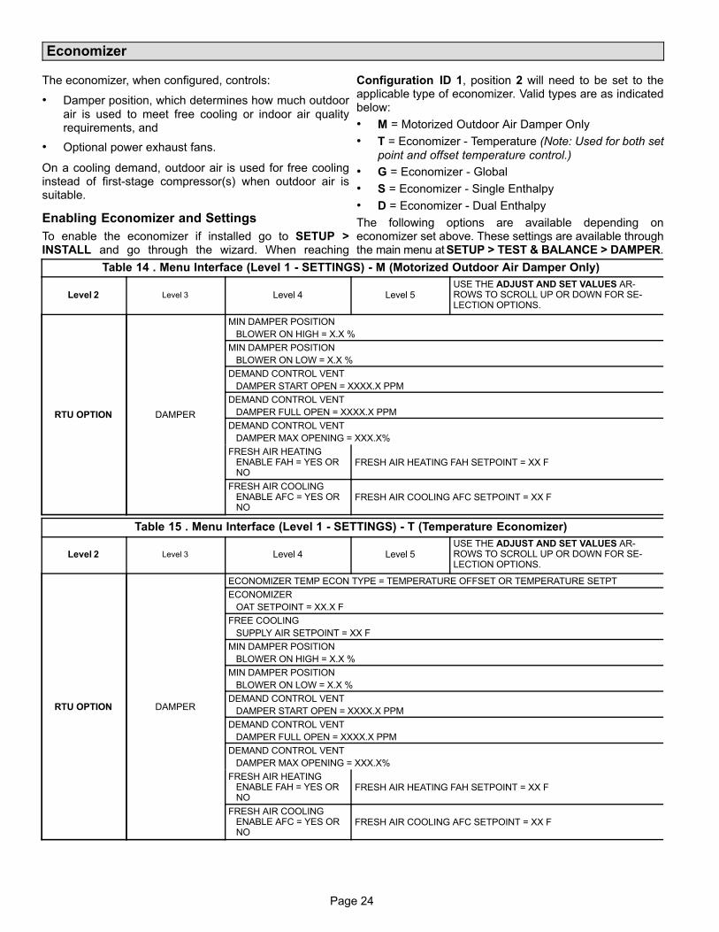
Page 24
Economizer
The economizer, when configured, controls:
� Damper position, which determines how much outdoor
air is used to meet free cooling or indoor air qualityrequirements, and
� Optional power exhaust fans.
On a cooling demand, outdoor air is used for free coolinginstead of first-stage compressor(s) when outdoor air issuitable.
Enabling Economizer and Settings
To enable the economizer if installed go to SETUP >INSTALL and go through the wizard. When reaching
Configuration ID 1, position 2 will need to be set to theapplicable type of economizer. Valid types are as indicatedbelow:
� M = Motorized Outdoor Air Damper Only
� T = Economizer - Temperature (Note: Used for both set
point and offset temperature control.)
� G = Economizer - Global
� S = Economizer - Single Enthalpy
� D = Economizer - Dual Enthalpy
The following options are available depending oneconomizer set above. These settings are available throughthe main menu at SETUP > TEST & BALANCE > DAMPER.
Table 14 . Menu Interface (Level 1 - SETTINGS) - M (Motorized Outdoor Air Damper Only)
Level 2 Level 3 Level 4 Level 5USE THE ADJUST AND SET VALUES ARROWS TO SCROLL UP OR DOWN FOR SELECTION OPTIONS.
RTU OPTION DAMPER
MIN DAMPER POSITION
BLOWER ON HIGH = X.X %
MIN DAMPER POSITION
BLOWER ON LOW = X.X %
DEMAND CONTROL VENT
DAMPER START OPEN = XXXX.X PPM
DEMAND CONTROL VENT
DAMPER FULL OPEN = XXXX.X PPM
DEMAND CONTROL VENT
DAMPER MAX OPENING = XXX.X%
FRESH AIR HEATING ENABLE FAH = YES OR NO
FRESH AIR HEATING FAH SETPOINT = XX F
FRESH AIR COOLING ENABLE AFC = YES OR NO
FRESH AIR COOLING AFC SETPOINT = XX F
Table 15 . Menu Interface (Level 1 - SETTINGS) - T (Temperature Economizer)
Level 2 Level 3 Level 4 Level 5USE THE ADJUST AND SET VALUES ARROWS TO SCROLL UP OR DOWN FOR SELECTION OPTIONS.
RTU OPTION DAMPER
ECONOMIZER TEMP ECON TYPE = TEMPERATURE OFFSET OR TEMPERATURE SETPT
ECONOMIZER
OAT SETPOINT = XX.X F
FREE COOLING
SUPPLY AIR SETPOINT = XX F
MIN DAMPER POSITION
BLOWER ON HIGH = X.X %
MIN DAMPER POSITION
BLOWER ON LOW = X.X %
DEMAND CONTROL VENT
DAMPER START OPEN = XXXX.X PPM
DEMAND CONTROL VENT
DAMPER FULL OPEN = XXXX.X PPM
DEMAND CONTROL VENT
DAMPER MAX OPENING = XXX.X%
FRESH AIR HEATING ENABLE FAH = YES OR NO
FRESH AIR HEATING FAH SETPOINT = XX F
FRESH AIR COOLING ENABLE AFC = YES OR NO
FRESH AIR COOLING AFC SETPOINT = XX F
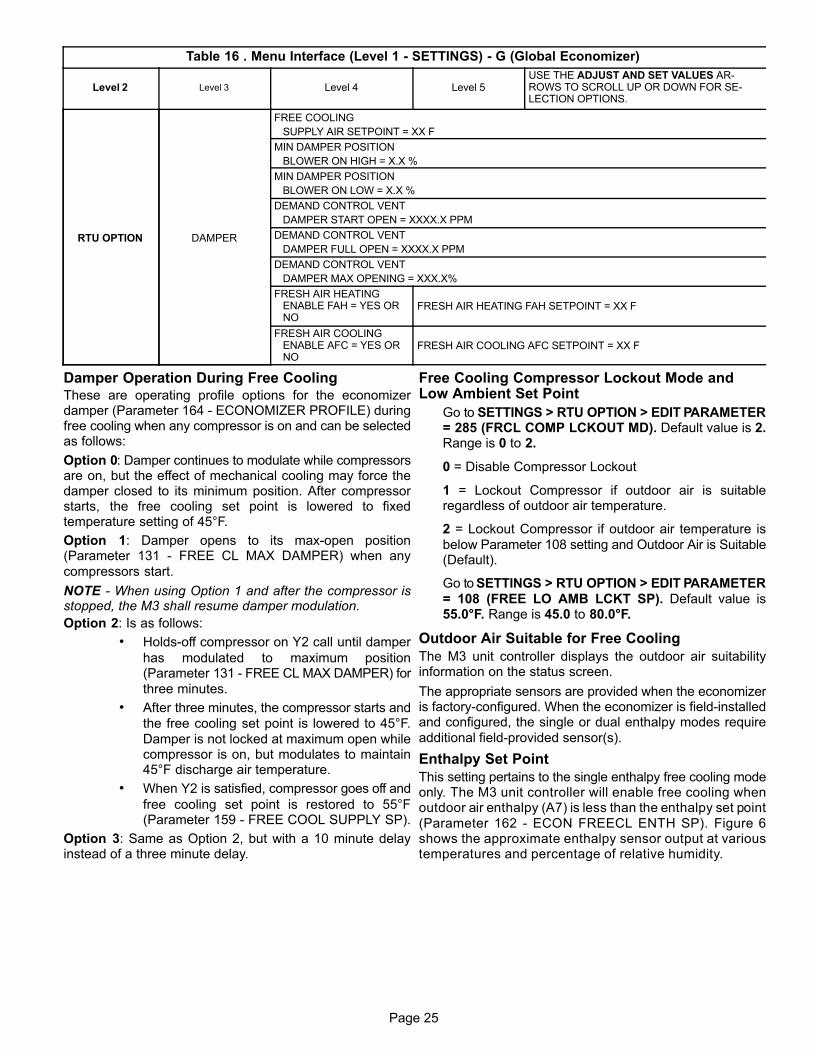
Page 25
Page 25
Table 16 . Menu Interface (Level 1 - SETTINGS) - G (Global Economizer)
Level 2 Level 3 Level 4 Level 5USE THE ADJUST AND SET VALUES ARROWS TO SCROLL UP OR DOWN FOR SELECTION OPTIONS.
RTU OPTION DAMPER
FREE COOLING
SUPPLY AIR SETPOINT = XX F
MIN DAMPER POSITION
BLOWER ON HIGH = X.X %
MIN DAMPER POSITION
BLOWER ON LOW = X.X %
DEMAND CONTROL VENT
DAMPER START OPEN = XXXX.X PPM
DEMAND CONTROL VENT
DAMPER FULL OPEN = XXXX.X PPM
DEMAND CONTROL VENT
DAMPER MAX OPENING = XXX.X%
FRESH AIR HEATING ENABLE FAH = YES OR NO
FRESH AIR HEATING FAH SETPOINT = XX F
FRESH AIR COOLING ENABLE AFC = YES OR NO
FRESH AIR COOLING AFC SETPOINT = XX F
Damper Operation During Free Cooling These are operating profile options for the economizerdamper (Parameter 164 - ECONOMIZER PROFILE) duringfree cooling when any compressor is on and can be selectedas follows:
Option 0: Damper continues to modulate while compressorsare on, but the effect of mechanical cooling may force thedamper closed to its minimum position. After compressorstarts, the free cooling set point is lowered to fixedtemperature setting of 45°F.
Option 1: Damper opens to its maxopen position(Parameter 131 - FREE CL MAX DAMPER) when any
compressors start.
NOTE - When using Option 1 and after the compressor isstopped, the M3 shall resume damper modulation.
Option 2: Is as follows:
� Holdsoff compressor on Y2 call until damper
has modulated to maximum position(Parameter 131 - FREE CL MAX DAMPER) for
three minutes.
� After three minutes, the compressor starts and
the free cooling set point is lowered to 45°F.
Damper is not locked at maximum open whilecompressor is on, but modulates to maintain45°F discharge air temperature.
� When Y2 is satisfied, compressor goes off and
free cooling set point is restored to 55°F(Parameter 159 - FREE COOL SUPPLY SP).
Option 3: Same as Option 2, but with a 10 minute delayinstead of a three minute delay.
Free Cooling Compressor Lockout Mode andLow Ambient Set Point
Go to SETTINGS > RTU OPTION > EDIT PARAMETER= 285 (FRCL COMP LCKOUT MD). Default value is 2.Range is 0 to 2.
0 = Disable Compressor Lockout
1 = Lockout Compressor if outdoor air is suitableregardless of outdoor air temperature.
2 = Lockout Compressor if outdoor air temperature is
below Parameter 108 setting and Outdoor Air is Suitable(Default).
Go to SETTINGS > RTU OPTION > EDIT PARAMETER
= 108 (FREE LO AMB LCKT SP). Default value is55.0°F. Range is 45.0 to 80.0°F.
Outdoor Air Suitable for Free Cooling
The M3 unit controller displays the outdoor air suitabilityinformation on the status screen.
The appropriate sensors are provided when the economizeris factory-configured. When the economizer is field-installedand configured, the single or dual enthalpy modes require
additional field-provided sensor(s).
Enthalpy Set Point
This setting pertains to the single enthalpy free cooling modeonly. The M3 unit controller will enable free cooling whenoutdoor air enthalpy (A7) is less than the enthalpy set point
(Parameter 162 - ECON FREECL ENTH SP). Figure 6shows the approximate enthalpy sensor output at varioustemperatures and percentage of relative humidity.

Page 26
40°F 50°F 60°F 70°F 80°F 90°F 100°F
30
20
10
40
50
60
70
80
90
100
Figure 6. Enthalpy Sensor Output Current Honeywell C7400
Table 17 . Menu Interface (Level 1 - SETTINGS) - Single Enthalpy
The following settings are available when Configuration ID 1, position 2 is set to S (Single Enthalpy)
Level 2 Level 3 Level 4USE THE ADJUST AND SET VALUES ARROWS TO SCROLL UP ORDOWN FOR SELECTION OPTIONS.
RTU OPTION DAMPER
ECONOMIZER ENTHALPY SETPOINT = XX.X MA
ENTHALPY SET POINT MA SETTING
73°F 12.0
70°F 13.6
67°F 15.5
63°F 17.6
FREE COOLING
SUPPLY AIR SETPOINT = XX.X F
CLIMATE ZONE SINGLE SENSIBLE
1, 3, 5, 11-16 75.0°F
2, 4, 10 73.0°F
6, 8, 9 71.0°F
7 69.0°F
MIN DAMPER POSITION
BLOWER ON HIGH = X.X %
MIN DAMPER POSITION
BLOWER ON LOW = X.X %
DEMAND CONTROL VENT
DAMPER START OPEN = XXXX.X PPM
DEMAND CONTROL VENT
DAMPER FULL OPEN = XXXX.X PPM
DEMAND CONTROL VENT
DAMPER MAX OPENING = XXX.X%
FRESH AIR HEATING ENABLE FAH = YES OR NO
FRESH AIR HEATING FAH SETPOINT = XX F
FRESH AIR COOLING ENABLE AFC = YES OR NO
FRESH AIR COOLING AFC SETPOINT = XX F

Page 27
Page 27
Table 18 . Menu Interface (Level 1 - SETTINGS) - Dual Enthalpy
The following settings are available when Configuration ID 1, position 2 is set to D (Dual Enthalpy)
Level 2 Level 3 Level 4USE THE ADJUST AND SET VALUES ARROWS TO SCROLL UP ORDOWN FOR SELECTION OPTIONS.
RTU OPTION DAMPER
ECONOMIZER ENTHALPY OFFSET = X.XX MA
TEMP OFFSET* RELATIVE HUMIDITY °F OFFSET %** MA SETTING
2 6 1.0
3.5 12 2.0
5.3 18 3.0
7 24 4.0
* AT A CONSTANT RELATIVE HUMIDITY.
** AT A CONSTANT TEMPERATURE
FREE COOLING
SUPPLY AIR SETPOINT = XX F
CLIMATE ZONE SINGLE SENSIBLE
1, 3, 5, 11-16 75°F
2, 4, 10 73°F
6, 8, 9 71°F
7 69°F
MIN DAMPER POSITION
BLOWER ON HIGH = X.X %
MIN DAMPER POSITION
BLOWER ON LOW = X.X %
DEMAND CONTROL VENT
DAMPER START OPEN = XXXX.X PPM
DEMAND CONTROL VENT
DAMPER FULL OPEN = XXXX.X PPM
DEMAND CONTROL VENT
DAMPER MAX OPENING = XXX.X%
FRESH AIR HEATING ENABLE FAH = YES OR NO
FRESH AIR HEATING FAH SETPOINT = XX F
FRESH AIR COOLING ENABLE AFC = YES OR NO
FRESH AIR COOLING AFC SETPOINT = XX F
Free Cooling Damper Maximum Position
Damper Maximum position for free cooling is by default set to100%. To modify this settings, use the following path:
SETTINGS > RTU OPTION > EDIT PARAMETER - 131(FREE CL MAX DAMPER)
Minimum Damper Position
Use the following menu path to modified the minimumdamper positions for both high and low operations.
SETUP > TEST & BALANCE > DAMPER > MINDAMPER POSITION BLOWER ON HIGH = .%
SETUP > TEST & BALANCE > DAMPER > MINDAMPER POSITION BLOWER ON LOW = .%
Motorized Outdoor Air Damper
Set damper position according to “Minimum DamperPosition” section for normal operation, make sure themotorized outdoor air damper is set correctly inConfiguration ID 1, position 2 needs to be set to M. The
damper will open to the specified position during theoccupied time period and close during the unoccupied timeperiod.
NOTE - When equipped with Motorized Outdoor damper AirDamper, Prodigy 2.0 provides only Demand ControlVentilation. Free Cooling/Economizer function is notavailable.
Economizer Checkout The following checkout procedures are completed with unitenergized. Confirm proper operation of the heartbeat LED.Step 1 will determine whether the economizer is allowing fulldamper travel. Use step 2 when the damper does not
respond to step 1.
Steps 3, 4, 5, and 6 checkout the operating modes; checkoutonly the mode that applies to the unit being worked on.
CAUTIONPower exhaust fans will be functional. To prevent operationof power exhaust fans, disconnect power to unit and thenPED jack/plug P/J18.:
Step 1. ECONOMIZER OUTPUT VOLTAGE
The M3 unit controller monitors P262 (DPOS) andoperates as reference in Section Damper Diagnosticsin the Prodigy 2.0 (M3 unit controller) ApplicationGuide (Advance Features).
A Go to SERVICE > TEST > DAMPER>POSITION >DAMPER POSITION ACTUAL: 0.0% The motorwill slowly modulate to the closed position.
B Change DAMPER POSITION ACTUAL to100.0%.The motor will slowly modulate to the fullyopened position.

Page 28
C If the motor does not respond, go to step 2. If themotor does respond properly, go to the appropriatemode of operation checkout.
Step 2. OUTPUT VOLTAGE CHECK
A Go to SERVICE > TEST > DAMPER > POSITION >DAMPER POSITION ACTUAL: 0.0%
B Adjust the DAMPER POSITION ACTUAL: to 0.0%position.
C Measure the voltage on P262 between pin 3 (VOTdamper control) and pin 2 (GND) using pin 1 ascommon. Voltage should read approximately 2VDC.
D Adjust the DAMPER POSITION ACTUAL: to100.0% position.
NOTE - Allow approximately 90 seconds for actuator toreact.
E Measure the voltage between P262 between pin 3(VOT damper control) and pin 2 (GND) using pin 1as common. Voltage should read approximately 10volts DC. If not, check wiring and trouble shootsystem.
Step 3. SINGLE ENTHALPY OPERATION (ODE)
In the single enthalpy mode, dampers open for free coolingwhen the outdoor enthalpy is less than the enthalpy set point(Parameter 162 - ECON FREECL ENTH SP); dampers willtry to modulate discharge air temperature (RT6) to
(Parameter 159 - FREE COOL SUPPLY SP) which has adefault setting of 55.0°F (13°C).
A Go to SETUP > INSTALL > press SAVE until you getto the Configuration ID 1, position 2 needs to be setto S for Economizer Single Enthalpy and pressSAVE.
B To simulate low outdoor enthalpy. Disconnect A7outdoor enthalpy sensor jack/plugs J/P104. Connecta 750 ohm resistor across plug J104-1 and J104-2.J104 is located in the filter access area.
C Check all connections and wiring between J104 andthe control.
Step 4. DUAL ENTHALPY MODE OF OPERATION
In dual enthalpy mode mode, dampers open for free cooling
when the outdoor air enthalpy is lower than the return airenthalpy by difference value of (Parameter 163 - ECN FRCLENTH OFFST); dampers will modulate discharge airtemperature (RT6) to (Parameter 159 - FREE COOLSUPPLY SP) which has a default setting of 55.0°F (13°C).
A Go to SETUP > INSTALL > press SAVE until you getto the Configuration ID 1 position 2 needs to be setto D for Economizer Dual Enthalpy and press SAVEif performing an economizer field-install.
B Use two resistors to simulate outdoor air enthalpysuitable.
� Disconnect A62 return air enthalpy sensor
jack/plug J/P105. Place a 1500 ohm resistorbetween J105-1 and J105-3. J/P105 is located in
the filter access area.
� Disconnect A7 outdoor enthalpy sensor
jack/plugs J/P104. Connect a 750 ohm resistor
across J104-1 and J104-2.
Step 5. ALL TEMPERATURE MODES OF OPERATION
In the Economizer – Temperature mode, the damper opensfor free cooling when the outdoor air temperature is:
� Less than return air temperature by at least a difference
of (Parameter 161 - ECON FRCL TMP OFFST) if
Temperature Offset mode is selected
� Less than (Parameter 160 - ECON FREECL TEMP SP)
In all modes, dampers will try to modulate discharge airtemperature (RT6) to (Parameter 159 - FREE COOLSUPPLY SP) which has a default setting of 55.0°F (13°C).
Refer to the “Displaying Sensor Inputs" section to read returnair (RT16) and outdoor air (RT17) temperatures. If outdoorair is not cooler than return air, simulate a colder outdoor airtemperature with a resistor. Select a resistor value thatcorresponds to a temperature (see table 19):
A Locate RT17 sensor in unit. Disconnect 1/4" quickconnect terminals on wires leading from sensor.
B Jumper RT17 wires leading back to control with theappropriate resistor.
C Check all connections and wiring between RT17 andthe M3 unit controller, and between RT16 and the M3unit controller.
Table 19. TMP Mode Resistor Values
Temp.°F (°C)
SizeResist
or
Temp.°F
(°C)
SizeResist
or
Temp.°F
(°C)
SizeResist
or
Temp.°F
(°C)
SizeResist
or
30(-1)
34,566
50(10)
19,904
70(21)
11,884
90(32)
7,332
40 (4)
26,106
60(16)
15,313
80(27)
9,298 100(38)
5,826
Step 6. GLOBAL MODULATING (GLO) MODE OFOPERATION
In the GLO (modulating) mode, dampers modulate open forfree cooling when the global input is energized; dampers willtry to modulate discharge air temperature (RT6) to(Parameter 159 - FREE COOL SUPPLY SP) which has adefault setting of 55.0°F (13°C).
NOTE - The global input turns on the blower.
A Set global mode using the Configuration ID 1,position 2, and set to character G.
B Connect a jumper between A55_P297-1 (24VAC)and A55_P297-9 (global). The blower will beenergized and the damper will slowly open ifdischarge air temperature (RT6) is greater than(Parameter 159 - FREE COOL SUPPLY SP) whichhas a default setting of 55.0°F (13°C).
C Disconnect 24VAC to A55_P297-9. The blower willturn off and the damper will close.
D If the damper does not actuate check all connectionsand wiring between P262A and B.

Page 29
Page 29
DISCONNECT J/P104
PLACE JUMPER WIRE HERE
READCURRENTHERE
DC AMMETER- +
Damper Travel: % of Maximum Open
DISCONNECT J/P105
PLACE JUMPER WIRE HERE
READCURRENTHERE
DC AMMETER- +
Measure A62 Current in SeriesMeasure A7 Current in Series
Figure 7. Measure A7 and A62 Current in Series
Step 7. ENTHALPY SENSOR OPERATION (A7 andA62)
A Connect a direct current ammeter as shown in figure7 to measure current output of A7 or A62.
NOTE - If Enthalpy Sensors are configured, current sensorreading by M3 controller can be verified on User interface:
B The reading will be between 4 and 20 ma. dependingon outdoor temperature and humidity. Refer to figure6 to approximate reading.
Go to DATA > IN/OUTPUTS > SENSORS > LOCAL(scroll down to IE: x.x mA and OE: x.x mA)
C If the meter reads zero, check sensor wiring harnessfor continuity and/or check polarity of sensor wiring.
Demand Control Ventilation
A field-provided and installed indoor air quality (IAQ) sensor
can be used with the modulating economizer or OADM tocontrol carbon dioxide levels in the conditioned space. Thecarbon dioxide level in a space is an indicator of the numberof people occupying a room. As the carbon dioxide level rises(indicating the occupancy of a room has increased), dampersmodulate open - regardless of outdoor air suitability.
Likewise, as the carbon dioxide level falls (indicating theoccupancy has decreased), dampers modulate furtherclosed.
Standard economizer installations have a minimum fresh air
ventilation requirement based on maximum roomoccupancy. With standard economizer use, the amount of airrequired for maximum room occupancy is heated or cooledwith each heating or cooling cycle. IAQ installations use themaximum amount of required ventilation air only withmaximum room occupancy; less outdoor air needs to beheated or cooled when fewer people are in the conditioned
space.
If the economizer is operating in the free cooling mode andthe indoor air quality control requires the damper to openfurther, the indoor air quality demand will override the free
cooling demand.
The IAQ function is not energized during the unoccupied ornight time period.
NOTE - The IAQ sensor may also be used with systemscontaining a motorized outdoor air damper.
Default Operation
The M3 unit controller has a 0-10VDC indoor air quality inputfor a standard 0 - 2000ppm carbon dioxide sensor. Theeconomizer starts opening at a carbon dioxide level of 500ppm (default) (start open set point) and reaches full open at a
carbon dioxide level of 1000ppm (default) (full open setpoint).
The damper opens to a default position of 100% (seeParameter 117). Determine damper travel position using thefollowing formula.
% Damper Travel = carbon dioxide ppm - StartOpen ppm
5
Example: At a carbon dioxide level of 750ppm, the
damper will be approximately 50% open:
% Damper Travel = 750-500= 50%
5
Use the menu interface to read carbon dioxide ppm. DATA >IN/OUTPUTS > SENSORS > C02. Figure 8 shows default orproportional operation.
Maximum and Minimum Demand ControlVentilation Damper Settings
Maximum position is set using the following menu path:
Go to SETUP > TEST & BALANCE > DAMPER >
DAMPER MAX OPENING = .%
Use the following menu path to modified the minimum
damper positions for both high and low blower operations.
Go to SETUP > TEST & BALANCE > DAMPER > MINDAMPER POSITION BLOWER ON HIGH = .%
Go to SETUP > TEST & BALANCE > DAMPER > MIN
DAMPER POSITION BLOWER ON LOW = .%
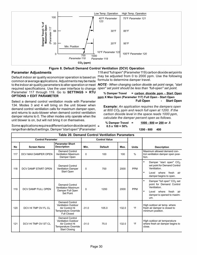
Page 30
33
66
100
700Parameter 118
1000Parameter 119
Low Temp. Operation High Temp. Operation
CO2 (ppm)
10°F Parameter 122
20°F
30°F
40°F Parameter123
105°F Parameter 120
95°F
85°F
75°F Parameter 121
0
Min. PositionDam
per
Tra
vel:
% o
fM
axim
um
Op
en
(Para
mete
r 117
Figure 8. Default Demand Control Ventilation (DCV) Operation
Parameter Adjustments
Default indoor air quality economizer operation is based on
common or average applications. Adjustments may be madeto the indoor air quality parameters to alter operation or meetrequired specifications. Use the user interface to changeParameter 117 through 119. Go to SETTINGS > RTUOPTIONS > EDIT PARAMETER
Select a demand control ventilation mode with Parameter134. Modes 3 and 4 will bring on the unit blower whendemand control ventilation calls for maximum damper open,and returns to auto-blower when demand control ventilationdamper returns to 0. The other modes only operate when the
unit blower is on, but will not bring it on themselves.
Some applications require a different carbon dioxide set pointrange than default settings. Damper “start open" (Parameter
118 and “full open" (Parameter 119) carbon dioxide set pointsmay be adjusted from 0 to 2000 ppm. Use the followingformula to determine damper travel.
NOTE - When changing carbon dioxide set point range, “startopen" set point should be less than “full‐open" set point.
% Damper Travel = carbon dioxide ppm - Start Open
ppm X Max Open (Parameter 117) Full Open - Start Open
Full Open - Start Open
Example: An application requires the dampers openat 800 CO2 ppm and reach full open at 1200. If the
carbon dioxide level in the space reads 1000 ppm,calculate the damper percent open as follows.
% Damper Travel = 1000 - 800 or 200 or .5= 0.5 x 100 = 50%
1200 - 800 400
Table 20. Demand Control Ventilation Parameters
Control Parameter Control Value
Units DescriptionNo Screen Name
Parameter ShortDescription Min. Default Max.
117 DCV MAX DAMPER OPENDemand Control
Ventilation MaximumDamper Open
0 100 100 %Maximum allowed demand control ventilation damper open position.
118 DCV DAMP START OPENDemand Control
Ventilation DamperStart Open
0 700 2000 PPM
� Damper “start open" CO2
set point for Demand ControlVentilation.
� Level where fresh air
damper begins to open.
119 DCV DAMP FULL OPEN
Demand ControlVentilation MaximumDamper Full Open
Set Point
0 1200 2000 PPM
� Damper “full open" CO2 set
point for Demand ControlVentilation.
� Level where fresh air
damper is opened to maximum.
120 DCV HI TMP OV FL CL
Demand ControlVentilation Outdoor
Air Control HiTemperature Override
Full Closed
-31.0 105.0 132.0 °FHigh outdoor air temp. wherefresh air damper is closed tominimum position.
121 DCV HI TMP OV ST CL
Demand ControlVentilation Outdoor
Air Control HiTemperature Override
Start Closing
-31.0 75.0 132.0 °FHigh outdoor air temperaturewhere fresh air damper begins toclose.
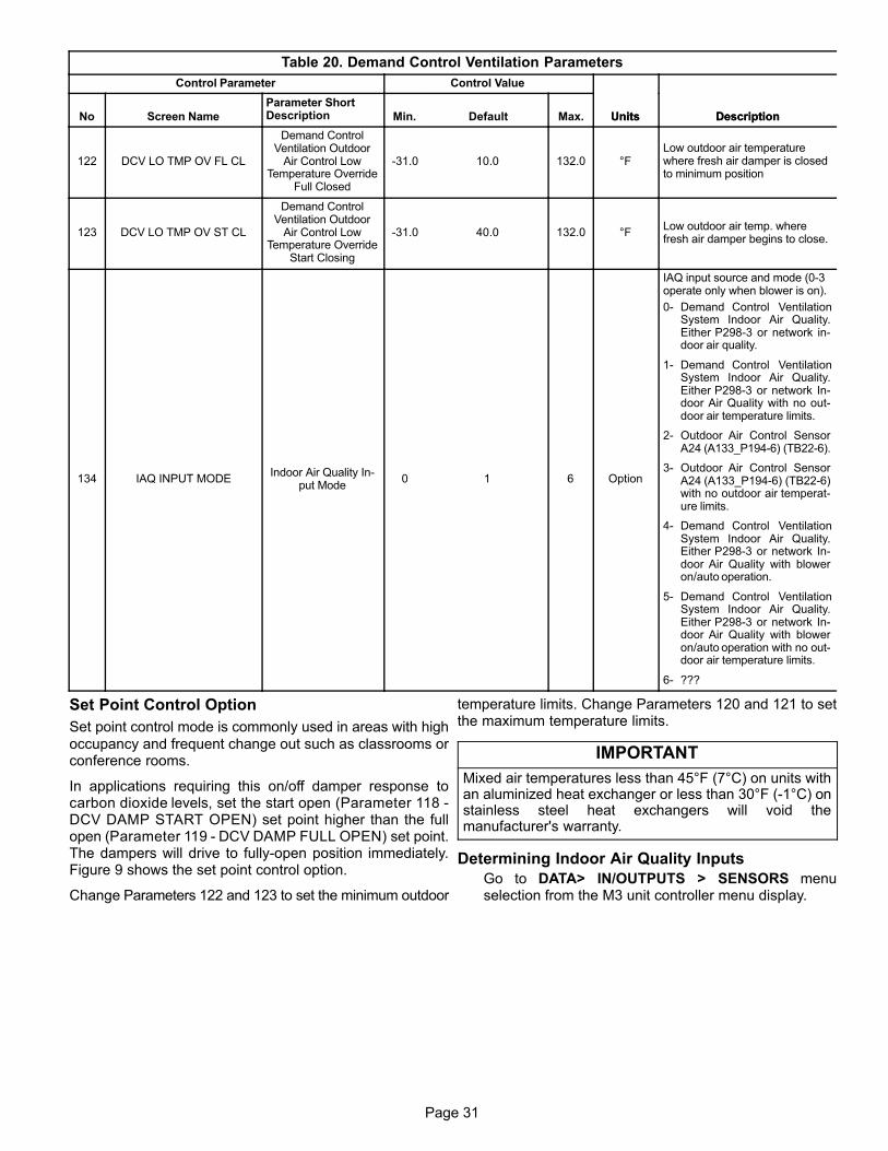
Page 31
Page 31
Table 20. Demand Control Ventilation Parameters
Control Parameter
DescriptionUnits
Control Value
No DescriptionUnitsMax.DefaultMin.
Parameter ShortDescriptionScreen Name
122 DCV LO TMP OV FL CL
Demand ControlVentilation Outdoor
Air Control LowTemperature Override
Full Closed
-31.0 10.0 132.0 °FLow outdoor air temperaturewhere fresh air damper is closedto minimum position
123 DCV LO TMP OV ST CL
Demand ControlVentilation Outdoor
Air Control LowTemperature Override
Start Closing
-31.0 40.0 132.0 °FLow outdoor air temp. wherefresh air damper begins to close.
134 IAQ INPUT MODEIndoor Air Quality In
put Mode0 1 6 Option
IAQ input source and mode (0-3operate only when blower is on).
0- Demand Control VentilationSystem Indoor Air Quality.Either P298-3 or network indoor air quality.
1- Demand Control VentilationSystem Indoor Air Quality.Either P298-3 or network Indoor Air Quality with no outdoor air temperature limits.
2- Outdoor Air Control SensorA24 (A133_P194-6) (TB22-6).
3- Outdoor Air Control SensorA24 (A133_P194-6) (TB22-6)with no outdoor air temperature limits.
4- Demand Control VentilationSystem Indoor Air Quality.Either P298-3 or network Indoor Air Quality with bloweron/auto operation.
5- Demand Control VentilationSystem Indoor Air Quality.Either P298-3 or network Indoor Air Quality with bloweron/auto operation with no outdoor air temperature limits.
6- ???
Set Point Control Option
Set point control mode is commonly used in areas with high
occupancy and frequent change out such as classrooms orconference rooms.
In applications requiring this on/off damper response tocarbon dioxide levels, set the start open (Parameter 118 -DCV DAMP START OPEN) set point higher than the fullopen (Parameter 119 - DCV DAMP FULL OPEN) set point.The dampers will drive to fully-open position immediately.Figure 9 shows the set point control option.
Change Parameters 122 and 123 to set the minimum outdoor
temperature limits. Change Parameters 120 and 121 to setthe maximum temperature limits.
IMPORTANT
Mixed air temperatures less than 45°F (7°C) on units withan aluminized heat exchanger or less than 30°F (-1°C) onstainless steel heat exchangers will void themanufacturer's warranty.
Determining Indoor Air Quality Inputs
Go to DATA> IN/OUTPUTS > SENSORS menuselection from the M3 unit controller menu display.

Page 32
Min. Position
100 Parameter 117
Parameter 119
(full)
Parameter 118
(start)
carbon dioxide (ppm)
Max. Open
Close Open
Figure 9. Set point Control Indoor Air Quality Option
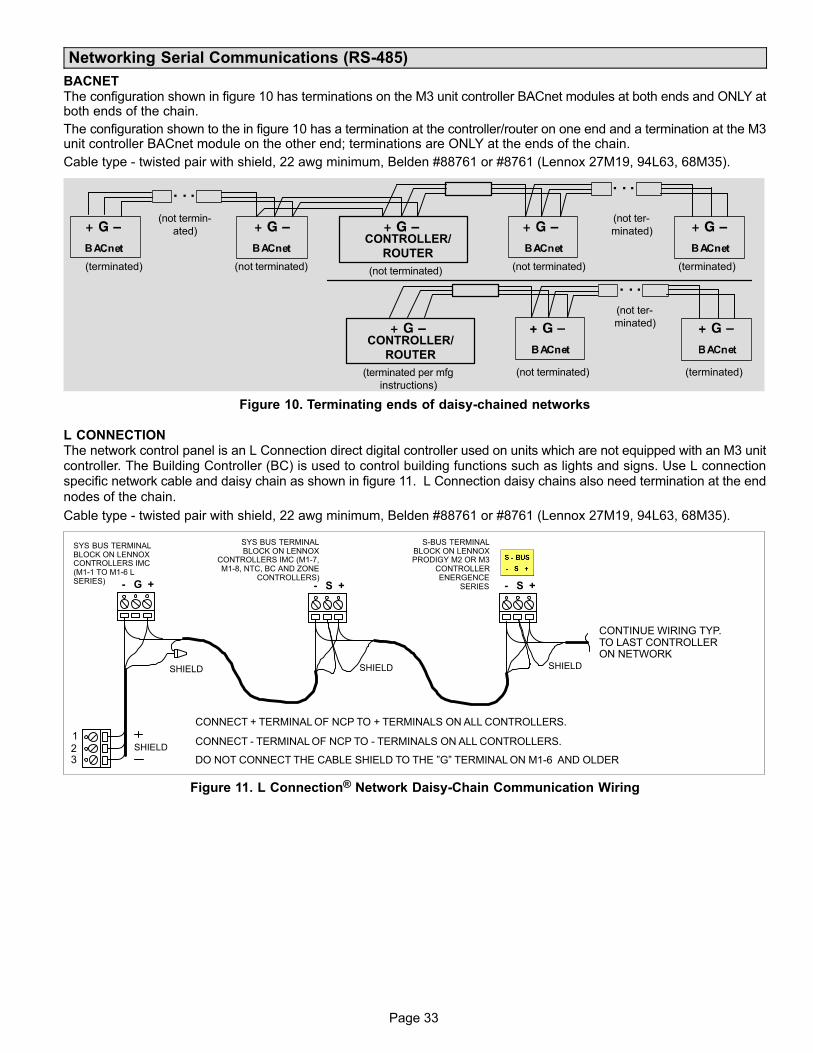
Page 33
Page 33
Networking Serial Communications (RS-485)
BACNETThe configuration shown in figure 10 has terminations on the M3 unit controller BACnet modules at both ends and ONLY atboth ends of the chain.
The configuration shown to the in figure 10 has a termination at the controller/router on one end and a termination at the M3unit controller BACnet module on the other end; terminations are ONLY at the ends of the chain.
Cable type - twisted pair with shield, 22 awg minimum, Belden #88761 or #8761 (Lennox 27M19, 94L63, 68M35).
(terminated)(terminated) (not terminated) (not terminated)
CONTROLLER/
ROUTER
(not ter
minated)
(not termin
ated)
(not terminated)
(terminated per mfg
instructions)
CONTROLLER/
ROUTER
(not terminated) (terminated)
(not ter
minated)
Figure 10. Terminating ends of daisy-chained networks
L CONNECTIONThe network control panel is an L Connection direct digital controller used on units which are not equipped with an M3 unitcontroller. The Building Controller (BC) is used to control building functions such as lights and signs. Use L connectionspecific network cable and daisy chain as shown in figure 11. L Connection daisy chains also need termination at the end
nodes of the chain.
Cable type - twisted pair with shield, 22 awg minimum, Belden #88761 or #8761 (Lennox 27M19, 94L63, 68M35).
SYS BUS TERMINALBLOCK ON LENNOXCONTROLLERS IMC(M1-1 TO M1-6 LSERIES)
S-BUS TERMINALBLOCK ON LENNOXPRODIGY M2 OR M3
CONTROLLERENERGENCE
SERIES
SYS BUS TERMINALBLOCK ON LENNOX
CONTROLLERS IMC (M1-7,M1-8, NTC, BC AND ZONE
CONTROLLERS)
DO NOT CONNECT THE CABLE SHIELD TO THE ”G” TERMINAL ON M1-6 AND OLDER
CONNECT + TERMINAL OF NCP TO + TERMINALS ON ALL CONTROLLERS.
CONNECT - TERMINAL OF NCP TO - TERMINALS ON ALL CONTROLLERS.
321
SHIELD SHIELD SHIELD
- S + - S +- G +
SHIELD
CONTINUE WIRING TYP.TO LAST CONTROLLERON NETWORK
Figure 11. L Connection® Network Daisy-Chain Communication Wiring

Page 34
APPENDIX
AbbreviationsA55 M3 board. Main controller board for roof top units
A178 C3 board. Compressor 3 and 4, 2nd stage heat
AI Analog input
AO Analog output
BL Blower
BRPM Blower RPM
C1 1st stage cooling
C2 2nd stage cooling
C3 3rd stage cooling
C4 4th stage cooling
CAI Combustion air inducer
CAVB Constant air volume with bypass damper
COM Electrical common
CLK Clock
CP1 Compressor 1
CP2 Compressor 2
CP3 Compressor 3
CP4 Compressor 4
CSP Cooling set point
DAC Discharge (supply) air control
DACC Discharge (supply) air control cooling
DACH Discharge (supply) air control heating
DAP Discharge (supply) air pressure
DAT Discharge (supply) air temperature
DB Deadband
DCV Demand controlled ventilation
DDC Direct Digital Controller
DI Digital input
Diff Differential
DO Digital output
ECON Economizer
FAC Fresh air cooling control
FAH Fresh air heating control
FAT Fresh air tempering control. See FAC & FAH
FC Free cooling
G Thermostat demand, blower
GLO Global mode or input (economizer)
H1 1st stage heating
H2 2nd stage heating
H3 3rd stage heating
H4 4th stage heating
HP1 Heat pump add-on board (A61)
HP High pressure
HSP Heating setpoint
HT Heating
IAQ Indoor air quality. Often synonymous with CO2 level in ppm
IDE Indoor enthalpy. Depends on temperature and humidity
IE Indoor enthalpy.
“w.c. Inches of water column
LCONN L Connection
LED Light emitting diode. An indicator light, found either as individualelements or grouped together as segments to form characters
LP Low pressure
LT Limit
M3 Main M3 unit controller board (A55).
MGV Modulating gas valve
MOAD Motorized outdoor air damper
MSAV Multi-Stage Air Volume
OAC Outdoor air control
OAS Outdoor air suitable for free cooling
OAT Outdoor air temperature
OCC Unit controller demand, occupied mode
ODE Outdoor enthalpy. Depends on temperature and humidity
OE Outdoor enthalpy.
PPM Parts per million (mostly used for CO2 measurements)
RAP Return air pressure
RAT Return air temperature
RH Relative humidity
RS Reset
RTU Roof top unit
RT6 Discharge air temperature sensor
RT16 Return air temperature sensor
RT17 Outdoor air temperature sensor
SMK Smoke detection mode (alarm)
SP Set point
Stg Stage
STPT Set point
TB Terminal block
TSTAT Thermostat
UNOCC Unit controller demand, unoccupied mode
USB Universal Serial Bus, connect to PC or flash drive
W1 Thermostat demand, heat stage 1
W2 Thermostat demand, heat stage 2
W3 Thermostat demand, heat stage 3
W4 Thermostat demand, heat stage 4
VAC Alternating current voltage
VAV Variable air volume. Accomplished with a variable frequency drive(VFD)
VDC Direct current voltage
VFD Var. frequency drive. An AC inverter used to vary motor speed
VT Ventilation
Y1 Thermostat demand, cooling stage one
Y2 Thermostat demand, cooling stage two
Y3 Thermostat demand, cooling stage three
Y4 Thermostat demand, cooling stage four
ZAT Room air temperature
Table 21. Parts and Kits Available for M3 Unit Controller
Description
Catalognumber Description
Catalognumber Description
Catalognumber
Unit Controller Replacement kit 10X84 USB service kit tube 59W52 SmartWire� Field Termination kit 59W57
LCD Display Replacement Kit 10X85 M3 unit controller battery (10-pack) 59W53Lennox Prodigy 2.0 USB MemoryStick (5-pack)
59W59
M3 unit controller cover 10X86 BACnet� Replacement kit 59W51

Page 35
Page 35
USB Service Report Example (If SmartAirflow® is Installed)
======================================================USB SERVICE REPORT======================================================Service Date 04:03:2014Service Time 19:26:35Serial No.Software Version 08.00.0009Hardware VersionUnit Number UNIT 1SBUS Address 2BACnet Address 2Catalogue NumberModel Number LGH060H4EH1YCONFIGURATION ID 1 NTNNNNLNCONFIGURATION ID 2 NNNNNNNNNStatus IDLE======================================================Runtime Data Total Power On 23 HRS 8 CYCLES Before Install 0 HRS −−−−−−− Filter 12 HRS −−−−−−− Belt 11 HRS −−−−−−− Blower 12 HRS 50 CYCLES Compressor 1 3 HRS 40 CYCLES Compressor 2 4 HRS 27 CYCLES Compressor 3 0 HRS 2 CYCLES Compressor 4 0 HRS 3 CYCLES Outdoor Fan 1 7 HRS 28 CYCLES Outdoor Fan 2 2 HRS 22 CYCLES Outdoor Fan 3 0 HRS 2 CYCLES Outdoor Fan 4 0 HRS 3 CYCLES Outdoor Fan 5 0 HRS 3 CYCLES Outdoor Fan 6 0 HRS 3 CYCLES POWER EXHAUST 0 HRS 0 CYCLES Heat Stage 1 0 HRS 1 CYCLES Heat Stage 2 0 HRS 1 CYCLES Humiditrol 0 HRS 0 CYCLES Free Cooling 0 HRS 4 CYCLES UV Lamp 0 HRS −−−−−−−======================================================Sensor Data OAT 66 degF RAT 72 degF DAT 73 degF ZAT 78 degF RH 50 % CO2 460 ppm======================================================SmartAirFlow System Data
Calibrated On 04/03/2014 19:12:56
Supply Airflow Calibration Table −−−−−−−−−−−−−−−−−−−−−−−−−−−−−−−−−−−−−− PWM(%) Speed(rpm) Airflow(cfm) −−−−−−−−−−−−−−−−−−−−−−−−−−−−−−−−−−−−−− 20 480 1031 30 570 1274 40 660 1493 50 750 1687 60 840 1857 70 930 2004 80 1020 2126 90 1110 2223 100 1200 2297
Supply Airflow Targets −−−−−−−−−−−−−−−−−−−−−−−−−−−−−−−−−−−−−−−−−−−−−−−− Mode Desired Airflow(cfm) PWM(%)
−−−−−−−−−−−−−−−−−−−−−−−−−−−−−−−−−−−−−−−−−−−−−−−− Cool High 1800 57 Cool Low 1300 31 Heat 2000 70 Ventilation 1200 27 Smoke 2000 70Economizer Differential Pressure(@ 2000 SupplyAirflow(cfm)) −−−−−−−−−−−−−−−−−−−−−−−−−−−−−−−−−−−−−−−−−−−−−−−− Damper Position (%) Diff.Pressure(in.H20) −−−−−−−−−−−−−−−−−−−−−−−−−−−−−−−−−−−−−−−−−−−−−−−− 0 0.39 50 0.23 100 0.06 Outside Airflow Targets −−−−−−−−−−−−−−−−−−−−−−−−−−−−−−−−−−−−−−−−−−−− Minimum Outside Air/Minimum DCV: 200 cfm Maximum DCV: 0 cfm Minimum CO2: 700 ppm Maximum CO2: 1200 ppm======================================================Alarm/Status Log (143) 04:03:2014 19:26:13 RESET DAMPER PRESSURE (141) 04:03:2014 19:26:13 RESET CFM TARGET TOOHIGH (143) 04:03:2014 19:06:19 SET DAMPER PRESSURE (141) 04:03:2014 19:06:19 SET CFM TARGET TOOHIGH ( 82) 04:03:2014 19:06:18 RESET CONTROLLER RESET ( 82) 04:03:2014 19:06:18 SET CONTROLLER RESET (143) 04:03:2014 18:59:41 SET DAMPER PRESSURE (141) 04:03:2014 18:59:41 SET CFM TARGET TOOHIGH ( 82) 04:03:2014 18:59:40 RESET CONTROLLER RESET ( 82) 04:03:2014 18:59:40 SET CONTROLLER RESET (143) 04:03:2014 18:35:19 SET DAMPER PRESSURE (141) 04:03:2014 18:35:19 SET CFM TARGET TOOHIGH (148) 04:03:2014 18:21:36 RESET SMART AIRFLOWCONFIG ERROR (170) 04:03:2014 18:21:36 RESET POWER EXHAUSTUNCONFIGURED (165) 04:03:2014 18:21:36 RESET ECONOMIZERUNCONFIGURED ( 85) 04:03:2014 18:21:36 RESET INCORRECTHUMIDITROL SETTINGS (132) 04:03:2014 18:21:24 RESET VFD BYPASSUNCONFIGURED (148) 04:03:2014 18:21:23 SET SMART AIRFLOWCONFIG ERROR (132) 04:03:2014 18:21:23 SET VFD BYPASSUNCONFIGURED (170) 04:03:2014 18:21:23 SET POWER EXHAUSTUNCONFIGURED (165) 04:03:2014 18:21:23 SET ECONOMIZERUNCONFIGURED ( 85) 04:03:2014 18:21:23 SET INCORRECTHUMIDITROL SETTINGS ( 82) 04:03:2014 18:20:31 RESET CONTROLLER RESET ( 82) 04:03:2014 18:20:31 SET CONTROLLER RESET ( 82) 04:03:2014 18:16:32 RESET CONTROLLER RESET ( 82) 04:03:2014 18:16:32 SET CONTROLLER RESET ( 82) 04:03:2014 18:14:10 RESET CONTROLLER RESET ( 82) 04:03:2014 18:14:10 SET CONTROLLER RESET ( 82) 04:03:2014 18:14:09 RESET CONTROLLER RESET ( 82) 04:03:2014 18:14:09 SET CONTROLLER RESET
======================================================END OF REPORT

Page 36
USB Service Report Example (If SmartAirflow® is Installed)
======================================================
USB SMARTAIRFLOW REPORT
======================================================
Service Date 04:03:2014
Service Time 19:32:49
Serial No.
Software Version 08.00.0009
Hardware Version
Unit Number UNIT 1
SBUS Address 2
BACnet Address 2
Catalogue Number
Model Number LGH060H4EH1Y
CONFIGURATION ID 1 NTNNNNLN
CONFIGURATION ID 2 NNNNNNNNN
Status IDLE
======================================================
Calibrated On 04/03/2014 19:12:56
Supply Airflow Calibration Table
--------------------------------------
PWM(%) Speed(rpm) Airflow(cfm)
--------------------------------------
20 480 1031
30 570 1274
40 660 1493
50 750 1687
60 840 1857
70 930 2004
80 1020 2126
90 1110 2223
100 1200 2297
Supply Airflow Set Points
------------------------------------------------------
Desired Actual
Airflow(cfm)
Mode Airflow(cfm) PWM(%) (With Damper
Closed) Econ dP
------------------------------------------------------
Cool Low 1300 31 1687
0.21
Cool High 1800 57 1297
0.13
Heat 2000 70 1809
0.25
Ventilation 1200 27 2004
0.30
Smoke 2000 70 1204
0.11
Outside Airflow Targets
--------------------------------------------
Minimum Outside Air/Minimum DCV: 200 cfm
Maximum DCV: 0 cfm
Minimum CO2: 700 ppm
Maximum CO2: 1200 ppm
Ventilation Calibration(@ 2000 Supply
Airflow(cfm))
------------------------------------------------------
Damper Outdoor Supply
Supply
Position(%) Econ dP Airflow(cfm) PWM(%)
Airflow(cfm)
------------------------------------------------------
0% 0.30 0 70
2004
5% 0.29 104 70
2004
10% 0.28 184 70
2004
15% 0.27 261 70
2004
20% 0.26 325 70
2004
25% 0.24 437 70
2004
30% 0.23 561 70
2004
======================================================
END OF REPORT

Page 37
Page 37
Pro
dig
y 2
.0 —
Ala
rms
Ph
as
e -
Vo
lta
ge
De
tec
tio
nT
he
M3 u
nit c
ontr
olle
r has the a
bili
ty to d
ete
ct th
at th
e r
ooftop u
nit p
ow
er
sourc
e h
as the c
orr
ect fr
equency,
phasin
g a
nd v
oltage levels
. W
hen this
featu
re is e
nable
d,
the d
ete
ction o
f fr
equency a
nd p
hasin
g is d
ete
rmin
ed a
t pow
er-
on a
nd the v
oltage level is
continuously
monitore
d. If a
ny o
f th
ese is o
ut of ra
nge, th
en a
n a
larm
is
logged a
nd the r
ooftop u
nit o
pera
tion is locked o
ut.
1.
Ala
rms D
ete
cte
d a
t P
ow
er-
On
Sta
rt u
p:
�121 -
LIN
E F
RE
Q D
OE
S N
OT
MA
TC
H U
NIT
CO
NF
IG
�126 -
LIN
E P
HA
SIN
G D
OE
S N
OT
MA
TC
H U
NIT
CO
NF
IG
2.
Ala
rms -
Co
nti
nu
ou
sly
Mo
nit
ori
ng
�122 -
24V
AC
PR
MA
RY
VO
LTA
GE
LO
W
�123 -
24V
AC
PR
IMA
RY
VO
LTA
GE
HIG
H
�134 -
24V
AC
SE
CO
ND
AR
Y V
OLTA
GE
LO
W
�125 -
24V
AC
SE
CO
ND
AR
Y V
OLTA
GE
HIG
H
Ala
rms 1
22 thro
ugh 1
25 a
re a
uto
-resettin
g. T
he r
ooftop o
pera
tion w
ill b
e r
esto
red fiv
e (
5)
min
ute
s a
fter
the p
roper
voltage levels
are
resto
red. A
larm
s 1
21 a
nd 1
26
requires r
em
ovin
g the p
ow
er
and c
orr
ecting the issue b
efo
re r
esto
ring the r
ooftop o
pera
tion
The
fre
quency (
60 o
r 50 H
z)
and the p
hasin
g (
sin
gle
or
thre
e-p
hase)
of th
e p
ow
er
sourc
e is d
ete
rmin
ed b
y the m
odel num
ber
sto
red in the M
3 u
nit c
ontr
olle
r. T
his
model num
ber
and e
nablin
g/d
isablin
g the P
hase-V
oltage D
ete
ction featu
re c
an b
e m
odifie
d thro
ugh the M
3 u
nit c
ontr
olle
r user
inte
rface. S
ee the Insta
llation a
nd
Setu
p G
uid
e for
instr
uctions o
n h
ow
to c
onfigure
the C
ON
FIG
UR
AT
ION
ID
2, P
ositio
n 5
. O
ptions a
re:
N =
NO
T IN
STA
LLE
D
1 =
EN
AB
LE
D IN
TE
RN
AL (
LE
NN
OX
)
2 =
EX
TE
RN
AL (
A42)
PH
AS
E D
ET
EC
TIO
N O
N D
I-2
3 =
EX
TE
RN
AL (
A42)
PH
AS
E D
ET
EC
TIO
N O
N D
I-3
When a
n e
vent occurs
, th
e M
3 u
nit c
ontr
olle
r w
ill d
ispla
y a
code w
hic
h c
orr
esponds to c
ontr
ol fu
nction. E
rror
codes a
re s
tore
d a
nd c
an b
e r
ecalle
d late
r. S
ee the
Insta
llation &
Setu
p G
uid
e F
or
The P
rodig
y M
3 u
nit c
ontr
olle
r fo
r in
form
ation a
bout vie
win
g a
nd s
ilencin
g the a
larm
s v
ia the u
ser
inte
rface.
NO
TE
- A
ny r
efe
ren
ces in
th
e u
ser
inte
rface r
efe
ren
cin
g A
dvan
ced
Air
flo
w a
ctu
ally in
dic
ate
s S
mart
Air
flo
w®.
Se
rvic
e R
ela
ys
Sele
cte
d a
larm
s (
mark
ed w
ith *
in t
able
re
sult in t
he c
losure
of
the s
erv
ice r
ela
y c
onta
cts
(D
O1).
The c
onta
cts
rem
ain
clo
sed u
ntil th
e P
rodig
y r
esets
, or
ala
rm
conditio
n is c
leare
d A
ND
ala
rm s
tatu
s is r
ead v
ia e
xplic
it S
BU
S c
om
mand.
Oth
er
modes o
f opera
tion m
ay b
e s
ele
cte
d a
nd a
re d
escribed in the P
rodig
y A
pplic
ation
Guid
e (
Advanced F
eatu
res).

Page 38
NO
TE
- A
ny r
efe
ren
ces in
th
e u
ser
inte
rface r
efe
ren
cin
g A
dvan
ce A
irfl
ow
actu
ally in
dic
ate
s S
mart
Air
flo
w®.
AL
AR
MC
OD
ES
TA
BL
E 2
2. P
RO
DIG
Y 2
.0 A
LA
RM
AN
D E
VE
NT
CO
DE
S
Sele
cte
d a
larm
s (
mark
ed w
ith *
in table
result in the c
losure
of th
e s
erv
ice r
ela
y c
onta
cts
(D
O1).
DIS
PL
AY
ME
SS
AG
EE
ven
t A
cti
on
1LO
SS
OF
PO
WE
R D
ET
EC
TIO
N (
SIN
GLE
PH
AS
E U
NIT
S)
Check p
ow
er
connections.
The u
nit c
ontr
olle
r w
ill s
et an a
larm
Err
atic P
ow
er
whenever
serv
ice is turn
ed o
ff d
ue to d
ete
ction o
f pow
er
loss. U
ser
will
be a
ble
to c
lear
Err
atic P
ow
er
ala
rm v
ia U
ser
Inte
rface. T
he u
nit c
ontr
olle
r w
ill c
lear
Pow
er
Err
atic a
fter
the C
om
pre
ssor
Min
OF
F D
ela
yhas e
xpired. If c
om
pre
ssor
dem
and is s
till
pre
sent th
e u
nit c
ontr
olle
r w
ill r
esta
rt c
om
pre
ssors
after
the C
om
pre
ssor
Min
OF
F D
ela
yhas e
xpired.
2 -
3 R
ES
ER
VE
D
4*
SM
OK
E D
ET
EC
TO
R IN
PU
T (
A173)
A173 input is
sensed a
s c
losed. w
ill a
uto
matically
cle
ars
once input is
dete
cte
d o
pen. S
moke m
ode, check for
sourc
e o
f sm
oke.
While
Sm
oke A
larm
is a
ctive, th
e u
nit c
ontr
olle
r w
ill n
ot serv
ice a
ny c
oolin
g, heating o
r ventila
tion d
em
and.
5*
BLO
WE
R S
52
Unit o
ff. A
ir flo
w s
witch is n
orm
ally
clo
sed. M
onitoring s
tart
s 1
6 S
econds a
fter
blo
wer
is s
tart
ed. if a
ir flo
w s
witch is d
ete
cte
d o
pen
after
16 s
econd d
ela
y p
eriod, all
com
pre
ssors
are
de-e
nerg
ized, gas v
alv
es c
losed, ele
ctr
ic h
eat tu
rned o
ff, econom
izer
dam
per
clo
sed, and b
low
er
is s
topped. ala
rm w
ill a
uto
matically
cle
ar
once the e
rror
tim
ed o
ff d
ela
y h
as e
xpired a
nd s
yste
m w
ill r
esum
e.
Check b
low
er
opera
tion.
6*
DIR
TY
FIL
TE
R S
WIT
CH
S27
Dirty
filt
er
sw
itch is d
ete
cte
d a
s c
losed. w
ill a
uto
matically
cle
ar
once s
witch is d
ete
cte
d o
pen. R
epla
ce filt
er
or
check filt
er
sw
itch
S27 .
7R
ES
ER
VE
D
8*
ST
RIK
E 3
ON
BLO
WE
R S
52
Lockout, m
ultip
le a
larm
code 5
dete
cte
d. ala
rm c
an b
e m
anually
cle
are
d v
ia the u
ser
inte
rface. C
heck b
low
er
opera
tion. once p
rob
lem
is c
orr
ecte
d, lo
ckout ala
rm c
an b
e c
leare
d b
y r
esettin
g the u
nit c
ontr
olle
r.
9 -
11 R
ES
ER
VE
D
12
CO
MP
1 H
IGH
PR
ES
S S
4 O
R H
I T
EM
P S
5
Com
pre
ssor
is o
ff. C
heck c
harg
e, fa
ns a
nd c
oil.
NO
TE
: O
n U
ltra
Hig
h E
ffic
iency u
nits -
if o
nly
ala
rm 1
2 is p
resent th
en issue c
ould
be h
igh tem
pera
ture
S5. IF
ala
rm 1
2 is a
ccom
panie
d w
ith a
larm
14 then m
ost lik
ely
hig
h p
ressure
S4.
The u
nit c
ontr
olle
r w
ill c
lear
Hig
h p
ressure
Sw
itch a
larm
when c
orr
espondin
g H
igh P
ressure
Sw
itch is d
ete
cte
d a
s c
losed. C
om
pre
ssor
will
not be r
esta
rted u
ntil corr
espondin
g H
igh P
ressure
Sw
itch is c
losed a
nd M
inim
um
Off D
ela
y (
Coolin
g o
r H
eating)
has
expired.
13*
ST
RIK
E 3
ON
CO
MP
1 H
IGH
PR
ES
S S
4 O
R H
IT
EM
P S
5
Com
pre
ssor
lockout. C
heck c
harg
e, fa
ns a
nd c
oil.
Use s
erv
ice m
enu to c
lear
lockouts
.
User
will
be a
ble
to c
lear
hig
h p
ressure
sw
itch c
om
pre
ssor
lockout and a
larm
via
user
inte
rface. H
igh p
ressure
sw
itch c
om
pre
ssor
lockout and a
larm
will
be c
leare
d a
fter
the M
3 u
nit c
ontr
olle
r re
set.
Hig
h p
ressure
sw
itch c
om
pre
ssor
lockout and a
larm
will
be c
leare
d o
n term
ination o
f coolin
g d
em
and.
Defa
ult is 3
occurr
ences a
nd c
an b
e s
et betw
een 1
and 7
occurr
ences.
14
CO
MP
2 H
IGH
PR
ES
S S
7
Com
pre
ss is o
ff. C
heck c
harg
e, fa
ns a
nd c
oil.
Note
: O
n U
ltra
Hig
h E
ffic
iency U
nits tandem
ala
rms (
14)
Com
pre
ssor
2 H
igh T
em
pera
ture
S8. If a
ccom
panie
d w
ith a
larm
15 then
most lik
ely
the S
4 H
igh P
ressure
Sw
itch
The u
nit c
ontr
olle
r w
ill c
lear
Hig
h p
ressure
Sw
itch a
larm
when c
orr
espondin
g H
igh P
ressure
Sw
itch is d
ete
cte
d a
s c
losed. C
om
pre
ssor
will
not be r
esta
rted u
ntil corr
espondin
g H
igh P
ressure
Sw
itch is c
losed a
nd M
inim
um
Off D
ela
y (
Coolin
g o
r H
eating)
has
expired.
15*
ST
RIK
E 3
ON
CO
MP
2 H
IGH
PR
ES
S S
5 O
R S
7
Com
pre
ssor
lockout. C
heck c
harg
e, fa
ns a
nd c
oil.
Use s
erv
ice m
enu to c
lear
lockouts
.
User
will
be a
ble
to c
lear
hig
h p
ressure
sw
itch c
om
pre
ssor
lockout and a
larm
via
user
inte
rface. H
igh p
ressure
sw
itch c
om
pre
ssor
lockout and a
larm
will
be c
leare
d a
fter
the M
3 u
nit c
ontr
olle
r re
set.
Hig
h p
ressure
sw
itch c
om
pre
ssor
lockout and a
larm
will
be c
leare
d o
n r
em
oval of coolin
g d
em
and.
Defa
ult is 3
occurr
ences a
nd c
an b
e s
et betw
een 1
and 7
occurr
ences.

Page 39
Page 39
TA
BL
E 2
2. P
RO
DIG
Y 2
.0 A
LA
RM
AN
D E
VE
NT
CO
DE
S
Sele
cte
d a
larm
s (
mark
ed w
ith *
in table
result in the c
losure
of th
e s
erv
ice r
ela
y c
onta
cts
(D
O1).
A
LA
RM
CO
DE
S
Even
t A
cti
on
DIS
PL
AY
ME
SS
AG
E
AL
AR
MC
OD
ES
16
CO
MP
3 H
IGH
PR
ES
S S
28
Com
pre
ssor
is o
ff. C
heck c
harg
e, fa
ns a
nd c
oil.
The u
nit c
ontr
olle
r w
ill c
lear
Hig
h p
ressure
Sw
itch a
larm
when c
orr
espondin
g H
igh P
ressure
Sw
itch is d
ete
cte
d a
s c
losed. C
om
pre
ssor
will
not be r
esta
rted u
ntil corr
espondin
g H
igh P
ressure
Sw
itch is c
losed a
nd M
inim
um
Off D
ela
y (
Coolin
g o
r H
eating)
has
expired.
17*
ST
RIK
E 3
ON
CO
MP
3 H
IGH
PR
ES
S S
28
Com
pre
ssor
lockout. C
heck c
harg
e, fa
ns a
nd c
oil.
Use s
erv
ice m
enu to c
lear
lockouts
.
User
will
be a
ble
to c
lear
hig
h p
ressure
sw
itch c
om
pre
ssor
lockout and a
larm
via
user
inte
rface. H
igh p
ressure
sw
itch c
om
pre
ssor
lockout and ala
rm w
ill b
e c
leare
d a
fter
the M
3 u
nit c
ontr
olle
r re
set.
Hig
h p
ressure
sw
itch c
om
pre
ssor
lockout and a
larm
is c
leare
d o
n r
em
oval of coolin
g d
em
and. D
efa
ult is 3
occurr
ences a
nd c
an b
eset betw
een 1
and 7
occurr
ences.
18
CO
MP
4 H
IGH
PR
ES
S S
96
Com
pre
ssor
lockout. C
heck c
harg
e, fa
ns a
nd c
oil.
The u
nit c
ontr
olle
r w
ill c
lear
Hig
h p
ressure
Sw
itch a
larm
when c
orr
espondin
g H
igh P
ressure
Sw
itch is d
ete
cte
d a
s c
losed. C
om
pre
ssor
will
not be r
esta
rted u
ntil corr
espondin
g H
igh P
ressure
Sw
itch is c
losed a
nd M
inim
um
Off D
ela
y (
Coolin
g o
r H
eating)
has
expired.
19*
ST
RIK
E 3
ON
CO
MP
4 H
IGH
PR
ES
S S
96
Com
pre
ssor
lockout. C
heck c
harg
e, fa
ns a
nd c
oil.
Use s
erv
ice m
enu to c
lear
lockouts
.
User
will
be a
ble
to c
lear
hig
h p
ressure
sw
itch c
om
pre
ssor
lockout and a
larm
via
user
inte
rface. H
igh p
ressure
sw
itch c
om
pre
ssor
lockout and ala
rm w
ill b
e c
leare
d a
fter
the M
3 u
nit c
ontr
olle
r re
set.
Hig
h p
ressure
sw
itch c
om
pre
ssor
lockout and a
larm
is c
leare
d o
n r
em
oval of coolin
g d
em
and. D
efa
ult is 3
occurr
ences a
nd c
an b
eset betw
een 1
and 7
occurr
ences.
NO
TE
E
VE
NT
S 1
21
9 C
OU
LD
ALS
O B
E C
AU
SE
D B
Y A
HIG
H T
EM
PE
RA
TU
RE
CO
ND
ITIO
N O
N S
OM
E C
OM
PR
ES
SO
RS
EQ
UIP
PE
D W
ITH
A H
IGH
TE
MP
ER
AT
UR
E S
HU
TD
OW
N.
20
RE
SE
RV
ED
21
RE
SE
RV
ED
22
CO
MP
1 L
OW
PR
ES
S S
87
Com
pre
ssor
is o
ff. C
heck c
harg
e, fa
ns a
nd c
oil.
U
se s
erv
ice m
enu to c
lear
lockouts
.
23*
ST
RIK
E 3
ON
CO
MP
1 S
87
Com
pre
ssor
is o
ff. C
heck c
harg
e, fa
ns a
nd c
oil.
U
se s
erv
ice m
enu to c
lear
lockouts
.
Num
ber
of occurr
ences is s
et usin
g p
ara
mete
r 99 (
MA
X L
O O
CC
UR
RE
NC
ES
). D
efa
ult is 3
occurr
ences.
24
CO
MP
2 L
OW
PR
ES
S S
88
Com
pre
ssor
is o
ff. C
heck c
harg
e, fa
ns a
nd c
oil.
25*
ST
RIK
E 3
ON
CO
MP
2 S
88
Com
pre
ssor
is o
ff. C
heck c
harg
e, fa
ns a
nd c
oil.
U
se s
erv
ice m
enu to c
lear
lockouts
.
Num
ber
of occurr
ences is s
et usin
g p
ara
mete
r 99 (
MA
X L
O O
CC
UR
RE
NC
ES
). D
efa
ult is 3
occurr
ences.
26
CO
MP
3 L
OW
PR
ES
S S
98
Com
pre
ssor
if o
ff. C
heck c
harg
e, fa
ns a
nd c
oil.
27*
ST
RIK
E 3
ON
CO
MP
3 S
98
Com
pre
ssor
is o
ff. C
heck c
harg
e, fa
ns a
nd c
oil.
U
se s
erv
ice m
enu to c
lear
lockouts
.
Num
ber
of occurr
ences is s
et usin
g p
ara
mete
r 99 (
MA
X L
O O
CC
UR
RE
NC
ES
). D
efa
ult is 3
occurr
ences.
28
CO
MP
4 L
OW
PR
ES
S S
97
Com
pre
ssor
if o
ff. C
heck c
harg
e, fa
ns a
nd c
oil.
29*
ST
RIK
E 3
ON
CO
MP
4 S
97
Com
pre
ssor
is o
ff. C
heck c
harg
e, fa
ns a
nd c
oil.
U
se s
erv
ice m
enu to c
lear
lockouts
.
Num
ber
of occurr
ences is s
et usin
g p
ara
mete
r 99 (
MA
X L
O O
CC
UR
RE
NC
ES
). D
efa
ult is 3
occurr
ences.
30*
DR
AIN
PLA
N O
VE
RLF
OW
SH
UT
DO
WN
(S
149)
Check for
blo
ck d
rain
, condensate
lin
es a
nd d
rain
pan o
verf
low
sw
itch.
Ala
rm s
et if o
verf
low
sw
itch is d
ete
cte
d o
pened a
nd c
om
pre
ssor
will
be locked o
ut. s
yste
m w
ill a
uto
matically
cle
ar
ala
rm o
nce
sw
itch is d
ete
cte
d c
losed. S
yste
m w
ill r
esum
e o
pera
tion (
com
pre
ssor
lockout)
, after
the E
rror
Tim
ed O
FF
Dela
y h
as e
xpired follo
w
ing the O
verf
low
sw
itch a
larm
cle
ar.
31
RE
SE
RV
ED
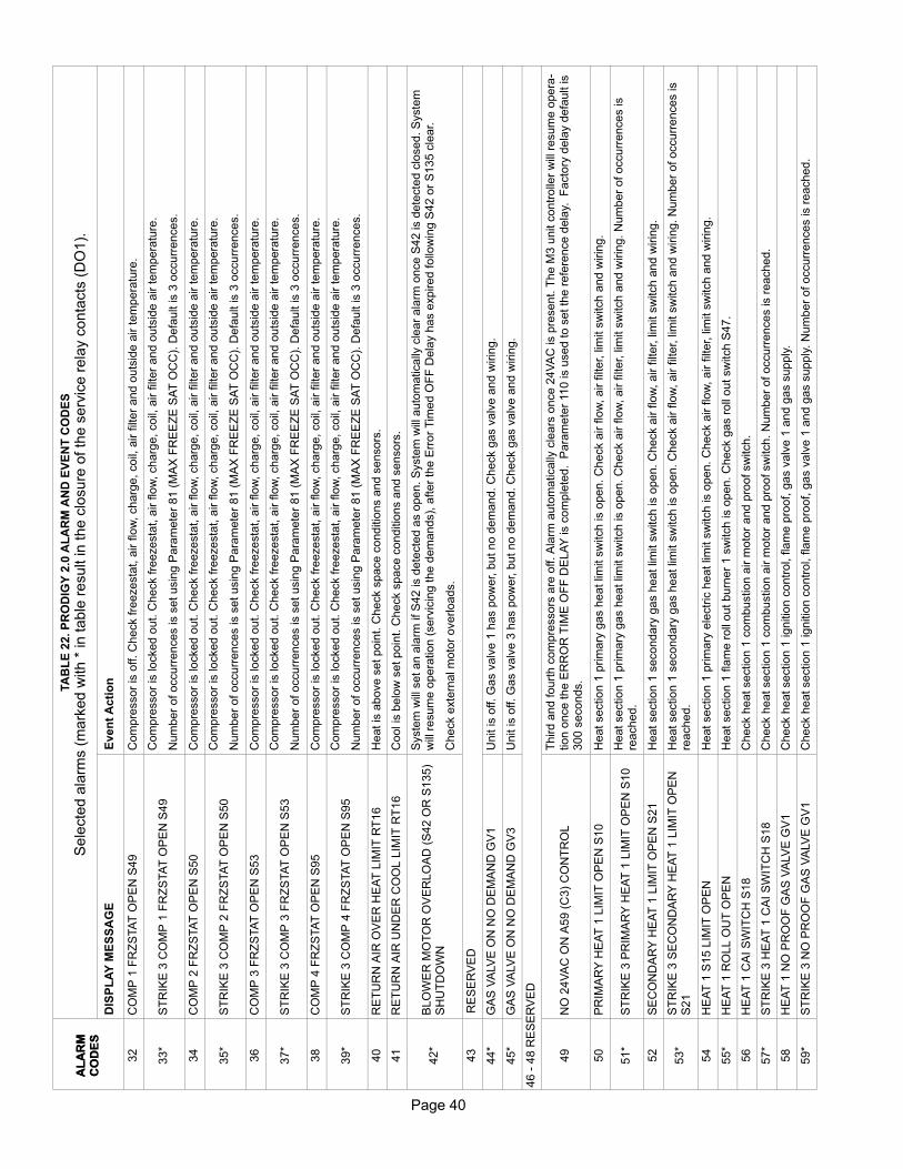
Page 40
TA
BL
E 2
2. P
RO
DIG
Y 2
.0 A
LA
RM
AN
D E
VE
NT
CO
DE
S
Sele
cte
d a
larm
s (
mark
ed w
ith *
in table
result in the c
losure
of th
e s
erv
ice r
ela
y c
onta
cts
(D
O1).
A
LA
RM
CO
DE
S
Even
t A
cti
on
DIS
PL
AY
ME
SS
AG
E
AL
AR
MC
OD
ES
32
CO
MP
1 F
RZ
STA
T O
PE
N S
49
Com
pre
ssor
is o
ff. C
heck fre
ezesta
t, a
ir flo
w, charg
e, coil,
air filt
er
and o
uts
ide a
ir tem
pera
ture
.
33*
ST
RIK
E 3
CO
MP
1 F
RZ
STA
T O
PE
N S
49
Com
pre
ssor
is locked o
ut. C
heck fre
ezesta
t, a
ir flo
w, charg
e, coil,
air filt
er
and o
uts
ide a
ir tem
pera
ture
.
Num
ber
of occurr
ences is s
et usin
g P
ara
mete
r 81 (
MA
X F
RE
EZ
E S
AT
OC
C).
Defa
ult is 3
occurr
ences.
34
CO
MP
2 F
RZ
STA
T O
PE
N S
50
Com
pre
ssor
is locked o
ut. C
heck fre
ezesta
t, a
ir flo
w, charg
e, coil,
air filt
er
and o
uts
ide a
ir tem
pera
ture
.
35*
ST
RIK
E 3
CO
MP
2 F
RZ
STA
T O
PE
N S
50
Com
pre
ssor
is locked o
ut. C
heck fre
ezesta
t, a
ir flo
w, charg
e, coil,
air filt
er
and o
uts
ide a
ir tem
pera
ture
.
Num
ber
of occurr
ences is s
et usin
g P
ara
mete
r 81 (
MA
X F
RE
EZ
E S
AT
OC
C).
Defa
ult is 3
occurr
ences.
36
CO
MP
3 F
RZ
STA
T O
PE
N S
53
Com
pre
ssor
is locked o
ut. C
heck fre
ezesta
t, a
ir flo
w, charg
e, coil,
air filt
er
and o
uts
ide a
ir tem
pera
ture
.
37*
ST
RIK
E 3
CO
MP
3 F
RZ
STA
T O
PE
N S
53
Com
pre
ssor
is locked o
ut. C
heck fre
ezesta
t, a
ir flo
w, charg
e, coil,
air filt
er
and o
uts
ide a
ir tem
pera
ture
.
Num
ber
of occurr
ences is s
et usin
g P
ara
mete
r 81 (
MA
X F
RE
EZ
E S
AT
OC
C).
Defa
ult is 3
occurr
ences.
38
CO
MP
4 F
RZ
STA
T O
PE
N S
95
Com
pre
ssor
is locked o
ut. C
heck fre
ezesta
t, a
ir flo
w, charg
e, coil,
air filt
er
and o
uts
ide a
ir tem
pera
ture
.
39*
ST
RIK
E 3
CO
MP
4 F
RZ
STA
T O
PE
N S
95
Com
pre
ssor
is locked o
ut. C
heck fre
ezesta
t, a
ir flo
w, charg
e, coil,
air filt
er
and o
uts
ide a
ir tem
pera
ture
.
Num
ber
of occurr
ences is s
et usin
g P
ara
mete
r 81 (
MA
X F
RE
EZ
E S
AT
OC
C).
Defa
ult is 3
occurr
ences.
40
RE
TU
RN
AIR
OV
ER
HE
AT
LIM
IT R
T16
Heat is
above s
et poin
t. C
heck s
pace c
onditio
ns a
nd s
ensors
.
41
RE
TU
RN
AIR
UN
DE
R C
OO
L L
IMIT
RT
16
Cool is
belo
w s
et poin
t. C
heck s
pace c
onditio
ns a
nd s
ensors
.
42*
BLO
WE
R M
OT
OR
OV
ER
LO
AD
(S
42 O
R S
135)
SH
UT
DO
WN
Syste
m w
ill s
et an a
larm
if S
42 is d
ete
cte
d a
s o
pen. S
yste
m w
ill a
uto
matically
cle
ar
ala
rm o
nce S
42 is d
ete
cte
d c
losed. S
yste
mw
ill r
esum
e o
pera
tion (
serv
icin
g the d
em
ands),
after
the E
rror
Tim
ed O
FF
Dela
y h
as e
xpired follo
win
g S
42 o
r S
135 c
lear.
Check e
xte
rnal m
oto
r overloads.
43
RE
SE
RV
ED
44*
GA
S V
ALV
E O
N N
O D
EM
AN
D G
V1
Unit is o
ff. G
as v
alv
e 1
has p
ow
er, b
ut no d
em
and. C
heck g
as v
alv
e a
nd w
irin
g.
45*
GA
S V
ALV
E O
N N
O D
EM
AN
D G
V3
Unit is o
ff. G
as v
alv
e 3
has p
ow
er, b
ut no d
em
and. C
heck g
as v
alv
e a
nd w
irin
g.
46 -
48 R
ES
ER
VE
D
49
NO
24V
AC
ON
A59 (
C3)
CO
NT
RO
L
Third a
nd fourt
h c
om
pre
ssors
are
off. A
larm
auto
matically
cle
ars
once 2
4V
AC
is p
resent. T
he M
3 u
nit c
ontr
olle
r w
ill r
esum
e o
pera
tion o
nce the E
RR
OR
TIM
E O
FF
DE
LA
Y is c
om
ple
ted. P
ara
mete
r 110 is u
sed to s
et th
e r
efe
rence d
ela
y. F
acto
ry d
ela
y d
efa
ult is
300 s
econds.
50
PR
IMA
RY
HE
AT
1 L
IMIT
OP
EN
S10
Heat section 1
prim
ary
gas h
eat lim
it s
witch is o
pen. C
heck a
ir flo
w, air filt
er, lim
it s
witch a
nd w
irin
g.
51*
ST
RIK
E 3
PR
IMA
RY
HE
AT
1 L
IMIT
OP
EN
S10
Heat section 1
prim
ary
gas h
eat lim
it s
witch is o
pen. C
heck a
ir flo
w, air filt
er, lim
it s
witch a
nd w
irin
g. N
um
ber
of occurr
ence
s is
reached.
52
SE
CO
ND
AR
Y H
EA
T 1
LIM
IT O
PE
N S
21
Heat section 1
secondary
gas h
eat lim
it s
witch is o
pen. C
heck a
ir flo
w, air filt
er, lim
it s
witch a
nd w
irin
g.
53*
ST
RIK
E 3
SE
CO
ND
AR
Y H
EA
T 1
LIM
IT O
PE
NS
21
Heat section 1
secondary
gas h
eat lim
it s
witch is o
pen. C
heck a
ir flo
w, air filt
er, lim
it s
witch a
nd w
irin
g. N
um
ber
of occurr
ences is
reached.
54
HE
AT
1 S
15 L
IMIT
OP
EN
Heat section 1
prim
ary
ele
ctr
ic h
eat lim
it s
witch is o
pen. C
heck a
ir flo
w, air filt
er, lim
it s
witch a
nd w
irin
g.
55*
HE
AT
1 R
OLL O
UT
OP
EN
Heat section 1
fla
me r
oll
out burn
er
1 s
witch is o
pen. C
heck g
as r
oll
out sw
itch S
47.
56
HE
AT
1 C
AI S
WIT
CH
S18
Check h
eat section 1
com
bustion a
ir m
oto
r and p
roof sw
itch.
57*
ST
RIK
E 3
HE
AT
1 C
AI S
WIT
CH
S18
Check h
eat section 1
com
bustion a
ir m
oto
r and p
roof sw
itch. N
um
ber
of occurr
ences is r
eached.
58
HE
AT
1 N
O P
RO
OF
GA
S V
ALV
E G
V1
Check h
eat section 1
ignitio
n c
ontr
ol, fla
me p
roof, g
as v
alv
e 1
and g
as s
upply
.
59*
ST
RIK
E 3
NO
PR
OO
F G
AS
VA
LV
E G
V1
Check h
eat section 1
ignitio
n c
ontr
ol, fla
me p
roof, g
as v
alv
e 1
and g
as s
upply
. N
um
ber
of occurr
ences is r
eached.
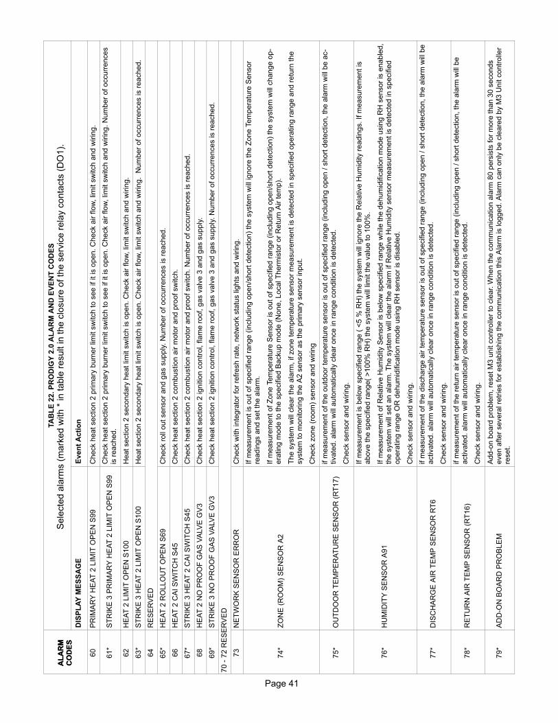
Page 41
Page 41
TA
BL
E 2
2. P
RO
DIG
Y 2
.0 A
LA
RM
AN
D E
VE
NT
CO
DE
S
Sele
cte
d a
larm
s (
mark
ed w
ith *
in table
result in the c
losure
of th
e s
erv
ice r
ela
y c
onta
cts
(D
O1).
A
LA
RM
CO
DE
S
Even
t A
cti
on
DIS
PL
AY
ME
SS
AG
E
AL
AR
MC
OD
ES
60
PR
IMA
RY
HE
AT
2 L
IMIT
OP
EN
S99
Check h
eat section 2
prim
ary
burn
er
limit s
witch to s
ee if it is o
pen. C
heck a
ir flo
w, lim
it s
witch a
nd w
irin
g.
61*
ST
RIK
E 3
PR
IMA
RY
HE
AT
2 L
IMIT
OP
EN
S99
Check h
eat section 2
prim
ary
burn
er
limit s
witch to s
ee if it is o
pen. C
heck a
ir flo
w, lim
it s
witch a
nd w
irin
g. N
um
ber
of occurr
ences
is r
eached.
62
HE
AT
2 L
IMIT
OP
EN
S100
Heat section 2
secondary
heat lim
it s
witch is o
pen. C
heck a
ir flo
w, lim
it s
witch a
nd w
irin
g.
63*
ST
RIK
E 3
HE
AT
2 L
IMIT
OP
EN
S100
Heat section 2
secondary
heat lim
it s
witch is o
pen. C
heck a
ir flo
w, lim
it s
witch a
nd w
irin
g. N
um
ber
of occurr
ences is r
eached.
64
RE
SE
RV
ED
65*
HE
AT
2 R
OLLO
UT
OP
EN
S69
Check r
oll
out sensor
and g
as s
upply
. N
um
ber
of occurr
ences is r
eached.
66
HE
AT
2 C
AI S
WIT
CH
S45
Check h
eat section 2
com
bustion a
ir m
oto
r and p
roof sw
itch.
67*
ST
RIK
E 3
HE
AT
2 C
AI S
WIT
CH
S45
Check h
eat section 2
com
bustion a
ir m
oto
r and p
roof sw
itch. N
um
ber
of occurr
ences is r
eached.
68
HE
AT
2 N
O P
RO
OF
GA
S V
ALV
E G
V3
Check h
eat section 2
ignitio
n c
ontr
ol, fla
me r
oof, g
as v
alv
e 3
and g
as s
upply
.
69*
ST
RIK
E 3
NO
PR
OO
F G
AS
VA
LV
E G
V3
Check h
eat section 2
ignitio
n c
ontr
ol, fla
me r
oof, g
as v
alv
e 3
and g
as s
upply
. N
um
ber
of occurr
ences is r
eached.
70 -
72 R
ES
ER
VE
D
73
NE
TW
OR
K S
EN
SO
R E
RR
OR
Check w
ith inte
gra
tor
for
refr
esh r
ate
, netw
ork
sta
tus lig
hts
and w
irin
g.
74*
ZO
NE
(R
OO
M)
SE
NS
OR
A2
If m
easure
ment is
out of specifie
d r
ange (
inclu
din
g o
pen/s
hort
dete
ction)
the s
yste
m w
ill ignore
the Z
one T
em
pera
ture
Sensor
readin
gs a
nd s
et th
e a
larm
.
If m
easure
ment of Z
one T
em
pera
ture
Sensor
is o
ut of specifie
d r
ange (
inclu
din
g o
pen/s
hort
dete
ction)
the s
yste
m w
ill c
hange o
p
era
ting m
ode to the s
pecifie
d B
ackup m
ode (
None, Local T
herm
isto
r or
Retu
rn A
ir tem
p).
The s
yste
m w
ill c
lear
the a
larm
, if z
one tem
pera
ture
sensor
measure
ment is
dete
cte
d in s
pecifie
d o
pera
ting r
ange a
nd r
etu
rn the
syste
m to m
onitoring the A
2 s
ensor
as the p
rim
ary
sensor
input.
Check z
one (
room
) sensor
and w
irin
g
75*
OU
TD
OO
R T
EM
PE
RA
TU
RE
SE
NS
OR
(R
T17)
if m
easure
ment of th
e o
utd
oor
tem
pera
ture
sensor
is o
ut of specifie
d r
ange (
inclu
din
g o
pen / s
hort
dete
ction, th
e a
larm
will
be
ac
tivate
d. ala
rm w
ill a
uto
matically
cle
ar
once in r
ange c
onditio
n is d
ete
cte
d.
Check s
ensor
and w
irin
g.
76*
HU
MID
ITY
SE
NS
OR
A91
If m
easure
ment is
belo
w s
pecifie
d r
ange (
<5 %
RH
) th
e s
yste
m w
ill ignore
the R
ela
tive H
um
idity r
eadin
gs. If m
easure
ment is
above the s
pecifie
d r
ange(
>100%
RH
) th
e s
yste
m w
ill lim
it the v
alu
e to 1
00%
.
If m
easure
ment of R
ela
tive H
um
idity S
ensor
is b
elo
w s
pecifie
d r
ange w
hile
the d
ehum
idific
ation m
ode u
sin
g R
H s
ensor
is e
nable
d,
the s
yste
m w
ill s
et an a
larm
. T
he s
yste
m w
ill c
lear
the a
larm
if R
ela
tive H
um
idity s
ensor
measure
ment is
dete
cte
d in s
pecifie
dopera
ting r
ange O
R d
ehum
idific
ation m
ode u
sin
g R
H s
ensor
is d
isable
d.
Check s
ensor
and w
irin
g.
77*
DIS
CH
AR
GE
AIR
TE
MP
SE
NS
OR
RT
6
if m
easure
ment of th
e d
ischarg
e a
ir tem
pera
ture
sensor
is o
ut of specifie
d r
ange (
inclu
din
g o
pen / s
hort
dete
ction, th
e a
larm
will
be
activate
d. ala
rm w
ill a
uto
matically
cle
ar
once in r
ange c
onditio
n is d
ete
cte
d.
Check s
ensor
and w
irin
g.
78*
RE
TU
RN
AIR
TE
MP
SE
NS
OR
(R
T16)
if m
easure
ment of th
e r
etu
rn a
ir tem
pera
ture
sensor
is o
ut of specifie
d r
ange (
inclu
din
g o
pen / s
hort
dete
ction, th
e a
larm
will
be
activate
d. ala
rm w
ill a
uto
matically
cle
ar
once in r
ange c
onditio
n is d
ete
cte
d.
Check s
ensor
and w
irin
g.
79*
AD
DO
N B
OA
RD
PR
OB
LE
M
Add-o
n b
oard
pro
ble
m, re
set M
3 u
nit c
ontr
olle
r to
cle
ar. W
hen the c
om
munic
ation a
larm
80 p
ers
ists
for
more
than 3
0 s
econds
even a
fter
severa
l re
trie
s for
esta
blis
hin
g the c
om
munic
ation this
Ala
rm is logged. A
larm
can o
nly
be c
leare
d b
y M
3 U
nit c
ontr
olle
rre
set.
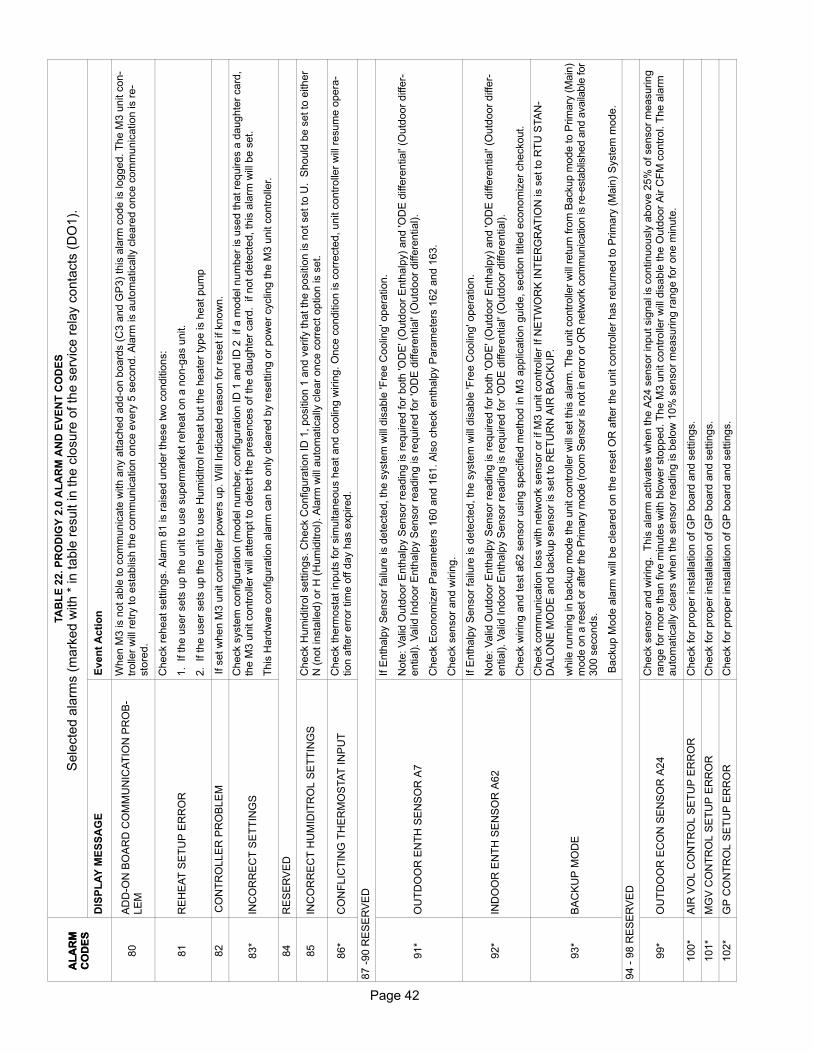
Page 42
TA
BL
E 2
2. P
RO
DIG
Y 2
.0 A
LA
RM
AN
D E
VE
NT
CO
DE
S
Sele
cte
d a
larm
s (
mark
ed w
ith *
in table
result in the c
losure
of th
e s
erv
ice r
ela
y c
onta
cts
(D
O1).
A
LA
RM
CO
DE
S
Even
t A
cti
on
DIS
PL
AY
ME
SS
AG
E
AL
AR
MC
OD
ES
80
AD
DO
N B
OA
RD
CO
MM
UN
ICA
TIO
N P
RO
B
LE
M
When M
3 is n
ot able
to c
om
munic
ate
with a
ny a
ttached a
dd-o
n b
oard
s (
C3 a
nd G
P3)
this
ala
rm c
ode is logged. T
he M
3 u
nit c
on
trolle
r w
ill r
etr
y to e
sta
blis
h the c
om
munic
ation o
nce e
very
5 s
econd. A
larm
is a
uto
matically
cle
are
d o
nce c
om
munic
ation is r
e
sto
red.
81
RE
HE
AT
SE
TU
P E
RR
OR
Check r
eheat settin
gs. A
larm
81 is r
ais
ed u
nder
these tw
o c
onditio
ns:
1. If th
e u
ser
sets
up the u
nit to u
se s
uperm
ark
et re
heat on a
nong
as u
nit.
2. If th
e u
ser
sets
up the u
nit to u
se H
um
iditro
l re
heat but th
e h
eate
r ty
pe is h
eat pum
p
82
CO
NT
RO
LLE
R P
RO
BLE
MIf s
et w
hen M
3 u
nit c
ontr
olle
r pow
ers
up. W
ill Indic
ate
d r
eason for
reset if k
now
n.
83*
INC
OR
RE
CT
SE
TT
ING
S
Check s
yste
m c
onfigura
tion (
model num
ber, c
onfigura
tion ID
1 a
nd ID
2 if a
model num
ber
is u
sed that re
quires a
daughte
r card
,th
e M
3 u
nit c
ontr
olle
r w
ill a
ttem
pt to
dete
ct th
e p
resences o
f th
e d
aughte
r card
. if not dete
cte
d, th
is a
larm
will
be s
et.
This
Hard
ware
configura
tion a
larm
can b
e o
nly
cle
are
d b
y r
esettin
g o
r pow
er
cyclin
g the M
3 u
nit c
ontr
olle
r.
84
RE
SE
RV
ED
85
INC
OR
RE
CT
HU
MID
ITR
OL S
ET
TIN
GS
Check H
um
iditro
l settin
gs. C
heck C
onfigura
tion ID
1, positio
n 1
and v
erify
that th
e p
ositio
n is n
ot set to
U. S
hould
be s
et to
either
N (
not in
sta
lled)
or
H (
Hum
iditro
l). A
larm
will
auto
matically
cle
ar
once c
orr
ect option is s
et.
86*
CO
NF
LIC
TIN
G T
HE
RM
OS
TA
T IN
PU
TC
heck therm
osta
t in
puts
for
sim
ultaneous h
eat and c
oolin
g w
irin
g. O
nce c
onditio
n is c
orr
ecte
d, unit c
ontr
olle
r w
ill r
esum
e o
pera
tion a
fter
err
or
tim
e o
ff d
ay h
as e
xpired.
87 -
90 R
ES
ER
VE
D
91*
OU
TD
OO
R E
NT
H S
EN
SO
R A
7
If E
nth
alp
y S
ensor
failu
re is d
ete
cte
d, th
e s
yste
m w
ill d
isable
'Fre
e C
oolin
g' o
pera
tion.
Note
: V
alid
Outd
oor
Enth
alp
y S
ensor
readin
g is r
equired for
both
'OD
E' (
Outd
oor
Enth
alp
y)
and 'O
DE
diffe
rential'
(Outd
oor
diffe
rential). V
alid
Indoor
Enth
alp
y S
ensor
readin
g is r
equired for
'OD
E d
iffe
rential'
(Outd
oor
diffe
rential).
Check E
conom
izer
Para
mete
rs 1
60 a
nd 1
61. A
lso c
heck e
nth
alp
y P
ara
mete
rs 1
62 a
nd 1
63.
Check s
ensor
and w
irin
g.
92*
IND
OO
R E
NT
H S
EN
SO
R A
62
If E
nth
alp
y S
ensor
failu
re is d
ete
cte
d, th
e s
yste
m w
ill d
isable
'Fre
e C
oolin
g' o
pera
tion.
Note
: V
alid
Outd
oor
Enth
alp
y S
ensor
readin
g is r
equired for
both
'OD
E' (
Outd
oor
Enth
alp
y)
and 'O
DE
diffe
rential'
(Outd
oor
diffe
rential). V
alid
Indoor
Enth
alp
y S
ensor
readin
g is r
equired for
'OD
E d
iffe
rential'
(Outd
oor
diffe
rential).
Check w
irin
g a
nd test a62 s
ensor
usin
g s
pecifie
d m
eth
od in M
3 a
pplic
ation g
uid
e, section title
d e
conom
izer
checkout.
93*
BA
CK
UP
MO
DE
Check c
om
munic
ation loss w
ith n
etw
ork
sensor
or
if M
3 u
nit c
ontr
olle
r If N
ET
WO
RK
IN
TE
RG
RA
TIO
N is s
et to
RT
U S
TA
N
DA
LO
NE
MO
DE
and b
ackup s
ensor
is s
et to
RE
TU
RN
AIR
BA
CK
UP.
while
runnin
g in b
ackup m
ode the u
nit c
ontr
olle
r w
ill s
et th
is a
larm
. T
he u
nit c
ontr
olle
r w
ill r
etu
rn fro
m B
ackup m
ode to P
rim
ary
(M
ain
)m
ode o
n a
reset or
after
the P
rim
ary
mode (
room
Sensor
is n
ot in
err
or
or
OR
netw
ork
com
munic
atio
n is
re-e
sta
blis
hed a
nd a
vaila
ble
for
300 s
econds.
Backup M
ode a
larm
will
be c
leare
d o
n the r
eset O
R a
fter
the u
nit c
ontr
olle
r has r
etu
rned to P
rim
ary
(M
ain
) S
yste
m m
ode.
94 -
98 R
ES
ER
VE
D
99*
OU
TD
OO
R E
CO
N S
EN
SO
R A
24
Check s
ensor
and w
irin
g. T
his
ala
rm a
ctivate
s w
hen the A
24 s
ensor
input sig
nal is
continuously
above 2
5%
of sensor
measuring
range for
more
than fiv
e m
inute
s w
ith b
low
er
sto
pped. T
he M
3 u
nit c
ontr
olle
r w
ill d
isable
the O
utd
oor
Air C
FM
contr
ol. T
he a
larm
auto
matically
cle
ars
when the s
ensor
readin
g is b
elo
w 1
0%
sensor
measuring r
ange for
one m
inute
.
100*
AIR
VO
L C
ON
TR
OL S
ET
UP
ER
RO
RC
heck for
pro
per
insta
llation o
f G
P b
oard
and s
ettin
gs.
101*
MG
V C
ON
TR
OL S
ET
UP
ER
RO
RC
heck for
pro
per
insta
llation o
f G
P b
oard
and s
ettin
gs.
102*
GP
CO
NT
RO
L S
ET
UP
ER
RO
RC
heck for
pro
per
insta
llation o
f G
P b
oard
and s
ettin
gs.

Page 43
Page 43
TA
BL
E 2
2. P
RO
DIG
Y 2
.0 A
LA
RM
AN
D E
VE
NT
CO
DE
S
Sele
cte
d a
larm
s (
mark
ed w
ith *
in table
result in the c
losure
of th
e s
erv
ice r
ela
y c
onta
cts
(D
O1).
A
LA
RM
CO
DE
S
Even
t A
cti
on
DIS
PL
AY
ME
SS
AG
E
AL
AR
MC
OD
ES
103*
AD
VA
NC
ED
CO
NT
RO
L S
ET
UP
ER
RO
RC
heck M
3 u
nit c
ontr
olle
r C
onfigura
tion ID
1 s
ettin
gs.
104 -
105 R
ES
ER
VE
D
106*
BU
ILD
ING
PR
ES
S S
EN
SO
R A
34
Check s
ensor
and w
irin
g.
107*
DU
CT
SU
PP
LY
PR
ES
S S
EN
SO
R A
30
Check s
ensor
and w
irin
g.
The u
nit c
ontr
olle
r w
ill s
et S
upply
Air S
tatic P
ressure
Sensor
(A30)
err
or
sta
tus if:
�In
put sig
nal is
above 4
.9"
wc for
more
than 3
0 s
econds.
�O
R
�In
put sig
nal is
belo
w 0
.1"w
c 2
0 s
econds a
fter
the b
low
er
has s
tart
ed w
ith s
ettin
g a
t or
above B
low
er
Outp
ut
Sta
tic D
uct A
larm
Check.
The M
3 u
nit c
ontr
olle
r w
ill c
lear
the S
upply
Air S
tatic P
ressure
Sensor
(A30)
err
or
sta
tus a
nd a
larm
after
the e
xpiration o
f E
rror
Tim
e O
FF
dela
y.
108
DU
CT
SU
PP
LY
HIG
H P
RE
SS
SE
NS
OR
A30
Check s
ensor
and w
irin
g.
The u
nit c
ontr
olle
r w
ill s
hutd
ow
n o
pera
tion for
Err
or
OF
F tim
e (
Para
mete
r 110)
if s
upply
supply
air s
tatic p
ressure
exceeds S
up
ply
sta
tic s
hutd
ow
n s
etp
oin
t fo
r 20 s
econds (
defa
ult)
Para
mete
r 42.
The u
nit c
ontr
olle
r w
ill c
lear
Hig
h S
upply
Sta
tic (
Duct)
Pre
ssure
after
Err
or
OF
F T
ime h
as e
xpired a
nd s
tatic d
uct pre
ssure
is b
elo
w
Supply
Sta
tic S
et P
oin
t S
hutd
ow
n.
109*
ST
RIK
E 3
DU
CT
SU
PP
LY
PR
ES
S S
EN
SO
RA
30
Check s
ensor
and w
irin
g.
Pro
dig
y c
ontr
olle
r shall
"locko
ut"
a u
nit o
pera
tion a
fter
the M
ax S
tatic D
uct P
ressure
Occurr
ences h
ave o
ccurr
ed o
f S
upply
Sta
tic
Pre
ssure
Sensor
Err
or
(ala
rm 1
07)
and/o
r H
igh S
upply
Sta
tic (
Duct)
Pre
ssure
(ala
rm 1
08).
User
shall
be a
ble
to c
lear
Supply
Sta
tic P
ressure
lockout &
ala
rm v
ia U
ser
Inte
rface. S
upply
Sta
tic P
ressure
lockout &
ala
rm s
hall
be c
leare
d a
fter
the P
rodig
y c
ontr
olle
r re
set.
The n
um
ber
of str
ikes is thre
e b
y d
efa
ult. this
can b
e c
hanged u
sin
g p
ara
mete
r 43. O
ptional occurr
ence s
ettin
g is 1
to 7
.
110
WA
ITIN
G O
N N
ET
WO
RK
DA
TA
Check n
etw
ork
or
com
fort
sensor
and w
irin
g.
111
PR
OF
ILE
ER
RO
RC
onfigura
tion p
rofile
unre
covera
ble
. S
ettin
gs m
ay h
ave c
hanged.
112 -
120
RE
SE
RV
ED
121*
LIN
E F
RE
Q D
OE
S N
OT
MA
TC
H U
NIT
CO
NF
IG
Pow
er
sourc
e lin
e fre
quency is d
ete
rmin
ed b
y the e
nte
red m
odel num
ber. T
his
ala
rm is e
nable
d b
y the P
haseV
oltage D
ete
ction
featu
re. M
3 u
nit c
ontr
olle
r does n
ot have a
n a
uto
matic c
learing m
eth
od, unit p
ow
er
cycle
or
reset w
ill b
e r
equired to r
e-e
valu
ate
the
phase s
equence a
gain
.
122*
24V
AC
PR
IMA
RY
VO
LTA
GE
LO
W
Low
outp
ut voltage o
n T
1 tra
nsfo
rmer. a
larm
set w
hen 2
4V
AC
voltage low
if calc
ula
ted R
MS
voltage is b
elo
w low
voltage a
larm
thre
shold
for
more
than tw
o s
econds. S
yste
m w
ill s
top u
nit o
pera
tions (
coolin
g, heating a
nd v
entila
tion).
Low
voltage thre
shold
is
18V
AC
.
The M
3 u
nit c
ontr
olle
r w
ill c
lear
ala
rm 2
4V
AC
Voltage L
ow
if calc
ula
ted R
MS
voltage is a
bove L
ow
Voltage A
larm
Thre
shold
+ 1
VA
C for
more
than tw
o s
econds. A
fter
the low
24V
AC
ala
rm h
as b
een c
leare
d, th
e M
3 u
nit c
ontr
olle
r w
ill ignore
all
serv
ice d
e
mands u
ntil th
e E
rror
Tim
e O
ff D
ela
y h
as e
xpired.
123*
24V
AC
PR
IMA
RY
VO
LTA
GE
HIG
H
Hig
h o
utp
ut voltage o
n T
1 tra
nsfo
rmer. a
larm
set w
hen 2
4V
AC
voltage h
igh if calc
ula
ted R
MS
voltage is b
elo
w low
voltage a
larm
thre
shold
for
more
than tw
o s
econds. S
yste
m w
ill s
top u
nit o
pera
tions (
coolin
g, heating a
nd v
entila
tion).
Low
voltage thre
shold
is
30V
AC
.
The M
3 u
nit c
ontr
olle
r w
ill c
lear
ala
rm 2
4V
AC
Voltage h
igh if calc
ula
ted R
MS
voltage is a
bove H
igh V
oltage A
larm
Thre
shold
+ 1
VA
C for
more
than tw
o s
econds. A
fter
the H
IGH
24V
AC
ala
rm h
as b
een c
leare
d, th
e M
3 u
nit c
ontr
olle
r w
ill ignore
all
serv
ice d
e
mands u
ntil th
e E
rror
Tim
e O
ff D
ela
y h
as e
xpired.
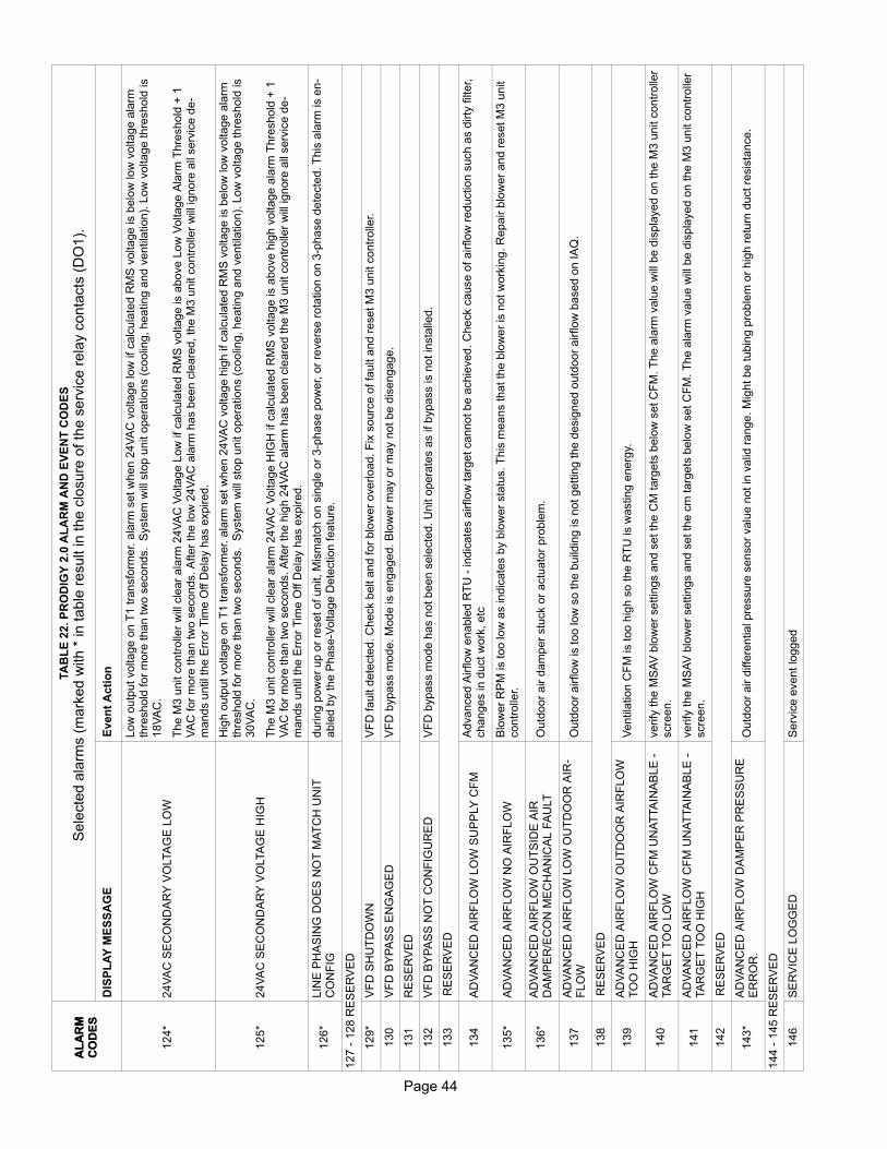
Page 44
TA
BL
E 2
2. P
RO
DIG
Y 2
.0 A
LA
RM
AN
D E
VE
NT
CO
DE
S
Sele
cte
d a
larm
s (
mark
ed w
ith *
in table
result in the c
losure
of th
e s
erv
ice r
ela
y c
onta
cts
(D
O1).
A
LA
RM
CO
DE
S
Even
t A
cti
on
DIS
PL
AY
ME
SS
AG
E
AL
AR
MC
OD
ES
124*
24V
AC
SE
CO
ND
AR
Y V
OLTA
GE
LO
W
Low
outp
ut voltage o
n T
1 tra
nsfo
rmer. a
larm
set w
hen 2
4V
AC
voltage low
if calc
ula
ted R
MS
voltage is b
elo
w low
voltage a
larm
thre
shold
for
more
than tw
o s
econds. S
yste
m w
ill s
top u
nit o
pera
tions (
coolin
g, heating a
nd v
entila
tion).
Low
voltage thre
shold
is
18V
AC
.
The M
3 u
nit c
ontr
olle
r w
ill c
lear
ala
rm 2
4V
AC
Voltage L
ow
if calc
ula
ted R
MS
voltage is a
bove L
ow
Voltage A
larm
Thre
shold
+ 1
VA
C for
more
than tw
o s
econds. A
fter
the low
24V
AC
ala
rm h
as b
een c
leare
d, th
e M
3 u
nit c
ontr
olle
r w
ill ignore
all
serv
ice d
e
mands u
ntil th
e E
rror
Tim
e O
ff D
ela
y h
as e
xpired.
125*
24V
AC
SE
CO
ND
AR
Y V
OLTA
GE
HIG
H
Hig
h o
utp
ut voltage o
n T
1 tra
nsfo
rmer. a
larm
set w
hen 2
4V
AC
voltage h
igh if calc
ula
ted R
MS
voltage is b
elo
w low
voltage a
larm
thre
shold
for
more
than tw
o s
econds. S
yste
m w
ill s
top u
nit o
pera
tions (
coolin
g, heating a
nd v
entila
tion).
Low
voltage thre
shold
is
30V
AC
.
The M
3 u
nit c
ontr
olle
r w
ill c
lear
ala
rm 2
4V
AC
Voltage H
IGH
if calc
ula
ted R
MS
voltage is a
bove h
igh v
oltage a
larm
Thre
shold
+ 1
VA
C for
more
than tw
o s
econds. A
fter
the h
igh 2
4V
AC
ala
rm h
as b
een c
leare
d the M
3 u
nit c
ontr
olle
r w
ill ignore
all
serv
ice d
e
mands u
ntil th
e E
rror
Tim
e O
ff D
ela
y h
as e
xpired.
126*
LIN
E P
HA
SIN
G D
OE
S N
OT
MA
TC
H U
NIT
CO
NF
IGduring p
ow
er
up o
r re
set of unit, M
ism
atc
h o
n s
ingle
or
3p
hase p
ow
er, o
r re
vers
e r
ota
tion o
n 3
phase d
ete
cte
d. T
his
ala
rm is e
n
able
d b
y the P
haseV
oltage D
ete
ction featu
re.
127 -
128 R
ES
ER
VE
D
129*
VF
D S
HU
TD
OW
NV
FD
fault d
ete
cte
d. C
heck b
elt a
nd for
blo
wer
overload. F
ix s
ourc
e o
f fa
ult a
nd r
eset M
3 u
nit c
ontr
olle
r.
130
VF
D B
YP
AS
S E
NG
AG
ED
VF
D b
ypass m
ode. M
ode is e
ngaged. B
low
er
may o
r m
ay n
ot be d
isengage.
131
RE
SE
RV
ED
132
VF
D B
YP
AS
S N
OT
CO
NF
IGU
RE
DV
FD
bypass m
ode h
as n
ot been s
ele
cte
d. U
nit o
pera
tes a
s if bypass is n
ot in
sta
lled.
133
RE
SE
RV
ED
134
AD
VA
NC
ED
AIR
FLO
W L
OW
SU
PP
LY
CF
MA
dvanced A
irflow
enable
d R
TU
indic
ate
s a
irflow
targ
et cannot be a
chie
ved. C
heck c
ause o
f airflow
reduction s
uch a
s d
irty
filt
er,
changes in d
uct w
ork
, etc
135*
AD
VA
NC
ED
AIR
FLO
W N
O A
IRF
LO
WB
low
er
RP
M is too low
as indic
ate
s b
y b
low
er
sta
tus. T
his
means that th
e b
low
er
is n
ot w
ork
ing. R
epair b
low
er
and r
eset M
3 u
nit
contr
olle
r.
136*
AD
VA
NC
ED
AIR
FLO
W O
UT
SID
E A
IRD
AM
PE
R/E
CO
N M
EC
HA
NIC
AL F
AU
LT
Outd
oor
air d
am
per
stu
ck o
r actu
ato
r pro
ble
m.
137
AD
VA
NC
ED
AIR
FLO
W L
OW
OU
TD
OO
R A
IR
FLO
WO
utd
oor
airflow
is too low
so the b
uild
ing is n
ot gettin
g the d
esig
ned o
utd
oor
airflow
based o
n IA
Q.
138
RE
SE
RV
ED
139
AD
VA
NC
ED
AIR
FLO
W O
UT
DO
OR
AIR
FLO
WT
OO
HIG
HV
entila
tion C
FM
is too h
igh s
o the R
TU
is w
asting e
nerg
y.
140
AD
VA
NC
ED
AIR
FLO
W C
FM
UN
AT
TA
INA
BLE
TA
RG
ET
TO
O L
OW
verify
the M
SA
V b
low
er
settin
gs a
nd s
et th
e C
M targ
ets
belo
w s
et C
FM
. T
he a
larm
valu
e w
ill b
e d
ispla
yed o
n the M
3 u
nit c
ontr
olle
rscre
en.
141
AD
VA
NC
ED
AIR
FLO
W C
FM
UN
AT
TA
INA
BLE
TA
RG
ET
TO
O H
IGH
verify
the M
SA
V b
low
er
settin
gs a
nd s
et th
e c
m targ
ets
belo
w s
et C
FM
. T
he a
larm
valu
e w
ill b
e d
ispla
yed o
n the M
3 u
nit c
ontr
olle
rscre
en.
142
RE
SE
RV
ED
143*
AD
VA
NC
ED
AIR
FLO
W D
AM
PE
R P
RE
SS
UR
EE
RR
OR
.O
utd
oor
air d
iffe
rential pre
ssure
sensor
valu
e n
ot in
valid
range. M
ight be tubin
g p
roble
m o
r hig
h r
etu
rn d
uct re
sis
tance.
144 -
145 R
ES
ER
VE
D
146
SE
RV
ICE
LO
GG
ED
Serv
ice e
vent lo
gged

Page 45
Page 45
TA
BL
E 2
2. P
RO
DIG
Y 2
.0 A
LA
RM
AN
D E
VE
NT
CO
DE
S
Sele
cte
d a
larm
s (
mark
ed w
ith *
in table
result in the c
losure
of th
e s
erv
ice r
ela
y c
onta
cts
(D
O1).
A
LA
RM
CO
DE
S
Even
t A
cti
on
DIS
PL
AY
ME
SS
AG
E
AL
AR
MC
OD
ES
147*
OA
DA
MP
ER
ER
RO
RD
uring fre
e c
oolin
g d
am
per
is n
ot m
odula
ting.
148*
AD
VA
NC
ED
AIR
FLO
W C
ON
FIG
ER
RO
RE
conom
izer
should
be insta
lled a
nd b
low
er
should
be E
CM
type.
149*
OU
TD
OO
R A
IR D
IFF
PR
ES
SU
RE
SE
NS
OR
ER
RO
RC
heck o
utd
oor
air d
am
per
diffe
rential pre
ssure
sensor
and w
irin
g.
150*
NO
T E
CO
NO
MIZ
ING
WH
EN
OU
TD
OO
R A
IR IS
SU
ITA
BLE
May b
e d
ue to the d
am
per
moto
r bein
g u
nplu
gged o
r dis
connecte
d.
151*
EC
ON
OM
IZIN
G W
HE
N O
UT
DO
OR
AIR
IS
NO
TS
UIT
AB
LE
my b
e d
ue to d
am
per
moto
r bein
g b
locked o
pen a
nd n
ot clo
sin
g.
152 -
164
RE
SE
RV
ED
165
EC
ON
OM
IZE
R N
OT
CO
NF
IGU
RE
Dconfigura
tion id 1
, positio
n 2
is s
et to
u. s
ele
ct applic
able
option u
sin
g s
etu
p/insta
ll w
izard
.
166
CA
I P
RE
SS
UR
E S
WIT
CH
ST
UC
K C
LO
SE
D
GV
1T
his
ala
rm w
ill o
ccur
when the c
om
bustion a
ir p
ressure
sw
itch (
S18)
is d
ete
cte
d a
s c
losed im
media
tely
after
the furn
ace d
em
and
rela
y is e
nerg
ized a
nd b
efo
re the c
om
bustion a
ir b
low
er
is e
nerg
ized. G
as v
alv
e 1
.
167
CA
I P
RE
SS
UR
E S
WIT
CH
ST
UC
K C
LO
SE
D
GV
2T
his
ala
rm w
ill o
ccur
when the c
om
bustion a
ir p
ressure
sw
itch (
S45)
is d
ete
cte
d a
s c
losed im
media
tely
after
the furn
ace d
em
and
rela
y is e
nerg
ized a
nd b
efo
re the c
om
bustion a
ir b
low
er
is e
nerg
ized. G
as v
alv
e 2
.
168*
CO
MB
US
TIO
N A
IR S
W N
OT
OP
EN
LO
CK
OU
T
GV
1S
yste
m locked o
ut due to S
45 s
witch c
losed a
nd a
specific
num
ber
occurr
ences d
ete
cte
d b
ased o
n P
ara
mete
r 72 (
MA
X C
AI N
OP
RF
OC
C)
settin
g d
uring a
sin
gle
cycle
.169*
CO
MB
US
TIO
N A
IR S
W N
OT
OP
EN
LO
CK
OU
T
GV
2
170
PO
WE
R E
XH
AU
ST
NO
T C
ON
FIG
UR
ED
Configura
tion ID
1, positio
n 3
is s
et as U
(unconfigure
d).
171
PO
WE
R E
XH
AU
ST
CO
NF
IGU
RA
TIO
N E
RR
OR
Configura
tion ID
1, positio
n 4
is s
et corr
ectly.
if p
ositio
n 3
is c
onfigure
d then p
ositio
n 4
must be a
lso.
172
AD
VA
NC
ED
AIR
FLO
W C
ON
TR
OL N
OT
CO
NF
IGU
RE
DIf C
onfigura
tion ID
1, positio
n 6
- b
low
er
VF
D b
ypass is s
et to
A o
r M
, th
en C
onfigura
tion ID
2, positio
n 1
must be s
et to
C o
r D
.
173
AIR
FLO
W S
WIT
CH
CO
NF
IG E
RR
OR
Verify
that C
onfigura
tion ID
2, positio
n 1
is s
et corr
ectly.
174
ZO
NE
(R
OO
M)
BY
PA
SS
DA
MP
ER
CO
NF
IGU
R
AT
ION
ER
RO
RR
oom
bypass d
am
per
opera
tion is o
nly
com
patible
with c
ab b
low
ers
. pro
dig
y w
ill o
nly
allo
w z
one b
ypass u
nit o
pera
tion if configur
ation ID
1 is s
et to
insta
lled for
units w
ith B
or
T type b
low
ers
. a
larm
will
auto
matically
cle
ar
when c
onfigura
tion c
onflic
t is
corr
ecte
d.
175
INV
ALID
LO
AD
SH
ED
DIN
G IN
PU
TC
ON
FIG
UR
AT
ION
Ala
rm w
ill o
ccur
if load s
heddin
g input is
share
d w
ith o
ther
optional devic
es o
r in
puts
, fo
r exam
ple
- g
lobal, b
low
er
overload, dra
inpan o
verf
low
, etc
.
176
SB
US
RE
CE
IVE
D A
N O
BS
OLE
TE
M3
CO
MM
AN
DT
his
ala
rm o
ccurs
when a
SB
US
maste
r devic
e s
ends a
M2 s
tyle
com
mand to the M
3 u
nit c
ontr
olle
r. T
he a
larm
is im
media
tely
cle
are
d a
nd a
his
tory
of th
e e
vent is
sto
red.
177
MO
DE
L N
UM
BE
R N
OT
DE
FIN
ED
Mis
sin
g m
odel configura
tion d
ata
. r
un s
etu
p >
insta
ll and c
om
ple
te m
odel num
ber
info
rmation.
178 -
181
RE
SE
RV
ED
182
ULT
RA
: S
UC
TIO
N P
RE
SS
UR
E S
EN
SO
RE
RR
OR
Pro
dig
y p
rovid
es 0
-5V
DC
analo
g input fo
r th
e s
uction p
ressure
sensor. S
ensor
outp
ut is
connecte
d to P
333, pin
1. valid
suction
pre
ssure
range is 0
to 3
00 p
sig
.
If S
uction P
ressure
Sensor
is d
ete
cte
d o
n U
ltra
unit falls
belo
w the 3
0 p
sig
then P
rodig
y w
ill a
ssum
e that th
e P
ressure
Sensor
sensor
is faulty a
nd ignore
Pre
ssure
Sensor
readin
gs. ala
rm w
ill a
uto
matically
cle
ar
once input is
within
norm
al opera
ting r
ang
e.
The a
larm
ing v
alu
e indic
ate
s w
hic
h s
uction p
ressure
sensor
faile
d.
0 -
Tandem
1 S
uction P
ressure
Sensor
Failu
re1 -
Tandem
2 S
uction P
ressure
Sensor
Failu
re

Page 46
TA
BL
E 2
2. P
RO
DIG
Y 2
.0 A
LA
RM
AN
D E
VE
NT
CO
DE
S
Sele
cte
d a
larm
s (
mark
ed w
ith *
in table
result in the c
losure
of th
e s
erv
ice r
ela
y c
onta
cts
(D
O1).
A
LA
RM
CO
DE
S
Even
t A
cti
on
DIS
PL
AY
ME
SS
AG
E
AL
AR
MC
OD
ES
182
ULT
RA
: S
UC
TIO
N P
RE
SS
UR
E S
EN
SO
RE
RR
OR
Pro
dig
y p
rovid
es 0
-5V
DC
analo
g input fo
r th
e s
uction p
ressure
sensor. S
ensor
outp
ut is
connecte
d to P
333, pin
1. valid
suction
pre
ssure
range is 0
to 3
00 p
sig
.
If S
uction P
ressure
Sensor
is d
ete
cte
d o
n U
ltra
unit falls
belo
w the 3
0 p
sig
then P
rodig
y w
ill a
ssum
e that th
e P
ressure
Sensor
sensor
is faulty a
nd ignore
Pre
ssure
Sensor
readin
gs. ala
rm w
ill a
uto
matically
cle
ar
once input is
within
norm
al opera
ting r
ang
e.
The a
larm
ing v
alu
e indic
ate
s w
hic
h s
uction p
ressure
sensor
faile
d.
0 -
Tandem
1 S
uction P
ressure
Sensor
Failu
re1 -
Tandem
2 S
uction P
ressure
Sensor
Failu
re
182
ULT
RA
: S
UC
TIO
N P
RE
SS
UR
ES
EN
SO
R E
RR
OR
Pro
dig
y p
rovid
es 0
-5V
DC
analo
g input fo
r th
e s
uction p
ressure
sensor. S
ensor
outp
ut is
connecte
d to P
333, pin
1. valid
suction
pre
ssure
range is 0
to 3
00 p
sig
.
If S
uction P
ressure
Sensor
is d
ete
cte
d o
n U
ltra
unit falls
belo
w the 3
0 p
sig
then P
rodig
y w
ill a
ssum
e that th
e P
ressure
Sensor
sensor
is faulty a
nd ignore
Pre
ssure
Sensor
readin
gs. ala
rm w
ill a
uto
matically
cle
ar
once input is
within
norm
al opera
ting r
ang
e.
The a
larm
ing v
alu
e indic
ate
s w
hic
h s
uction p
ressure
sensor
faile
d.
0 -
Tandem
1 S
uction P
ressure
Sensor
Failu
re1 -
Tandem
2 S
uction P
ressure
Sensor
Failu
re
183
ULT
RA
: C
OM
PR
ES
SO
R 1
SU
MP
TE
MP
ER
AT
UR
E S
EN
SO
R E
RR
OR
Ala
rm w
ill o
ccur
when a
n o
pen o
r short
conditio
n is d
ete
cte
d. A
larm
will
als
o o
ccur
when u
nit c
ontr
olle
r via
the tem
pera
ture
se
nsor
dete
cts
an o
ut of ra
nge. V
alid
range is
30°F
to 1
50°F
. P
ossib
le c
auses a
re faulty tem
pera
ture
sensor
/ circuit o
r im
pro
per
insta
llation.
The a
larm
ing v
alu
e indic
ate
s w
hic
h C
om
pre
ssor
Sum
p T
em
p s
ensor
faile
d.
0 -
Tandem
1 C
om
pre
ssor
1 S
um
p T
em
p S
ensor
Failu
re1 -
Tandem
2 C
om
pre
ssor
1 S
um
p T
em
p S
ensor
Failu
re
184
ULT
RA
: C
OM
PR
ES
SO
R 2
SU
MP
TE
MP
ER
AT
UR
E S
EN
SO
R E
RR
OR
Ala
rm w
ill o
ccur
when a
n o
pen o
r short
conditio
n is d
ete
cte
d. A
larm
will
als
o o
ccur
when u
nit c
ontr
olle
r via
the tem
pera
ture
se
nsor
dete
cts
an o
ut of ra
nge. V
alid
range is
30°F
to 1
50°F
. P
ossib
le c
auses a
re faulty tem
pera
ture
sensor
/ circuit o
r im
pro
per
insta
llation.
The a
larm
ing v
alu
e indic
ate
s w
hic
h C
om
pre
ssor
Sum
p T
em
p s
ensor
faile
d.
0 -
Tandem
1 C
om
pre
ssor
2 S
um
p T
em
p S
ensor
Failu
re1 -
Tandem
2 C
om
pre
ssor
2 S
um
p T
em
p S
ensor
Failu
re
185
EN
GIN
EE
RIN
G U
SE
ON
LY.
186*
BLO
WE
R M
OT
OR
FA
ULT
In s
yste
ms w
ith E
BM
blo
wer, p
rodig
y s
hall
sta
rt m
onitoring the m
oto
r ala
rm o
utp
ut (n
orm
ally
clo
sed r
ela
y c
onta
ct)
ten s
econds
after
blo
wer
com
mand is s
ent. T
he M
3 u
nit c
ontr
olle
r w
ill s
top u
nit o
pera
tion if fa
ult c
onditio
ns (
rela
y c
onta
ct open
logic
input
hig
h)
are
dete
cte
d.
No
te: M
oto
r ala
rm is w
ired in P
2597
; share
d w
ith V
FD
ala
rm a
nd E
CM
blo
wer
rpm
input. A
larm
will
cle
ar
when inr
ange
tem
pera
ture
is d
ete
cte
d.

Page 47
Page 47
CONTROLLER SIGNAL REFERENCES
M3 UNIT CONTROLLER
Table 1. P259 Blower ECM Motor
Pin#
Label Description Type
1ODF /PWM 1
OUTDOOR FAN PWM1 PWM
2ODF /PWM 2
OUTDOOR FAN PWM2 PWM
3 GND DIGITIAL GROUND GND
4IDB / PWM
/ VOA-BOX: INDOOR BLOWER PWM PWM
* MSAV / VAV: VFD VOLT OUT 0-10 VAC OUT
* EBM ULTRA: VOLT OUT 0-10 VAC OUT
* ZONE: DAMPER ACUATOR (CAV) 0-10 VAC
5MSAVRELAY
*A BOX: 2ND STAGECOMPRESSOR 1
24VAC DO
*MSAV / VAV: EXHAUST 2ND BYPASS
24VAC DO
6 GND DIGITAL GROUND GND
7 IDB A-BOX: IDB FEEDBACK 5VDC
*MSAV / VAV / ULTRA B-C ALARMCONTACT (MUST BE WIRED TOGND)
5VDC
8 V BIAS V-BIAS 18VDC
Table 2. P262 Economizer Control
Pin#
Label Description Type
1 T1 24VAC POWER 24VAC
2 GND DIGITAL GROUND 24VAC COM
3 VOT DAMPER CONTROL 2-10VDC DO
4 DPOS DAMPER POSITION FEEDBACK 2-10VDC DI
5 GND DIGITAL GROUNDRES 0-5VDC
6 RT16 + RETURN AIR TEMP
7 A7 S OUTDOOR ENTHALPY SENSOR 4-20 mA AI
8 18VDC 18VDC POWER 18VDC
9 A62 S INDOOR ENTHALPY SENSOR 4-20 mA AI
10 A173 SMOKE DETECTOR 24VAC DI
11 T1 SMOKE DETECTOR 24VAC24VACPOWER12 COM
SMOKE DETECTOR 24VACCOMMON
Table 3. P263 High and Low Pressure
Pin#
Label Description Type
1 UTS2ULTRA SUMP TEMPCOMPRESSOR 2 RES 0-5VDC
2 GND GROUND
3 S4HIGH PRESSURECOMPRESSOR 1
SW 24VAC
4 T1 24VAC POWER 24VAC
5 S87LOW PRESSURE COMPRESSOR1 NC
SW 24VAC
6 S7HIGH PRESSURECOMPRESSOR 2
SW 24VAC
7 T1 24VAC POWER 24VAC
8 S88LOW PRESSURE COMPRESSOR2
SW 24VAC
Table 4. P264 Blower Deck Area
Pin#
Label Description Type
1 RT6 DISCHARGE AIR TEMPRES 0-5VDC
2 GND DIGITAL GROUND
3 S49 FREEZESTAT 1 (NC) SW 5VDC
4 VSS 5VDC 5VDC
5 S50 FREEZESTAT 2 (NC) SW 5VDC
6 S52 AIR FLOW SWITCH (NO) SW 5VDC
7 VSS 5VDC 5VDC
8 S27 DIRTY FILTER SWITCH (NO) SW 5VDC
Table 5. P265 Contactors / Relays
Pin#
Label Description Type
1 COM 24VAC COMMON 24VAC COM
2 K1 CONTACTOR COMPRESSOR 1 24VAC DO
3 K2 CONTACTOR COMPRESSOR 2 24VAC DO
4 K3 CONTACTOR BLOWER 24VAC DO
* A-BOX INDOOR BLOWER LOW 24VAC DO
5 COM 24VAC COMMON 24VAC COM
6 K10 RELAY OUTDOOR FAN 1 24VAC DO
*RELAY K191 ULTRA:CRANKCASE HEATER
24VAC DO
7 K68 RELAY OUTDOOR FAN 2 24VAC DO
* A-BOX: INDOOR BLOWER HIGH 24VAC DO
*RELAY K196 ULTRA: CRANKCASE HEATER
24VAC DO
8 COM 24VAC COMMON 24VAC COM
9 K13RELAY COMBUSTION AIRBLOWER 1
24VAC DO
10 COM 24VAC COMMON 24VAC COM
11 K85 RELAY EXHAUST FAN 24VAC DO
Table 6. P266 Heating Control and Damper ΔP Sensor
Pin#
Label Description Type
1 COM 24VAC COMM 24VAC COM
2 A3, K15 HEAT 1, ELECTRIC HEAT 1 24VAC DO
3 W2, K16 HEAT 2, ELECTRIC HEAT 2 24VAC DO
4 DDPSDAMPER DIFFER. PRESSURESENSOR
0-5VDC
5 GND GROUND GND
6 5VDC 5VDC SUPPLY 5VDC
Table 7. P267 Outdoor Fan Area
Pin#
Label Description Type
1 RT17 OUTDOOR AIR TEMPRES 0-5VDC
2 GND DIGITAL GROUND
3 S11 LOW PRESSURE FAN 1 SW 24VAC
4 R 24VAC 24VAC DO
5 S84 LOW PRESSURE FAN 2 SW 24VAC
6 A30 STATIC DUCT PRESSURE 10VDC
7 GND GROUND GND
8 5VDC 5VDC SUPPLY 5VDC

Page 48
Table 8. P268 Power
Pin#
Label Description Type
1 T1-124VAC POWER TRANSFORMER1
24VAC
2 T1-COM24VAC COMMONTRANSFORMER 1
24VAC COM
3 T18-124VAC POWER TRANSFORMER1
24VAC
4 T18-COM24VAC COMMON TRANSFORMER 1
24VAC COM
Table 9. P269 Reheat - Humiditrol: Ultra - TXV
Pin#
Label Description Type
1 T43 24VAC POWER 24VAC
2 T43 24VAC COMMON 24VAC COM
3 L14REHEAT SOLENOID 1: ULTRATXV 1
24VAC DO
4 L30REHEAT SOLENOID 2: ULTRATXV 2
24VAC DO
5 RSV RESERVED 24VAC DI
Table 10. P271 Heating 1 Safety
Pin#
Label Description Type
1 S10-C PRIMARY LIMIT BURNER 1C
SW 24VAC2 S10-NC PRIMARY LIMIT BURNER 1 NC
3 S10-NO PRIMARY
4 S21-C SECONDARY LIMIT BURNER 1C
SW 24VAC5 S21-NC
SECONDARY LIMIT BURNER 1NC
6 S47 ROLL OUT SWITCH BURNER 1SW 24VAC
7 S47 ROLL OUT SWITCH BURNER 1
8 S18 CAB PROOF SWITCH 1SW 24VAC
9 S18 CAB PROOF SWITCH 1
10 GV1 GAS VALVE SENSE 1 24VAC
Table 11. P297 Thermostat
Pin#
Label Description Type
1 RTRANSFORMER 1 24VACPOWER
24VAC
2 C TRANSFORMER 1 24V COMMON 24VAC COMM
3 G BLOWER SIGNAL 24VAC DI
4 W1 1ST STAGE HEATING 24VAC DI
5 W2 2ND STAGE HEATING 24VAC DI
6 Y1 1ST STAGE COOLING 24VAC DI
7 Y2 2ND STAGE COOLING 24VAC DI
8 OCP OCCUPIED SIGNAL 24VAC DI
9 GLO GLOBAL CONTROL INPUT 24VAC DI
10 RSV RESERVED NA
Table 12. P298 IAQ Interface
Pin # Label Description Type
1 R TRANSFORMER 1 24VAC POWER 24VAC
2 C TRANSFORMER 1 24V COMMON 24VAC COMM
3 IAQ+ INDOOR AIR QUALITY 0-10VDC AI
4 GND INDOOR AIR QUALITY 0-10VDC AI
5 HUM RH SENSOR 0-10VDC AI
6 GND DIGITAL GROUND GND
7 TMP ROOM SENSOR THERMISTOR
8 DO1 SERVICE RELAY OUTPUT 24VAC DO
9 GND 24 VAC COMMON 24VAC COMM
10 DO2 EXHAUST FAN 24VAC DO
Table 13. P299 Safety
P299 Safety
1 DI1 SMOKE DETECTOR (NO) 24VAC DI
2 R TRANSFORMER 1 24VAC POWER 24VAC
3 C TRANSFORMER 1 24V COMMON 24VAC COMM
4 DI2DIGITAL INPUT 2 FORMER (S42 &S135)
24VAC DI
5 R TRANSFORMER 1 24VAC POWER 24VAC
6 DI3DIGITAL INPUT 3 FORMER (S149 &A42 FOR A BOX)
24VAC DI
7 R TRANSFORMER 1 24VAC POWER 24VAC
8 DI4DIGITAL INPUT 4 FORMER (HUMIDITROL INPUT)
24VAC DI
9 C TRANSFORMER 1 24V COMMON 24VAC COMM
10 RSV RESERVED NA
Table 14. P333 Ultra - Sensors
Pin#
Label Description Type
1 UPS1 SUCTION PRESSURE 0-5VDC
2 5VDC 5VDC SUPPLY 5VDC
3 GND DIGITAL GROUNDRES 0-5VDC
4 UTS1 SUMP TEMP COMPRESSOR 1

Page 49
Page 49
GP3 CONTROL
Table 15. P348Pin # Description Type
1 5VDC SUPPLY (10MA MAX) 5VDC
2 ANALOG/PWM OUTPUT 4 AO: 0-10VDC; PWM: 0-15V
* ULTRA C: PWM FAN B23/B24 PWM: 0-15V
3 ANALOG/PWM OUTPUT 2 AO: 0-10VDC; PWM: 0-15V
4 ANALOG/PWM OUTPUT 3 AO: 0-10VDC; PWM: 0-15V
* ULTRA C: PWM FAN B22 PWM: 0-15V
5 ANALOG/PWM OUTPUT 1 AO: 0-10VDC; PWM: 0-10V
6 RELAY 1 - NORMALLY OPEN RELAY (DRY) CONTACT
7 RELAY 1 - COM RELAY (DRY) CONTACT
8 RELAY 2 - COM RELAY (DRY) CONTACT
9 RELAY 2 - NORMALLY OPEN RELAY (DRY) CONTACT
10 DIGITAL INPUT 3 24V DI
11 DIGITAL INPUT 4 24V DI
12 DIGITAL INPUT 2 24V DI
13 THERMISTOR INPUT 2 (10K@25C)
RES 0 - 3.3 VDC*
ULTRA C: SENSOR THERMISTORCOMPRESSOR 4
14 ANALOG INPUT 1 0-10VDC
*ULTRA C: TRANSDUCER TANDEMCOMP B
0-5VDC
15 ANALOG INPUT 2 0-10VDC
16 THERMISTOR INPUT 1 (10K@25C)
RES 0 - 3.3 VDC*
ULTRA C: SENSOR THERMISTORCOMPRESSOR 3
17 ANALOG INPUT 3 (0-10VDC) 0-10VDC
18 GROUND GND
19 GROUND GND
20 GROUND GND
21 GROUND GND
22 COM COM
23 COM COM
24 DIGITAL INPUT 1 24V DI
C3 CONTROLTable 16. P118
Pin # Label Description Type
1 24VAC24VAC SUPPLY (FOR RELAY OUTPUTS)
24VAC
2 COM 24VAC COM 24VAC COM
3 OPEN (NOT USED)
4 OPEN (NOT USED)
5 FAN3 RELAY OUTDOOR FAN 3 24VAC DO
*ULTRA C: RELAY K233 CRANKCASEHEATER COMP 3
6 OPEN (NOT USED)
7 OPEN (NOT USED)
8 FAN4 RELAY OUTDOOR FAN 4 24VAC DO
*ULTRA C: RELAY K234 CRANKCASEHEATER COMP 4
9 FAN5 RELAY OUTDOOR FAN 5 24VAC DO
10 FAN6 RELAY OUTDOOR FAN 6 24VAC DO
11 CMP3 CONTACTOR COMPRESSOR 3 24VAC DO
12 CMP4 CONTACTOR COMPRESSOR 4 24VAC DO
Table 17. P119Pin # Label Description Type
1HPSW3
HIGH PRESSURE SWITCHCOMPRESSOR 3
SW 24VAC2
3HPSW4
HIGH PRESSURE SWITCHCOMPRESSOR 4
SW 24VAC4
5FRZST3 FREEZESTAT COMPRESSOR 3 SW 5VDC
6
7LPSW3
LOW PRESSURE SWITCHCOMPRESSOR 3
SW 24VAC8
9FRZST4 FREEZESTAT COMPRESSOR 4 SW 5VDC
10
11LPSW4
LOW PRESSURE SWITCHCOMPRESSOR 3
SW 24VAC12
13 OPEN (NOT USED)
14 OPEN (NOT USED)
15 OPEN (NOT USED)
16 OPEN (NOT USED)
Table 18. P272Pin # Label Description Type
1PRIMARYLIMIT
PRIMARY LIMIT BURNER 2 C
SW 24VAC2 PRIMARY LIMIT BURNER 2 NC
3 PRIMARY LIMIT BURNER 2 NO
4SECONDARY
SECONDARY LIMIT BURNER 2 C SW 24VAC
5 SECONDARY LIMIT BURNER 2 NC
6
GAS2SAFETYSWITCHES
ROLLOUT SWITCH BURNER 2 SW 24VAC7
8CAB PROOF SWITCH 2 SW 24VAC
9
10 GAS VALVE SENSE 2 24VAC DI
Table 19. P332Pin # Label Description Type
1 COM 24VAC COM 24VAC COM
2 A12 K17 HEAT 3, ELECTRIC HEAT 3 24VAC DO
3 W2 K18 HEAT 4, ELECTRIC HEAT 4 24VAC DO
4 CAB2 RELAY COMBUSTION AIR BLOWER 2 24VAC DO

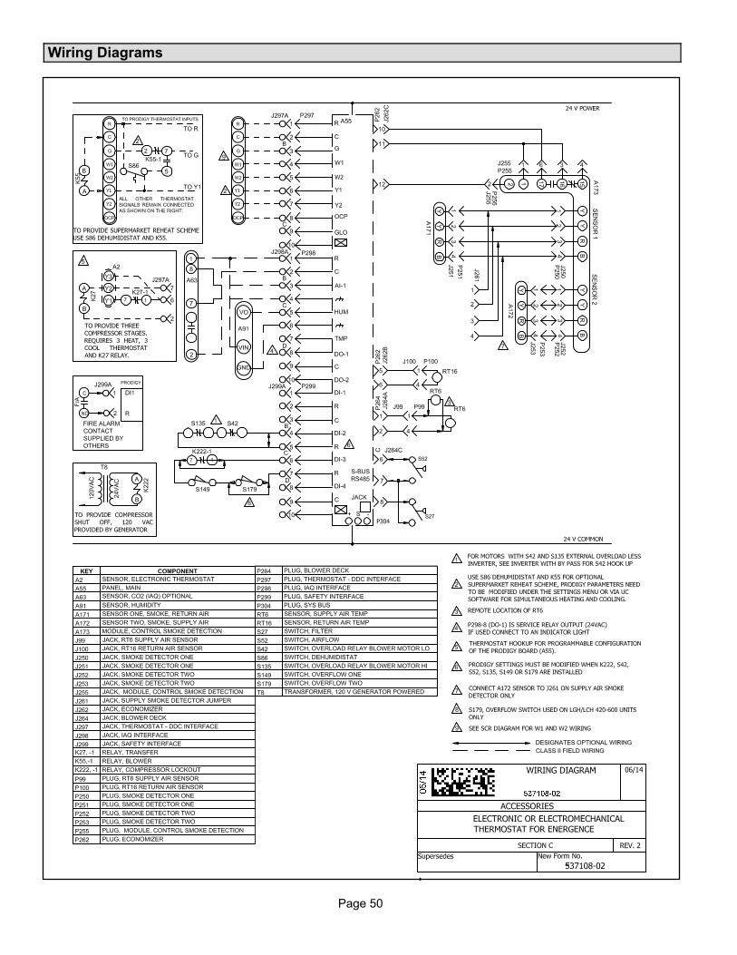
Page 50
Wiring Diagrams
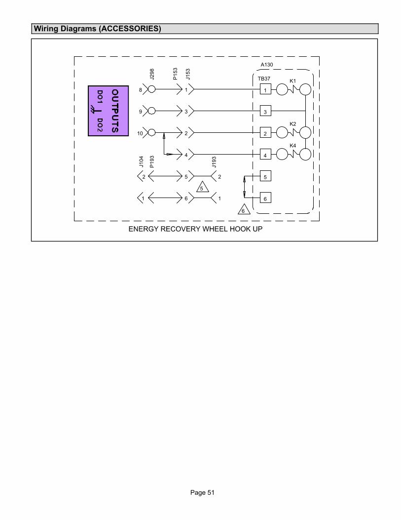
Page 51
Page 51
Wiring Diagrams (ACCESSORIES)
J298
8
9
10
P153
J153
1
3
2
4
5
6
P193
J104
2
1 1
J193
2
TB37
1
3
2
4
K1
K2
K4
5
6
A130
5
6

Page 52
Quick Start Guide
CAUTIONCheck rooftop unit electrical power for proper voltage and phasing. Check gas train components.
1. Turn on unit and dismiss alarm messages as necessary.
2. Follow SETUP > INSTALL menu to properly configure unit
3. Be sure unit is in normal operating mode as seen in display (COOLING, HEATING, IDLE, etc).
4. To verify operation use SERVICE > TEST menu.
Control Mode Menu Setup Needed Tips
THERMOSTAT (Factory set for 2-stage thermostat) � Check LEDs for signals.
BACnetSETUP > NETWORK INTEGRATION >NETWORK TYPE = BACNET
� Setup information to be verified with integrator.
� Follow wiring instructions including network
termination
� Remember to set MAC address 0-127
� Expert level BACnet service manual available.
LonTalkSETUP > NETWORK INTEGRATION >NETWORK TYPE = LONTALK
� Setup information to be verified with integrator.
� Follow wiring instructions including network
termination
� XIF file available. Neuron ID on sticker.
� Expert level LonTalk service manual available.
L ConnectionSETUP > NETWORK INTEGRATION >NETWORK TYPE = L-CONNECTION
� Follow wiring instructions including network
termination
� Comfort Sensors are 24 VAC polarity sensitive.
� All network devices need to be correctly
addressed
Damper SETUP > TEST & BALANCE > DAMPER
� Verify damper minimum positions
� Refer to Economizer section of manual for more
detail
Local ModeSETUP > NETWORK INTEGRATION >NETWORK TYPE = RTU STANDALONE
� Give unit time to start-up.
� Humidity control requires sensor or error code
7649
DehumidifierSETTINGS > RTU OPTIONS >DEHUMIDIFIER
� Three possible connections, LOCAL SENSOR,
NETWORK SENSOR and REHEAT DI4.
� Analog sensor wiring is polarity sensitive
BlowerChange motor torque; see SETUP > TEST & BALANCE > BLOWER
� Final motor CFM should be set by Test and
Balance technician
� Blower charts are located in the unit installation
instruction.
For Lennox Service Support 1-800-4LENNOX. For Lennox Commercial website, go to www.lennoxcommercial.com.

Page 53
Page 53
INDEXA
Abbreviations, Page 34
Auto Cycles, Page 22
B
BACnet Occupancy Points, Page 22
Blower Operation Description, Page 22
Blower Operation Modes, On, Cycles, Cycles w/Stir,Page 23
Blower Operation Schedule, Page 23
Blower Operation with Effective Occupancy, Page 22
C
Comp Load Shedding, Page 5
Configuration ID 1Advanced Air Flow Control System, Page 8Blower Variable Frequency Drive Bypass, Page 8Economizer, Page 8Humiditrol, Page 8Network Module, Page 8Outdoor Air CFM Control, Page 8Power Exhaust, Page 8Power Exhaust Control, Page 8
Configuration ID 2, Page 9Air Flow Proving Switch (S52), Page 9Dirty Filter Switch (S27), Page 9Electric Heat, Page 9Load Shedding, Page 9Motor Overload Switch (S42), Page 9Overflow Switch (S149/S179), Page 9Phase / Voltage Detection, Page 9Ultra Violet Lamp, Page 9Zone Bypass Damper, Page 9
D
Damper Operation during Free Cooling, Page 25
Demand Control Ventilation , Page 29
E
Economizer, Page 24
Economizer Checkout , Page 27
Enthalpy Sensor Output Current Honeywell C7400, Page26
Enthalpy Set Point, Page 25
F
Firmware Update, Page 6
Free Cooling Compressor Lockout Mode and LowAmbient Set Point, Page 25
Free Cooling Damper Maximum Position, Page 27
H
Heartbeat, Page 3
Humidity Sensor, Page 2
Humidity Sensor Connection, Page 2
L
LED, Page 2
Level 1 Menu Options, Page 10
Lontalk Occupancy Points, Page 23
M
MenuData, Page 11
Advanced Status, Page 13Factory, Page 12History, Page 11In/Outputs, Page 11Network, Page 12Runtimes, Page 13
ServiceOffline, Page 17Replace, Page 16Report, Page 17Software Update, Page 17Test, Page 16
SettingsControl, Page 18General, Page 21Install, Page 20RTU Options, Page 19
SetupInstall, Page 14Network Integration, Page 14Test and Balance, Page 15
Mode Messages, Page 5
Model NumberBlower Type, Page 7Design Sequence, Page 7Efficiency, Page 7Factory Electric or Gas Heat, Page 7Refrigerant, Page 7Tonnage, Page 7Type, Page 7Voltage, Page 7

Page 54
Motorized Outdoor Air Damper, Page 27
N
Networking Serial Communications (RS-485), Page 33
O
On-Continuous 1, Page 22
On-Continuous 2, Page 22
On-Continuous 3, Page 22
Outdoor Air Suitable for Free Cooling, Page 25
P
Profiles, Page 6
R
RJ-11, Page 2
S
S-BUS, Page 2
System Status Display, Page 4
T
Thermostat Connection, Page 2
Title 24, Page 22
U
Unit Operations, Page 4
USB Flash Drive Usage, Page 2
USB Service Reports, Page 35


Page 1
INSTALLATION INSTRUCTIONS FOR ECONOMIZERS AND OUTDOOR AIR HOODSUSED WITH LG/LC 036, 048, 060, 072 UNITS
Litho U.S.A. 507225-018/2014Supersedes 7/2014
2014 E1ECON ECONOMIZERS
ECONOMIZERS
Note - Disregard economizer installation section when
dampers are factory-installed.
Shipping and Packing List
Package 1 of 1 contains:
1- Economizer damper assemblyA
1- GEDB (gravity exhaust / barometric relief damper)
assembly
1- Exhaust hood kit containing:
1-Exhaust hood topA
2-Hood sidesC
1-GED sealC
1- Outdoor air hood kit containing:
1-Outdoor air hood topA
2-Hood sidesD
1- BirdscreenD
2- Bird screen bracketsD
1- Bag assembly containing:
#10-32 X 1/2 Self-drilling screws
#10-16 X 5/8 Self-drilling screwsAAlready in place when economizer is factory-installed.BOptional GED already in place when economizer is
factory-installed; shipped separately when PEF is
factory-installed.CShipped under the exhaust air cover when economizer is
factory-installed.DShipped in the blower section when economizer is
factory-installed.
Package 1 of 1 (ordered separately) contains:
Used in horizontal airflow applications only
1- Return air cover
Order Of Installation:
Return air cover (horizontal airflow)
Economizer
Mixed air sensor (R1)
Remove GED (horizontal airflow and PEF options)
Optional OA/RA sensors
Power exhaust fans
GED seal in unit (PEF option)
GED in lower hood (horizontal and PEF options)
RA Transition (horizontal airflow)
RA duct (horizontal airflow)
Lower outdoor air hood
Upper outdoor air hood
WARNINGImproper installation, adjustment, alteration, serviceor maintenance can cause property damage, personal injury or loss of life. Installation and service mustbe performed by a qualified installer, service agencyor the gas supplier
CAUTIONDanger of sharp metallic edges. Can cause injury.Take care when servicing unit to avoid accidentalcontact with sharp edges.
Application
The E1ECON economizer is used with LG/LC units in
downflow and horizontal air discharge applications. See
table 1. See table 2 for the optional gravity exhaust kit.
The economizer uses outdoor air for free cooling when
temperature and/or humidity is suitable. LG/LC units are
equipped with the following factory-installed, CEC Title
24 approved sensors:
RT17 - Outside Air Temperature
RT16 - Return Air Temperature
RT6 - Discharge Air Temperature
See figure 13 in the Start-Up section for sensor location.
Optional field-provided sensors may be used instead of
unit sensors to determine whether outdoor air is suitable
for free cooling. Refer to table 3 in the Start-Up section.
TABLE 1
Economizer
Econ Type Part No.*
Standard 90W59 609258-01
High Performance 10U54 609258-05
*Kits include GED and hoods.
TABLE 2
Gravity Exhaust Kit
Description Part No.
*Used when power exhaust is eitherfield- installed or not installed.
74W38 606568-01
Used when power exhaust is factory-installed.
72W89 605993-01
*Kits include hoods.

Page 2
Install Economizer - Downflow
1- Open unit end panel and filter access panel. See figure
1. When gravity or power exhaust are field-installed,
remove and discard the lower panel.
2- Remove and retain sensors from mounting bracket.
See figure 2. Remove mounting bracket and discard.
3- Install damper assembly through end of unit. Fit
opening in bottom of damper assembly over the return
air opening. See figure 3.
4- Install retained sensors in the side of the economizer.
See figure 3.
5- Disconnect jumper plug P3 from unit jack J3.
Connect economizer plug P4 to unit jack J3 as shown
in figure 4.
UNIT
Lower panel provided only when economizer isfactory-installed without gravity or power exhaust.
Remove and discard when field-installingGED and/or PEF.
FIGURE 1
FILTER ACCESSPANEL
UNIT ENDPANEL
FIGURE 2
REMOVE SENSORS AND BRACKET
SENSORBRACKET
A2 SENSOR(UNITS WITH DDC
CONTROL)
RT16SENSOR
SMOKE DETECTOR(WHEN EQUIPPED)

Page 3
ECONOMIZER INSTALLATION
ECONOMIZER(STANDARD
ECONOMIZERSHOWN)
FIGURE 3
RETURN AIROPENING
UNIT
B7DAMPER MOTOR
A2 SENSOR(UNITS WITH DDC
CONTROL)
RT16SENSOR
SMOKE DETECTOR(WHEN EQUIPPED)
FIGURE 4
CONNECT ECONOMIZER PLUG P4TO UNIT JACK J3
FILTERSECTION
EVAPORATORCOIL
J3
P4
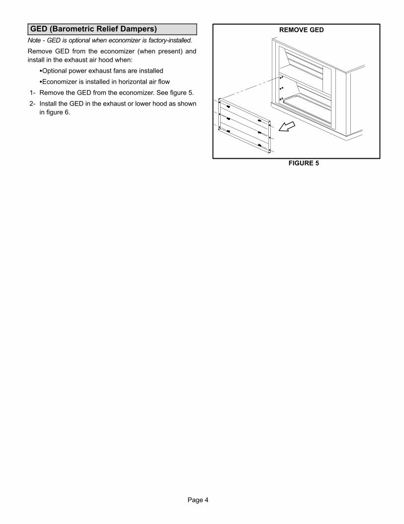
Page 4
GED (Barometric Relief Dampers)
Note - GED is optional when economizer is factory-installed.
Remove GED from the economizer (when present) and
install in the exhaust air hood when:
�Optional power exhaust fans are installed
�Economizer is installed in horizontal air flow
1- Remove the GED from the economizer. See figure 5.
2- Install the GED in the exhaust or lower hood as shown
in figure 6.
REMOVE GED
FIGURE 5
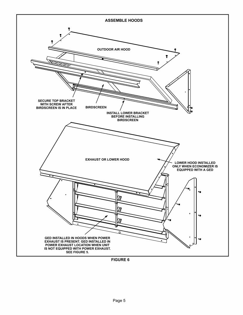
Page 5
FIGURE 6
ASSEMBLE HOODS
INSTALL LOWER BRACKETBEFORE INSTALLING
BIRDSCREEN
BIRDSCREEN
SECURE TOP BRACKETWITH SCREW AFTER
BIRDSCREEN IS IN PLACE
GED INSTALLED IN HOODS WHEN POWEREXHAUST IS PRESENT. GED INSTALLED INPOWER EXHAUST LOCATION WHEN UNIT
IS NOT EQUIPPED WITH POWER EXHAUST.SEE FIGURE 5.
OUTDOOR AIR HOOD
EXHAUST OR LOWER HOODLOWER HOOD INSTALLED
ONLY WHEN ECONOMIZER ISEQUIPPED WITH A GED
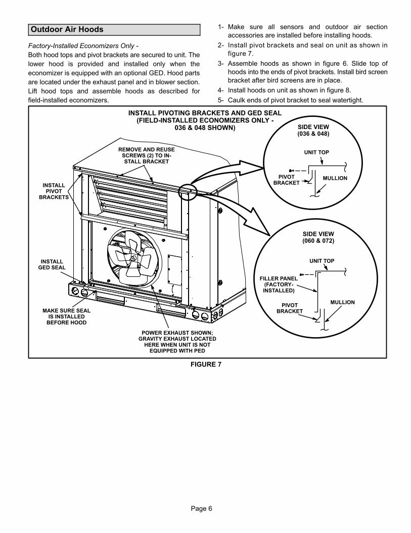
Page 6
Outdoor Air Hoods
Factory-Installed Economizers Only -
Both hood tops and pivot brackets are secured to unit. The
lower hood is provided and installed only when the
economizer is equipped with an optional GED. Hood parts
are located under the exhaust panel and in blower section.
Lift hood tops and assemble hoods as described for
field-installed economizers.
1- Make sure all sensors and outdoor air section
accessories are installed before installing hoods.
2- Install pivot brackets and seal on unit as shown in
figure 7.
3- Assemble hoods as shown in figure 6. Slide top of
hoods into the ends of pivot brackets. Install bird screen
bracket after bird screens are in place.
4- Install hoods on unit as shown in figure 8.
5- Caulk ends of pivot bracket to seal watertight.
FIGURE 7
PIVOTBRACKET
MULLION
REMOVE AND REUSESCREWS (2) TO INSTALL BRACKET
INSTALL PIVOTING BRACKETS AND GED SEAL(FIELD-INSTALLED ECONOMIZERS ONLY -
036 & 048 SHOWN)
INSTALLPIVOT
BRACKETS
INSTALLGED SEAL
MAKE SURE SEALIS INSTALLED
BEFORE HOOD
UNIT TOP
SIDE VIEW(036 & 048)
POWER EXHAUST SHOWN;GRAVITY EXHAUST LOCATED
HERE WHEN UNIT IS NOTEQUIPPED WITH PED
PIVOTBRACKET
MULLION
UNIT TOP
SIDE VIEW(060 & 072)
FILLER PANEL(FACTORY-INSTALLED)
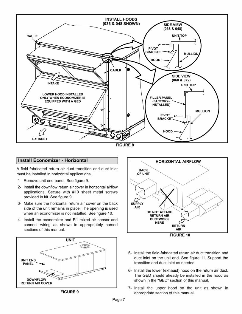
Page 7
FIGURE 8
INSTALL HOODS(036 & 048 SHOWN)
INTAKE
EXHAUST
PIVOTBRACKET
MULLION
UNIT TOP
SIDE VIEW(036 & 048)
HOOD
CAULK
CAULK
LOWER HOOD INSTALLEDONLY WHEN ECONOMIZER IS
EQUIPPED WITH A GED
PIVOTBRACKET
MULLION
UNIT TOP
SIDE VIEW(060 & 072)
FILLER PANEL(FACTORY-INSTALLED)
HOOD
Install Economizer - Horizontal
A field fabricated return air duct transition and duct inlet
must be installed in horizontal applications.
1- Remove unit end panel. See figure 9.
2- Install the downflow return air cover in horizontal airflow
applications. Secure with #10 sheet metal screws
provided in kit. See figure 9.
3- Make sure the horizontal return air cover on the back
side of the unit remains in place. The opening is used
when an economizer is not installed. See figure 10.
4- Install the economizer and R1 mixed air sensor and
connect wiring as shown in appropriately named
sections of this manual.
FIGURE 9
DOWNFLOWRETURN AIR COVER
UNIT
UNIT ENDPANEL
HORIZONTAL AIRFLOW
BACKOF UNIT
DO NOT ATTACHRETURN AIRDUCTWORK
HERE
SUPPLYAIR
RETURNAIR
FIGURE 10
5- Install the field-fabricated return air duct transition and
duct inlet on the unit end. See figure 11. Support the
transition and duct inlet as needed.
6- Install the lower (exhaust) hood on the return air duct.
The GED should already be installed in the hood as
shown in the “GED” section of this manual.
7- Install the upper hood on the unit as shown in
appropriate section of this manual.

Page 8
RETURN AIRDUCT INLET
HORIZONTALSUPPLY AIR
OPENING
SUPPLYAIR DUCT
RETURNAIR DUCT
EXHAUST HOOD
RETURN AIRDUCT TRANSITION
OUTDOORAIR HOOD
TOP VIEW
BACK VIEW
EXHAUSTAIR
This opening notused in
HorizontalApplications
with Economizer
Baro
metr
ic R
elie
f H
ood
and D
am
pers
HORIZON-TAL
RETURNAIR
OPENING
RETURN AIRDUCT TRANSITION
ECONOMIZERDAMPERS
RETURNAIR INLETSUPPLY
AIR OUTLET
FIGURE 11
TYPICAL HORIZONTAL APPLICATION
Economizer Start-Up - M2 Unit Controller
The unit will be equipped with either an M2 or M3 Unit
Controller. M2 or M3 will be printed on the bottom of the Unit
Controller near the SBUS connector. Use the appropriate
start-up section in this manual and refer to the Unit
Controller provided with the rooftop unit. Application
manuals are available for both Unit Controllers.
The economizer is controlled by the Unit Controller which is
located in the unit control panel. A detailed menu layout can be
found in the Unit Controller manual provided with each unit.
A-Field-Installed Economizer
The Unit Controller must be set to identify an economizer
has been installed.
1- Use the Unit Controller keypad to enter the following menu:
Setting / Install / Damper
2- Use the up/down arrows to display ECON and press the
SELECT button (!SET! will display).
3- Press the left arrow returning up the menu path until the
Unit Controller resets and saves the change.
The Unit Controller will now operate the economizer.
B-Free Cooling Mode and Setpoint
On start-up, the economizer mode defaults to TEMP
OFFSET. In this mode, free cooling is energized when the
outdoor air temperature (RT17) is less than return air
temperature (RT16) by at least the offset value. The default
offset value is 10°F. Use the following menu path on the Unit
Controller to adjust the free cooling mode or setpoint. See
figure 13 for sensor location.
Settings / Setpoints / Damper / Economizer Mode
Refer to table 3 and figure 12 for additional free cooling
modes and setpoints. The Unit Controller has a restricted
range of input values for each mode as shown in table 3.
Note - An energy management system may be used to
provide the outdoor air suitable (OAS) signal via network
connection. The free cooling mode must be set to one of the
TEMP modes to allow this function.

Page 9
C-California Title 24 Compliance
For California Title 24 compliance, adjust the free cooling
setpoint based on:
-The climate zone where the unit is installed. See table 4.
-The setpoint requirement published by the California
Energy Commission. See Section 140.4 - Prescriptive
Requirements for Space Conditioning Systems of the
2013 Building Energy Efficiency Standards.
Note - Values in the referenced standard will supersede
values listed in table 4.
FIGURE 12
PARTIAL VIEW OF UNIT CONTROLLER MENU
OFFSET
DAMPER
SETPOINTS
ECONOMIZERMODE
TEMPCONTROL
XXºF ! SET !
GLOBAL
Usearrows
tomove
Usearrows
tomove
XX.XMA
! SET !
OATSTPT
XXºF ! SET !
ENTHCONTROL
! SET !DIFF OFFSET
XX.XMA
! SET !ODESTPT
SUPPLY AIR STPT XX.XºF [44.9 TO 65.3ºF] ! SET !
MIN OCP BLOWER LOW XXX% [0 TO 100%} ! SET !
MIN OCP BLOWER HIGH XXX% [0 TO 100%] ! SET !
FIGURE 13
SENSOR LOCATION
RT17OUTDOOR AIR SENSOR(SECURED TO INSIDE OF
CORNER MULLION)
RT16RETURN
AIR SENSOR RT6DISCHARGEAIR SENSOR

Page 10
TABLE 3ECONOMIZER MODES AND SETPOINT
FreeCoolingMode
FreeCoolingSetpoint
Field-ProvidedSensors
Dampers will modulate to 55°F discharge air (RT6) when outdoorair is suitable:
PermittedInputs
TEMP OFFSET None NeededOutdoor air temperature (RT17) is less than return air temperature (RT16) by atleast the OFFSET value. 0-40°F
TEMP OAT STPT None Needed Outdoor air temperature (RT17) is less than the OAT STPT value. 41-75°F
Remote RemoteEnergyManagementSystem**
Either of the TEMP modes can be used when a network OAS signal is provided byan energy management or building control system, via BACnet, LonTalk, or L Connection. The network can command OAS, NOT OAS, or AUTO. AUTO returns tolocal control of OAS, which is the selected TEMP mode.
NA
ENTH DIFF OFFSET (Two) C7400Outdoor air enthalpy* (A7) is less than return air enthalpy (A62) by at least the OFFSET value.
0mA-4mA
ENTH ODE STPT C7400 Outdoor air enthalpy (A7) is less than free cooling setpoint. 12-19mA
GLOBAL GLOBAL24VAC InputSignal
Global input is energized by (P297-9). This setting is also used for outdoor air damper applications. Global input also brings on the blower. (This mode is NOT usedwhen OAS signal is provided via network connection. GLO is only used when a24VAC signal is used to energize the P297-9 GLO input.)
NA
*Enthalpy includes effects of both temperature and humidity.
**Energy management system smay require additional field-provided sensors; refer to manufacturer's instructions.
TABLE 4
FREE COOLING SETPOINT
Climate ZoneSetpoint
(Single Sensible)Setpoint
(Differential Sensible)
1, 3, 5, 11-16 75�F 0�F
2, 4, 10 73�F 2�F
6, 8, 9 71�F 4�F
7 69�F 6�F
D-Setting Free Cooling Setpoint in Enthalpy Mode
Free Cooling Setpoint - ODE STPT
The enthalpy sensor (A7) provides a milliamp signal to the
Unit Controller based on outdoor air temperature and
humidity. See table 5. To set a free cooling setpoint of 73°F
at 50% relative humidity, enter “12” at the ODE STPT menu
prompt. The Unit Controller will allow dampers to modulate
open at approximately 73°F. If the space temperature is too
warm, change the ODE STPT to “13.6” and the Unit
Controller will allow dampers to modulate open at
approximately 70°F.
TABLE 5
FREE COOLING SETPOINT - ODE STPT MODE
Enthalpy Setpoint °F (°C)* Menu Entry - mA Counts
73 (23) 12.0 150
70 (21) 13.6 173
67 (19) 15.5 199
63 (17) 17.6 224
*Approximate temperature at 50% relative humidity.
Free Cooling Differential Enthalpy - DIFF OFFSET
The Unit Controller allows damper modulation when
outdoor air is lower than return air by a differential or offset
temperature and humidity range. To set an offset range of
7°F at a constant relative humidity, enter “4” at the DIFF
OFFSET menu prompt. If return air is 76°F, the Unit
Controller will allow damper to modulate open at
approximately 69°F outdoor air. See table 6. If the space
temperature is too cool or dry, change the DIFF OFFSET to
“3” and the Unit Controller will allow dampers to modulate
open at approximately 71°F outdoor air.
TABLE 6
FREE COOLING SETPOINT - DIFF OFFSET MODE
*TemperatureOffset °F
**Relative Humidity Offset %
Menu EntrymA
Counts
2 6 1 13
3.5 12 2 26
5.3 18 3 39
7 24 4 53
*At a constant relative humidity. **At a constant temperature.
E-Damper Minimum Position Setting
Use the menu path in figure 12 to set the minimum % open
damper position when outdoor air is not suitable for free
cooling. The minimum setpoint range is 0% open
(dampers closed) to 100% (dampers fully open). On units
equipped with a ventilation control board, refer to the VCB
Start-Up section in the installation instructions provided
with each unit.

Page 11
TABLE 7
FREE COOLING OPTIONS
Config ID1POS 2)
Unit ControllerInput (Mode)
M3 Display(Free Cooling Options)
DefaultSetting
RangeSetting
Outdoor air is suitable for free cooling when:
TDifferential
Sensible Sensor(default mode)
ECONOMIZER TEMPECON TYPE =TEMPERATUREOFFSET
10°F 0°F - 40°FOutdoor air temperature (RT17) is less than return airtemperature (RT16) by at least the offset value.
TSingle Sensible
Sensor
ECONOMIZER TEMPECON TYPE =TEMPERATURESETPOINT
75°F 40 F - 75 FOutdoor air temperature (RT17) is less than the Outdoor Air Temperature set point value.
T Network OAS
ECONOMIZER TEMPECON TYPE = TEMPERATURE OFFSET orSETPOINT
NotApplicable
Not Applicable
Either of the TEMP modes (set point or offset) can beused when a network OAS signal is provided by anenergy management or building control system, viaBACnet, LonTalk, or L Connection. The network cancommand OAS, NOT OAS, or AUTO. AUTO returns tolocal control of OAS, which is the selected TEMP mode.
SSingle Enthalpy*
Sensor
ECONOMIZERENTHALPY SETPOINT =12.0 MA
12.0 mA 10mA - 19 mAOutdoor air enthalpy (A7) is less than enthalpy set pointparameter.
DDifferential Enthalpy* Sensor
ECONOMIZERENTHALPY OFFSET =1.0 MA
1.0 mA 1 mA - 5 mAOutdoor air enthalpy* (A7) is less than return air enthalpy (A62) by at least the OFFSET value.
G Global
Mode and setpoint are notset by Unit Controller.Menu advances to:FREE COOLINGSUPPLY AIR SETPOINT= 55°F
NotApplicable
Not Applicable
Global input is energized by (P297-9). This setting isalso used for outdoor air damper applications. Globalinput also brings on the blower. (This mode is NOTused when OAS signal is provided via network connection. GLO is only used when a 24VAC signal is used toenergize the P297-9 GLO input.)
*Enthalpy includes effects of both temperature and humidity.
Economizer Start-Up - M3 Unit Controller
The unit will be equipped with either an M2 or M3 Unit
Controller. M2 or M3 will be printed on the bottom of the Unit
Controller near the SBUS connector. Use the appropriate
start-up section in this manual and refer to the Unit Controller
provided with the rooftop unit. Application manuals are
available for both Unit Controllers.
The economizer is controlled by the Unit Controller which is
located on the unit control panel. A detailed menu layout can be
found in the Unit Controller manual provided with each unit.
A-Field-Installed Economizer
The Unit Controller must be set to identify an economizer
has been installed. The configuration ID will also identify
which sensor inputs the Unit Controller will use to determine
the free cooling mode. See figure 13 for sensor location.
1- Use the Unit Controller keypad to enter the following menu:
MAIN MENU > SETUP > INSTALL
2- Press SAVE until CONFIGURATION ID 1 appears.
Change the second character in the configuration ID to
identify the type of input used to determine economizer
free cooling setpoint. See table 7.
3- Press SAVE. The Unit Controller is now set up to
operate the economizer.
4- Press the MAIN MENU button, then the BACK button,
to display the status screen.
B-Adjust Free Cooling Discharge Air Setpoint
When outdoor air is suitable for free cooling, dampers will
modulate to maintain a discharge air temperature of 55ºF
default (adjustable range 45º-67ºF). Refer to RT6
discharge air sensor location shown in figure 13.

Page 12
C-Free Cooling Modes
The Unit Controller automatically sets the free cooling mode
when the configuration ID is entered. The temperature
setpoint mode is the only exception.
1- Use the following menu path on the Unit Controller to
enter the temperature setpoint mode.
MAIN MENU > SETTINGS > RTU OPTIONS > DAMPER >
ECONOMIZER TEMP ECON TYPE =
TEMPERATURE OFFSET (default)
2- Use the “Adjust and set values” arrows on the keypad
to select TEMPERATURE SETPT.
3- Press SAVE.
Note - Network OAS signal and California Title 24
Compliance options use either TEMPERATURE OFFSET
or TEMPERATURE SETPT mode.
D-Adjust Outdoor Air Free Cooling Setpoint
Note - Configuration ID 1 must be set to the appropriate
mode before adjusting the free cooling setpoint. See table 7
Temperature Offset or Temperature Setpoint Mode
1- After the free cooling mode is saved, if default setpoint
value needs to change, enter the new number and
press SAVE.
2- For California Title 24 compliance, adjust the free
cooling setpoint based on:
-The climate zone where the unit is installed. See table 4.
-The setpoint requirement published by the California
Energy Commission. See Section 140.4 - Prescriptive
Requirements for Space Conditioning Systems of the
2013 Building Energy Efficiency Standards.
Note - Values in the referenced standard will supersede
values listed in table 4.
3- When a network OAS signal is provided by a building
control system, refer to control system literature to
adjust free cooling setpoint.
Enthalpy Setpoint
The enthalpy sensor (A7) provides a milliamp signal to the
Unit Controller based on outdoor air temperature and
humidity. Use the following menu to change the setpoint:
MAIN MENU > SETTINGS > RTU OPTIONS > DAMPER
> ECONOMIZER ENTHALPY SETPOINT = 12.0 MA
Refer to table 5. At 12.0mA, the Unit Controller will allow
dampers to modulate open at approximately 73°F. If the
space temperature is too warm or humid, change the
ECONOMIZER ENTHALPY SETPOINT to “13.6MA” and
the Unit Controller will allow dampers to modulate open at
approximately 70°F.
Enthalpy Offset
The Unit Controller allows damper modulation when
outdoor air is lower than return air by a differential or offset
temperature and humidity range. Use the following menu to
change the setpoint:
MAIN MENU > SETTINGS > RTU OPTIONS > DAMPER
> ECONOMIZER ENTHALPY OFFSET = 1.0 MA
Refer to table 6. At 1.0mA, the Unit Controller will allow
dampers to modulate open when outdoor air is lower than
return air by approximately a 2°F offset. If return air is 76°F,
the Unit Controller will allow dampers to modulate open at
approximately 74°F. If the space temperature is to warm or
humid, change the ECONOMIZER ENTHALPY SETPOINT
to 2.0mA or an offset of 3.5°F. The Unit Controller will allow
dampers to modulate open at approximately 72.5°F.
E-Damper Minimum Position Setting
Use the menu path in table 8 to set the MIN DAMPER
POSITION BLOWER ON HIGH when outdoor air is not
suitable for free cooling. The minimum setpoint range is 0%
open (dampers closed) to 100% (dampers fully open). On
units with staged supply air blowers, also set the MIN
DAMPER POSITION BLOWER ON LOW.
TABLE 8
DAMPER OPTIONS
Level 2 Level 3 Level 4 Level 5
RTUOP
TIONDAMPER
ECONOMIZER ENTHALPY OFFSET = 12.0 MA
ECONOMIZER ENTHALPY SETPOINT = 1.0 MA
ECONOMIZER TEMP ECON TYPE = TEMPERATUREOFFSET OR TEMPERATURE SETPT
ECONOMIZER OAT SETPOINT = XX.X F
FREE COOLING SUPPLY AIR SETPOINT = 55°F
MIN DAMPER POSITION BLOWER ON HIGH = X.X %
MIN DAMPER POSITION BLOWER ON LOW = X.X %
Note - Menu options vary depending on hardware configuration.
Note - Use the “Adjust and set values” arrows to scroll up or down for
selection options.

12/09 506217−01
�������� ����������Page 1
CONTROLSKITS AND ACCESSORIES Litho U.S.A.
�2009 Lennox Industries Inc.Dallas, Texas, USA
506217−01 12/09Supersedes 505080M
LonTalk® MODULE KIT
INSTALLATION INSTRUCTIONS FOR LONTALK MODULE KIT(11W28) USED WITH LG/LC/LH & SG/SC AND ENERGENCE� ROOFTOP UNITS
Table of Contents
Application 2. . . . . . . . . . . . . . . . . . . . . . . . . . . . . . . . . . . Installation 2. . . . . . . . . . . . . . . . . . . . . . . . . . . . . . . . . . . . Configuring IMC / M2 Unit Controller 4. . . . . . . . . . . . Communications Check Out 5. . . . . . . . . . . . . . . . . . . . LonWorks Network Connection 6. . . . . . . . . . . . . . . . . . Network Cable 6. . . . . . . . . . . . . . . . . . . . . . . . . . . . . . . Network Limits 6. . . . . . . . . . . . . . . . . . . . . . . . . . . . . . . . Network Integration 7. . . . . . . . . . . . . . . . . . . . . . . . . . . . Data Update Rate 7. . . . . . . . . . . . . . . . . . . . . . . . . . . . . Start Up & Normal Unit Operation 7. . . . . . . . . . . . . . Zone Sensor Setpoints 7. . . . . . . . . . . . . . . . . . . . . . . . . Inputs to/Outputs from IMC / M2 Unit Controller 8. . . Alarm Codes 8. . . . . . . . . . . . . . . . . . . . . . . . . . . . . . . .
NOTE − Disregard shipping and packing list and installation
sections when module is factory−installed.
Shipping and Packing List
Package 1 of 1 contains:
1− LonTalk module
4− #6 − 32 X 7/8" Screws
1− Mounting plate (used on 090−300S units only)
2− #10 − 16 X 5/8" Sheet metal screws (used on
090−300S units only)
1− 3−ft. length SYSBUS cable
1− 3 ft. length thermostat wire
1− Wiring diagram
Technical Assistance
For assistance contact Lennox Technical Support at800−453−6669.
Version Required
This module requires a rooftop unit IMC M1−7 (version 5.02or higher), M1−8, or M2 Unit Controller. An IMC upgrade kit
is available for earlier M1−7 versions. M1−6 and earlier IMCversions cannot be upgraded for use with the LonTalkmodule. M1−8 displays version when powered up in thescrolling text (may need to clear error codes). For display-ing version on M1−7:
1. Locate IMC board in compressor area. Refer to IMCmanual provided with rooftop unit.
2. Set the MODE DIP �UNIT TEST" and �RECALL"switches to �ON" (see figure 2).
3. The IMC LEDs will display the current IMC version(see figure 1).
4. Be certain to return the �UNIT TEST" and �RECALL"switches to �OFF" after viewing the version number.Communication to the IMC is interrupted while theseMODE DIP switches are �ON".
ON
UNIT TEST
RECALL
ECTO
TEMP
OPT2
SHIFT
MODESet the MODE DIP�UNIT TEST" and �RE-CALL" switches to �ON".
LED will display cur-rent software version.
Figure 1. Check M1−7, M1−8 Software Versionand Address
WARNINGImproper installation, adjustment, alteration, ser-vice or maintenance can cause property damage,personal injury or loss of life. Installation and ser-vice must be performed by a qualified installer orservice agency.
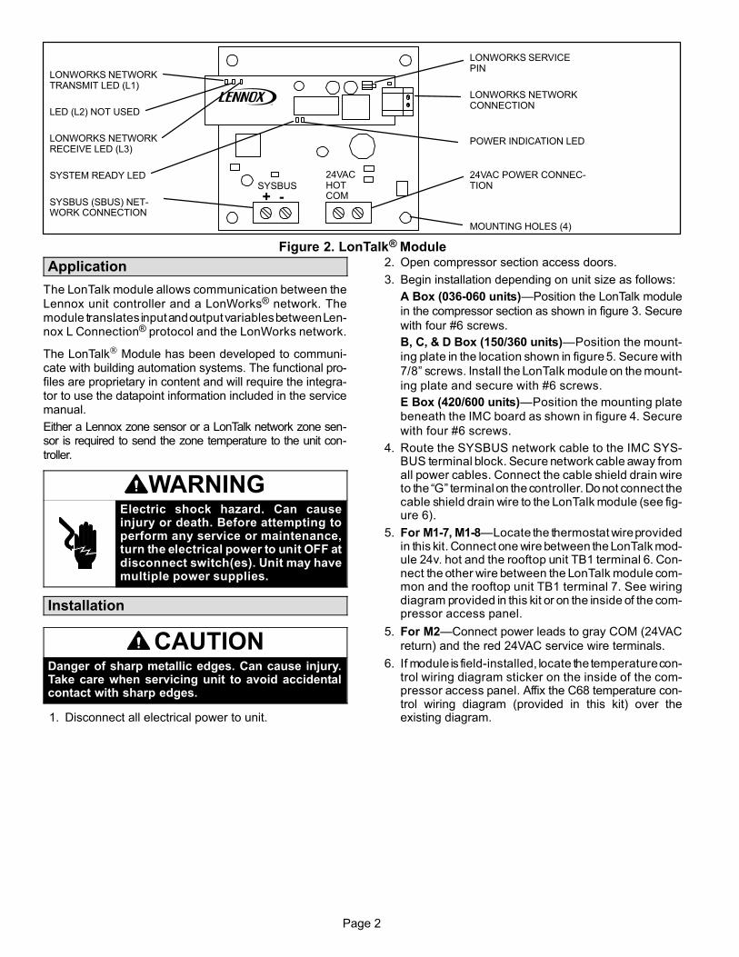
Page 2
LONWORKS SERVICEPIN
LONWORKS NETWORKCONNECTION
POWER INDICATION LED
24VAC POWER CONNEC-TION
MOUNTING HOLES (4)
SYSBUS
+ −
24VACHOTCOM
LONWORKS NETWORKTRANSMIT LED (L1)
LED (L2) NOT USED
LONWORKS NETWORKRECEIVE LED (L3)
SYSTEM READY LED
SYSBUS (SBUS) NET-WORK CONNECTION
Figure 2. LonTalk® Module
Application
The LonTalk module allows communication between the
Lennox unit controller and a LonWorks® network. Themodule translates input and output variables between Len-nox L Connection® protocol and the LonWorks network.
The LonTalk® Module has been developed to communi-cate with building automation systems. The functional pro-files are proprietary in content and will require the integra-tor to use the datapoint information included in the servicemanual.
Either a Lennox zone sensor or a LonTalk network zone sen-sor is required to send the zone temperature to the unit con-
troller.
WARNINGElectric shock hazard. Can causeinjury or death. Before attempting toperform any service or maintenance,turn the electrical power to unit OFF atdisconnect switch(es). Unit may havemultiple power supplies.
Installation
CAUTIONDanger of sharp metallic edges. Can cause injury.Take care when servicing unit to avoid accidentalcontact with sharp edges.
1. Disconnect all electrical power to unit.
2. Open compressor section access doors.
3. Begin installation depending on unit size as follows:
A Box (036−060 units)�Position the LonTalk module
in the compressor section as shown in figure 3. Secure
with four #6 screws.
B, C, & D Box (150/360 units)�Position the mount-
ing plate in the location shown in figure 5. Secure with
7/8" screws. Install the LonTalk module on the mount-
ing plate and secure with #6 screws.
E Box (420/600 units)�Position the mounting plate
beneath the IMC board as shown in figure 4. Secure
with four #6 screws.
4. Route the SYSBUS network cable to the IMC SYS-BUS terminal block. Secure network cable away fromall power cables. Connect the cable shield drain wireto the �G" terminal on the controller. Do not connect thecable shield drain wire to the LonTalk module (see fig-ure 6).
5. For M1−7, M1−8�Locate the thermostat wire providedin this kit. Connect one wire between the LonTalk mod-ule 24v. hot and the rooftop unit TB1 terminal 6. Con-nect the other wire between the LonTalk module com-mon and the rooftop unit TB1 terminal 7. See wiringdiagram provided in this kit or on the inside of the com-pressor access panel.
5. For M2�Connect power leads to gray COM (24VAC
return) and the red 24VAC service wire terminals.
6. If module is field−installed, locate the temperature con-trol wiring diagram sticker on the inside of the com-pressor access panel. Affix the C68 temperature con-trol wiring diagram (provided in this kit) over theexisting diagram.

Page 3
LONTALK MODULE
Figure 3. LonTalk Module (036−060 units, A box)
LONTALKMODULES−Class − E Box 420−600 A55
Figure 4. LonTalk Module (420/600 units, E Box)
ALIGN DIMPLES IN UNITMULLION WITH ENGAGINGHOLE IN MOUNTING PLATEFLANGE; SECURE WITH 5/8"SHEET METAL SCREW.
IMC / M2 BOARDHAT SECTION
MOUNTINGPLATE
IMC / M2BOARD
POSITION HOLE INMOUNTING PLATEFLANGE OVER IMCBOARD HAT SECTIONSCREW
LONTALKMODULE
Figure 5. LonTalk Module (150/360 units (B, C, & D box)
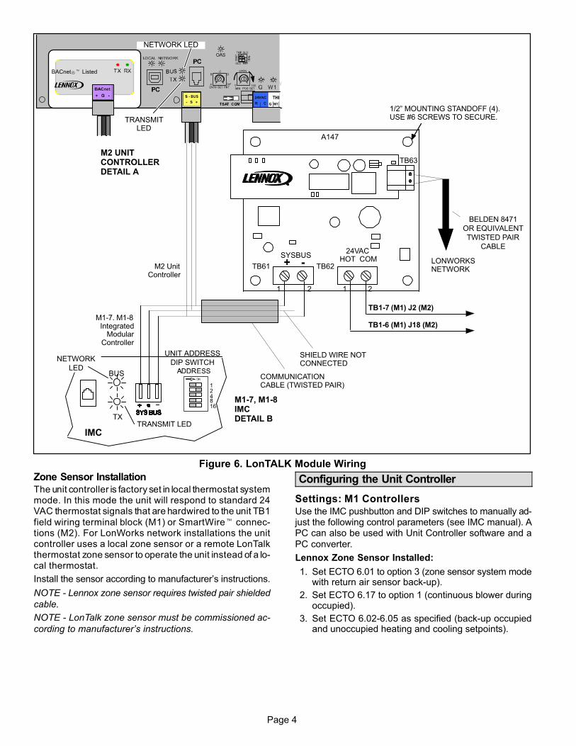
Page 4
BACnet�� Listed
TB1−7 (M1) J2 (M2)
LONWORKSNETWORK
COMMUNICATIONCABLE (TWISTED PAIR)
1/2" MOUNTING STANDOFF (4).USE #6 SCREWS TO SECURE.
TB61
1 2 1 2
TB63
TB62
A147
SYSBUS+ −
24VACHOT COM
BELDEN 8471
OR EQUIVALENT
TWISTED PAIR
CABLE
M1−7. M1−8Integrated
ModularController
M2 UNITCONTROLLERDETAIL A
TRANSMIT LEDTX
BUS
IMC
124816
UNIT ADDRESS
DIP SWITCH
NETWORK LED
TRANSMITLED
M1−7, M1−8IMCDETAIL B
NETWORK
LED
SHIELD WIRE NOTCONNECTED
M2 UnitController
TB1−6 (M1) J18 (M2)
Figure 6. LonTALK Module Wiring
Zone Sensor Installation
The unit controller is factory set in local thermostat systemmode. In this mode the unit will respond to standard 24VAC thermostat signals that are hardwired to the unit TB1
field wiring terminal block (M1) or SmartWire� connec-tions (M2). For LonWorks network installations the unitcontroller uses a local zone sensor or a remote LonTalkthermostat zone sensor to operate the unit instead of a lo-cal thermostat.
Install the sensor according to manufacturer’s instructions.
NOTE − Lennox zone sensor requires twisted pair shielded
cable.
NOTE − LonTalk zone sensor must be commissioned ac-
cording to manufacturer’s instructions.
Configuring the Unit Controller
Settings: M1 Controllers
Use the IMC pushbutton and DIP switches to manually ad-just the following control parameters (see IMC manual). APC can also be used with Unit Controller software and a
PC converter.
Lennox Zone Sensor Installed:
1. Set ECTO 6.01 to option 3 (zone sensor system modewith return air sensor back−up).
2. Set ECTO 6.17 to option 1 (continuous blower duringoccupied).
3. Set ECTO 6.02−6.05 as specified (back−up occupiedand unoccupied heating and cooling setpoints).
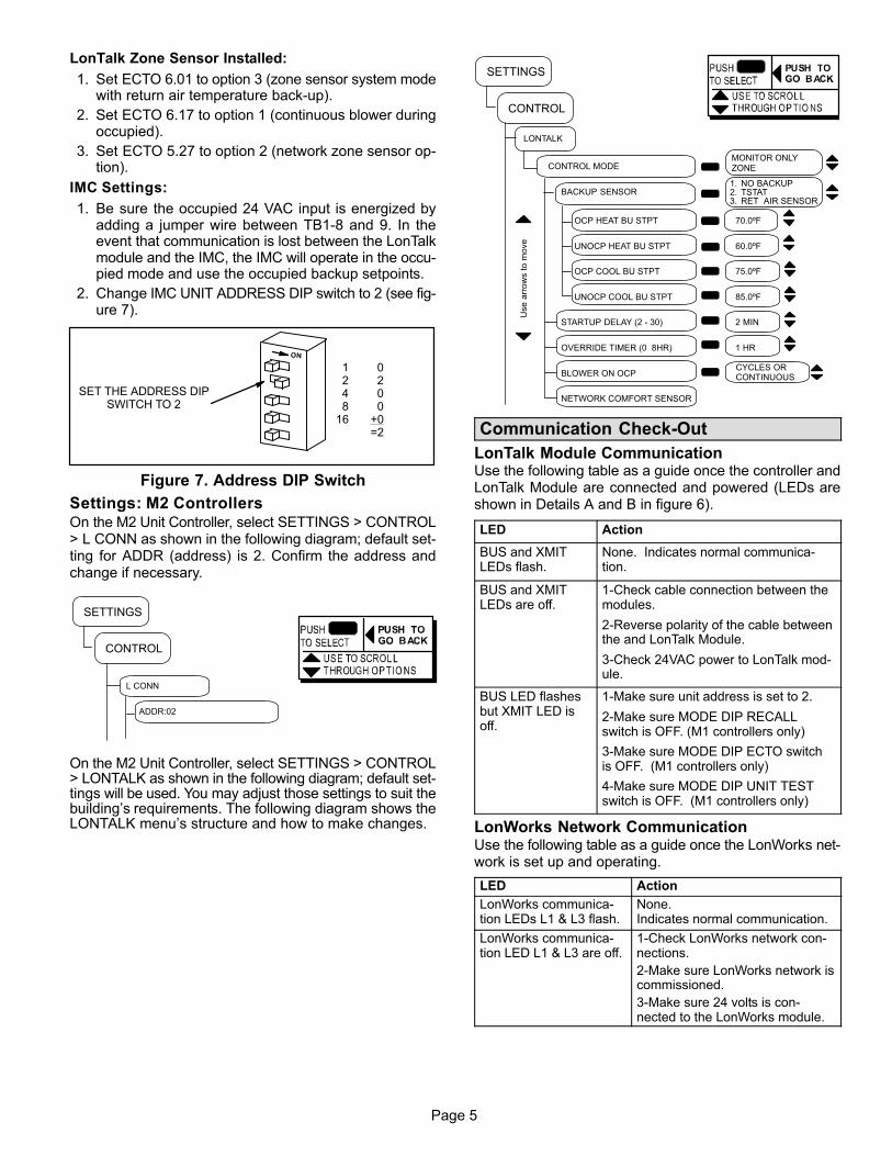
Page 5
LonTalk Zone Sensor Installed:
1. Set ECTO 6.01 to option 3 (zone sensor system modewith return air temperature back−up).
2. Set ECTO 6.17 to option 1 (continuous blower duringoccupied).
3. Set ECTO 5.27 to option 2 (network zone sensor op-tion).
IMC Settings:
1. Be sure the occupied 24 VAC input is energized byadding a jumper wire between TB1−8 and 9. In theevent that communication is lost between the LonTalkmodule and the IMC, the IMC will operate in the occu-pied mode and use the occupied backup setpoints.
2. Change IMC UNIT ADDRESS DIP switch to 2 (see fig-ure 7).
0200
+0=2
1248
16
SET THE ADDRESS DIPSWITCH TO 2
Figure 7. Address DIP Switch
Settings: M2 ControllersOn the M2 Unit Controller, select SETTINGS > CONTROL> L CONN as shown in the following diagram; default set-ting for ADDR (address) is 2. Confirm the address andchange if necessary.
L CONN
ADDR:02
CONTROL
SETTINGS
On the M2 Unit Controller, select SETTINGS > CONTROL> LONTALK as shown in the following diagram; default set-tings will be used. You may adjust those settings to suit thebuilding’s requirements. The following diagram shows theLONTALK menu’s structure and how to make changes.
Use
arr
ow
s t
o m
ove
CONTROL MODE
BACKUP SENSOR
OCP HEAT BU STPT 70.0ºF
UNOCP HEAT BU STPT 60.0ºF
OCP COOL BU STPT 75.0ºF
UNOCP COOL BU STPT 85.0ºF
STARTUP DELAY (2 − 30) 2 MIN
OVERRIDE TIMER (0 8HR) 1 HR
BLOWER ON OCP
NETWORK COMFORT SENSOR
LONTALK
CONTROL
CYCLES ORCONTINUOUS
1. NO BACKUP2. TSTAT 3. RET AIR SENSOR
MONITOR ONLYZONE
SETTINGS
Communication Check−Out
LonTalk Module CommunicationUse the following table as a guide once the controller andLonTalk Module are connected and powered (LEDs areshown in Details A and B in figure 6).
LED Action
BUS and XMITLEDs flash.
None. Indicates normal communica-tion.
BUS and XMITLEDs are off.
1−Check cable connection between themodules.
2−Reverse polarity of the cable betweenthe and LonTalk Module.
3−Check 24VAC power to LonTalk mod-ule.
BUS LED flashesbut XMIT LED isoff.
1−Make sure unit address is set to 2.
2−Make sure MODE DIP RECALLswitch is OFF. (M1 controllers only)
3−Make sure MODE DIP ECTO switchis OFF. (M1 controllers only)
4−Make sure MODE DIP UNIT TESTswitch is OFF. (M1 controllers only)
LonWorks Network CommunicationUse the following table as a guide once the LonWorks net-work is set up and operating.
LED Action
LonWorks communica-tion LEDs L1 & L3 flash.
None. Indicates normal communication.
LonWorks communica-tion LED L1 & L3 are off.
1−Check LonWorks network con-nections.
2−Make sure LonWorks network iscommissioned.
3−Make sure 24 volts is con-nected to the LonWorks module.
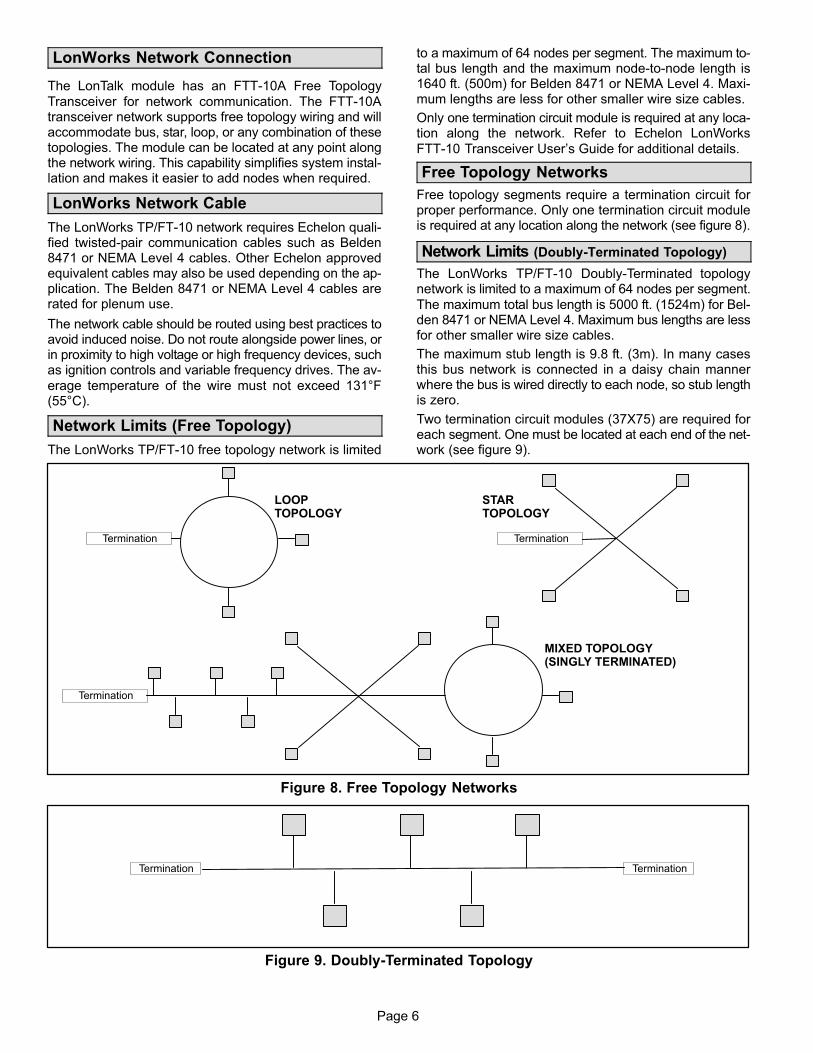
Page 6
LonWorks Network Connection
The LonTalk module has an FTT−10A Free Topology
Transceiver for network communication. The FTT−10Atransceiver network supports free topology wiring and willaccommodate bus, star, loop, or any combination of thesetopologies. The module can be located at any point alongthe network wiring. This capability simplifies system instal-lation and makes it easier to add nodes when required.
LonWorks Network Cable
The LonWorks TP/FT−10 network requires Echelon quali-fied twisted−pair communication cables such as Belden8471 or NEMA Level 4 cables. Other Echelon approvedequivalent cables may also be used depending on the ap-plication. The Belden 8471 or NEMA Level 4 cables arerated for plenum use.
The network cable should be routed using best practices toavoid induced noise. Do not route alongside power lines, orin proximity to high voltage or high frequency devices, suchas ignition controls and variable frequency drives. The av-
erage temperature of the wire must not exceed 131°F(55°C).
Network Limits (Free Topology)
The LonWorks TP/FT−10 free topology network is limited
to a maximum of 64 nodes per segment. The maximum to-tal bus length and the maximum node−to−node length is1640 ft. (500m) for Belden 8471 or NEMA Level 4. Maxi-mum lengths are less for other smaller wire size cables.
Only one termination circuit module is required at any loca-tion along the network. Refer to Echelon LonWorks
FTT−10 Transceiver User’s Guide for additional details.
Free Topology Networks
Free topology segments require a termination circuit forproper performance. Only one termination circuit moduleis required at any location along the network (see figure 8).
Network Limits (Doubly−Terminated Topology)
The LonWorks TP/FT−10 Doubly−Terminated topologynetwork is limited to a maximum of 64 nodes per segment.
The maximum total bus length is 5000 ft. (1524m) for Bel-den 8471 or NEMA Level 4. Maximum bus lengths are lessfor other smaller wire size cables.
The maximum stub length is 9.8 ft. (3m). In many casesthis bus network is connected in a daisy chain mannerwhere the bus is wired directly to each node, so stub lengthis zero.
Two termination circuit modules (37X75) are required foreach segment. One must be located at each end of the net-work (see figure 9).
LOOPTOPOLOGY
Termination
STARTOPOLOGY
MIXED TOPOLOGY(SINGLY TERMINATED)
Termination
Termination
Figure 8. Free Topology Networks
TerminationTermination
Figure 9. Doubly-Terminated Topology

Page 7
Network Integration
A network configurating tool such as LonMaker® is re-quired to commission the LonWorks network. Press theservice button on the LonTalk module to generate a servicemessage that contains the Neuron ID and all informationrequired to connect it to a system and to configure the
module.
Other commissioning methods may be used. The Neuronaddress is located on the Lontalk module.
An external Interface File (XIF) is available for configura-tion prior to installation.
The Lontalk module only supports service type ’acknowl-edged service’. For Tridium/JACE integration, this is
equivalent to ’critical binding’ on all variables.
Data Update Rate
If a LonTalk Zone Sensor is installed (ECTO 5.27 for M1controllers), the nviSpaceTemp point must be updated pe-riodically. If nviSpaceTemp is not updated for a period of 5
minutes, the IMC will go into the back−up modes describedin the �Lontalk Connection Failure" section:
It is highly recommended that the nviSpaceTemp variable,if it is used, be updated at least every 2 minutes.
Start−Up Operation (Before LonWorks Network is Commissioned)
Lennox Zone Sensor Installed�Prior to commission-ing, no LonWorks setpoint is available. The unit will be off.
Two minutes after power−up (ECTO 5.25), the IMC will op-erate the unit based on the IMC ECTO unoccupied backupsetpoints (heating = 60°F, cooling = 85°F) and current zonetemperature read by the Lennox zone sensor.
LonTalk Zone Sensor Installed�Prior to commission-ing, neither LonWorks setpoint nor sensor data are avail-able. The unit will be off.
Five minutes after power−up, the controller will operate theunit based on the unoccupied backup setpoints (heating =60°F, cooling = 85°F) and the current zone temperatureread by an additional Lennox zone sensor if installed. If theLennox zone sensor is not installed, the return air tempera-ture sensor is used as backup (ECTO 6.01).
Normal Operation(After LonWorks Network is Commissioned)
The occupancy of the space can be determined using anycombination of the following control points:
� LonWorks Network scheduling
� Manual override
� Space occupancy sensor
Lennox Zone Sensor Installed�The unit is off for up totwo minutes after power−up (ECTO 5.25) unless the Lon-
Works Network sends a setpoint. The unit will operatebased on this setpoint and the temperature from the Len-nox zone sensor.
In addition to control points, space occupancy can bemanually overridden using a Lennox zone sensorequipped with an optional after hours switch.
LonTalk Zone Sensor Installed�The unit is off for up to
five minutes after power−up unless the LonWorks Networksends a setpoint and LonTalk zone sensor data. The unitwill operate based on this setpoint and temperature data.
Zone Sensor Setpoints
The unit controller typically uses four setpoints and the
zone temperature to operate the unit when a zone sensoris installed.
Because the LonTalk network provides a single setpoint in-put, the unit controller will use the zone temperature anddeadband setpoint (ECTO 6.15) to determine the setpointin the occupied mode. During the unoccupied mode, theunit controller will use the zone temperature and the differ-
ence between unoccupied heating and cooling setpoints.
See figure 10 for an example of setpoints when the unitcontroller is operating in default mode.
Unocc. Cooling Setpoint
82.5°F
57.5°F
Unocc. Heating Setpoint
LonTalk Network
(nviSetPoint + nviSetptOffset)70°F
Occ. Cooling Setpoint
71.5°F
68.5°F
Occ. Heating Setpoint
95°F Cooling MaximumSetpoint
40°F HeatingMinimum Setpoint
3°F (ECTO 6.15)
Autochangeover
deadband
25°F (ECTO 6.05−6.03)Difference between unoc-cupied heating and cooling
backup setpoints.
Figure 10. Unit Controller Default Setpoint Example (Zone Sensor Installed)
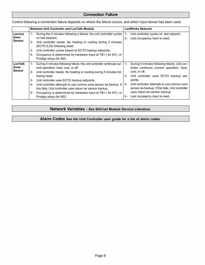
Page 8
Connection Failure
Control following a connection failure depends on where the failure occurs, and which input device has been used.
Between Unit Controller and LonTalk Module LonWorks Network
LennoxZoneSensor
1− During the 5 minutes following a failure, the unit controller cycles
on last setpoint.
2− Unit controller resets. No heating or cooling during 2 minutes
(ECTO 5.25) following reset.
3− Unit controller cycles based on ECTO backup setpoints.
4− Occupancy is determined by hardware input at TB1 ( for M1), or
Prodigy setup (for M2).
1− Unit controller cycles on last setpoint.
2 − Last occupancy input is used.
LonTalkZoneSensor
1− During 5 minutes following failure, the unit controller continues cur-
rent operation: heat, cool, or off.
2− Unit controller resets. No heating or cooling during 5 minutes fol-
lowing reset.
3− Unit controller uses ECTO backup setpoints.
4− Unit controller attempts to use Lennox zone sensor as backup. If
this fails, Unit controller uses return air sensor backup.
5− Occupancy is determined by hardware input at TB1 ( for M1), or
Prodigy setup (for M2).
1− During 5 minutes following failure, Unit con-
troller continues current operation: heat,
cool, or off.
2− Unit controller uses ECTO backup set-
points.
3− Unit controller attempts to use Lennox zone
sensor as backup. If this fails, Unit controller
uses return−air−sensor backup.
4 − Last occupancy input is used.
Network Variables − See BACnet Module Service Literature.
Alarm Codes See the Unit Controller user guide for a list of alarm codes.

Page 1
CONTROLSKITS AND ACCESSORIES Litho U.S.A.
506693-01 10/2014Supersedes 5/2014
Prodigy® LonTalk®
MODULE KIT
INSTALLATION INSTRUCTIONS FOR LONTALK® MODULE KIT (54W27)USED WITH ENERGENCE® ROOFTOP UNITS
WARNINGImproper installation, adjustment, alteration, service ormaintenance can cause personal injury, loss of life, ordamage to property.
Installation and service must be performed by a licensedprofessional installer (or equivalent) or a service agency.
CAUTION
ELECTROSTATICDISCHARGE (ESD)
Precautions andProcedures
Electrostatic discharge can affectelectronic components. Takeprecautions during unit installationand service to protect the unit'selectronic controls. Precautions willhelp to avoid control exposure toelectrostaticdischargebyputtingtheunit, the control and the technician atthe same electrostatic potential.Neutralize electrostatic charge bytouching hand and all tools on anunpainted unit surface beforeperforming any service procedure
TABLE OF CONTENTS
General 1. . . . . . . . . . . . . . . . . . . . . . . . . . . . . . . . . . . . . .
Installation 1. . . . . . . . . . . . . . . . . . . . . . . . . . . . . . . . . . . .
Operation and Functional Description 3. . . . . . . . . . . .
Network Configuration Parameter Implementation 14.
Appendix A — Supply Airflow Targets 15. . . . . . . . . . . .
Appendix B — LonTalk® Occupancy Signals and Blower Operation 16. . . . . . . . . . . . . . . . . . . . . . . . . .
General
PRODUCT NAME
LonTalk® Control Kit, COCTRL65FF1 - Cat No. 54W27.
VERSION REQUIRED
This module requires either the Prodigy M2 Unit Controllerversion 7.07 or higher or Prodigy 2.0 M3 Unit controller.
The LonTalk module allows communication between theLennox Prodigy or Prodigy 2.0 unit controller and a
LonWorks® network. The module is LonMark certified to
design guidelines version 3.4.
TECHNICAL ASSISTANCE
For assistance, contact Lennox Technical Support at800-453-6669.
Installation
NOTE - a small flat-head screw driver is required to connect
the communication wire to the SmartWire� connector.
1. Remove power to the unit.
2. Open the compressor access doors.
3. Plug the LonTalk module (see LonTalk module in figure1) onto the M2 or M3 Unit Controller. Guide pins will alignthe module with the M2 or M3 unit controller connector.
4. Connect the LonTalk SmartWire� connector as shownin figures 1 or 2.
M2 UNIT CONTROLLER
This controller will automatically recognize the LonTalk®
module and begin communications provided the networkhas been correctly configured.
To configure the LonTalk network, go to:
SETTINGS > CONTROL = LONTALK
M3 UNIT CONTROLLER
To enable the LonTalk module, go to:
1. SETUP > INSTALL and run the setup wizard. WhenConfiguration ID 1 appears on the screen, configureposition 5 as L.
2. To configure the LonTalk Network, go to:
SETUP > NETWORK INTEGRATION = LONTALK
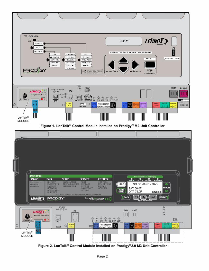
Page 2
LonTalk®
MODULE
Figure 1. LonTalk® Control Module Installed on Prodigy® M2 Unit Controller
NO DEMAND - OAS
ZAT: 56.0FDAT: 75.0F UNOCC
LonTalk®
MODULE
Figure 2. LonTalk® Control Module Installed on Prodigy®2.0 M3 Unit Controller
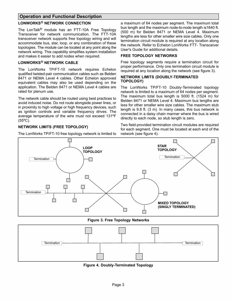
Page 3
Operation and Functional Description
LONWORKS® NETWORK CONNECTION
The LonTalk® module has an FTT-10A Free TopologyTransceiver for network communication. The FTT-10Atransceiver network supports free topology wiring and will
accommodate bus, star, loop, or any combination of thesetopologies. The module can be located at any point along thenetwork wiring. This capability simplifies system installationand makes it easier to add nodes when required.
LONWORKS® NETWORK CABLE
The LonWorks TP/FT-10 network requires Echelonqualified twisted-pair communication cables such as Belden8471 or NEMA Level 4 cables. Other Echelon approvedequivalent cables may also be used depending on the
application. The Belden 8471 or NEMA Level 4 cables arerated for plenum use.
The network cable should be routed using best practices toavoid induced noise. Do not route alongside power lines, orin proximity to high voltage or high frequency devices, suchas ignition controls and variable frequency drives. Theaverage temperature of the wire must not exceed 131ºF
(55ºC).
NETWORK LIMITS (FREE TOPOLOGY)
The LonWorks TP/FT-10 free topology network is limited to
a maximum of 64 nodes per segment. The maximum totalbus length and the maximum node-to-node length is1640 ft.(500 m) for Belden 8471 or NEMA Level 4. Maximumlengths are less for other smaller wire size cables. Only onetermination circuit module is required at any location alongthe network. Refer to Echelon LonWorks FTT- Transceiver
User's Guide for additional details.
FREE TOPOLOGY NETWORKS
Free topology segments require a termination circuit forproper performance. Only one termination circuit module isrequired at any location along the network (see figure 3).
NETWORK LIMITS (DOUBLY-TERMINATEDTOPOLOGY)
The LonWorks TP/FT-10 Doubly-Terminated topologynetwork is limited to a maximum of 64 nodes per segment.The maximum total bus length is 5000 ft. (1524 m) for
Belden 8471 or NEMA Level 4. Maximum bus lengths areless for other smaller wire size cables. The maximum stublength is 9.8 ft. (3 m). In many cases, this bus network isconnected in a daisy chain manner where the bus is wireddirectly to each node, so stub length is zero.
Two field-provided termination circuit modules are requiredfor each segment. One must be located at each end of the
network (see figure 4).
LOOPTOPOLOGY
Termination
STARTOPOLOGY
MIXED TOPOLOGY(SINGLY TERMINATED)
Termination
Termination
Figure 3. Free Topology Networks
TerminationTermination
Figure 4. Doubly‐Terminated Topology

Page 4
NETWORK BUS TERMINATION
To install the network bus terminal module 37X75, connectthe brown and yellow wires to the network bus that requiressingle termination and connect the brown and orange wireto the network bus that requires double termination. See
figure 7. The unused termination module wire must becovered with a wire nut to prevent potential groundingproblems.
NETWORK INTEGRATION
A network configuration tool such as LonMaker® is requiredto commission the LonWorks network. Press the service
button on the LonTalk® module to generate a servicemessage that contains the Neuron ID.
Other commissioning methods may be used. The Neuronaddress is located on the LonTalk module. An externalInterface File (XIF) is available for configuration prior toinstallation.
PRODIGY® RESET
The Prodigy unit controller may be reset using nviRequestwith enumeration RQ_RESET sent to NodeObject functionblock.
ZONE OR ROOM SENSOR CONTROL
In order to use room temperature setpoints, the Prodigy unit
controller must be configured for ZoneTemperature controlmode. This may be done through the Prodigy display.
Prodigy - M2 Zone Sensor Control ConfigurationProcedure:
In order to use nviSpaceIAQ, nviSpaceRH ornviSpaceTemp, the Prodigy M2 unit controller must beconfigured.
1. Go to the M2 Unit Controller user interface.
2. Use the select button to enter the menu, and use theup/down buttons to scroll through the options.
3. Go to:
SETTINGS > CONTROL > LONTALK > CONTROL
MODE and select ZONE for the Zone Temperature
control mode.
This is the same as setting the Prodigy ECTO
(Electronic Config To Order) parameter 6.01 to a value
of 1.
Prodigy 2.0 - M3 Room Sensor Control ConfigurationProcedure:
In order to use nviSpaceIAQ, nviSpaceRH ornviSpaceTemp, the Prodigy M3 unit controller must be
configured.
Go to the M3 Unit Controller user interface.
1. Go to:
SETTINGS > GENERAL > CONFIGURATION ID 1 and
verify or change position 5 is set to L.
2. Go to:
SETUP > NETWORK INTEGRATION and set to
LONTALK.
3. Set CONTROL MODE to either MONITOR ONLY orROOM SENSOR.
If ROOM SENSOR is selected, then enabled the
applicable sensors (CO2, RH or TEMP).
DATA UPDATE RATE
If nviSpaceTemp, nviOutdoorTemp, nviSpaceRH ornviSpaceIAQ are used, the data needs to be updated withinfive minutes to be valid.
LONMARK FUNCTION PROFILES
The Prodigy LonTalk module contains two LonMark®
functional profile function blocks, space comfortcontroller-rooftop and discharge air controller. It also
contains a Lennox specified functional block, a virtualfunction block containing the network configurationvariables and a node object. See figure 5.
NVI DUPLICATIONS
nviOccSchedule1, (in sccRooftop), and nviOccSchedule,(in dischargeAirCont), are duplicate network variable inputsand only one should be used.
Also, nviFanSpeedCmd and nviSupFanCap have the samefunctionality and only one should be used.
Both nviSetpoint and nviHCSetpoints change the effectivetemperature setpoints and only one of them should be used.

Page 5
sccRooftop
�nviApplicMod�nviAuxHeatEnable�nviComprEnable�nviEconEnable�nviEmergOverride�nviFanSpeedCmd�nviOAMinPos�nviOccManCmd�nviOccSchedule1�nviOccSensor�nviOutdoorTemp�nviSetpoint�nviSetptOffset�nviSpaceIAQ�nviSpaceRH�nviSpaceTemp
nvoCoolPrimary�nvoDischAirTem1�
nvoEffectOccup�nvoEffectSetpt�nvoFanSpeed�
nvoHeatPrimary�nvoHeatSecondary�
nvoLocalSpaceTmp�nvoOADamper�
nvoOutdoorTemp�nvoSetpoint�
nvoSpaceCO2�nvoSpaceRH�
nvoSpaceTemp�nvoUnitStatus�
nvoAirflow�
�nviBldgStaticSP�nviDACISP�nviDAHtSP�nviDuctStaticSP�nviExhFanCap�nviOccSchedule�nviPriCoolEnable�nviPriHeatEanble�nviSpaceDehumSP�nviSupFanCap
nvoBldStatPress�nvoDehumidifier�
nvoDischAirTemp�nvoDuctStatPress�nvoEconEnabled�
nvoEffDATempSP�nvoEffSpaceDHSP�nvoExhFanStatus�nvoLocalOATemp�
nvoRATemp�SupFanStatus�
nvoUnitStatus1�nvoOAFlow�
nvoBuildVersion�nvoCatalogNo�
nvoCurrentAlarms�nvoHCSetpoints�
nvoLocalSpaceCO2�nvoLocalSpaceRH�
nvoModelNo�nvoLocalSpaceTmp�nvoRecentEvent_1�nvoRecentEvent_2�nvoRecentEvent_3�nvoRecentEvent_4�nvoRecentEvent_5�nvoRecentEvent_6�nvoRecentEvent_7�nvoRecentEvent_8�nvoRecentEvent_9�
nvoRecentEvent_10�nvoRunTimeBlower�
nvoRunTimeComp_1�nvoRunTimeComp_2�nvoRunTimeComp_3�nvoRunTimeComp_4�nvoRunTempFrCool�nvoRunTimeHeat_1�nvoRunTimeHeat_2�nvoRunTimeHeat_3�nvoRunTimeHeat_4�nvoRunTimeHotGas�
nvoRunTimeMaint�nvoTimePowrOn�
nvoSerialNo�nvoBlowRPM�
nvoBlowTorque�
��nviHCSetpoints
�nviRequest nvoStat�
�nciBldgStaticSP�nciBypassTime�nciDACISP�nciDAHtSP�nciDuctStatSP�nciFanOperation�nciLocation�nciOAMinPOS�nciOATSP�nciSetpoints�nciSndHrtBt�nciSpaceRHSetpt�nciSupAFSP�nciMinOAFSP
dischargeAirContlennox
NodeObject
Virtual Functional Blocks
Figure 5. Device Function Blocks

Page 6
Table 1. Network Variables (sorted alphabetically)SNVT Name SNVT Index SNVT Name SNVT Index SNVT Name SNVT Index
nciBldgStaticSP 40 nviSetpoint 8 nvoOAFlow 101
nciBypassTime 104 nviSetptOffset 9 nvoOutdoorTemp 35
nciDAClSP 38 nviSpaceDehumSP 53 nvoRATemp 63
nciDAHtSP 39 nviSpaceIAQ 20 nvoRecentEvent_1 71
nciDuctStatSP 41 nviSpaceRH 19 nvoRecentEvent_2 72
nciFanOperation 66 nviSpaceTemp 7 nvoRecentEvent_3 73
nciLocation 1 nviSupFanCap 48 nvoRecentEvent_4 74
nciMinOAFlowSP 43 nvoAirflow 100 nvoRecentEvent_5 75
nciOAMinPos 5 nvoBldgStatPress 60 nvoRecentEvent_6 76
nciOATSP 42 nvoBlowRPM 102 nvoRecentEvent_7 77
nciSetpoints 4 nvoBlowTorque 103 nvoRecentEvent_8 78
nciSndHrtBt 0 nvoBuildVersion 86 nvoRecentEvent_9 79
nciSpaceRHSetpt 6 nvoCatalogNo 85 nvoRecentEvent10 80
nciSupAFSP 67 nvoCoolPrimary 32 nvoRunTimeBlower 99
nviApplicMode 22 nvoCurrentAlarms 70 nvoRunTimeComp_1 88
nviAuxHeatEnable 15 nvoDehumidifier 65 nvoRunTimeComp_2 89
nviBldgStaticSP 50 nvoDischAirTem1 29 nvoRunTimeComp_3 90
nviComprEnable 14 nvoDischAirTemp 54 nvoRunTimeComp_4 91
nviDAClSP 46 nvoDuctStatPress 57 nvoRunTimeFrCool 92
nviDAHtSP 47 nvoEconEnabled 61 nvoRunTimeHeat_1 95
nviDuctStaticSP 45 nvoEffDATempSP 56 nvoRunTimeHeat_2 96
nviEconEnable 16 nvoEffectOccup 26 nvoRunTimeHeat_3 97
nviEmergOverride 17 nvoEffectSetpt 25 nvoRunTimeHeat_4 98
nviExhFanCap 49 nvoEffSpaceDHSP 64 nvoRunTimeHotGas 93
nviFanSpeedCmd 13 nvoExhFanStatus 59 nvoRunTimeMaint 87
nviHCSetpoints 68 nvoFanSpeed 28 nvoRunTimePowrOn 94
nviOAMinPos 21 nvoHCSetpoints 69 nvoSerialNo 84
nviOccManCmd 11 nvoHeatPrimary 30 nvoSetpoint 27
nviOccSchedule 44 nvoHeatSecondary 31 nvoSpaceCO2 36
nviOccSchedule1 10 nvoLocalOATemp 62 nvoSpaceRH 34
nviOccSensor 12 nvoLocalSpaceCO2 81 nvoSpaceTemp 23
nviOutdoorTemp 18 nvoLocalSpaceRH 82 nvoStatus 3
nviPriCoolEnable 51 nvoLocalSpaceTmp 37 nvoSupFanStatus 58
nviPriHeatEnable 52 nvoModelNo 83 nvoUnitStatus 24
nviRequest 2 nvoOADamper 33 nvoUnitStatus1 55
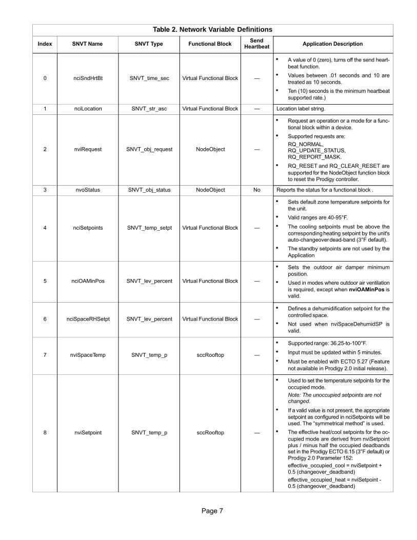
Page 7
Table 2. Network Variable Definitions
Index SNVT Name SNVT Type Functional BlockSend
HeartbeatApplication Description
0 nciSndHrtBt SNVT_time_sec Virtual Functional Block —
� A value of 0 (zero), turns off the send heart
beat function.
� Values between .01 seconds and 10 are
treated as 10 seconds.
� Ten (10) seconds is the minimum heartbeat
supported rate.)
1 nciLocation SNVT_str_asc Virtual Functional Block — Location label string.
2 nviRequest SNVT_obj_request NodeObject —
� Request an operation or a mode for a func
tional block within a device.
� Supported requests are:
RQ_NORMAL, RQ_UPDATE_STATUS, RQ_REPORT_MASK.
� RQ_RESET and RQ_CLEAR_RESET are
supported for the NodeObject function blockto reset the Prodigy controller.
3 nvoStatus SNVT_obj_status NodeObject No Reports the status for a functional block .
4 nciSetpoints SNVT_temp_setpt Virtual Functional Block —
� Sets default zone temperature setpoints for
the unit.
� Valid ranges are 40-95°F.
� The cooling setpoints must be above the
corresponding heating setpoint by the unit'sauto-changeover dead-band (3°F default).
� The standby setpoints are not used by the
Application
5 nciOAMinPos SNVT_lev_percent Virtual Functional Block —
� Sets the outdoor air damper minimum
position.
� Used in modes where outdoor air ventilation
is required, except when nviOAMinPos isvalid.
6 nciSpaceRHSetpt SNVT_lev_percent Virtual Functional Block —
� Defines a dehumidification setpoint for the
controlled space.
� Not used when nviSpaceDehumidSP is
valid.
7 nviSpaceTemp SNVT_temp_p sccRooftop —
� Supported range: 36.25-to-100°F.
� Input must be updated within 5 minutes.
� Must be enabled with ECTO 5.27 (Feature
not available in Prodigy 2.0 initial release).
8 nviSetpoint SNVT_temp_p sccRooftop —
� Used to set the temperature setpoints for the
occupied mode.
Note: The unoccupied setpoints are notchanged.
� If a valid value is not present, the appropriate
setpoint as configured in nciSetpoints will beused. The “symmetrical method” is used.
� The effective heat/cool setpoints for the oc
cupied mode are derived from nviSetpointplus / minus half the occupied deadbandsset in the Prodigy ECTO 6.15 (3°F default) orProdigy 2.0 Parameter 152:
effective_occupied_cool = nviSetpoint +0.5 (changeover_deadband)
effective_occupied_heat = nviSetpoint -0.5 (changeover_deadband)

Page 8
Table 2. Network Variable Definitions
Index Application DescriptionSend
HeartbeatFunctional BlockSNVT TypeSNVT Name
9 nviSetptOffset SNVT_temp_p sccRooftop —
Used to shift the effective occupied temperaturesetpoints by adding nviSetptOffset to the current setpoints.
10* nviOccSchedule1 SNVT_tod_event sccRooftop —Only current state occupancy mode issupported.
* See Appendix B for further information.
11* nviOccManCmd SNVT_occupancy sccRooftop —Used to command the Space ComfortController into different occupancy mode
12* nviOccSensor SNVT_occupancy sccRooftop —Used to indicate the presence of occupants inthe controlled space .
13 nviFanSpeedCmd SNVT_switch sccRooftop — Used to set the unit's blower speed.
14 nviComprEnable SNVT_switch sccRooftop — Used to disable compressor operation.
15 nviAuxHeatEnable SNVT_switch sccRooftop — Used to disable auxiliary heat operation.
16 nviEconEnable SNVT_switch sccRooftop —Used to enable and disable economizeroperation.
17 nviEmergOverride SNVT_hvac_emerg sccRooftop —
� Used to command the device into different
emergency modes.
� Supported enumerations:
EMERG_NORMALEMERG_PRESSURIZEEMERG_DEPRESSURIZEEMERG_PURGEEMERG_SHUTDOWNEMERG_NUL
18 nviOutdoorTemp SNVT_temp_p sccRooftop —� Supported range: -30.6 to 131.6°F.
� Input must be updated within 5 minutes.
19 nviSpaceRH SNVT_lev_percent sccRooftop —� Input must be updated within 5 minutes.
� Must be enabled with ECTO 5.27
20 nviSpaceIAQ SNVT_ppm sccRooftop —
� Supported range: 0 to 2,000 ppm.
� Input must be updated within 5 minutes.
� Must be enabled with ECTO 5.27 (Feature
not available in Prodigy 2.0 initial release).
21 nviOAMinPos SNVT_lev_percent sccRooftop —
� Used to provide a dynamic minimum
position setpoint for an outdoor air damper.
� When valid it will supersede nciOAMinPos.
22 nviApplicMode SNVT_hvac_mode sccRooftop —
� Used to set the unit's operating mode. Sup
ported values:
AUTO, HEAT ONLY, COOL ONLY, FANONLY, OFF
� Must be updated within 120 minutes, if
used.
23 nvoSpaceTemp SNVT_temp_p sccRooftop Yes
� This output is the effective space
temperature value that the control is using.
� The support range is 36 to 100°F.
24 nvoUnitStatus SNVT_hvac_status sccRooftop Yes Reports the controller status.
25 nvoEffectSetpt SNVT_temp_p sccRooftop YesReports the current effective space temperaturesetpoint.
26* nvoEffectOccup SNVT_occupancy sccRooftop NoReports the effective occupancy state (seeAppendix B).
27 nvoSetpoint SNVT_temp_p sccRooftop NoReports the current setpoint without theapplication of nviSetptOffset.

Page 9
Table 2. Network Variable Definitions
Index Application DescriptionSend
HeartbeatFunctional BlockSNVT TypeSNVT Name
28 nvoFanSpeed SNVT_switch sccRooftop Yes Reports the current unit blower speed
29 nvoDischAirTemp SNVT_temp_p sccRooftop No� Reports the discharge temperature value.
� Supported range, -8 to +163°F.
30 nvoHeatPrimary SNVT_lev_percent sccRooftop Yes Reports the current primary heat output value.
31 nvoHeatSecondary SNVT_lev_percent sccRooftop YesReports the current secondary heat outputvalue, (heat pumps only).
32 nvoCoolPrimary SNVT_lev_percent sccRooftop Yes Reports the current cooling output value.
33 nvoOADamper SNVT_lev_percent sccRooftop YesReports the current outdoor air damperposition.
34 nvoSpaceRH SNVT_lev_percent sccRooftop YesReports the effective space relative humidityvalue.
35 nvoOutdoorTemp SNVT_temp_p sccRooftop Yes
� Reports the effective outdoor temperature
value.
� Supported range, -30 to +130°F.
36 nvoSpaceCO2 SNVT_ppm sccRooftop Yes
� Reports the effective space carbon dioxide
value.
� Supported range, 0 to 2,000 ppm.
37 nvoLocalSpaceTmp SNVT_temp_p sccRooftop Yes
� Reports the space temperature measured
by the locally wire sensor.
� Supported range, 36 to 100°F.
38 nciDAClSP SNVT_temp_p Virtual Functional Block —
� Sets the default discharge air cooling
temperature setpoint.
� Supported range: 40 to 80°F.
39 nciDAHtSP SNVT_temp_p Virtual Functional Block —
� Sets the default discharge air heating
temperature setpoint.
� Supported range: 80 to 140°F.
40 nciDuctStatSP SNVT_press_p Virtual Functional Block —
� Sets the default duct static pressure set
point.
� Supported range: 0 to 1245 Pa.
41 nciOATSP SNVT_temp_p Virtual Functional Block —
� Sets the outdoor air temperature setpoint to
enable free-cooling for units with economizers.
� Supported range: 40 to 70°F.
42 nciBldgStaticSP SNVT_press_p Virtual Functional Block —
� Sets the default building static pressure set
point for exhaust control.
� Supported range -124.5 to 124.5 Pa.
43 nciMinOAFlowSP SNVT_flow Virtual Functional Block —
� Set the default outdoor airflow for EP
enabled roof top units.
� Supported range – 0 to 150 cfm/ton
� Multiply the CFM/ton value with tonnage of
the unit to derive the value in CFM.
44 nviOccSchedule SNVT_tod_event dischargeAirCont — Only current state is supported.
45 nviDuctStaticSP SNVT_press_p dischargeAirCont —� Sets the duct static pressure setpoint.
� Supported range: 0 to 1245 Pa.
46 nviDAClSP SNVT_temp_p dischargeAirCont —
� Sets the discharge air cooling temperature
setpoint.
� Supported range: 40 to 80°F.

Page 10
Table 2. Network Variable Definitions
Index Application DescriptionSend
HeartbeatFunctional BlockSNVT TypeSNVT Name
47 nviDAHtSP SNVT_temp_p dischargeAirCont —
� Sets the discharge air heating temperaturesetpoint.
� Supported range: 80 to 140°F.
48 nviSupFanCap SNVT_lev_percent dischargeAirCont — Sets the unit's blower speed.
49 nviExhFanCap SNVT_lev_percent dischargeAirCont — Sets the unit's exhaust fan speed.
50 nviBldgStaticSP SNVT_press_p dischargeAirCont —
� Sets the building static pressure setpoint forexhaust control.
� Supported range −124.5 to 124.5 Pa.
51 nviPriCoolEnable SNVT_switch dischargeAirCont — Used to disable compressor operation.
52 nviPriHeatEnable SNVT_switch dischargeAirCont — Used to disable primary heating operation.
53 nviSpaceDehumSP SNVT_lev_percent dischargeAirCont — Sets the dehumidification RH setpoint.
54 nvoDischAirTemp SNVT_temp_p sccRooftop No� Reports the discharge air temperature.
� Supported range: -8 to 131°F..
55 nvoUnitStatus1 SNVT_hvac_status dischargeAirCont YesReports the controller status. Same asnvoUnitStatus in sccRooftop function block.
56 nvoEffDATempSP SNVT_temp_p dischargeAirCont YesReports the effective discharge air temperaturesetpoint.
57 nvoDuctStatPress SNVT_press_p dischargeAirCont Yes� Reports the duct static pressure.
� Supported range: 0 to 1245 Pa.
58 nvoSupFanStatus SNVT_switch dischargeAirCont Yes Reports unit blower speed.
59 nvoExhFanStatus SNVT_switch dischargeAirCont Yes Reports exhaust fan speed.
60 nvoEconEnabled SNVT_switch dischargeAirCont Yes Reports free−cooling status of economizer.
61 nvoBldgStatPress SNVT_press_p dischargeAirCont Yes� Reports the building static pressure.
� Supported range: -124.5 to +124.5 Pa.
62 nvoLocalOATemp SNVT_temp_p dischargeAirCont Yes
� Reports locally measured outdoortemperature.
� Supported range: -30 to +130°F.
63 nvoRATemp SNVT_temp_p dischargeAirCont Yes� Reports effective return air temperature.
� Supported range: -8 to +163°F.
64 nvoEffSpaceDHSP SNVT_press_p dischargeAirCont YesReports effective relative humidity setpoint fordehumidification.
65 nvoDehumidifier SNVT_switch dischargeAirCont Yes Reports status of dehumidification operation.
66 nciFanOperation SCPTfanOperation Virtual Functional Block —Sets the operation mode for the unit blowerduring occupied state.
67 nciSupAFSP UNVT_SupAF_Stps Virtual Functional Block —
� Sets the default Airflow settings for a
SmartAirflow™ enabled roof top units inlit/sec units.
� For valid ranges please refer to the
Appendix A.
68 nviHCSetpoints SNVT_temp_setpt lennox —
� Valid ranges are 40-to-95°F (cooling).
� The cooling setpoints must be above the
corresponding heating setpoint by the unit'sAutochangeover Deadband (ECTO 6.15,3°F default or Prodigy 2.0 Parameter 152).
� The standby set points are not used by the
Application

Page 11
Table 2. Network Variable Definitions
Index Application DescriptionSend
HeartbeatFunctional BlockSNVT TypeSNVT Name
69 nvoHCSetpoints SNVT_temp_setpt lennox No
� Reports zone temperature setpoints.
� Standby setpoints are not used and arereturned with the unoccupied values.
70 nvoCurrentAlarms UNVT_currentAlarms lennox Yes Reports currently active alarms codes.
71 nvoRecentEvent_1 UNVT_event lennox YesReports most recent alarm code with time ofoccurrence.
72 nvoRecentEvent_2 UNVT_event lennox NoReports second most recent alarm with time ofoccurrence.
73 nvoRecentEvent_3 UNVT_event lennox No
Reports alarm with time of occurrence.
74 nvoRecentEvent_4 UNVT_event lennox No
75 nvoRecentEvent_5 UNVT_event lennox No
76 nvoRecentEvent_6 UNVT_event lennox No
77 nvoRecentEvent_7 UNVT_event lennox No
78 nvoRecentEvent_8 UNVT_event lennox No
79 nvoRecentEvent_9 UNVT_event lennox No
80 nvoRecentEvent10 UNVT_event lennox No
81 nvoLocalSpaceCO2 SNVT_ppm lennox No
� Reports locally measured space carbondioxide level.
� Supported range: 0 to 2,000 ppm.
82 nvoLocalSpaceRH SNVT_lev_percent lennox NoReports locally measured space relativehumidity level.
83 nvoModelNo SNVT_str_asc lennox No Reports unit model number.
84 nvoSerialNo SNVT_str_asc lennox No Reports unit serial number.
85 nvoCatalogNo SNVT_str_asc lennox No Report unit catalog number.
86 nvoBuildVersion SNVT_str_asc lennox No Reports firmware version string.
87 nvoRunTimeMaint UNVT_maint_runtimes lennox NoReports air filter, blower belt and UV lamprun-times.
88 nvoRunTimeComp_1 UNVT_minutes_cycles lennox NoReports run-time and cycle count forcompressor 1.
89 nvoRunTimeComp_2 UNVT_minutes_cycles lennox NoReports run-time and cycle count forcompressor 2.
90 nvoRunTimeComp_3 UNVT_minutes_cycles lennox NoReports run-time and cycle count forcompressor 3.
91 nvoRunTimeComp_4 UNVT_minutes_cycles lennox NoReports run-time and cycle count forcompressor 4.
92 nvoRunTimeFrCool UNVT_minutes_cycles lennox NoReports run-time and cycle count for freecooling operation.
93 nvoRunTimeHotGas UNVT_minutes_cycles lennox NoReports run-time and cycle count for hot gasbypass dehumidification.
94 nvoRunTimePowrOn UNVT_minutes_cycles lennox NoReports run-time and cycle count for unit poweron.
95 nvoRunTimeHeat_1 UNVT_minutes_cycles lennox NoReports run-time and cycle count for heat stage1.
96 nvoRunTimeHeat_2 UNVT_minutes_cycles lennox NoReports run-time and cycle count for heat stage2.
97 nvoRunTimeHeat_3 UNVT_minutes_cycles lennox NoReports run-time and cycle count for heat stage3.
98 nvoRunTimeHeat_4 UNVT_minutes_cycles lennox NoReports run-time and cycle count for heat stage4.

Page 12
Table 2. Network Variable Definitions
Index Application DescriptionSend
HeartbeatFunctional BlockSNVT TypeSNVT Name
99 nvoRunTimeBlower UNVT_minutes_cycles lennox No Reports run-time and cycle count for blower.
100 nvoAirflow SNVT_flow ssRooftop Yes
� Reports the amount of current supply air
flow.
� Supported range: 0480 cfm/ton
101 nvoOAFlow SNVT_flow dischargeAirCont Yes� Reports the amount of outdoor airflow.
� Supported range: 0480 cfm/ton
102 nvoBlowRPM SNVT_rpm lennox Yes� Reports the blower motor speed.
� Supported range: 01500 rpm
103 nvoBlowTorque SNVTlev_percent lennox Yes� Reports the PWM of an ECM blower motor.
� Supported range: 0 – 100 %
104 nciBypassTime SNVT_time_min Virtual Function Block —
� This configuration defines the maximum
amount of time that the controller can be inthe bypass (occupancy) mode following asingle bypass request from either a local(hardwired) bypass switch ornviOccManCmd.
� Additional Bypass requests can restart the
timer.
* See Appendix B for further information.

Page 13
Table 3. Variable Type Definitions
SNVT Type Definition
SCPTfanOperation
fan_operation_tEnumeration, 1 byte
Value Identifier Notes
-1 (0xFF) HVF_NUL Invalid Value
1 HVF_CYCLE Fan cycles with heating andcooling
2 HVF_CON_CYCLE Continuous in occupied, cycles in occupied standby
SNVT_hvac_emergemerg_tEnumeration, 1 byte
SNVT_hvac_modehvac_tEnumeration, 1 byte
SNVT_hvac_status
typedef struct { hvac_t mode; signed long heat_output_primary; signed long heat_output_secondary; signed long cool_output; signed long econ_output; signed long fan_output; unsigned short in_alarm;} SNVT_hvac_status;
SNVT_lev_percent
Signed Long, 2 bytesValid Type Range: -163.840 .. 163.830Type Resolution: 0.005Invalid Value: 32,767 (0x7FFF)
SNVT_occupancyoccup_t Enumeration, 1 byte
SNVT_ppm
Unsigned Long, 2 bytesValid Range: 0 .. 65,535 Parts per Million (ppm)
SNVT_press_p
Signed Long, 2 bytesValid Type -32768 .. 32,766 Pascals Invalid Value 32,767 (0x7FFF)
SNVT_str_ascASCII character string with NUL terminator30 characters max, 31 bytes
SNVT_switch
typedef struct { unsigned value; signed state;} SNVT_switch;value: percentage of full scale, resolution0.5%state: can either be -1 (NULL), 0 (OFF), or 1(ON)
SNVT_temp_p
Temperature Signed Long 2 bytesValid Range: -273.17 .. 327.66 Resolution: 0.01 Degrees Celsius Invalid Value: 32,767 (0x7FFF)
SNVT_temp_setpt
typedef struct { signed long occupied_cool; signed long standby_cool; signed long unoccupied_cool; signed long occupied_heat; signed long standby_heat; signed long unoccupied_heat;} SNVT_temp_setpt;
SNVT_flow
Flow VolumeUnsigned Long, 2 bytesValid Range: 0 .. 65,534 lit/secResolution: 1 lit/secConvert to CFM 1 cfm = 0.4719474432 lit/sec
SNVT_rpm
Revolutions per minuteUnsigned Long, 2 bytesValid Range: 0 .. 65,534 RPMResolution: 1 RPM
SNVT Type Definition
SNVT_time_min
Elapsed Time Signed Long, 2 bytesValid Range: 0 .. 65,535 MinutesResolution: 1 Minute
SNVT_time_sec
Elapsed Time Signed Long, 2 bytesValid Range: 0 .. 6,5535 SecondsResolution: .01 Seconds
SNVT_time_stamp
typedef struct { signed long year; unsigned short month; unsigned short day; unsigned short hour; unsigned short minute; unsigned short second;} SNVT_time_stamp;
SNVT_tod_event
typedef struct { occup_t current_state; occup_t next_state; unsigned long time_to_next_state;}SNVT_tod_event
UNVT_currentAlarms
typedef struct { unsigned short AlarmCount; event_code_t AlarmCode1; event_code_t AlarmCode2; event_code_t AlarmCode3; event_code_t AlarmCode4; event_code_t AlarmCode5; event_code_t AlarmCode6; event_code_t AlarmCode7;}UNVT_currentAlarms;
UNVT_event
typedef struct { event_code_t Event; struct EventStatus { unsigned reserved :1; unsigned currentlyActiveAlarm :1; unsigned UnitOffOnAlarm :1; unsigned reserved5bits :5; }; SNVT_time_stamp EventTime;};UNVT_event
UNVT_maint_runtimes
typedef struct { signed quad filter_time_minutes; signed quad belt_time_minutes; signed quad UV_lamp_time_minutes;}UNVT_maint_runtimes;
UNVT_minutes_cycles
typedef struct { signed quad minutes; signed quad cycles;}UNVT_minutes_cycles;
UNVT_SupAF_Stps
typedef struct { unsigned long HeatSP; unsigned long HiCoolSP; unsigned long MHCoolSP; unsigned long MLCoolSP; unsigned long LoCoolSP; unsigned long VentSP; unsigned long SmokeSP;}UNVT_SupAF_StpsAll the above parameters follow the same unitconvention as SNVT_flow.
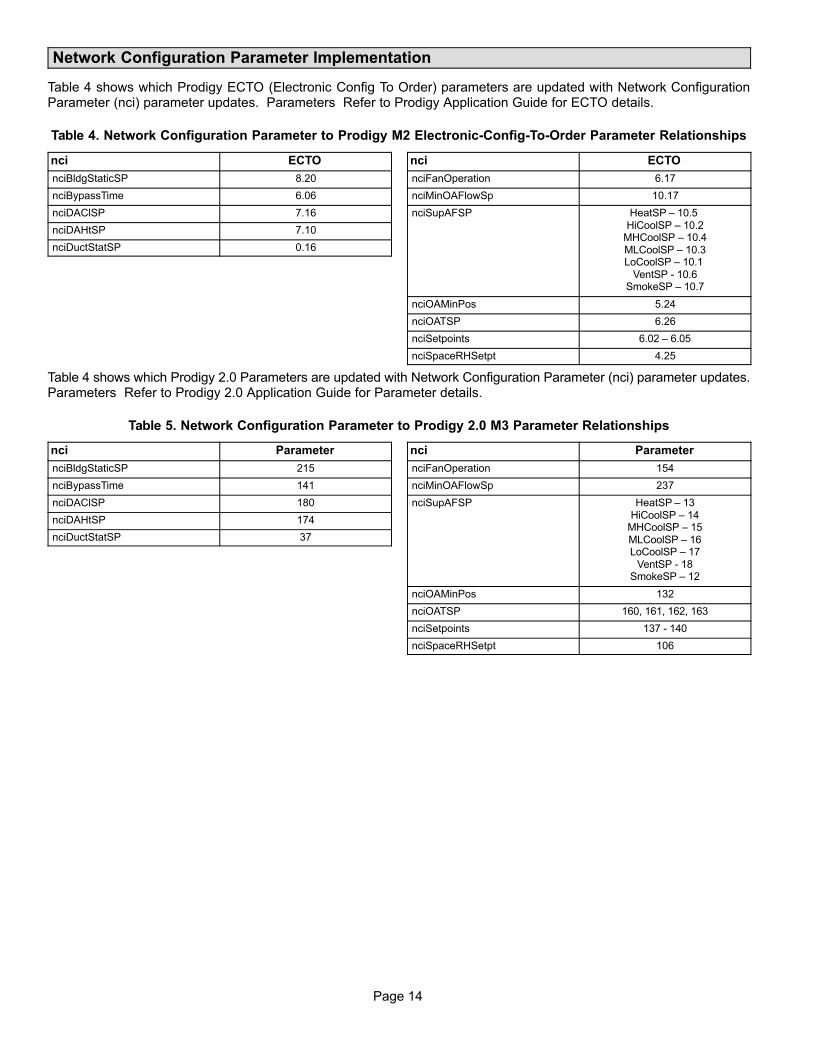
Page 14
Network Configuration Parameter Implementation
Table 4 shows which Prodigy ECTO (Electronic Config To Order) parameters are updated with Network ConfigurationParameter (nci) parameter updates. Parameters Refer to Prodigy Application Guide for ECTO details.
Table 4. Network Configuration Parameter to Prodigy M2 Electronic-Config-To-Order Parameter Relationships
nci ECTO
nciBldgStaticSP 8.20
nciBypassTime 6.06
nciDAClSP 7.16
nciDAHtSP 7.10
nciDuctStatSP 0.16
nci ECTO
nciFanOperation 6.17
nciMinOAFlowSp 10.17
nciSupAFSP HeatSP – 10.5 HiCoolSP – 10.2
MHCoolSP – 10.4MLCoolSP – 10.3LoCoolSP – 10.1
VentSP 10.6SmokeSP – 10.7
nciOAMinPos 5.24
nciOATSP 6.26
nciSetpoints 6.02 – 6.05
nciSpaceRHSetpt 4.25
Table 4 shows which Prodigy 2.0 Parameters are updated with Network Configuration Parameter (nci) parameter updates.Parameters Refer to Prodigy 2.0 Application Guide for Parameter details.
Table 5. Network Configuration Parameter to Prodigy 2.0 M3 Parameter Relationships
nci Parameter
nciBldgStaticSP 215
nciBypassTime 141
nciDAClSP 180
nciDAHtSP 174
nciDuctStatSP 37
nci Parameter
nciFanOperation 154
nciMinOAFlowSp 237
nciSupAFSP HeatSP – 13HiCoolSP – 14
MHCoolSP – 15MLCoolSP – 16LoCoolSP – 17
VentSP 18SmokeSP – 12
nciOAMinPos 132
nciOATSP 160, 161, 162, 163
nciSetpoints 137 - 140
nciSpaceRHSetpt 106
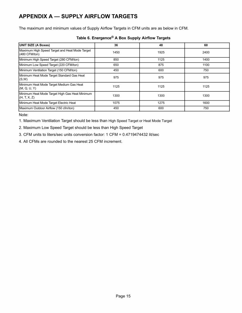
Page 15
APPENDIX A — SUPPLY AIRFLOW TARGETS
The maximum and minimum values of Supply Airflow Targets in CFM units are as below in CFM.
Table 6. Energence® A Box Supply Airflow Targets
UNIT SIZE (A Boxes) 36 48 60
Maximum High Speed Target and Heat Mode Target(480 CFM/ton)
1450 1925 2400
Minimum High Speed Target (280 CFM/ton) 850 1125 1400
Minimum Low Speed Target (220 CFM/ton) 650 875 1100
Minimum Ventilation Target (150 CFM/ton) 450 600 750
Minimum Heat Mode Target Standard Gas Heat(S,W)
975 975 975
Minimum Heat Mode Target Medium Gas Heat (M, Q, U, Y)
1125 1125 1125
Minimum Heat Mode Target High Gas Heat Minimum(H, T, X, Z)
1300 1300 1300
Minimum Heat Mode Target Electric Heat 1075 1275 1600
Maximum Outdoor Airflow (150 cfm/ton) 450 600 750
Note:
1. Maximum Ventilation Target should be less than High Speed Target or Heat Mode Target
2. Maximum Low Speed Target should be less than High Speed Target
3. CFM units to liters/sec units conversion factor: 1 CFM = 0.4719474432 lit/sec
4. All CFMs are rounded to the nearest 25 CFM increment.

Page 16
APPENDIX B — LONTALK® OCCUPANCY SIGNALS AND BLOWER OPERATION
This section describes how LonTalk® occupancy signals are combined to produce effective occupancy along with theapplicable unit controller parameter setting.
PRODIGY M2 UNIT CONTROLLER BLOWER OPERATIONS WITH EFFECTIVE OCCUPANCY
This section describes how LonTalk® occupancy signals are
combined to produce effective occupancy.
The blower runs to service heat and cool demands,regardless of the space occupancy. But when there is noheating or cooling demand there are options for how theblower should operate in conjunction with occupancysignals to keep the space ventilated, or the air stirred.
In SETTINGS > CONTROL menus the option for BLOWERON OCP is selected as CYCLES or ALWAYS ON. Thesecorrespond to ECTO 6.17 settings of 0 or 1, respectively.These settings govern whether the blower runs continuouslywhen the space is considered occupied (=1), or cycles on/offwith the heating and cooling demand (=0). ECTO 6.17 only
applies to the room sensor control modes, and not to thelocal or network thermostat modes. In those modes theblower is controlled by the G thermostat or DDC signal.
To comply with the California Energy Commission Title 24standard there are two additional blower/occupancysettings that are set directly by changing ECTO 6.17 fromthe SETTINGS>CONTROL > ECTO menu. These twoadditional options are available when using LonTalk thatsupplies a room occupancy signal (in addition to thescheduled occupancy).
There are two new CEC Title 24 settings for ECTO 6.17.Those two options are 2 and 3 and a description of both areprovided in table 7.
Table 7. ECTO 6.17 Description
ECTO6.17
Occupancy Blower Duty Description
0 Blower cycles on/off with demand. (Legacy usage.)
1 Blower runs when either the occupancy sensor or schedule, or both, indicates occupied. (Legacy usage.)
2 Blower runs when both the occupancy sensor and schedule indicate occupied.
3The same as option 2, but blower runs for 30 minutes and is off for 90 minutes when schedule is occupied but the occupancy sensor isnot occupied.
Table 8. Blower Operation Description
Blower Operation Description
On Blower runs continuously.
Cycles Blower cycles on/off with demand.
Cycles w/Stir Blower cycles on/off with demand; during off cycle blower is on 30 minutes of 120.
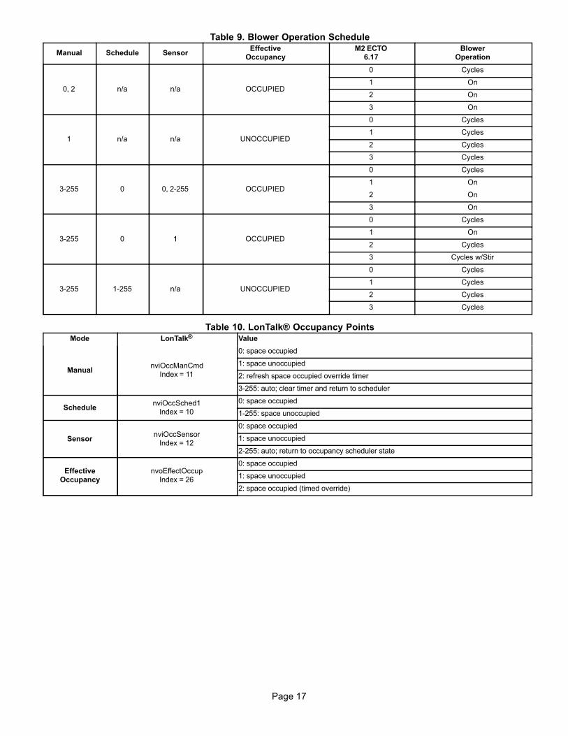
Page 17
Table 9. Blower Operation Schedule
Manual Schedule SensorEffective
OccupancyM2 ECTO
6.17Blower
Operation
0, 2 n/a n/a OCCUPIED
0 Cycles
1 On
2 On
3 On
1 n/a n/a UNOCCUPIED
0 Cycles
1 Cycles
2 Cycles
3 Cycles
3255 0 0, 2-255 OCCUPIED
0 Cycles
1 On
2 On
3 On
3255 0 1 OCCUPIED
0 Cycles
1 On
2 Cycles
3 Cycles w/Stir
3255 1255 n/a UNOCCUPIED
0 Cycles
1 Cycles
2 Cycles
3 Cycles
Table 10. LonTalk® Occupancy PointsMode LonTalk® Value
ManualnviOccManCmd
Index = 11
0: space occupied
1: space unoccupied
2: refresh space occupied override timer
3255: auto; clear timer and return to scheduler
SchedulenviOccSched1
Index = 10
0: space occupied
1255: space unoccupied
SensornviOccSensor
Index = 12
0: space occupied
1: space unoccupied
2255: auto; return to occupancy scheduler state
EffectiveOccupancy
nvoEffectOccupIndex = 26
0: space occupied
1: space unoccupied
2: space occupied (timed override)

Page 18
PRODIGY 2.0 M3 UNIT CONTROLLER BLOWER OPERATIONS WITH EFFECTIVE OCCUPANCY
This section describes how LonTalk® occupancy signals are
combined to produce effective occupancy.
The blower runs to service heat and cool demands,regardless of the space occupancy. However when there isno heating or cooling demand there are options for how theblower should operate in conjunction with occupancysignals to keep the space ventilated, or the air stirred.
1. California Energy Commission Title 24
A. The legacy option settings for OCC Blower Modeare AUTO CYCLES or ON-CONTINUOUS 1. Thesesettings govern whether the blower runscontinuously when the space is considered occupiedor cycles on/off with the heating and cooling demand.
B. To comply with the California Energy CommissionTitle 24 standard there are two additional values forOCC Blower Mode which are ON-CONTINUOUS 2and ON-CONTINUOUS 3. See table 11 for theirdescriptions.
C. These two new options are available when usingLonTalk that supplies a room occupancy signal (inaddition to the scheduled occupancy).
2. Enabling Network Type
To enable the network module, go to SETUP >
INSTALL and run the setup wizard. When
Configuration ID 1 appears on the screen, configure
position 5 to L = LonTalk.
3. Menu Setup Procedure Method for OCC BlowerMode
These blower control options are handled by the OCC
Blower Mode. These setting can be changed using the
following menu path:
Go to SETUP > NETWORK INTEGRATION >
NETWORK = LONTALK > (additional prompts
concerning network configuration and sensor
types will be asked) CONTROL MODE = ROOM
SENSOR > ROOM SENSOR OCC BLOWER MODE =
(see table 11).
Table 11. Blower Operation Description
OCC Blower Mode Description
AUTO CYCLES Blower cycles on/off with demand. (Legacy usage.)
ON-CONTINUOUS 1
Blower runs when either the occupancy sensor or schedule, or both, indicates occupied. (Legacy usage.)
ON-CONTINUOUS 2
Blower runs when both the occupancy sensor and schedule indicate occupied.
ON-CONTINUOUS 3
The same as option 2, but blower runs for 30 minutes and is off for 90 minutes when schedule is occupied but the occupancysensor is not occupied.
Table 12. LonTalk® Occupancy PointsMode LonTalk® Value
ManualnviOccManCmd
Index = 11
0: space occupied
1: space unoccupied
2: refresh space occupied override timer
3255: auto; clear timer and return to scheduler
SchedulenviOccSched1
Index = 10
0: space occupied
1255: space unoccupied
SensornviOccSensor
Index = 12
0: space occupied
1: space unoccupied
2255: auto; return to occupancy scheduler state
EffectiveOccupancy
nvoEffectOccupIndex = 26
0: space occupied
1: space unoccupied
2: space occupied (timed override)
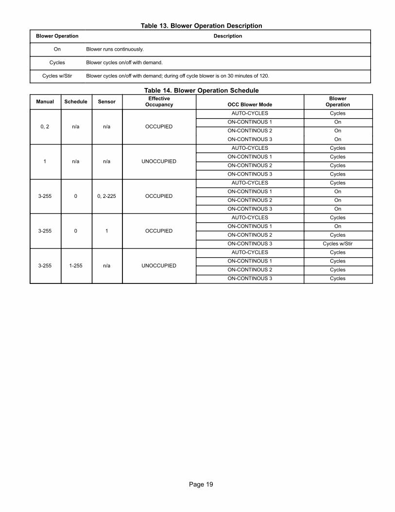
Page 19
Table 13. Blower Operation Description
Blower Operation Description
On Blower runs continuously.
Cycles Blower cycles on/off with demand.
Cycles w/Stir Blower cycles on/off with demand; during off cycle blower is on 30 minutes of 120.
Table 14. Blower Operation Schedule
Manual Schedule SensorEffective
Occupancy OCC Blower ModeBlower
Operation
0, 2 n/a n/a OCCUPIED
AUTO-CYCLES Cycles
ON-CONTINOUS 1 On
ON-CONTINOUS 2 On
ON-CONTINOUS 3 On
1 n/a n/a UNOCCUPIED
AUTO-CYCLES Cycles
ON-CONTINOUS 1 Cycles
ON-CONTINOUS 2 Cycles
ON-CONTINOUS 3 Cycles
3255 0 0, 2-225 OCCUPIED
AUTO-CYCLES Cycles
ON-CONTINOUS 1 On
ON-CONTINOUS 2 On
ON-CONTINOUS 3 On
3255 0 1 OCCUPIED
AUTO-CYCLES Cycles
ON-CONTINOUS 1 On
ON-CONTINOUS 2 Cycles
ON-CONTINOUS 3 Cycles w/Stir
3255 1255 n/a UNOCCUPIED
AUTO-CYCLES Cycles
ON-CONTINOUS 1 Cycles
ON-CONTINOUS 2 Cycles
ON-CONTINOUS 3 Cycles

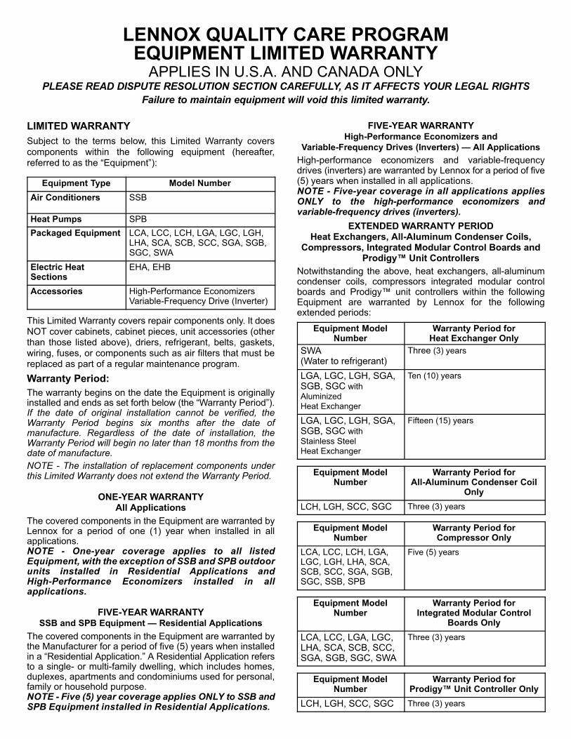
LENNOX QUALITY CARE PROGRAMEQUIPMENT LIMITED WARRANTY
APPLIES IN U.S.A. AND CANADA ONLYPLEASE READ DISPUTE RESOLUTION SECTION CAREFULLY, AS IT AFFECTS YOUR LEGAL RIGHTS
Failure to maintain equipment will void this limited warranty.
LIMITED WARRANTY
Subject to the terms below, this Limited Warranty coverscomponents within the following equipment (hereafter,referred to as the “Equipment”):
Equipment Type Model Number
Air Conditioners SSB
Heat Pumps SPB
Packaged Equipment LCA, LCC, LCH, LGA, LGC, LGH,LHA, SCA, SCB, SCC, SGA, SGB,SGC, SWA
Electric Heat Sections
EHA, EHB
Accessories High-Performance EconomizersVariable-Frequency Drive (Inverter)
This Limited Warranty covers repair components only. It doesNOT cover cabinets, cabinet pieces, unit accessories (otherthan those listed above), driers, refrigerant, belts, gaskets,wiring, fuses, or components such as air filters that must bereplaced as part of a regular maintenance program.
Warranty Period:
The warranty begins on the date the Equipment is originallyinstalled and ends as set forth below (the “Warranty Period”).If the date of original installation cannot be verified, theWarranty Period begins six months after the date ofmanufacture. Regardless of the date of installation, theWarranty Period will begin no later than 18 months from thedate of manufacture.
NOTE - The installation of replacement components underthis Limited Warranty does not extend the Warranty Period.
ONE-YEAR WARRANTYAll Applications
The covered components in the Equipment are warranted byLennox for a period of one (1) year when installed in allapplications.NOTE - One-year coverage applies to all listedEquipment, with the exception of SSB and SPB outdoorunits installed in Residential Applications andHigh-Performance Economizers installed in allapplications.
FIVE-YEAR WARRANTYSSB and SPB Equipment — Residential Applications
The covered components in the Equipment are warranted bythe Manufacturer for a period of five (5) years when installedin a “Residential Application.” A Residential Application refersto a single- or multi-family dwelling, which includes homes,duplexes, apartments and condominiums used for personal,family or household purpose.NOTE - Five (5) year coverage applies ONLY to SSB andSPB Equipment installed in Residential Applications.
FIVE-YEAR WARRANTYHigh-Performance Economizers and
Variable-Frequency Drives (Inverters) — All Applications
High-performance economizers and variable-frequencydrives (inverters) are warranted by Lennox for a period of five(5) years when installed in all applications.NOTE - Five-year coverage in all applications appliesONLY to the high-performance economizers andvariable-frequency drives (inverters).
EXTENDED WARRANTY PERIODHeat Exchangers, All-Aluminum Condenser Coils,
Compressors, Integrated Modular Control Boards andProdigy� Unit Controllers
Notwithstanding the above, heat exchangers, all-aluminumcondenser coils, compressors integrated modular controlboards and Prodigy� unit controllers within the followingEquipment are warranted by Lennox for the followingextended periods:
Equipment ModelNumber
Warranty Period forHeat Exchanger Only
SWA(Water to refrigerant)
Three (3) years
LGA, LGC, LGH, SGA,SGB, SGC with Aluminized Heat Exchanger
Ten (10) years
LGA, LGC, LGH, SGA,SGB, SGC with Stainless Steel Heat Exchanger
Fifteen (15) years
Equipment ModelNumber
Warranty Period forAll-Aluminum Condenser Coil
Only
LCH, LGH, SCC, SGC Three (3) years
Equipment ModelNumber
Warranty Period forCompressor Only
LCA, LCC, LCH, LGA,LGC, LGH, LHA, SCA,SCB, SCC, SGA, SGB,SGC, SSB, SPB
Five (5) years
Equipment ModelNumber
Warranty Period forIntegrated Modular Control
Boards Only
LCA, LCC, LGA, LGC,LHA, SCA, SCB, SCC,SGA, SGB, SGC, SWA
Three (3) years
Equipment ModelNumber
Warranty Period forProdigy� Unit Controller Only
LCH, LGH, SCC, SGC Three (3) years
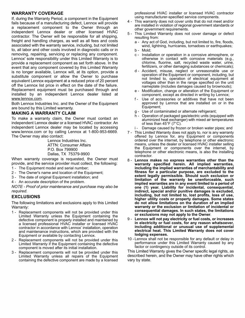
WARRANTY COVERAGEIf, during the Warranty Period, a component in the Equipmentfails because of a manufacturing defect, Lennox will providea replacement component to the Owner through anindependent Lennox dealer or other licensed HVACcontractor. The Owner will be responsible for all shipping,freight and handling charges, as well as all fees and costsassociated with the warranty service, including, but not limitedto, all labor and other costs involved in diagnostic calls or inremoving, repairing, servicing or replacing any component.Lennox' sole responsibility under this Limited Warranty is toprovide a replacement component as set forth above. In theevent that any component covered by this Limited Warrantyis no longer available, Lennox will, at its option, provide asubstitute component or allow the Owner to purchaseequivalent Lennox equipment at a reduced price of 20 percentoff the Lennox list price in effect on the date of the failure.Replacement equipment must be purchased through andinstalled by an independent Lennox dealer listed atwww.lennox.com.Both Lennox Industries Inc. and the Owner of the Equipmentare bound by this Limited warranty.
MAKING A WARRANTY CLAIMTo make a warranty claim, the Owner must contact anindependent Lennox dealer or a licensed HVAC contractor. Anindependent Lennox dealer may be located by accessingwww.lennox.com or by calling Lennox at 1-800-953-6669.The Owner may also contact:
Lennox Industries Inc.ATTN: Consumer AffairsP.O. Box 799900Dallas, TX 75379-9900
When warranty coverage is requested, the Owner mustprovide, and the service provider must collect, the following:1 - The Equipment model and serial number;2 - The Owner's name and location of the Equipment;3 - The date of original Equipment installation; and4 - An accurate description of the problem.
NOTE - Proof of prior maintenance and purchase may also berequired.
EXCLUSIONS
The following limitations and exclusions apply to this LimitedWarranty:1 - Replacement components will not be provided under this
Limited Warranty unless the Equipment containing thedefective component is properly installed and maintained bya licensed professional HVAC installer or licensed HVACcontractor in accordance with Lennox’ installation, operationand maintenance instructions, which are provided with theEquipment or available by contacting Lennox.
2 - Replacement components will not be provided under thisLimited Warranty if the Equipment containing the defectivecomponent is moved after its initial installation.
3 - Replacement components will not be provided under thisLimited Warranty unless all repairs of the Equipmentcontaining the defective component are made by a licensed
professional HVAC installer or licensed HVAC contractorusing manufacturer-specified service components.
4 - This warranty does not cover units that do not meet and/orare installed in violation of regional government standards orother government requirements.
5 - This Limited Warranty does not cover damage or defectresulting from:a - Any act of God, including, but not limited to, fire, floods,
wind, lightning, hurricanes, tornadoes or earthquakes;b - Mold;c - Installation or operation in a corrosive atmosphere, or
otherwise in contact with corrosive materials (e.g.,chlorine, fluorine, salt, recycled waste water, urine,fertilizers, or other damaging substances or chemicals);
d - Accident, misuse, neglect or unreasonable use oroperation of the Equipment or component, including, butnot limited to, operation of electrical equipment atvoltages other than in the range specified on the unitnameplate (includes damages caused by brownouts);
e - Modification, change or alteration of the Equipment orcomponent, except as directed in writing by Lennox;
f - Use of accessories or additives that have not beenapproved by Lennox that are installed on or in theEquipment;
g - Use of contaminated or alternate refrigerant;h - Operation of packaged gas/electric units (equipped with
aluminized heat exchanger) with mixed air temperaturesof less than 45°F (7°C).
i - Damage caused by frozen or broken water pipes; and7 - This Limited Warranty does not apply to, nor is any warranty
offered by Lennox for, any Equipment or componentsordered over the internet, by telephone or other electronicmeans, unless the dealer or licensed HVAC installer sellingthe Equipment or components over the internet, bytelephone or other electronic means, is also the installingcontractor.
8 - Lennox makes no express warranties other than thewarranty specified herein. All implied warranties,including the implied warranties of merchantability andfitness for a particular purpose, are excluded to theextent legally permissible. Should such exclusion orlimitation of the warranty be unenforceable, suchimplied warranties are in any event limited to a period ofone (1) year. Liability for incidental, consequential,indirect, special and/or punitive damages is excluded,including, but not limited to, lost profits, loss of use,higher utility costs or property damages. Some statesdo not allow limitations on the duration of an impliedwarranty or the exclusion or limitation of incidental orconsequential damages. In such states, the limitationsor exclusions may not apply to the Owner.
9 - Lennox will not pay electricity or fuel costs, or increasesin electricity or fuel costs, for any reason whatsoever,including additional or unusual use of supplementalelectrical heat. This Limited Warranty does not coverlodging expenses.
10 - Lennox shall not be responsible for any default or delay inperformance under this Limited Warranty caused by anyfactor or contingency outside of its control.
This Limited Warranty gives the Owner specific legal rights, asdescribed herein, and the Owner may have other rights whichvary by state.
DISPUTE RESOLUTIONNOTE - Please read this section carefully as it affects yourrights and the resolution of Disputes.1 - Contact Lennox: Please report any Dispute (defined in
items 1 and 2 on page 4) to:
Lennox Industries Inc.ATTN: Consumer AffairsP.O. Box 799900Dallas, TX 75379-9900
2 - Mandatory Arbitration: Both the Owner and Lennoxagree that all Disputes must be resolved exclusivelythrough final and binding arbitration, and not by acourt or jury; however, Owner or Lennox may assertclaims in small claims court if (i) the claims qualify forsmall claims court, (ii) the matter remains in smallclaims court, and (iii) the matter proceeds only on anindividual (not a class or representative) basis.
Both the Owner and Lennox waive the right to a trial byjury and any right to have a Dispute heard in court.Instead, all Disputes must be resolved in arbitration by aneutral third-party arbitrator. In arbitration, Disputes areresolved by an arbitrator instead of a judge or jury,discovery is more limited than in court and the arbitrator’sdecision is subject to limited review by courts. However,the arbitrator must follow the law and can award the samedamages as in court, including monetary damages,injunctive relief, declaratory relief and other relief. Thearbitrator’s award can be confirmed in any court ofcompetent jurisdiction.A single arbitrator, with the American ArbitrationAssociation (“AAA”), will conduct the arbitration, and theaward may not exceed the relief allowed by applicablelaw. The arbitration will be conducted in the county ofOwner’s residence or other mutually agreed location. Forclaims of $50,000 or less, the AAA’s SupplementaryProcedures for consumer-related Disputes will apply. Forclaims over $50,000, the AAA’s Commercial ArbitrationRules will apply. If either set of rules is not available, theAAA rules applicable to consumer Disputes apply. TheAAA’s rules and a form initiating arbitration proceedingsare available at www.adr.org or by calling1-800-778-7879.
This arbitration provision is subject to the FederalArbitration Act (“FAA”), which governs its interpretationand enforcement. To the extent the FAA does not apply toany Dispute, the laws of the State of Texas, without regardto principles of conflicts of law, will apply. The arbitrator willdecide all issues of interpretation and application of this“Dispute Resolution” section, the arbitration provision andthe Limited Warranty, with the exception of decidingwhether the Arbitration Class Action Waiver in Paragraph2a is valid or enforceable. A court will resolve any questionregarding the validity or enforceability of Paragraph 2a.This Dispute Resolution section will survive termination ofthis Limited Warranty. The requirement to arbitrate will bebroadly interpreted.
a - Arbitration Class Action Waiver: The Owner andLennox agree that arbitration will proceed solely onan individual basis and no Dispute will be arbitratedas a class action, consolidated with the claims of anyother party, or arbitrated on a consolidated,representative or private attorney general basis.
Unless the Owner and Lennox agree otherwise inwriting, the arbitrator’s authority to resolve and makeawards is limited to Disputes between Owner andLennox. The arbitrator’s award or decision will notaffect issues or claims involved in any proceedingbetween Lennox and any person or entity who is nota party to the arbitration. The arbitrator may awardmonetary, declaratory or injunctive relief only in favorof the individual party seeking relief and only to theextent necessary to provide relief warranted by thatparty’s individual claim. The arbitrator’s award, if any,will not apply to any person or entity that is not a partyto the arbitration.
A court, not the arbitrator, will decide any questionsregarding the enforceability of this Paragraph 2a. If acourt deems any portion of this Paragraph 2a invalidor unenforceable, the entire arbitration provision inParagraph 2 (other than this sentence) will be null andvoid and not apply.
b - Agency Proceedings: This arbitration agreementdoes not preclude the Owner from bringing issues tothe attention of federal, state, or local agencies. Suchagencies can, if the law allows, seek relief againstLennox on the Owner’s behalf.
c - Fees and Costs: If the Owner’s total damage claimsin an arbitration are $25,000 or less, not including theOwner’s attorney fees (“Small Arbitration Claim”), thearbitrator may, if the Owner prevails, award theOwner’s reasonable attorney fees, expert fees andcosts (separate from Arbitration Costs as definedbelow), but may not grant Lennox its attorney fees,expert fees or costs (separate from Arbitration Costs)unless the arbitrator determines that the Owner’sclaim was frivolous or brought in bad faith. In a SmallArbitration Claim case, Lennox will pay all arbitrationfiling, administrative and arbitrator costs (together,“Arbitration Costs”). The Owner must submit anyrequest for payment of Arbitration Costs to the AAAat the same time the Owner submits its Demand forArbitration. However, if the Owner wants Lennox toadvance the Arbitration Costs for a Small ArbitrationClaim before filing, Lennox will do so at the Owner’swritten request which must be sent to Lennox at theaddress in paragraph 1. In a Small Arbitration Claimcase, Lennox agrees that the Owner may choose tohave the arbitration carried out based only ondocuments submitted to the arbitrator or by atelephonic hearing unless the arbitrator requires anin-person hearing.
If the Owner’s total damage claim in an arbitrationexceeds $25,000, not including the Owner’s attorneyfees (“Large Arbitration Claim”), the arbitrator mayaward the prevailing party its reasonable attorneys’fees and costs, or it may apportion attorneys’ fees andcosts between the Owner and Lennox (such fees andcosts being separate from Arbitration Costs). In aLarge Arbitration Claim case, if the Owner is able todemonstrate that the Arbitration Costs will beprohibitive as compared to the costs of litigation,Lennox will pay as much of the Arbitration Costs asthe arbitrator deems necessary to prevent thearbitration from being cost-prohibitive.
d - OPT OUT: BOTH AN ORIGINAL ANDSUBSEQUENT OWNER MAY OPT OUT OFARBITRATION BY PROVIDING WRITTEN NOTICE(THE “OPT-OUT NOTICE”) TO LENNOX that ispost-marked no later than 30 calendar days after theOwner’s purchase of the equipment (in the case of theoriginal owner) or purchase of the premises at whichthe equipment was originally installed (in the case ofa subsequent owner). The Opt-Out Notice must bemailed to Lennox at:
Lennox Industries Inc.ATTN: Consumer AffairsP.O. Box 799900Dallas, TX 75379-9900
The Opt–Out Notice must state (i) the Owner’s nameand address, (ii) the date that the Owner purchasedthe equipment (if the original owner) or the premiseswhere the equipment was originally installed (in thecase of a subsequent owner), (iii) the equipment’smodel name and number, (iv) the equipment serialnumber (which can be found on the unit nameplate),and (v) that that the Owner elects to opt out ofarbitration. The Owner must sign the Opt-Out Noticepersonally and not through another person or entity,and the Opt-Out Notice will apply only to the personor entity that signs it. Neither the Owner nor any otherperson or entity can opt out of arbitration on behalf ofanyone else. Providing a timely Opt-Out Notice is theonly way to opt out of arbitration. Opting out ofarbitration will not affect the Limited Warranty, and theOwner will continue to enjoy the benefits of theLimited Warranty if the Owner opts out of arbitration.Any Opt-Out Notice received after the opt outdeadline will not be valid.
3 - Non-Arbitration Class Action and Jury Waiver: If forany reason any Dispute proceeds in court rather thanarbitration, the Owner and Lennox waive any right to a jurytrial, the Dispute will proceed solely on an individual,non-class, non-representative basis and neither theOwner nor Lennox may be a class representative or classmember or otherwise participate in any class,consolidated, private attorney general or representativeproceeding.
4 - Severability: The Owner and Lennox agree that, with theexception of any of the provisions in paragraph 2(a)(“Arbitration Class Action Waiver”), if an arbitrator or courtdecides that any part of this Dispute Resolution section isinvalid or unenforceable, the other parts of this DisputeResolution section shall still apply. If paragraph 2(a) isfound to be invalid or unenforceable thereby rendering allof paragraph 2 of the Dispute Resolution section null andvoid, paragraph 3 of that section shall survive and remainin full force and effect.
DEFINITIONS
In addition to the terms defined above, the following definitionswill apply to this Limited Warranty:1 - The terms “Dispute” and “Disputes” will be broadly
interpreted to include any claims, disagreements orcontroversies that the Owner and Lennox had, have ormay have against each other, whether based in contract
or tort or on a statute or regulation or any other legaltheory, including, without limitation, all claims,disagreements or controversies related in any way to orarising in any way out of:
a - the Equipment and components covered by thisLimited Warranty;
b - any other Lennox equipment, component or service;
c - any Lennox advertising, representation or marketing;
d - any contract, warranty, or other agreement the Ownerhad or has with Lennox;
e - any Lennox billing or other policy or practice;
f - any action or inaction by any Lennox officer, director,employee, agent, or other representative relating toany Lennox equipment, component, marketing,representation or service;
g - any claims the Owner brings against a third party(such as a distributor, dealer or repair service) that arebased on, relate to or in any way arise out of anyLennox equipment, component, marketing,representation or service;
h - any claims Lennox brings against the Owner; and
i - any aspect of the relationship between the Owner andLennox.
2 - “Dispute” and “Disputes” includes claims, disagreementsor controversies that arose at any time, including beforethis Limited Warranty became operative and after thisLimited Warranty is terminated.
3 - “Lennox” refers to Lennox International Inc., LennoxIndustries Inc., as well as their parents, affiliatedcompanies, related companies, subsidiaries, divisions,departments, business units, representatives,predecessors in interest, successors, and assigns.
4 - “Limited Warranty” refers to this document.
5 - “Owner” refers to (i) the person or entity that originallypurchased the Equipment from an independent Lennoxdealer or other licensed professional HVAC contractorand (ii) during the Warranty Period, the owner(s) andsubsequent owner(s) of the premises where theEquipment is originally installed.
EQUIPMENT INFORMATION
NOTE TO CUSTOMERPlease complete information below and retain thiswarranty for records and future reference.
Unit Model Number:Serial Number:Installing Contractor:Installation Date: Phone:
FORM W-022-L3 -- 09/1/2015Supersedes 04/1/2014
©2015 Lennox Industries Inc.Litho U.S.A.
P.O. Box 799900, Dallas, TX 75379-9900