user’s manual 5,000 btu room air conditioner model: sca052mwb1€¦ · user’s manual 5,000 btu...
TRANSCRIPT
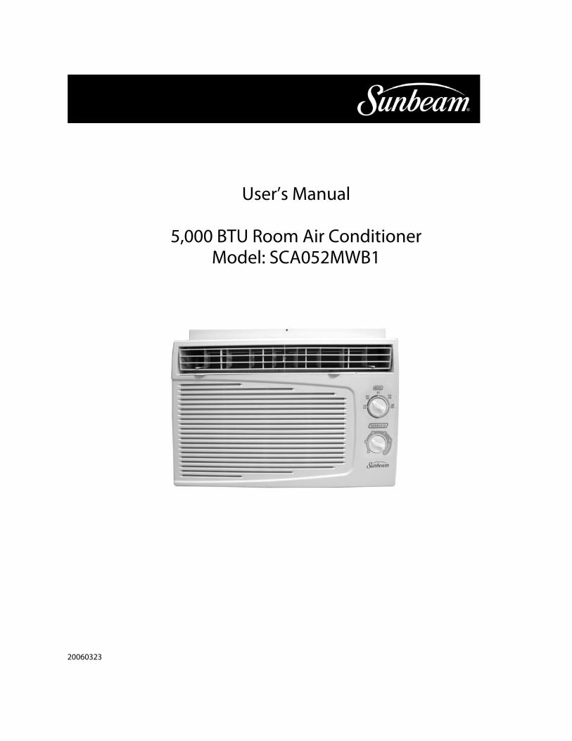
User’s Manual
5,000 BTU Room Air Conditioner
Model: SCA052MWB1
20060323
Table of C ontents
P arts Identification
Introduction
E lectrical S pecifications
T ips B efore Installation
Installation Instructions
Operating Instructions
C are and Maintenance
T roubleshooting G uide
P age
2
2
4
5
6
9
13
14
2
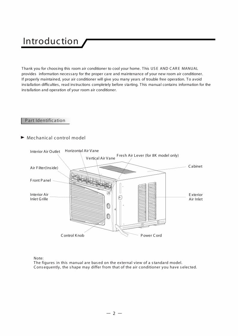
Introduc tion
T hank you for choosing this room air conditioner to cool your home. T his US E AND C AR E MANUALprovides information necessary for the proper care and maintenance of your new room air conditioner. If properly maintained, your air conditioner will give you many years of trouble free operation. T o avoid installation difficulties , read instructions completely before starting. T his manual contains information for the installation and operation of your room air conditioner.
C abinet
E xteriorAir Inlet
Interior Air Outlet
C ontrol K nob
Note:T he figures in this manual are bas ed on the external view of a s tandard model.C ons equently, the s hape may differ from that of the air c onditioner you have s elec ted.
P ower C ord
F ront P anel
Horizontal Air V ane
V ertical Air V aneF resh Air Lever (for 8K model only)
Interior Air Inlet G rille
Air F ilter(Ins ide)
P art Identific ation
Mec hanic al c ontrol model
1. All wiring must comply with local and nationalelectrical codes and must be installed by a licensed electrician. Once you have any questions regarding the following instructions , contact a licensed electrician.
2. C heck available power supply and resolve anywiring problems B E F OR E installing and operating this unit.
3. F or your safety and protection, this unit isgrounded through the power cord whenplugged into a matching wall outlet. If you arenot s ure whether your wall outlet is properlygrounded, pleas e c ons ult a lic ens edelec tric ian.
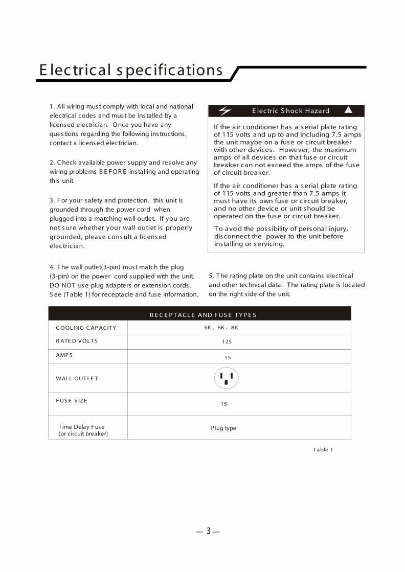
4. T he wall outlet(3-pin) must match the plug(3-pin) on the power cord supplied with the unit.DO NOT use plug adapters or extens ion cords .S ee (T able 1) for receptacle and fuse information.
5. T he rating plate on the unit contains electrical and other technical data. T he rating plate is located on the right s ide of the unit.
If the air conditioner has a serial plate ratingof 115 volts and up to and including 7.5 ampsthe unit maybe on a fuse or circuit breakerwith other devices . However, the maximum amps of all devices on that fuse or circuit breaker can not exceed the amps of the fuseof circuit breaker.
If the air conditioner has a serial plate ratingof 115 volts and greater than 7.5 amps it must have its own fuse or circuit breaker, and no other device or unit should be operated on the fuse or circuit breaker.
T o avoid the poss ibility of personal injury, disconnect the power to the unit before installing or servicing.
E lec tric S hoc k Hazard
E lec tric al s pec ific ations
125
5K 6K 8K
T able 1
15
15
R ATE D V OLT S
C OOLING C AP ACIT Y
AMP S
F US E S IZE
WALL OUT LE T
R E C E P T A CL E A ND F US E T Y P E S
!
T ime Delay F use (or circuit breaker)
P lug type
3
T ips before ins tallation
Y our R oom Air C onditioner unit is des igned to be highly efficient and save energy. F ollow these
recommendations for greater efficiency.
1. S elect thermostat setting that suits your comfort needs and leave the thermostat at that chosen setting.
2. T he air filter is very efficient in removing airborneparticles . K eep the air filter clean. T ypically, filtershould be cleaned once a month. Morefrequent cleaning may be necessary depending on outdoor and indoor air quality.
3. Use drapes , curtains , or shades to keepdirect sunlight from heating your room, but DO NOT obstruct the air conditioner. Allow air to circulate around the unit without obstructions .
4. S tart your air conditioner before outdoor air becomes hot and uncomfortable. T his avoids an initial period of discomfort while the unit is cooling off the room.
5. When outdoor temperature is cool enough, use HIG H or L OW F A N only. T his circulates indoor air, providingsome cooling comfort, and utilizes less electricity than when operating on a cooling setting.
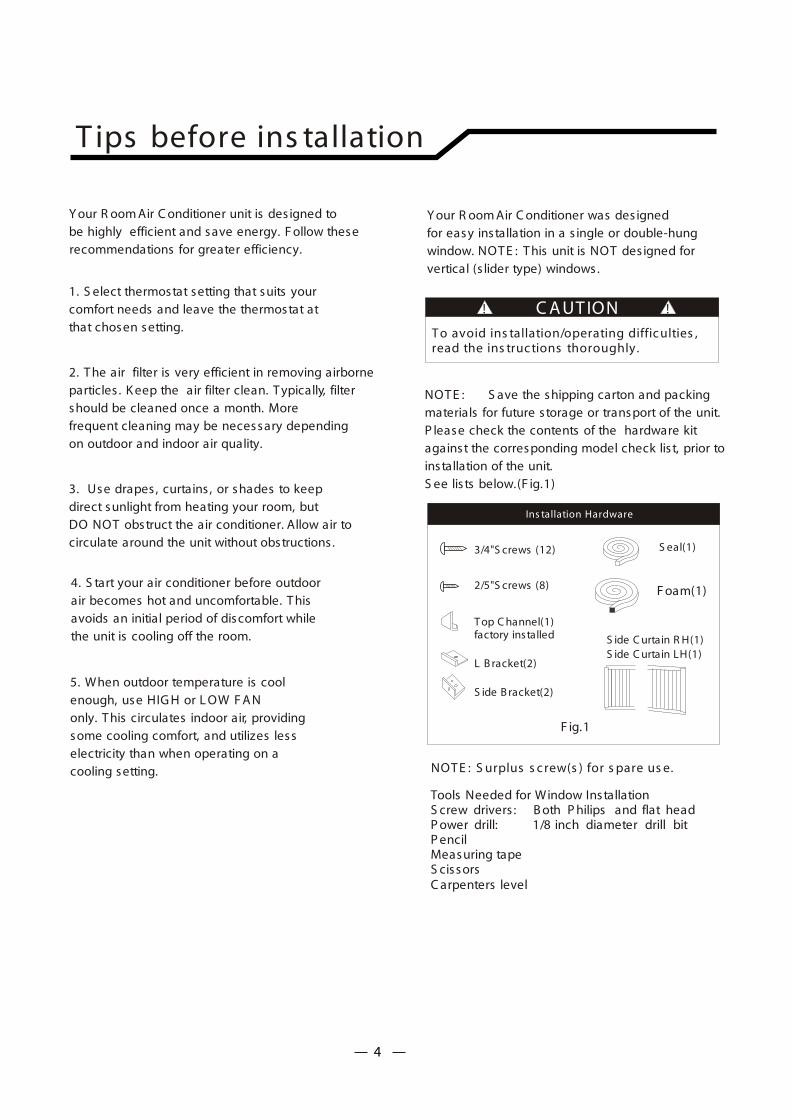
2/5"S crews (8)
T op C hannel(1)factory installed S ide C urtain R H(1)
S ide C urtain LH(1)
Ins tallation Hardware
3/4"S crews (12) S eal(1)
F oam(1)
Tools Needed for Window InstallationS crew drivers : B oth P hilips and flat headP ower drill: 1/8 inch diameter drill bitP encilMeasuring tapeS cissorsC arpenters level
L B racket(2)
S ide B racket(2)
F ig.1
T o avoid ins tallation/operating diffic ulties ,read the ins truc tions thoroughly.
NOT E : S ave the shipping carton and packing materials for future storage or transport of the unit. P lease check the contents of the hardware kit against the corresponding model check lis t, prior to installation of the unit.S ee lis ts below.(F ig.1)
C A UT ION! !
Y our R oom Air C onditioner was des igned for easy installation in a s ingle or double-hung window. NOT E : T his unit is NOT des igned for vertical (s lider type) windows.
NOT E : S urplus s c rew(s ) for s pare us e.
4
Ins tallation ins truc tions
B ecause the compressor is located on the controls s ide of the unit (right s ide), this s idewill be heavier and more awkward to manipulate.Inadequate support on control s ide of the unitcan result in personal injury and damage to yourunit and property. T herefore, it is recommended to have someone ass is t you during the installationof this unit.
F. Your unit was des igned to evaporate condensation under normal conditions . However, under extreme humidity conditions , excess condensation may cause the base pan to overflow to the outs ide.T he unit should be installed where condensationrun-off cannot drip on pedestrians or neighboringproperties .
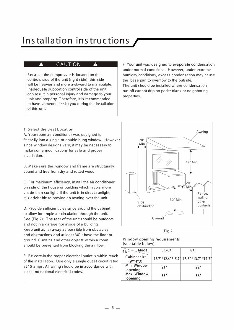
1. S elec t the B es t L oc ationA. Your room air conditioner was des igned to fit eas ily into a s ingle or double hung window. However,s ince window des igns vary, it may be necessary to make some modifications for safe and properinstallation.
B . Make sure the window and frame are s tructurallysound and free from dry and rotted wood.
C . F or maximum efficiency, install the air conditioneron s ide of the house or building which favors more shade than sunlight. If the unit is in direct sunlight, it is advisable to provide an awning over the unit.
D. P rovide sufficient clearance around the cabinetto allow for ample air circulation through the unit.S ee (F ig.2). T he rear of the unit should be outdoorsand not in a garage nor ins ide of a building.K eep unit as far away as poss ible from obstaclesand obstructions and at least 30" above the floor or ground. C urtains and other objects within a roomshould be prevented from blocking the air flow.
E . B e certain the proper electrical outlet is within reachof the installation. Use only a s ingle outlet circuit ratedat 15 amps. All wiring should be in accordance withlocal and national electrical codes .
.
Awning
Window opening requirements(s ee table below)
S ideobstruction
G round
F ence,wall, orotherobstacle.
12" Min.
30" Min.
20" Min.
20" Min.
C A UT ION! !
F ig.2
ModelModel 5K -6K5K -6K
21" 21"
35" 35" 36" 36"
22" 22"
17.7" *12.4" *15.7" 17.7" *12.4" *15.7" 18.5" *13.7" *17.7" 18.5" *13.7" *17.7"
8K 8K S izeS izeC abinet s ize (W*H*D) C abinet s ize (W*H*D) Min. Window opening Min. Window opening Max. Window openingMax. Window opening
5
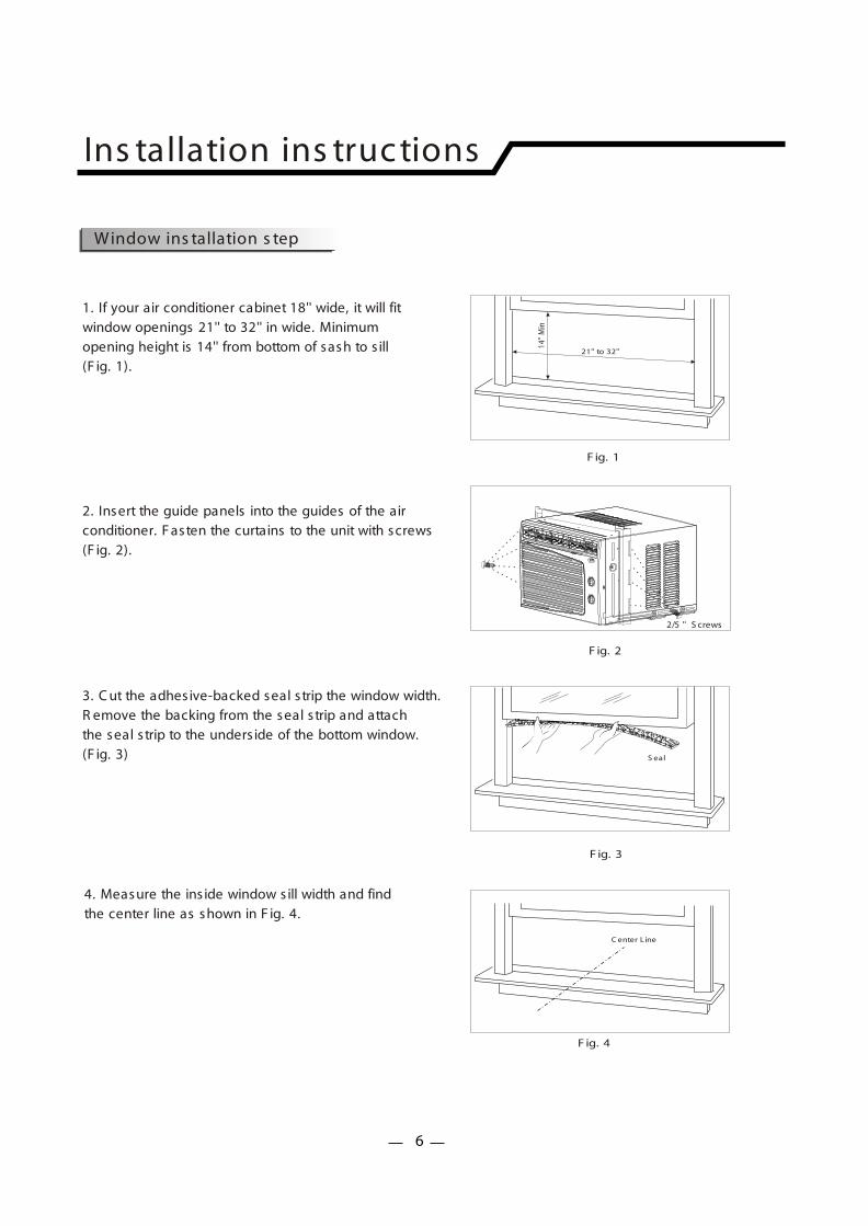
1. If your air conditioner cabinet 18'' wide, it will fit window openings 21'' to 32'' in wide. Minimum opening height is 14'' from bottom of sash to s ill(F ig. 1).
F ig. 1
Ins tallation ins truc tions
2. Insert the guide panels into the guides of the air conditioner. F asten the curtains to the unit with screws(F ig. 2).
F ig. 3
3. C ut the adhes ive-backed seal s trip the window width.R emove the backing from the seal s trip and attachthe seal s trip to the unders ide of the bottom window.(F ig. 3) S eal
21'' to 32''
14''
Min
4. Measure the ins ide window s ill width and findthe center line as shown in F ig. 4.
C enter Line
F ig. 4
Window ins tallation s tep
2/5 '' S crews
F ig. 2
6
Ins tallation ins truc tions
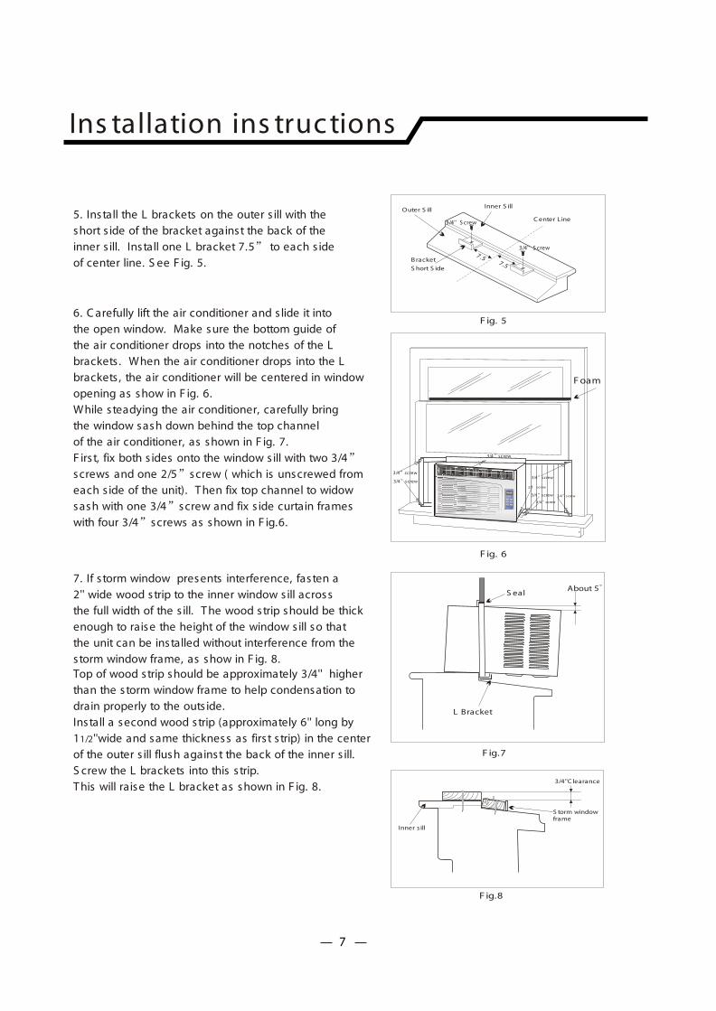
5. Install the L brackets on the outer s ill with the short s ide of the bracket against the back of the inner s ill. Install one L bracket 7.5 to each s ideof center line. S ee F ig. 5.
F ig. 5
C enter Line
S hort S ide
B racket
Inner S illOuter S ill
7.57.5
6. C arefully lift the air conditioner and s lide it intothe open window. Make sure the bottom guide of the air conditioner drops into the notches of the Lbrackets . When the air conditioner drops into the L brackets , the air conditioner will be centered in window opening as show in F ig. 6. While s teadying the air conditioner, carefully bringthe window sash down behind the top channel of the air conditioner, as shown in F ig. 7. F irs t, fix both s ides onto the window s ill with two 3/4screws and one 2/5 screw ( which is unscrewed fromeach s ide of the unit). T hen fix top channel to widowsash with one 3/4 screw and fix s ide curtain frames with four 3/4 screws as shown in F ig.6.
F ig. 6
F ig.7
About 5
L Bracket
S eal
7. If s torm window presents interference, fasten a 2'' wide wood strip to the inner window s ill acrossthe full width of the s ill. T he wood strip should be thickenough to raise the height of the window s ill so that the unit can be installed without interference from the storm window frame, as show in F ig. 8.Top of wood strip should be approximately 3/4'' higher than the storm window frame to help condensation to drain properly to the outs ide.Install a second wood strip (approximately 6'' long by 11/2''wide and same thickness as firs t s trip) in the center of the outer s ill flush against the back of the inner s ill.S crew the L brackets into this s trip.T his will raise the L bracket as shown in F ig. 8.
F ig.8
3/4''C learance
S torm window frame
Inner s ill
F oam
3/4'' S crew
3/4'' S crew
Mo d e
Tim e r Fa n
Airc o nd itio ne r
3/4 screw
3/4 screw
2/5 screw
3/4 screw
3/4 screw
3/4 screw
3/4 screw3/4 screw
7
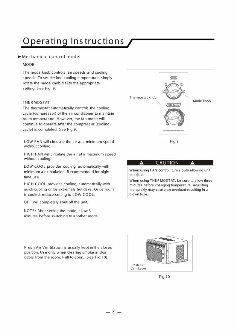
T hermostat knobMode knob
When us ing F AN control, turn s lowly allowing unitto adjust.
When us ing T HE R MOS T AT , be sure to allow threeminutes before changing temperature. Adjustingtoo quickly may cause an overload resulting in ablown fuse.
C A UT ION! !
MODE
F ig.9
T he mode knob controls fan speeds and coolingspeeds . To set des ired cooling temperature, s implyrotate the mode knob dial to the appropriatesetting. S ee F ig. 9.
L OW F A N will circulate the air at a minimum speedwithout cooling.
HIG H F A N will circulate the air at a maximum speedwithout cooling.
L OW C OOL provides cooling, automatically withminimum air circulation. R ecommended for night-time use.
HIG H C OOL provides cooling, automatically withquick cooling or for extremely hot days . Once room is cooled, reduce setting to L OW C OOL .
NOT E : After setting the mode, allow 3 minutes before switching to another mode.
OF F will completely shut-off the unit.
T HE R MOS T AT
T he thermostat automatically controls the cooling cycle (compressor) of the air conditioner to maintainroom temperature. However, the fan motor willcontinue to operate after the compressor (coolingcycle) is completed. S ee F ig.9.
Operating Ins truc tions
Mec hanic al c ontrol model
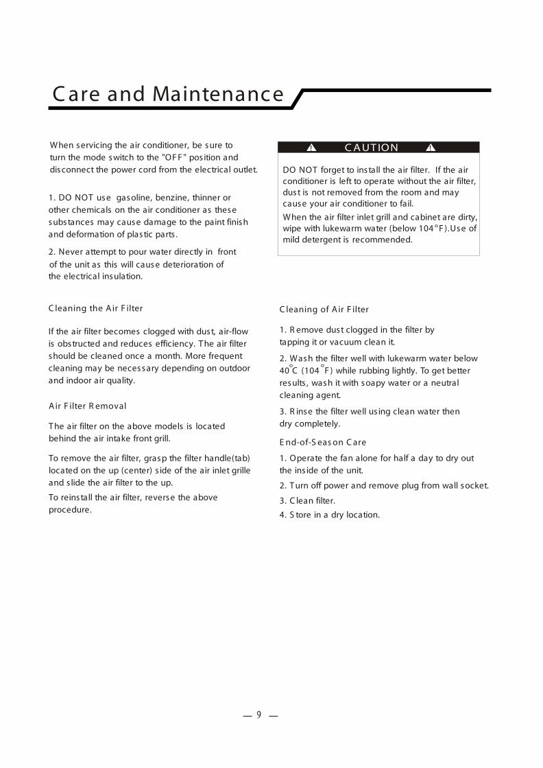
F ig.10
F resh Air V ent Lever
F res h A ir V entilation is usually kept in the closedposition. Use only when clearing smoke and/orodors from the room. P ull to open. (S ee F ig.10).
8
When servicing the air conditioner, be sure toturn the mode switch to the "OF F " pos ition anddisconnect the power cord from the electrical outlet.
1. DO NOT use gasoline, benzine, thinner or other chemicals on the air conditioner as thesesubstances may cause damage to the paint finishand deformation of plastic parts .
2. Never attempt to pour water directly in front
of the unit as this will cause deterioration ofthe electrical insulation.
C leaning the A ir F ilter
If the air filter becomes clogged with dust, air-flowis obstructed and reduces efficiency. T he air filtershould be cleaned once a month. More frequentcleaning may be necessary depending on outdoor and indoor air quality.
A ir F ilter R emoval
T he air filter on the above models is located behind the air intake front grill.
To remove the air filter, grasp the filter handle(tab) located on the up (center) s ide of the air inlet grilleand s lide the air filter to the up.
To reinstall the air filter, reverse the above procedure.
DO NOT forget to install the air filter. If the airconditioner is left to operate without the air filter,dust is not removed from the room and maycause your air conditioner to fail.
When the air filter inlet grill and cabinet are dirty, wipe with lukewarm water (below 104 F ).Use of mild detergent is recommended.
C leaning of A ir F ilter
1. R emove dust clogged in the filter bytapping it or vacuum clean it.
2. Wash the filter well with lukewarm water below40 C (104 F ) while rubbing lightly. To get betterresults , wash it with soapy water or a neutralcleaning agent.
3. R inse the filter well us ing clean water thendry completely.
E nd-of-S eas on C are
1. Operate the fan alone for half a day to dry outthe ins ide of the unit.
2. T urn off power and remove plug from wall socket.
3. C lean filter.
4. S tore in a dry location.
C A UT ION! !
C are and Maintenanc e
9
T roubles hooting G uide
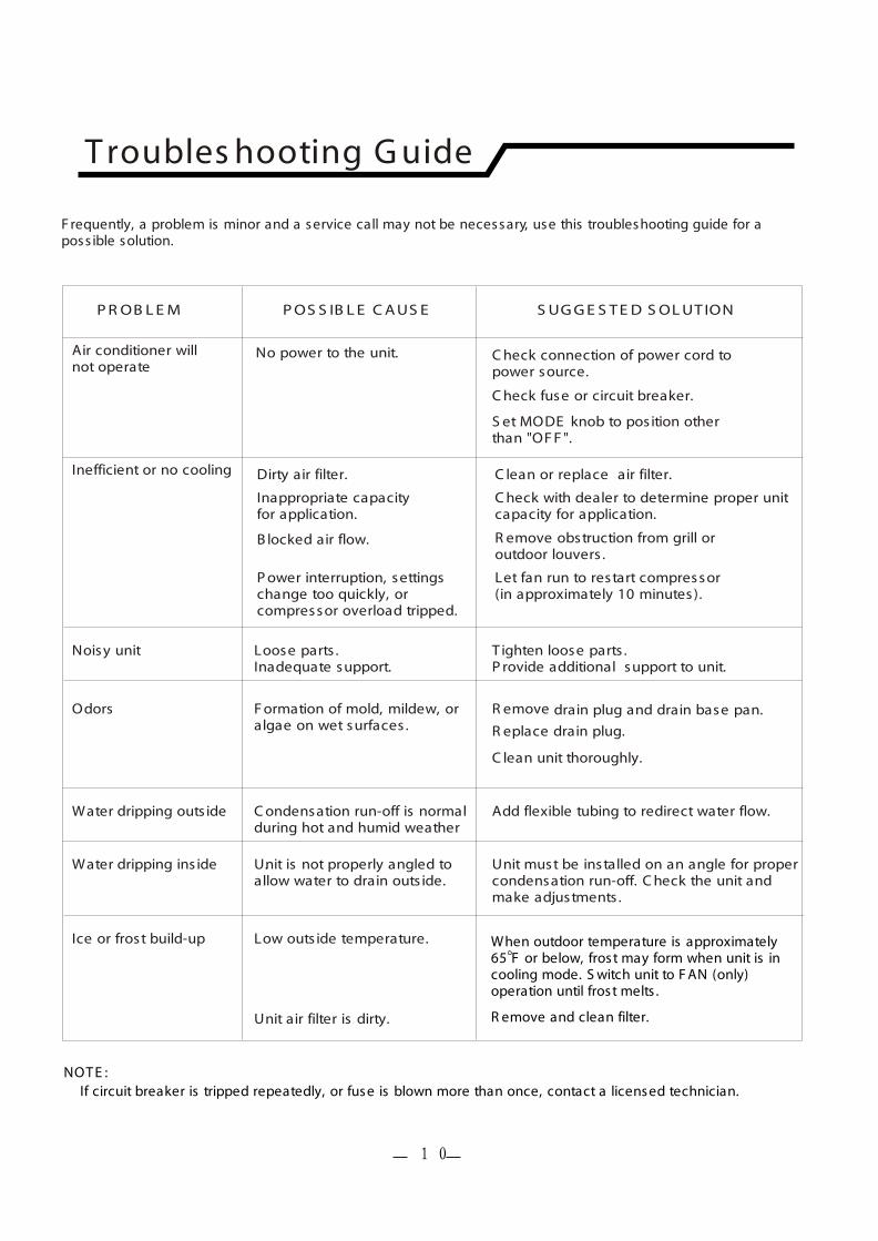
F requently, a problem is minor and a service call may not be necessary, use this troubleshooting guide for a poss ible solution.
When outdoor temperature is approximately 65 F or below, frost may form when unit is incooling mode. S witch unit to F AN (only) operation until frost melts .
R emove and clean filter.
NOT E : If circuit breaker is tripped repeatedly, or fuse is blown more than once, contact a licensed technician.
P R OB L E M P OS S IB L E C A US E S UG G E S T E D S OL UT ION
Air conditioner willnot operate
Inefficient or no cooling
Noisy unit
Odors
Water dripping outs ide
Water dripping ins ide
Ice or frost build-up Low outs ide temperature.
Unit air filter is dirty.
Unit is not properly angled toallow water to drain outs ide.
Unit must be installed on an angle for propercondensation run-off. C heck the unit andmake adjustments .
.
F ormation of mold, mildew, oralgae on wet surfaces .
C ondensation run-off is normalduring hot and humid weather
Add flexible tubing to redirect water flow.
drain plug and drain base pan.
R eplace drain plug.
C lean unit thoroughly.
R emove
Loose parts .Inadequate support.
T ighten loose parts .P rovide additional support to unit.
No power to the unit.
Dirty air filter.
Inappropriate capacityfor application.
B locked air flow.
P ower interruption, settingschange too quickly, orcompressor overload tripped.
C lean or replace air filter.
C heck with dealer to determine proper unitcapacity for application.
R emove obstruction from grill oroutdoor louvers .
Let fan run to restart compressor(in approximately 10 minutes).
C heck connection of power cord topower source.
C heck fuse or circuit breaker.
S et MODE knob to pos ition otherthan "OF F ".
10

© 2006 Sunbeam Products, Inc. doing business as Jarden Consumer Solutions. All rights reserved. Sunbeam® is a registered trademark of Sunbeam Products, Inc. used under license. Distributed by Petters Consumer Brands, LLC. 4400 Baker Road, Minnetonka, MN 55343.
For service, support and warranty information, visit www.sunbeammajorappliances.com or in the US call 1-866-866-6283.