user's manual - elhvb backup/manuals/slot_1...led anode (+) 3 4 led anode (+) led cathode (-)...
TRANSCRIPT

R-01-01-080514
6BXD
USER'S MANUAL
1. System power on by PS/2 Mouse: If you are using ATX powersupply, you are able to power on the system by doubleclicking the right or left button of your PS/2 Mouse.
2. System power on by Keyboard: If your ATX power supplysupports larger than 720 mA 5V Stand-By current, you canpower on your system by entering password from theKeyboard after setting the “Keyboard power on” jumper (JP1)and password in CMOS Setup.
3. Modem Ring-On on COM B.
4. Wake-Up on LAN. (The ATX power supply supports largerthan 600 mA)
5. Support 3 steps ACPI LED selectable.
Pentium II Processor MAINBOARD
REV. 1 First Edition

6BXD
1
The author assumes no responsibility for any errors or omissions which may
appear in this document nor does it make a commitment to update the
information contained herein.
Third-party brands and names are the property of their respectiveowners.
Sound Blaster is a registered trademark of Creative Technology Ltd in theUnited States and certain other countries. Sound Blaster-LINK and SB-LINKare trademarks of Creative Technology Ltd.
MAY 14, 1998 Taipei, Taiwan
Quick Installation Guide
2
I. Quick Installation Guide :
CPU SPEED SETUP
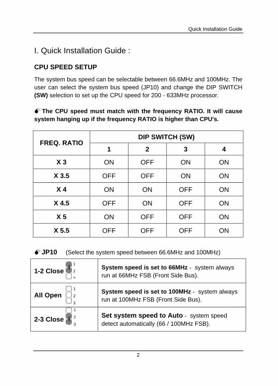
The system bus speed can be selectable between 66.6MHz and 100MHz. Theuser can select the system bus speed (JP10) and change the DIP SWITCH(SW) selection to set up the CPU speed for 200 - 633MHz processor.
MThe CPU speed must match with the frequency RATIO. It will causesystem hanging up if the frequency RATIO is higher than CPU's.
DIP SWITCH (SW)FREQ. RATIO
1 2 3 4
X 3 ON OFF ON ON
X 3.5 OFF OFF ON ON
X 4 ON ON OFF ON
X 4.5 OFF ON OFF ON
X 5 ON OFF OFF ON
X 5.5 OFF OFF OFF ON
MJP10 (Select the system speed between 66.6MHz and 100MHz)
1-2 Close System speed is set to 66MHz − system alwaysrun at 66MHz FSB (Front Side Bus).
All Open System speed is set to 100MHz − system alwaysrun at 100MHz FSB (Front Side Bus).
2-3 CloseSet system speed to Auto − system speeddetect automatically (66 / 100MHz FSB).
1
2
3
1
2
3
1
2
3
6BXD
3
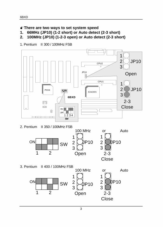
MThere are two ways to set system speed1. 66MHz (JP10) (1-2 short) or Auto detect (2-3 short)2. 100MHz (JP10) (1-2-3 open) or Auto detect (2-3 short)
1. Pentium II 300 / 100MHz FSB
CPU2
6BXD
CPU1
PIIX482443BX
JP10
2. Pentium II 350 / 100MHz FSB
3. Pentium II 400 / 100MHz FSB
SWON
1 2
SW
1 2
ON
Open
Open
JP10123
123
JP10
SW
ON
OFF
4321
Open
JP10123
JP10123
2-3Close
2-3
Close
JP10123
100 MHz or AutoDetect
100 MHz or AutoDetect
2-3
Close
JP10123
Quick Installation Guide
4
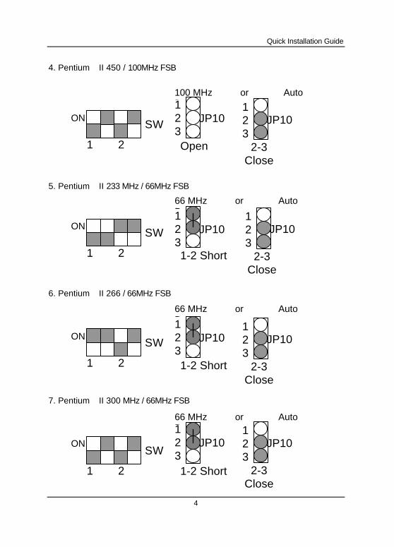
4. Pentium II 450 / 100MHz FSB
5. Pentium II 233 MHz / 66MHz FSB
6. Pentium II 266 / 66MHz FSB
7. Pentium II 300 MHz / 66MHz FSB
SWON
1 2
SWON
1 2
SWON
1 2
SWON
1 2
Open
1-2 Short
1-2 Short
1-2 Short
JP10123
JP10123
JP10123
JP10123
2-3
Close
JP10123
100 MHz or AutoDetect
66 MHz or AutoDetect
2-3
Close
JP10123
66 MHz or AutoDetect
2-3
Close
JP10123
2-3
Close
JP10123
66 MHz or AutoDetect
6BXD
5
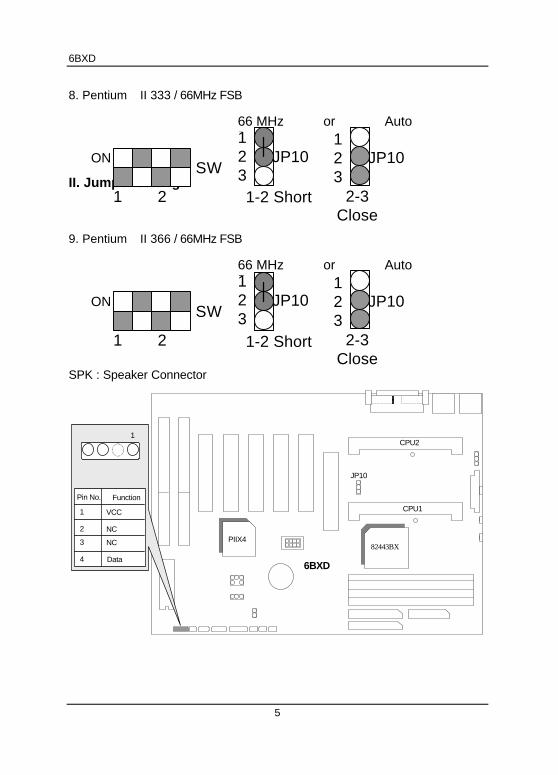
8. Pentium II 333 / 66MHz FSB
II. Jumper setting :
9. Pentium II 366 / 66MHz FSB
SPK : Speaker Connector
CPU2
6BXD
CPU1
PIIX482443BX
JP10
Pin No. Function
1
2
VCC
NC3
NC
4 Data
1
SWON
1 2 1-2 Short
JP10123
2-3Close
JP10123
66 MHz or AutoDetect
SWON
1 2
JP10123
2-3Close
JP10123
66 MHz or AutoDetect
1-2 Short
Quick Installation Guide
6
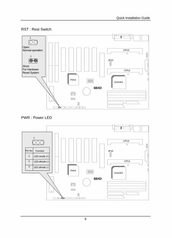
RST : Rest Switch
CPU2
6BXD
CPU1
PIIX482443BX
JP10
1
Open:Normal operation
Short:For HardwareReset System
1
PWR : Power LED
CPU2
6BXD
CPU1
PIIX482443BX
JP10
1
Pin No. Function
1
2
LED anode (+)
LED athode (-)3
LED athode (-)
6BXD
7
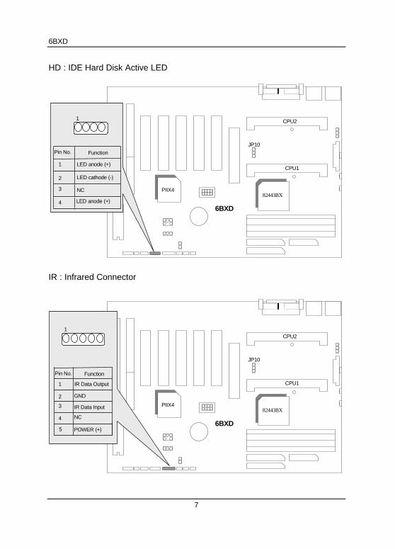
HD : IDE Hard Disk Active LED
CPU2
6BXD
CPU1
PIIX482443BX
JP10
1
Pin No. Function
1
2
LED anode (+)
3
4 LED anode (+)
LED cathode (-)
NC
IR : Infrared Connector
CPU2
6BXD
CPU1
PIIX482443BX
JP10
1
GND
IR Data Input
Pin No. Function
1
2
IR Data Output
3
4 NC
POWER (+)5
Quick Installation Guide
8
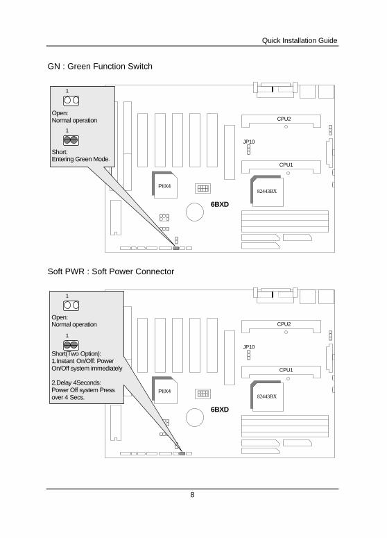
GN : Green Function Switch
CPU2
6BXD
CPU1
PIIX482443BX
JP10
1
Open:Normal operation
Short:Entering Green Mode.
1
Soft PWR : Soft Power Connector
CPU2
6BXD
CPU1
PIIX482443BX
JP10
1
Open:Normal operation
1
Short(Two Option):1.Instant On/Off: PowerOn/Off system immediately
2.Delay 4Seconds:Power Off system Pressover 4 Secs.
6BXD
9
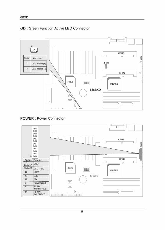
GD : Green Function Active LED Connector
CPU2
686BXD
CPU1
PIIX482443BX
JP10
1
Pin No. Function
1
2
LED anode (+)
LED athode (-)
POWER : Power Connector
CPU2
6BXD
CPU1
PIIX482443BX
JP10
1
VCC (+5V)
Power Good
Pin No. Function
4,6,19,20
GND
10
12
18
8
+12V
-12V
-5V
9
14 PS-ON(Soft ON/OFF)
5V SB(Stand by +5V)
13,15-173,5,7
Quick Installation Guide
10
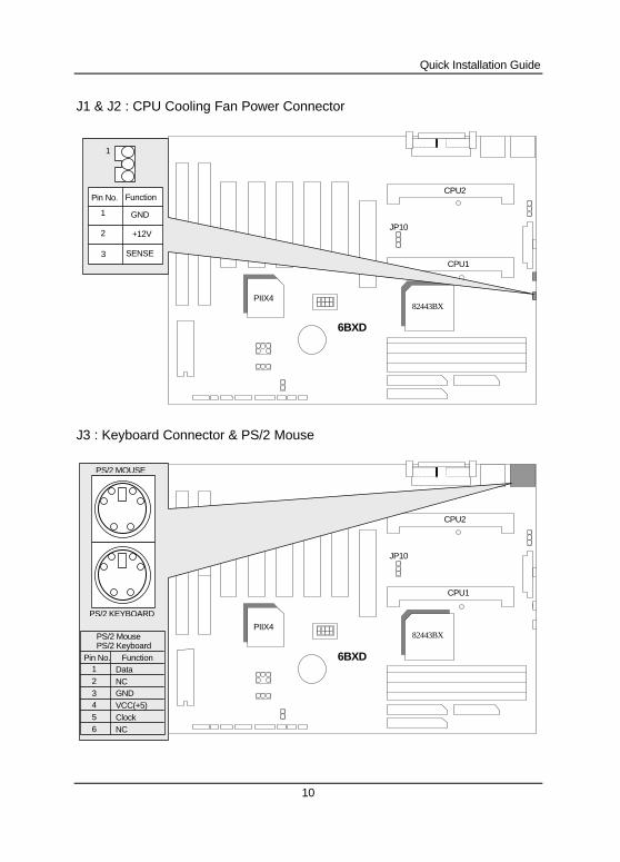
J1 & J2 : CPU Cooling Fan Power Connector
CPU2
6BXD
CPU1
PIIX482443BX
JP10
1
Pin No. Function
1
2
3
GND
+12V
SENSE
J3 : Keyboard Connector & PS/2 Mouse
CPU2
6BXD
CPU1
PIIX482443BX
JP10
Function
2
4
1
3
56
DataNC
VCC(+5)GND
NCClock
Pin No.
PS/2 Mouse
PS/2 MOUSE
PS/2 KEYBOARD
PS/2 Keyboard
6BXD
11
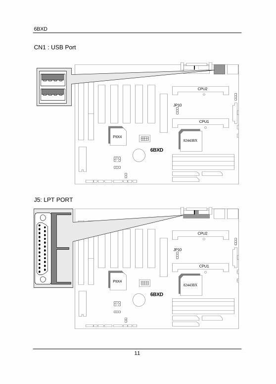
CN1 : USB Port
CPU2
6BXD
CPU1
PIIX482443BX
JP10
J5: LPT PORT
CPU2
6BXD
CPU1
PIIX482443BX
JP10
Quick Installation Guide
12
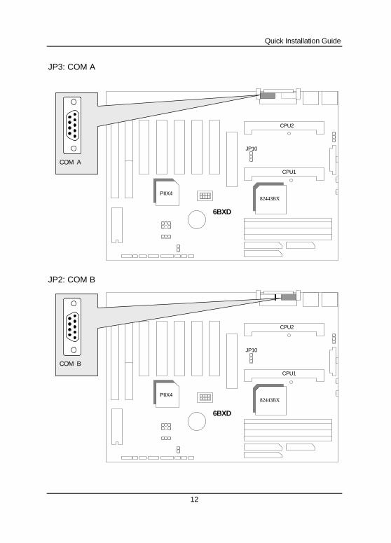
JP3: COM A
CPU2
6BXD
CPU1
PIIX482443BX
JP10
COM A
JP2: COM B
CPU2
6BXD
CPU1
PIIX482443BX
JP10
COM B
6BXD
13
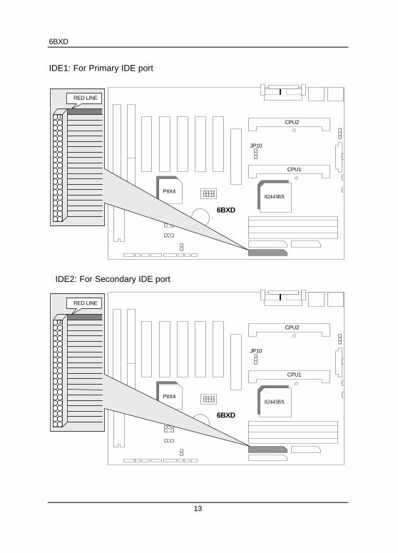
IDE1: For Primary IDE port
CPU2
6BXD
CPU1
PIIX482443BX
JP10
1
RED LINE
IDE2: For Secondary IDE port
CPU2
6BXD
CPU1
PIIX482443BX
JP10
1
RED LINE
Quick Installation Guide
14
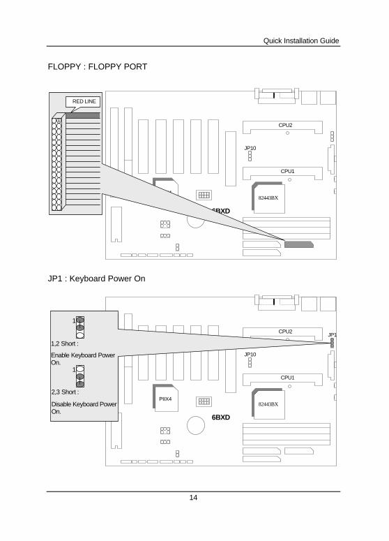
FLOPPY : FLOPPY PORT
CPU2
6BXD
CPU1
PIIX482443BX
JP10
1
RED LINE
JP1 : Keyboard Power On
CPU2
6BXD
CPU1
PIIX482443BX
JP10
2,3 Short :
Disable Keyboard PowerOn.
1,2 Short :
Enable Keyboard PowerOn.
1
1
JP1
6BXD
15
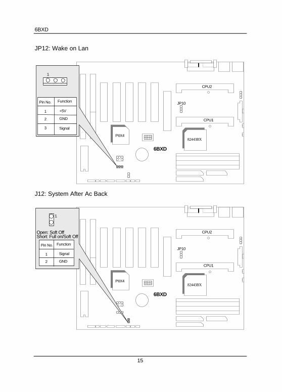
JP12: Wake on Lan
CPU2
6BXD
CPU1
PIIX482443BX
JP10Pin No. Function
1
2
3
GND
Signal
+5V
1
J12: System After Ac Back
CPU2
6BXD
CPU1
PIIX482443BX
JP10
1
Open: Soft OffShort: Full on/Soft Off
Pin No. Function
1
2 GND
Signal
Quick Installation Guide
16
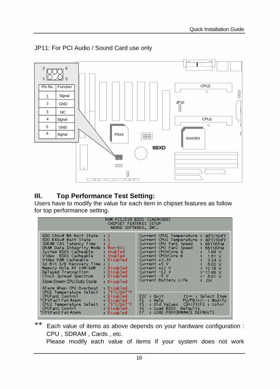
JP11: For PCI Audio / Sound Card use only
CPU2
6BXD
CPU1
PIIX482443BX
JP10
6
5
2
1
Pin No. Function
1
2 GND
Signal
3 NC
4 Signal
5 GND
6 Signal
III. Top Performance Test Setting:Users have to modify the value for each item in chipset features as followfor top performance setting.
** Each value of items as above depends on your hardware configuration :CPU , SDRAM , Cards , etc.Please modify each value of items If your system does not work

6BXD
17
properly .
6BXD
1
TABLE OF CONTENTS
1. INTRODUCTION
1.1. PREFACE................................................................................... 1-1
1.2. KEY FEATURES ......................................................................... 1-1
1.3. PERFORMANCE LIST ................................................................ 1-2
1.4. BLOCK DIAGRAM ...................................................................... 1-3
1.5. INTRODUCE THE Pentium II Processor ................................... 1-4
1.6. WHAT IS AGP?........................................................................... 1-6
2. SPECIFICATION
2.1. HARDWARE............................................................................... 2-1
2.2. SOFTWARE ............................................................................... 2-2
2.3. ENVIRONMENT.......................................................................... 2-2
3. HARDWARE INSTALLATION
3.1. UNPACKING............................................................................... 3-1
3.2. MAINBOARD LAYOUT................................................................ 3-2
3.3. QUICK REFERENCE FOR JUMPERS & CONNECTORS............ 3-2
3.4. DRAM INSTALLATION................................................................ 3-5
3.5. CPU SPEED SETUP................................................................... 3-6
3.6. CMOS RTC & ISA CFG CMOS SRAM......................................... 3-7
3.7. SPEAKER CONNECTOR INSTALLATION .................................. 3-7
3.8. HARDWARE RESET SWITCH CONNECTOR INSTALLATION ... 3-7
3.9. POWER LED CONNECTOR INSTALLATION.............................. 3-7
3.10. IDE & ATAPI DEVICE INSTALLATION ...................................... 3-8
3.12. PERIPHERAL DEVICE INSTALLATION .................................... 3-8
3.13. KEYBOARD & PS/2 MOUSE INSTALLATION........................... 3-8
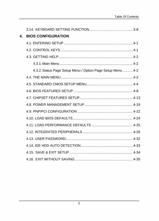
Table Of Contents
2
3.14. KEYBOARD SETTING FUNCTION ........................................... 3-8
4. BIOS CONFIGURATION
4.1. ENTERING SETUP..................................................................... 4-1
4.2. CONTROL KEYS ........................................................................ 4-1
4.3. GETTING HELP.......................................................................... 4-2
4.3.1.Main Menu......................................................................... 4-2
4.3.2.Status Page Setup Menu / Option Page Setup Menu .......... 4-2
4.4. THE MAIN MENU........................................................................ 4-2
4.5. STANDARD CMOS SETUP MENU.............................................. 4-4
4.6. BIOS FEATURES SETUP ........................................................... 4-8
4.7. CHIPSET FEATURES SETUP..................................................... 4-13
4.8. POWER MANAGEMENT SETUP ................................................ 4-19
4.9. PNP/PCI CONFIGURATION ....................................................... 4-22
4.10. LOAD BIOS DEFAULTS............................................................ 4-24
4.11. LOAD PERFORMANCE DEFAULTS ......................................... 4-25
4.12. INTEGRATED PERIPHERALS .................................................. 4-26
4.13. USER PASSWORD................................................................... 4-32
4.14. IDE HDD AUTO DETECTION.................................................... 4-33
4.15. SAVE & EXIT SETUP ............................................................... 4-34
4.16. EXIT WITHOUT SAVING.......................................................... 4-35

6BXD
1-1
1. INTRODUCTION
1.1. PREFACE
Welcome to use the 6BXD motherboard. The motherboard is a Dual
Pentium II Processor based PC / AT compatible system with AGP / PCI /ISA Bus, and has been designed to be the fastest PC / AT system. There aresome new features allow you to operate the system with just the performanceyou want.
This manual also explains how to install the motherboard for operation, andhow to set up your CMOS CONFIGURATION with BIOS SETUP program.
1.2. KEY FEATURES
q Intel Dual Pentium II Processor based PC / AT compatible mainboard.
q Dual Slot 1 on board supports dual Pentium II processor running at 200-633MHz.
q Intel 440BX chipset, Support AGP / SDRAM / Ultra DMA/33 IDE / ACPIfeatures.
q Support CPU FAN Failure / Overheat Alarm & auto slow down CPUspeed.
q Support PS/2 mouse & Keyboard Wake Up function.
q Support Intel LDCM Network Manageability.
q Support PCI Audio & Wake on Lan function.
q Supports 4xDIMMs using 3.3V EDO or SDRAM DIMM module.
q Supports 8 MB - 1 GB EDO / 1GB SDRAM memory on board.
q Supports ECC or Non-ECC type DRAM module.
q 1xAGP slot, 5xPCI Bus slots, 2xISA Bus slots.
q Supports 2 channels Ultra DMA/33 IDE ports for 4 IDE Devices.
q Supports 2xCOM (16550), 1xLPT (EPP / ECP), 1x1.44MB Floppy port.
q Supports 2xUSB ports, 1xPS/2 Mouse & 1xPS/2 Keyboard ports.
q Licensed AWARD BIOS, 2M bits FLASH RAM.
Introduction
1-2
q ATX form factor, Double stack I/O connector, 4 layers PCB.
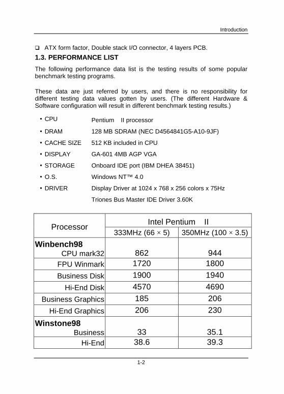
1.3. PERFORMANCE LIST
The following performance data list is the testing results of some popularbenchmark testing programs.
These data are just referred by users, and there is no responsibility fordifferent testing data values gotten by users. (The different Hardware &Software configuration will result in different benchmark testing results.)
• CPU Pentium II processor
• DRAM 128 MB SDRAM (NEC D4564841G5-A10-9JF)
• CACHE SIZE 512 KB included in CPU
• DISPLAY GA-601 4MB AGP VGA
• STORAGE Onboard IDE port (IBM DHEA 38451)
• O.S. Windows NT™ 4.0
• DRIVER Display Driver at 1024 x 768 x 256 colors x 75Hz
Triones Bus Master IDE Driver 3.60K
Intel Pentium IIProcessor
333MHz (66 × 5) 350MHz (100 × 3.5)
Winbench98CPU mark32 862 944
FPU Winmark 1720 1800
Business Disk 1900 1940
Hi-End Disk 4570 4690
Business Graphics 185 206
Hi-End Graphics 206 230
Winstone98Business 33 35.1
Hi-End 38.6 39.3
6BXD
1-3
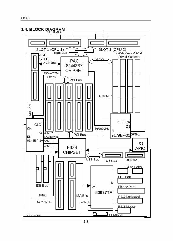
66/100MHz
8MHz
Floppy Port
3.3VEDO/SDRAMDIMM Sockets
1.4. BLOCK DIAGRAM
14.318MHz
IDE Bus
ISA Bus
AGPSLOT
SLOT 1 (CPU 2)
66MHzPCI Bus
PCI Bus
66/100MHz
LPT Port
USB #2
PS/2 Keyboard
COM Ports
USB #1
DRAM
PS/2 Mouse
USB Bus
SLOT 1 (CPU 1)
AGP Bus
Host Bus
PAC82443BXCHIPSET
I/O 83977TF
32.768KHz
48MHz
CLOCK GEN9148BF-10 33MHz
14.318MHz
33MHz
14.318MHz
CLOCK GEN9179BF-01
48MHzI/O
APICPIIX4CHIPSET
14.318MHz
33MHz
66/100MH
z
66/100MHz
Introduction
1-4
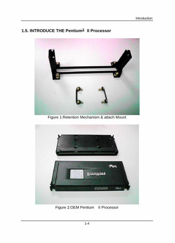
1.5. INTRODUCE THE Pentium II Processor
Figure 1:Retention Mechanism & attach Mount
Figure 2:OEM Pentium II Processor
6BXD
1-5
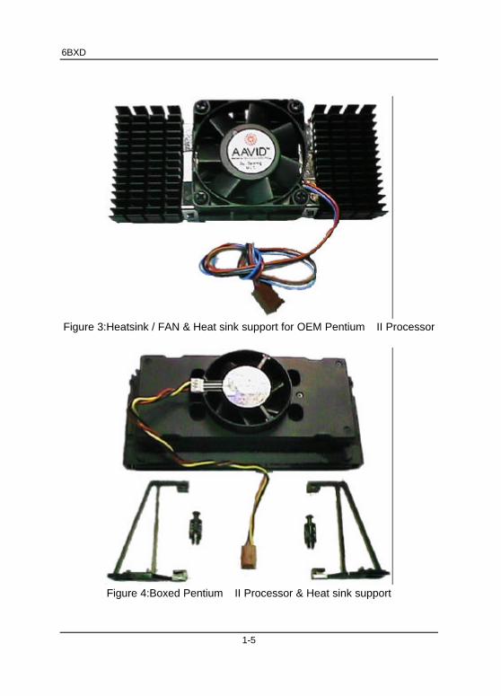
Figure 3:Heatsink / FAN & Heat sink support for OEM Pentium II Processor
Figure 4:Boxed Pentium II Processor & Heat sink support

Introduction
1-6
1.6. WHAT IS AGP?
The Accelerated Graphics Port (AGP) is a new port on the Host-To-PCIbridge device that supports an AGP port. The main purpose of the AGP portis to provide fast access to system memory.
The AGP port can be used either as fast PCI port (32-bits at 66MHz vs. 32-bits at 33MHz) or as an AGP port which supports 2x data-rate, a read queue,and side band addressing. When the 2x-data rate is used the port cantransmit data at 533Mb/sec (66.6*2*4). The read-queue can be used topipeline reads – removing the effects of the reads-latency. Side bandaddressing can be used to transmit the data address on a separate line inorder to further speed the transaction.
6BXD
2-1
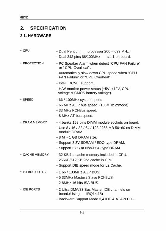
2. SPECIFICATION
2.1. HARDWARE
• CPU − Dual Pentium II processor 200 – 633 MHz.
− Dual 242 pins 66/100MHz slot1 on board.
• PROTECTION − PC Speaker Alarm when detect "CPU FAN Failure"or “ CPU Overheat” .
− Automatically slow down CPU speed when "CPUFAN Failure" or "CPU Overheat".
− Intel LDCM support.
− H/W monitor power status (±5V, ±12V, CPUvoltage & CMOS battery voltage).
• SPEED − 66 / 100MHz system speed.
− 66 MHz AGP bus speed. (133MHz 2*mode)
− 33 MHz PCI-Bus speed.
− 8 MHz AT bus speed.
• DRAM MEMORY − 4 banks 168 pins DIMM module sockets on board.
− Use 8 / 16 / 32 / 64 / 128 / 256 MB 50~60 ns DIMMmodule DRAM.
− 8 M ~ 1 GB DRAM size.
− Support 3.3V SDRAM / EDO type DRAM.
− Support ECC or Non-ECC type DRAM.
• CACHE MEMORY − 32 KB 1st cache memory included in CPU.
− 256KB/512 KB 2nd cache in CPU.
− Support DIB speed mode for L2 Cache.
• I/O BUS SLOTS − 1 66 / 133MHz AGP BUS.
− 5 33MHz Master / Slave PCI-BUS.
− 2 8MHz 16 bits ISA BUS.
• IDE PORTS − 2 Ultra DMA/33 Bus Master IDE channels onboard.(Using IRQ14,15)
− Backward Support Mode 3,4 IDE & ATAPI CD -
Specification
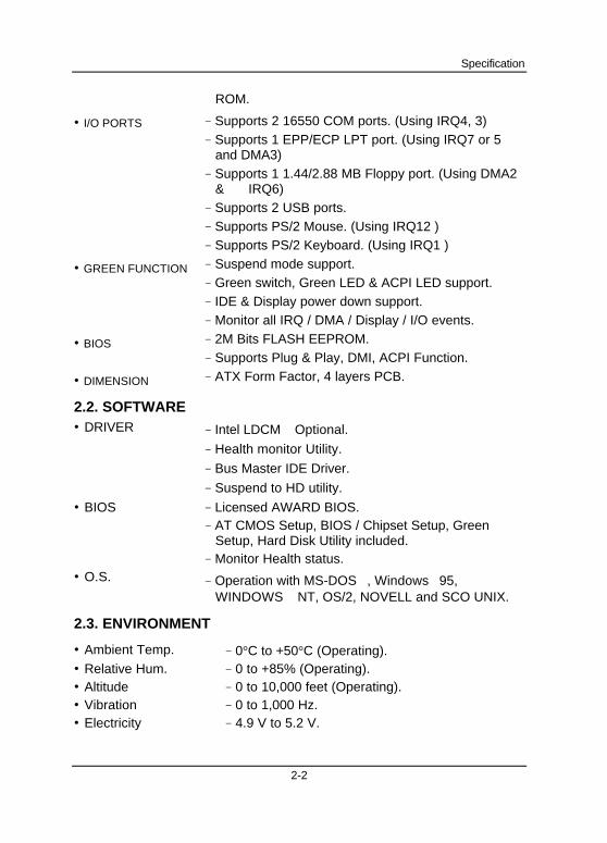
2-2
ROM.
• I/O PORTS − Supports 2 16550 COM ports. (Using IRQ4, 3)− Supports 1 EPP/ECP LPT port. (Using IRQ7 or 5
and DMA3)− Supports 1 1.44/2.88 MB Floppy port. (Using DMA2
& IRQ6)− Supports 2 USB ports.− Supports PS/2 Mouse. (Using IRQ12 )− Supports PS/2 Keyboard. (Using IRQ1 )
• GREEN FUNCTION − Suspend mode support.− Green switch, Green LED & ACPI LED support.− IDE & Display power down support.− Monitor all IRQ / DMA / Display / I/O events.
• BIOS − 2M Bits FLASH EEPROM.− Supports Plug & Play, DMI, ACPI Function.
• DIMENSION − ATX Form Factor, 4 layers PCB.
2.2. SOFTWARE• DRIVER − Intel LDCM Optional.
− Health monitor Utility.
− Bus Master IDE Driver.
− Suspend to HD utility.
• BIOS − Licensed AWARD BIOS.− AT CMOS Setup, BIOS / Chipset Setup, Green
Setup, Hard Disk Utility included.− Monitor Health status.
• O.S. − Operation with MS-DOS, Windows95,WINDOWS NT, OS/2, NOVELL and SCO UNIX.
2.3. ENVIRONMENT
• Ambient Temp. − 0°C to +50°C (Operating).• Relative Hum. − 0 to +85% (Operating).• Altitude − 0 to 10,000 feet (Operating).• Vibration − 0 to 1,000 Hz.• Electricity − 4.9 V to 5.2 V.

6BXD
2-3
− Max. 20A current at 5V.

6BXD
3-1
3. HARDWARE INSTALLATION
3.1. UNPACKING
The mainboard package should contain the following:
• The 6BXD mainboard.
• The Retention Mechanism & Attach Mount
• USER'S MANUAL for mainboard.
• Cable set for IDE¡ BFloppy device.
• Diskette or CD for Mainboard Utility Controller.
The mainboard contains sensitive electric components, which can be easilydamaged by static electricity, so the mainboard should be left in its originalpacking until it is installed.
Unpacking and installation should be done on a grounded anti-static mat.The operator should be wearing an anti static wristband, grounded at thesame point as the anti-static mat.
Inspect the mainboard carton for obvious damage. Shipping and handlingmay cause damage to your board. Be sure there are no shipping andhandling damages on the board before proceeding.
After opening the mainboard carton, extract the system board and place itonly on a grounded anti-static surface component side up. Again inspect theboard for damage. Press down on all of the socket IC's to make sure thatthey are properly seated. Do this only on with the board placed on a firm flatsurface.
MDO NOT APPLY POWER TO THE BOARD IF IT HAS BEEN DAMAGED.
You are now ready to install your mainboard. The mounting hole pattern onthe mainboard matches the ATX system board. It is assumed that thechassis is designed for a standard ATX mainboard mounting.
Place the chassis on the anti-static mat and remove the cover. Take the clips,stand-off and screws for mounting the system board, and keep them
Hardware Installation
3-2
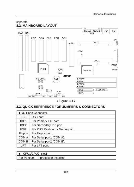
separate.3.2. MAINBOARD LAYOUT
CPU2
6BXD
CPU1
PIIX482443BX
JP10
USB PS/2
PCI5 PCI4 PCI3 PCI2 PCI1
AGP
ISA2 ISA1
BAT1
SW
SB-LINK
JP12J12
SPK REST HD IR GN GD
SOFTPWR
FLOPPY
IDE1
IDE2
BANK0BANK1BANK2BANK3
COMALPT
COMB
FAN2
FAN1
PWR1 1 1 1 1 1 1 1
JP1
×Figure 3.1Ø
3.3. QUICK REFERENCE FOR JUMPERS & CONNECTORS
t I/O Ports ConnectorUSB USB port.IDE1 For Primary IDE port.IDE2 For Secondary IDE port.PS/2 For PS/2 Keyboard / Mouse port.
Floppy For Floppy port.COM A For Serial port1 (COM A).COM B For Serial port2 (COM B).
LPT For LPT port.
t CPU1/CPU2: slot1For Pentium II processor installed.
6BXD
3-3
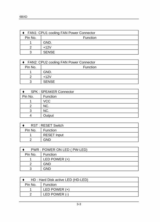
t FAN1: CPU1 cooling FAN Power ConnectorPin No. Function
1 GND.2 +12V3 SENSE
t FAN2: CPU2 cooling FAN Power ConnectorPin No. Function
1 GND.2 +12V3 SENSE
t SPK : SPEAKER ConnectorPin No. Function
1 VCC2 NC.3 NC.4 Output
t RST : RESET SwitchPin No. Function
1 RESET Input2 GND
t PWR : POWER ON LED ( PW-LED)Pin No. Function
1 LED POWER (+)2 GND3 GND
t HD : Hard Disk active LED (HD-LED)Pin No. Function
1 LED POWER (+)2 LED POWER (-)
Hardware Installation
3-4
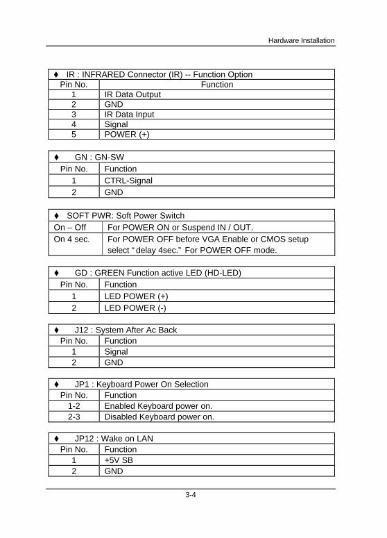
t IR : INFRARED Connector (IR) -- Function OptionPin No. Function
1 IR Data Output2 GND3 IR Data Input4 Signal5 POWER (+)
t GN : GN-SWPin No. Function
1 CTRL-Signal2 GND
t SOFT PWR: Soft Power SwitchOn – Off For POWER ON or Suspend IN / OUT.On 4 sec. For POWER OFF before VGA Enable or CMOS setup
select “ delay 4sec.” For POWER OFF mode.
t GD : GREEN Function active LED (HD-LED)Pin No. Function
1 LED POWER (+)2 LED POWER (-)
t J12 : System After Ac BackPin No. Function
1 Signal2 GND
t JP1 : Keyboard Power On SelectionPin No. Function
1-2 Enabled Keyboard power on.2-3 Disabled Keyboard power on.
t JP12 : Wake on LANPin No. Function
1 +5V SB2 GND
6BXD
3-5
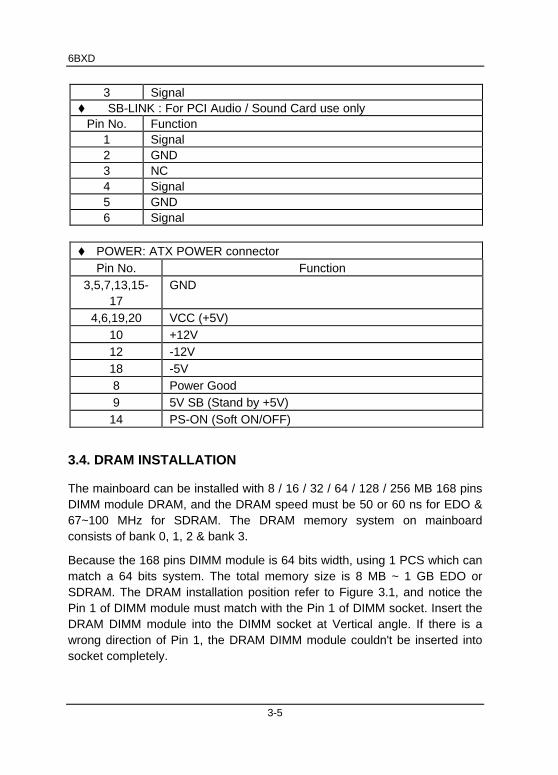
3 Signalt SB-LINK : For PCI Audio / Sound Card use only
Pin No. Function1 Signal2 GND3 NC4 Signal5 GND6 Signal
t POWER: ATX POWER connectorPin No. Function
3,5,7,13,15-17
GND
4,6,19,20 VCC (+5V)10 +12V12 -12V18 -5V8 Power Good9 5V SB (Stand by +5V)
14 PS-ON (Soft ON/OFF)
3.4. DRAM INSTALLATION
The mainboard can be installed with 8 / 16 / 32 / 64 / 128 / 256 MB 168 pinsDIMM module DRAM, and the DRAM speed must be 50 or 60 ns for EDO &67~100 MHz for SDRAM. The DRAM memory system on mainboardconsists of bank 0, 1, 2 & bank 3.
Because the 168 pins DIMM module is 64 bits width, using 1 PCS which canmatch a 64 bits system. The total memory size is 8 MB ~ 1 GB EDO orSDRAM. The DRAM installation position refer to Figure 3.1, and notice thePin 1 of DIMM module must match with the Pin 1 of DIMM socket. Insert theDRAM DIMM module into the DIMM socket at Vertical angle. If there is awrong direction of Pin 1, the DRAM DIMM module couldn't be inserted intosocket completely.
Hardware Installation
3-6
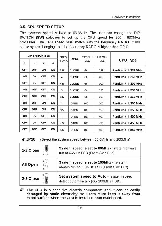
3.5. CPU SPEED SETUP
The system's speed is fixed to 66.6MHz. The user can change the DIPSWITCH (SW) selection to set up the CPU speed for 200 - 633MHzprocessor. The CPU speed must match with the frequency RATIO. It willcause system hanging up if the frequency RATIO is higher than CPU's.
DIP SWITCH (SW)
1 2 3 4
FREQ.
RATIOJP10
EXT.CLK.
MHz
INT.CLK.
MHz CPU Type
OFF OFF ON ON 3.5 CLOSE 66 233 Pentium II 233 MHz
ON ON OFF ON 4 CLOSE 66 266 Pentium II 266 MHz
OFF ON OFF ON 4.5 CLOSE 66 300 Pentium II 300 MHz
ON OFF OFF ON 5 CLOSE 66 333 Pentium II 333 MHz
OFF OFF OFF ON 5.5 CLOSE 66 366 Pentium II 366 MHz
ON OFF ON ON 3 OPEN 100 300 Pentium II 300 MHz
OFF OFF ON ON 3.5 OPEN 100 350 Pentium II 350 MHz
ON ON OFF ON 4 OPEN 100 400 Pentium II 400 MHz
OFF ON OFF ON 4.5 OPEN 100 450 Pentium II 450 MHz
OFF OFF OFF ON 5.5 OPEN 100 550 Pentium II 550 MHz
MJP10 (Select the system speed between 66.6MHz and 100MHz)
1-2 Close System speed is set to 66MHz − system alwaysrun at 66MHz FSB (Front Side Bus).
All Open System speed is set to 100MHz − systemalways run at 100MHz FSB (Front Side Bus).
2-3 CloseSet system speed to Auto − system speeddetect automatically (66/ 100MHz FSB).
M The CPU is a sensitive electric component and it can be easilydamaged by static electricity, so users must keep it away frommetal surface when the CPU is installed onto mainboard.
1
2
3
1
2
3
1
2
3

6BXD
3-7
3.6. CMOS RTC & ISA CFG CMOS SRAM
There're RTC & CMOS SRAM on board; they have a power supply fromexternal battery to keep the DATA inviolate & effective. The RTC is a REAL-TIME CLOCK device, which provides the DATE & TIME to system. TheCMOS SRAM is used for keeping the information of system configuration, sothe system can automatically boot OS. every time. Due to the life-time ofBattery internal battery is 5 years, the user can change a new Battery toreplace old one after it can not work.
M Danger of explosion if battery is incorrectly replaced.
M Replace only with the same or equivalent type recommended by themanufacturer.
M Dispose of used batteries according to the manufacturer’s instructions.
3.7. SPEAKER CONNECTOR INSTALLATION
There is always a speaker in AT system for sound purpose. The 4 - Pinsconnector J11 is used to connect speaker.
The speaker can work well in both direction of connector when it is installedto the connector J11 on mainboard.
3.8. HARDWARE RESET SWITCH CONNECTOR INSTALLATION
The RESET switch on panel provides users with HARDWARE RESETfunction, which is almost the same as power-on/off.
The system will do a cold start after the RESET switch is pushed andreleased by user. The RESET switch is a 2 PIN connector and should beinstalled to J10 on mainboard.
3.9. POWER LED CONNECTOR INSTALLATION
There are system power LED lamps on the panel of case. The power LEDwill light on when system is powered-on, which is connected to a 3 PINconnector.
The connector should be connected to JP7 of mainboard in correct direction.
Hardware Installation
3-8
3.10. IDE & ATAPI DEVICE INSTALLATION
There are two Enhance PCI IDE ports on board, which following ATAPIstandard SPEC. Any one IDE port can connected to two ATAPI devices (IDEHard Disk, CD-ROM & Tape Driver), so total four ATAPI devices can exist ina system.
The J7 is the active LED port for ATAPI device.
3.12. PERIPHERAL DEVICE INSTALLATION
After the I/O device installation and jumpers setup, the mainboard can bemounted into the case and fixed by screw.
To complete the mainboard installation, the peripheral device could beinstalled now. The basic system needs a display interface card.
If the PCI - Bus device is to be installed in the system, any one of five PCI -Bus slots can be used.
3.13. KEYBOARD & PS/2 MOUSE INSTALLATION
The main board supports PS/2 connector type keyboard & Mouse (J3).
The BIOS will auto detect whether the PS/2 Mouse is installed or nor &assign IRQ12 for Mouse port if which was installed.
After installing the peripheral device, the user should check everything again,and prepare to power-on the system.
3.14. KEYBOARD SETTING FUNCTION
After booting the O.S., there are some special functions used by keyboard asfollows:
"CTRL_ALT_DEL" − Pressing these keys simultaneously will cause
system to Warm Start (Software Reset).
6BXD
4-1
4. BIOS CONFIGURATION
Award's BIOS ROM has a built-in Setup program that allows users to modifythe basic system configuration. This type of information is stored in battery-backed CMOS SRAM so that it retains the Setup information when the poweris turned off.
4.1. ENTERING SETUP
Power ON the computer and press <Del> immediately will allow you to enterSetup. If the message disappears before you respond and you still wish toenter Setup, restart the system to try again by turning it OFF then ON orpressing the "RESET" bottom on the system case. You may also restart bysimultaneously press <Ctrl>, <Alt>, and <Del> keys.
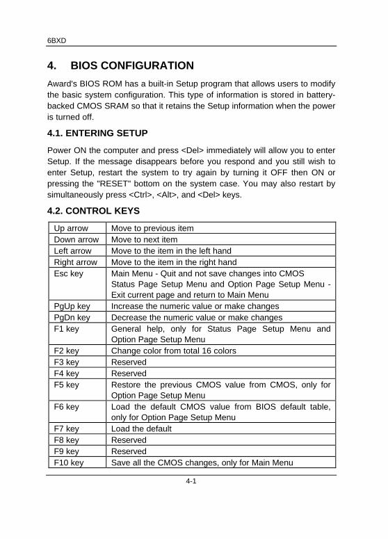
4.2. CONTROL KEYS
Up arrow Move to previous itemDown arrow Move to next itemLeft arrow Move to the item in the left handRight arrow Move to the item in the right handEsc key Main Menu - Quit and not save changes into CMOS
Status Page Setup Menu and Option Page Setup Menu -Exit current page and return to Main Menu
PgUp key Increase the numeric value or make changesPgDn key Decrease the numeric value or make changesF1 key General help, only for Status Page Setup Menu and
Option Page Setup MenuF2 key Change color from total 16 colorsF3 key ReservedF4 key ReservedF5 key Restore the previous CMOS value from CMOS, only for
Option Page Setup MenuF6 key Load the default CMOS value from BIOS default table,
only for Option Page Setup MenuF7 key Load the defaultF8 key ReservedF9 key ReservedF10 key Save all the CMOS changes, only for Main Menu
BIOS Configuration
4-2
4.3. GETTING HELP
4.3.1. Main Menu
The on-line description of the highlighted setup function is displayed at thebottom of the screen.
4.3.2. Status Page Setup Menu / Option Page Setup Menu
Press F1 to pop up a small help window that describes the appropriate keysto use and the possible selections for the highlighted item. To exit the HelpWindow press <Esc>.
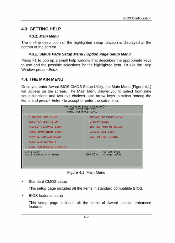
4.4. THE MAIN MENU
Once you enter Award BIOS CMOS Setup Utility, the Main Menu (Figure 4.1)will appear on the screen. The Main Menu allows you to select from ninesetup functions and two exit choices. Use arrow keys to select among theitems and press <Enter> to accept or enter the sub-menu.
Figure 4.1: Main Menu
• Standard CMOS setup
This setup page includes all the items in standard compatible BIOS.
• BIOS features setup
This setup page includes all the items of Award special enhancedfeatures.
6BXD
4-3
• Chipset features setup
This setup page includes all the items of chipset special features.
• Power management setup
This setup page includes all the items of Green function features.
• PNP/PCI configuration
This setup page includes all the configurations of PCI & PnP ISAresources.
• Load BIOS defaults
BIOS Defaults indicates the most appropriate value of the systemparameters that the system would be in safe configuration.
• Load Performance defaults
Performance Defaults indicates the value of the system parameters thatthe system would be in the best performance configuration.
• Integrated peripherals
This setup page includes all onboard peripherals.
• User password
Change, set, or disable password. It allows you to limit access to thesystem and Setup, or just to Setup.
• IDE HDD auto detection
Automatically configure hard disk parameters.
• Save & exit setup
Save CMOS value settings to CMOS and exit setup.
• Exit without saving
Abandon all CMOS value changes and exit setup.
BIOS Configuration
4-4
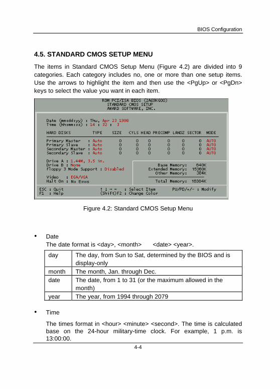
4.5. STANDARD CMOS SETUP MENU
The items in Standard CMOS Setup Menu (Figure 4.2) are divided into 9categories. Each category includes no, one or more than one setup items.Use the arrows to highlight the item and then use the <PgUp> or <PgDn>keys to select the value you want in each item.
Figure 4.2: Standard CMOS Setup Menu
• DateThe date format is <day>, <month> <date> <year>.
day The day, from Sun to Sat, determined by the BIOS and isdisplay-only
month The month, Jan. through Dec.date The date, from 1 to 31 (or the maximum allowed in the
month)year The year, from 1994 through 2079
• Time
The times format in <hour> <minute> <second>. The time is calculatedbase on the 24-hour military-time clock. For example, 1 p.m. is13:00:00.
6BXD
4-5
• Primary HDDs / Secondary HDDs
The category identifies the types of hard disk from drive C to F that hasbeen installed in the computer. There are two types: auto type, and userdefinable type. User type is user-definable; Auto type which willautomatically detect HDD type.
Note that the specifications of your drive must match with the drive table.The hard disk will not work properly if you enter improper information forthis category.
If you select User Type, related information will be asked to enter to thefollowing items. Enter the information directly from the keyboard andpress <Enter>. Such information should be provided in thedocumentation form your hard disk vendor or the system manufacturer.
CYLS. Number of cylindersHEADS number of headsPRECOMP write precompLANDZONE Landing zoneSECTORS number of sectors
If a hard disk has not been installed select NONE and press <Enter>.
• Drive A type / Drive B type
The category identifies the types of floppy disk drive A or drive B thathas been installed in the computer.
None No floppy drive installed360K, 5.25 in. 5.25 inch PC-type standard drive; 360K byte
capacity.1.2M, 5.25 in. 5.25 inch AT-type high-density drive; 1.2M byte
capacity (3.5 inch when 3 Mode is Enabled).720K, 3.5 in. 3.5 inch double-sided drive; 720K byte capacity1.44M, 3.5 in. 3.5 inch double-sided drive; 1.44M byte capacity.2.88M, 3.5 in. 3.5 inch double-sided drive; 2.88M byte capacity.
BIOS Configuration
4-6
• Floppy 3 Mode Support (for Japan Area)
Disabled Normal Floppy Drive.
Drive A Drive A is 3 mode Floppy Drive.
Drive B Drive B is 3 mode Floppy Drive.
Both Drive A & B are 3 mode Floppy Drives.
• Video
The category detects the type of adapter used for the primary systemmonitor that must match your video display card and monitor. Althoughsecondary monitors are supported, you do not have to select the type insetup.
EGA/VGA Enhanced Graphics Adapter/Video Graphics Array. ForEGA, VGA, SVGA, or PGA monitor adapters
CGA 40 Color Graphics Adapter, power up in 40 column mode
CGA 80 Color Graphics Adapter, power up in 80 column mode
MONO Monochrome adapter, includes high resolutionmonochrome adapters
• Halt on
The category determines whether the computer will stop if an error isdetected during power up.
NO Errors The system boot will not stop for any error thatmay be detected
All Errors Whenever the BIOS detects a non-fatal error thesystem will be stopped and you will be prompted
All, But Keyboard The system boot will not stop for a keyboarderror; it will stop for all other errors
All, But Diskette The system boot will not stop for a disk error; itwill stop for all other errors
All, But Disk/Key The system boot will not stop for a keyboard ordisk error; it will stop for all other errors
6BXD
4-7
• Memory
The category is display-only which is determined by POST (Power OnSelf Test) of the BIOS.
Base Memory
The POST of the BIOS will determine the amount of base (orconventional) memory installed in the system.
The value of the base memory is typically 512 K for systemswith 512 K memory installed on the motherboard, or 640 K forsystems with 640 K or more memory installed on themotherboard.
Extended Memory
The BIOS determines how much extended memory is presentduring the POST.
This is the amount of memory located above 1 MB in the CPU'smemory address map.
Expanded Memory
Expanded Memory in memory defined by theLotus/Intel/Microsoft (LIM) standard as EMS.Many standard DOS applications can not utilize memory above640 K; the Expanded Memory Specification (EMS) swapsmemory, which not utilized by DOS with a section, or frame, sothese applications, can access all of the system memory.
Memory can be swapped by EMS is usually 64 K within 1 MB ormemory above 1 MB, depends on the chipset design.
Expanded memory device driver is required to use memory asExpanded Memory.
Other Memory
This refers to the memory located in the 640 K to 1024 Kaddress space. This is memory that can be used for differentapplications.
DOS uses this area to load device drivers to keep as muchbase memory free for application programs. Most use for thisarea is Shadow RAM.
BIOS Configuration
4-8
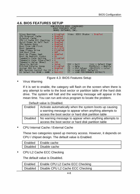
4.6. BIOS FEATURES SETUP
Figure 4.3: BIOS Features Setup• Virus Warning
If it is set to enable, the category will flash on the screen when there isany attempt to write to the boot sector or partition table of the hard diskdrive. The system will halt and the warning message will appear in themean time. You can run anti-virus program to locate the problem.
Default value is Disabled.Enabled Activate automatically when the system boots up causing
a warning message to appear when anything attempts toaccess the boot sector or hard disk partition table
Disabled No warning message to appear when anything attempts toaccess the boot sector or hard disk partition table
• CPU Internal Cache / External Cache
These two categories speed up memory access. However, it depends onCPU / chipset design. The default value is Enabled.
Enabled Enable cacheDisabled Disable cache
• CPU L2 Cache ECC Checking
The default value is Disabled.
Enabled Enable CPU L2 Cache ECC CheckingDisabled Disable CPU L2 Cache ECC Checking
6BXD
4-9
• Quick Power On Self Test
This category speeds up Power On Self Test (POST) after you power onthe computer. If it is set to Enable, BIOS will shorten or skip some checkitems during POST.
The default value is Enabled.
Enabled Enable quick POSTDisabled Normal POST
• CPU Update Data
The default value is Enabled.
Enabled Enable CPU Update DataDisabled Normal CPU Update Data
• Boot From LAN First
The default value is Enabled.
Enabled Enable Boot From LAN First FunctionDisabled Disable Boot From LAN First Function
• Boot Sequence
This category determines which drive computer searches first for thedisk operating system (i.e., DOS). Default value is A, C, SCSI.
X1, X2, X3 System will first search for X1 disk drive then X2 diskdrive and then X3 disk drive.
• Swap Floppy Drive
The default value is Disabled.
Enabled Floppy A & B will be swapped under DOSDisabled Floppy A & B will be normal definition
BIOS Configuration
4-10
• VGA Boot From
The default value is AGP.
AGP VGA Boot From AGPPCI VGA Boot From PCI
• Boot Up Floppy Seek
During POST, BIOS will determine the floppy disk drive installed is 40 or80 tracks. 360 K type is 40 tracks 720 K, 1.2 M and 1.44 M are all 80tracks. The default value is Enabled.
Enabled BIOS searches for floppy disk drive to determine it is 40 or80 tracks. Note that BIOS can not tell from 720 K, 1.2 M or1.44 M drive type as they are all 80 tracks
Disabled BIOS will not search for the type of floppy disk drive bytrack number. Note that there will not be any warningmessage if the drive installed is 360 K
• Boot Up NumLock Status
The default value is On.
On Keypad is number keysOff Keypad is arrow keys
• Typematic Rate Setting
The default value is Disabled.
Enabled Enable Keyboard Typematic rate setting.Disabled Disable Keyboard Typematic rate setting.
• Typematic Rate (Chars / Sec)
The default value is 6.
6-30 Set the maximum Typematic rate from 6 chars. Persecond to 30 chars. Per second.
• Typematic Delay (Msec)
The default value is 250.
250-1000 Set the time delay from first key to repeat the same key

6BXD
4-11
in to computer.
BIOS Configuration
4-12
• Security Option
This category allows you to limit access to the system and Setup, or justto Setup. The default value is Setup.
System The system can not boot and can not access to Setuppage will be denied if the correct password is not enteredat the prompt
Setup The system will boot, but access to Setup will be denied ifthe correct password is not entered at the prompt
M To disable security, select PASSWORD SETTING at Main Menu andthen you will be asked to enter password. Do not type anything andjust press <Enter>, it will disable security. Once the security isdisabled, the system will boot and you can enter Setup page freely.
• PCI/VGA Palette Snoop
The default value is Disabled.
Enabled For having Video Card on ISA Bus and VGA Card on PCI Bus.Disabled For VGA Card only.
• Assign IRQ For VGA
The default value is Enabled.
Enabled Assign a specific IRQ for VGADisabled No IRQ is assigned for VGA
• MPS Version control For OS
The default value is 1.1.
1.4 Enable MP spec. Ver.1.4.1.1 Enable MP spec. Ver.1.1.¡ ]for some OS., ie SCO
UNIX¡ ^
• OS Select For DRAM>64MB
The default value is Non-OS2.
Non-OS2 Using non-OS2 operating system.OS2 Using OS2 operating system and DRAM>64MB.
6BXD
4-13
• Video BIOS Shadow
It determines whether video BIOS is able to copy to RAM, however, it isoptional from chipset design. Video Shadow will increase the videospeed. The default value is Enabled.
Enabled Video shadow is enabledDisabled Video shadow is disabled
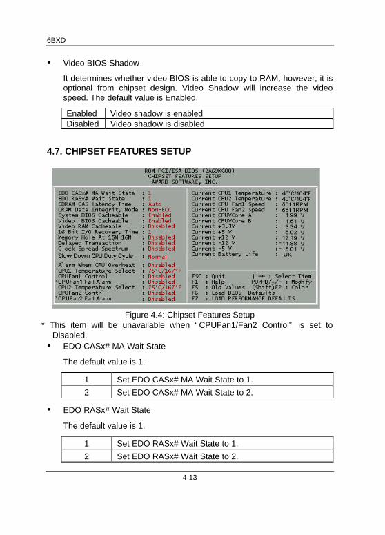
4.7. CHIPSET FEATURES SETUP
Figure 4.4: Chipset Features Setup* This item will be unavailable when “ CPUFan1/Fan2 Control” is set to
Disabled.• EDO CASx# MA Wait State
The default value is 1.
1 Set EDO CASx# MA Wait State to 1.
2 Set EDO CASx# MA Wait State to 2.
• EDO RASx# Wait State
The default value is 1.
1 Set EDO RASx# Wait State to 1.
2 Set EDO RASx# Wait State to 2.
BIOS Configuration
4-14
• SDRAM CAS latency Time
The default value is AUTO.
3 For 67 / 83 MHz SDRAM DIMM module.2 For 100 MHz SDRAM DIMM module.
Auto CAS latency time will be set automatically if you haveSPD on SDRAM
• DRAM Data Integrity Mode
The default value is Non-ECC.
Non-ECC For 64bit standard type DIMM module.ECC For 72bit ECC type DIMM module.
• System BIOS Cacheable
The default value is Enabled.
Enabled Enable System BIOS Cacheable.
Disabled Disable System BIOS Cacheable.
• Video BIOS Cacheable
The default value is Enabled.
Enabled Enable video BIOS Cacheable.
Disabled Disable video BIOS Cacheable.
• Video RAM Cacheable
The default value is Disabled.
Disabled Disable this function.Enabled Enable this function to get better VGA performance;
while some brands of VGA must be disabled thisfunction (e.g.ET4000W32P).
6BXD
4-15
• 16 Bit I/O Recovery Time
The default value is 1.
1-4 Set 16 Bit I/O recovery time from 1 to 4.NA None.
• Memory Hole At 15M-16M
The default value is Disabled.
Disabled Normal Setting.Enabled Set Address=15~16MB remap to ISA BUS.
• Delayed Transaction
The default value is Disabled.
Disabled Normal operation.Enabled For slow speed ISA device in system.
• Clock Spread Spectrum
The default value is Disabled.
Disabled Disabled this functionEnabled Enabled Clock Spread Spectrum
• Slow Down CPU Duty Cycle (Optional)
The default value is Normal.
Normal Disable Slow Down CPU Duty Cycle.12.5% Set Slow Down CPU Duty Cycle to 12.5%.25.0% Set Slow Down CPU Duty Cycle to 25.5%.37.5% Set Slow Down CPU Duty Cycle to 37.5%.50.0% Set Slow Down CPU Duty Cycle to 50.0%.62.5% Set Slow Down CPU Duty Cycle to 62.5%.75.0% Set Slow Down CPU Duty Cycle to 75.0%.
BIOS Configuration
4-16
• Alarm When CPU Overheat (Optional)
The default value is Disabled.
Disabled Disable this function.Enabled Alarm When the temperature of CPU exceeds the limit.
• CPU1 Temperature Select (Optional)
The default value is 75°C / 167°F.
65°C / 149°F Monitor CPU Temp. at 65°C / 149°F, if Temp. >65°C / 149°F will cause system alarming & slowdown CPU speed.
70°C / 158°F Monitor CPU Temp. at 70°C / 158°F, if Temp. >70°C / 158°F will cause system alarming & slowdown CPU speed.
75°C / 167°F Monitor CPU Temp. at 75°C / 167°F, if Temp. >75°C / 167°F will cause system alarming & slowdown CPU speed.
80°C / 176°F Monitor CPU Temp. at 80°C / 176°F, if Temp. >80°C / 176°F will cause system alarming & slowdown CPU speed.
85°C / 185°F Monitor CPU Temp. at 85°C / 185°F, if Temp. >85°C / 185°F will cause system alarming & slowdown CPU speed.
90°C / 194°F Monitor CPU Temp. at 90°C / 194°F, if Temp. >90°C / 194°F will cause system alarming & slowdown CPU speed.
95°C / 203°F Monitor CPU Temp. at 95°C / 203°F, if Temp. >95°C / 203°F will cause system alarming & slowdown CPU speed.
• CPUFan1 Control (Optional)
The default value is Disabled.
Disabled Disable this function.Enabled System will check the CPUAN1 status.
6BXD
4-17
• CPUFan1 Fail Alarm (Optional)
The default value is Disabled.
Disabled Disable this function.Enabled Alarm When CPUFAN Failed.
• CPU2 Temperature Select (Optional)
The default value is 75°C / 167°F.
65°C / 149°F Monitor CPU Temp. at 65°C / 149°F, if Temp. >65°C / 149°F will cause system alarming & slowdown CPU speed.
70°C / 158°F Monitor CPU Temp. at 70°C / 158°F, if Temp. >70°C / 158°F will cause system alarming & slowdown CPU speed.
75°C / 167°F Monitor CPU Temp. at 75°C / 167°F, if Temp. >75°C / 167°F will cause system alarming & slowdown CPU speed.
80°C / 176°F Monitor CPU Temp. at 80°C / 176°F, if Temp. >80°C / 176°F will cause system alarming & slowdown CPU speed.
85°C / 185°F Monitor CPU Temp. at 85°C / 185°F, if Temp. >85°C / 185°F will cause system alarming & slowdown CPU speed.
90°C / 194°F Monitor CPU Temp. at 90°C / 194°F, if Temp. >90°C / 194°F will cause system alarming & slowdown CPU speed.
95°C / 203°F Monitor CPU Temp. at 95°C / 203°F, if Temp. >95°C / 203°F will cause system alarming & slowdown CPU speed.
• CPUFan2 Control (Optional)
The default value is Disabled.
Disabled Disable this function.Enabled System will check the CPUAN2 status.
BIOS Configuration
4-18
• CPUFan2 Fail Alarm (Optional)
The default value is Disabled.
Disabled Disable this function.Enabled Alarm When CPUFAN2 Failed.
• Current CPU1 Temperature (Optional)
Detect CPU1 Temperature automatically.
• Current CPU2 Temperature (Optional)
Detect CPU2 Temperature automatically.
• Current CPU FAN1 Speed (Optional)
Detect CPU Fan1 speed status automatically.
• Current CPU FAN2 Speed (Optional)
Detect CPU Fan2 speed status automatically.
• Current CPU Vcore A / B ,+3.3V , ±12V , ±5V (Optional)
Detect system’s voltage status automatically.
• Current Battery Life (Optional)
The default value depends on system monitoring Battery status.
Fail The Battery (3V) voltage is out of SPEC.OK The Battery (3V) voltage is in SPEC.
6BXD
4-19
4.8. POWER MANAGEMENT SETUP
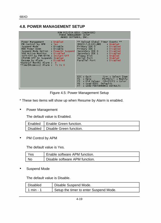
Figure 4.5: Power Management Setup
* These two items will show up when Resume by Alarm is enabled.
• Power Management
The default value is Enabled.
Enabled Enable Green function.Disabled Disable Green function.
• PM Control by APM
The default value is Yes.
Yes Enable software APM function.No Disable software APM function.
• Suspend Mode
The default value is Disable.
Disabled Disable Suspend Mode.1 min - 1 Setup the timer to enter Suspend Mode.
BIOS Configuration
4-20
Hour
• HDD Power Down
The default value is Disable.
Disable Disable HDD Power Down mode function.1-15 mins. Enable HDD Power Down mode between 1 to 15 mins.
• Suspend Mode Option (Optional)
The default value is PowerOn Suspend.
PowerOn Suspend Set the system to PowerOn Suspend modeSuspend to Disk Set the system to Suspend to Disk mode
• VGA Active Monitor
The default value is Disabled.
Disabled Disable monitor VGA activity.Enabled Enable monitor VGA activity.
• Soft-off by PWR-BTTN
The default value is Instant-Off.
Instant-off Soft switch ON/OFF for POWER ON/OFF.
Delay 4 Sec. Soft switch ON 4sec. for POWER OFF.
• CPUFAN Off In Suspend
The default value is Enabled.
Disabled Disable this function.Enabled Stop CPU FAN when entering Suspend mode.
• Resume by Alarm
The default value is Disabled.
Disabled Disable this function.Enabled Enable alarm function to POWER ON system.
If the “ Resume by Alarm” is Enabled.
Date ( of Month) Alarm : 0~31
6BXD
4-21
Time ( hh: mm: ss) Alarm : (0~23) : (0~59) : (0~59)
• IRQ [3-7,9-15] , NMI
The default value is Enabled.
Disabled Disable this function.Enabled Enable monitor IRQ [3-7,9-15] for Green event.
• Primary IDE 0/1
The default value is Disabled.
Disabled Disable this function.Enabled Enable monitor Primary IDE 0/1 for Green event.
• Secondary IDE 0/1
The default value is Disabled.
Disabled Disable this function.Enabled Enable monitor Secondary IDE 0/1 for Green event.
• Floppy Disk
The default value is Enabled.
Disabled Disable this function.Enabled Enable monitor Floppy Disk for Green event.
• Serial Port
The default value is Enabled.
Disabled Disable this function.
Enabled Enable monitor Serial Port for Green event.
• Parallel Port
The default value is Disabled.
Disabled Disable this function.
Enabled Enable monitor Parallel Port for Green event.
BIOS Configuration
4-22
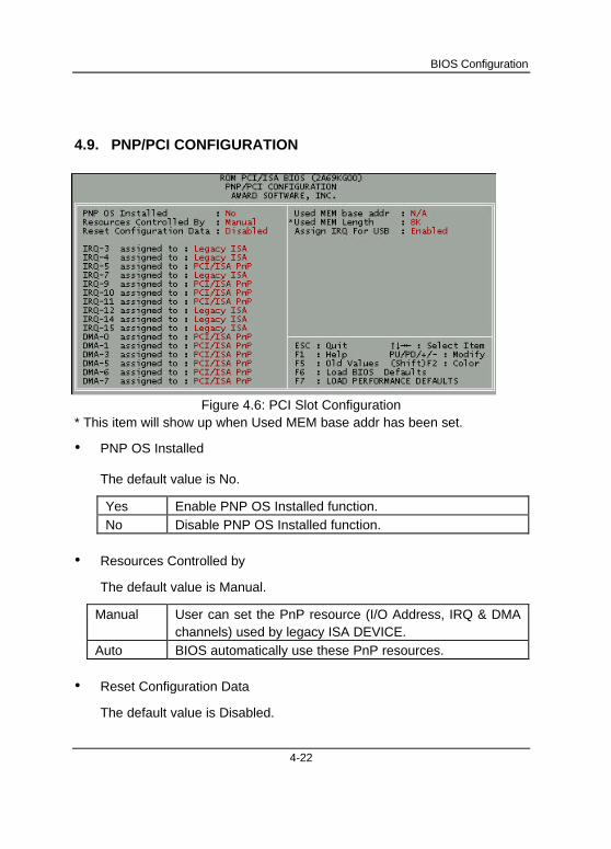
4.9. PNP/PCI CONFIGURATION
Figure 4.6: PCI Slot Configuration* This item will show up when Used MEM base addr has been set.
• PNP OS Installed
The default value is No.
Yes Enable PNP OS Installed function.No Disable PNP OS Installed function.
• Resources Controlled by
The default value is Manual.
Manual User can set the PnP resource (I/O Address, IRQ & DMAchannels) used by legacy ISA DEVICE.
Auto BIOS automatically use these PnP resources.
• Reset Configuration Data
The default value is Disabled.
6BXD
4-23
Disabled Disable this function.Enabled Enable clear PnP information in ESCD.
• IRQ (3,4,5,7,9,10,11,12,14,15), DMA(0,1,3,5,6,7) assigned to
The default value is "Legacy ISA" or "PCI/ISA PnP".
Legacy ISA The resource is used by Legacy ISA device.PCI/ISA PnP The resource is used by PCI/ISA PnP device (PCI or
ISA).
• Used MEM base addr
The default value is N/A.
N/A Disable the MEM. block using.C800 ~ DC00 Select the MEM. block starting address.
• Used MEM Length
The default value is 8K.
8K ~64K
Select the MEM. block size.
• Assign IRQ For USB
The default value is Enabled.
Enabled Assign a specific IRQ for USB
Disabled No IRQ is assigned for USB
BIOS Configuration
4-24
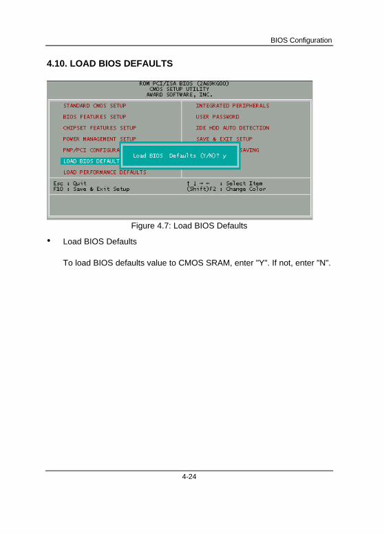
4.10. LOAD BIOS DEFAULTS
Figure 4.7: Load BIOS Defaults
• Load BIOS Defaults
To load BIOS defaults value to CMOS SRAM, enter "Y". If not, enter "N".
6BXD
4-25
4.11. LOAD PERFORMANCE DEFAULTS
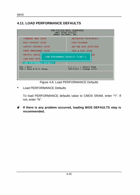
Figure 4.8: Load PERFORMANCE Defaults
• Load PERFORMANCE Defaults
To load PERFORMANCE defaults value to CMOS SRAM, enter "Y". Ifnot, enter "N".
M If there is any problem occurred, loading BIOS DEFAULTS step isrecommended.
BIOS Configuration
4-26
4.12. INTEGRATED PERIPHERALS
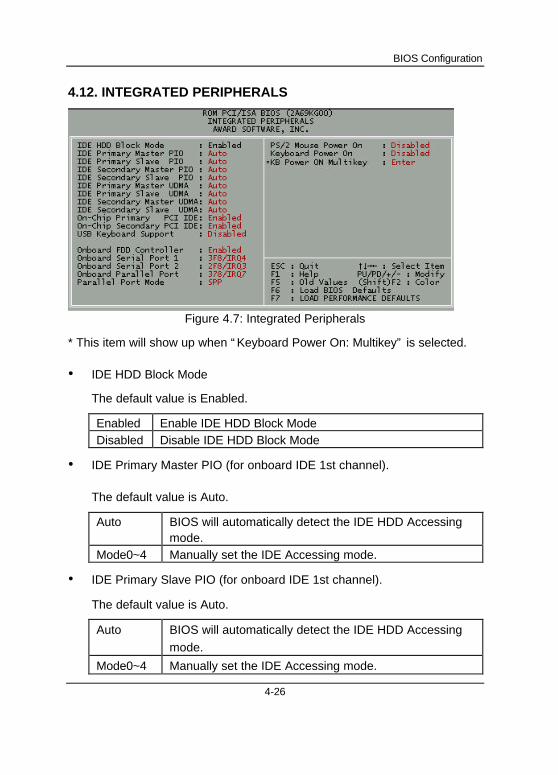
Figure 4.7: Integrated Peripherals
* This item will show up when “ Keyboard Power On: Multikey” is selected.
• IDE HDD Block Mode
The default value is Enabled.
Enabled Enable IDE HDD Block ModeDisabled Disable IDE HDD Block Mode
• IDE Primary Master PIO (for onboard IDE 1st channel).
The default value is Auto.
Auto BIOS will automatically detect the IDE HDD Accessingmode.
Mode0~4 Manually set the IDE Accessing mode.
• IDE Primary Slave PIO (for onboard IDE 1st channel).
The default value is Auto.
Auto BIOS will automatically detect the IDE HDD Accessing
mode.
Mode0~4 Manually set the IDE Accessing mode.
6BXD
4-27
• IDE Secondary Master PIO (for onboard IDE 2nd channel).
The default value is Auto.
Auto BIOS will automatically detect the IDE HDD Accessing
mode.
Mode0~4 Manually set the IDE Accessing mode.
• IDE Secondary Slave PIO (for onboard IDE 2nd channel).
The default value is Auto.
Auto BIOS will automatically detect the IDE HDD Accessing
mode.
Mode0~4 Manually set the IDE Accessing mode.
• IDE Primary Master UDMA.
The default value is Auto.
Auto BIOS will automatically detect the IDE HDD Accessing
mode.
Disabled Disable UDMA function.
• IDE Primary Slave UDMA.
The default value is Auto.
Auto BIOS will automatically detect the IDE HDD Accessing
mode.
Disabled Disable UDMA function.
• IDE Secondary Master UDMA.
The default value is Auto.
Auto BIOS will automatically detect the IDE HDD Accessingmode.
Disabled Disable UDMA function.
BIOS Configuration
4-28
• IDE Secondary Slave UDMA.
The default value is Auto.
Auto BIOS will automatically detect the IDE HDD Accessingmode.
Disabled Disable UDMA function.
• On-Chip Primary PCI IDE
The default value is Enabled.
Enabled Enable onboard 1st channel IDE port.Disabled Disable onboard 1st channel IDE port.
• On-Chip Secondary PCI IDE
The default value is Enabled.
Enabled Enable onboard 2nd channel IDE port.Disabled Disable onboard 2nd channel IDE port.
• USB Keyboard Support
The default value is Disabled.
Enabled Enable USB Keyboard Support.Disabled Disable USB Keyboard Support.
• Onboard FDD Controller
The default value is Enabled.
Enabled Enable onboard FDD port.Disabled Disable onboard FDD port.
• Onboard Serial Port 1
The default value is 3F8/IRQ4.
Auto BIOS will automatically setup the port 1 address.3F8/IRQ4 Enable onboard Serial port 1 and address is 3F8/IRQ4.2F8/IRQ3 Enable onboard Serial port 1 and address is 2F8/IRQ3.3E8/IRQ4 Enable onboard Serial port 1 and address is
3E8/IRQ4.2E8/IRQ3 Enable onboard Serial port 1 and address is

6BXD
4-29
2E8/IRQ3.Disabled Disable onboard Serial port 1.
• Onboard Serial Port 2
The default value is 2F8/IRQ3.
Auto BIOS will automatically setup the port 2 address.3F8/IRQ4 Enable onboard Serial port 2 and address is 3F8/IRQ4.2F8/IRQ3 Enable onboard Serial port 2 and address is 2F8/IRQ3.3E8/IRQ4 Enable onboard Serial port 2 and address is
3E8/IRQ4.2E8/IRQ3 Enable onboard Serial port 2 and address is
2E8/IRQ3.Disabled Disable onboard Serial port 2.
• Onboard Parallel port
The default value is 378/IRQ7.
378/IRQ7 Enable onboard LPT port and address is 378/IRQ7.
278/IRQ5 Enable onboard LPT port and address is 278/IRQ5.
Disabled Disable onboard LPT port.
3BC/IRQ7 Enable onboard LPT port and address is 3BC/IRQ7.
• Parallel Port Mode
The default value is SPP.
SPP Using Parallel port as Standard Printer Port.
EPP Using Parallel port as Enhanced Parallel Port.
ECP Using Parallel port as Extended Capabilities Port.
ECP/EPP Using Parallel port as ECP & EPP mode.
• PS/2 Mouse Power on
The default value is Disabled.
Disabled Disable PS/2 Mouse Power on .Left Double Click twice on PS/2 mouse left button to Power on system.

BIOS Configuration
4-30
Right Double Click twice on PS/2 mouse right button to Power onsystem.

6BXD
4-31
• Keyboard Power on
The default value is Disabled.
Disabled Disable Keyboard Power on .Multikey Enter multikey combination to Power on system.
• KB Power ON Multikey
EnterEnter from 1 to 8 characters to set the KeyboardPower On Password.
BIOS Configuration
4-32
4.13. USER PASSWORD
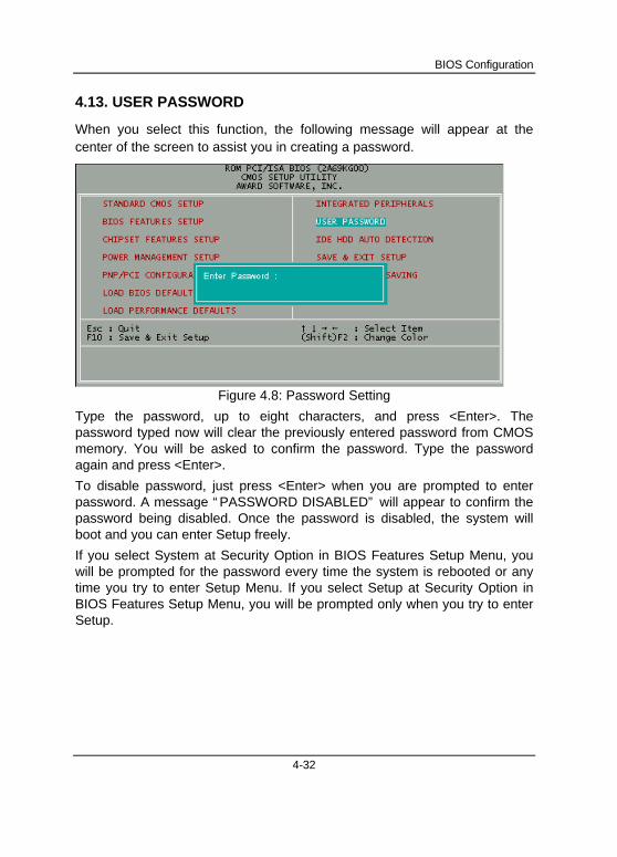
When you select this function, the following message will appear at thecenter of the screen to assist you in creating a password.
Figure 4.8: Password Setting
Type the password, up to eight characters, and press <Enter>. Thepassword typed now will clear the previously entered password from CMOSmemory. You will be asked to confirm the password. Type the passwordagain and press <Enter>.
To disable password, just press <Enter> when you are prompted to enterpassword. A message “ PASSWORD DISABLED” will appear to confirm thepassword being disabled. Once the password is disabled, the system willboot and you can enter Setup freely.
If you select System at Security Option in BIOS Features Setup Menu, youwill be prompted for the password every time the system is rebooted or anytime you try to enter Setup Menu. If you select Setup at Security Option inBIOS Features Setup Menu, you will be prompted only when you try to enterSetup.
6BXD
4-33
4.14. IDE HDD AUTO DETECTION
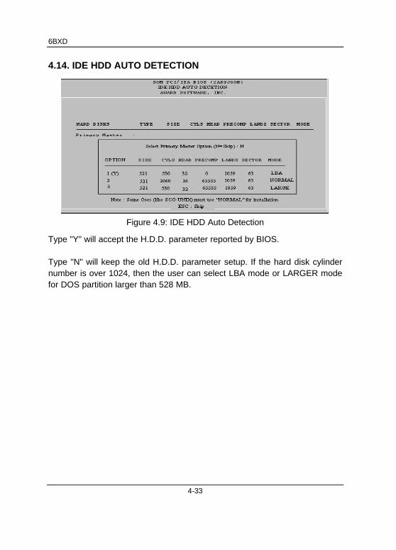
Figure 4.9: IDE HDD Auto Detection
Type "Y" will accept the H.D.D. parameter reported by BIOS.
Type "N" will keep the old H.D.D. parameter setup. If the hard disk cylindernumber is over 1024, then the user can select LBA mode or LARGER modefor DOS partition larger than 528 MB.
BIOS Configuration
4-34
4.15. SAVE & EXIT SETUP
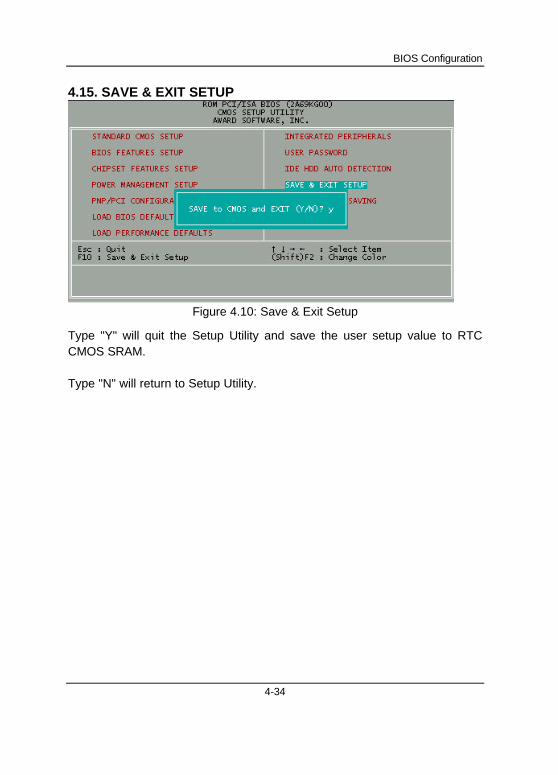
Figure 4.10: Save & Exit Setup
Type "Y" will quit the Setup Utility and save the user setup value to RTCCMOS SRAM.
Type "N" will return to Setup Utility.
6BXD
4-35
4.16. EXIT WITHOUT SAVING
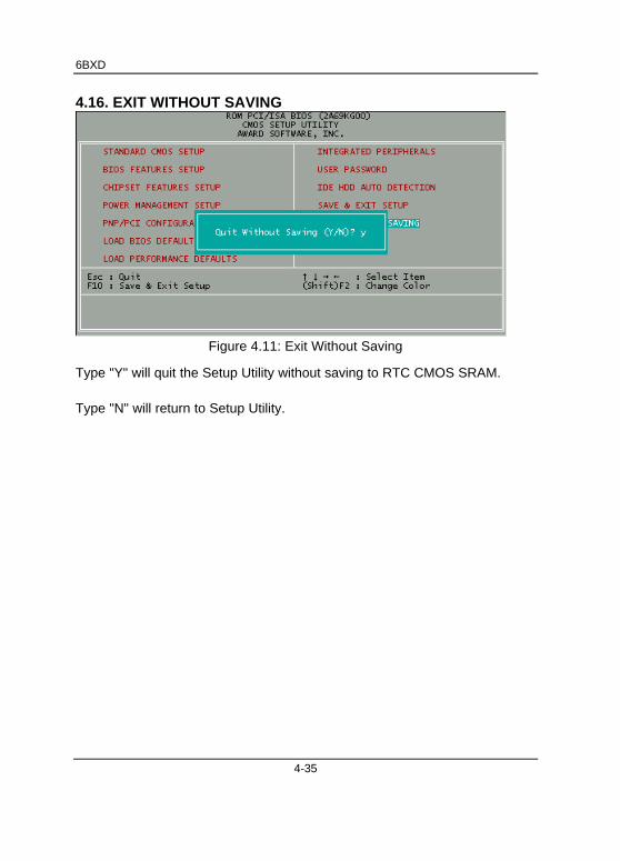
Figure 4.11: Exit Without Saving
Type "Y" will quit the Setup Utility without saving to RTC CMOS SRAM.
Type "N" will return to Setup Utility.

FCC Compliance Statement:This equipment has been tested and found to
comply with limits for a Class B digital device ,
pursuant to Part 15 of the FCC rules. These
limits are designed to provide reasonable
protection against harmful interference in
residential installations. This equipment
generates, uses, and can radiate radio
frequency energy, and if not installed and used
in accordance with the instructions, may
cause harmful interference to radio
communications. However, there is no
guarantee that interference will not occur in a particular installation. If this
equipment does cause interference to radio or television equipment reception,
which can be determined by turning the equipment off and on, the user is
encouraged to try to correct the interference by one or more of the following
measures:
-Reorient or relocate the receiving antenna
-Move the equipment away from the receiver
-Plug the equipment into an outlet on a circuit different from that to
which the receiver is connected
-Consult the dealer or an experienced radio/television technician for
additional suggestions
You are cautioned that any change or modifications to the equipment not
expressly approve by the party responsible for compliance could void Your
authority to operate such equipment.
This device complies with Part 15 of the FCC Rules. Operation is subjected
to the following two conditions 1) this device may not cause harmful
interference and 2) this device must accept any interference received,
DECLARATION OF CONFORMITYPer FCC Part 2 Section 2. 1077(a)
Responsible Party Name: G.B.T. INC.
Address: 18305 Valley Blvd., Suite#A
LA Puent, CA 91744
Phone/Fax No: (818) 854-9338/ (818) 854-9339
hereby declares that the product
Product Name:
Model Number:
Mother Board
GA-6BXD
Conforms to the following specifications:
FCC Part 15, Subpart B, Section 15.107(a) and Section 15.109(a),Class B Digital Device
Supplementary Information:
This device complies with part 15 of the FCC Rules. Operation is subject to thefollowing two conditions: (1) This device may not cause harmful interference,and (2) this device must accept any inference received, including interferencethat may cause undesired operation.
Representative Person's Name: ERIC LU
Signature:
Date: May. 13, 1998
Eric Lu

including interference that may cause undesired operation.

Declaration of ConformityWe, Manufacturer/Importer
(full address)
G.B.T. Technology Träding GMbHAusschlager Weg 41, 1F, 20537 Hamburg, Germany
declare that the product( description of the apparatus, system, installation to which it refers)
Mother BoardGA - 6BXD
is in conformity with(reference to the specification under which conformity is declared)
in accordance with 89/336 EEC-EMC Directive
EN 55011 Limits and methods of measurement Disturbances in supply systems caused racteristics of by household appliances and similar
industrial, scientific and medical (ISM r
“Harmonics
high frequency equipment
EN55013 EN61000-3-3*of radio disturbance characteristics of by household appliances and similarbroadcast receivers and associated electrical equipment “ Voltage fluctuations”equipment
EN 55014 Limits and methods of measurement EN 50081-1 Generic emission standard Part 1:of radio disturbance characteristics of Residual, commercial and light industryhousehold electrical appliances, portable tools and similar electrical EN 50082-1 Generic immunity standard Part 1:apparatus Residual, commercial and light industry
EN 55015 Limits and methods of measurement EN 55081-2 Generic emission standard Part 2:of radio disturbance characteristics of Industrial environmentfluorescent lamps and luminaries
EN 55020 Immunity from radio interference of EN 55082-2 Generic immunity standard Part 2:broadcast receivers and associated Industrial environmentequipment
EN 55022 Limits and methods of measurement ENV 55104 Immunity requirements for householdof radio disturbance characteristics of appliances tools and similar apparatusinformation technology equipment
DIN VDE 0855 Cabled distribution systems; Equipment EN 50091- 2 EMC requirements for uninterruptible part 10 for receiving and/or distribution from power systems (UPS) part 12 sound and television signals
CE marking (EC conformity marking)
with the actual required safety standards in accordance with LVD 73/23 EEC
EN 60065 EN 60950 Safety for information technology equipmentincluding electrical business equipment
household and simi
EN 60335 Safety of household and similar General and Safety requirements forelectrical appliances
Manufacturer/Importer
Signature : Rex Lin
(Stamp) Name Lin