user’s manual flir dm93
TRANSCRIPT

User’s manualFLIR DM93True RMS Industrial Multimeter

User’s manualFLIR DM93
#T559824; r. AL/33472/33472; en-US

Table of contents
1 Disclaimers. . . . . . . . . . . . . . . . . . . . . . . . . . . . . . . . . . . . . . . . . . . . . . . . . . . . . . . . . . . . . . 11.1 Copyright. . . . . . . . . . . . . . . . . . . . . . . . . . . . . . . . . . . . . . . . . . . . . . . . . . . . . . . 11.2 Quality assurance . . . . . . . . . . . . . . . . . . . . . . . . . . . . . . . . . . . . . . . . . . . . . 11.3 Documentation updates . . . . . . . . . . . . . . . . . . . . . . . . . . . . . . . . . . . . . . . 11.4 Disposal of electronic waste. . . . . . . . . . . . . . . . . . . . . . . . . . . . . . . . . . . 1
2 Safety information . . . . . . . . . . . . . . . . . . . . . . . . . . . . . . . . . . . . . . . . . . . . . . . . . . . . . . 22.1 FCC Compliance . . . . . . . . . . . . . . . . . . . . . . . . . . . . . . . . . . . . . . . . . . . . . . 52.2 Industry Canada compliance. . . . . . . . . . . . . . . . . . . . . . . . . . . . . . . . . . 6
3 Introduction . . . . . . . . . . . . . . . . . . . . . . . . . . . . . . . . . . . . . . . . . . . . . . . . . . . . . . . . . . . . . 73.1 Key features. . . . . . . . . . . . . . . . . . . . . . . . . . . . . . . . . . . . . . . . . . . . . . . . . . . . 7
4 Description . . . . . . . . . . . . . . . . . . . . . . . . . . . . . . . . . . . . . . . . . . . . . . . . . . . . . . . . . . . . . . 84.1 Meter description . . . . . . . . . . . . . . . . . . . . . . . . . . . . . . . . . . . . . . . . . . . . . . 84.2 Function switch . . . . . . . . . . . . . . . . . . . . . . . . . . . . . . . . . . . . . . . . . . . . . . . . 94.3 Function buttons . . . . . . . . . . . . . . . . . . . . . . . . . . . . . . . . . . . . . . . . . . . . . .104.4 Display description . . . . . . . . . . . . . . . . . . . . . . . . . . . . . . . . . . . . . . . . . . .114.5 Display icons and indicators . . . . . . . . . . . . . . . . . . . . . . . . . . . . . . . . .11
4.5.1 Probe indicator . . . . . . . . . . . . . . . . . . . . . . . . . . . . . . . . . . . . .134.5.2 Out-of-range warning . . . . . . . . . . . . . . . . . . . . . . . . . . . . . .13
5 Operation . . . . . . . . . . . . . . . . . . . . . . . . . . . . . . . . . . . . . . . . . . . . . . . . . . . . . . . . . . . . . . .145.1 Powering the meter . . . . . . . . . . . . . . . . . . . . . . . . . . . . . . . . . . . . . . . . . . .14
5.1.1 Auto power off. . . . . . . . . . . . . . . . . . . . . . . . . . . . . . . . . . . . . .145.2 Auto/Manual select mode . . . . . . . . . . . . . . . . . . . . . . . . . . . . . . . . . . . .145.3 Auto/Manual Range mode . . . . . . . . . . . . . . . . . . . . . . . . . . . . . . . . . . .155.4 Voltage measurements . . . . . . . . . . . . . . . . . . . . . . . . . . . . . . . . . . . . . . .165.5 Resistance measurements . . . . . . . . . . . . . . . . . . . . . . . . . . . . . . . . . . .165.6 Continuity test. . . . . . . . . . . . . . . . . . . . . . . . . . . . . . . . . . . . . . . . . . . . . . . . .175.7 Diode testing. . . . . . . . . . . . . . . . . . . . . . . . . . . . . . . . . . . . . . . . . . . . . . . . . .175.8 Capacitance measurements . . . . . . . . . . . . . . . . . . . . . . . . . . . . . . . . .185.9 Type K temperature measurements. . . . . . . . . . . . . . . . . . . . . . . . . .195.10 Current measurements . . . . . . . . . . . . . . . . . . . . . . . . . . . . . . . . . . . . . . .195.11 Extended functionality . . . . . . . . . . . . . . . . . . . . . . . . . . . . . . . . . . . . . . . .20
5.11.1 Selecting the mode . . . . . . . . . . . . . . . . . . . . . . . . . . . . . . . .205.11.2 VFD mode (ACV and ACA only) . . . . . . . . . . . . . . . . . . .215.11.3 Peak mode (ACV and ACA only) . . . . . . . . . . . . . . . . . .21
#T559824; r. AL/33472/33472; en-US v
Table of contents
5.11.4 Min/Max/Avg mode . . . . . . . . . . . . . . . . . . . . . . . . . . . . . . . .215.11.5 Frequency mode (ACV and ACA only) . . . . . . . . . . . .225.11.6 Relative mode. . . . . . . . . . . . . . . . . . . . . . . . . . . . . . . . . . . . . .225.11.7 dBm mode (ACVonly) . . . . . . . . . . . . . . . . . . . . . . . . . . . . .225.11.8 Manual Data Recording mode. . . . . . . . . . . . . . . . . . . . .225.11.9 Automatic Data Recording mode. . . . . . . . . . . . . . . . . .235.11.10 Setup mode . . . . . . . . . . . . . . . . . . . . . . . . . . . . . . . . . . . . . . . .255.11.11 Silent mode . . . . . . . . . . . . . . . . . . . . . . . . . . . . . . . . . . . . . . . .25
5.12 Normal hold mode and Auto hold mode . . . . . . . . . . . . . . . . . . . . .265.12.1 Normal hold mode . . . . . . . . . . . . . . . . . . . . . . . . . . . . . . . . .265.12.2 Auto hold mode . . . . . . . . . . . . . . . . . . . . . . . . . . . . . . . . . . . .26
5.13 Locked mode . . . . . . . . . . . . . . . . . . . . . . . . . . . . . . . . . . . . . . . . . . . . . . . . .265.14 Streaming measurement data using Bluetooth . . . . . . . . . . . . . .27
5.14.1 General . . . . . . . . . . . . . . . . . . . . . . . . . . . . . . . . . . . . . . . . . . . . .275.14.2 Procedure . . . . . . . . . . . . . . . . . . . . . . . . . . . . . . . . . . . . . . . . . .27
6 Maintenance. . . . . . . . . . . . . . . . . . . . . . . . . . . . . . . . . . . . . . . . . . . . . . . . . . . . . . . . . . . .286.1 Cleaning and storage. . . . . . . . . . . . . . . . . . . . . . . . . . . . . . . . . . . . . . . . .286.2 Battery replacement . . . . . . . . . . . . . . . . . . . . . . . . . . . . . . . . . . . . . . . . . .286.3 Fuse replacement . . . . . . . . . . . . . . . . . . . . . . . . . . . . . . . . . . . . . . . . . . . .286.4 Disposal of electronic waste. . . . . . . . . . . . . . . . . . . . . . . . . . . . . . . . . .28
7 Technical specifications . . . . . . . . . . . . . . . . . . . . . . . . . . . . . . . . . . . . . . . . . . . . . .297.1 General specifications. . . . . . . . . . . . . . . . . . . . . . . . . . . . . . . . . . . . . . . .297.2 Electrical specifications . . . . . . . . . . . . . . . . . . . . . . . . . . . . . . . . . . . . . .30
8 Technical support for external meters . . . . . . . . . . . . . . . . . . . . . . . . . . . . . .379 Warranties . . . . . . . . . . . . . . . . . . . . . . . . . . . . . . . . . . . . . . . . . . . . . . . . . . . . . . . . . . . . . .38
9.1 FLIR Global Limited Lifetime Warranty . . . . . . . . . . . . . . . . . . . . . .389.2 FLIR Test and Measurement Limited 2 Year
Warranty . . . . . . . . . . . . . . . . . . . . . . . . . . . . . . . . . . . . . . . . . . . . . . . . . . . . . .39
#T559824; r. AL/33472/33472; en-US vi

1 Disclaimers
1.1 Copyright© 2016, FLIR Systems, Inc. All rights reserved worldwide.No parts of the software including source code may be re-produced, transmitted, transcribed or translated into anylanguage or computer language in any form or by anymeans, electronic, magnetic, optical, manual or otherwise,without the prior written permission of FLIR Systems.
The documentation must not, in whole or part, be copied,photocopied, reproduced, translated or transmitted to anyelectronic medium or machine readable form without priorconsent, in writing, from FLIR Systems.
Names and marks appearing on the products herein areeither registered trademarks or trademarks of FLIR Sys-tems and/or its subsidiaries. All other trademarks, tradenames or company names referenced herein are used foridentification only and are the property of their respectiveowners.
1.2 Quality assuranceThe Quality Management System under which theseproducts are developed and manufactured has been certi-fied in accordance with the ISO 9001 standard.
FLIR Systems is committed to a policy of continuous de-velopment; therefore we reserve the right to makechanges and improvements on any of the products with-out prior notice.
1.3 Documentation updatesOur manuals are updated several times per year, and wealso issue product-critical notifications of changes on aregular basis.
To access the latest manuals and notifications, go to theDownload tab at:
http://support.flir.com
It only takes a few minutes to register online. In the down-load area you will also find the latest releases of manualsfor our other products, as well as manuals for our historicaland obsolete products.
1.4 Disposal of electronic waste
As with most electronic products, this equipment must bedisposed of in an environmentally friendly way, and in ac-cordance with existing regulations for electronic waste.
Please contact your FLIR Systems representative formore details.
#T559824; r. AL/33472/33472; en-US 1
2 Safety information
NOTE
Before operating the device, you must read, understand, and follow all instruc-tions, dangers, warnings, cautions, and notes.
Note FLIR Systems reserves the right to discontinue models, parts or accesso-ries, and other items, or to change specifications at any time without prior notice.
NOTE
Remove the batteries if the device is not used for an extended period of time.
WARNING
Do not operate the device if you do not have the correct knowledge. Formalqualifications and/or national legislation for the electrical inspections can ap-ply. Incorrect operation of the device can cause damage, shock, injury ordeath to persons.
WARNING
Do not start the measuring procedure before you have set the function switchto the correct position. This can cause damage to the instrument and cancause injury to persons.
WARNING
Do not change to current or resistance when you measure the voltage. Thiscan cause damage to the instrument and can cause injury to persons.
WARNING
Do not apply more than 1000 V between the terminals or between a terminaland the earth ground. This can cause damage to the instrument and injury topersons.
#T559824; r. AL/33472/33472; en-US 2
2 Safety information
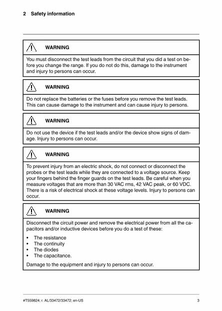
WARNING
You must disconnect the test leads from the circuit that you did a test on be-fore you change the range. If you do not do this, damage to the instrumentand injury to persons can occur.
WARNING
Do not replace the batteries or the fuses before you remove the test leads.This can cause damage to the instrument and can cause injury to persons.
WARNING
Do not use the device if the test leads and/or the device show signs of dam-age. Injury to persons can occur.
WARNING
To prevent injury from an electric shock, do not connect or disconnect theprobes or the test leads while they are connected to a voltage source. Keepyour fingers behind the finger guards on the test leads. Be careful when youmeasure voltages that are more than 30 VAC rms, 42 VAC peak, or 60 VDC.There is a risk of electrical shock at these voltage levels. Injury to persons canoccur.
WARNING
Disconnect the circuit power and remove the electrical power from all the ca-pacitors and/or inductive devices before you do a test of these:
• The resistance• The continuity• The diodes• The capacitance.
Damage to the equipment and injury to persons can occur.
#T559824; r. AL/33472/33472; en-US 3
2 Safety information
WARNING
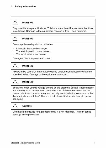
Only use this equipment indoors. This instrument is not for permanent outdoorinstallations. Damage to the equipment can occur if you use it outdoors.
WARNING
Do not apply a voltage to the unit when:
• It is not in the specified range• The switch position is not correct• The input value is not correct.
Damage to the equipment can occur.
WARNING
Always make sure that the protective rating of a function is not more than thespecified value. Damage to the equipment can occur.
WARNING
Be careful when you do voltage checks on the electrical outlets. These checksare not easy to do because you cannot be sure of the connection to the re-cessed electrical contacts. You must not only use this device to make sure thatthe terminals are not “live”. There is a risk of electrical shock. Injury to personcan occur.
CAUTION
Do not use the device for a procedure that it is not made for. This can causedamage to the protection.
#T559824; r. AL/33472/33472; en-US 4

2 Safety information
This symbol, adjacent to another symbol or terminal, indicates thatthe user must refer to the manual for further information.
This symbol, adjacent to a terminal, indicates that, under normaluse, hazardous voltages may be present.
Double insulation.
UL listing is not an indication or a verification of the accuracy of themeter
2.1 FCC Compliance
This device complies with part 15 of the FCC Rules. Operation is subject to thefollowing two conditions:
1. This device may not cause harmful interference.2. This device must accept any interference received, including interference
that may cause undesired operation.
This equipment has been tested and found to comply with the limits for a Class Bdigital device, pursuant to part 15 of the FCC Rules. These limits are designed toprovide reasonable protection against harmful interference in a residential instal-lation. This equipment generates, uses, and can radiate radio frequency energyand, if not installed and used in accordance with the instructions, may causeharmful interference to radio communications. However, there is no guaranteethat interference will not occur in a particular installation. If this equipment doescause harmful interference to radio or television reception, which can be deter-mined by turning the equipment off and on, the user is encouraged to try to cor-rect the interference by one or more of the following measures:
• Reorient or relocate the receiving antenna.• Increase the separation between the equipment and receiver.• Connect the equipment into an outlet on a circuit different from that to which
the receiver is connected.• Consult the dealer or an experienced radio/TV technician for help.
#T559824; r. AL/33472/33472; en-US 5

2 Safety information
CAUTION
Exposure to Radio Frequency Radiation.
To comply with FCC/IC RF exposure compliance requirements, a separationdistance of at least 20 cm must be maintained between the antenna of this de-vice and all persons. This device must not be co-located or operating in con-junction with any other antenna or transmitter.
WARNING
Changes or modifications not expressly approved by the party responsible forcompliance could void the user's authority to operate the equipment.
2.2 Industry Canada compliance
This device complies with Industry Canada licence-exempt RSS standard(s). Op-eration is subject to the following two conditions: (1) this device may not cause in-terference, and (2) this devicemust accept any interference, includinginterference that may cause undesired operation of thedevice.
CAUTION
Exposure to Radio Frequency Radiation.
To comply with RSS 102 RF exposure compliance requirements, for mobileconfigurations, a separation distance of at least 20 cm must be maintained be-tween the antenna of this device and all persons. This device must not be co-located or operating in conjunction with any other antenna or transmitter.
#T559824; r. AL/33472/33472; en-US 6

3 Introduction
Thank you for choosing a FLIR DM93 digital multimeter.
This device is shipped fully tested and calibrated and, with proper use, will pro-vide years of reliable service.
3.1 Key features
• 4000/40 000 counts extra-large digital dual display.• Auto selection AC/DC in voltage and current modes.• On-screen menu selection and navigator key drive.• Variable-frequency drive mode (low-pass filter).• 0.05% DCV accuracy.• Low-Z measurement.• Auto hold.• Peak hold measurement.• dB/dBm measurement.• 20,000-record automatic data recording capacity.• 99-record manual data record/recall memory.• 3 m drop tested and IP54 rated.• Dual display shows two measurements simultaneously.• METERLiNK® compatibility embeds electrical measurements into thermal
images captured by METERLiNK®-enabled FLIR infrared cameras.• Bluetooth connection to iOS and Android devices for remote viewing in hard-
to-reach and hazardous areas and downloading of data.• Safety category rating: CAT IV-600V, CAT III-1000V.
#T559824; r. AL/33472/33472; en-US 7

4 Description
4.1 Meter description
Figure 4.1 Front view
1. LCD display.2. Function buttons, see section 4.3 Function buttons, page 10.3. Selector pad.4. Function switch, see section 4.2 Function switch, page 9.5. Probe input terminals.
#T559824; r. AL/33472/33472; en-US 8

4 Description
Figure 4.2 Rear view
1. Probe clips.2. Tilt stand.3. Work light.4. Battery compartment cover.
4.2 Function switch
The meter can measure voltage through the probe inputs. A low-impedance load is placed across the inputs to stabilize themeasurement.
The meter is in full power-saving mode.
The meter can measure high voltage (V) through the probe inputs.
The meter can measure low voltage (mV) through the probeinputs.
#T559824; r. AL/33472/33472; en-US 9

4 Description
The meter can measure resistance, continuity, or diode polaritythrough the probe inputs. The type of measurement is selected bythe button.
The meter can measure capacitance through the probe inputs ortemperature through a thermocouple adapter. The type of meas-urement is selected by the button.
The meter can measure current through the probe inputs.
4.3 Function buttons
• Use the button to select Auto select or Manual select mode,see section 5.2 Auto/Manual select mode, page 14.
• In Manual select mode, press the button to change the operat-ing mode.
• Use the button to select Auto range or Manual range mode,see section 5.3 Auto/Manual Range mode, page 15.
• In Manual range mode, press the button to change the range(scale).
• Press the button to toggle between Normal and Hold mode,see section 5.12 Normal hold mode and Auto hold mode, page26.
• Press and hold the button for 5 seconds to enable/disableLocked mode, see section 5.13 Locked mode, page 26.
Use the selector pad to enable extended functionality modes andto navigate in mode options.
Press the button to exit an extended functionality mode.
#T559824; r. AL/33472/33472; en-US 10

4 Description
• Press the button to enable/disable the display backlight.• Press and hold the button for 2 seconds to enable/disable the
work light.
Press the button to enable/disable METERLiNK® (Bluetooth)communication, see section 5.14 Streaming measurement datausing Bluetooth, page 27.
4.4 Display description
1. Secondary display.2. Main display.3. Bar graph (matches the reading on the main display).
4.5 Display icons and indicators
Indicates that the meter is measuring stabilized voltage.
Indicates that the measured voltage is greater than 30 V (AC orDC).
Indicates that the Auto select mode is active.
Indicates that the meter is displaying maximum reading values.
Indicates that the meter is displaying minimum reading values.
Indicates that the meter is displaying the average reading.
Indicates that the meter is displaying peak maximum values.
#T559824; r. AL/33472/33472; en-US 11
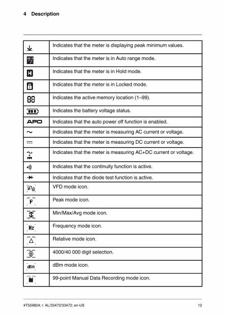
4 Description
Indicates that the meter is displaying peak minimum values.
Indicates that the meter is in Auto range mode.
Indicates that the meter is in Hold mode.
Indicates that the meter is in Locked mode.
Indicates the active memory location (1–99).
Indicates the battery voltage status.
Indicates that the auto power off function is enabled.
Indicates that the meter is measuring AC current or voltage.
Indicates that the meter is measuring DC current or voltage.
Indicates that the meter is measuring AC+DC current or voltage.
Indicates that the continuity function is active.
Indicates that the diode test function is active.
VFD mode icon.
Peak mode icon.
Min/Max/Avg mode icon.
Frequency mode icon.
Relative mode icon.
4000/40 000 digit selection.
dBm mode icon.
99-point Manual Data Recording mode icon.
#T559824; r. AL/33472/33472; en-US 12
4 Description
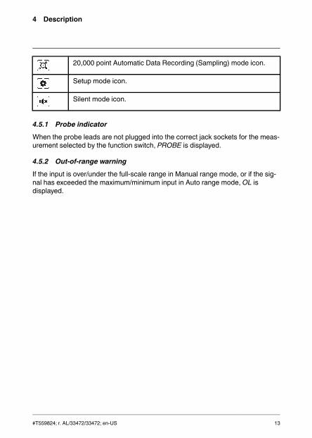
20,000 point Automatic Data Recording (Sampling) mode icon.
Setup mode icon.
Silent mode icon.
4.5.1 Probe indicator
When the probe leads are not plugged into the correct jack sockets for the meas-urement selected by the function switch, PROBE is displayed.
4.5.2 Out-of-range warning
If the input is over/under the full-scale range in Manual range mode, or if the sig-nal has exceeded the maximum/minimum input in Auto range mode, OL isdisplayed.
#T559824; r. AL/33472/33472; en-US 13

5 Operation
NOTE
Before operating the device, you must read, understand, and follow all instruc-tions, dangers, warnings, cautions, and notes.
NOTE
When the meter is not in use, the function switch should be set to theposition.
NOTE
When connecting the probe leads to the device under test, connect the nega-tive lead before connecting the positive lead. When removing the probe leads,remove the positive lead before removing the negative lead.
5.1 Powering the meter
1. Set the function switch to any position to switch on the meter.2. If the battery indicator shows that the battery voltage is low or if the me-
ter does not power on, replace the battery. See section 6.2 Battery replace-ment, page 28.
5.1.1 Auto power off
The meter enters sleep mode after a programmable number of minutes of inactiv-ity, see section 5.11.10 Setup mode, page 25.
The meter beeps three times 10 seconds before powering off. Press any buttonor turn the function switch to prevent the meter from powering off. The auto poweroff time-out is then reset.
5.2 Auto/Manual select mode
In Auto select mode, the meter attempts to automatically select the proper oper-ating mode based on the input signal:
#T559824; r. AL/33472/33472; en-US 14
5 Operation
If the function switch is set to the , , , or position, the meter attempts todetermine if the AC or DC mode should be used.
Auto select mode is the default mode of operation. When a new function is se-
lected with the function switch, the starting mode is Auto select and the indi-cator is displayed.
To enter Manual select mode, press the button. To manually select the op-erating mode, press the button repeatedly.
To enter Auto select mode, press and hold the button until the indicatoris displayed.
NOTE
Note that the DM93 Data Recording feature cannot be used when the meter isin the Auto Select Mode. To use the Data Recorder please set the meter tothe Manual Select mode first.
5.3 Auto/Manual Range mode
In Auto Range mode, the meter automatically selects the most appropriate meas-urement scale. In Manual Range mode, the desired range (scale) is set manually.
When Auto Range is the default mode of operation, for a given function selected
by the function switch, the indicator is displayed.
To switch to Manual Range mode from Auto Range mode, press the but-
ton momentarily. The indicator will switch off and the button can thenbe used to step through the available ranges manually.
To switch to Auto Range mode from Manual Range mode, press and hold the
button until the meter beeps and displays the indicator.
To switch to Auto Range mode from Auto Sense mode, press the button.
#T559824; r. AL/33472/33472; en-US 15

5 Operation
5.4 Voltage measurements
1. Set the function switch to one of the following positions:
• for high voltage measurements.• for low voltage measurements.• for voltage measurements using the meter's low input impedance
mode. The indicator is displayed.
2. Insert the black probe lead into the negative terminal and the red probelead into the positive terminal.
3. Use the button to select AC, DC, or AC+DC voltage measurement.
• The indicator will be displayed for AC measurements.• The indicator will be displayed for DC measurements.
• The indicator will be displayed for AC+DC measurements.
4. Connect the probe leads in parallel to the part under test.5. Read the voltage value on the display.
5.5 Resistance measurements
WARNING
Do not do diode, resistance, or continuity tests before you remove the powerfrom the capacitors and the other devices (when you do a test during a meas-urement). Injury to persons can occur.
1. Set the function switch to the position.2. Ensure that the meter is set to resistance measurement. The Ω unit will be
displayed.
If the or indicator is displayed, press the button repeatedly untilthe Ω unit is displayed.
3. Insert the black probe lead into the negative terminal and the red probe
lead into the positive terminal.4. Touch the tips of the probe across the circuit or component under test.5. Read the resistance value on the display.
#T559824; r. AL/33472/33472; en-US 16

5 Operation
5.6 Continuity test
WARNING
Do not do diode, resistance, or continuity tests before you remove the powerfrom the capacitors and the other devices (when you do a test during a meas-urement). Injury to persons can occur.
1. Set the function switch to the position.2. Use the button to select continuity measurement. The indicator will
be displayed.3. Insert the black probe lead into the negative terminal and the red probe
lead into the positive terminal.4. Touch the tips of the probe across the circuit or component under test.5. If the resistance is 30 ± 5 Ω (nominal) or less, the meter beeps.
NOTE
This threshold is user selectable in the SET UP menu under the Cntinsetting:
• Range: 10–50 Ω.• Increment: 1.• Default: 30 Ω.
5.7 Diode testing
WARNING
Do not do diode, resistance, or continuity tests before you remove the powerfrom the capacitors and the other devices (when you do a test during a meas-urement). Injury to persons can occur.
The meter checks diodes using an alternating test signal sent through the diodein both directions. This allows the user to check the diode without having to re-verse the polarity manually. The meter display will show ±0.4–0.8V for a goodcomponent or O.L for a bad (opened or shorted) component. See Figure 5.1.
#T559824; r. AL/33472/33472; en-US 17

5 Operation
Figure 5.1 Diode testing
1. Set the function switch to the diode position.2. Insert the black probe lead into the negative terminal and the red probe
lead into the positive terminal.3. Use the button to select the diode test function. The diode indica-
tor will be displayed.4. Touch the tips of the probe across the diode or semiconductor junction under
test.5. If the reading is between ±0.40 and +0.80 V, the component is good; an O.L
display indicates a defective component.
5.8 Capacitance measurements
WARNING
Do not take capacitance measurements before you have removed the powerfrom the capacitor or other device or circuit during a test. Injury to persons canoccur.
1. Set the function switch to the position.2. Use the button to select capacitance measurement. The F (Farad)
unit will be displayed.3. Insert the black probe lead into the negative terminal and the red probe
lead into the positive terminal.4. Touch the tips of the probe across the part under test.
#T559824; r. AL/33472/33472; en-US 18
5 Operation
5. Read the capacitance value on the display.
NOTE
For very large capacitance values, it may take several minutes for themeasurement to settle and the final reading to stabilize.
5.9 Type K temperature measurements
1. Set the function switch to the position.2. Use the button to select temperature measurement. The or unit
will be displayed.3. While observing the polarity, insert the thermocouple adapter into the nega-
tive terminal and the positive terminal.4. Touch the tip of the thermocouple to the part under test. Keep the thermo-
couple tip on the part until the reading on the display stabilizes.5. Read the temperature value on the display.6. To avoid electrical shock, disconnect the thermocouple adapter before turn-
ing the function switch to another position.
5.10 Current measurements
Current is measured by disconnecting the part under test and connecting theprobe leads in series with the part, see Figure 5.2.
Figure 5.2 Disconnected component
1. Set the function switch to the position.
#T559824; r. AL/33472/33472; en-US 19

5 Operation
2. Insert the black probe lead into the negative terminal and the red probelead into one of the following positive terminals:
• for high current measurements.• for low current measurements.
3. Use the button to select AC, DC, or AC+DC voltage measurement.
• The indicator will be displayed for AC measurements.• The indicator will be displayed for DC measurements.
• The indicator will be displayed for AC+DC measurements.
4. Connect the probe leads in series with the part in accordance with Figure 5.2.5. Read the current value on the display.
5.11 Extended functionality
In addition to the basic measurements, the meter can be set to different modesfor extended functionality.
5.11.1 Selecting the mode
The mode icons applicable for the selected measurement type are displayed inthe lower part of the display. When a mode is enabled, the icon is framed.
Figure 5.3 Mode icons (AC voltage measurements): Peak mode and Silentmode are enabled
1. Press the or button to navigate to the desired mode icon. The currentlyselected icon will flash.
2. Press the button to enable the selected (flashing) mode.3. Press the or button to step through the mode options. Refer to the sec-
tion related to the specific mode for detailed instructions.
4. Press the button to disable the selected (flashing) mode.
#T559824; r. AL/33472/33472; en-US 20
5 Operation
5.11.2 VFD mode (ACV and ACA only)
In VFD (variable-frequency drive) mode, high-frequency noise is eliminated fromthe voltage measurement by a low-pass filter. VFD mode is available when meas-uring AC voltage or AC current.
1. Select and enable VFD mode as described in section 5.11.1 Selectingthe mode, page 20.
5.11.3 Peak mode (ACV and ACA only)
In Peak mode, the meter captures and displays the positive and negative peakvalues, and updates only when a higher/lower value is registered. The responsetime of the analog Peak circuit is 200 microseconds.
1. Select and enable Peak mode as described in as described in section5.11.1 Selecting the mode, page 20.
2. Press the or button to toggle between the display of Peak Max andPeak Min.
• In Peak Max mode, the indicator is displayed.
• In Peak Min mode, the indicator is displayed.
3. Press the button to pause the Peak mode. Press again to continue.
5.11.4 Min/Max/Avg mode
In Min/Max/Avg mode, the meter captures and displays the minimum or maxi-mum values and updates only when a higher/lower value is registered. The meteralso averages the total sum of all recorded values.
1. Select and enable MIN/MAX/AVG mode as described in section 5.11.1Selecting the mode, page 20.
2. Press the or button to cycle through the minimum, maximum, and
average reading displays. The corresponding icons are displayed: , , or
.3. Press the button to pause the Min/Max/Avg mode. Press again to
continue.
#T559824; r. AL/33472/33472; en-US 21

5 Operation
5.11.5 Frequency mode (ACV and ACA only)
In Frequency mode, the frequency is displayed in the main display and the periodis displayed in the secondary display. Frequency mode is available when measur-ing AC voltage or current.
1. Select and enable Frequency mode as described in section 5.11.1 Se-lecting the mode, page 20.
5.11.6 Relative mode
In Relative mode, the difference (Δ) between the current reading and a storedreference value is displayed in the main display. The reference value is displayedin the secondary display.
Select and enable Relative mode as described in section 5.11.1 Selectingthe mode, page 20.
5.11.7 dBm mode (ACVonly)
The decibel (dB) is a logarithmic unit that expresses the magnitude of a physicalquantity relative to a specified or implied reference level. In dBm mode, the meterdisplays AC voltage measurements in dB or dBm on the secondary display.
dB and dBm are defined as follows:
• dB = 20 log (VAC/1).• dBm = 20 log (VAC/0.7746).
1. Select and enable dBm mode as described in section 5.11.1 Selectingthe mode, page 20.
2. Press the or button to toggle between the display of dB and dBm.
5.11.8 Manual Data Recording mode
The meter has 99 memory locations for the storage of measurement data.
1. Select and enable Manual Data Recording mode as described in sec-tion 5.11.1 Selecting the mode, page 20.
2. Press the or button to cycle through the mode options SAVE, LOAD,and CLEAR shown on the secondary display.
#T559824; r. AL/33472/33472; en-US 22

5 Operation
3. Press the button to activate the displayed option:
• SAVE: The data on the main display is saved to the memory location
shown by the indicator in the upper part of the display.
• LOAD: The data stored in the memory location shown by the indica-tor is displayed. Use the or button to change the memory location.Press the button to exit the load function.
• CLEAR: The data in all memory locations is cleared.
5.11.9 Automatic Data Recording mode
In Automatic Data Recording mode, the meter records measurement data at theuser-programmed sampling rate. The recorded data can be recalled at a latertime for review. Up to 20 000 records can be recorded into memory. The sam-pling rate can be set to a value in the range 1 to 600 seconds.
1. Set the meter to Auto Range mode as described in section 5.3 Auto/ManualRange mode, page 15.
2. Select and press the button to enter logging mode.3. Press the or button to cycle through the mode options START, VIEW,
SEND, and RATE shown on the secondary display.
#T559824; r. AL/33472/33472; en-US 23

5 Operation
4. Press the button to activate the displayed option:
• VIEW: The secondary display shows the current memory location. Themain display shows the data stored in the current memory location. Usethe or button to change the memory location. Use the or but-ton to change the memory location to the beginning or end. Press the
button to exit the view function.• RATE: Press the or button to change the sampling rate.• SEND: Pair the DM93 meter to your tablet or PC running FLIR Tools via
Bluetooth. Set FLIR Tools to Measurements mode. On the DM93 meter
in SEND, press the button. FLIR Tools will request a filename: entera filename and tap SAVE. The data will start downloading to the FLIRTools application and a message will appear in FLIR Tools: “Waiting forlog file to be received from Flir DM93…”. The DM93 meter will show anumber representing the download progress as a percentage. When themeter reaches 100%, the data will be visible in FLIR Tools underLIBRARY.
• START: Press the button to start the Automatic Data Recorder.
Press the button again to pause the Automatic Data Recorder. Mo-mentarily press the button to stop the Automatic Data Recorder.Press and hold the button to stop data recording and exit to themain display mode. Data recorded up to this point will be stored in the se-lected location.
NOTE
For fast sampling rate settings (1 or 2 seconds) it is possible for data points tobe lost while the meter is in the process of auto-ranging. Dashes will be shownin place of data in these rare cases. To minimize this likelihood use a slowersampling rate setting.
#T559824; r. AL/33472/33472; en-US 24

5 Operation
5.11.10 Setup mode
In Setup mode, you can define the settings for various meter options:
• Auto power off (indicated by the text APO): A mode where the time periodafter which the meter enters sleep mode can be set. The range is 1 to 30 mi-nutes, or Off. The factory default is 10 minutes.
• Auto backlight off (indicated by the text b.Lit): A mode where the time periodafter which the backlight turns off can be set. The range is 1 to 30 minutes, orOff. The factory default is 5 minutes.
• Continuity threshold (indicated by the text Cntin): A mode where the thresholdfor continuity tests can be set.
• Auto hold (indicated by the text A.Hold): A mode where auto hold mode andnormal hold mode can be set. For more information about these modes, seesection 5.12 Normal hold mode and Auto hold mode, page 26.
1. Select and enable Setup mode as described in section 5.11.1 Selectingthe mode, page 20.
2. Press the or button to cycle through the mode options APO, b.Lit,Cntin, AHold, and RESETshown on the secondary display.
3. Press the button to activate the displayed option:
• APO: Press the or button to change the auto power off time.• b.Lit: Press the or button to change the auto backlight off time.• Cntin: Press the or button to change the continuity threshold.• A.Hold: Press the or button to set up auto mode and normal mode.
Onmeans that the hold mode is auto hold mode. Off means that the holdmode is normal hold mode.
• RESET: Press the button to reset the settings to the factory default.
5.11.11 Silent mode
In Silent mode, the alert beeper is disabled. Silent mode does not affect the con-tinuity beeper.
Select and enable Silent mode as described in section 5.11.1 Selecting themode, page 20.
#T559824; r. AL/33472/33472; en-US 25
5 Operation
5.12 Normal hold mode and Auto hold mode
The meter has two types of hold modes:
• Normal hold mode.• Auto hold mode.
5.12.1 Normal hold mode
In Normal hold mode, the meter freezes and displays the last reading from themain display and continues to display this value.
To enter/exit Normal hold mode, press the button. In Hold mode, theindicator is displayed.
5.12.2 Auto hold mode
In Auto hold mode, the secondary display freezes the last reading from the maindisplay and continues to display this value. The current reading is displayed onthe main display. The held reading (on the secondary display) will not change un-less the difference between this held reading and any new reading is greater than50 digits.
Auto hold limit:
• Function switch in V position: <0.1 V.• Function switch in LoZ position: <0.1 V.• Function switch in mV position: <1 mV.• Function switch in other positions: no limit.
To enter/exit Auto hold mode, press the button. In Auto hold mode, theindicator is displayed and flashing.
5.13 Locked mode
In Locked mode, the meter ignores all button presses except . The autopower off function, see section 5.1.1 Auto power off, page 14, is disabled inLocked mode.
Press and hold the button for 3 seconds to enter/exit Locked mode.
In Locked mode, the indicator is displayed.
#T559824; r. AL/33472/33472; en-US 26

5 Operation
5.14 Streaming measurement data using Bluetooth
5.14.1 General
Some IR cameras from FLIR Systems support Bluetooth communication, and tothose cameras you can stream measurement data from the meter. The data isthen merged into the result table in the IR image.
Streaming measurement data is a convenient way to add important informationto an IR image. For example, when identifying an overheated cable connection,you may want to know the current in that cable.
The Bluetooth range is 10m (32ft) maximum.
5.14.2 Procedure
1. Pair the IR camera with the instrument. Refer to the camera manual for infor-mation on how to pair Bluetooth devices.
2. Turn on the camera.3. Turn on the meter.4. Press the on the meter to enable Bluetooth.5. Choose the variable that you want to use (voltage, current, resistance, etc.).
Results from the meter will now automatically be displayed in the result tablein the top left corner of the IR camera screen.
#T559824; r. AL/33472/33472; en-US 27

6 Maintenance
6.1 Cleaning and storage
Clean the meter with a damp cloth and mild detergent; do not use abrasives orsolvents.
If the meter is not to be used for an extended period, remove the batteries andstore them separately.
6.2 Battery replacement
1. To avoid electrical shock, disconnect the meter if connected to a circuit, re-move the probe/thermocouple leads from the terminals, and set the functionswitch to the position before attempting to replace the batteries.
2. Unscrew and remove the battery compartment cover.3. Replace the six standard AAA batteries, observing correct polarity.4. Secure the battery compartment cover.
6.3 Fuse replacement
When a fuse is blown, the meter displays the word ‘FUSE’.
The fuses are accessed via the battery compartment cover.
6.4 Disposal of electronic waste
As with most electronic products, this equipment must be disposed of in an envi-ronmentally friendly way, and in accordance with existing regulations for elec-tronic waste.
Please contact your FLIR Systems representative for more details.
#T559824; r. AL/33472/33472; en-US 28
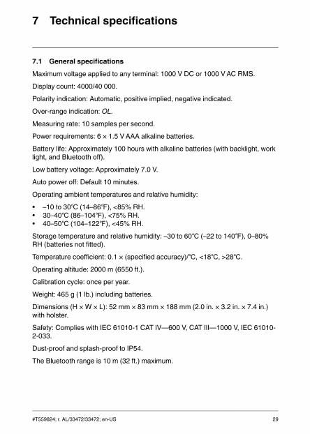
7 Technical specifications
7.1 General specifications
Maximum voltage applied to any terminal: 1000 V DC or 1000 VAC RMS.
Display count: 4000/40 000.
Polarity indication: Automatic, positive implied, negative indicated.
Over-range indication: OL.
Measuring rate: 10 samples per second.
Power requirements: 6 × 1.5 VAAA alkaline batteries.
Battery life: Approximately 100 hours with alkaline batteries (with backlight, worklight, and Bluetooth off).
Low battery voltage: Approximately 7.0 V.
Auto power off: Default 10 minutes.
Operating ambient temperatures and relative humidity:
• –10 to 30 (14–86), <85% RH.• 30–40 (86–104), <75% RH.• 40–50 (104–122), <45% RH.
Storage temperature and relative humidity: –30 to 60 (–22 to 140), 0–80%RH (batteries not fitted).
Temperature coefficient: 0.1 × (specified accuracy)/, <18, >28.
Operating altitude: 2000 m (6550 ft.).
Calibration cycle: once per year.
Weight: 465 g (1 lb.) including batteries.
Dimensions (H × W × L): 52 mm × 83 mm × 188 mm (2.0 in. × 3.2 in. × 7.4 in.)with holster.
Safety: Complies with IEC 61010-1 CAT IV—600 V, CAT III—1000 V, IEC 61010-2-033.
Dust-proof and splash-proof to IP54.
The Bluetooth range is 10 m (32 ft.) maximum.
#T559824; r. AL/33472/33472; en-US 29
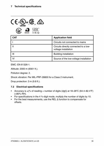
7 Technical specifications
CAT Application field
I Circuits not connected to mains
II Circuits directly connected to a low-voltage installation
III Building installation
IV Source of the low-voltage installation
EMC: EN 61326-1.
Altitude: 2000 m (6561 ft.).
Pollution degree: 2.
Shock vibration: Per MIL-PRF-28800 for a Class 2 instrument.
Drop protection: 3 m (9.8 ft.).
7.2 Electrical specifications
• Accuracy is ±(% of reading + number of digits (dgt)) at 18–28 (64.4–82.4)(<80% RH).
• For specifications in the 4 ¾-digit mode, multiply the number of digits by 10.• For the best measurements, use the REL Δ function to compensate for
offsets.
#T559824; r. AL/33472/33472; en-US 30

7 Technical specifications
Table 7.1 Voltage. Resolution of specifications in the 3 ¾-digit mode.
Mode Range Accuracy
DC
40.00 mV 0.05%+3d
400.0 mV
0.05%+1d
4.000 V
40.00 V
400.0 V
1000 V
40 Hz to70 Hz
70 Hz to1 kHz
1 kHz to5k Hz
5 kHz to20 kHz1
AC
40.00 mV 0.5% + 2d 1.0% + 4d 2.0% + 4d Unspeci-fied
400.0 mV
0.5% + 2d 1.0% + 4d 2.0% + 4d 2.0% +20d4.000 V
40.00 V
400.0V 0.5% + 2d 1.0% + 4d 2.0% +4d2
Unspeci-fied
1000 V 0.5% + 2d 1.0% + 4d Unspeci-fied
Unspeci-fied
1. Below 10% of range, add 10d to accuracy.2. Frequency range 1k to 2k Hz.
Input protection: 1000 V DC or 1000 VAC RMS
Input impedance:
• mV: 1 MΩ, <100 pF.• V: 10 MΩ, <100 pF.
Bandwidth: 40 Hz to 20 kHz.
Minimum resolution: 1 µV in the 40 mV range.
CMRR/NMRR (common/normal mode rejection ratio):
#T559824; r. AL/33472/33472; en-US 31

7 Technical specifications
• VAC: CMRR > 60 dB at DC, 50 Hz/60 Hz.• V DC: CMRR > 100 dB at DC, 50 Hz/60 Hz.• NMRR > 50 dB at DC, 50 Hz/60 Hz.
AC conversion type: AC coupled, true RMS responding, calibrated to the sinewave input. For non-sine waves, add the following crest factor corrections:
• For a crest factor of 1.4–2.0, add 1.0% to the AC accuracy.• For a crest factor of 2.0–2.5, add 2.5% to the AC accuracy.• For a crest factor of 2.5–3.0, add 4.0% to the AC accuracy.
Table 7.2 Current. Resolution of specifications in the 3 ¾-digit mode.
Mode Range Accuracy
DC
40.00 mA
0.2%+1d400.0 mA
4.000 A
10.00 A 0.2%+2d
40 Hz to 70Hz
70 Hz to 1kHz
1 kHz to 10kHz
AC1
40.00 mA1.0%+2d 2.0%+4d 2.0%+4d2
400.0 mA
4.000 A1.0%+2d 2.0%+4d Unspecified
10.00 A1. Below 5% of the AC range, add 20 dgt to the accuracy.2. Below 10% of range, add 10 d to accuracy
Input protection: Equipped with a high-energy fuse.
• mA: 440 mA, 1000 V IR 10 kA fuse (Bussmann DMM-B-44/100)• A: 11 A, 1000 V IR 20 kA fuse (Bussmann DMM-B-11A)
Input impedance:
• mA: 1 Ω at mA input.• A: 10 mΩ at A input.
Bandwidth: 40 Hz to 10 kHz.
#T559824; r. AL/33472/33472; en-US 32

7 Technical specifications
Minimum resolution: 1 µA in the 40 mA range.
Maximum measuring time: 1 minute at A input, 10 minutes at mA input. Rest timeis 20 minutes minimum.
AC conversion type: The AC conversion type is the same as for the voltage.
Table 7.3 AC additional specifications
Mode Range Accuracy
AC+DC
Same as V and A
AC accuracy + 1.0%
VFD AC accuracy for 40–400 Hz
Peak hold AC accuracy + (3.0% +100 dgt) for 40Hz to1kHz
Low-Z Same as V Accuracy + 1.0%
The cut-off frequency of VFD: 800 Hz (–3 dB point).
Attenuation characteristic of VFD: Approx. –24 dB.
Table 7.4 Frequency Counter
Range Resolution Accuracy
400.00 Hz 0.01 Hz
± 5 dgt4.0000 kHz 0.1 Hz
40.000 kHz 1 Hz
100.00 kHz 10 Hz
Minimum sensed frequency: 5 Hz.
#T559824; r. AL/33472/33472; en-US 33
7 Technical specifications
Table 7.5 Frequency counter sensitivity
Function Range Sensitivity(peak to peak)
5 Hz to 10 kHz
Sensitivity(peak to peak)
10–100 kHz
mV40.000 mV 10 mV 10 mV
400.00 mV 100 mV 100 mV
V
4.0000 V 1 V 1 V
40.000 V 10 V 10 V
400.00 V 100 V 100 V
1000 V 600 V Unspecified
mA40.000 mA 10 mA
Unspecified400.00 mA 100 mA
A4.0000 A 1 A
Unspecified10.000 A 6 A
Table 7.6 Resistance. Resolution of specifications in the 3 ¾-digit mode.
Range Resolution Accuracy
400.0 Ω 100 mΩ ±(0.2% + 2 dgt)
4.000 kΩ 1 Ω±(0.2% + 1 dgt)40.00 kΩ 10 Ω
400.0 kΩ 100 Ω
4.000 MΩ 1 kΩ ±(1.0% + 1 dgt)
40.00 MΩ 10 kΩ ±(2.0% + 20 dgt)
Input protection: 1000 V DC or 1000 VAC RMS.
Maximum open circuit voltage: Approx. 2.5 V.
Maximum short test current: Approx. 0.1 mA.
#T559824; r. AL/33472/33472; en-US 34

7 Technical specifications
Table 7.7 Continuity check. Resolution of specifications in the 3 ¾-digit mode.
Range Resolution Accuracy
400.0 Ω 100 mΩ ±(0.2% + 2 dgt)
Input protection: 1000 V DC or 1000 VAC RMS.
Maximum open circuit voltage: Approx. 2.5 V.
Maximum short test current: Approx. 1 mA.
Continuity threshold: Default <30 Ω.
Continuity response time: 10 ms for <10 Ω, 200 ms for >10 Ω.
Continuity indicator: 2 kHz tone buzzer.
Table 7.8 Diode test
Range Resolution Accuracy
2.000 V 1 mV ±(1.5% + 2 dgt)
Input protection: 1000 V DC or 1000 VAC RMS.
Maximum open circuit voltage: Approx. ±2.5 V.
Maximum short test current: Approx. ±1 mA.
Table 7.9 Capacitance
Range Resolution Accuracy
40.00 nF 10 pF ±(1.2% + 20 dgt)
400.0 nF 100 pF
±(0.9% + 2 dgt)4.000 μF 1 nF
40.00 μF 10 nF
400.0 μF 100 nF
4.000 mF 1 μF ±(1.2% + 20 dgt)
40.00 mF 10 μF ±(2.0% + 20 dgt)
#T559824; r. AL/33472/33472; en-US 35

7 Technical specifications
Input protection: 1000 V DC or 1000 VAC RMS.
Table 7.10 Temperature
Range Resolution Accuracy
–328 to 2192 0.1 1.0% + 36d
–200 to 1200 0.1 1.0% + 20d
Input protection: 1000 V DC or 1000 VAC RMS.
NOTE
Accuracy specification assumes the ambient temperature is stable to ±1(±1.8). For ambient temperature changes of ±5 (±9), the rated accuracyapplies after 1 hour.
#T559824; r. AL/33472/33472; en-US 36
8 Technical support for external meters
Website http://www.flir.com/test
Technical support [email protected]
Repairs [email protected]
Phone number +1 855-499-3662 (toll-free)
#T559824; r. AL/33472/33472; en-US 37
9 Warranties
9.1 FLIR Global Limited LifetimeWarrantyA qualifying FLIR Test and Measurement product (the“Product”) purchased either directly from FLIR Commer-cial Systems Inc and affiliates (FLIR) or from an author-ized FLIR distributor or reseller that Purchaser registerson-line with FLIR is eligible for coverage under FLIR’s Lim-ited Lifetime Warranty, subject to the terms and conditionsin this document. This warranty only applies to purchasesof Qualifying Products (see below) purchased and manu-factured after April 1, 2013.
PLEASE READ THIS DOCUMENT CAREFULLY; IT CON-TAINS IMPORTANT INFORMATION ABOUT THE PROD-UCTS THATQUALIFY FOR COVERAGE UNDER THELIMITED LIFETIME WARRANTY, PURCHASER’S OBLI-GATIONS, HOW TO ACTIVATE THE WARRANTY, WAR-RANTYCOVERAGE, AND OTHER IMPORTANT TERMS,CONDITIONS, EXCLUSIONS AND DISCLAIMERS.
1. PRODUCT REGISTRATION. To qualify for FLIR’s Lim-ited Lifetime Warranty, Purchaser must fully register theProduct directly with FLIR on-line at http://www.flir.comwithin Sixty (60) DAYS of the date the Product was pur-chased by the first retail customer (the “Purchase Date”).Qualifying PRODUCTS THATARE NOT REGISTEREDON-LINE WITHIN SIXTY (60) DAYS OF THE PURCHASEDATE WILL HAVE A LIMITED ONE YEARWARRANTYFROM DATE OF PURCHASE.
2. QUALIFYING PRODUCTS. Upon registration, Test andMeasurement products that qualify for coverage underFLIR’s Limited Lifetime Warranty are: MR7x, CM7x,CM8x, DMxx, VP5x not including accessories which mayhave their own warranty.
3. WARRANTY PERIODS. For purposes of the The Lim-ited Lifetime Warranty, Lifetime is defined as seven years(7) after the product is no longer manufactured, or tenyears (10) from date of purchase, whichever is greater.This Warranty is only applicable to the original owner ofthe Products.
Any Product that is repaired or replaced under warranty iscovered under this Limited Lifetime Warranty for one hun-dred eighty days (180) days from the date of return ship-ment by FLIR or for the remaining duration of theapplicable Warranty Period, whichever is longer.
4. LIMITEDWARRANTY. In accordance with the termsand conditions of this Limited Lifetime Warranty, and ex-cept as excluded or disclaimed in this document, FLIRwarrants, from the Purchase Date, that all fully registeredProducts will conform to FLIR’s published Product specifi-cations and be free from defects in materials and work-manship during the applicable Warranty Period.PURCHASER’S SOLE AND EXCLUSIVE REMEDYUNDER THISWARRANTY, AT FLIR’S SOLE DISCRE-TION, IS THE REPAIR OR REPLACEMENT OF
DEFECTIVE PRODUCTS IN A MANNER, AND BYASERVICE CENTER, AUTHORIZED BY FLIR. IF THISREMEDY IS ADJUDICATED TO BE INSUFFICIENT, FLIRSHALL REFUND PURCHASER’S PAID PURCHASEPRICE AND HAVE NO OTHER OBLIGATION OR LIABIL-ITY TO BUYERWHATSOEVER.
5. WARRANTY EXCLUSIONS AND DISCLAIMERS.FLIR MAKES NO OTHERWARRANTYOFANY KINDWITH RESPECT TO THE PRODUCTS. ALL OTHERWARRANTIES, EXPRESS OR IMPLIED, INCLUDINGBUT NOT LIMITED TO IMPLIEDWARRANTIES OF MER-CHANTABILITY, FITNESS FOR A PARTICULAR PUR-POSE (EVEN IF PURCHASER HAS NOTIFIED FLIR OFITS INTENDED USE FOR THE PRODUCTS), AND NON-INFRINGEMENTARE EXPRESSLY EXCLUDED FROMTHIS AGREEMENT.
THISWARRANTY EXPRESSLY EXCLUDES ROUTINEPRODUCT MAINTENANCE, SOFTWARE UPDATES,AND REPLACEMENT OF MANUALS, FUSES, OR DIS-POSABLE BATTERIES. FLIR FURTHER EXPRESSLYDISCLAIMS ANYWARRANTYCOVERAGEWHERETHE ALLEGED NONCONFORMITY IS DUE TO NOR-MALWEAR AND TEAR, OTHER ALTERATION, MODIFI-CATION, REPAIR, ATTEMPTED REPAIR, IMPROPERUSE, IMPROPER MAINTENANCE, NEGLECT, ABUSE,IMPROPER STORAGE, FAILURE TO FOLLOWANYPRODUCT INSTRUCTIONS, DAMAGE (WHETHERCAUSED BYACCIDENT OR OTHERWISE), OR ANYOTHER IMPROPER CARE OR HANDING OF THEPRODUCTS CAUSED BYANYONE OTHER THAN FLIROR FLIR’S EXPRESSLYAUTHORIZED DESIGNEE.
THIS DOCUMENT CONTAINS THE ENTIRE WAR-RANTYAGREEMENT BETWEEN PURCHASER ANDFLIR AND SUPERSEDES ALL PRIORWARRANTY NE-GOTIATIONS, AGREEMENTS, PROMISES ANDUNDERSTANDINGS BETWEEN PURCHASER ANDFLIR. THIS WARRANTY MAY NOT BE ALTEREDWITH-OUT THE EXPRESSWRITTEN CONSENT OF FLIR.
6. WARRANTY RETURN, REPAIR AND REPLACE-MENT. To be eligible for warranty repair or replacement,Purchaser must notify FLIR within thirty (30) days of dis-covering of any apparent defect in materials or workman-ship. Before Purchaser may return a Product for warrantyservice or repair, Purchaser must first obtain a returnedmaterial authorization (RMA) number from FLIR. To obtainthe RMA number Owner must provide an original proof ofpurchase. For additional information, to notify FLIR of anapparent defect in materials or workmanship, or to requestan RMA number, visit http://www.flir.com. Purchaser issolely responsible for complying with all RMA instructionsprovided by FLIR including but not limited to adequatelypackaging the Product for shipment to FLIR and for allpackaging and shipping costs. FLIR will pay for returningto Purchaser any Product that FLIR repairs or replacesunder warranty.
#T559824; r. AL/33472/33472; en-US 38

9 Warranties
FLIR reserves the right to determine, in its sole discretion,whether a returned Product is covered under Warranty. IfFLIR determines that any returned Product is not coveredunder Warranty or is otherwise excluded from Warrantycoverage, FLIR may charge Purchaser a reasonable han-dling fee and return the Product to Purchaser, at Purchas-er’s expense, or offer Purchaser the option of handling theProduct as a non-warranty return.
7. NON-WARRANTY RETURN. Purchaser may requestthat FLIR evaluate and service or repair a Product not cov-ered under warranty, which FLIR may agree to do in itssole discretion. Before Purchaser returns a Product fornon-warranty evaluation and repair, Purchaser must con-tact FLIR by visiting http://www.flir.com to request an eval-uation and obtain an RMA. Purchaser is solelyresponsible for complying with all RMA instructions pro-vided by FLIR including but not limited to adequatelypackaging the Product for shipment to FLIR and for allpackaging and shipping costs. Upon receipt of an author-ized non-warranty return, FLIR will evaluate the Productand contact Purchaser regarding the feasibility of and thecosts and fees associated with Purchaser’s request. Pur-chaser shall be responsible for the reasonable cost ofFLIR’s evaluation, for the cost of any repairs or servicesauthorized by Purchaser, and for the cost of repackagingand returning the Product to Purchaser.
Any non-warranty repair of a Product is warranted for onehundred eighty days (180) days from the date of returnshipment by FLIR to be free from defects in materials andworkmanship only, subject to all of the limitations, exclu-sions and disclaimers in this document.
9.2 FLIR Test and MeasurementLimited 2 Year WarrantyA qualifying FLIR Test and Measurement product (the“Product”) purchased either directly from FLIR Commer-cial Systems Inc and affiliates (FLIR) or from an author-ized FLIR distributor or reseller that Purchaser registerson-line with FLIR is eligible for coverage under FLIR’s Lim-ited Warranty, subject to the terms and conditions in thisdocument. This warranty only applies to purchases ofQualifying Products (see below) purchased and manufac-tured after April 1, 2013.
PLEASE READ THIS DOCUMENT CAREFULLY; IT CON-TAINS IMPORTANT INFORMATION ABOUT THE PROD-UCTS THATQUALIFY FOR COVERAGE UNDER THELIMITEDWARRANTY, PURCHASER’S OBLIGATIONS,HOW TO ACTIVATE THE WARRANTY, WARRANTYCOVERAGE, AND OTHER IMPORTANT TERMS, CON-DITIONS, EXCLUSIONS AND DISCLAIMERS.
1. PRODUCT REGISTRATION. To qualify for FLIR’s Lim-ited Warranty, Purchaser must fully register the Product di-rectly with FLIR on-line at http://www.flir.com within Sixty(60) DAYS of the date the Product was purchased by thefirst retail customer (the “Purchase Date”). QualifyingPRODUCTS THATARE NOT REGISTERED ON-LINE
WITHIN SIXTY (60) DAYS OF THE PURCHASE DATEWILL HAVE A LIMITED ONE YEARWARRANTY FROMDATE OF PURCHASE.
2. QUALIFYING PRODUCTS. Upon registration, Test andMeasurement products that qualify for coverage underFLIR’s Limited Warranty are: VS70 Videoscope, VSAxxArticulation Camera, VSCxx Camera, VSSxx Probe Spool,VST handset, MR02 Pin Extension Probe, and TAxx notincluding accessories which may have their own warranty.
3. WARRANTY PERIODS. The applicable Limited War-ranty Period measured from the Purchase data are:
Products Limited WarrantyPeriod
VS70, VSAxx, VSCxx,VSSxx, VST, MR02,TAxx
TWO (2) Years
Any Product that is repaired or replaced under warranty iscovered under this Limited Warranty for one hundredeighty days (180) days from the date of return shipmentby FLIR or for the remaining duration of the applicableWarranty Period, whichever is longer.
4. LIMITEDWARRANTY. In accordance with the termsand conditions of this Limited Warranty, and except as ex-cluded or disclaimed in this document, FLIR warrants,from the Purchase Date, that all fully registered Productswill conform to FLIR’s published product specificationsand be free from defects in materials and workmanshipduring the applicable Warranty Period. PURCHASER’SSOLE AND EXCLUSIVE REMEDY UNDER THISWAR-RANTY, AT FLIR’S SOLE DISCRETION, IS THE REPAIROR REPLACEMENT OF DEFECTIVE PRODUCTS IN AMANNER, AND BYA SERVICE CENTER, AUTHORIZEDBY FLIR. IF THIS REMEDY IS ADJUDICATED TO BE IN-SUFFICIENT, FLIR SHALL REFUND PURCHASER’SPAID PURCHASE PRICE AND HAVE NO OTHER OBLI-GATION OR LIABILITY TO BUYERWHATSOEVER.
5. WARRANTY EXCLUSIONS AND DISCLAIMERS.FLIR MAKES NO OTHERWARRANTYOFANY KINDWITH RESPECT TO THE PRODUCTS. ALL OTHERWARRANTIES, EXPRESS OR IMPLIED, INCLUDINGBUT NOT LIMITED TO IMPLIEDWARRANTIES OF MER-CHANTABILITY, FITNESS FOR A PARTICULAR PUR-POSE (EVEN IF PURCHASER HAS NOTIFIED FLIR OFITS INTENDED USE FOR THE PRODUCTS), AND NON-INFRINGEMENTARE EXPRESSLY EXCLUDED FROMTHIS AGREEMENT.
THISWARRANTY EXPRESSLY EXCLUDES ROUTINEPRODUCT MAINTENANCE, SOFTWARE UPDATES,AND REPLACEMENT OF FUSES, OR DISPOSABLEBATTERIES. FLIR FURTHER EXPRESSLY DISCLAIMSANY WARRANTYCOVERAGE WHERE THE ALLEGEDNONCONFORMITY IS DUE TO NORMALWEAR ANDTEAR, OTHER ALTERATION, MODIFICATION, REPAIR,ATTEMPTED REPAIR, IMPROPER USE, IMPROPER
#T559824; r. AL/33472/33472; en-US 39

9 Warranties
MAINTENANCE, NEGLECT, ABUSE, IMPROPER STOR-AGE, FAILURE TO FOLLOWANY PRODUCT INSTRUC-TIONS, DAMAGE (WHETHER CAUSED BYACCIDENTOR OTHERWISE), OR ANYOTHER IMPROPER CAREOR HANDING OF THE PRODUCTS CAUSED BYANY-ONE OTHER THAN FLIR OR FLIR’S EXPRESSLYAU-THORIZED DESIGNEE.
THIS DOCUMENT CONTAINS THE ENTIRE WAR-RANTYAGREEMENT BETWEEN PURCHASER ANDFLIR AND SUPERSEDES ALL PRIORWARRANTY NE-GOTIATIONS, AGREEMENTS, PROMISES ANDUNDERSTANDINGS BETWEEN PURCHASER ANDFLIR. THISWARRANTY MAY NOT BE ALTEREDWITH-OUT THE EXPRESSWRITTEN CONSENT OF FLIR.
6. WARRANTY RETURN, REPAIR AND REPLACE-MENT. To be eligible for warranty repair or replacement,Purchaser must notify FLIR within thirty (30) days of dis-covering of any apparent defect in materials or workman-ship. Before Purchaser may return a Product for warrantyservice or repair, Purchaser must first obtain a returnedmaterial authorization (RMA) number from FLIR. To obtainthe RMA number Owner must provide an original proof ofpurchase. For additional information, to notify FLIR of anapparent defect in materials or workmanship, or to requestan RMA number, visit http://www.flir.com. Purchaser issolely responsible for complying with all RMA instructionsprovided by FLIR including but not limited to adequatelypackaging the Product for shipment to FLIR and for allpackaging and shipping costs. FLIR will pay for returningto Purchaser any Product that FLIR repairs or replacesunder warranty.
FLIR reserves the right to determine, in its sole discretion,whether a returned Product is covered under Warranty. IfFLIR determines that any returned Product is not coveredunder Warranty or is otherwise excluded from Warrantycoverage, FLIR may charge Purchaser a reasonable han-dling fee and return the Product to Purchaser, at Purchas-er’s expense, or offer Purchaser the option of handling theProduct as a non-warranty return.
7. NON-WARRANTY RETURN. Purchaser may requestthat FLIR evaluate and service or repair a Product not cov-ered under warranty, which FLIR may agree to do in itssole discretion. Before Purchaser returns a Product fornon-warranty evaluation and repair, Purchaser must con-tact FLIR by visiting http://www.flir.com to request an eval-uation and obtain an RMA. Purchaser is solelyresponsible for complying with all RMA instructions pro-vided by FLIR including but not limited to adequatelypackaging the Product for shipment to FLIR and for allpackaging and shipping costs. Upon receipt of an author-ized non-warranty return, FLIR will evaluate the Productand contact Purchaser regarding the feasibility of and thecosts and fees associated with Purchaser’s request. Pur-chaser shall be responsible for the reasonable cost ofFLIR’s evaluation, for the cost of any repairs or servicesauthorized by Purchaser, and for the cost of repackagingand returning the Product to Purchaser.
Any non-warranty repair of a Product is warranted for onehundred eighty days (180) days from the date of returnshipment by FLIR to be free from defects in materials andworkmanship only, subject to all of the limitations, exclu-sions and disclaimers in this document.
#T559824; r. AL/33472/33472; en-US 40

A note on the technical production of this publicationThis publication was produced using XML — the eXtensible Markup Language.For more information about XML, please visit http://www.w3.org/XML/A note on the typeface used in this publicationThis publication was typeset using Linotype Helvetica™World. Helvetica™ wasdesigned by Max Miedinger (1910–1980)LOEF (List Of Effective Files)T501024.xml; en-US; AL; 33472; 2016-02-18
#T559824; r. AL/33472/33472; en-US 42


last page
Publ. No.: T559824Release: ALCommit: 33472Head: 33472Language: en-USModified: 2016-02-18Formatted: 2016-02-18
Websitehttp://www.flir.comCustomer supporthttp://support.flir.comCopyright© 2016, FLIR Systems, Inc. All rights reserved worldwide.DisclaimerSpecifications subject to change without further notice. Models and accessoriessubject to regional market considerations. License procedures may apply.Products described herein may be subject to US Export Regulations. Pleaserefer to [email protected] with any questions.