users manual - mitsubishi imagingmitsubishiimaging.com/support/manuals/1630iiir_usermanual.pdf ·...
TRANSCRIPT


Before attempting to operate this product, you shouldthoroughly read and fully understand all the contents of thismanual.Administrators and supervisors shall not instruct anyone tooperate or inspect this machine unless he/she is familiarwith all the contents of this document.
USERS MANUALIII

i
Warning
For Your Safety
- This manual must be thoroughly read and understood by all operators before they attempt
to use SDP-Eco 1630 III.
- This manual provides general guidelines, precautions and warnings for the safe operation
of this machine. Very serious accidents may occur if this machine is utilized without
following this manual and we shall bear absolutely no liability or responsibility for the
consequences.
- The warning labels for hazard prevention area attached to dangerous parts or areas of
the machine. Study and understand all the specific dangers involved and how they can
be avoided.
- Keep this manual available and near the machine at all times so that it can be
immediately referred to whenever necessary.
- Look up the name, address and phone number of our nearest dealer or branch office
(listed on the back page of this manual), and post the information prominently for quick
reference.
- Please make sure that this manual reaches everyone charged with operating this
machine.
Machine operators must thoroughly read Chapter 1. Do not turn on the machine's powersupply until all of the precautions have been read and understood. Very seriousaccidents may occur if this instruction is not observed.Administrators and supervisors shall not instruct anyone to operate or inspect the SDP-Eco 1630 III unless he/she is familiar with all the contents of this document.

Compliance with CISPR Rules
This is a Class A product. In a domestic environment this product may cause radio
interference in which case the user may be required to take adequate measures.
Compliance with FCC Rules
Notice for the USA
This machine has been tested and found to comply with the limits for a Class A digital
device, pursuant to part 15 of the FCC Rules. These limits are designed to provide
reasonable protection against harmful interference when the machine is operated in a
commercial environment. This machine generates, uses, and can radiate radio frequency
energy and, if not installed and used in accordance with the instruction manual, may cause
harmful interference to radio communications. Operation of this machine in a residential
area is likely to cause harmful interference in which case the user will be required to correct
the interference at their own expense.
Changes or modifications not expressly approved by Mitsubishi Paper Mills Limited could
void the user's authority to operate the machine.
Notice for Canada
This Class A digital apparatus meets all requirements of the Canadian Interference-Causing
Unit Regulations.
Cet appareil numérique de la Class A respecte toutes les exigences du Règlement sur le
matériel brouilleur du Canada.
When export the machine
International transfer of this product, any of its parts, components and/or software must be
carried out in compliance with the relevant laws and ordinance of the country of export and
the country of product end-use. We do not assume any responsibility of liability for product
transferred without regard to proper export/import regulations or procedures.
Limit of responsibility
Please note that machine specifications are subject to change without notice for updates and
improvements. This may cause inconsistencies between the contents of this manual and
the machine you currently possess.
We shall not be held responsible for any damage caused by conditions beyond our control
such as customer modification, disassembly or misuse of our machine, programs or
software, or their use in a defective or deficient environment.
We assume no responsibility or liability for any damage or consequential and/or indirect
losses resulting from any accident or malfunction that might occur during the operation of
this machine.
Copyright
©2005: Mitsubishi Paper Mills Limited.
The copyright for this entire manual belongs to Mitsubishi Paper Mills Limited.
Copying, reprinting, or reproduction of this manual in whole or in part in any medium without
our express consent infringes upon the copyright and the rights of the publisher.
ii

iii
Introductory Note
Thank you very much for choosing our product. We sincerely hope that you will enjoy using
the SDP-Eco 1630 III, and fully utilize all its functions and capabilities.
This users manual describes how to safely operate this machine and explains all the basic
procedures for data setting, maintenance, inspections, etc.
As noted below, however, it is the client's obligation to obtain or prepare all the necessary
material safety data sheets ("MSDS") for any chemical substances used during the client's
operation on this machine. Although great care has been taken in preparing this manual, if
you find that certain points seem unclear or in error, please contact Mitsubishi Paper Mills
Limited.
This manual contains the following sections:
Chapter 1 "On Safety"
This chapter describes instructions to be observed for the safest possible operation of the product.
Please make sure to read this chapter before turning on the power to the product.
Chapter 2 to 6
These chapters provide relevant knowledge and reference information for machine operation.
Please read them carefully before attempting to operate the machine.
Chapter 7 to 9
These chapters describe daily maintenance procedures and troubleshooting methods as well as
supplying various technical information. Please read through them as necessary.

iv
About this manualIn this manual, important supplementary remarks are classified as either WARNINGs,
CAUTIONs, Cautions, or Notes.
Since remarks under WARNING and CAUTION headlines call attention to conditions and
operations that may result in accidents or physical injuries, be sure to thoroughly read and
observer their instructions.
Indicates a potentially hazardous situation which, if not
avoided or properly handled, could possibly result in
death or serious injury.
Indicates a potentially hazardous situation which, if not
avoided or properly handled, could possibly result in
minor or moderate injury.
Note
Caution
Caution
Warning
Indicates a situation that could either cause damage to the machine,
destroy data necessitate extensive reduplicated effort. Strictly follow the
noted instructions.
Provides supplementary information or information to prevent incorrect
operations.

v
Contents
Chapter 1 On Safety
1.1 When using the machine ••••••••••••••••••••••••••••••••••••••••••••••••••••••••••••••••••••1
1.2 Warning labels and attachment positions ••••••••••••••••••••••••••••••••••••••••••••4
1.3 Handling processing chemicals ••••••••••••••••••••••••••••••••••••••••••••••••••••••••••6
1.4 Before connecting the power cable•••••••••••••••••••••••••••••••••••••••••••••••••••••8
1.5 Operation precautions ••••••••••••••••••••••••••••••••••••••••••••••••••••••••••••••••••••••••9
1.6 Precautions during transport and installation •••••••••••••••••••••••••••••••••••••10
1.7 SDP-Eco 1630 III Installation ••••••••••••••••••••••••••••••••••••••••••••••••••••••••••••10
1.8 Maintenance ••••••••••••••••••••••••••••••••••••••••••••••••••••••••••••••••••••••••••••••••••••12
1.9 Machine disposal••••••••••••••••••••••••••••••••••••••••••••••••••••••••••••••••••••••••••••••13
Chapter 2 Names of Machine Components and Parts
2.1 Main unit ••••••••••••••••••••••••••••••••••••••••••••••••••••••••••••••••••••••••••••••••••••••••••15
2.2 Operation panel••••••••••••••••••••••••••••••••••••••••••••••••••••••••••••••••••••••••••••••••17
2.3 Safety switch••••••••••••••••••••••••••••••••••••••••••••••••••••••••••••••••••••••••••••••••••••18
Chapter 3 Handling plates
3.1 Plate setting •••••••••••••••••••••••••••••••••••••••••••••••••••••••••••••••••••••••••••••••••••••19
3.2 Plate end processing ••••••••••••••••••••••••••••••••••••••••••••••••••••••••••••••••••••••••23
Chapter 4 Operation
4.1 Cable connection check••••••••••••••••••••••••••••••••••••••••••••••••••••••••••••••••••••25
4.2 Turning ON the power switch ••••••••••••••••••••••••••••••••••••••••••••••••••••••••••••26
4.3 Initialization ••••••••••••••••••••••••••••••••••••••••••••••••••••••••••••••••••••••••••••••••••••••26
4.4 Data input for the set plate (This procedure is necessary when
loading the plate.) •••••••••••••••••••••••••••••••••••••••••••••••••••••••••••••••••••••••••••••27
4.5 Execution of Pre. Feed command (This procedure is necessary
when loading the plate.)••••••••••••••••••••••••••••••••••••••••••••••••••••••••••••••••••••28
4.6 Exposure••••••••••••••••••••••••••••••••••••••••••••••••••••••••••••••••••••••••••••••••••••••••••29
4.7 Processor section•••••••••••••••••••••••••••••••••••••••••••••••••••••••••••••••••••••••••••••31
4.8 Collecting exposed plates •••••••••••••••••••••••••••••••••••••••••••••••••••••••••••••••••34
4.9 Turning OFF the power supply and inspection at shutdown •••••••••••••••34

vi
Chapter 5 Menus and panel displays
5.1 User menu •••••••••••••••••••••••••••••••••••••••••••••••••••••••••••••••••••••••••••••••••••••••37
5.2 Panel operation ••••••••••••••••••••••••••••••••••••••••••••••••••••••••••••••••••••••••••••••••39
Chapter 6 User menu
6.1 Plate data•••••••••••••••••••••••••••••••••••••••••••••••••••••••••••••••••••••••••••••••••••••••••41
6.2 Laser menu ••••••••••••••••••••••••••••••••••••••••••••••••••••••••••••••••••••••••••••••••••••••42
6.3 Pre. Feed menu •••••••••••••••••••••••••••••••••••••••••••••••••••••••••••••••••••••••••••••••44
6.4 Image Data menu•••••••••••••••••••••••••••••••••••••••••••••••••••••••••••••••••••••••••••••44
6.5 Mode menu ••••••••••••••••••••••••••••••••••••••••••••••••••••••••••••••••••••••••••••••••••••••44
6.6 Maintenance menu•••••••••••••••••••••••••••••••••••••••••••••••••••••••••••••••••••••••••••45
6.7 Rinse •••••••••••••••••••••••••••••••••••••••••••••••••••••••••••••••••••••••••••••••••••••••••••••••45
Chapter 7 Maintenance
7.1 Cutter blade replacement••••••••••••••••••••••••••••••••••••••••••••••••••••••••••••••••••47
7.2 Cylindrical lens cleaning •••••••••••••••••••••••••••••••••••••••••••••••••••••••••••••••••••48
7.3 Filter cleaning•••••••••••••••••••••••••••••••••••••••••••••••••••••••••••••••••••••••••••••••••••49
7.4 Punch dust removal••••••••••••••••••••••••••••••••••••••••••••••••••••••••••••••••••••••••••50
7.5 Cleaning the processor section •••••••••••••••••••••••••••••••••••••••••••••••••••••••••51
7.6 Cleaning the washing tank••••••••••••••••••••••••••••••••••••••••••••••••••••••••••••••••59
7.7 Replacing the diffusion sheet (SLM-EAC, SLM-EST)•••••••••••••••••••••••••63
7.8 List of expendable parts••••••••••••••••••••••••••••••••••••••••••••••••••••••••••••••••••••65
7.9 How to order parts ••••••••••••••••••••••••••••••••••••••••••••••••••••••••••••••••••••••••••••65
Chapter 8 Message
8.1 Message ••••••••••••••••••••••••••••••••••••••••••••••••••••••••••••••••••••••••••••••••••••••••••67
8.2 Displaying and clearing errors•••••••••••••••••••••••••••••••••••••••••••••••••••••••••••67
8.3 Status display•••••••••••••••••••••••••••••••••••••••••••••••••••••••••••••••••••••••••••••••••••68
8.4 Warning display••••••••••••••••••••••••••••••••••••••••••••••••••••••••••••••••••••••••••••••••68
8.5 List of error messages ••••••••••••••••••••••••••••••••••••••••••••••••••••••••••••••••••••••69
8.6 Jam removal procedure ••••••••••••••••••••••••••••••••••••••••••••••••••••••••••••••••••••71
Chapter 9 Specifications
9.1 Basic specifications ••••••••••••••••••••••••••••••••••••••••••••••••••••••••••••••••••••••••••73
9.2 Overview diagram ••••••••••••••••••••••••••••••••••••••••••••••••••••••••••••••••••••••••••••74

Chapter1 On Safety
- 1 -
Chapter 1 On Safety
SDP-Eco 1630 III was designed and manufactured with special attention tosafety considerations. However, it is impossible either to eliminate allpotential sources of danger from such products or to anticipate all possiblehazards and misuses. It is therefore critical that you both familiarizeyourself, all your operators and other relevant personnel with all of the notedprecautions, countermeasures and related procedures, and take maximumcare when operating this machine.
1.1 When using the machine• Grounding connection
- In order to preventelectric shock at the ACpower supply unit, besure to connect theground in accordancewith operation siteregulations (resistance:less than 100 ohms)using the SDP-Eco 1630III exclusive wire.
- Even when the user'spresent facility outlet canbe with the SDP-Eco 1630 III power plug with ground, make sure thatthe ground pole on the outlet is connected with ground in accordancewith operation site regulations (resistance: less than 100 ohms)
Following all relevant local wiring regulations, prepare a grounded(less than 100 ohms) power supply outlet that can accept thismachine's power plug.
• Power supply- Prepare a power supply that satisfies all the requirements stipulated in
the specification sheet.- Always provide circuit breakers for unit or devices that use water or
chemicals.- Please entrust all wiring, connections and other electrical work to an
authorized electrician.
• Maintenance and safe passage during emergenciesA minimum of 60 cm clearance is required around the machine at alltimes to afford adequate space for maintenance and safe passage duringemergencies. Never allow this space to become blocked with anyobjects, wires, or other obstacles.
Warning

SDP-Eco1630 III USERS MANUAL
- 2 -
Chapter 1 On Safety
• This machine incorporates a power supply unit.
Do not use a bubble type extinguisher when a fire occurs. It may cause
electric shocks. Place a powder type extinguisher near the machine.
• The SDP-Eco 1630 III is equipped with a leakage circuit breaker.
If a short circuit occurs in the machine, the breaker is automatically
activated and shuts off the circuit.
Occasionally the main unit will not activate when you turn ON thePower Switch because the leakage breaker inside the main unithas turned itself OFF.In such a case, contact your local dealer where you purchased themachine and ask a service person to check out the condition.
• This machine incorporates high current electrical circuits.
Touching the electrical circuits of this machine with any part of your
body can cause serious injury or death. Please contact the dealer where
you purchased this machine when maintenance or inspections are
required.
• Safety switches
To ensure operator safety, this machine is provided with safety switches.
If a front door is opened while the machine is running, a safety switch is
activated and operation is immediately stopped.
(Refer to "Chapter 2 Names of Machine Component and Parts".)
Warning
Chapter 1 On Safety
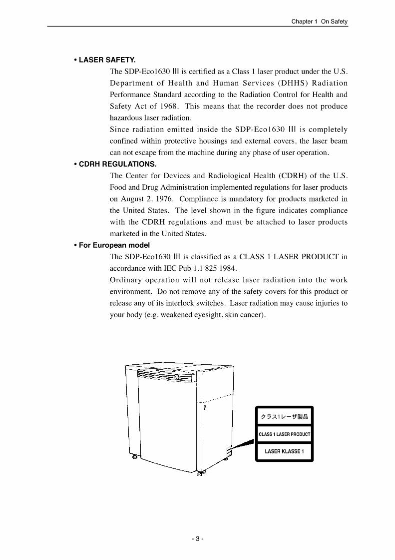
• LASER SAFETY.
The SDP-Eco1630 III is certified as a Class 1 laser product under the U.S.
Department of Health and Human Services (DHHS) Radiation
Performance Standard according to the Radiation Control for Health and
Safety Act of 1968. This means that the recorder does not produce
hazardous laser radiation.
Since radiation emitted inside the SDP-Eco1630 III is completely
confined within protective housings and external covers, the laser beam
can not escape from the machine during any phase of user operation.
• CDRH REGULATIONS.
The Center for Devices and Radiological Health (CDRH) of the U.S.
Food and Drug Administration implemented regulations for laser products
on August 2, 1976. Compliance is mandatory for products marketed in
the United States. The level shown in the figure indicates compliance
with the CDRH regulations and must be attached to laser products
marketed in the United States.
• For European model
The SDP-Eco1630 III is classified as a CLASS 1 LASER PRODUCT in
accordance with IEC Pub 1.1 825 1984.
Ordinary operation will not release laser radiation into the work
environment. Do not remove any of the safety covers for this product or
release any of its interlock switches. Laser radiation may cause injuries to
your body (e.g. weakened eyesight, skin cancer).
- 3 -

1.2 Warning labels and attachment positionsWarning labels are attached to dangerous parts or areas of the machine. All
operators and maintenance personnel must follow the instructions written on
these labels.- Do not remove or deface any of these warning labels.- Labels must always be clearly visible without any obstacles shielding or
obscuring them.- If a label is removed or defaced, replace it with a new warning label as
soon as possible. Please contact the dealer where you purchased thismachine for new labels.
• Types of warning labels
Hazard Safe handling method
Contains processing chemicals. Direct contact with these chemicals due to splashing or overflow may result in skin. irritation, blindness, or burns.
Always wear protective gear such as safety glasses, rubber gloves, masks, and rubber aprons.Read all instructions and warnings for processing chemicals.
Hazard
Hands or fingers may get caught.
Keep hands, fingers and the rest of the body away during operation. Always turn OFF the main power supply and the power switch on the machine before approaching.
Sections marked with this label contain functions or components which could cause personal injury.
Keep hands, fingers and the rest of the body away from the machine while it is running. If you must physically touch the machine, always turn the power supply OFF beforehand.
Safe handling method
Safe handling methodHazard
SDP-Eco1630 III USERS MANUAL
- 4 -
Chapter 1 On Safety
(1) Causticagent
(2) HazardousMovingSection
(3) Caution

Chapter 1 On Safety
- 5 -
Chapter 1 On Safety
• The locations of the machine's warning labels are shown below.
(1)
There are sections where the voltages are dangerously high. Direct contact with these sections (marked with this label) can cause severe shock and potentially fatal injuries.
The parts or sections marked with this label should be avoided. Be careful not to touch them with your bare bands or any part of your body.
Safe handling methodHazard
(4) Electricshock
(2) (3)
(4)
Cutter blade replacementprocedure

SDP-Eco1630 III USERS MANUAL
- 6 -
Chapter 1 On Safety
1.3 Handling processing chemicals
The SDP-Eco 1630 III uses processing chemicals to activate andstabilize exposed plates. The processing chemicals used in thismachine are not generally dangerous to humans, but failure to usethem in the correct manner is dangerous. Be sure to handle allprocessing chemicals with care.
Cautions for use of processing chemicals
Inflammation may occur if processing chemicals come in contactwith the eyes or skin, so be sure to wear protective gear (safetygoggles and rubber gloves) when handling the chemicals.Keep out of reach of children.
What to do in case of emergency
If chemicals come in contact with the eyes, immediately rinse withclean running water for at least 15 minutes. If the inflammationpersists, consult an eye specialist.If chemicals come in contact with the skin, immediately rinse underclean running water.If chemicals are swallowed, immediately consult a physician.Report the ingredients of the chemical or solution to the physician.
Cautions for handling waste chemicals
These chemicals have high COD and pH levels (especially theactivator) and cannot be disposed of by simply pouring them downthe drain. Please have processing chemicals removed by acertified waste management specialist.
Caution
Warning
Caution
Caution
Chapter 1 On Safety
- 7 -
Chapter 1 On Safety
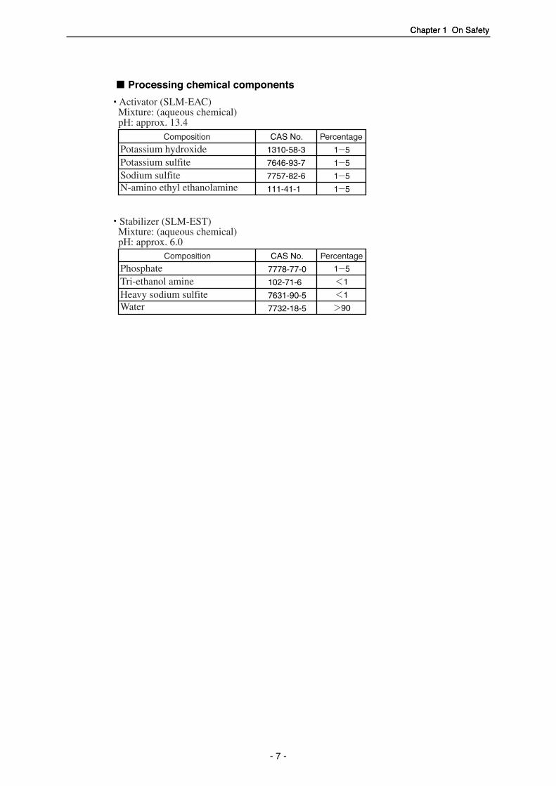
Processing chemical components
Activator (SLM-EAC)Mixture: (aqueous chemical)pH: approx. 13.4
Stabilizer (SLM-EST)Mixture: (aqueous chemical)pH: approx. 6.0
Composition CAS No. Percentage
1310-58-3
7646-93-7
7757-82-6
111-41-1
Potassium hydroxidePotassium sulfiteSodium sulfiteN-amino ethyl ethanolamine
7778-77-0
102-71-6
7631-90-5
7732-18-5
PhosphateTri-ethanol amineHeavy sodium sulfiteWater
Composition CAS No. Percentage

SDP-Eco1630 III USERS MANUAL
- 8 -
Chapter 1 On Safety
1.4 Before connecting the power cable• Power supply
- Check that the powerswitch on the SDP-Eco1630 III is turned OFFbefore connecting thepower plug to the user'spower outlet. (Refer to"Chapter 2: Names ofMachine Component andParts".)
• Power cables- Always use grounded
power cables whenconnecting to thismachine.
- If you find anything thatmight indicate powercable damage such asunusual deformations orsurface flaws, immediate-ly turn OFF the powersupply, pull the powerplug from its outlet andcontact the dealer where you purchased this machine.
- Do not place heavy objects or articles with sharp blades anywhere on thepower cable or forcefully pull at it.
- Never connect the power cable to a shared or overloaded outlet ordistribution socket.
- Please contact our nearest dealer before attempting to extend the powercable.
If you notice any problems with the power cable such as scratchesor deformities, immediately turn OFF the main power supply switchand contact the dealer where you purchased this machine.
Power plug with earth wire
Warning

Chapter 1 On Safety
- 9 -
Chapter 1 On Safety
1.5 Operation precautions
• Do not turn the machine's power supply ON or start operation until this
manual has been thoroughly read and fully understood.
• All operators must wear appropriate work clothing and should never wear
necklaces, scarves, or other accessories which could be caught by moving
parts and cause accidents.
• Do not operate the machine if you feel in anyway sick, nauseous or
unsteady.
• If you notice that the machine is in any way abnormal, immediately report
the situation to your supervisor for appropriate action.
• The SDP-Eco 1630 III can perform continuous automatic operation, but it
must not be operated continuously without an operator in attendance.
An operator trained to take appropriate initial corrective actions should
always be in attendance to deal immediately with any emergencies that
may arise.
• When your SDP-Eco 1630 III will not be operated for an extended period
of time, be sure to unplug the power cord. Check for any dust or
contamination in the outlet, power plug, and/or the AC power socket on
your SDP-Eco 1630 III at least once a year.
• During operation, do not open any of the unit's doors or covers. Opening
these doors or covers may be hazardous to the safety of operators and
other persons working in the vicinity, and may also damage the machine.
• Power failure
If a power failure occurs due to an external reason, immediately turn OFF
the power switch and the SDP-Eco 1630 III.
When power is recovered, supply power again, referring to "4.2 Turning
ON the power switch".
Cap
Buttoned
Safety shoes(preferable)
Gloves (or wet hands)
Open cuffs
Loose or dangling necktie
Items hanging from clothes
Over-long trousers
Slippers or sandals
Always avoid clothing, gear, oraccessories that could in any waybe caught up in the machine.
Appropriate Unacceptable

SDP-Eco1630 III USERS MANUAL
- 10 -
Chapter 1 On Safety
1.6 Precautions during transport and installation
• The weight of the SDP-Eco 1630 III is described in "Chapter 9:
Specifications"Make sure the floor is fully capable of handling 2500 N/m2
(approx. 55 lbs/ft2) or heavier loading before installing the SDP-Eco 1630 III .
• Transport and installation
This machine's transport and installation must always be handled by
engineers and contractors assigned by Mitsubishi Paper Mills Limited.
We shall bear no responsibility whatever for any unit breakage, damage,
or malfunctions caused by or during transport or installation performed by
anyone other than the above specified personnel. Whenever your
machine must moved, transferred, or reinstalled, please entrust all
procedures to our nearest branch office or dealer.
1.7 SDP-Eco 1630 III Installation• Installation environment
Installing the machine in the following locations may cause machine damage
or malfunctions. Do not install the machine anywhere that is exposed or
subject to:
* Locations with strong and/or
persistent vibration
* Locations with an uneven
floor
Chapter 1 On Safety
- 11 -
Chapter 1 On Safety
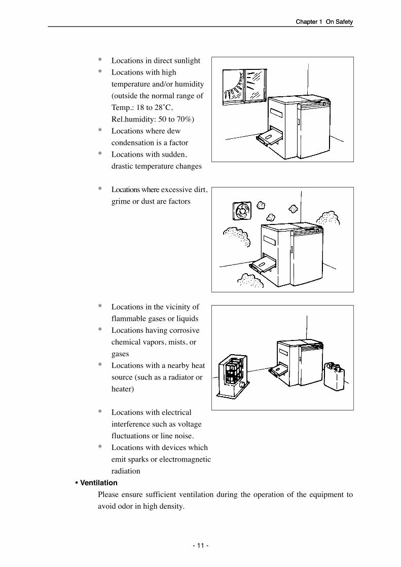
* Locations in direct sunlight
* Locations with high
temperature and/or humidity
(outside the normal range of
Temp.: 18 to 28˚C,
Rel.humidity: 50 to 70%)
* Locations where dew
condensation is a factor
* Locations with sudden,
drastic temperature changes
* Locations where excessive dirt,
grime or dust are factors
* Locations in the vicinity of
flammable gases or liquids
* Locations having corrosive
chemical vapors, mists, or
gases
* Locations with a nearby heat
source (such as a radiator or
heater)
* Locations with electrical
interference such as voltage
fluctuations or line noise.
* Locations with devices which
emit sparks or electromagnetic
radiation
• Ventilation
Please ensure sufficient ventilation during the operation of the equipment to
avoid odor in high density.

SDP-Eco1630 III USERS MANUAL
- 12 -
Chapter 1 On Safety
• Installation space
As shown in figure below, clearance is required around the machine at all
times to assure adequate space for maintenance and safe passage during
emergencies.
1.8 Maintenance• Maintenance that requires tools may only be performed by persons who
have been specially
trained with our authorized
curriculum.
• During machine mainte-
nance, the operator must
make it clear that the
machine should not be
turned ON and prevent
any person other than our
authorized technician(s)
from touching the
machine.
• Be sure to turn OFF the power switch and remove the power plug from
the outlet before you start maintenance, cleaning or repairs.
Power switch
(Unit: cm)
40 o
r lo
nger
79.5
40 orlonger 70 or longer146.5
66.9
100
100
or
long
er

Chapter 1 On Safety
- 13 -
Chapter 1 On Safety
1.9 Machine disposal
• To protect the environment, always commission a special authorized
contractor to dispose of your old machine(s).
• Commission an ordinary contractor to dispose of parts discarded or
replaced during the repair processing.

SDP-Eco1630 III USERS MANUAL
- 14 -

Chapter 2 Names of Machine Components and Parts
Chapter 2 Names of Machine Components and Parts
The SDP-Eco 1630 III consists of the following parts.
2.1 Main unit
- 15 -
Power switch
Plate setting cover
Wide SCSI connector
Operation panel
Front door
Nip roller clearance handle
Filter
Plate receiving tray
AC power socket
Arm

SDP-Eco1630 III USERS MANUAL
- 16 -
Safety switch
Rinse waterreplenisher bottle
EST replenisherbottle (stabilizer)
EAC replenisherbottle (activator)
Waste chemical tank
Plate take up unit Cutter unitCylindrical lens
Chapter 2 Names of Machine Components and Parts
- 17 -
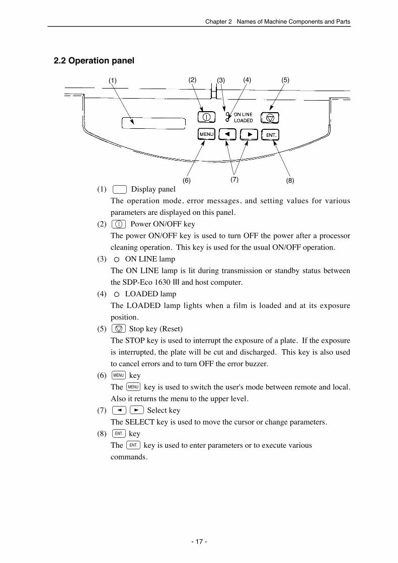
2.2 Operation panel
(1) Display panel
The operation mode, error messages, and setting values for various
parameters are displayed on this panel.
(2) Power ON/OFF key
The power ON/OFF key is used to turn OFF the power after a processor
cleaning operation. This key is used for the usual ON/OFF operation.
(3) ON LINE lamp
The ON LINE lamp is lit during transmission or standby status between
the SDP-Eco 1630 III and host computer.
(4) LOADED lamp
The LOADED lamp lights when a film is loaded and at its exposure
position.
(5) Stop key (Reset)
The STOP key is used to interrupt the exposure of a plate. If the exposure
is interrupted, the plate will be cut and discharged. This key is also used
to cancel errors and to turn OFF the error buzzer.
(6) key
The key is used to switch the user's mode between remote and local.
Also it returns the menu to the upper level.
(7) Select key
The SELECT key is used to move the cursor or change parameters.
(8) key
The key is used to enter parameters or to execute various
commands.
����
����
MENU
MENU
(2)(1) (3) (4) (5)
(6) (7) (8)
SDP-Eco1630 III USERS MANUAL
2.3 Safety switch
This machine is equipped with a safety interlock switch which detects the
front door's open/closed status.(See page 16) If this switch detects that the
front door is open, this machine cannot perform any operations.
If the front door is opened during data transmission from the hostcomputer, image exposure or plate transfer, all machine operationsstop. This will cause problems with data transfer and in the image data.
Use of controls or adjustment or performance of procedures otherthan those specified herein may result in hazardous radiationexposure. Operations or adjustments other than those specifiedherein may result in damage to your body(e.g.weakened eyesight,skin cancer).
Caution
- 18 -
Warning

Chapter 3 Handling Plates
Chapter 3 Handling plates
3.1 Plate setting1) Open the plate setting cover and,
holding the lever with your thumb,
take the spool shaft out.
2) Refer to your plate width, and
align the edge of the spool plate
boss to the groove in the spool
shaft. The spool shaft grooves are
numbered from outer side in the
following order: 414, 404, 400,
370, 340, 335, 324, 310, 305, 279,
254, and 229.
Red tape is affixed to thereference side of thespool shaft.
3) To prevent the reference side of
the spool plate from shifting from
its designated position, insert a
screw driver into the set screw
hole and firmly fix the set screw to
the spool shaft.
Always fix the set screw on the
flat side of the spool shaft.
Caution
- 19 -
Lever
Plate setting cover
229 (9)254 (10)279 (11)
305 (12)310 (12 1/5)
MarkerSpool plate
Set screw
Red tape
Spool shaft
Edge of boss
400 (15 3/4)
324 (12 3/4)335 (13 3/16)340 (13 3/8)370 (14 9/16)
404 (15 7/8)414 (16 3/10)

SDP-Eco1630 III USERS MANUAL
4) Lower a roll of plate (wound in
the same direction as in the figure
on the left) down over the spool
shaft. (The shaft should be
standing vertically with the
reference side of the spool plate as
its base.).
Firmly press the edge of the plate
roll against the spool plate
(reference side) until they touch
equally all around the periphery of
the roll.
5) Firmly snap the contact side of the
spool plate down over the spool
shaft and continue pressing the
plate (contact side) downward to
the edge of the plate roll until
there are no intervening gaps.
Position the contact side of the
spool plate so that its set screw is
positioned 180o opposite the one
on the reference side.
The two set screws arefixed 180o opposite eachother to prevent rotationalimbalance due to theweight of the screws.
Note
- 20 -
Plate
Make sure that the lateral edgesof the plate are still even afterthe roll is set on the spool shaft.
Spool plate(contact side)
Plate
No gaps here.
Spool plate (reference side)
Set screw(contact side)
Must be locatedexactly (180o )opposite the oneon the referenceside.
Set screw(referenceside)
Chapter 3 Handling Plates
Confirm that there is no gap
between the plate roll and the
spool plate and that the set screw
is placed in the correct position
and then tighten the set screw.
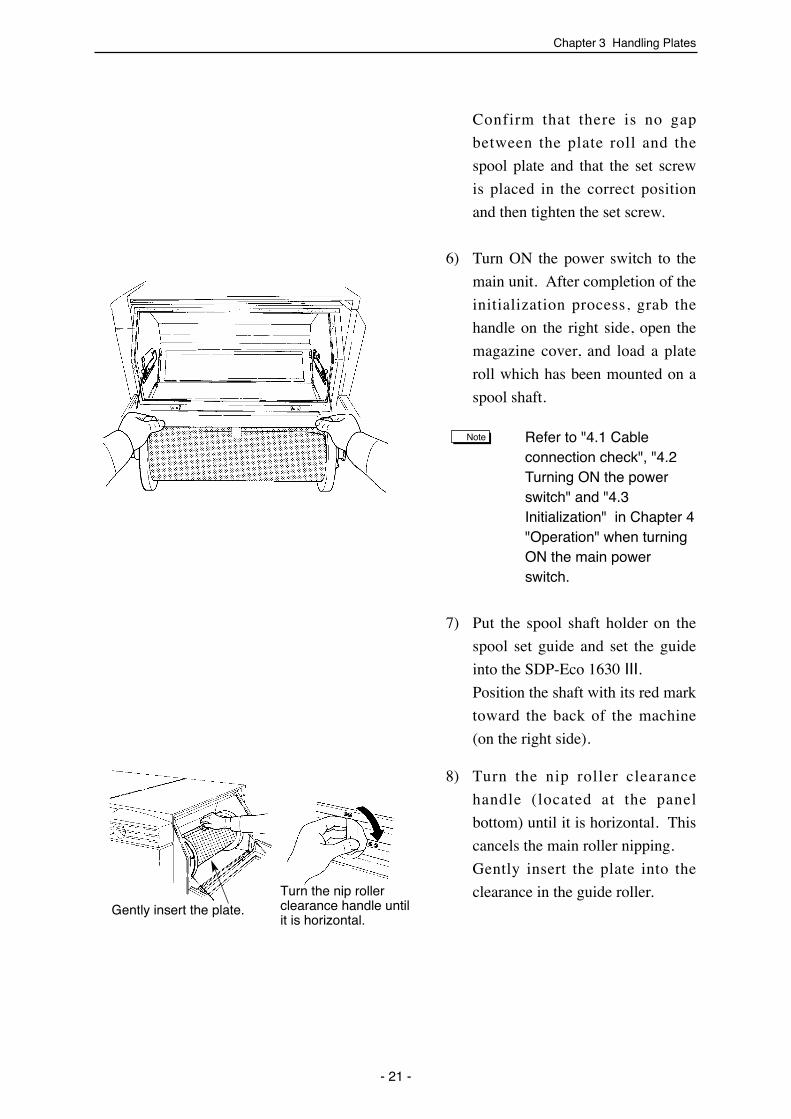
6) Turn ON the power switch to the
main unit. After completion of the
initialization process, grab the
handle on the right side, open the
magazine cover, and load a plate
roll which has been mounted on a
spool shaft.
Refer to "4.1 Cableconnection check", "4.2Turning ON the powerswitch" and "4.3Initialization" in Chapter 4"Operation" when turningON the main powerswitch.
7) Put the spool shaft holder on the
spool set guide and set the guide
into the SDP-Eco 1630 III.
Position the shaft with its red mark
toward the back of the machine
(on the right side).
8) Turn the nip roller clearance
handle (located at the panel
bottom) until it is horizontal. This
cancels the main roller nipping.
Gently insert the plate into the
clearance in the guide roller.
Note
- 21 -
Gently insert the plate.Turn the nip rollerclearance handle untilit is horizontal.
SDP-Eco1630 III USERS MANUAL
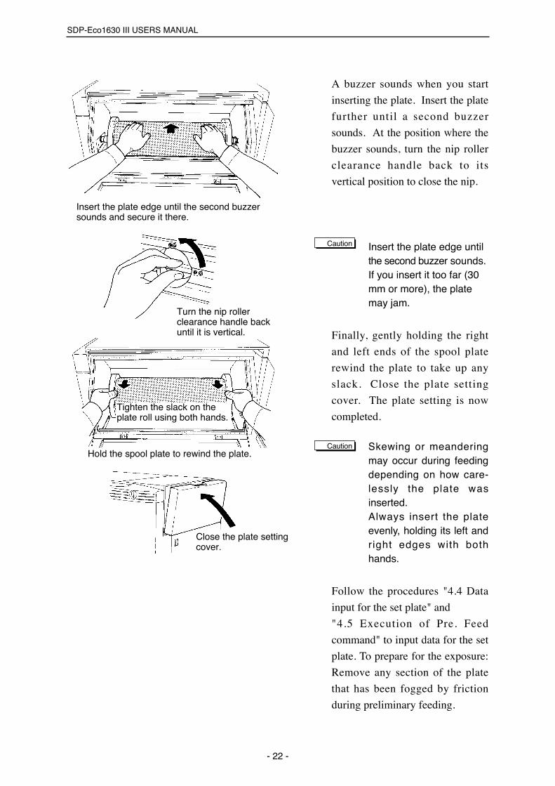
A buzzer sounds when you start
inserting the plate. Insert the plate
further until a second buzzer
sounds. At the position where the
buzzer sounds, turn the nip roller
clearance handle back to its
vertical position to close the nip.
Insert the plate edge untilthe second buzzer sounds.If you insert it too far (30mm or more), the platemay jam.
Finally, gently holding the right
and left ends of the spool plate
rewind the plate to take up any
slack. Close the plate setting
cover. The plate setting is now
completed.
Skewing or meanderingmay occur during feedingdepending on how care-lessly the plate wasinserted.Always insert the plateevenly, holding its left andright edges with bothhands.
Follow the procedures "4.4 Data
input for the set plate" and
"4.5 Execution of Pre. Feed
command" to input data for the set
plate. To prepare for the exposure:
Remove any section of the plate
that has been fogged by friction
during preliminary feeding.
Caution
Caution
- 22 -
Hold the spool plate to rewind the plate.
Tighten the slack on the plate roll using both hands.
Close the plate settingcover.
Insert the plate edge until the second buzzersounds and secure it there.
Turn the nip rollerclearance handle backuntil it is vertical.
Chapter 3 Handling Plates
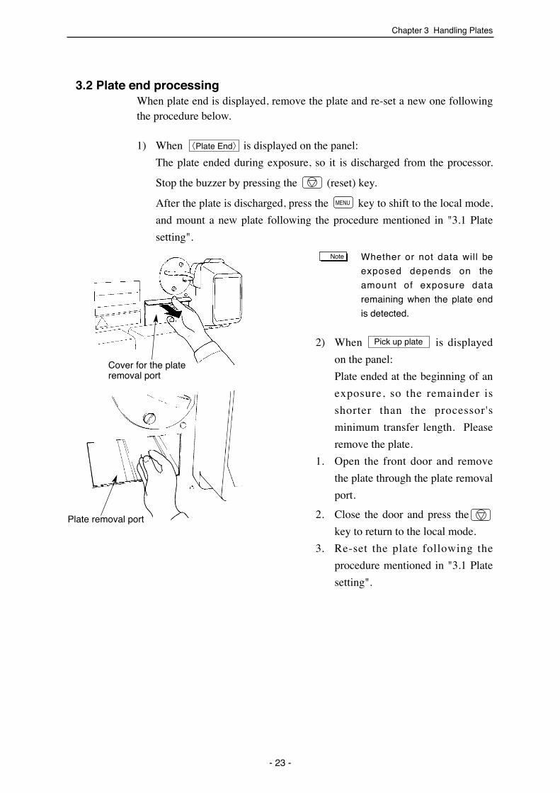
3.2 Plate end processingWhen plate end is displayed, remove the plate and re-set a new one followingthe procedure below.
1) When is displayed on the panel:
The plate ended during exposure, so it is discharged from the processor.
Stop the buzzer by pressing the (reset) key.
After the plate is discharged, press the key to shift to the local mode,
and mount a new plate following the procedure mentioned in "3.1 Plate
setting".
Whether or not data will be
exposed depends on the
amount of exposure data
remaining when the plate end
is detected.
2) When is displayed
on the panel:
Plate ended at the beginning of an
exposure, so the remainder is
shorter than the processor's
minimum transfer length. Please
remove the plate.
1. Open the front door and remove
the plate through the plate removal
port.
2. Close the door and press the
key to return to the local mode.
3. Re-set the plate following the
procedure mentioned in "3.1 Plate
setting".
Pick up plate
Note
MENU
〈Plate End〉
- 23 -
Cover for the plateremoval port
Plate removal port

SDP-Eco1630 III USERS MANUAL
- 24 -
Chapter 4 Operation
The SDP-Eco 1630 III is a SCSI device. Turn ON the power switch for this
machine first, and complete its initialization routine. Then turn ON the
power switch to the host computer (RIP computer).
Be sure to turn OFF the power switch to the host computer (RIP computer)
when turning OFF the power switch for this machine.
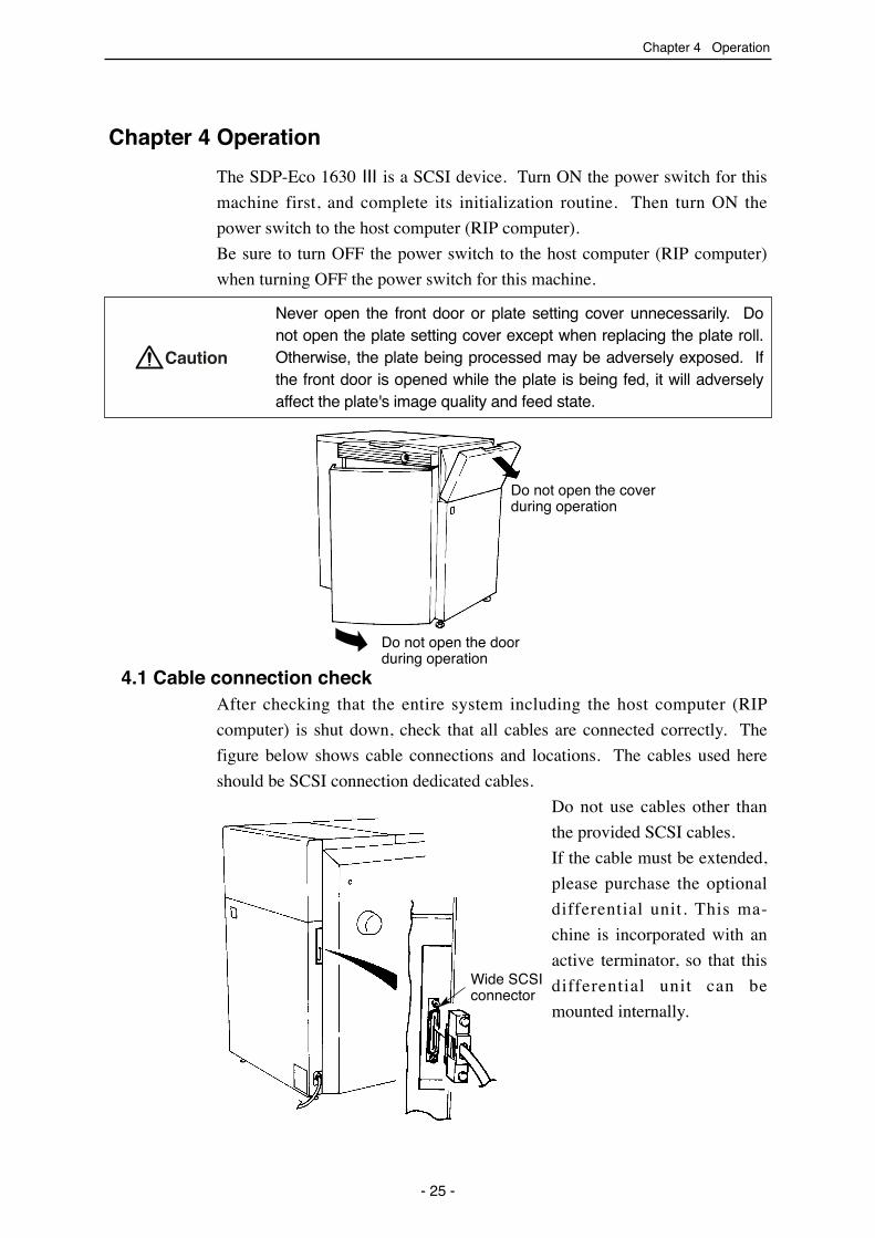
Never open the front door or plate setting cover unnecessarily. Donot open the plate setting cover except when replacing the plate roll.Otherwise, the plate being processed may be adversely exposed. Ifthe front door is opened while the plate is being fed, it will adverselyaffect the plate's image quality and feed state.
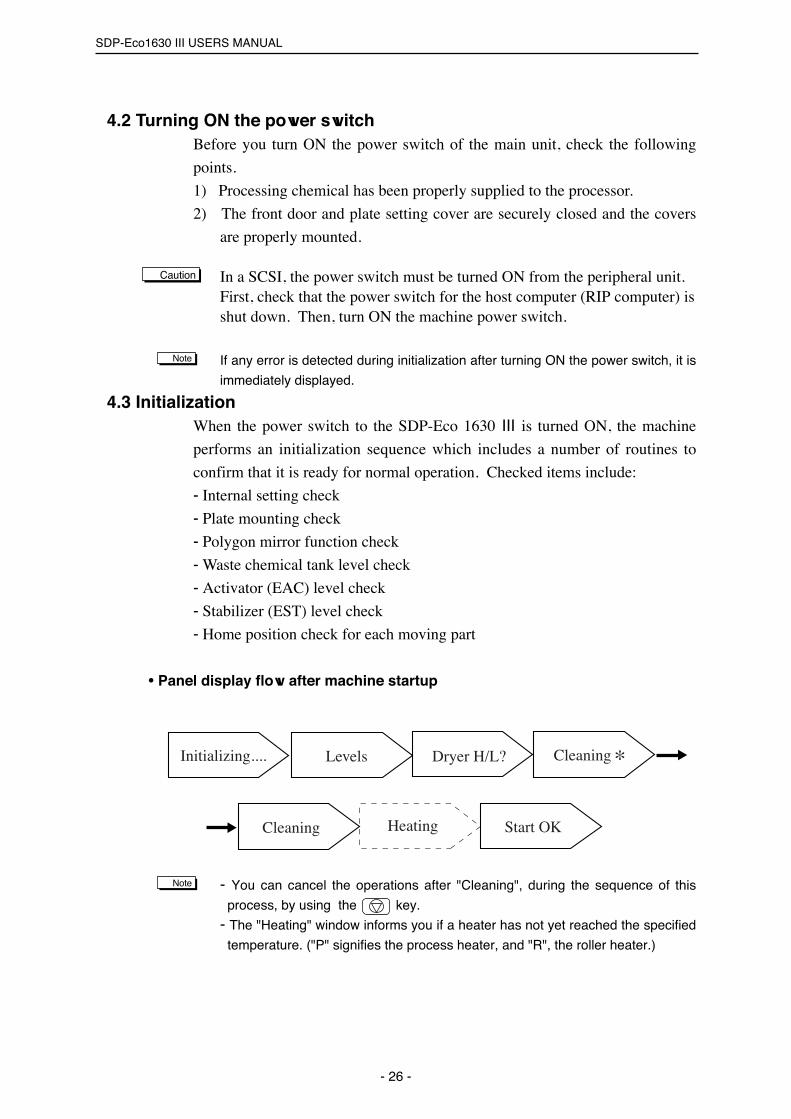
4.1 Cable connection checkAfter checking that the entire system including the host computer (RIP
computer) is shut down, check that all cables are connected correctly. The
figure below shows cable connections and locations. The cables used here
should be SCSI connection dedicated cables.
Do not use cables other than
the provided SCSI cables.
If the cable must be extended,
please purchase the optional
differential unit. This ma-
chine is incorporated with an
active terminator, so that this
differential unit can be
mounted internally.
Chapter 4 Operation
- 25 -
Caution
Wide SCSIconnector
Do not open the coverduring operation
Do not open the doorduring operation
SDP-Eco1630 III USERS MANUAL
4.2 Turning ON the power switchBefore you turn ON the power switch of the main unit, check the following
points.
1) Processing chemical has been properly supplied to the processor.
2) The front door and plate setting cover are securely closed and the covers
are properly mounted.
In a SCSI, the power switch must be turned ON from the peripheral unit.First, check that the power switch for the host computer (RIP computer) isshut down. Then, turn ON the machine power switch.
If any error is detected during initialization after turning ON the power switch, it is
immediately displayed.
4.3 InitializationWhen the power switch to the SDP-Eco 1630 III is turned ON, the machine
performs an initialization sequence which includes a number of routines to
confirm that it is ready for normal operation. Checked items include:
- Internal setting check
- Plate mounting check
- Polygon mirror function check
- Waste chemical tank level check
- Activator (EAC) level check
- Stabilizer (EST) level check
- Home position check for each moving part
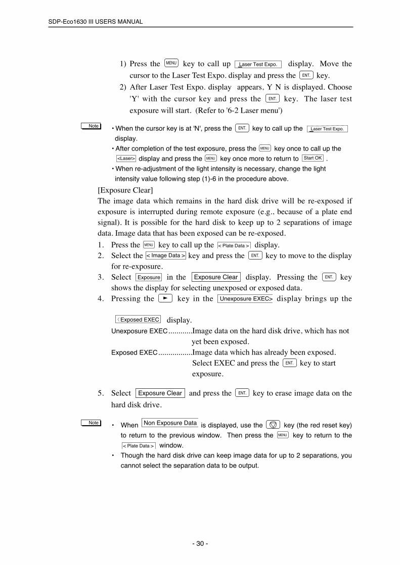
• Panel display flow after machine startup
- You can cancel the operations after "Cleaning", during the sequence of this
process, by using the key.
- The "Heating" window informs you if a heater has not yet reached the specified
temperature. ("P" signifies the process heater, and "R", the roller heater.)
Note
Levels Dryer H/L?
Cleaning Heating Start OK
Initializing.... Cleaning
Note
Caution
- 26 -

4.4 Data input for the set plate (This procedure is necessary when loading the plate.)
(1) Press the key to display the .
(2) Press the key to display , which is a lower
level of the menu.
(3) Use the key to select the data registration number, plate type, plate
width, or length of plate roll, then press the key to flash the cursor
(indicating mode change).
(4) Press the key after changing the data using the or key.
• Input the plate data and press the key. Press the key once to call
up the display and press the key once more to call up the display and switch to the on-line mode.
(Example)1) Selection of Data Memory Channel (From M0 to M3)
Press the key in order to start the
cursor key flashing and select M0 to
M9 using the key or the
key. Press the key to register the
data channel.2) Selection of plate type (From F100 to F175)
Press the key or the key to
move the cursor to the F100 display
(plate type). Press the key to
start the cursor flashing. Select the
plate type (F175, R175) using the
key or the key and press
the key to register the plate type.3) Selection of the plate width (From 404 to 414)
Press the key or the key to
move the cursor to the 404 display
(plate width). Press the key to
start the cursor flashing. Select the
plate width using the key or the
key and press the key to
register the plate width.
����
����
����
����
����
����
Start OK
MENU< Plate Data >
MENU����Note
����
< Plate Data >
M0 R 1 7 5 414 00m����
< Plate Data >MENU
Chapter 4 Operation
- 27 -
M0 F175 414 61m
M3 F100 404 37m If settingM3
Cursor
M3 F100 404 37m
M3 F175 404 61m
M3 F175 404 61m
M3 F175 414 61m
����
SDP-Eco1630 III USERS MANUAL
- 28 -
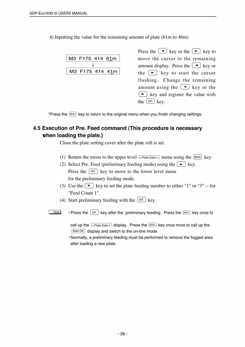
4) Inputting the value for the remaining amount of plate (61m to 46m)
Press the key or the key to
move the cursor to the remaining
amount display. Press the key or
the key to start the cursor
flashing. Change the remaining
amount using the key or the
key and register the value with
the key.
*Press the key to return to the original menu when you finish changing settings.
4.5 Execution of Pre. Feed command (This procedure is necessary when loading the plate.)
Close the plate setting cover after the plate roll is set.
(1) Return the menu to the upper level menu using the key.
(2) Select Pre. Feed (preliminary feeding mode) using the key.
Press the key to move to the lower level menu
for the preliminary feeding mode.
(3) Use the key to set the plate feeding number to either "1" or "3" -- for
"Feed Count 1".
(4) Start preliminary feeding with the key.
• Press the key after the preliminary feeding. Press the key once to
call up the display. Press the key once more to call up the
display and switch to the on-line mode.
• Normally, a preliminary feeding must be performed to remove the fogged area
after loading a new plate.
Start OK
MENU< Plate Data >
MENU����Note
����
����
MENU< Plate Data >
MENU
����
M3 F175 414 61m
M3 F175 414 41m

Chapter 4 Operation
- 29 -
4.6 ExposureThe machine has two exposure modes: remote exposure which performsexposure using data provided from the host computer, and local exposurewhich performs laser test exposure and re-exposure.
• Remote exposureAfter entering remote mode (ON LINE lamp is lit), give the exposurecommand through the host computer (RIP computer). While exposure is inprogress, "Exposing ***%" is displayed on the panel display. "***%"indicates the percentage currently exposed.[Display during remote exposure]The panel display changes as shown below during the exposure.
• Local exposure[Laser Test Expo.]
(1) Confirmation and input of the plate type, resolution and light intensity
1) Use the key to call up display.
2) Select using the key and press the key.
3) Press the key while is displayed.
4) Plate type, resolution and light intensity are displayed.
(Example) (F175 1200 dpi Light intensity 200)
5) Press the key to change the resolution. Select the desired
resolution from among 12 (1200 dpi), 15 (1500 dpi), 18 (1800 dpi)
and 24(2400dpi) using the key. Register the resolution using
the key.
6) Press the key to move the cursor to the light intensity value
display and then press the key.
7) Change the light intensity value using the key or the key.
Press the key to register the light intensity value.
Press the key to return to the previous menu if no change is necessary or
setting is discontinued.
(2) Exposure
MENUNote
����
����
����
����
F175 (12) 200
Laser Test Expo.����
����<Laser>
< Plate Data >MENU
Data transmission startData transmission end
Data Transferring
Image data exposure start Exposing 0%
Image data exposure end
Plate is being discharged
Exposing 100%
Discharging
Completion Complete
SDP-Eco1630 III USERS MANUAL
- 30 -
1) Press the key to call up display. Move the
cursor to the Laser Test Expo. display and press the key.
2) After Laser Test Expo. display appears, Y N is displayed. Choose
'Y' with the cursor key and press the key. The laser test
exposure will start. (Refer to '6-2 Laser menu')
• When the cursor key is at 'N', press the key to call up the
display.
• After completion of the test exposure, press the key once to call up the
display and press the key once more to return to .
• When re-adjustment of the light intensity is necessary, change the light
intensity value following step (1)-6 in the procedure above.
[Exposure Clear]The image data which remains in the hard disk drive will be re-exposed ifexposure is interrupted during remote exposure (e.g., because of a plate endsignal). It is possible for the hard disk to keep up to 2 separations of imagedata. Image data that has been exposed can be re-exposed.
1. Press the key to call up the display.2. Select the key and press the key to move to the display
for re-exposure.3. Select in the display. Pressing the key
shows the display for selecting unexposed or exposed data.4. Pressing the key in the display brings up the
display.Unexposure EXEC............Image data on the hard disk drive, which has not
yet been exposed.Exposed EXEC.................Image data which has already been exposed.
Select EXEC and press the key to start exposure.
5. Select and press the key to erase image data on the
hard disk drive.
• When is displayed, use the key (the red reset key)
to return to the previous window. Then press the key to return to the
window.
• Though the hard disk drive can keep image data for up to 2 separations, you
cannot select the separation data to be output.
< Plate Data >
MENU
Non Exposure DataNote
����Exposure Clear
����
〈������� ���
Unexposure EXEC>
����Exposure ClearExposure
����< Image Data >
< Plate Data >MENU
Start OKMENU<Laser>
MENU
Laser Test Expo.����Note
����
����
Laser Test Expo.MENU

Chapter 4 Operation
4.7 Processor sectionThe processing chemicals are applied to the plate while it is being transferred
in the SDP-Eco 1630 III's built-in processor section. The processor section
also includes a final rinsing process which cleans the developed plates and
thus reduces paper media waste (from processing chemical stains) at the start
of printing.
You must thoroughly read "1.3 Handling processing chemicals".
• Preparing and pouring processing chemical
1) Fasten a replenishment cap on the replenisher bottle which contains the
processing chemical and set it in the tank.
Be sure to set the bottle in the appropriate tank since the SLM-EACand SLM-EST cause different (opposing) effects.
• Processing chemical replenishment
As the processing chemical decreases, the liquid level in the tank goes down
and finally the "Empty EST" or "Empty EAC" message appears on the display
(accompanied by a buzzer sound). Replenish the processing chemical
following the procedure below.
Replenish the processing chemical and replace the processing bottle
following the procedure below.
1) Press the key to turn off the buzzer.
2) Open the front door.
3) Add processing chemical from the container (10 liters) to the replenisher
bottle.
4) Put the cap back on the replenisher bottle and set it in the tank.
Caution
- 31 -
Caution
Rinse waterreplenisherbottle
Washing tank
Wastewater hose
SLM-ESTdrainagehose
SLM-ESTreplenisherbottle
Processor rack
SLM-ESTprocessingchemical tank
SLM-EACreplenisherbottle
SLM-EACprocessingchemical tank
SLM-EACdrainagehose
Cap
Waste chemical vat
Waste chemical tank
SDP-Eco1630 III USERS MANUAL
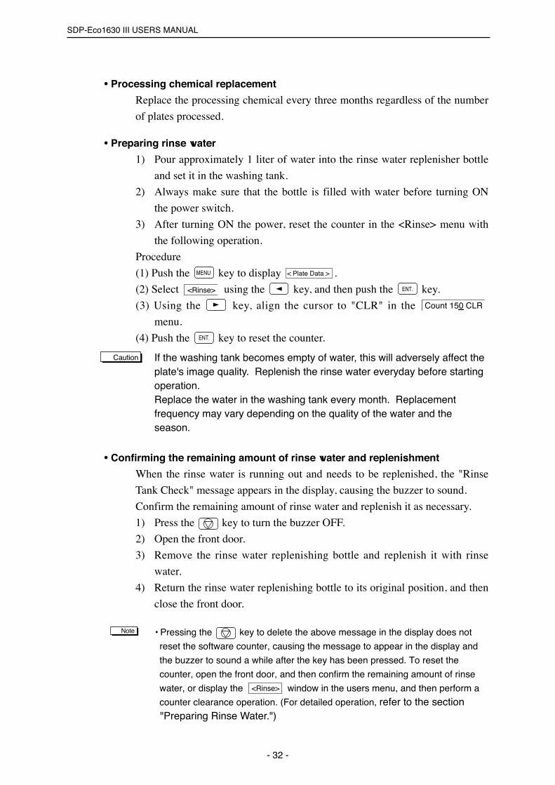
• Processing chemical replacement
Replace the processing chemical every three months regardless of the number
of plates processed.
• Preparing rinse water
1) Pour approximately 1 liter of water into the rinse water replenisher bottle
and set it in the washing tank.
2) Always make sure that the bottle is filled with water before turning ON
the power switch.
3) After turning ON the power, reset the counter in the <Rinse> menu with
the following operation.
Procedure
(1) Push the key to display .
(2) Select using the key, and then push the key.
(3) Using the key, align the cursor to "CLR" in the
menu.
(4) Push the key to reset the counter.
If the washing tank becomes empty of water, this will adversely affect theplate's image quality. Replenish the rinse water everyday before startingoperation.Replace the water in the washing tank every month. Replacementfrequency may vary depending on the quality of the water and theseason.
• Confirming the remaining amount of rinse water and replenishment
When the rinse water is running out and needs to be replenished, the "Rinse
Tank Check" message appears in the display, causing the buzzer to sound.
Confirm the remaining amount of rinse water and replenish it as necessary.
1) Press the key to turn the buzzer OFF.
2) Open the front door.
3) Remove the rinse water replenishing bottle and replenish it with rinse
water.
4) Return the rinse water replenishing bottle to its original position, and then
close the front door.
• Pressing the key to delete the above message in the display does not
reset the software counter, causing the message to appear in the display and
the buzzer to sound a while after the key has been pressed. To reset the
counter, open the front door, and then confirm the remaining amount of rinse
water, or display the window in the users menu, and then perform a
counter clearance operation. (For detailed operation, refer to the section "Preparing Rinse Water.")
<Rinse>
Note
Caution
����
Count 150 CLR
����<Rinse>
< Plate Data >MENU
- 32 -

Chapter 4 Operation
• If the output data is sent from the host computer to the recorder while the above warning is being issued, the warning disappears, executing output operation. After output operation has been completed, the warning message appears and the buzzer sounds again.
• Handling waste liquid
Scale lines indicating capacity are marked on the waste chemical tank.
Observe the scale line carefully and dispose of the processing chemical before
it reaches the 10-liter line.
When the waste chemical tank is full, the "Waste tank check" message appears
and a buzzer sounds. (Images cannot be read at this time.)
Dispose of the processing chemical following the procedure below.
1) Press the key to turn off the buzzer.
2) Remove the cap from the waste chemical tank and dispose of the waste
chemical in the tank.
3) Put the cap back on the now empty tank and put it back in the waste
chemical vat.
- The waste chemical tank weighs approximately 11 kilograms when itis full, so please be very careful when handling it. (Refer to "1.3Handling processing chemicals".)
- Be careful when handling the hose attached to the waste chemicalcap. Using a crimped or twisted hose can cause chemical leakage.
• If the machine is not used for a long period
Before deactivating the machine for a long time (7 days or more),always drain the water in the rinse water replenisher bottle.
If the machine has not been used for a long time, the processor rack roller may
stick and not rotate smoothly.
Follow the procedure below so that the processor rack roller will rotate
smoothly.
1) Open the front door.
2) Remove the replenisher bottle
from the tank.
3) Hold the handle in the processor
rack section and slightly pull out
the processor rack.
- 33 -
Caution
Handle Processor rack
Caution

SDP-Eco1630 III USERS MANUAL
- 34 -
4.8 Collecting exposed platesExposed plates are discharged into the plate receiving tray. The SDP-Eco
1630 II discharges plates image-side down. Adjust the length of the discharge
retainer arm to accommodate the maximum length of the plates used.
It is possible to continuously collect plates (up to 50 consecutive sheets).However, we cannot guarantee trouble-free collection of such largenumbers of plates if the machine is indiscriminately discharging plates ofdifferent lengths or if the plate type is frequently being changed.
4.9 Turning OFF the power supply and inspection at shutdown
Always, before shutting down the machine, press the power ON/OFF key to
perform the final inspection. When is displayed in the on-line mode,
press the key to return to the local mode and then press the power
ON/OFF key.
The required final inspection includes checking the chemical level in the
waste chemical tank and releasing the plate nip by turning the nip roller
clearance handle to its vertical position. Roller cleaning is also performed
during the final inspection. If this procedure is not followed, transfer errors
may occur or masters exposed on the following day may be stained or marred.
If this procedure is not followed, transfer errors may occur or plates exposed
on the following day may be stained or marred.
It is not necessary to turn ON/OFF the main power for a weekday shut-down.
For weekend inspections: at shut-down, first turn OFF the machine,
completely clean the roller, and finally turn OFF the main power supply (at
the breaker).
MENU
Start OK
Caution
4) To rotate the roller, turn the handle
in the direction indicated by the
arrow in the figure.
Rotate the roller with the handle.

Chapter 4 Operation
When shutting down the machine by pressing the power ON/OFF key, the
dehumidifying heater will automatically run unless the main power is also shut
down. The dehumidifying heater attached below the plate setting section inhibits
condensation in the machine by heating plates when humidity is high and
temperature is low. The low temperature keeps the machine away from fire
danger.
During the final inspection, do not open the front door until the display panel is turned off; otherwise the final inspection will stop in the middleof the operation.
Caution
Note
- 35 -

SDP-Eco1630 III USERS MANUAL
- 36 -

Chapter 5 Menus and panel displays
Chapter 5 Menus and panel displays
The display panel shows the performance status of the SDP-Eco 1630 III, its
error messages, etc.
5.1 User menu
- 37 -

SDP-Eco1630 III USERS MANUAL
Operation status
[Remote and local]
In the remote mode, it is possible to expose data transferred from the host
computer (RIP computer). In the local mode, exposure data from the host
computer (RIP computer) cannot be accepted.
The local mode includes a "User menu" (including user maintenance
functions) and a "Maintenance menu".
[User menu]
The "User menu" provides the basic commands necessary to operate the
machine.
[Maintenance menu]
If a command or a dialog for a command that is not included in the User
menu list appears, immediately press the key several times to return
to the User menu. (Do NOT press the key.)
This menu is used to adjust the SDP-Eco 1630 III.
[Standby mode]
In remote mode, if no command is sent to the machine for 10 minutes, it
enters the standby mode.
The standby mode will be canceled whenever a command is given or
when any key on the panel except the key is pressed.
Recovery time will differ depending on whether the machine has been in standby
mode for more than 10 minutes. If the machine was left idle for more than 10
minutes, recovery will take longer because a cleaning routine is performed for
the processor roller.
[Auto power OFF]
When this machine is left in the local mode for two hours, a cleaning
routine is performed for the processor roller and the power is turned OFF
automatically.
Note
����
����
- 38 -
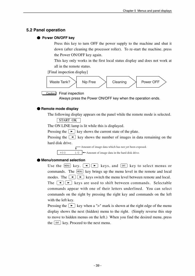
5.2 Panel operation
Power ON/OFF key
Press this key to turn OFF the power supply to the machine and shut it
down (after cleaning the processor roller). To re-start the machine, press
the Power ON/OFF key again.
This key only works in the first local status display and does not work at
all in the remote status.
[Final inspection display]
Final inspectionAlways press the Power ON/OFF key when the operation ends.
Remote mode display
The following display appears on the panel while the remote mode is selected.
START OK
The ON LINE lamp is lit while this is displayed.
Pressing the key shows the current state of the plate.
Pressing the key shows the number of images in data remaining on the
hard disk drive.
Menu/command selection
Use the key, keys, and key to select menus or
commands. The key brings up the menu level in the remote and local
modes. The keys switch the menu level between remote and local.
The keys are used to shift between commands. Selectable
commands appear with one of their letters underlined. You can select
commands on the right by pressing the right key and commands on the left
with the left key.
Pressing the key when a ">" mark is shown at the right edge of the menu
display shows the next (hidden) menu to the right. (Simply reverse this step
to move to hidden menus on the left.) When you find the desired menu, press
the key. Proceed to the next menu.����
����
��������
Chapter 5 Menus and panel displays
- 39 -
Waste Tank? Nip Free��
Cleaning Power OFF
HDD 1/2
Amount of image data which has not yet been exposed.
Amount of image data in the hard disk drive.
Caution

SDP-Eco1630 III USERS MANUAL
Switch the mode between remote and local
Remote Mode Local Mode
Start OK Plate Data
Shift between commands (Example)
1st hierarchy Maintenance
2nd hierarchy Cutter Processor Ver SCSI-ID
Command execution
There are two types of commands: one which activates machine functions
such as preliminary feeding and cutter processor commands, and one which is
used, for example, to set numerical values.
For commands in which numerical values can be changed (Example:
Referring to P27 "4.4 Data input for the set plate")
Use the to move the cursor to the numerical value display. Press the
key to start the display flashing and change the displayed value. (In
some modes the numerical value display starts flashing from the time it is first
displayed.)
The or key increases/decreases a numerical value.
Press the key when the desired number appears.
If you wish to reset a value or interrupt the setting procedure, press the
key to return to the upper menu level without changing the currently set value
and re-start the setting procedure from the beginning by selecting the same
command.
For commands in which numerical values can not be changed (Example:
Referring to P28 "4.5 Execution of Pre. Feed command")
Use the to select the desired command. Then press the key to
execute it.
Repeatedly press the key until Start OK is displayed to return to the on-
line mode.
����
����
����
����
����
��������
����
- 40 -

Chapter 6 User menu
It is possible to set values affecting the machine's operation state from the user
menu. Note that some settings from the host computer are given priority and
they will be automatically changed if the host computer resets them.
Refer to '5.2 Panel operation' for details on key operation.
6.1 Plate data
The command is used to enter information on the plate to be
loaded.
Data channel
The data channel stores the plate information. 10 different sets of plate
parameter data can be stored (from M0 to M9). The plate information consists
of plate type, plate width, remaining amount, and the set laser (depends on the
resolution for the respective plate type).
Plate type
You can only use the following three types of plates.
Plate width
Each plate can be set to the following widths (displayed in mm).
〈����� ����〉
Note
Chapter 6 User menu
- 41 -
Plate model�
SDP-FRm175�
SDP-FR100�
SDP-RR175�
Panel display�
F175�
F100�
R175�
Remarks�Polyester base �
t 0.175 mm�Polyester base �
t 0.100 mm�Paper base �t 0.175 mm
����� ��������
����� ����� � ������ � ��������
F175 M1 404 60m
������ ����� � �����
����� ������� ����� ����� ��
SDP-Eco1630 III USERS MANUAL
Remaining amount of plate
The remaining amount of plate should be set in meter units when you use a
new plate.
The initial setting value is 0 meter.
The remaining amount of plate is shown in 1 meter increments (0 to 75
meters) in the remote mode display
The remaining amount value is calculated by subtracting the exposed plate
length from the plate length set by the operator. The plate length for
preliminary feeding is also subtracted.
However, the accuracy of the remaining length measurement is not
guaranteed. Please regard this value simply as a reference guide.
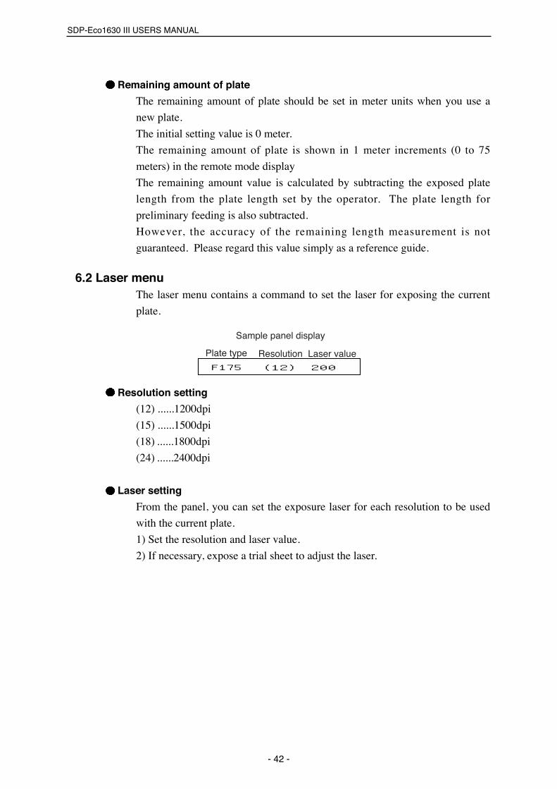
6.2 Laser menuThe laser menu contains a command to set the laser for exposing the current
plate.
Resolution setting
(12) ......1200dpi
(15) ......1500dpi
(18) ......1800dpi
(24) ......2400dpi
Laser setting
From the panel, you can set the exposure laser for each resolution to be used
with the current plate.
1) Set the resolution and laser value.
2) If necessary, expose a trial sheet to adjust the laser.
- 42 -
����� ���� ������ ���� �����
F175 (12) 200
������ �� �� ������
Chapter 6 User menu
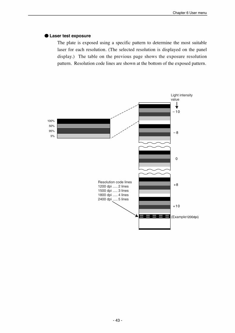
Laser test exposure
The plate is exposed using a specific pattern to determine the most suitable
laser for each resolution. (The selected resolution is displayed on the panel
display.) The table on the previous page shows the exposure resolution
pattern. Resolution code lines are shown at the bottom of the exposed pattern.
- 43 -
(Example1200dpi)
Resolution code lines1200 dpi ..... 2 lines1500 dpi ..... 3 lines1800 dpi ..... 4 lines2400 dpi ..... 5 lines
Light intensity value
+10
+8
0
8
10
100%
50%
95%
5%
SDP-Eco1630 III USERS MANUAL
6.3 Pre. Feed menuWhenever you set a new plate, a "Pre. Feed" operation is performed to
eliminate any fogged sections at the leading edge.
From the display panel, you can select whether to feed 1 or 3 sheets for this
operation. The length of each sheet is 500 mm, so if you perform a 3-sheet
preliminary feed, 1500 mm of plate will be cut, fed and disposed of.
If there are still darkened or fogged areas on the plate, perform another
preliminary feed.
6.4 Image Data menuThe SDP-Eco 1630 III incorporates a hard disk drive buffer to avoid idle time
due to differences in calculation speed between itself and the host, and to
enable quick re-exposure after an exposure was interrupted (e.g., if you use
the stop key or the plate ends).
Data written in the hard disk drive can be exposed or erased in the local mode.
Select the "Exposure" command to expose the data and the "Clear" command
to erase it.
6.5 Mode menuIn this menu, you can operate the punch (option), select a dryer level, and set
the buzzer response for different key operations.
Set the punch to ON to punch plates before image exposure or set it to OFF if
punching is not necessary.
If the machine does not contain a punch unit, the "Un-mounted" message
appears.
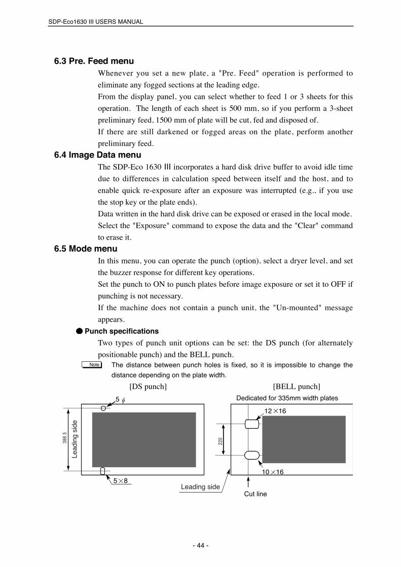
Punch specifications
Two types of punch unit options can be set: the DS punch (for alternately
positionable punch) and the BELL punch.The distance between punch holes is fixed, so it is impossible to change the
distance depending on the plate width.
[DS punch] [BELL punch]
Note
- 44 -
220
Lead
ing
side
Leading side
386.
5
Cut line
Dedicated for 335mm width plates
12 16
10 165 8
5

Chapter 6 User menu
Dryer level selection
When setting the dryer temperature, you can select either automatic or manual
(Hi or Low). Select the temperature setting which suits your plate type and
the environmental conditions.
If you select automatic setting, the dryer temperature will be set to "Hi" for
FR100 and FRm175 plates, and "Low" for RR175.
Stand-by mode ON/OFF
Either activate (ON) or deactivate (OFF) the stand-by mode as follows.
ON: The Stand-by mode is active.
OFF: The Stand-by mode is inactive.
6.6 Maintenance menuThis menu is used when a plate is jammed, the processor is operating, etc.
Cutter
If a plate is jammed in the machine, the cutter can often be used to help free
and discharge the plate. The cutter returns to its original position after cutting
a plate.
Processor
The processor can be activated independently of the exposure unit.
VER
This command displays the version numbers of the software in the machine
(MCON software which controls SDP-Eco 1630 III operations and SCOM
software which controls the SCSI interface).
SCSI-ID
This command allows you to set/reset SCSI-IDs. Note that after changing a
SCSI-ID setting, you must turn OFF the power and reboot the entire system
including the SDP-Eco 1630 III itself.
6.7 RinseThe machine is provided with the software counter that functions to warn
operators when the rinse water lowers than the designated level. The warning
is issued in a message and does not prevent output operations.
• When the recorder has received the exposure data from the host computer
(RIP computer) while the "Rinse Tank Check" message is displayed, this
message disappears, and then the exposure is performed. After the exposure
has been finished, the "Rinse Tank Check" message is displayed again.
Note
- 45 -

SDP-Eco1630 III USERS MANUAL
• The alarm function in this machine has been set to OFF before shipment at
the factory.
(Settings 000 = OFF)
• The consumption rate of rinse water may be different depending on the
settings in the machine. Set the consumption rate with the following
procedure.
[Procedure] (In cases where the current values are changed to "150".)
(1) Push the key to display the window.
(2) Select with the key, and then push the key.
(3) When is displayed, make sure that the cursor is placed
under the setting, and then push the key.
(4) Push either the key (Increase) or the key (Decrease) to set the
settings to "150".
(5) After changing the setting, push the key to confirm the setting.
(6) Push the key two times to display the window.
Use "120 to 160" as a reference value. Adjust the rate of rinse water reduction
depending on the installation conditions of the machine.
(Adjustable range: 50 to 300. Note that using "000" deactivates this function.)
[Notes for adjustment]
(1) When the "Rinse Tank Check" message is displayed.
If the replenishing bottle is empty, decrease the setting.
If there is a lot of rinse water left in the bottle, increase the setting.
(2) To deactivate the software counter function, use "000" as a setting value.
Be sure to reset the counter by "CLR" after you have adjusted the setting.
Note
〈����� ����〉 MENU
����
����
Count 150 CLR
����〈�����〉
〈����� ����〉 MENU
- 46 -

Chapter 7 Maintenance
Chapter 7 Maintenance
7.1 Cutter blade replacementIf the edge of the cutter becomes notched, chipped or curved after cutting a
plate, the blade must be replaced.
The cutter blade should be replaced regularly both to prevent transfer jams
and problems due to cutting errors, and to maximize the machine's overall
performance.
Always replace the blade after cutting two plate rolls and/or every 30 days
regardless of the number of plates cut.
Replacement procedure
1) Turn OFF the power switch.
2) Open the front door.
3) Remove the cutter unit cover.
4) Insert the cutter blade between
the cutter blade guides (upper
and lower) in the direction
indicated by the arrow in the
figure and secure it in the
designated position.
Use the accompanyingcutter blade or NT cutterblades (85 mm), whichare commercially available.Align the back side of thecutter with the cuttercarriage guide andtighten the set screw witha coin.
5) Return the cutter unit, cover, and
front door to their original
positions. Turn ON the power
switch and check the cutter's
performance in the maintenance
mode.
Always be careful when handling the cutter blade. Wear safety glovesto protect your hands from being cut.
Caution
- 47 -
Remove thecutter unitcover.
Cutter carriage
Set screw
Back side of cutter bladeCutter blade guide (upper)
Cutter blade guide (lower)
Cutter guide
Caution
Cutter blade replacementprocedure label

SDP-Eco1630 III USERS MANUAL
7.2 Cylindrical lens cleaningThe SDP-Eco 1630 III incorporates a
highly accurate optical system in
which the lens is positioned
extremely close to the exposed
surface.
Therefore, if the lens is soiled with
dirt or dust due to environmental
conditions, for example, it may show
up as a vertical line (white or black).
1) If a vertical line appears, open the
front door, loosen the two screws on
the cylindrical lens unit, and remove
the entire unit by gently pulling it out
toward the operator.
2) Inspect the lens under a bright
fluorescent light to check its
cleanliness and, if there is any dirt or
dust, clean it off with a blower.
Do not use compressedair when cleaning thelens.
3)Never touch the lens with your hand
or any kind of tool. These lens can
be easily scratched and may require
replacement.
The plate will be foggedafter you replace thelens. Before the nextoperation, feed onesheet through themachine.
4)Re-assemble the cylindrical lens unit,
reversing the previous procedure. Be
sure to firmly re-insert the unit as far
back as it will go into the machine
chassis.
Caution
Caution
- 48 -
Cylindrical lens
Clean it off with a blower
Remove theentire unitby gentlypulling it outtoward theoperator.
Cylindrical lensunit
Screw
Chapter 7 Maintenance
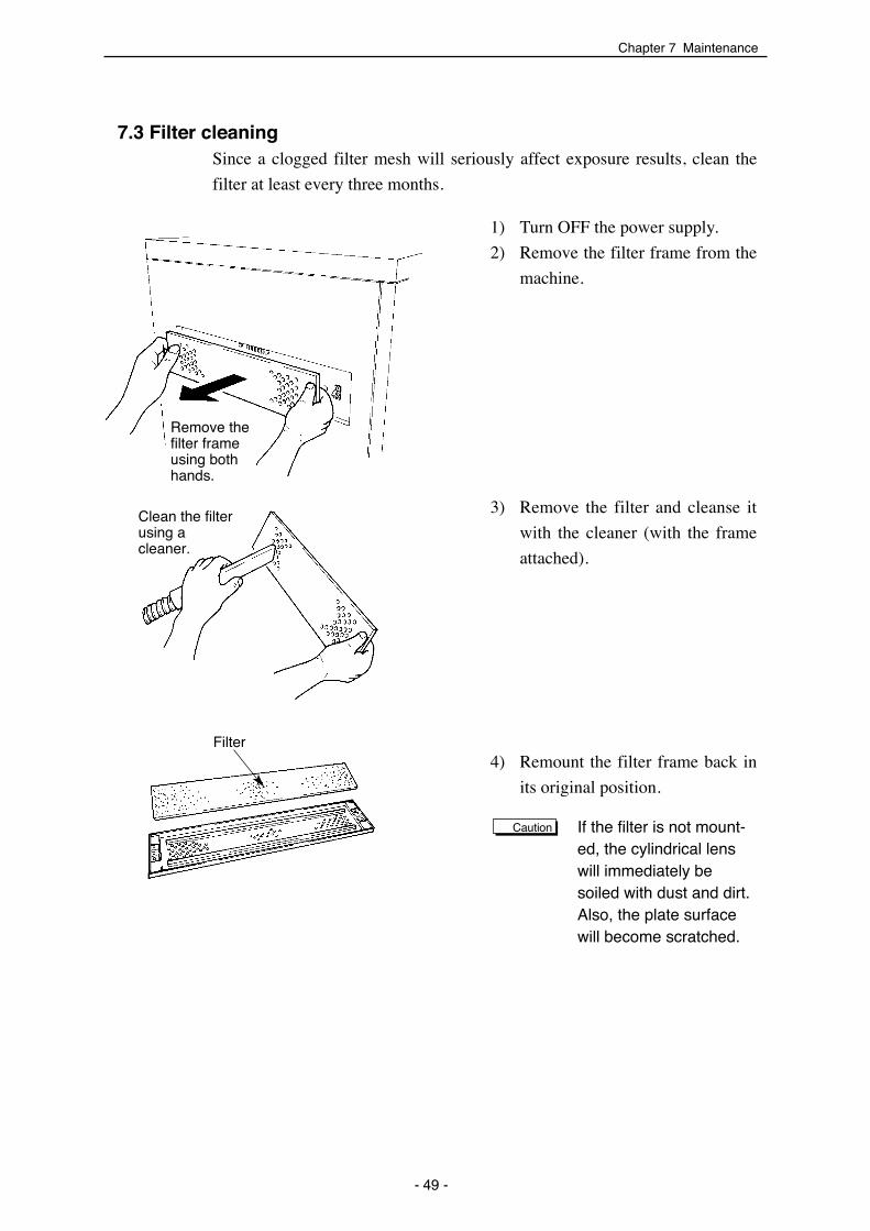
7.3 Filter cleaningSince a clogged filter mesh will seriously affect exposure results, clean the
filter at least every three months.
1) Turn OFF the power supply.
2) Remove the filter frame from the
machine.
3) Remove the filter and cleanse it
with the cleaner (with the frame
attached).
4) Remount the filter frame back in
its original position.
If the filter is not mount-ed, the cylindrical lenswill immediately besoiled with dust and dirt.Also, the plate surfacewill become scratched.
Caution
- 49 -
Remove thefilter frameusing bothhands.
Clean the filterusing acleaner.
Filter

SDP-Eco1630 III USERS MANUAL
- 50 -
7.4 Punch dust removalWhen the punch unit (option) is mounted, it is necessary to periodically
remove the accumulated punch dust. Too much punch dust may cause
trouble. Be sure to remove the punch dust following the steps below.
If the "Punch Dust Check" warning message is displayed on theoperation panel, be sure to remove the punch dust (punching has beenperformed more than 1000 times).
1) Open the plate setting cover and
turn the upper nip roller handle
until it is horizontal to rewind the
plate. Remove the plate.
2) Remove the punch box cover at
the bottom of the entrance roller
where the plate is inserted. The
cover is only attached with a
magnet, so it can be easily
removed by manually pulling on
it.
3) The punch dust is collected in the
punch box. Carefully remove the
box and discard the dust.
4) Re-assemble the punch unit by
reversing the above procedure.
Caution
Remove the plate
Punch box cover
Remove the box
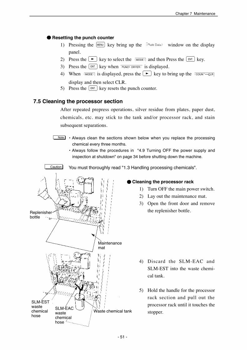
7.5 Cleaning the processor section After repeated prepress operations, silver residue from plates, paper dust,
chemicals, etc. may stick to the tank and/or processor rack, and stain
subsequent separations.
• Always clean the sections shown below when you replace the processing
chemical every three months.
• Always follow the procedures in "4.9 Turning OFF the power supply and
inspection at shutdown" on page 34 before shutting down the machine.
You must thoroughly read "1.3 Handling processing chemicals".
Cleaning the processor rack
1) Turn OFF the main power switch.
2) Lay out the maintenance mat.
3) Open the front door and remove
the replenisher bottle.
4) Discard the SLM-EAC and
SLM-EST into the waste chemi-
cal tank.
5) Hold the handle for the processor
rack section and pull out the
processor rack until it touches the
stopper.
Caution
Note
Resetting the punch counter
1) Pressing the key bring up the window on the display
panel.
2) Press the key to select the and then Press the key.
3) Press the key when is displayed.
4) When is displayed, press the key to bring up the
display and then select CLR.5) Press the key resets the punch counter.����
〈COUNT••••CLR〈MODE〉
PUNCH DRYER〉����
����〈MODE〉
〈Plate Data〉 MENU
Chapter 7 Maintenance
- 51 -
Maintenancemat
Waste chemical tank
Replenisherbottle
SLM-ESTwastechemicalhose
SLM-EACwastechemicalhose
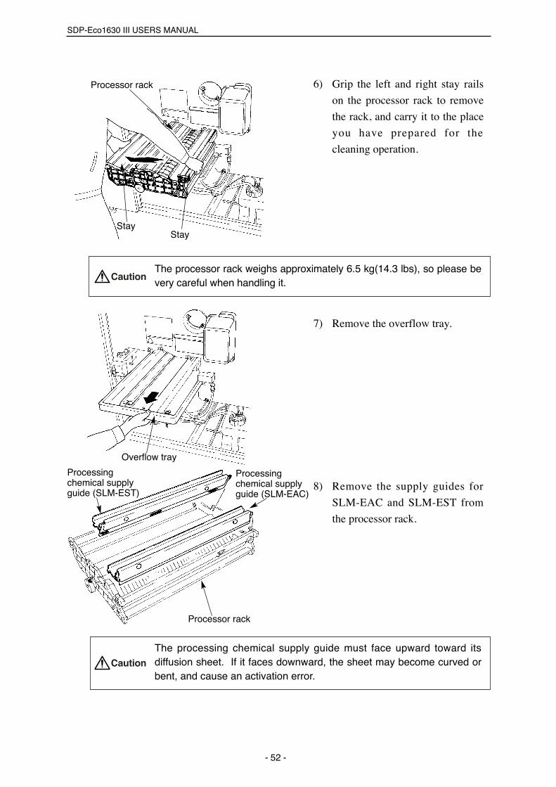
6) Grip the left and right stay rails
on the processor rack to remove
the rack, and carry it to the place
you have prepared for the
cleaning operation.
The processor rack weighs approximately 6.5 kg(14.3 lbs), so please bevery careful when handling it.
7) Remove the overflow tray.
8) Remove the supply guides for
SLM-EAC and SLM-EST from
the processor rack.
The processing chemical supply guide must face upward toward itsdiffusion sheet. If it faces downward, the sheet may become curved orbent, and cause an activation error.
SDP-Eco1630 III USERS MANUAL
- 52 -
Overflow tray
Processor rack
Processingchemical supplyguide (SLM-EST)
Processingchemical supplyguide (SLM-EAC)
Caution
Processor rack
StayStay
Caution

Chapter 7 Maintenance
- 53 -
If the diffusion sheet iscurved or bent, loosen thesheet retainer on theprocessing chemical supplyguide and replace thesheet with a stand-arddiffusion sheet.
9) Wash the processing chemical supply guide diffusion sheets (SLM-EAC
x 2, SLM-EST x 1) with water and wipe them dry with a clean cloth.
10) Wash the processor rack and overflow tray with water.
The synthetic rubber used for the processor rack roller is susceptible to high
temperatures, so don't wash it with water that is warmer than 40˚C. Never use
detergent or other cleaning solutions.
11) Re-attach the supply guides to the processor rack.
Cleaning the processing chemical
tank and filter
Always clean theprocessing chemical tankand filter when you replacethe processing chemicalevery three months or afterprocessing 1000m2 ofplates.
1) Lift the upper cover for the
processing tank and pull out the
tank.
The upper cover for SLM-EAC is attached to a panel heater, so itmay be very hot. Be very careful when performing this operation.Sensor cords are connected to the upper cover. Do not forcibly pullat these cords.
Note
Note
Note
Diffusion sheet
Diffusion sheet
SLM-ESTSLM-EAC
Upper cover
Processing tank
Caution
Brush bar

2) Remove the filter installed in the
processing chemical tank.
3) Wash the filter and processing
chemical tank with water.
4) Re-install the filter in the
processing chemical tank.
Pull the cylindrical filter down
over the filter attachment
section in the processing
chemical tank.
The filter must always be installed. If you attempt to operate thismachine without a filter, the processing chemical supply pipe willbecome clogged and seriously affect subsequent results.
5) Return the processing chemical tank to its original position and replace
its upper cover.
Since the heater is attached to the tank's upper cover, be sure thecover is properly seated into the top of the tank to prevent the heaterfrom overheating.
Cleaning the processing chemical
supply pipe
Always clean the processingchemical supply pipe whenyou replace the processingchemical every three months.
1) Remove the processing chemical
supply pipes (for SLM-EAC,
rinse water, and SLM-EST).
2) Remove the supply hose from the
processing chemical supply pipe.
3) Clean the processing chemical
supply pipe.
Note
Note
SDP-Eco1630 III USERS MANUAL
- 54 -
Supply hoseSupply hose
Processingchemical supplypipe (SLM-EST)
Processingchemical supplypipe (SLM-EAC)
Processingchemical supplypipe (rinse water)
Supply hose Processing chemicalsupply pipe
Caution
Caution
Filter

4) Attach the supply pipe to the
processing chemical supply hose.
5) Install the processing chemical
supply pipe.
When the processingchemical supply pipe isclogged, clean the piperegardless of the timeelapsed.
Cleaning the nip roller and exit roller
(upper)Always clean the rinse waternip roller and upper exit rollerafter processing 1000 platesor every month.
1) Loosen the set screw (with a
coin) to remove the left processor
rail.
2) Pull out the left processor rail
toward the operator side.
3) Lift up and remove the rinse
water nip roller.
The rinse water nip roller weighs approximately 2 kilograms, so pleasebe very careful when handling it.
Note
Caution
Chapter 7 Maintenance
- 55 -
Screw section
HoleHole
Processor rail (left)Set screw
Rinse water nip rollerExit roller (upper)
Caution

Slit
Processor rail (left)
Caution
SDP-Eco1630 III USERS MANUAL
4) Lift up and remove the upper exit roller.
5) Clean the rinse water nip roller and upper exit roller.
6) Wipe the rinse water nip roller until dry. Wring water lightly from the
upper exit roller. Re-attach both in their original positions.
Always attach the upper exit roller on the left.If it is mistakenly attached on the right, the plate might dry unevenly ora drying error might occur.
7) Re-attach the overflow tray in its
original position.
8) Insert the back side of the left
processor rail in the slit in the
side panel.
9) Secure the left processor rail
using the set screw.
Securely fix the set screw using a coin.
10) Re-attach the processor rack back in its original position.
Cleaning the exit roller (lower)
Always clean the rinse water
nip roller and upper exit roller
after processing 1000 plates
or every month.
1) Follow the previous steps from
"1)" through "4)" to clean the
upper exit roller as well as the
rinse nip roller. Leave the
machine with the upper exit
roller removed.
2) Drain the water in the washing
tank into the waste chemical
container.
Note
- 56 -
Caution
Rinse waterdrain hose
Container forwastechemical

Chapter 7 Maintenance
- 57 -
3) Remove the two set screws, and
then the roller fixing bracket
4) Remove the overflow tray.
5) Loosen the set screw to remove
the left tray rail.
6) Pull out the left tray rail toward
the operator side.
7) Slightly loosen the two set
screws for the washing tank
retainer using a coin.
8) Move the washing tank retainer
to a lower position.
Set screw
Roller fixingbracket
Left tray railSet screw
Washingtankretainer
Set screw

9) Pull out the washing tank 30 to
40 mm toward the operator side
and remove it (toward the right).
10) Pull the lower exit roller toward
you. Now you can remove the
bearing for a roller.
11) Remove the lower exit roller by
lifting the thumb ring installed to
the roller.
12) Clean the lower exit roller.
13) Wipe the roller until they are dry,
and re-attach them back in their
original positions.
SDP-Eco1630 III USERS MANUAL
- 58 -
Exit roller (lower)Bearing for aroller
Exit roller (lower)
Thumb ring
Washingtank

Chapter 7 Maintenance
- 59 -
14) Attach the bearing for a roller to
the lower exit roller.
15) Install the lower exit roller by
slightly rotating it in such a
manner that the pin in the
coupling properly engages the
groove in the lower exit roller.
If the groove in the lower exit
roller properly engages the
pin in the coupling, the lower
exit rol ler rotates only
counterclockwise.
16) Install the other necessary parts
reversing the order of steps you
followed when you removed
them.
7.6 Cleaning the washing tank Clean the washing tank every one month to prevent contamination with
slime or mold.
You must thoroughly read "1.3 Handling processing chemicals".
1) Turn OFF the main power switch.
2) Lay out the maintenance mat.
3) Open the front door and remove
the replenisher bottle.
4) Insert the SLM-EST drain port in
the processing chemical collec-
tion hole (located in the upper
cover of the tank).
Note
Pin
Bearing for aroller Exit roller (lower)
Groove
Processingchemicalcollection hole Drain port for SLM-EST
Caution

SDP-Eco1630 III USERS MANUAL
- 60 -
Left tray railSet screw
5) Remove the rinse water repleni-
sher bottle and drain the water in
the washing tank into the waste
chemical container.
6) Hold the handle on the processor rack section and pull out the processor
rack until it touches the stopper.
7) Grip the left and right stay rails along the sides of the processor rack to
remove it, and carry it to a convenient work place.
The rinse water nip roller weighs approximately 6.5 kg(14.3 lbs), soplease be very careful when handling it.
8) Remove the overflow tray.
9) Loosen the set screw to remove
the left tray rail.
Rinse water replenisher bottle
Rinse waterdrain hose
Container forwastechemical
Caution
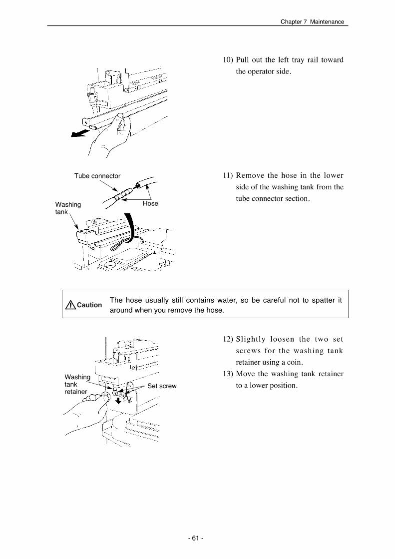
Chapter 7 Maintenance
- 61 -
10) Pull out the left tray rail toward
the operator side.
11) Remove the hose in the lower
side of the washing tank from the
tube connector section.
The hose usually still contains water, so be careful not to spatter itaround when you remove the hose.
12) Slightly loosen the two set
screws for the washing tank
retainer using a coin.
13) Move the washing tank retainer
to a lower position.
Tube connector
HoseWashingtank
Caution
Washingtankretainer
Set screw

SDP-Eco1630 III USERS MANUAL
- 62 -
Washing tank
Washing tank
Washingtankretainer
Set screw
Washing tank
Attachment section
Guide plate
14) Pull out the washing tank 30 to
40 mm toward the operator side
and remove it (toward the right).
15) Clean the washing tank with
water.
16) Insert the operator side of the
washing tank into the rectangular
slot in the processor. (See
illustration on the left.)
Slide the washing tank in
horizontally.
17) Set the back of the washing tank
on the guide plate and insert the
washing tank pressing it against
the left side of the guide.
18) Secure the operator side of the
tank with the washing tank
retainer.
Note
Washingtank

Chapter 7 Maintenance
- 63 -
Before securing the washing tank, lift the near end of the tank andits retainer as high up as possible Securely tighten the set screws using a coin.
19) Plug the removed hose back into
the tube connector.
20) Insert the back of the left tray rail
into the slit in the guide plate.
21) Secure the left tray rail with set
screws.
7.7 Replacing the diffusion sheet (SLM-EAC, SLM-EST)
1) Remove the processing chemical
supply guides from the processor
rack.
2) Loosen the two set screws for
each processing chemical supply
guide to remove the diffusion
sheet.
Slit
Left tray rail
Caution
Processor rack
Processingchemical supplyguide (SLM-EST)
Processingchemical supplyguide (SLM-EAC)

SDP-Eco1630 III USERS MANUAL
- 64 -
Tip of thebrush
3) Put the accompanying diffusion
sheet between the processing
chemical supply guide and
retaining bracket, then re-secure
the guides with set screws again.
Re-attach the brush bar in its
original position.
If the diffusion sheet (ELM-
EAC) is curved, mount it as
shown in figure on the left.
When a processingchemical supply guide(SLM-EAC) is attached,make sure the tip of thebrush bar touches theroller.
Caution
Note
Set screw
Set screw
Set screw
Set screwRetainingbracket
Diffusionsheet
Brush bar
Processingchemical diffusionguide (SLM-EAC)
Diffusionsheet
Retainingbracket
Processingchemical supplyguide (SLM-EST)
Diffusionsheet
Retainingbracket
Set screw
Set screw
Diffusionsheet

Chapter 7 Maintenance
- 65 -
7.8 List of expendable parts
After 25000 prepress processes, a "Pump Check" message appears on the
display panel when the power switch is turned ON.
This indicates that it is time to replace the pump, so please contact the
serviceman and request a pump replacement.
Always replace the pump units for EAC and EST at the same time.
Clear this panel display by pressing the RESET key and continue the initial
inspection.
Average lifetime varies depending on the usage condition (input voltage,
ambient environment, temperature, humidity, and daily maintenance).
When expendable parts noted in the list must be replaced, customers will be
charged for labor and parts costs even if the equipment is still within its
warrantee period.
7.9 How to order partsThe SDP-Eco 1630 III has many parts, some of which users can replace on
their own and some which require service personnel to replace. If you wish
to order any parts, please do the following:
(1) Indicate whether you just need the parts, or whether you need to have
them replaced by service personnel.
(2) Information from your warranty or machine name plate
i) Model: SDP-Eco 1630 III
ii) Serial number
(3) Names and numbers of necessary parts, quantities, date required
Please be aware that new models may be developed and specifications may change without notice, so parts may differ from those listed in this operation manual.Mitsubishi Paper Mills Ltd. takes no responsibility for improvementsusers may undertake on their own or in collaboration with another company.
Caution
Note
Parts name Parts code Unit When to replace
NT cutter blade 200400107 1 set (contains 10 blades)After cutting
two plate rolls.
Pump unit (EAC) 1 setAfter completing 25000
prepress processes.
Pump unit (EST)
U1105011
U1105012 After completing 25000 prepress processes.1 set

SDP-Eco1630 III USERS MANUAL
- 66 -
Pro
cedu
re
Item
Per
iod
Day
Mon
th
Ye
arS
DP
-Eco
163
0 III
Mai
nten
ance
and
Insp
ectio
n C
hart
Sup
ervi
sor
Dat
e
Blo
w th
e du
st a
nd d
irt o
ff th
e le
ns w
ith a
bl
ower
. (B
e ca
refu
l not
to s
crat
ch th
e le
ns.)
Rep
lace
the
blad
e fo
llow
ing
the
note
d �
repl
acem
ent p
roce
dure
.
Rem
ove
the
filte
r an
d cl
ean
it.E
very
thre
e �
mon
ths.
��
Dis
card
the
punc
h du
st. (
An
aler
t m
essa
ge a
ppea
rs a
fter
ever
y 10
00
punc
hes.
Tho
roug
hly
read
the
inst
ruct
ion
man
ual.
Eve
ry th
ree
�m
onth
s.�
�
Tho
roug
hly
read
the
inst
ruct
ion
man
ual.
Tho
roug
hly
read
the
inst
ruct
ion
man
ual.
Tho
roug
hly
read
the
inst
ruct
ion
man
ual.
Tho
roug
hly
read
the
inst
ruct
ion
man
ual.
Tho
roug
hly
read
the
inst
ruct
ion
man
ual.
1 2
3 4
5 6
7 8
9 10
11
12 1
3 14
15
16 1
7 18
19
20 2
1 22
23
24 2
5 26
27
28 2
9 30
31
NT
cut
ter
blad
e
Cyl
indr
ical
lens
As
nece
ssar
y
Filt
er c
lean
ing
Opt
iona
l pun
ch �
unit
Pro
cess
or s
ectio
n�cl
eani
ng
1. P
leas
e re
ad th
e in
stru
ctio
n m
anua
l car
eful
ly. 2
. Mar
k th
e da
te w
hen
the
insp
ectio
n is
per
form
ed. 3
. Cop
y th
is s
heet
and
use
this
sam
e fo
rm e
very
mon
th.
As
nece
ssar
y
Was
hing
tank
�cl
eani
ng
Pro
cess
ing
chem
ical
�ta
nk c
lean
ing
and
�ch
emic
al re
plac
emen
t
Pro
cess
ing
chem
ical
�su
pply
pip
e cl
eani
ng
Upp
er a
nd lo
wer
exi
t �ro
ller a
nd ri
nse
wat
er �
nip
rolle
r cle
anin
g
Rin
se w
ater
Eve
ry o
ne �
mon
th
Eve
ry th
ree
�m
onth
s or
afte
r �pr
oces
sing
�10
00m
2 of
pla
tes
Eve
ry th
ree
�m
onth
s
Eve
ry m
onth
or �
afte
r pro
cess
ing
�10
00 p
late
s
Eve
ry d
ay

Chapter 8 Message
Chapter 8 Message
8.1 MessageThe SDP-Eco 1630 III displays three kinds of messages: status messages,
warning messages and error messages.
[Status message]
Status messages indicate the machine's current operation status.
[Warning message]
Warning messages indicate a problem which has no effect currently but may
have adverse effects in the near future. These messages are displayed when
the power is turned ON.
Pressing the key allows you to continue processing.
[Error message]
Error messages indicate a problem or error which is now occurring during
operation. If an error message is displayed, a buzzer sounds and the machine
will not operate. Pressing the key while an error message is displayed
stops the buzzer sound.
The following pages contain a listing of common error codes, their meanings,
and corrective measures.
8.2 Displaying and clearing errorsWhen a problem or error occurs during operation, an error message is
displayed on the display panel and all moving parts, such as the motor, stop.
The machine will not operate while an error message is displayed.
[Error clearance]
Message Contents
ME1 First, stop the buzzer sound by pressing the key
and open the front door. After all required processes are
completed, close the front door and press the key.
This clears the error message.
*Do not turn OFF the main power when JAM1, JAM2,
JAM3 errors occur.
ME3 Turn the nip roller clearance handle until it is vertical
(locked) and then press the key to reset the error.
Others Eliminate the error with the key.
- 67 -
ME2
JAM1
JAM2
JAM3

8.3 Status display
Status displays indicate the machine's current operation status.
Message Operation status
Initializing Machine is being initialized.
Start OK Remote operation is ready.
Cleaning Processor is being cleaned.
Heating Processor is being heated.
Exposing Machine is exposing an image.
Recovery Machine is in recovery.
Discharging Plate is being discharged.
8.4 Warning display
Message Warning contents
Pump Check This indicates that it is time to replace the pump, so
please contact the dealer where you purchased this
machine and request a pump replacement.
Press the key to clear this display and continue
processing.
Punch Dust Check This indicates that the punch box is full of dust.
Open the plate setting cover and take out the punch box
to dispose of the dust.
Pressing the key resets the punch counter to "0".
Rinse Tank Check Check the remaining amount of rinse water in the rinse
water replenishing bottle. Push the key to delete the
message. Be sure to reset the software counter in the
machine. Open the front door, and then close it to reset
the counter. For detailed information, refer to section "6.7
Rinse".
SDP-Eco1630 III USERS MANUAL
- 68 -

8.5 List of error messages
The following is a list of error messages, and steps that can be taken.
Message Error contents
Serial error An internal communication error occurred. Re-boot the
machine.
If this error occurs frequently, please contact the dealer
where you purchased this machine.
JAM1 The plate is jammed. Remove the plate following the
jam removal procedure.
JAM2 The plate is jammed. Remove the plate following the
jam removal procedure.
JAM3 The plate is jammed. Remove the plate following the
jam removal procedure.
I/F error1 A SCSI communication error occurred. Re-boot the
machine. If this error occurs frequently, please contact
the dealer where you purchased this machine.
ME1 The cutter does not return to its initial position. Turn ON
the power switch again.
ME2 The cutter is not located at its initial position. Turn ON
the power switch again.
ME3 Nip free The nip roller is open. Close the nip roller clearance
handle.
ME4 An internal communication error occurred in the
machine. If this error occurs frequently, please contact
the dealer where you purchased this machine.
ME5 An internal communication error occurred. Re-boot the
machine.
If this error occurs frequently, please contact the dealer
where you purchased this machine.
ME6 The laser does not light. It may be caused by low laser,
but if it occurs even after you boost the laser, please
contact the dealer where you purchased this machine.
ME7 A problem occurred in the polygon mirror. Please
contact the dealer where you purchased this machine.
ME8 A problem occurred in the processor heater. Please
contact the dealer where you purchased this machine.
Chapter 8 Message
- 69 -
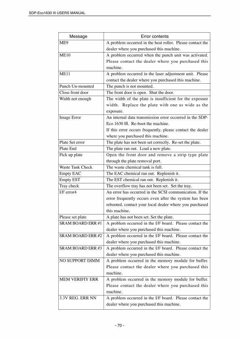
Message Error contentsME9 A problem occurred in the heat roller. Please contact the
dealer where you purchased this machine.
ME10 A problem occurred when the punch unit was activated.
Please contact the dealer where you purchased this
machine.
ME11 A problem occurred in the laser adjustment unit. Please
contact the dealer where you purchased this machine.
Punch Un-mounted The punch is not mounted.
Close front door The front door is open. Shut the door.
Width not enough The width of the plate is insufficient for the exposure
width. Replace the plate with one as wide as the
exposure.
Image Error An internal data transmission error occurred in the SDP-
Eco 1630 III. Re-boot the machine.
If this error occurs frequently, please contact the dealer
where you purchased this machine.
Plate Set error The plate has not been set correctly. Re-set the plate.
Plate End The plate ran out. Load a new plate.
Pick up plate Open the front door and remove a strip type plate
through the plate removal port.
Waste Tank Check The waste chemical tank is full.
Empty EAC The EAC chemical ran out. Replenish it.
Empty EST The EST chemical ran out. Replenish it.
Tray check The overflow tray has not been set. Set the tray.
I/F error4 An error has occurred in the SCSI communication. If the
error frequently occurs even after the system has been
rebooted, contact your local dealer where you purchased
this machine.
Please set plate A plate has not been set. Set the plate.
SRAM BOARD ERR #1 A problem occurred in the I/F board. Please contact the
dealer where you purchased this machine.
SRAM BOARD ERR #2 A problem occurred in the I/F board. Please contact the
dealer where you purchased this machine.
SRAM BOARD ERR #3 A problem occurred in the I/F board. Please contact the
dealer where you purchased this machine.
NO SUPPORT DIMM A problem occurred in the memory module for buffer.
Please contact the dealer where you purchased this
machine.
MEM VERIFIY ERR A problem occurred in the memory module for buffer.
Please contact the dealer where you purchased this
machine.
3.3V REG. ERR NN A problem occurred in the I/F board. Please contact the
dealer where you purchased this machine.
SDP-Eco1630 III USERS MANUAL
- 70 -
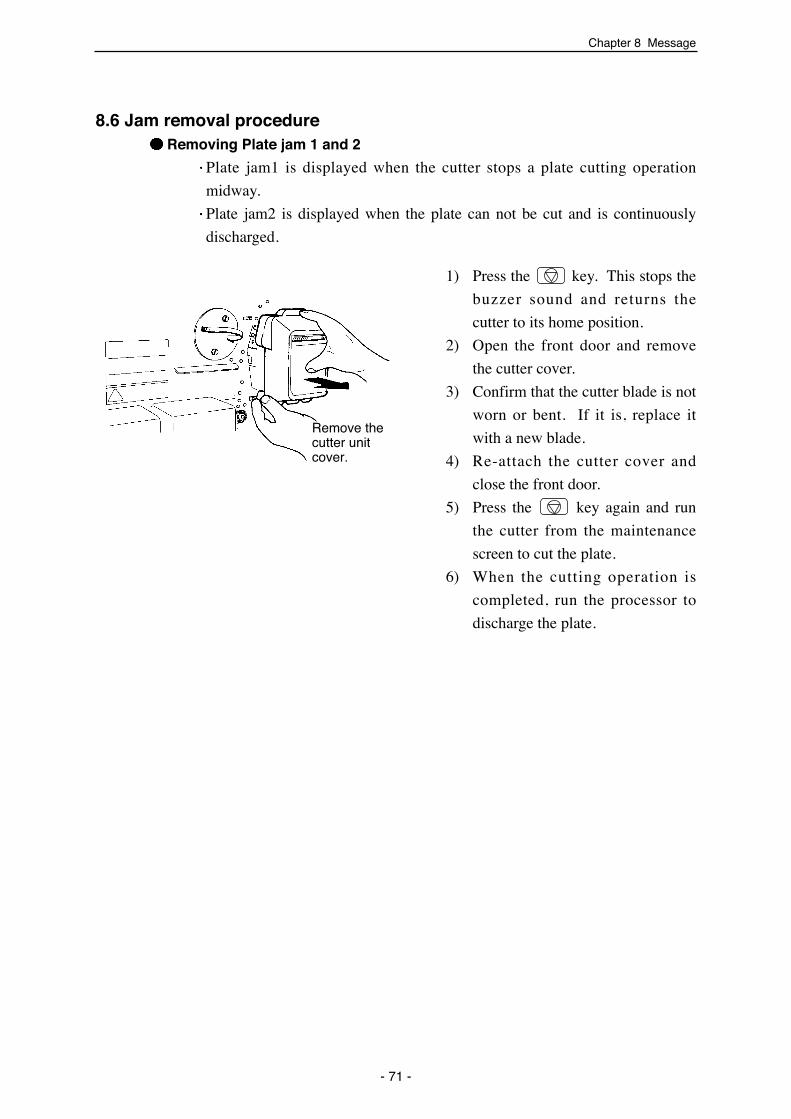
Chapter 8 Message
8.6 Jam removal procedureRemoving Plate jam 1 and 2
Plate jam1 is displayed when the cutter stops a plate cutting operation
midway.
Plate jam2 is displayed when the plate can not be cut and is continuously
discharged.
1) Press the key. This stops the
buzzer sound and returns the
cutter to its home position.
2) Open the front door and remove
the cutter cover.
3) Confirm that the cutter blade is not
worn or bent. If it is, replace it
with a new blade.
4) Re-attach the cutter cover and
close the front door.
5) Press the key again and run
the cutter from the maintenance
screen to cut the plate.
6) When the cutting operation is
completed, run the processor to
discharge the plate.
- 71 -
Remove thecutter unitcover.
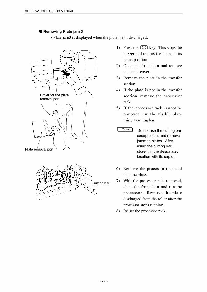
SDP-Eco1630 III USERS MANUAL
Removing Plate jam 3
Plate jam3 is displayed when the plate is not discharged.
1) Press the key. This stops the
buzzer and returns the cutter to its
home position.
2) Open the front door and remove
the cutter cover.
3) Remove the plate in the transfer
section.
4) If the plate is not in the transfer
section, remove the processor
rack.
5) If the processor rack cannot be
removed, cut the visible plate
using a cutting bar.
Do not use the cutting barexcept to cut and removejammed plates. Afterusing the cutting bar,store it in the designatedlocation with its cap on.
6) Remove the processor rack and
then the plate.
7) With the processor rack removed,
close the front door and run the
processor. Remove the plate
discharged from the roller after the
processor stops running.
8) Re-set the processor rack.
Caution
- 72 -
Cutting bar
Cover for the plateremoval port
Plate removal port

Chapter 9 Specifications
Chapter 9 Specifications
9.1 Basic specificationsRecording system ... Flatbed scanning systemLight source ... 635 nm laser diodeResolution ... 1200 dpi, 1500 dpi, 1800 dpi, 2400 dpiExposure speed ... 1236 mm/min (1200 dpi)
791 mm/min (1500 dpi)552 mm/min (1800 dpi)309 mm/min (2400 dpi)
Plates ... SDP-FR100 (Winding length: 75 meters)SDP-FRm175 (Winding length: 61 meters)SDP-RR175 (Winding length: 75 meters)
Plate width [cm (inches)] ... 22.9 (9), 25.4 (10), 27.9 (11), 30.5 (12),31.0 (12 1/5),32.4 (12 3/4), 33.5 (13 3/16),34.0 (13 3/8),37.0 (14 9/16), 40.0 (15 3/4),40.4 (15 7/8),41.4 (16 3/10)
Effective exposure width ... 404 mmMaximum exposure width ... 424 mmPlate cut length ... 220 to 580 mmCutter ... Slide cutterPlate joint detector ... Panel display, automatic over cutDehumidifier ... Panel heaterActivation method ... Coating (Ecology adapted model)Tank capacity ... SLM-EAC 0.55 liters, SLM-EST 0.6 litersProcessing chemicals ... SLM-EAC, SLM-EST (2 liters per bottle)Rinse water tank ... 0.26 litersRinse water ... Rinse water replenisher bottle 1.0 litersProcessor speed ... 15 mm/sec.Original speed ... 114 sec. (1200 dpi 450 mm long)Cycle time ... 46 sec. (1200 dpi 450 mm long)Solution temperature control ... 140W (AC 115V) panel heater 30 to 34 ˚CPlate preheater ... 140W (AC 115V) heat rollerDryer ... 600W (AC 115V) fin heater
Thermo controller switch system (H or L)Interface ... FAST WIDE SCSI (16 bit)Power supply capacitance ... Single phase 100 to 120V, 10A, 1.2 kW, 50/60 Hz
Single phase 200V 6A/ 220V 5.5A/ 230V 5.5A240V 5A/ 1.2 kW 50/60 Hz
Machine size (mm) ... W 1000 x D 795 x H 1070Weigh ... 100 to 120V type: 185 kg
200/220/230/240V type: 207 kgInstallation environment ... Temperature 23 5˚C, Humidity 50 to 70%Noise ... 60 dB (A) or lowerOption ... Memory module for extension
Differential unit (Cable 20 meters)DS punch unit (Alternately positionable)BELL punch unit
- 73 -

SDP-Eco1630 III USERS MANUAL
9.2 Overview diagram
- 74 -
(Unit: mm)
1770
465 305
900 50
795
545 136
1325
1072
561000

SILVER DIGIPLATER
(Feb. 2005)
SDP-Eco1630 III
Printed in Japan
USERS MANUAL